Embed Size (px)
Citation preview
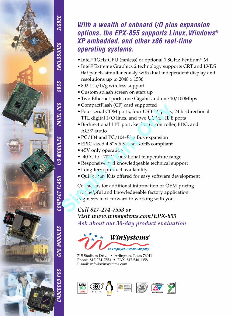
715 Stadium Drive • Arlington, Texas 76011Phone 817-274-7553 • FAX 817-548-1358 E-mail: [email protected]
Call 817-274-7553 or Visit www.winsystems.com/EPX-855Ask about our 30-day product evaluation
• Intel® 1GHz CPU (fanless) or optional 1.8GHz Pentium® M • Intel® Extreme Graphics 2 technology supports CRT and LVDS
flat panels simultaneously with dual independent display andresolutions up to 2048 x 1536
• 802.11a/b/g wireless support • Custom splash screen on start up• Two Ethernet ports; one Gigabit and one 10/100Mbps• CompactFlash (CF) card supported• Four serial COM ports, four USB 2.0 ports, 24 bi-directional
TTL digital I/O lines, and two UDMA IDE ports• Bi-directional LPT port, keyboard controller, FDC, and
AC97 audio• PC/104 and PC/104-Plus Bus expansion • EPIC sized 4.5" x 6.5" and RoHS compliant• +5V only operation • -40°C to +70°C operational temperature range• Responsive and knowledgeable technical support• Long-term product availability• Quick Start Kits offered for easy software development
Contact us for additional information or OEM pricing. Our helpful and knowledgeable factory application engineers look forward to working with you.
EMBE
DD
ED P
CS
G
PS M
OD
ULE
S
C
OM
PACT
FLA
SH
I/O
MO
DU
LES
PA
NEL
PCS
S
BCS
EN
CLO
SUR
ES
ZI
GBE
E
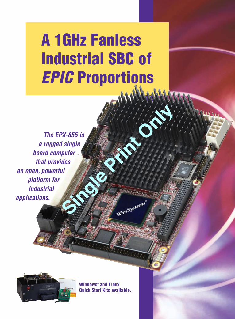
The EPX-855 is a rugged single
board computerthat provides
an open, powerfulplatform for industrial
applications.
With a wealth of onboard I/O plus expansionoptions, the EPX-855 supports Linux,Windows®
XP embedded, and other x86 real-time operating systems.
A 1GHz FanlessIndustrial SBC of EPIC Proportions
Windows® and LinuxQuick Start Kits available.
WinSystems EPX-855 ECDMar Ad 1/23/09 5:29 PM Page 1
Single Prin
t Only
Single Prin
t Only
715 Stadium Drive • Arlington, Texas 76011Phone 817-274-7553 • FAX 817-548-1358 E-mail: [email protected]
Call 817-274-7553 or Visit www.winsystems.com/EPX-855Ask about our 30-day product evaluation
• Intel® 1GHz CPU (fanless) or optional 1.8GHz Pentium® M • Intel® Extreme Graphics 2 technology supports CRT and LVDS
flat panels simultaneously with dual independent display andresolutions up to 2048 x 1536
• 802.11a/b/g wireless support • Custom splash screen on start up• Two Ethernet ports; one Gigabit and one 10/100Mbps• CompactFlash (CF) card supported• Four serial COM ports, four USB 2.0 ports, 24 bi-directional
TTL digital I/O lines, and two UDMA IDE ports• Bi-directional LPT port, keyboard controller, FDC, and
AC97 audio• PC/104 and PC/104-Plus Bus expansion • EPIC sized 4.5" x 6.5" and RoHS compliant• +5V only operation • -40°C to +70°C operational temperature range• Responsive and knowledgeable technical support• Long-term product availability• Quick Start Kits offered for easy software development
Contact us for additional information or OEM pricing. Our helpful and knowledgeable factory application engineers look forward to working with you.
EMBE
DD
ED P
CS
G
PS M
OD
ULE
S
C
OM
PACT
FLA
SH
I/O
MO
DU
LES
PA
NEL
PCS
S
BCS
EN
CLO
SUR
ES
ZI
GBE
E
The EPX-855 is a rugged single
board computerthat provides
an open, powerfulplatform for industrial
applications.
With a wealth of onboard I/O plus expansionoptions, the EPX-855 supports Linux,Windows®
XP embedded, and other x86 real-time operating systems.
A 1GHz FanlessIndustrial SBC of EPIC Proportions
Windows® and LinuxQuick Start Kits available.
WinSystems EPX-855 ECDMar Ad 1/23/09 5:29 PM Page 1
Single Prin
t Only
Single Prin
t Only
Columns
Resource Guide
4 \ March 2009 Embedded Computing Design Resource Guide
enviroink.indd 1 10/1/08 10:44:38 AM
Special Feature 16 What’s in your platform?
By Jerry Gipper
Chip and board debugging22 Protocol analyzers simplify USB
debuggingBy Etai Bruhis, Total Phase
Core IP licensing26 Software Bill of Materials improves
Intellectual Property managementBy Mahshad Koohgoli, PhD, and Sorin Cohn-Sfetcu, PhD, Protecode
Programmable logic 28 The high price of low-cost
FPGA development boardsBy Rob Evans, Altium Limited
Software32 Trends are good for press, not necessarily
for socketsBy Jean J. Labrosse, Micrium
8 Editor’s ForewordIs now the time to invest in tools?
By Jerry Gipper
10 Technology PassportLook Ma, no driver
By Hermann Strass
12 Consortia ConnectionSmart standards for wireless technologies
14 Ingenuity @ workSimplified HMI development
Design aids 34Interfaces 35Microcontrollers and processors 36Power management 39Programmable logic 40Software 47
Features
Departments
52 Editor’s Choice ProductsBy Jerry Gipper
2009 OpenSystems Media ® © 2009 Embedded Computing DesignAll registered brands and trademarks in Embedded Computing Design are property of their respective owners.
Volume 7 • Number 2 www.embedded-computing.com
Cover/Web Resources/EventsOn the coverPlatform-Oriented Architectures (POAs) can be packaged in layers, making systems integration easier. Check out the Special Feature starting on page 16 for more information on how POAs can help resolve design challenges.
E-casts Register at: www.embedded-computing.com/ecast
What makes a Real-Time OS indispensable?March 12, 11 a.m. EDT
Embedded multicore system development fundamentalsMarch 12, 2 p.m. EDT
E-letter www.embedded-computing.com/eletter
PCIe Gen 2: Not just more bandwidthBy Touseef Bhatti, PLX Technology
Web ResourcesSubscribe to the magazine or E-letter at:www.opensystemsmedia.com/subscriptions
Read industry news at:www.embedded-computing.com/news
Submit news releases, new products, white papers, and videos at:submit.opensystemsmedia.com
EventsMulticore ExpoMarch 16-19 • Santa Clara, CA www.multicore-expo.com
Embedded Systems Conference Silicon ValleyMarch 30-April 3 • San Jose, CAhttp://esc-sv09.techinsightsevents.com
Single Prin
t Only
Single Prin
t Only
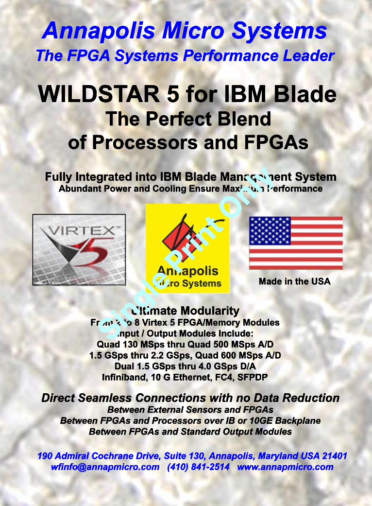
Annapolis Micro Systems
Made in the USA
Ultimate ModularityFrom 2 to 8 Virtex 5 FPGA/Memory Modules
Input / Output Modules Include:Quad 130 MSps thru Quad 500 MSps A/D
1.5 GSps thru 2.2 GSps, Quad 600 MSps A/DDual 1.5 GSps thru 4.0 GSps D/A
Infiniband, 10 G Ethernet, FC4, SFPDPInfiniband, 10 G Ethernet, FC4, SFPDP
Fully Integrated into IBM Blade Management SystemAbundant Power and Cooling Ensure Maximum Performance
Direct Seamless Connections with no Data ReductionBetween External Sensors and FPGAs
Between FPGAs and Processors over IB or 10GE BackplaneBetween FPGAs and Standard Output Modules
WILDSTAR 5 for IBM BladeThe Perfect Blend
of Processors and FPGAs
The FPGA Systems Performance Leader
190 Admiral Cochrane Drive, Suite 130, Annapolis, Maryland USA [email protected] (410) 841-2514 www.annapmicro.com
Single Prin
t Only
Single Prin
t Only
Dennis Doyle, Senior Account Manager [email protected]
Tom Varcie, Senior Account Manager [email protected]
Doug Cordier, Account Manager [email protected]
Andrea Stabile, Advertising/Marketing Coordinator [email protected]
Christine Long, Digital Content Manager [email protected]
International Sales Dan Aronovic, Account Manager – Israel [email protected]
Sam Fan, Account Manager – Asia [email protected]
Regional Sales Managers Ernest Godsey, Central and Mountain States [email protected]
Barbara Quinlan, Midwest/Southwest [email protected]
Denis Seger, Southern California [email protected]
Sydele Starr, Northern California [email protected]
Ron Taylor, East Coast/Mid Atlantic [email protected]
Nan Lamade 800-259-0470 [email protected]
Jerry Gipper, Editorial Director [email protected]
Don Dingee, Contributing Editor
Jennifer Hesse, Senior Associate Editor [email protected]
Hermann Strass, European Representative [email protected]
David Diomede, Art Director
Steph Sweet, Creative Director
Konrad Witte, Senior Web Developer
Joann Toth, Senior Designer
Monique DeVoe, Copy Editor
Phyllis Thompson, Circulation/Office Manager [email protected]
Embedded and Test & Analysis Group
Sales Group
ISSN: Print 1542-6408, Online 1542-6459
Embedded Computing Design is published 8 times a year by OpenSystems Media LLC, 16626 E. Avenue of the Fountains, Ste. 203, Fountain Hills, AZ 85268.
Subscrip tions are free to persons interested in the design or promotion of embedded computing systems. For others inside the US and Canada, sub scriptions are $56/year. For 1st class delivery outside the US and Canada, subscriptions are $80/year (advance payment in US funds required).
Canada: Publication agreement number 40048627Return address: WDS, Station A, PO Box 54, Windsor, ON N9A 615
POSTMASTER: Send address changes to Embedded Computing Design, 16626 E. Avenue of the Fountains, Ste. 203, Fountain Hills, AZ 85268
Reprints and PDFs
Editorial/Business Office16626 E. Avenue of the Fountains, Ste. 203 Fountain Hills, AZ 85268 Tel: 480-967-5581 n Fax: 480-837-6466 Website: www.opensystemsmedia.com
Publishers: John Black, Michael Hopper, Wayne Kristoff
Vice President Editorial: Rosemary Kristoff
Vice President Marketing & Sales: Patrick Hopper [email protected]
Business Manager: Karen Layman
E M B E D D E D S Y S T E M SINDUSTRIAL
EMBEDDED SYSTEMSMilitary form factorssmall
Single Prin
t Only
Single Prin
t Only
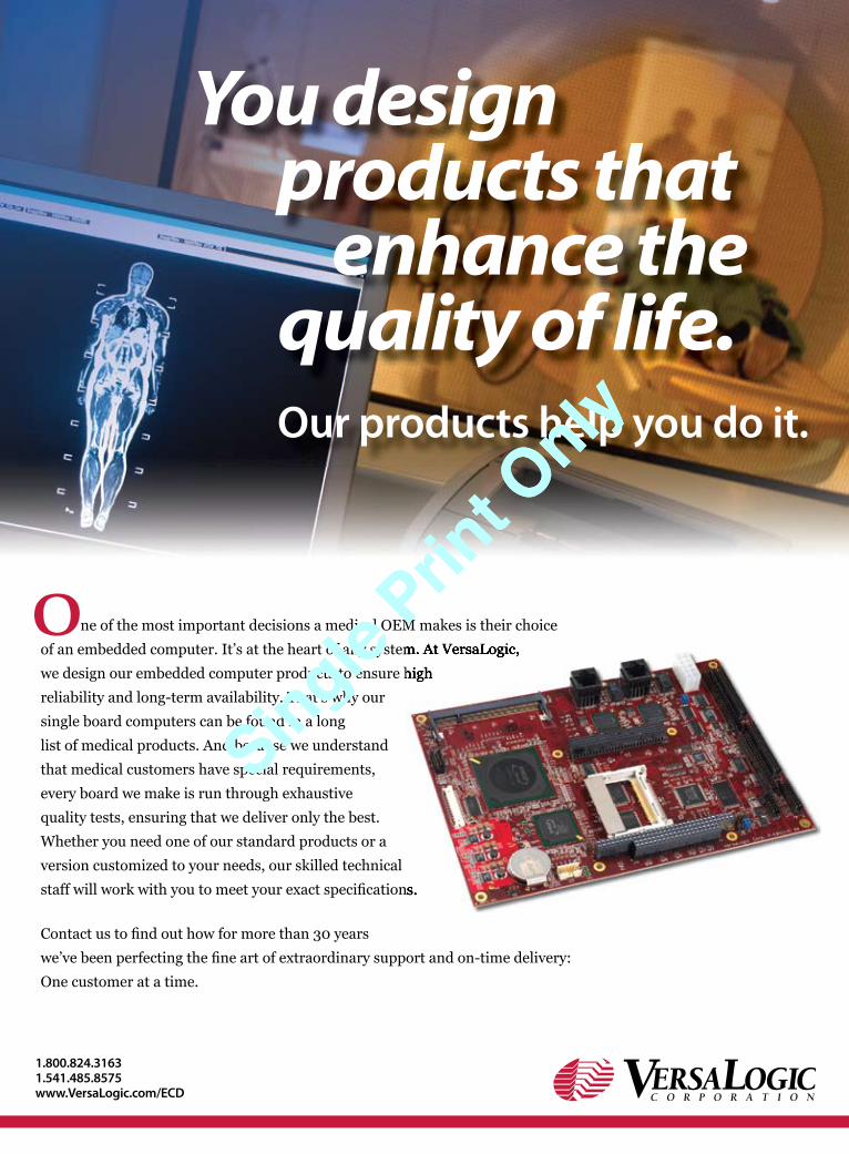
ne of the most important decisions a medical OEM makes is their choice
of an embedded computer. It’s at the heart of any system. At VersaLogic,
we design our embedded computer products to ensure high
reliability and long-term availability. That’s why our
single board computers can be found in a long
list of medical products. And because we understand
that medical customers have special requirements,
every board we make is run through exhaustive
quality tests, ensuring that we deliver only the best.
Whether you need one of our standard products or a
version customized to your needs, our skilled technical
staff will work with you to meet your exact specifi cations.
Contact us to fi nd out how for more than 30 years
we’ve been perfecting the fi ne art of extraordinary support and on-time delivery:
One customer at a time.
You design products that enhance the quality of life.
Our products help you do it.
1.800.824.31631.541.485.8575 www.VersaLogic.com/ECD
O of an embedded computer. It’s at the heart of any system. At VersaLogic,
we design our embedded computer products to ensure high
staff will work with you to meet your exact specifi cations.
of an embedded computer. It’s at the heart of any system. At VersaLogic,
we design our embedded computer products to ensure high
staff will work with you to meet your exact specifi cations.
Single Prin
t Only
Single Prin
t Only

8 \ March 2009 Embedded Computing Design Resource Guide
Editor’sForeword
Jerry Gipper
Editor’s Foreword
Determining when you should invest in development tools is often a hard decision to make, especially during an economic recession. Yet it is still a decision that needs to be made.
During boom times, the push to get more done is commonly addressed by throwing more human resources at a design task, with managers asking for more engineers to keep projects on schedule. Investments in development tools and new processes take a backseat. These investments meet resistance because design teams don’t have the luxury of taking time to investigate toolset options or to learn a new tool suite and processes. They are focused on getting the project out the door on time.
During economic declines, resources are stretched as companies make cutbacks in staff and spending. Getting sign-off on new development tools is not likely to get any attention while projects fall behind.
Several studies illustrate the ben-efits of using advanced development tools such as simulators, Model-Driven Development (MDD) tools, and other electronic design automa-tion tools. How much time and money can be saved varies, but most reports reach the conclusion that definite savings can be achieved. A December 2008 report titled “The Economics of Embedded Development, Testing, Deployment, and Support” by Embedded Market Forecasters (www.embeddedforecast.com) presents an example that shows how companies can attain project improve-ment approaching 30 percent. There is no question that good, solid development tools can reduce development cycle times, shorten time to market, and improve the quality of your product.
Selecting the right solutions is another story. Development tools come in all types, from simple and basic to very complex and robust. You must clearly understand each tool and how it will work in your design environment. The often inexpensive entry-level tools might not have the right sets of features. For instance, a low-end MDD tool might not provide validation or traceability
to your requirements, reduce programming errors or test time, or improve the quality of the final product as expected.
On the other hand, deluxe tools can be overkill, with features that are not necessary for your development environment or that are so complicated that they are difficult to learn or use.
Don’t let price be the sole driver. Sometimes the best tools are inexpensive; other times, “you get what you pay for” applies. You should employ an in-house specialist who tracks develop-ment tools, someone you can turn to when a decision needs to be made. A readily available expert who fully understands the pros and cons of a tool and can interpret its impact on your orga-
nization and projects is hard to come by. Relying on marketing hype and sales pressure can lead you astray.
My belief is that now is the right time to consider investments in upgrading your development tools. You will want to be in a position to recover from this down-turn quickly, riding the upslope that will likely occur in the coming months.
With the right investment, you could save 25-30 percent on your next project,
reduce time to market, meet schedule commitments, and produce better design results.
As you eventually start restaffing, look for engineers who are competent and skilled in using these new tools. Underemployed engineers should take advantage of this time to learn new tools, making them more marketable assets to the companies that will emerge out of this recession.
Feel free to share your comments through e-mail or visit our blog at www.embedded-computing.com to add your comments.
Jerry GipperEditorial [email protected]
Is now the time to invest in tools?
Don’t let price be the sole
driver. Sometimes the best
tools are inexpensive; other
times, “you get what you
pay for” applies.Single
Print O
nly
Single Prin
t Only
10 \ March 2009 Embedded Computing Design Resource Guide
Editor’s Foreword
Technology Passport
Hermann Strass Look Ma, no driver
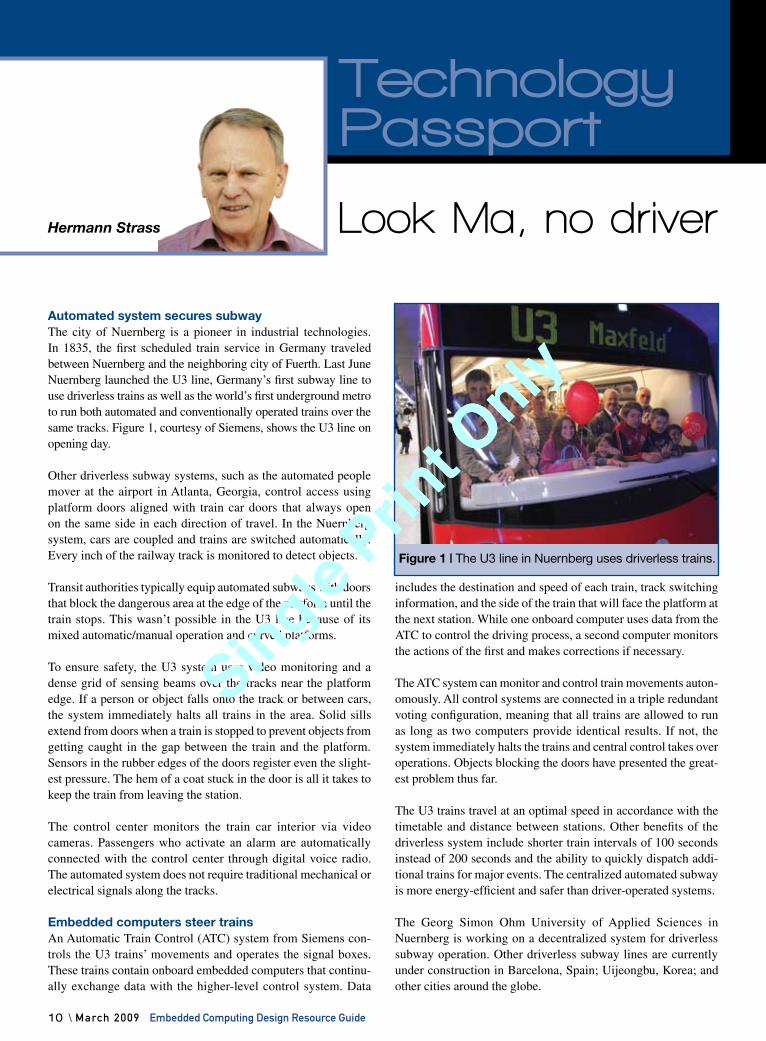
Automated system secures subwayThe city of Nuernberg is a pioneer in industrial technologies. In 1835, the first scheduled train service in Germany traveled between Nuernberg and the neighboring city of Fuerth. Last June Nuernberg launched the U3 line, Germany’s first subway line to use driverless trains as well as the world’s first underground metro to run both automated and conventionally operated trains over the same tracks. Figure 1, courtesy of Siemens, shows the U3 line on opening day.
Other driverless subway systems, such as the automated people mover at the airport in Atlanta, Georgia, control access using platform doors aligned with train car doors that always open on the same side in each direction of travel. In the Nuernberg system, cars are coupled and trains are switched automatically. Every inch of the railway track is monitored to detect objects.
Transit authorities typically equip automated subways with doors that block the dangerous area at the edge of the platform until the train stops. This wasn’t possible in the U3 line because of its mixed automatic/manual operation and curved platforms.
To ensure safety, the U3 system uses video monitoring and a dense grid of sensing beams over the tracks near the platform edge. If a person or object falls onto the track or between cars, the system immediately halts all trains in the area. Solid sills extend from doors when a train is stopped to prevent objects from getting caught in the gap between the train and the platform. Sensors in the rubber edges of the doors register even the slight-est pressure. The hem of a coat stuck in the door is all it takes to keep the train from leaving the station.
The control center monitors the train car interior via video cameras. Passengers who activate an alarm are automatically connected with the control center through digital voice radio. The automated system does not require traditional mechanical or electrical signals along the tracks.
Embedded computers steer trainsAn Automatic Train Control (ATC) system from Siemens con-trols the U3 trains’ movements and operates the signal boxes. These trains contain onboard embedded computers that continu-ally exchange data with the higher-level control system. Data
includes the destination and speed of each train, track switching information, and the side of the train that will face the platform at the next station. While one onboard computer uses data from the ATC to control the driving process, a second computer monitors the actions of the first and makes corrections if necessary.
The ATC system can monitor and control train movements auton-omously. All control systems are connected in a triple redundant voting configuration, meaning that all trains are allowed to run as long as two computers provide identical results. If not, the system immediately halts the trains and central control takes over operations. Objects blocking the doors have presented the great-est problem thus far.
The U3 trains travel at an optimal speed in accordance with the timetable and distance between stations. Other benefits of the driverless system include shorter train intervals of 100 seconds instead of 200 seconds and the ability to quickly dispatch addi-tional trains for major events. The centralized automated subway is more energy-efficient and safer than driver-operated systems.
The Georg Simon Ohm University of Applied Sciences in Nuernberg is working on a decentralized system for driverless subway operation. Other driverless subway lines are currently under construction in Barcelona, Spain; Uijeongbu, Korea; and other cities around the globe.
Figure 1 | The U3 line in Nuernberg uses driverless trains.
Technology Passport
Single Prin
t Only
Single Prin
t Only
Embedded Computing Design Resource Guide March 2009 / 11
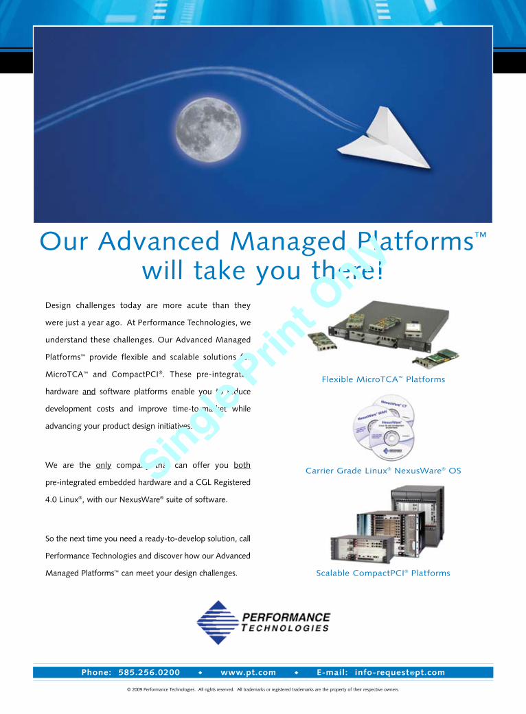
Design challenges today are more acute than they
were just a year ago. At Performance Technologies, we
understand these challenges. Our Advanced Managed
Platforms™ provide flexible and scalable solutions for
MicroTCA™ and CompactPCI®. These pre-integrated
hardware and software platforms enable you to reduce
development costs and improve time-to-market while
advancing your product design initiatives.
We are the only company that can offer you both
pre-integrated embedded hardware and a CGL Registered
4.0 Linux®, with our NexusWare® suite of software.
So the next time you need a ready-to-develop solution, call
Performance Technologies and discover how our Advanced
Managed Platforms™ can meet your design challenges.
Our Advanced Managed Platforms™
will take you there!
© 2009 Performance Technologies. All rights reserved. All trademarks or registered trademarks are the property of their respective owners.
Phone: 585.256.0200 www.pt.com E-mail: [email protected]
Flexible MicroTCA™ Platforms
Carrier Grade Linux® NexusWare® OS
Scalable CompactPCI® Platforms
Single Prin
t Only
Single Prin
t Only
12 \ March 2009 Embedded Computing Design Resource Guide
Smart standards for wireless technologies
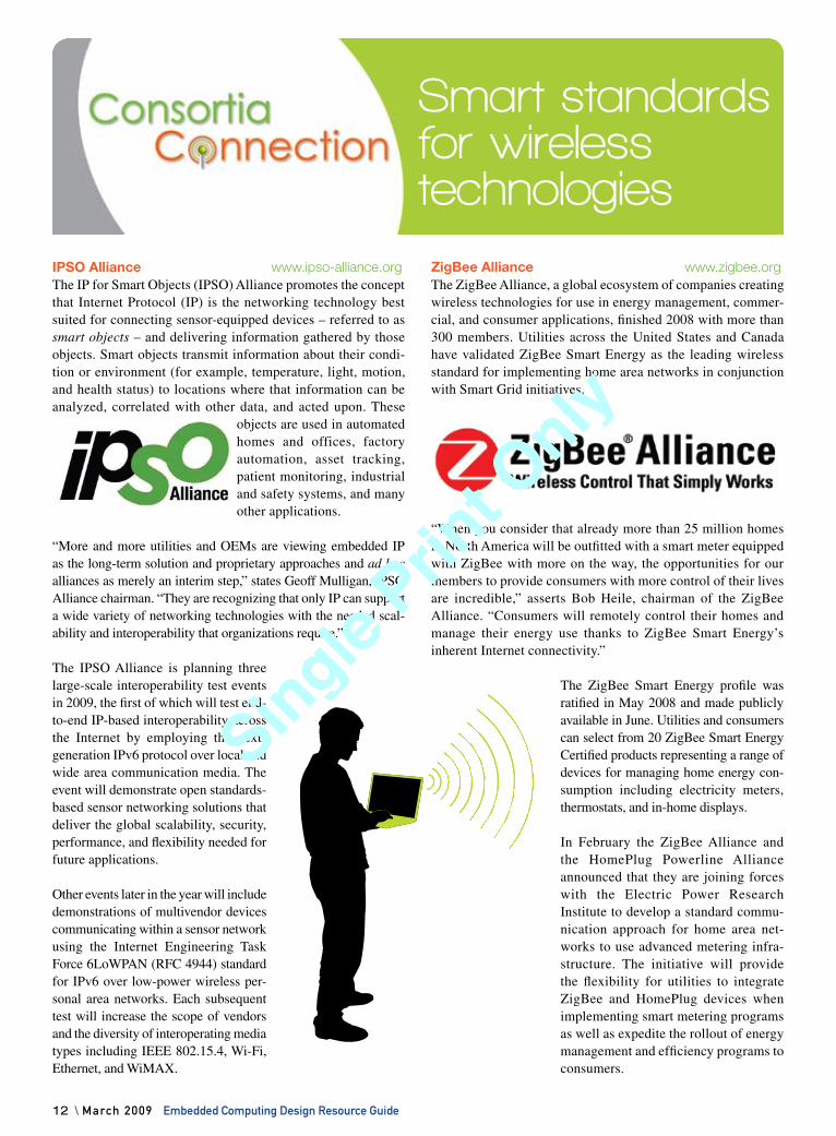
IPSO Alliance www.ipso-alliance.orgThe IP for Smart Objects (IPSO) Alliance promotes the concept that Internet Protocol (IP) is the networking technology best suited for connecting sensor-equipped devices – referred to as smart objects – and delivering information gathered by those objects. Smart objects transmit information about their condi-tion or environment (for example, temperature, light, motion, and health status) to locations where that information can be analyzed, correlated with other data, and acted upon. These
objects are used in automated homes and offices, factory automation, asset tracking, patient monitoring, industrial and safety systems, and many other applications.
“More and more utilities and OEMs are viewing embedded IP as the long-term solution and proprietary approaches and ad hoc alliances as merely an interim step,” states Geoff Mulligan, IPSO Alliance chairman. “They are recognizing that only IP can support a wide variety of networking technologies with the needed scal-ability and interoperability that organizations require.”
The IPSO Alliance is planning three large-scale interoperability test events in 2009, the first of which will test end-to-end IP-based interoperability across the Internet by employing the next-generation IPv6 protocol over local and wide area communication media. The event will demonstrate open standards-based sensor networking solutions that deliver the global scalability, security, performance, and flexibility needed for future applications.
Other events later in the year will include demonstrations of multivendor devices communicating within a sensor network using the Internet Engineering Task Force 6LoWPAN (RFC 4944) standard for IPv6 over low-power wireless per-sonal area networks. Each subsequent test will increase the scope of vendors and the diversity of interoperating media types including IEEE 802.15.4, Wi-Fi, Ethernet, and WiMAX.
ZigBee Alliance www.zigbee.orgThe ZigBee Alliance, a global ecosystem of companies creating wireless technologies for use in energy management, commer-cial, and consumer applications, finished 2008 with more than 300 members. Utilities across the United States and Canada have validated ZigBee Smart Energy as the leading wireless standard for implementing home area networks in conjunction with Smart Grid initiatives.
“When you consider that already more than 25 million homes in North America will be outfitted with a smart meter equipped with ZigBee with more on the way, the opportunities for our members to provide consumers with more control of their lives are incredible,” asserts Bob Heile, chairman of the ZigBee Alliance. “Consumers will remotely control their homes and manage their energy use thanks to ZigBee Smart Energy’s inherent Internet connectivity.”
The ZigBee Smart Energy profile was ratified in May 2008 and made publicly available in June. Utilities and consumers can select from 20 ZigBee Smart Energy Certified products representing a range of devices for managing home energy con-sumption including electricity meters, thermostats, and in-home displays.
In February the ZigBee Alliance and the HomePlug Powerline Alliance announced that they are joining forces with the Electric Power Research Institute to develop a standard commu-nication approach for home area net-works to use advanced metering infra-structure. The initiative will provide the flexibility for utilities to integrate ZigBee and HomePlug devices when implementing smart metering programs as well as expedite the rollout of energy management and efficiency programs to consumers.
Single Prin
t Only
Single Prin
t Only

For land-based or airborne applications, the military needs COTS embedded sub-systems that deliver the optimum combination of performance, reliability, cost and rapid time-to-market. And Aitech has delivered just that since 1983!
We’re still in front... Aitech got a big jump on everyone way back when...and we’ve kept well ahead of the pack in developingadvanced embedded sub-systems based on leading edge commercial technologies adapted to harsh environment applications.
We don't compete with you... A lot of board level companies claim to be systems integrators. We don't. We leave the systems integration to the companies that do it best: our customers...companies just like yours!
We have what it takes... Our VME and CompactPCI SBCs, PMCs, memory, I/O, graphics and chassis are in a class by themselves. And they’re backed by world class software and technical support, program and lifecycle management, testing and more.
We’ve been there... Aitech sub-systems are in widespread use in the world’s most demanding military/aerospace applications: from radar, missile and weapons control to mission-critical data voice sub-systems...from mission computers and display consoles to ECM, sight head stabilization and counter measure control...from power control and conditioning to advanced imaging systems. And that’s just for starters.
Don't take our word for it... Compare Aitech's offerings and expertise to any company in the COTS embedded marketplace. Land or air. Or for that matter, sea or space. Come to talk to us.
Aitech Defense Systems, Inc.19756 Prairie Street Chatsworth, CA 91311 email: [email protected] Toll Free: 888-Aitech8 - (888) 248-3248 Fax: (818) 718-9787www.rugged.com
AIT-F-1587 EmbCompDes 1/29/09 4:39 PM Page 1
Single Prin
t Only
Single Prin
t Only
Ingenuitywork
Ingenuity @ work
solutio
npro
blem
Converting creativity into codeThis decade has seen dramatic improvements in display technology, generating an explosion of uses for graph-ics displays in desktop, workstation, and embedded sys-tems. From in-car navigation systems, mobile phones, and portable MP3 players to airports and power plants, flat-panel displays are showing up everywhere. Conse-quently, the HMI has emerged as a critical product differ-entiator that provides a window into an array of powerful product features.
Although display technology has improved dramatically, HMI software development has lagged behind, produc-ing many abysmal user interfaces. This delay can be attrib-uted to today’s complex, programmer-centric HMI tools, which discourage the participation of the graphic artists, industrial designers, and application experts needed to develop effective user interfaces. Furthermore, because today’s devices come with custom processors and/or Operating Systems (OSs), building user interfaces requires special skills and knowledge.
To aid designers in this difficult task, Altia provides cohe-sive, easy-to-use HMI development tools that wrap high-level modeling and graphical tools around detailed
custom programming. The tools hide the processor from developers so they can focus on their applications. A code generator produces code for the chosen processor architecture, and everything from graphics to logic gets used and reused.
Altia helps bridge the gap between the widely dissimi-lar needs of the creative process and the programming process. The company’s tools assist artists by providing a WYSIWYG graphics and HMI editor that allows them to draw and import graphics from their favorite graphics design tools. The software likewise aids programmers by providing code generators, language translators, APIs, and OS-specific graphics libraries that convert the artist’s HMI design into deployable code that can be integrated with the programmer’s application code and run on a variety of OSs and hardware.
Simplified HMI development
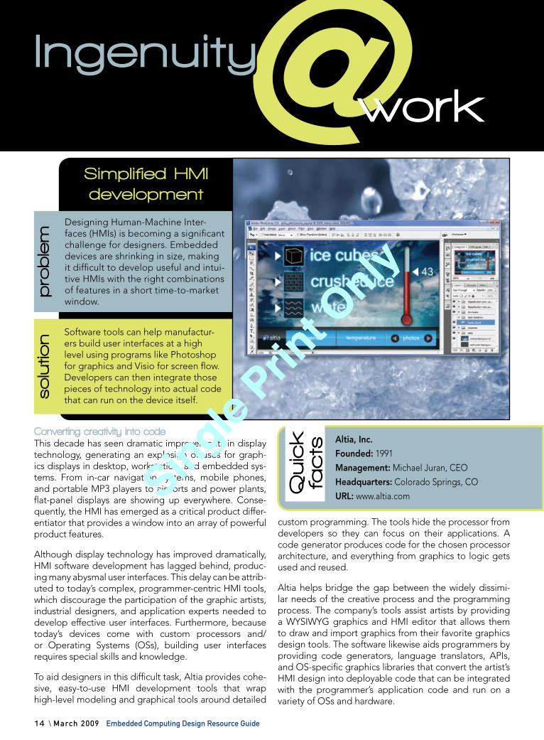
Software tools can help manufactur-ers build user interfaces at a high level using programs like Photoshop for graphics and Visio for screen flow. Developers can then integrate those pieces of technology into actual code that can run on the device itself.
Designing Human-Machine Inter-faces (HMIs) is becoming a significant challenge for designers. Embedded devices are shrinking in size, making it difficult to develop useful and intui-tive HMIs with the right combinations of features in a short time-to-market window.
Quick
facts
Altia, Inc.
Founded: 1991
Management: Michael Juran, CEO
Headquarters: Colorado Springs, CO
URL: www.altia.com
14 \ March 2009 Embedded Computing Design Resource Guide
Single Prin
t Only
Single Prin
t Only
“In today’s challenging business environment, developers are looking for ways to reduce cost through extensive software reuse and by leveraging turnkey platforms that combine best-of-breed hardware and software.” – Tony Massimini, chief of technology, Semico Research Corporation
POA definedThe definition of Platform-Oriented Architecture varies slightly from soft-ware to chips to boards to systems, but the concept remains the same. It is a bounded and integrated suite of compo-nents consisting of either or both soft-ware and hardware optimized to enable further integration into a final product
for a specific application. Advanced platforms combine hardware and asso-ciated software designed to serve as the basis for a number of different systems to be integrated. Many other devices – Systems-on-Chip (SoCs), Application-Specific Standard Products (ASSPs), SBCs, and systems in a variety of combi-nations – are now considered platforms.
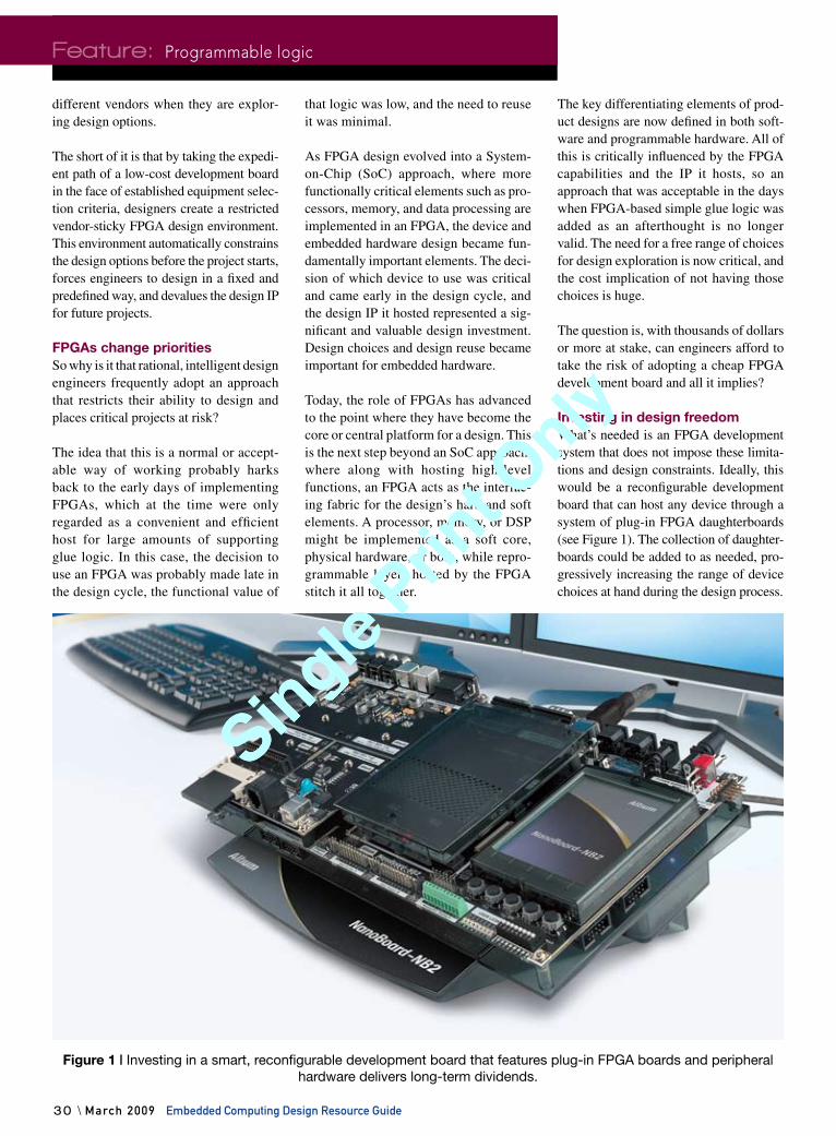
“The ultimate Platform-Oriented Architecture is an FPGA because you can do anything with it,” asserts Craig Rawlings, senior director of product man-agement at Certicom. “The idea of doing something universal is a pipe dream. But if we bind the problem, then it makes a lot of sense, and you can scope things in a way that streamlines a number of options, plus save on R&D and manufacturing.”
How platforms evolvedIn the early days of electronics, devices were usually custom-designed for a
specific objective. Hardware and software were designed from scratch and took for-ever to develop. As the market matured, suppliers started to anticipate the needs of developers, but they did so in haphaz-ard ways. They tried to maximize their market coverage and design products that served as many users as possible. General-purpose processors, computer boards, and Real-Time Operating Systems (RTOSs) emerged. Developers had to force-fit or tweak components to meet their specific application requirements.
From Rawlings’ perspective, the first POA was really a CPU because it was programmable; you could do anything with it. But microcontrollers were among the first to formally embrace the plat-form concept. Suppliers would package together the core processor with various configurations of memory and I/O to tar-get specific controller applications such as industrial control or medical devices.
Platform-Oriented Architecture
16 \ March 2009 Embedded Computing Design Resource Guide
Specia
l Featu
re
Designing embedded computer systems is always difficult. Innovative technologies with
increasing performance levels and smaller packaging present new obstacles every day.
Fortunately, suppliers are making design easier by promoting the concept of a Platform-
Oriented Architecture (POA), which provides a way to move up the supply chain and make the
design and integration efforts go more smoothly. Just as politicians use their platforms to kick-
start their programs, POAs provide a launching pad for embedded devices. So the question is,
what should you know about platforms before starting your next project?
What’s in your platform?By Jerry Gipper
Special FeatureHardware
16 \ March 2009 Embedded Computing Design
Single Prin
t Only
Single Prin
t Only
Rawlings speculates that system archi-tects stepped in and said, “Let’s not build an architecture that tries to be everything to everybody.” They proposed building a platform for a PDA or a mobile telephone – something more specific with binded features that are known requirements. Instead of building three chips or boards, designers could build one chip or board with selectable modes that can be turned off and on.
Eventually, suppliers started making alli-ances with others in the market to provide more complete solutions for embedded systems developers. Early attempts were loose alliances or ecosystems that cov-ered as many of the design bases as pos-sible. This made it easier for developers to get all the right pieces in place, but it still was a long road to product comple-tion. Designers had to contact and work with multiple sources, lacking the assur-ance that pieces were fully compatible or even available.
These alliances and ecosystems evolved over time. In many cases, the technologies were combined in packages that made the development path smoother and more efficient. Suppliers started talking about moving up the supply chain by offering more complete and integrated solutions. This strategy became even more effective as the electronic hardware and software suppliers began addressing specific appli-cation segments. Various hardware and
software components were integrated, and the platform concept stuck.
In time, the PC emerged as a dominant general-purpose platform. However, many embedded applications cannot use a PC platform because they have size, weight, and power restrictions that make it impractical to use a PC. This issue led to the development of platforms that address the specific needs of embedded applications. Functions specific to mar-ket applications, from mobile devices to communications infrastructure, were defined and developed.
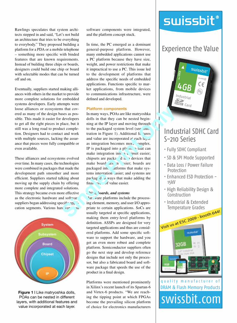
Platform componentsIn many ways, POAs are like matryoshka dolls in that they can be nested begin-ning at the IP layer and moving through to the packaged system level (see illus-tration in Figure 1). Additional features and value are incorporated at each layer as integration becomes more complex. IP is packaged into a platform that can make integration into a chipset easier; chipsets are packaged into devices that make board design easier; boards are packaged into platforms that make sys-tems integration easier; and systems are packaged in ways that make adding the final layers of value easier.
Chips, boards, and systemsHardware platforms include the process-ing element, memory, and user I/O appro-priate to certain applications. SoCs are usually targeted at specific applications, making them entry-level platforms by definition. ASSPs are designed for very targeted applications and thus are consid-ered platforms. Add some specific soft-ware to support the hardware, and you get an even more robust and complete platform. Semiconductor suppliers often go the next step and develop reference designs that include not only the proces-sor, but also a fabricated board and soft-ware package that speeds the use of the product in a final design.
Platforms were mentioned prominently in Xilinx’s recent launch of its Spartan-6 and Virtex-6 products. “We are reach-ing the tipping point at which FPGAs become the prevailing silicon platform of choice for electronics manufacturers
Industrial SDHC CardS-210 Series
q u a l i t y m a n u f a c t u r e r o f
DRAM & Flash Memory Products
• Fully SDHC Compliant
• SD & SPI Mode Supported
• Data Loss / Power Failure Protection• Enhanced ESD Protection - 15kV
• High Reliability Design & Construction
• Industrial & Extended Temperature Grades
Experience the Value
Visit us at ESC 2009 - booth 644!
Figure 1 | Like matryoshka dolls, POAs can be nested in different
layers, with additional features and value incorporated at each layer.
Single Prin
t Only
Single Prin
t Only

18 \ March 2009 Embedded Computing Design Resource Guide
Special Feature: Platform-Oriented Architecture
who need customization to differenti-ate their products but are faced with incredibly unattractive ASIC develop-ment costs,” remarks Moshe Gavrielov, Xilinx president and CEO. “But in order for customers to increase their adoption of FPGAs, it’s essential that we pro-vide a comprehensive design environ-ment that enables global design teams to address the ‘programmable imperative’ and deliver products faster under these challenging economic and business conditions.”
The Xilinx targeted design platform strat-egy encompasses the integration of five key elements:
New Xilinx Virtex-6 and Spartan-6 fFPGAs Design environments supporting fand integrating industry-proven methodologiesScalable boards and kits adopting the findustry-standard FPGA mezzanine connectorSocketable IP cores fRobust reference designs f
These elements were emphasized as important features in another recent prod-uct debut. The CEVA HD-Audio solution is supported by a Software Development Kit (SDK) that includes software develop-ment tools, development boards, software system drivers, and an RTOS to enable quick and easy system development and integration. The CEVA-HD-Audio is further complemented by extensive algo-rithms and applications from a third-party development community.
OSsOS platforms consist of an integrated suite of modules: the OS, firmware, and device drivers to run the target device’s peripherals, file system, libraries, com-munications protocols for connectivity, and user application. OS suppliers have expanded the integration layer of addi-tional software into their core OSs to incorporate much of the software that makes it easier to focus on the final appli-cation. They have continually improved the API, eliminating the need to worry about the routine middleware needed within an industry.
ToolsThe platform strategy also applies to development tools. Greg Sykes, direc-tor of architecture and modeling at IBM Rational, points out that tools benefit from being packaged into platforms spe-cific to certain market segments. Many companies such as cell phone and auto-motive manufacturers have their own methods for program management and development. Crafting platforms that conform to a familiar look and feel and providing tools that let designers quickly create modules needed by the application can save significant time in the lab.
The benefits of using a platformPlatforms resolve the problems involved in hardware and software component selection and ease the challenges of inte-grating and debugging the design, not to mention reduce the hassle of tracking down all the various components needed to develop a complete product. Today, suppliers tend to specialize in facets of the hardware or software needed for an embedded computer system. Because of this specialization, it can be very difficult
Single Prin
t Only
Single Prin
t Only
to chase down remaining components for the final design.
Other suppliers have eased this challenge by integrating the specialized compo-nents into a platform. The level of inte-gration can range from simply providing a reference, in which case it probably is not a true platform solution, to a fully integrated and tested configuration. The more integrated the platform, the higher the quality and reliability of the final product, if all goes to plan.
According to Wind River, development tools that are designed and tested with a platform strategy in mind can provide developers with visibility into the entire platform: application code, third-party libraries, and the OS. Developers can monitor variables, optimize performance, and find memory problems – all while the system is still running.
“Increasing competition coupled with chal-lenging economic conditions place further demands on organizations to implement innovative services that reduce costs and streamline operations,” states Greg Buzek, president of IHL Group. “By allowing plug-and-play connectivity with periph-erals, embedded OSs such as Windows Embedded POSReady 2009 provide the flexibility in system components and soft-ware that retailers need, allowing them to lower the cost of ownership and increase efficiencies at the front end.”
Targeted POAs help enable software and hardware designers alike to lever-age open standards, common design methodologies, development tools, and runtime platforms. This allows designers to spend less time developing applica-tion infrastructure and more time build-ing differentiating features into the end application.
IntegrationIntegration drives many of the other ben-efits of a platform, making it easier to add and replace components with some level of plug-and-play support. “We do the work of integrating all of this stuff together and making it work for a spe-cific architecture,” remarks Dan Cauchy, director of marketing at MontaVista.
“In some cases, we write a lot of this stuff ourselves – for example, the porting of the Mozilla browser to ARM.”
Cauchy mentions that getting integration to work at a high-quality level requires many staff-years of work. “Device man-ufacturers are telling us that this is really valuable because they get to start with an entire solution, and on top of that, it is fully supported by MontaVista,” he says.
Features and common interfacesTargeted POAs have the right set of fea-tures and interfaces for the target applica-tion. The choices have been well thought out and vetted through the target industry. Suppliers need to know their customers’ markets to make the right choices.
OS platforms provide a common API, minimizing or even eliminating the need to agonize over hardware. Programmers can write a more generic interface and not worry about the details of the device. On the hardware side, interfaces like Ethernet, USB, CAN, and other application-specific choices are supplied.
IP licensingAs companies have tried to get to market faster and others have attempted to spe-cialize, the use of third-party IP has sky-rocketed. This has created a huge hurdle in the form of licensing, which can be very complex and expensive to manage and monitor. Passing the burden of IP management on to the platform supplier can ease this pain.
InventoryA POA can impact inventory in many positive ways. A well-designed platform can be quickly configured to meet the needs of multiple customers in custom configurations. For instance, a chip-set supplier can build a single superset product in mass volumes while enabling specific features on demand as required by each customer. This allows the sup-plier to forecast an aggregate of parts instead of each individual configuration. This means less inventory, improved operational efficiency, and less price erosion because they are not trying to clear inventory.
Single Prin
t Only
Single Prin
t Only
20 \ March 2009 Embedded Computing Design Resource Guide
Special Feature: Platform-Oriented Architecture
DebuggingUsing a platform means that all of the modules do not need to be touched when troubleshooting. Platform components usually go through a rigorous debugging process before being deployed in many other related designs by other custom-ers. POAs often have a better debugging interface that can make the whole process easier because it is designed with the complete platform in mind.
TestingMany interfaces have industry test suites to ensure that the feature operates prop-erly. For example, USB has test suites and compliance testing developed by the USB Implementers Forum. If the plat-form provider has completed the testing, this eliminates or reduces the need to test to the same level at the next step. In highly complex systems with many inter-faces, this can save time and costs.
Standards and the ability to support changing standardsOrganizations throughout the embed-ded community develop and evangelize
standards necessary to the success of the industry. Platform suppliers are frequently key members of standards organizations, influencing the direction of the standard and ensuring its successful develop-ment. Many standards used in today’s embedded devices are new or changing. Platform developers can reduce the bur-den on the design engineer by keeping track of the latest developments, incor-porating them into the platform as they become available. You don’t have to track all the nuances, develop solutions, and then figure out how to integrate and test.
CustomizingIn reality, device manufacturers always need some level of customization because each device is a bit different. Well-developed POAs leave room for some degree of customization either by the customer or with the help of the platform provider. Many suppliers have design ser-vice teams that can be employed to add just the right degree of customization to help your product stick out in the mar-ket. Suppliers have the inside advantage because they know the platform well.
They use the input they receive from customers when assisting with customi-zation to incorporate additional value in next-generation platforms.
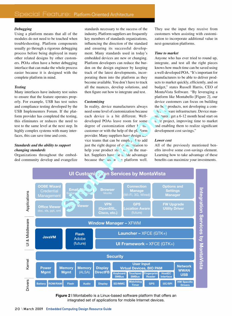
Time to marketAnyone who has ever tried to round up, integrate, and test all the right pieces knows how much time can be saved using a well-developed POA. “It’s important for manufacturers to be able to deliver prod-ucts to market quickly, efficiently, and on budget,” states Russell Harris, CEO of MontaVista Software. “By leveraging a platform like Montabello [Figure 2], our device customers can focus on building the best products, not developing a com-plex software infrastructure. Device man-ufacturers get a 6-12 month head start on their project, improving time to market and enabling them to realize significant development cost savings.”
Lower costAll of the previously mentioned ben-efits involve some cost-savings element. Learning how to take advantage of these benefits can maximize your investments.
Driv
ers
Ker
nel
UI &
Mid
dle
war
eA
pp
licat
ions
UI Customization Services by MontaVista
Window Manager – XFWM
Security
Integratio
n Services b
y Mo
ntaVista
OOBE WizardCredential
Management
PowerMgmt
MemoryMgmt
Memory(ALSA)
DisplayDirectFB
ConnectionManage
(Wi-Fi, 3G, Wired)
Options andSettingsManager
Email ClientExchange Connector
BrowserMozilla
Office Viewerdoc, xls, ppt, xml
Battery ROM/RAM Flash Audio Display SD/MMC GPS I2C/SPIHW Specific
DriversWatchdog
Timer
KeyboardSMBus
TouchpadSMBus
FingerprintReader
HostECInterface
JavaVMFlash
Adobe(future)
NetworkWWAN
USB
Launcher – XFCE (GTK+)
User InputVirtual Devices, BIO PAM Network
WWANUSB
UI Framework – XFCE (GTK+)
PDF Viewer VPN(OpenSSL, Cisco, etc.)
GPSLocation Aware
(future)
FW UpgradeUtility Driver
Figure 2 | Montabello is a Linux-based software platform that offers an integrated set of applications for mobile Internet devices.
Single Prin
t Only
Single Prin
t Only
Embedded Computing Design Resource Guide March 2009 / 21
Risk managementPOAs can significantly reduce risks in your design. Many customers contribute to the platform architecture and expose it to a myriad of testing and usage scenar-ios that measure the design in ways you may not have considered. The platform supplier provides an additional level of expertise that you can lean on if you run into design issues.
Customer loyaltyEvery vendor strives to develop a loyal base of customers, and POAs are an excellent way to develop that loyalty. All the benefits are evident to customers, and they show their appreciation by sticking with their suppliers. The pressure is on the suppliers to keep the platforms rel-evant and high quality.
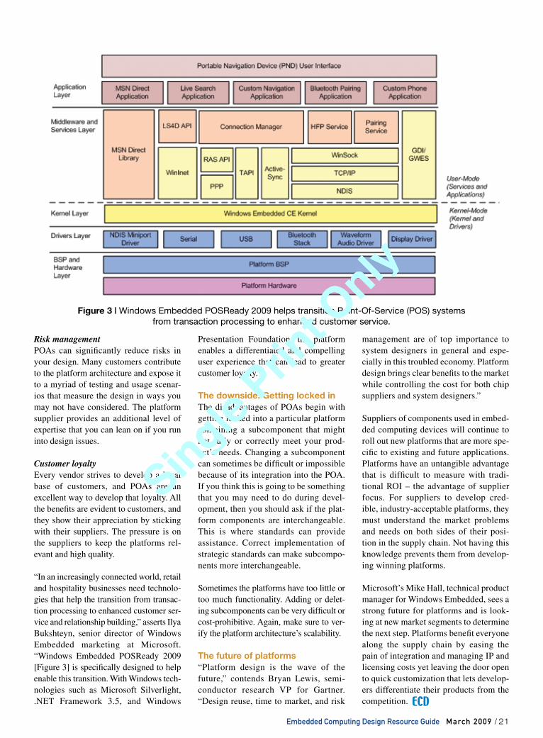
“In an increasingly connected world, retail and hospitality businesses need technolo-gies that help the transition from transac-tion processing to enhanced customer ser-vice and relationship building,” asserts Ilya Bukshteyn, senior director of Windows Embedded marketing at Microsoft. “Windows Embedded POSReady 2009 [Figure 3] is specifically designed to help enable this transition. With Windows tech-nologies such as Microsoft Silverlight, .NET Framework 3.5, and Windows
Presentation Foundation, the platform enables a differentiated and compelling user experience that can lead to greater customer loyalty.”
The downside: Getting locked inThe disadvantages of POAs begin with getting locked into a particular platform containing a subcomponent that might not fully or correctly meet your prod-uct’s needs. Changing a subcomponent can sometimes be difficult or impossible because of its integration into the POA. If you think this is going to be something that you may need to do during devel-opment, then you should ask if the plat-form components are interchangeable. This is where standards can provide assistance. Correct implementation of strategic standards can make subcompo-nents more interchangeable.
Sometimes the platforms have too little or too much functionality. Adding or delet-ing subcomponents can be very difficult or cost-prohibitive. Again, make sure to ver-ify the platform architecture’s scalability.
The future of platforms“Platform design is the wave of the future,” contends Bryan Lewis, semi-conductor research VP for Gartner. “Design reuse, time to market, and risk
management are of top importance to system designers in general and espe-cially in this troubled economy. Platform design brings clear benefits to the market while controlling the cost for both chip suppliers and system designers.”
Suppliers of components used in embed-ded computing devices will continue to roll out new platforms that are more spe-cific to existing and future applications. Platforms have an untangible advantage that is difficult to measure with tradi-tional ROI – the advantage of supplier focus. For suppliers to develop cred-ible, industry-acceptable platforms, they must understand the market problems and needs on both sides of their posi-tion in the supply chain. Not having this knowledge prevents them from develop-ing winning platforms.
Microsoft’s Mike Hall, technical product manager for Windows Embedded, sees a strong future for platforms and is look-ing at new market segments to determine the next step. Platforms benefit everyone along the supply chain by easing the pain of integration and managing IP and licensing costs yet leaving the door open to quick customization that lets develop-ers differentiate their products from the competition.
Figure 3 | Windows Embedded POSReady 2009 helps transition Point-Of-Service (POS) systems from transaction processing to enhanced customer service.
Single Prin
t Only
Single Prin
t Only
Chip and board debugging
22 \ March 2009 Embedded Computing Design Resource Guide
Featu
re
The widespread integration of USB into embedded applications presents many developers with the challenge of using this protocol for the first time. The com-plexity of USB can mask problems, leav-ing issues that are difficult to detect and isolate when a USB device misbehaves.
USB protocol analyzers allow engineers to gain greater visibility into the bus and help them quickly pinpoint the exact nature of a bug, whether it is in the physi-cal, electrical, or protocol layer. Exploring how a USB protocol analyzer can be used to debug potential problems encountered in USB development shows how this can be accomplished.
Comparing tool optionsFaced with a wide selection of debug-ging tools such as logic analyzers, oscil-loscopes, and protocol analyzers, finding the ideal debugging tool can be a daunting task. Fortunately, the complexity of USB guides the choice of a suitable debugging solution.
As a result of this complexity, tools like logic analyzers or oscilloscopes may be limited by their low-level view, making
it difficult to sort through large amounts of serial data. On the contrary, protocol analyzers can nonintrusively monitor the bus, view data as packets, and cap-ture higher-level protocol-specific data in large volumes.
The setup for capturing USB data is a straightforward process. In Figure 1, the USB analyzer is connected in-line between the target host and the target device to nonintrusively capture data. While the target host and target device
Protocol analyzers simplify USB debuggingBy Etai Bruhis
USB devices look pretty simple to use – at least when they’re
working correctly. Embedded engineers need the right set
of tools to manage the details of proper device operation.
The following examples show how USB protocol analyzers
can do just that.
Special Feature
Single Prin
t Only
Single Prin
t Only
communicate with one another, the ana-lyzer logs all of the bus traffic. Some ana-lyzers store this data and display it once the capture is complete; others display and analyze the data in real time, as it is occurring on the bus.
In contrast with scopes and logic analyzers, USB capture software can display detailed information such as time stamp, device and endpoint address, Packet Identifiers (PIDs), and data in a human-readable for-mat. The software also includes search and/or filter features to help developers quickly locate data of interest within a large amount of data.
The following examples demonstrate how a USB protocol analyzer can be used to help identify common problems in USB development.
USB data validityUSB employs two error-checking meth-ods to ensure that data is sent correctly. A Cyclic Redundancy Check (CRC) is sent with all data transmissions to validate data integrity within a packet.
In addition, a toggle bit is encoded in the data packet’s PID to guarantee that packets are sent in the correct sequence. Correct data sequencing is especially important when attempting to transfer large files across multiple independent USB transmissions.
When transferring data over multiple packets, the data PID typically toggles between DATA0 and DATA1 on each consecutive successful transmission. As data is successfully transmitted, imply-ing that the CRC is valid, the receiver acknowledges (ACK) the data, and both transmitter and receiver toggle their DATA bit. However, if there is a data error and the CRC check fails, the receiver will not reply with an ACK, and the transmitter will resend the data with the same toggle bit. The transmitter will continue to resend the same data with the same toggle bit until the receiver acknowledges its reception.
In some cases, the data is sent correctly, but the ACK handshake gets corrupted on the bus. When this occurs, the receiver
Figure 1 | In a typical device configuration for capturing USB data, the USB analyzer is connected between the target host and target device.
MEN Micro, Inc.24 North Main Street Ambler, PA 19002Tel: 215.542.9575E-mail: [email protected]
www.ESM-express.com
Finally...a complete mission-criticalcomputer on a plug-in module
XM50 with MPC8548 1.5 GHz,2 GB ECC RAM, Gb Ethernet, USB,SATA, PCI Express® x8.
Robust ESMexpress® Standard-40°C to +85°C operating temperature,max. 12 W power dissipation, onlynon-socketed components.
ANSI-VITA 59 (in process)EMC-proof housing for conduction& convection cooling, shock &vibration resistant connectors,compact 95 mm x 125 mm format.
Test the new COM alternative onour XC1 ATX carrier board.
When it comes to rugged boardsand systems for harsh, mobile andmission-critical environments,nobody delivers like MEN Micro!
MEN Micro’s ESMexpress® COM:Rugged PowerPC®
March 3-5, 2009Hall 12, Booth 545
MEN-F-5698 XM50 ECD.qxd 1/23/09 11:53 AM Page 1
Single Prin
t Only
Single Prin
t Only
24 \ March 2009 Embedded Computing Design Resource Guide
thinks that the data was sent properly and updates its toggle bit, but the transmitter does not actually know if the data was received correctly. Therefore, the trans-mitter will send the same data with the same toggle bit. Since the toggle bit has not changed, the receiver assumes that this is a retransmission of the same data and silently ignores the data. The receiver will then ACK, causing the transmitter’s toggle bit to update correctly.
Finding problems in data bit toggling Incorrectly handling the toggle bit is a com-mon USB problem that is hard to identify because the symptoms do not necessarily render a device unusable. A device may simply appear to have a reduced through-put, or individual data transmissions may be dropped. Without the aid of a hardware protocol analyzer, it is nearly impossible to deduce that improper data toggling is the cause of the problem.
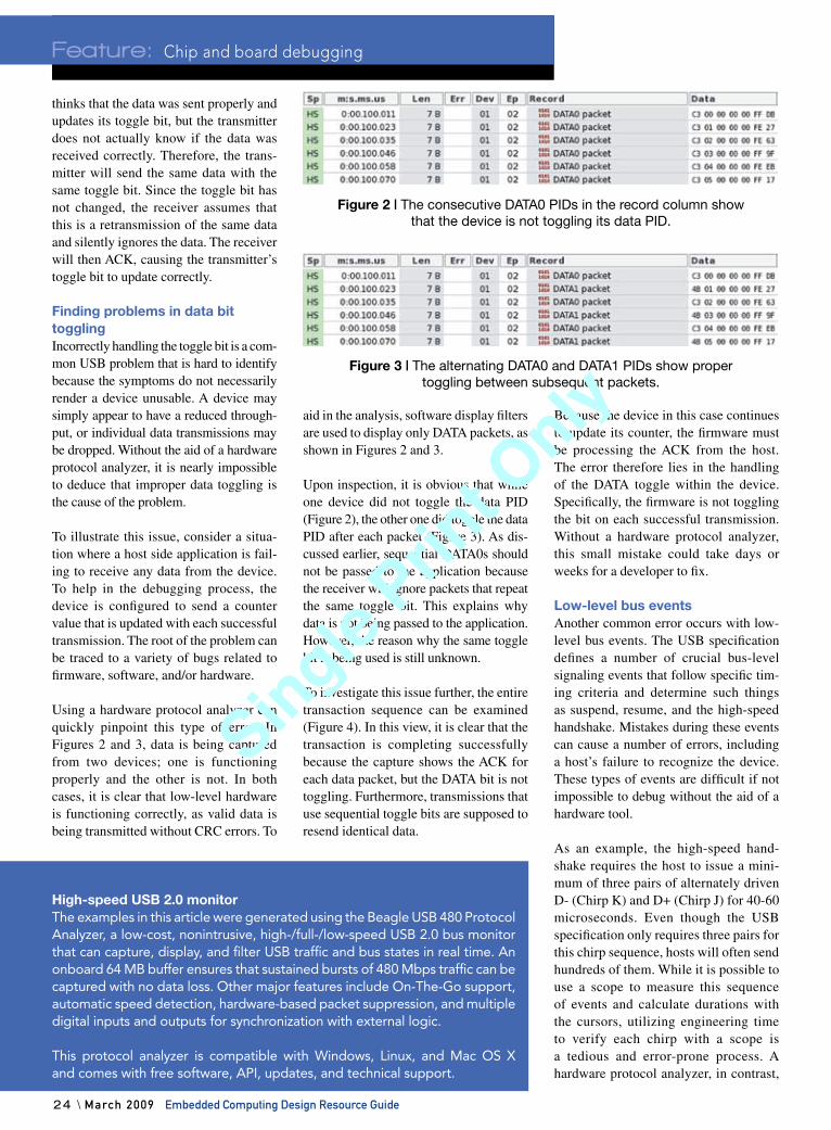
To illustrate this issue, consider a situa-tion where a host side application is fail-ing to receive any data from the device. To help in the debugging process, the device is configured to send a counter value that is updated with each successful transmission. The root of the problem can be traced to a variety of bugs related to firmware, software, and/or hardware.
Using a hardware protocol analyzer can quickly pinpoint this type of error. In Figures 2 and 3, data is being captured from two devices; one is functioning properly and the other is not. In both cases, it is clear that low-level hardware is functioning correctly, as valid data is being transmitted without CRC errors. To
aid in the analysis, software display filters are used to display only DATA packets, as shown in Figures 2 and 3.
Upon inspection, it is obvious that while one device did not toggle the data PID (Figure 2), the other one did toggle the data PID after each packet (Figure 3). As dis-cussed earlier, sequential DATA0s should not be passed to the application because the receiver will ignore packets that repeat the same toggle bit. This explains why data is not being passed to the application. However, the reason why the same toggle bit is being used is still unknown.
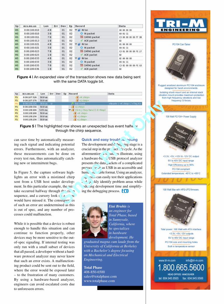
To investigate this issue further, the entire transaction sequence can be examined (Figure 4). In this view, it is clear that the transaction is completing successfully because the capture shows the ACK for each data packet, but the DATA bit is not toggling. Furthermore, transmissions that use sequential toggle bits are supposed to resend identical data.
Because the device in this case continues to update its counter, the firmware must be processing the ACK from the host. The error therefore lies in the handling of the DATA toggle within the device. Specifically, the firmware is not toggling the bit on each successful transmission. Without a hardware protocol analyzer, this small mistake could take days or weeks for a developer to fix.
Low-level bus events Another common error occurs with low-level bus events. The USB specification defines a number of crucial bus-level signaling events that follow specific tim-ing criteria and determine such things as suspend, resume, and the high-speed handshake. Mistakes during these events can cause a number of errors, including a host’s failure to recognize the device. These types of events are difficult if not impossible to debug without the aid of a hardware tool.
As an example, the high-speed hand-shake requires the host to issue a mini-mum of three pairs of alternately driven D- (Chirp K) and D+ (Chirp J) for 40-60 microseconds. Even though the USB specification only requires three pairs for this chirp sequence, hosts will often send hundreds of them. While it is possible to use a scope to measure this sequence of events and calculate durations with the cursors, utilizing engineering time to verify each chirp with a scope is a tedious and error-prone process. A hardware protocol analyzer, in contrast,
Feature: Chip and board debugging
Figure 2 | The consecutive DATA0 PIDs in the record column show that the device is not toggling its data PID.
Figure 3 | The alternating DATA0 and DATA1 PIDs show proper toggling between subsequent packets.
High-speed USB 2.0 monitorThe examples in this article were generated using the Beagle USB 480 Protocol Analyzer, a low-cost, nonintrusive, high-/full-/low-speed USB 2.0 bus monitor that can capture, display, and filter USB traffic and bus states in real time. An onboard 64 MB buffer ensures that sustained bursts of 480 Mbps traffic can be captured with no data loss. Other major features include On-The-Go support, automatic speed detection, hardware-based packet suppression, and multiple digital inputs and outputs for synchronization with external logic.
This protocol analyzer is compatible with Windows, Linux, and Mac OS X and comes with free software, API, updates, and technical support.
Single Prin
t Only
Single Prin
t Only
can save time by automatically measur-ing each signal and indicating potential errors. Furthermore, with an analyzer, these measurements can be done on every test run, thus automatically catch-ing new or intermittent bugs.
In Figure 5, the capture software high-lights an error with a mistimed chirp sent from a USB host under develop-ment. In this particular example, the mis-take occurred halfway through the chirp sequence, and a cursory look on a scope would have missed it. The consequences of such an error are undetermined as this is out of spec, and any number of pro-cesses could malfunction.
While it is possible that a device is robust enough to handle this situation and can continue to function properly, other devices may be more sensitive to the out-of-spec signaling. If internal testing was only run with a small subset of devices that all passed, a developer without a hard-ware protocol analyzer may never know that such an error exists. A malfunction-ing product could be sent out to the field, where the error would be exposed later – to the frustration of many customers. By using a hardware-based analyzer, engineers can avoid escalated costs due to unforeseen errors.
Quick and easy troubleshootingThe development and debugging stage is a crucial step in the product life cycle. As the aforementioned situations illustrate, using a hardware-based USB protocol analyzer presents the data packets of a complicated protocol such as USB in an accessible and human-readable format. Using an analyzer, engineers can easily test their applications and quickly identify problem areas while reducing development time and simplify-ing the debugging process.
Figure 4 | An expanded view of the transaction shows new data being sent with the same DATA toggle bit.
Figure 5 | The highlighted row shows an unexpected bus event halfway through the chirp sequence.
Etai Bruhis is an engineer for Total Phase, based in Sunnyvale, California, where he specializes in hardware development. He
graduated magna cum laude from the University of California at Berkeley with a Bachelor’s degree focusing on Mechanical and Electrical Engineering.
Total [email protected]
Single Prin
t Only
Single Prin
t Only
Core IP licensing
26 \ March 2009 Embedded Computing Design Resource Guide
Featu
re
Software Bill of Materials improves Intellectual Property managementBy Mahshad Koohgoli, PhD, and Sorin Cohn-Sfetcu, PhD
Software has become a ubiquitous part of cell phones, cameras, computers, and other mass-distributed consumer products. This pervasiveness can hinder embedded system developers given that software development costs sometimes outweigh those of hardware development, and prod-uct support issues are more often related to software rather than hardware problems.
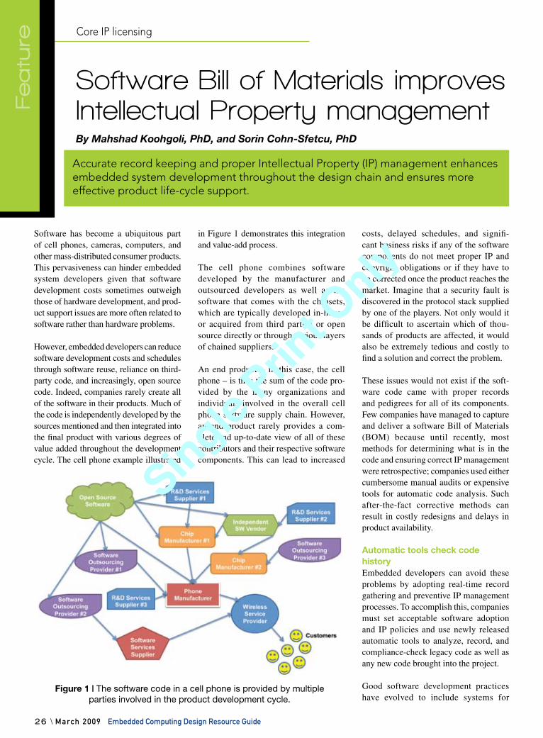
However, embedded developers can reduce software development costs and schedules through software reuse, reliance on third-party code, and increasingly, open source code. Indeed, companies rarely create all of the software in their products. Much of the code is independently developed by the sources mentioned and then integrated into the final product with various degrees of value added throughout the development cycle. The cell phone example illustrated
in Figure 1 demonstrates this integration and value-add process.
The cell phone combines software developed by the manufacturer and outsourced developers as well as the software that comes with the chipsets, which are typically developed in-house or acquired from third parties or open source directly or through various layers of chained suppliers.
An end product – in this case, the cell phone – is thus the sum of the code pro-vided by the many organizations and individuals involved in the overall cell phone software supply chain. However, an end product rarely provides a com-plete and up-to-date view of all of these contributors and their respective software components. This can lead to increased
costs, delayed schedules, and signifi-cant business risks if any of the software components do not meet proper IP and copyright obligations or if they have to be corrected once the product reaches the market. Imagine that a security fault is discovered in the protocol stack supplied by one of the players. Not only would it be difficult to ascertain which of thou-sands of products are affected, it would also be extremely tedious and costly to find a solution and correct the problem.
These issues would not exist if the soft-ware code came with proper records and pedigrees for all of its components. Few companies have managed to capture and deliver a software Bill of Materials (BOM) because until recently, most methods for determining what is in the code and ensuring correct IP management were retrospective; companies used either cumbersome manual audits or expensive tools for automatic code analysis. Such after-the-fact corrective methods can result in costly redesigns and delays in product availability.
Automatic tools check code historyEmbedded developers can avoid these problems by adopting real-time record gathering and preventive IP management processes. To accomplish this, companies must set acceptable software adoption and IP policies and use newly released automatic tools to analyze, record, and compliance-check legacy code as well as any new code brought into the project.
Good software development practices have evolved to include systems for
Figure 1 | The software code in a cell phone is provided by multiple parties involved in the product development cycle.
Special Feature
Accurate record keeping and proper Intellectual Property (IP) management enhances embedded system development throughout the design chain and ensures more effective product life-cycle support.
Single Prin
t Only
Single Prin
t Only
Embedded Computing Design Resource Guide March 2009 / 27
checking syntax, managing software versions, and tracking software bugs. Nonetheless, certain disciplines that are accepted practice in structured hardware development have yet to be adopted in software development:
An approved vendor list that con- ftains the approved components and licenses, including commercial terms, vendor history, versions, and pricing so that a developer can select compo-nents from the list without concernAutomatic notification when fsomeone tries to use code with unapproved licenses or code modules governed by incompatible licensesA BOM that fully records which fcomponents are used in the final product, including details to enable production, determine costs, identify where it can be exported, and track vendor upgrades and other post-design activities
The best approach is to make record keep-ing and source code IP management an integral part of the software development and quality assurance processes.
Automatic tools are now available to han-dle these tasks in an unobtrusive manner and with minimal training, enabling proj-ect managers to define appropriate policies for record keeping, source code adoption, and IP management. For example, tools like Protecode’s Enterprise IP Analyzer can be applied to existing (legacy) code for establishing an up-to-date map of its components and their pedigrees. Another tool, the Development IP Assistant, is inte-grated within specific development envi-ronments, where it operates unobtrusively in the background at each development workstation to detect, log, and identify in real time each piece of code brought by the developer into the respective project.
These tools check the attributes of each piece of code against the adoption and IP management policy for the project and take appropriate action according to the established policy. Furthermore, these tools provide a software BOM that enables developers and clients throughout the embedded system design chain to be fully cognizant of what is in the code and how to address support issues effectively.
Applying real-time record keeping and preventive IP management reduces development costs, avoids wasted resources in after-the-fact corrective
activities, shortens development cycles, and enhances the overall lifelong value of embedded software systems.
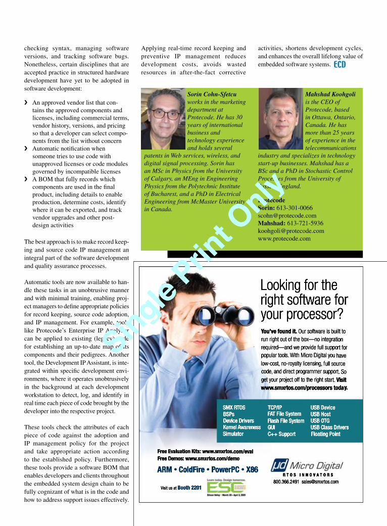
Sorin Cohn-Sfetcu works in the marketing department at Protecode. He has 30 years of international business and technology experience and holds several
patents in Web services, wireless, and digital signal processing. Sorin has an MSc in Physics from the University of Calgary, an MEng in Engineering Physics from the Polytechnic Institute of Bucharest, and a PhD in Electrical Engineering from McMaster University in Canada.
Mahshad Koohgoli is the CEO of Protecode, based in Ottawa, Ontario, Canada. He has more than 25 years of experience in the telecommunications
industry and specializes in technology start-up businesses. Mahshad has a BSc and a PhD in Stochastic Control Processes from the University of Sussex, England.
ProtecodeSorin: [email protected]: [email protected]
Single Prin
t Only
Single Prin
t Only
Programmable logic
28 \ March 2009 Embedded Computing Design Resource Guide
Featu
re
An expedient choice that bites backA major challenge for any business, par-ticularly in the current economic climate, is determining how much to invest in staff and equipment to achieve profitability goals. While overspending can wipe out potential increases in profit, underinvest-ment leaves companies ill-equipped to capitalize on market possibilities or even exposed to the risk of not achieving them.
Good business is all about finding the right investment-versus-results balance, mak-ing informed choices, and working toward fulfilling the company’s needs in smarter
ways. For the most part, companies both large and small accomplish this balancing act successfully. This frees them to focus on fine-tuning the corporate machine so that its long-term performance matches all those squiggly PowerPoint graphs busi-ness leaders are so fond of.
But in the electronics design industry, the rise of programmable devices such as FPGAs has unearthed an aberration in this normally sensible industry behavior. That quirk comes as a result of the FPGA development hardware and tools selection process, in which the usually thorough considerations of cost versus results,
long-term implications, and workflow efficiency often take a holiday and are replaced by an equipment choice based on short-term expediency.
That convenient and often impulsive choice is a basic FPGA development board that costs about $49 and is sup-ported by free development tools from the FPGA device vendor.
The cost of convenienceAlthough a $49 FPGA development board is undeniably attractive, it is nonetheless a curious and risky choice when placed in the framework of professional product design economics.
For example, say that a new product has a development cost of at least $1 million as well as potential revenue of more than $10 million, and is being designed by an engineer with a salary of $100,000 – not uncommon figures in today’s industry. Considering that an extremely critical part of this multimillion-dollar develop-ment is consigned to a system investment of $49, these figures look somewhat mis-balanced and even disturbing.
While it appears that the usual checks and balances failed in this case, they prob-ably didn’t; they just never happened, perhaps because a designer opportunis-tically decided that the $49 board could
Low-cost FPGA development boards are a convenient option
when starting a new project, but that choice carries a sting
in its tail. These boards automatically constrain engineers’
design options before they even start, forcing them to design
in a fixed and predefined way that ultimately costs more
money. As an alternative, designers should consider using a
vendor-independent hardware development system that also
communicates with the design software, resulting in a flexible,
real-time development system that does not stifle innovation
by restricting choices.
The high price of low-cost FPGA development boardsBy Rob Evans
Special FeatureSoftware
Single Prin
t Only
Single Prin
t Only
do the job, given that it has a suitable FPGA device, some useful peripherals, and a bunch of external connectors. The matching design tool set is a free down-load, so by making this quick decision, the designer can get cracking on embed-ded hardware development and embed-ded software developers can get one step closer to testing on real hardware.
On the surface this might seem like a rea-sonable solution to an immediate need, but in a professional design project where thousands or even millions of dollars are at risk, that unchecked decision carries a sting in its tail. Along with the quality limitations one might expect from a $49 piece of development hardware, the real “gotcha” is that the range of possible design choices is vastly reduced by the built-in constraints of that system. These limitations are likely to cause costly design compromises and delays.
One constraint is the fixed FPGA device on the board, which narrows the design path to that device family and vendor. An initial decision of selecting a device that has excess capacity means engineers won’t run out of gates or I/O, but all other device capabilities and features must be accurately predicted before serious design can begin.
If designers get that choice wrong – the device turns out to be too slow, uses too much power, needs a hard-coded processor or DSP, or has been superseded – there’s no other option but to look for an alterna-tive device and a new development board. The new board might only cost another $49, but little of the existing design work can be transferred to the new device. This forces a substantial redesign and a costly delay in project development.
That scenario assumes that designers can source a suitable alternative device from the same vendor, but the situation is even worse if the only viable option is an FPGA from a different vendor. In this case, the incompatibility of the new device architecture means a total rede-sign and additional delays and cost. And all this time, the embedded software engineers are still waiting for the embed-ded hardware to arrive.
Another perhaps less obvious constraint is the free proprietary tool chain provided by FPGA vendors. While these tools are developed to support the vendor’s prod-ucts and encourage sales, they are under-standably devoid of support for competi-tors’ products. So if engineers change the FPGA device supplier to solve their design problems, they will also need to adapt to a new set of tools and methodologies.
All these factors add up: Designers have much less chance finding an optimal design solution; the change in device type forces a substantial redesign; switch-ing vendors requires that designers learn new tools and methodologies; and above all, the outcome of a design project that potentially involves millions of dollars is placed at risk. In short, what was an expedient and possibly impulsive choice of development hardware turns out to be a decision that can severely compro-mise engineers’ ability to explore design options for that project.
A sticky issue In practice, the creeping truth is that the $49 approach has also created a strong motivation for designers to stick with that particular vendor and device family to avoid extra work and delays. The more designers use devices and IP from that supplier in subsequent designs, the more their collective design resources become narrowly locked to that vendor.
This means that the lack of design choice within a given project and the compromises it introduces spread virally through future designs. Reusing vendor-centric designs in subsequent projects narrows the possibili-ties from the beginning, so engineers tend to adapt the design to suit the vendor’s FPGA rather than selecting an FPGA that best suits the design, effectively locking into one restrictive design path.
It’s also likely that engineers source IP cores from the device vendor as a conve-nient kick start to their designs. That IP is only useful with a specific range of FPGA devices from that particular vendor, so it is stuck to a reduced range of silicon. This sticky IP compounds the issue of limited design choice by stopping designers from jumping between devices supplied by
Single Prin
t Only
Single Prin
t Only
30 \ March 2009 Embedded Computing Design Resource Guide
Feature: Programmable logic
different vendors when they are explor-ing design options.
The short of it is that by taking the expedi-ent path of a low-cost development board in the face of established equipment selec-tion criteria, designers create a restricted vendor-sticky FPGA design environment. This environment automatically constrains the design options before the project starts, forces engineers to design in a fixed and predefined way, and devalues the design IP for future projects.
FPGAs change prioritiesSo why is it that rational, intelligent design engineers frequently adopt an approach that restricts their ability to design and places critical projects at risk?
The idea that this is a normal or accept-able way of working probably harks back to the early days of implementing FPGAs, which at the time were only regarded as a convenient and efficient host for large amounts of supporting glue logic. In this case, the decision to use an FPGA was probably made late in the design cycle, the functional value of
that logic was low, and the need to reuse it was minimal.
As FPGA design evolved into a System-on-Chip (SoC) approach, where more functionally critical elements such as pro-cessors, memory, and data processing are implemented in an FPGA, the device and embedded hardware design became fun-damentally important elements. The deci-sion of which device to use was critical and came early in the design cycle, and the design IP it hosted represented a sig-nificant and valuable design investment. Design choices and design reuse became important for embedded hardware.
Today, the role of FPGAs has advanced to the point where they have become the core or central platform for a design. This is the next step beyond an SoC approach, where along with hosting high-level functions, an FPGA acts as the interfac-ing fabric for the design’s hard and soft elements. A processor, memory, or DSP might be implemented as a soft core, physical hardware, or both, while repro-grammable layers hosted by the FPGA stitch it all together.
The key differentiating elements of prod-uct designs are now defined in both soft-ware and programmable hardware. All of this is critically influenced by the FPGA capabilities and the IP it hosts, so an approach that was acceptable in the days when FPGA-based simple glue logic was added as an afterthought is no longer valid. The need for a free range of choices for design exploration is now critical, and the cost implication of not having those choices is huge.
The question is, with thousands of dollars or more at stake, can engineers afford to take the risk of adopting a cheap FPGA development board and all it implies?
Investing in design freedomWhat’s needed is an FPGA development system that does not impose these limita-tions and design constraints. Ideally, this would be a reconfigurable development board that can host any device through a system of plug-in FPGA daughterboards (see Figure 1). The collection of daughter-boards could be added to as needed, pro-gressively increasing the range of device choices at hand during the design process.
Figure 1 | Investing in a smart, reconfigurable development board that features plug-in FPGA boards and peripheral hardware delivers long-term dividends.
Single Prin
t Only
Single Prin
t Only
Embedded Computing Design Resource Guide March 2009 / 31
The physical hardware aspect of embed-ded development is then independent of the type of FPGA and its vendor. This concept can be extended to hardware peripheral boards, where the develop-ment board offers a plug-in system for common peripheral stages such as LCD screens, I/O interfaces, or audio/visual signal conditioning. This can also include matching IP, making it fast and easy to move from one peripheral to another or to incorporate that hardware in the final design.
If that system offers a healthy range of expansion connectors and is built to a level of quality that reflects its impor-tance, as opposed to built down to a low price, the hardware is then in place for an unrestricted approach to design.
The next step is exploiting that device freedom by removing the same con-straints in the FPGA design tools. This can be done using a system of targeted drivers and constraint files that discon-nect the embedded hardware design itself from the device it’s hosted on. In this way, a new constraint file is simply loaded when the FPGA device is changed, the design source is still valid, and little or no redesign is required.
The result is an FPGA development system that opens the door to a vastly extended range of device and IP pos-sibilities. The ability to change devices with minimal redesign means the final choice can be made much later in the design cycle when its requirements are fully known. Sticky IP, while still locked to certain devices, no longer constrains the current or future design path.
Most importantly, the quality, flexibility, and longevity of the FPGA development system reflect the importance and invest-ment of the larger product development process. The financial risk of a restricted design choice is eliminated, and embed-ded developers are free to explore and choose the best possible design options for what is now a crucial part of project development.
Rob Evans is technical editor at Altium Limited, based in New South Wales, Australia. He has more than 20 years of experience in the electronics design and publishing industry, including several years as the technical editor for Electronics Australia. Rob studied Electronic Engineering at the Royal Melbourne Institute of Technology.
Altium Limited+61 2 8986 4400
Single Prin
t Only
Single Prin
t Only
Current buzz indicates that multicore and virtualization are the next move for RTOS vendors. However, in taking a closer look at the market, it appears that less than 10 percent of today’s designs require the overkill provided by multicore or virtualization.
Certainly, these offerings have a place in particular applications and specific industries; however, designers seem to continually chase the latest and great-est fads before the overall industry has maximized previous trends. Consider the following challenges yet to be solved by embedded designers and vendors:
Many companies are still struggling fwith moving from Assembly language to C. Some designers are moving from 8-bit to 32-bit processors, skipping 16 bits and still using Assembly language. Because 32-bit processors open a whole new world of possibilities, migrating to a high-level language, using an RTOS, and buying COTS products are more sensible choices.Approximately 45 percent of fproducts today either don’t use an RTOS or are still roll-your-own even though a commercial RTOS has substantial time-to-market advantages. A 2008 Embedded
Market Forecasters survey of RTOS users revealed that 44.3 percent of projects that used an in-house RTOS and 41.4 percent of those that used open source were completed late by an average of three months.Is processor performance exhausted fto the extent that multicores are a must? Performance bottlenecks in most cases are due to memory, not processors.As microprocessors become more fcomplex, the visibility into their inner workings diminishes. Debuggers are great at proving algorithms and debugging the system statically (a breakpoint must be hit to step through code) but fall short with dynamic systems. Instead of adding more processor cores, semiconductor manufacturers need to add logic that can greatly enhance debugging.Code reuse is an extremely fimportant design, time-to-market, and quality issue that is often all but ignored. This also applies to semiconductor vendors who don’t always use the same hardware blocks when developing different chips. Two chips within the same family from the same manufacturer typically use two different USB device controllers. How many different SPI controllers, UARTs, and timers do designers need?
Software
32 \ March 2009 Embedded Computing Design Resource Guide
Featu
re
Trends are good for press, not necessarily for socketsBy Jean J. Labrosse
It’s easy for Real-Time Operating System (RTOS) providers
to jump on the multicore and virtualization bandwagons.
However, before going off in another direction, vendors
should consider if these trends represent the requirements
of most designs and ask themselves if existing design/
performance issues have been sufficiently satisfied. Jean
explains why “not yet” is the correct answer to this question.Single Prin
t Only
Single Prin
t Only
While it is important for designers to con-sider the future, it is even more impera-tive that they first close the loop on their own design/performance issues and determine if they are using the right tools and becoming more efficient at designing reliable systems.
Although designers will always be inter-ested in the next best thing that can cata-pult the industry forward, they must make sure that the majority of design needs are met before taking too long to get designs out the door. Building or rebuilding a product with the complexity involved in multicore and virtualization designs is a daunting task. Instead, developing quality, user-friendly code, reusing code whenever possible, and following a pattern of logical steps for growth are the best design strate-gies, at least for now.
New events scheduled this month!
VISIT US ONLINE FOR DETAILS AND FREE REGISTRATION:
ELive Knowledge Webcasts
ecast.opensystemsmedia.com
Embedded Computing Design Resource Guide March 2009 / 33
Jean J. Labrosse is president of Micrium, based in Weston, Florida. In addition to serving as a regular speaker at the Embedded Systems Conferences, he has written numerous articles for magazines as well as two books, MicroC/OS-II: The Real-Time Kernel and Embedded Systems Building Blocks: Complete and Ready-to-Use Modules in C. Jean has a BSEE and an MSEE from the University of Sherbrooke, Quebec, Canada.
Micrium954-217-2036
Single Prin
t Only
Single Prin
t Only
For more information, contact: [email protected] RSC# 38782 @ www.embedded-computing.com/rsc
Fidus Systems Inc. 900 Morrison Drive, Suite 203 • Ottawa, Ontario K2H 8K7 Canada866-883-4387www.fidus.com
Fidus Systems develops electronic products for a wide range of industries including aerospace, defense, consumer, medical, industrial, semiconductors and telecommunica-tions. Whether it is turnkey product development or tar-geted assistance on a project, Fidus has the bench strength to offer highly qualified engineers. As a design partner, Fidus offers companies greater flexibility and capability in their product development with access to the expertise, process and tools to successfully move their concepts to revenue-generating products. Fidus uses proven product development and design methodologies combined with a comprehensive suite of tools. Fidus has delivered on more than 700 products and projects for 140 customers across North America.
Electronic Product Development
System design and architecture ›Hardware design ›DSP/FPGA/ASIC design ›Software/firmware design ›Wireless/RF design ›PCB layout ›Signal integrity/EMC ›Prototype design and testing ›Regulatory compliance ›Environmental and reliability ›RoHS compliance/component obsolescence ›
CAPABILITIES
Design services
Embedded Computing Design Resource Guide
Embedded Computing Design Resource GuideD
esig
n ai
ds
For more information, contact: [email protected] RSC# 41324 @ www.embedded-computing.com/rsc
Radian Heatsinks2160 Walsh Avenue • Santa Clara, CA 95050408-988-6200www.radianheatsinks.com
The INM-PCU Series of copper round pin BGA heatsinks includes high efficiency cooling products that are ideal for omni-directional airflow.
These devices mount with EZ Snap™ Mounting Clips and/or Thermal Tape to provide optimum cooling for various package sizes and airflow. These off-the-shelf, high effi-ciency solutions are easy to install and require no special board modifications or complex assemblies.
INM-PCU Series
High efficiency copper round pin design provides low pressure-drop ›characteristicsConstructed of Forged CU1100 Oxygen-Free Copper for optimum ›heat transferIdeal for omni-directional airflow ›Designed specifically for BGAs and other surface mount packages ›Optional EZ Snap Mounting Clip is made of UL94-V0 Rated Nylon ›Use Clip Tool HS8063 to attach or remove heatsink assembly directly ›to BGA Chip Finished with clear anti-oxidation finish ›Selected Clip and Thermal Pad Options are pre-assembled at the ›factory
FEATURES
Thermal management
34 \ March 2009 Embedded Computing Design Resource Guide
Single Prin
t Only
Single Prin
t Only
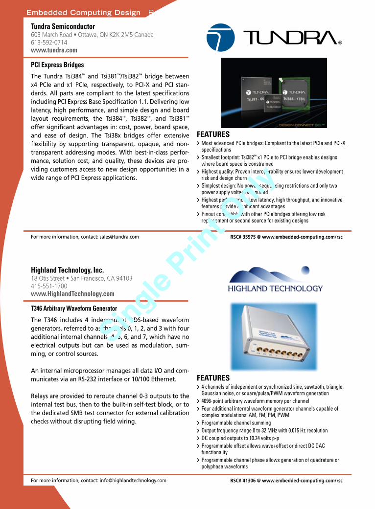
Embedded Computing Design Resource Guide
Embedded Computing Design Resource Guide
For more information, contact: [email protected] RSC# 35975 @ www.embedded-computing.com/rsc
Tundra Semiconductor603 March Road • Ottawa, ON K2K 2M5 Canada613-592-0714www.tundra.com
The Tundra Tsi384™ and Tsi381™/Tsi382™ bridge between x4 PCIe and x1 PCIe, respectively, to PCI-X and PCI stan-dards. All parts are compliant to the latest specifications including PCI Express Base Specification 1.1. Delivering low latency, high performance, and simple design and board layout requirements, the Tsi384™, Tsi382™, and Tsi381™ offer significant advantages in: cost, power, board space, and ease of design. The Tsi38x bridges offer extensive flexibility by supporting transparent, opaque, and non- transparent addressing modes. With best-in-class perfor-mance, solution cost, and quality, these devices are pro-viding customers access to new design opportunities in a wide range of PCI Express applications.
®
PCI Express Bridges
Most advanced PCIe bridges: Compliant to the latest PCIe and PCI-X ›specificationsSmallest footprint: Tsi382 › ™ x1 PCIe to PCI bridge enables designs where board space is constrainedHighest quality: Proven interoperability ensures lower development ›risk and design churnSimplest design: No power sequencing restrictions and only two ›power supply voltages requiredHighest performance: Low latency, high throughput, and innovative ›features provide significant advantagesPinout compatible with other PCIe bridges offering low risk ›replacement or second source for existing designs
FEATURES
PCI Express
For more information, contact: [email protected] RSC# 41306 @ www.embedded-computing.com/rsc
Highland Technology, Inc.18 Otis Street • San Francisco, CA 94103415-551-1700www.HighlandTechnology.com
The T346 includes 4 independent DDS-based waveform generators, referred to as channels 0, 1, 2, and 3 with four additional internal channels, 4, 5, 6, and 7, which have no electrical outputs but can be used as modulation, sum-ming, or control sources.
An internal microprocessor manages all data I/O and com-municates via an RS-232 interface or 10/100 Ethernet.
Relays are provided to reroute channel 0-3 outputs to the internal test bus, then to the built-in self-test block, or to the dedicated SMB test connector for external calibration checks without disrupting field wiring.
T346 Arbitrary Waveform Generator
4 channels of independent or synchronized sine, sawtooth, triangle, ›Gaussian noise, or square/pulse/PWM waveform generation4096-point arbitrary waveform memory per channel ›Four additional internal waveform generator channels capable of ›complex modulations: AM, FM, PM, PWMProgrammable channel summing ›Output frequency range 0 to 32 MHz with 0.015 Hz resolution ›DC coupled outputs to 10.24 volts p-p ›Programmable offset allows wave+offset or direct DC DAC ›functionalityProgrammable channel phase allows generation of quadrature or ›polyphase waveforms
FEATURES
Waveform generator
Interfaces
Embedded Computing Design Resource Guide March 2009 / 35
Single Prin
t Only
Single Prin
t Only
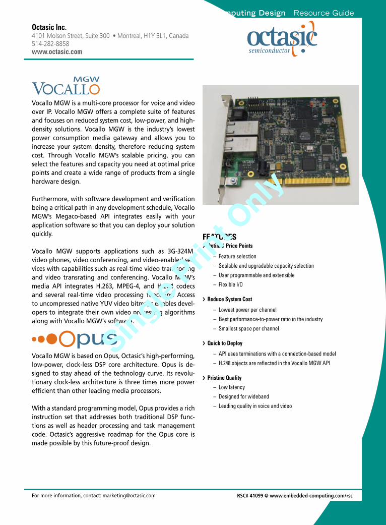
Embedded Computing Design Resource GuideDSPs
For more information, contact: [email protected]
Octasic Inc.4101 Molson Street, Suite 300 • Montreal, H1Y 3L1, Canada514-282-8858www.octasic.com
Vocallo MGW is a multi-core processor for voice and video over IP. Vocallo MGW offers a complete suite of features and focuses on reduced system cost, low-power, and high-density solutions. Vocallo MGW is the industry’s lowest power consumption media gateway and allows you to increase your system density, therefore reducing system cost. Through Vocallo MGW’s scalable pricing, you can select the features and capacity you need at optimal price points and create a wide range of products from a single hardware design.
Furthermore, with software development and verification being a critical path in any development schedule, Vocallo MGW’s Megaco-based API integrates easily with your application software so that you can deploy your solution quickly.
Vocallo MGW supports applications such as 3G-324M, video phones, video conferencing, and video-enabled ser-vices with capabilities such as real-time video transcoding and video transrating and conferencing. Vocallo MGW’s media API integrates H.263, MPEG-4, and H.264 codecs and several real-time video processing functions. Access to uncompressed native YUV video bitmaps enables devel-opers to integrate their own video processing algorithms along with Vocallo MGW’s software.
Vocallo MGW is based on Opus, Octasic’s high-performing, low-power, clock-less DSP core architecture. Opus is de-signed to stay ahead of the technology curve. Its revolu-tionary clock-less architecture is three times more power efficient than other leading media processors.
With a standard programming model, Opus provides a rich instruction set that addresses both traditional DSP func-tions as well as header processing and task management code. Octasic’s aggressive roadmap for the Opus core is made possible by this future-proof design.
Optimal Price Points ›
Feature selection –
Scalable and upgradable capacity selection –
User programmable and extensible –
Flexible I/O –
Reduce System Cost ›
Lowest power per channel –
Best performance-to-power ratio in the industry –
Smallest space per channel –
Quick to Deploy ›
API uses terminations with a connection-based model –
H.248 objects are reflected in the Vocallo MGW API –
Pristine Quality ›
Low latency –
Designed for wideband –
Leading quality in voice and video –
FEATURES
RSC# 41099 @ www.embedded-computing.com/rsc
Mic
roco
ntro
llers
and
pro
cess
ors
36 \ March 2009 Embedded Computing Design Resource Guide
Single Prin
t Only
Single Prin
t Only
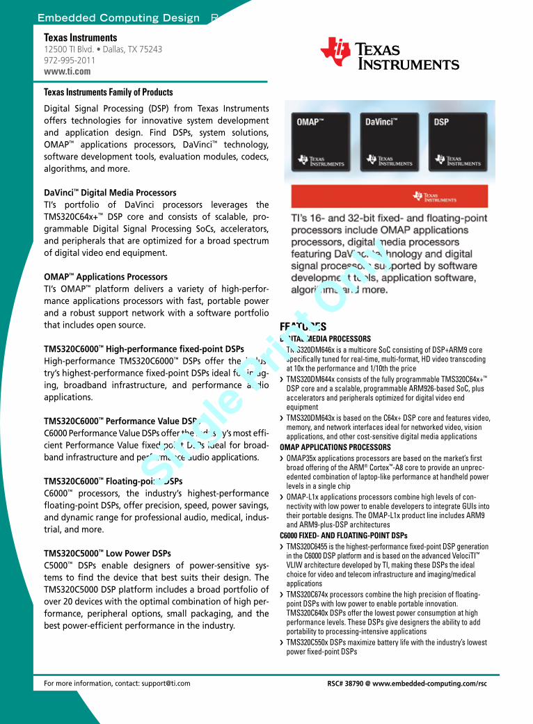
Embedded Computing Design Resource Guide DSPs
For more information, contact: [email protected]
Texas Instruments12500 TI Blvd. • Dallas, TX 75243 972-995-2011www.ti.com
Digital Signal Processing (DSP) from Texas Instruments offers technologies for innovative system development and application design. Find DSPs, system solutions, OMAP™ applications processors, DaVinci™ technology, software development tools, evaluation modules, codecs, algorithms, and more.
DaVinci™ Digital Media ProcessorsTI’s portfolio of DaVinci processors leverages the TMS320C64x+™ DSP core and consists of scalable, pro-grammable Digital Signal Processing SoCs, accelerators, and peripherals that are optimized for a broad spectrum of digital video end equipment.
OMAP™ Applications ProcessorsTI’s OMAP™ platform delivers a variety of high-perfor-mance applications processors with fast, portable power and a robust support network with a software portfolio that includes open source.
TMS320C6000™ High-performance fixed-point DSPsHigh-performance TMS320C6000™ DSPs offer the indus-try’s highest-performance fixed-point DSPs ideal for imag-ing, broadband infrastructure, and performance audio applications.
TMS320C6000™ Performance Value DSPsC6000 Performance Value DSPs offer the industry’s most effi-cient Performance Value fixed-point DSPs ideal for broad-band infrastructure and performance audio applications.
TMS320C6000™ Floating-point DSPsC6000™ processors, the industry’s highest-performance floating-point DSPs, offer precision, speed, power savings, and dynamic range for professional audio, medical, indus-trial, and more.
TMS320C5000™ Low Power DSPsC5000™ DSPs enable designers of power-sensitive sys-tems to find the device that best suits their design. The TMS320C5000 DSP platform includes a broad portfolio of over 20 devices with the optimal combination of high per-formance, peripheral options, small packaging, and the best power-efficient performance in the industry.
Texas Instruments Family of Products
DIGITAL MEDIA PROCESSORSTMS320DM646x is a multicore SoC consisting of DSP+ARM9 core ›specifically tuned for real-time, multi-format, HD video transcoding at 10x the performance and 1/10th the priceTMS320DM644x consists of the fully programmable TMS320C64x+ › ™ DSP core and a scalable, programmable ARM926-based SoC, plus accelerators and peripherals optimized for digital video end equipmentTMS320DM643x is based on the C64x+ DSP core and features video, ›memory, and network interfaces ideal for networked video, vision applications, and other cost-sensitive digital media applications
OMAP APPLICATIONS PROCESSORSOMAP35x applications processors are based on the market’s first ›broad offering of the ARM® Cortex™-A8 core to provide an unprec-edented combination of laptop-like performance at handheld power levels in a single chipOMAP-L1x applications processors combine high levels of con- ›nectivity with low power to enable developers to integrate GUIs into their portable designs. The OMAP-L1x product line includes ARM9 and ARM9-plus-DSP architectures
C6000 FIXED- AND FLOATING-POINT DSPs TMS320C6455 is the highest-performance fixed-point DSP generation ›in the C6000 DSP platform and is based on the advanced VelociTI™ VLIW architecture developed by TI, making these DSPs the ideal choice for video and telecom infrastructure and imaging/medical applicationsTMS320C674x processors combine the high precision of floating- ›point DSPs with low power to enable portable innovation. TMS320C640x DSPs offer the lowest power consumption at high performance levels. These DSPs give designers the ability to add portability to processing-intensive applicationsTMS320C550x DSPs maximize battery life with the industry’s lowest ›power fixed-point DSPs
FEATURES
RSC# 38790 @ www.embedded-computing.com/rsc
Microcontrollers and
processors
Embedded Computing Design Resource Guide March 2009 / 37
Single Prin
t Only
Single Prin
t Only
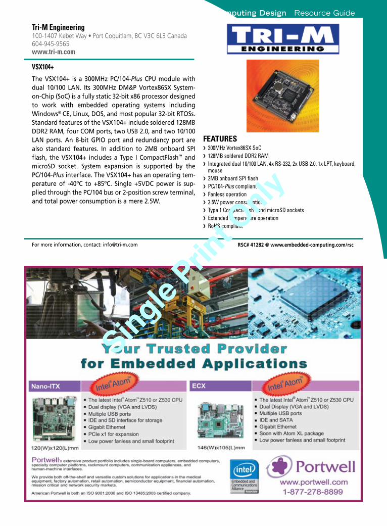
Embedded Computing Design Resource Guide
Embedded Computing Design Resource GuideM
icro
cont
rolle
rs a
nd p
roce
ssor
s
For more information, contact: [email protected] RSC# 41282 @ www.embedded-computing.com/rsc
Tri-M Engineering100-1407 Kebet Way • Port Coquitlam, BC V3C 6L3 Canada604-945-9565www.tri-m.com
The VSX104+ is a 300MHz PC/104-Plus CPU module with dual 10/100 LAN. Its 300MHz DM&P Vortex86SX System-on-Chip (SoC) is a fully static 32-bit x86 processor designed to work with embedded operating systems including Windows® CE, Linux, DOS, and most popular 32-bit RTOSs. Standard features of the VSX104+ include soldered 128MB DDR2 RAM, four COM ports, two USB 2.0, and two 10/100 LAN ports. An 8-bit GPIO port and redundancy port are also standard features. In addition to 2MB onboard SPI flash, the VSX104+ includes a Type I CompactFlash™ and microSD socket. System expansion is supported by the PC/104-Plus interface. The VSX104+ has an operating tem-perature of -40ºC to +85ºC. Single +5VDC power is sup-plied through the PC/104 bus or 2-position screw terminal, and total power consumption is a mere 2.5W.
VSX104+
300MHz Vortex86SX SoC ›128MB soldered DDR2 RAM ›Integrated dual 10/100 LAN, 4x RS-232, 2x USB 2.0, 1x LPT, keyboard, ›mouse 2MB onboard SPI flash ›PC/104- › Plus compliant Fanless operation ›2.5W power consumption ›Type 1 CompactFlash › ™ and microSD sockets Extended temperature operation ›RoHS compliant ›
FEATURES
Systems-on-Chip
38 \ March 2009 Embedded Computing Design Resource Guide
Single Prin
t Only
Single Prin
t Only
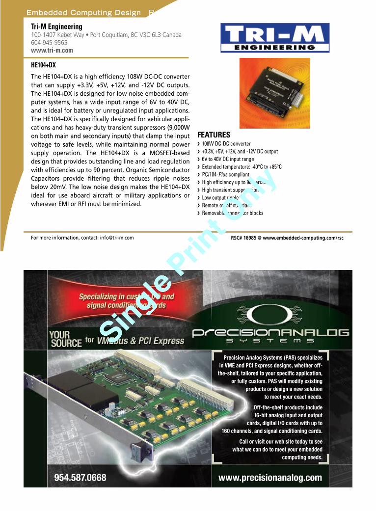
Embedded Computing Design Resource Guide
Embedded Computing Design Resource Guide Pow
er managem
ent
Precision Analog Systems (PAS) specializes in VME and PCI Express designs, whether off-
the-shelf, tailored to your specific application, or fully custom. PAS will modify existing
products or design a new solution to meet your exact needs.
Off-the-shelf products include 16-bit analog input and output
cards, digital I/O cards with up to 160 channels, and signal conditioning cards.
Call or visit our web site today to see what we can do to meet your embedded
computing needs.
www.precisionanalog.com 954.587.0668
For more information, contact: [email protected] RSC# 16985 @ www.embedded-computing.com/rsc
Tri-M Engineering100-1407 Kebet Way • Port Coquitlam, BC V3C 6L3 Canada604-945-9565www.tri-m.com
The HE104+DX is a high efficiency 108W DC-DC converter that can supply +3.3V, +5V, +12V, and -12V DC outputs. The HE104+DX is designed for low noise embedded com-puter systems, has a wide input range of 6V to 40V DC, and is ideal for battery or unregulated input applications. The HE104+DX is specifically designed for vehicular appli-cations and has heavy-duty transient suppressors (9,000W on both main and secondary inputs) that clamp the input voltage to safe levels, while maintaining normal power supply operation. The HE104+DX is a MOSFET-based design that provides outstanding line and load regulation with efficiencies up to 90 percent. Organic Semiconductor Capacitors provide filtering that reduces ripple noises below 20mV. The low noise design makes the HE104+DX ideal for use aboard aircraft or military applications or wherever EMI or RFI must be minimized.
HE104+DX
108W DC-DC converter ›+3.3V, +5V, +12V, and -12V DC output ›6V to 40V DC input range ›Extended temperature: -40°C to +85°C ›PC/104- › Plus compliant High efficiency up to 90 percent ›High transient suppression ›Low output ripple ›Remote on/off standard ›Removable connector blocks ›
FEATURES
User interfaces
Embedded Computing Design Resource Guide March 2009 / 39
Single Prin
t Only
Single Prin
t Only
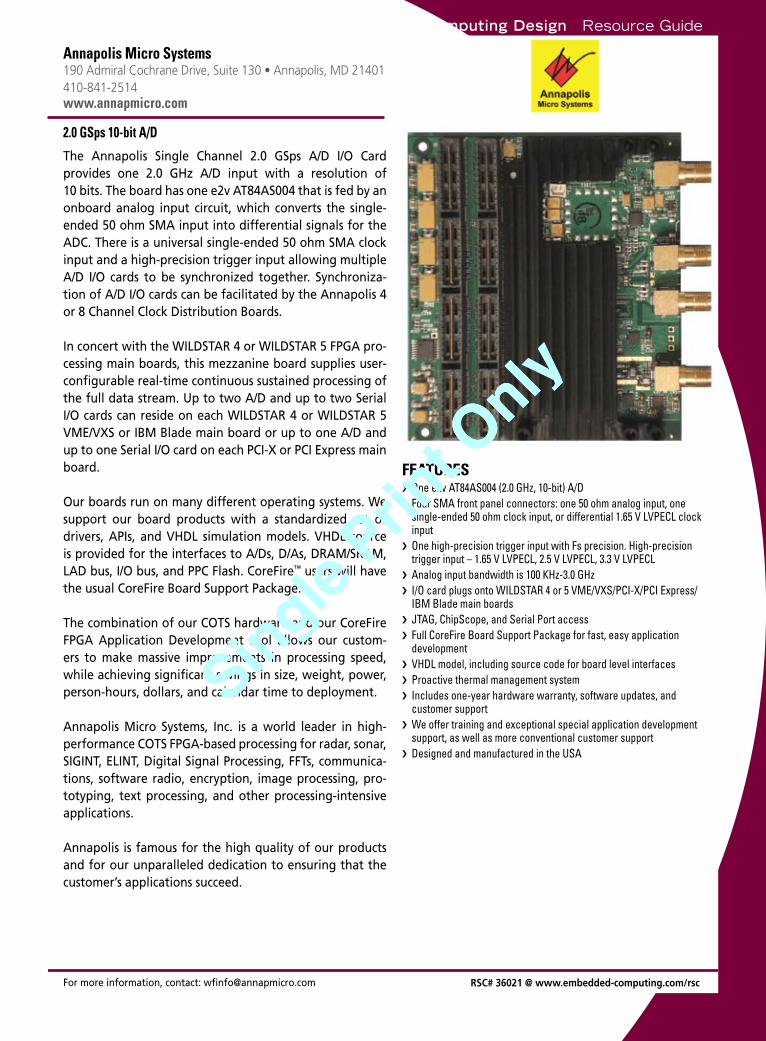
Embedded Computing Design Resource GuideP
rogr
amm
able
logi
cFPGAs
For more information, contact: [email protected]
Annapolis Micro Systems190 Admiral Cochrane Drive, Suite 130 • Annapolis, MD 21401 410-841-2514www.annapmicro.com
The Annapolis Single Channel 2.0 GSps A/D I/O Card provides one 2.0 GHz A/D input with a resolution of 10 bits. The board has one e2v AT84AS004 that is fed by an onboard analog input circuit, which converts the single- ended 50 ohm SMA input into differential signals for the ADC. There is a universal single-ended 50 ohm SMA clock input and a high-precision trigger input allowing multiple A/D I/O cards to be synchronized together. Synchroniza-tion of A/D I/O cards can be facilitated by the Annapolis 4 or 8 Channel Clock Distribution Boards.
In concert with the WILDSTAR 4 or WILDSTAR 5 FPGA pro-cessing main boards, this mezzanine board supplies user-configurable real-time continuous sustained processing of the full data stream. Up to two A/D and up to two Serial I/O cards can reside on each WILDSTAR 4 or WILDSTAR 5 VME/VXS or IBM Blade main board or up to one A/D and up to one Serial I/O card on each PCI-X or PCI Express main board.
Our boards run on many different operating systems. We support our board products with a standardized set of drivers, APIs, and VHDL simulation models. VHDL source is provided for the interfaces to A/Ds, D/As, DRAM/SRAM, LAD bus, I/O bus, and PPC Flash. CoreFire™ users will have the usual CoreFire Board Support Package.
The combination of our COTS hardware and our CoreFire FPGA Application Development tool allows our custom-ers to make massive improvements in processing speed, while achieving significant savings in size, weight, power, person-hours, dollars, and calendar time to deployment.
Annapolis Micro Systems, Inc. is a world leader in high-performance COTS FPGA-based processing for radar, sonar, SIGINT, ELINT, Digital Signal Processing, FFTs, communica-tions, software radio, encryption, image processing, pro-totyping, text processing, and other processing-intensive applications.
Annapolis is famous for the high quality of our products and for our unparalleled dedication to ensuring that the customer’s applications succeed.
2.0 GSps 10-bit A/D
One e2v AT84AS004 (2.0 GHz, 10-bit) A/D ›Four SMA front panel connectors: one 50 ohm analog input, one ›single-ended 50 ohm clock input, or differential 1.65 V LVPECL clock inputOne high-precision trigger input with Fs precision. High-precision ›trigger input – 1.65 V LVPECL, 2.5 V LVPECL, 3.3 V LVPECLAnalog input bandwidth is 100 KHz-3.0 GHz ›I/O card plugs onto WILDSTAR 4 or 5 VME/VXS/PCI-X/PCI Express/ ›IBM Blade main boardsJTAG, ChipScope, and Serial Port access ›Full CoreFire Board Support Package for fast, easy application ›developmentVHDL model, including source code for board level interfaces ›Proactive thermal management system ›Includes one-year hardware warranty, software updates, and ›customer supportWe offer training and exceptional special application development ›support, as well as more conventional customer supportDesigned and manufactured in the USA ›
FEATURES
RSC# 36021 @ www.embedded-computing.com/rsc
40 \ March 2009 Embedded Computing Design Resource Guide
Single Prin
t Only
Single Prin
t Only
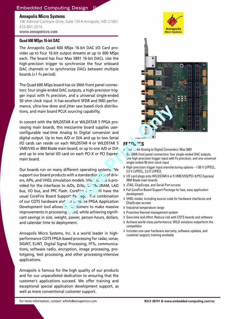
Embedded Computing Design Resource Guide Program
mab
le logicFPGAs
For more information, contact: [email protected]
Annapolis Micro Systems190 Admiral Cochrane Drive, Suite 130 • Annapolis, MD 21401 410-841-2514www.annapmicro.com
The Annapolis Quad 600 MSps 16-bit DAC I/O Card pro-vides up to four 16-bit output streams at up to 600 MSps each. The board has four Max 5891 16-bit DACs. Use the high-precision trigger to synchronize the four onboard DAC channels or to synchronize DACs between multiple boards (<1 Fs period).
The Quad 600 MSps board has six SMA front panel connec-tors: four single-ended DAC outputs, a high-precision trig-ger input with Fs precision, and a universal single-ended 50 ohm clock input. It has excellent SFDR and IMD perfor-mance, ultra-low skew and jitter saw based clock distribu-tions, and main board PCLK sourcing capability.
In concert with the WILDSTAR 4 or WILDSTAR 5 FPGA pro-cessing main boards, this mezzanine board supplies user-configurable real-time Analog to Digital conversion and digital output. Up to two A/D or D/A and up to two Serial I/O cards can reside on each WILDSTAR 4 or WILDSTAR 5 VME/VXS or IBM Blade main board, or up to one A/D or D/A and up to one Serial I/O card on each PCI-X or PCI Express main board.
Our boards run on many different operating systems. We support our board products with a standardized set of driv-ers, APIs, and VHDL simulation models. VHDL source is pro-vided for the interfaces to A/Ds, D/As, DRAM/SRAM, LAD bus, I/O bus, and PPC Flash. CoreFire users will have the usual CoreFire Board Support Package. The combination of our COTS hardware and our CoreFire FPGA Application Development tool allows our customers to make massive improvements in processing speed, while achieving signifi-cant savings in size, weight, power, person-hours, dollars, and calendar time to deployment.
Annapolis Micro Systems, Inc. is a world leader in high-performance COTS FPGA-based processing for radar, sonar, SIGINT, ELINT, Digital Signal Processing, FFTs, communica-tions, software radio, encryption, image processing, pro-totyping, text processing, and other processing-intensive applications.
Annapolis is famous for the high quality of our products and for our unparalleled dedication to ensuring that the customer’s applications succeed. We offer training and exceptional special application development support, as well as more conventional customer support.
Quad 600 MSps 16-bit DAC
Four 16-bit Analog to Digital Converters: Max 5891 ›Six SMA front panel connectors: four single-ended DAC outputs, ›one high-precision trigger input with Fs precision, and one universal single-ended 50 ohm clock inputHigh-precision trigger input manufacturing options – 1.65 V LVPECL, ›2.5 V LVPECL, 3.3 V LVPECLI/O card plugs onto WILDSTAR 4 or 5 VME/VXS/PCI-X/PCI Express/ ›IBM Blade main boardsJTAG, ChipScope, and Serial Port access ›Full CoreFire Board Support Package for fast, easy application ›developmentVHDL model, including source code for hardware interfaces and ›ChipScope accessIndustrial temperature range ›Proactive thermal management system ›Save time and effort. Reduce risk with COTS boards and software ›Achieve world-class performance; WILD solutions outperform the ›competitionIncludes one-year hardware warranty, software updates, and ›customer support; training available
FEATURES
RSC# 38791 @ www.embedded-computing.com/rsc
Embedded Computing Design Resource Guide March 2009 / 41
Single Prin
t Only
Single Prin
t Only
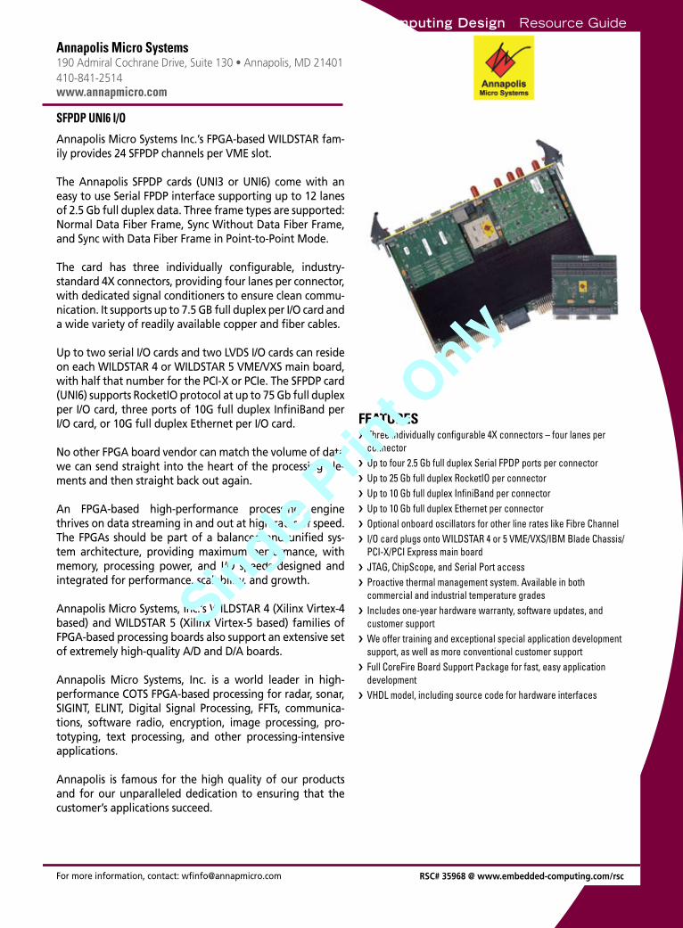
Embedded Computing Design Resource GuideP
rogr
amm
able
logi
cFPGAs
For more information, contact: [email protected]
Annapolis Micro Systems190 Admiral Cochrane Drive, Suite 130 • Annapolis, MD 21401 410-841-2514www.annapmicro.com
Annapolis Micro Systems Inc.’s FPGA-based WILDSTAR fam-ily provides 24 SFPDP channels per VME slot.
The Annapolis SFPDP cards (UNI3 or UNI6) come with an easy to use Serial FPDP interface supporting up to 12 lanes of 2.5 Gb full duplex data. Three frame types are supported: Normal Data Fiber Frame, Sync Without Data Fiber Frame, and Sync with Data Fiber Frame in Point-to-Point Mode.
The card has three individually configurable, industry- standard 4X connectors, providing four lanes per connector, with dedicated signal conditioners to ensure clean commu-nication. It supports up to 7.5 GB full duplex per I/O card and a wide variety of readily available copper and fiber cables.
Up to two serial I/O cards and two LVDS I/O cards can reside on each WILDSTAR 4 or WILDSTAR 5 VME/VXS main board, with half that number for the PCI-X or PCIe. The SFPDP card (UNI6) supports RocketIO protocol at up to 75 Gb full duplex per I/O card, three ports of 10G full duplex InfiniBand per I/O card, or 10G full duplex Ethernet per I/O card.
No other FPGA board vendor can match the volume of data we can send straight into the heart of the processing ele-ments and then straight back out again.
An FPGA-based high-performance processing engine thrives on data streaming in and out at high rates of speed. The FPGAs should be part of a balanced and unified sys-tem architecture, providing maximum performance, with memory, processing power, and I/O speeds designed and integrated for performance, scalability, and growth.
Annapolis Micro Systems, Inc.’s WILDSTAR 4 (Xilinx Virtex-4 based) and WILDSTAR 5 (Xilinx Virtex-5 based) families of FPGA-based processing boards also support an extensive set of extremely high-quality A/D and D/A boards.
Annapolis Micro Systems, Inc. is a world leader in high-performance COTS FPGA-based processing for radar, sonar, SIGINT, ELINT, Digital Signal Processing, FFTs, communica-tions, software radio, encryption, image processing, pro-totyping, text processing, and other processing-intensive applications.
Annapolis is famous for the high quality of our products and for our unparalleled dedication to ensuring that the customer’s applications succeed.
SFPDP UNI6 I/O
Three indivi › dually configurable 4X connectors – four lanes per connectorUp to four 2.5 Gb full duplex Serial FPDP ports per connector ›
Up › to 25 Gb full duplex RocketIO per connectorUp to 10 Gb full duplex InfiniBand per connector ›
Up › to 10 Gb full duplex Ethernet per connectorOptional onboard oscillators for other line rates like Fibre Channel ›
I/O › card plugs onto WILDSTAR 4 or 5 VME/VXS/IBM Blade Chassis/PCI-X/PCI Express main boardJTAG, ChipScope, and Serial Port access ›
Proa › ctive thermal management system. Available in both commercial and industrial temperature gradesIncludes one-year hardware warranty, software updates, and ›customer supportWe offer training and exceptional special application development ›support, as well as more conventional customer supportFull CoreFire Board Support Package for fast, easy application ›developmentVHDL model, including source code for hardware interfaces ›
FEATURES
RSC# 35968 @ www.embedded-computing.com/rsc
42 \ March 2009 Embedded Computing Design Resource Guide
Single Prin
t Only
Single Prin
t Only
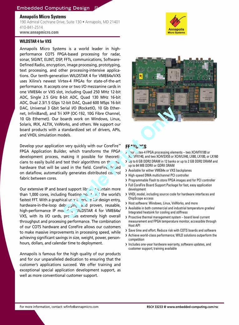
Embedded Computing Design Resource Guide Program
mab
le logicFPGAs
For more information, contact: [email protected]
Annapolis Micro Systems190 Admiral Cochrane Drive, Suite 130 • Annapolis, MD 21401 410-841-2514www.annapmicro.com
Annapolis Micro Systems is a world leader in high- performance COTS FPGA-based processing for radar, sonar, SIGINT, ELINT, DSP, FFTs, communications, Software-Defined Radio, encryption, image processing, prototyping, text processing, and other processing-intensive applica-tions. Our tenth-generation WILDSTAR 4 for VME64x/VXS uses Xilinx’s newest Virtex-4 FPGAs for state-of-the-art performance. It accepts one or two I/O mezzanine cards in one VME64x or VXS slot, including Quad 250 MHz 12-bit ADC, Single 2.5 GHz 8-bit ADC, Quad 130 MHz 16-bit ADC, Dual 2.3/1.5 GSps 12-bit DAC, Quad 600 MSps 16-bit DAC, Universal 3 Gbit Serial I/O (RocketIO, 10 Gb Ether-net, InfiniBand), and Tri XFP (OC-192, 10G Fibre Channel, 10 Gb Ethernet). Our boards work on Windows, Linux, Solaris, IRIX, ALTIX, VxWorks, and others. We support our board products with a standardized set of drivers, APIs, and VHDL simulation models.
Develop your application very quickly with our CoreFire™ FPGA Application Builder, which transforms the FPGA development process, making it possible for theoreti-cians to easily build and test their algorithms on the real hardware that will be used in the field. CoreFire, based on dataflow, automatically generates distributed control fabric between cores.
Our extensive IP and board support libraries contain more than 1,000 cores, including floating point and the world’s fastest FFT. With a graphical user interface for design entry, hardware-in-the-loop debugging, and proven, reusable, high-performance IP modules, WILDSTAR 4 for VME64x/VXS, with its I/O cards, provides extremely high overall throughput and processing performance. The combination of our COTS hardware and CoreFire allows our customers to make massive improvements in processing speed, while achieving significant savings in size, weight, power, person-hours, dollars, and calendar time to deployment.
Annapolis is famous for the high quality of our products and for our unparalleled dedication to ensuring that the customer’s applications succeed. We offer training and exceptional special application development support, as well as more conventional customer support.
WILDSTAR 4 for VXS
Four Virtex-4 FPGA processing elements – two XC4VFX100 or ›XC4VFX140, and two XC4VSX55 or XC4VLX40, LX80, LX100, or LX160Up to 6 GB DDR2 DRAM in 12 banks or up to 2 GB DDR2 DRAM and ›up to 64 MB DDRII or QDRII SRAMAvailable for either VME64x or VXS backplanes ›High-speed DMA multichannel PCI controller ›Programmable Flash to store FPGA images and for PCI controller ›Full CoreFire Board Support Package for fast, easy application ›developmentVHDL model, including source code for hardware interfaces and ›ChipScope accessHost software: Windows, Linux, VxWorks, and more ›Available in both commercial and industrial temperature grades/ ›Integrated heatsink for cooling and stiffnessProactive thermal management system – board level current ›measurement and FPGA temperature monitor, accessible through Host APISave time and effort. Reduce risk with COTS boards and software ›Achieve world-class performance; WILD solutions outperform the ›competitionIncludes one-year hardware warranty, software updates, and ›customer support; training available
FEATURES
RSC# 33233 @ www.embedded-computing.com/rsc
Embedded Computing Design Resource Guide March 2009 / 43
Single Prin
t Only
Single Prin
t Only
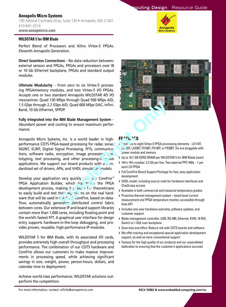
Embedded Computing Design Resource GuideP
rogr
amm
able
logi
cFPGAs
For more information, contact: [email protected]
Annapolis Micro Systems190 Admiral Cochrane Drive, Suite 130 • Annapolis, MD 21401 410-841-2514www.annapmicro.com
Perfect Blend of Processors and Xilinx Virtex-5 FPGAs. Eleventh Annapolis Generation.
Direct Seamless Connections – No data reduction between: external sensors and FPGAs, FPGAs and processors over IB or 10 Gb Ethernet backplane, FPGAs and standard output modules.
Ultimate Modularity – From zero to six Virtex-5 process-ing FPGA/memory modules, and two Virtex-5 I/O FPGAs. Accepts one or two standard Annapolis WILDSTAR 4/5 I/O mezzanines: Quad 130 MSps through Quad 500 MSps A/D, 1.5 GSps through 2.2 GSps A/D, Quad 600 MSps DAC, Infini-Band, 10 Gb Ethernet, SFPDP.
Fully Integrated into the IBM Blade Management System – Abundant power and cooling to ensure maximum perfor-mance. Annapolis Micro Systems, Inc. is a world leader in high-performance COTS FPGA-based processing for radar, sonar, SIGINT, ELINT, Digital Signal Processing, FFTs, communica-tions, software radio, encryption, image processing, pro-totyping, text processing, and other processing-intensive applications. We support our board products with a stan-dardized set of drivers, APIs, and VHDL simulation models.
Develop your application very quickly with our CoreFire™ FPGA Application Builder, which transforms the FPGA development process, making it possible for theoreticians to easily build and test their algorithms on the real hard-ware that will be used in the field. CoreFire, based on data-flow, automatically generates distributed control fabric between cores. Our extensive IP and board support libraries contain more than 1,000 cores, including floating point and the world’s fastest FFT. A graphical user interface for design entry supports hardware-in-the-loop debugging, and pro-vides proven, reusable, high-performance IP modules.
WILDSTAR 5 for IBM Blade, with its associated I/O cards, provides extremely high overall throughput and processing performance. The combination of our COTS hardware and CoreFire allows our customers to make massive improve-ments in processing speed, while achieving significant savings in size, weight, power, person-hours, dollars, and calendar time to deployment.
Achieve world-class performance; WILDSTAR solutions out- perform the competition.
WILDSTAR 5 for IBM Blade
From two to eight › Virtex-5 FPGA processing elements – LX110T, LX220T, LX330T, FX100T, FX130T, or FX200T. Six are pluggable with power module and memoryUp to 10.7 GB DDR2 DRAM per WILDSTAR 5 for › IBM Blade board144 x 144 crossbar. 3.2 Gb per line. Two external PPC 440s › – 1 per each I/O FPGAFull CoreFire Board Support Package for fast, easy application ›developmentVH › DL model, including source code for hardware interfaces and ChipScope accessAvailable in both commercial and industrial temperature grades ›
Pro › active thermal management system – board level current measurement and FPGA temperature monitor, accessible through Host APIIncludes one-year hardware warranty, software updates, and ›customer supportBla › de management controller. USB, RS-485, Ethernet, KVM, 16 RIO, Switch to 1 GbE over backplaneSave time and effort. Reduce risk with COTS boards and software ›
We offer training and exceptional special application development ›support, as well as more conventional supportFamous for the high quality of our products and our unparalleled ›dedication to ensuring that the customer’s applications succeed
FEATURES
RSC# 35882 @ www.embedded-computing.com/rsc
44 \ March 2009 Embedded Computing Design Resource Guide
Single Prin
t Only
Single Prin
t Only
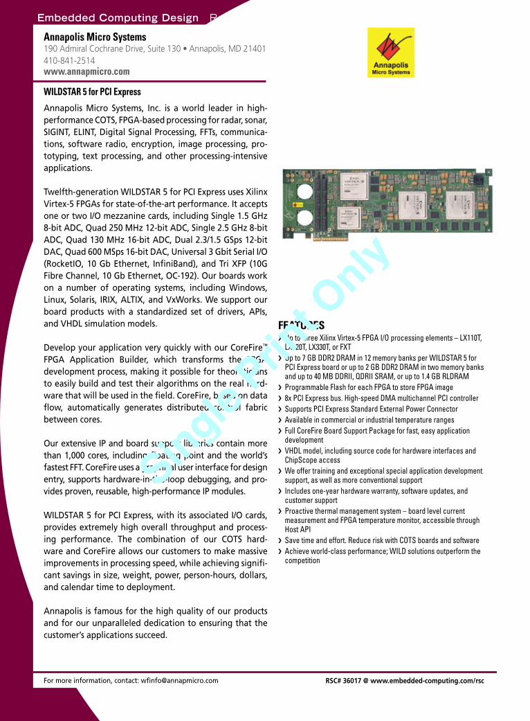
Embedded Computing Design Resource Guide Program
mab
le logicFPGAs
For more information, contact: [email protected]
Annapolis Micro Systems190 Admiral Cochrane Drive, Suite 130 • Annapolis, MD 21401 410-841-2514www.annapmicro.com
Annapolis Micro Systems, Inc. is a world leader in high- performance COTS, FPGA-based processing for radar, sonar, SIGINT, ELINT, Digital Signal Processing, FFTs, communica-tions, software radio, encryption, image processing, pro-totyping, text processing, and other processing-intensive applications.
Twelfth-generation WILDSTAR 5 for PCI Express uses Xilinx Virtex-5 FPGAs for state-of-the-art performance. It accepts one or two I/O mezzanine cards, including Single 1.5 GHz 8-bit ADC, Quad 250 MHz 12-bit ADC, Single 2.5 GHz 8-bit ADC, Quad 130 MHz 16-bit ADC, Dual 2.3/1.5 GSps 12-bit DAC, Quad 600 MSps 16-bit DAC, Universal 3 Gbit SeriaI I/O (RocketIO, 10 Gb Ethernet, InfiniBand), and Tri XFP (10G Fibre Channel, 10 Gb Ethernet, OC-192). Our boards work on a number of operating systems, including Windows, Linux, Solaris, IRIX, ALTIX, and VxWorks. We support our board products with a standardized set of drivers, APIs, and VHDL simulation models.
Develop your application very quickly with our CoreFire™ FPGA Application Builder, which transforms the FPGA development process, making it possible for theoreticians to easily build and test their algorithms on the real hard-ware that will be used in the field. CoreFire, based on data flow, automatically generates distributed control fabric between cores.
Our extensive IP and board support libraries contain more than 1,000 cores, including floating point and the world’s fastest FFT. CoreFire uses a graphical user interface for design entry, supports hardware-in-the-loop debugging, and pro-vides proven, reusable, high-performance IP modules.
WILDSTAR 5 for PCI Express, with its associated I/O cards, provides extremely high overall throughput and process-ing performance. The combination of our COTS hard-ware and CoreFire allows our customers to make massive improvements in processing speed, while achieving signifi-cant savings in size, weight, power, person-hours, dollars, and calendar time to deployment.
Annapolis is famous for the high quality of our products and for our unparalleled dedication to ensuring that the customer’s applications succeed.
WILDSTAR 5 for PCI Express
Up to three Xilinx Virtex-5 FPGA I/O processing elements – LX110T, ›LX220T, LX330T, or FXTUp to 7 GB DDR2 DRAM in 12 memory banks per WILDSTAR 5 for ›PCI Express board or up to 2 GB DDR2 DRAM in two memory banks and up to 40 MB DDRII, QDRII SRAM, or up to 1.4 GB RLDRAMProgrammable Flash for each FPGA to store FPGA image ›8x PCI Express bus. High-speed DMA multichannel PCI controller ›Supports PCI Express Standard External Power Connector ›Available in commercial or industrial temperature ranges ›Full CoreFire Board Support Package for fast, easy application ›developmentVHDL model, including source code for hardware interfaces and ›ChipScope accessWe offer training and exceptional special application development ›support, as well as more conventional supportIncludes one-year hardware warranty, software updates, and ›customer supportProactive thermal management system – board level current ›measurement and FPGA temperature monitor, accessible through Host APISave time and effort. Reduce risk with COTS boards and software ›Achieve world-class performance; WILD solutions outperform the ›competition
FEATURES
RSC# 36017 @ www.embedded-computing.com/rsc
Embedded Computing Design Resource Guide March 2009 / 45
Single Prin
t Only
Single Prin
t Only
Embedded Computing Design Resource Guide
Embedded Computing Design Resource GuideP
rogr
amm
able
logi
c
For more information, contact: [email protected] RSC# 32921 @ www.embedded-computing.com/rsc
Connect Tech Inc.42 Arrow Road • Guelph, ON, N1K 1S6 Canada519-836-1291 | 800-426-8979www.connecttech.com
Connect Tech’s reconfigurable FreeForm FPGA computing modules save valuable time and project dollars. Based on the Xilinx Virtex-5 and Spartan-3E FPGAs, FreeForm pro-vides a versatile platform for design flexibility.
FreeForm/PCI-104Virtex-5 FPGA, 5 million gates, 8MB Flash, 128MB DDR2- 400 memory, 64 single-ended or 32 LVDS I/O, RocketIO, 2x10/100 Ethernet, 2xRS-485, PowerPC option.
FreeForm/104Spartan-3E FPGA, 500,000 gates, 4MB Flash, standard/custom cores, counter/timers, digital I/O, Opto-22 compat-ibility, 5V power connector for stand-alone usage, LEDs, rotary switch, reset button.
FreeForm is perfect for real-time applications where speed and accuracy are critical.
FPGA & Digital I/O
Provides external 5V power connector for stand-alone operation ›Industrial temperature range models available (-40°C to +85°C) ›Free ISE WebPACK for complete FPGA design ›Reconfigurable in the field or through Connect Tech’s Engineering ›ServicesLifetime warranty and free technical support ›
FEATURES
FPGAs
Embedded Effi ciencyMaximum Performance at Minimum Consumption
CoreExpress® and the CoreExpress®-logo are registered trademarks of LiPPERT Embedded Computers.
Effi cient energy usage is a signifi cant com-petitive factor.
Utilizing highest integration levels, latest technologies, and the most powerful pro-cessors, for more than 25 years LIPPERT‘s embedded PCs marked the maximum pos-sible performance while maintaining mini-mum power dissipation.
LiPPERT - effi cient and rugged compo-nents, for market segments as diverse as automotive, automation, medical, military, and aerospace.
LiPPERT Embedded Computers Inc. 5555 Glenridge Connector, Suite 200 Atlanta, GA 30342Phone (404) 459 2870 · Fax (404) 459 [email protected] · www.lippertembedded.com
PCI/104-Express
Mini-ITX
PCI/104-ExpressPCI/104-Express
Mini-ITX
CoreExpress®
Board Formats for all Applications
LiP_Ad_USA_MES_178x124_090218.indd 1 19.02.2009 16:34:59 Uhr46 \ March 2009 Embedded Computing Design Resource Guide
Single Prin
t Only
Single Prin
t Only
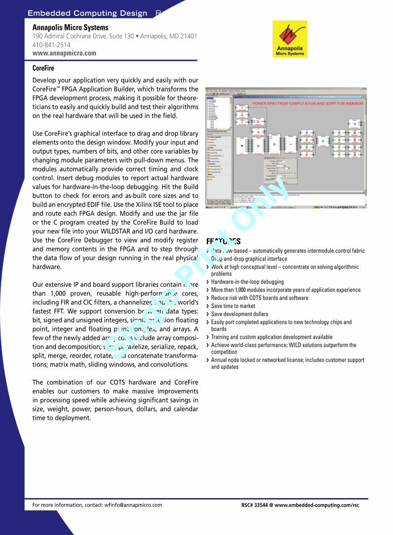
Embedded Computing Design Resource Guide Softw
areApplication platform
For more information, contact: [email protected]
Annapolis Micro Systems190 Admiral Cochrane Drive, Suite 130 • Annapolis, MD 21401 410-841-2514www.annapmicro.com
Develop your application very quickly and easily with our CoreFire™ FPGA Application Builder, which transforms the FPGA development process, making it possible for theore-ticians to easily and quickly build and test their algorithms on the real hardware that will be used in the field.
Use CoreFire’s graphical interface to drag and drop library elements onto the design window. Modify your input and output types, numbers of bits, and other core variables by changing module parameters with pull-down menus. The modules automatically provide correct timing and clock control. Insert debug modules to report actual hardware values for hardware-in-the-loop debugging. Hit the Build button to check for errors and as-built core sizes and to build an encrypted EDIF file. Use the Xilinx ISE tool to place and route each FPGA design. Modify and use the jar file or the C program created by the CoreFire Build to load your new file into your WILDSTAR and I/O card hardware. Use the CoreFire Debugger to view and modify register and memory contents in the FPGA and to step through the data flow of your design running in the real physical hardware.
Our extensive IP and board support libraries contain more than 1,000 proven, reusable high-performance cores, including FIR and CIC filters, a channelizer, and the world’s fastest FFT. We support conversion between data types: bit, signed and unsigned integers, single precision floating point, integer and floating point complex, and arrays. A few of the newly added array cores include array composi-tion and decomposition; slice, parallelize, serialize, repack, split, merge, reorder, rotate, and concatenate transforma-tions; matrix math, sliding windows, and convolutions.
The combination of our COTS hardware and CoreFire enables our customers to make massive improvements in processing speed while achieving significant savings in size, weight, power, person-hours, dollars, and calendar time to deployment.
CoreFire
Data flow-based – automatically generates intermodule control fabric ›Drag-and-drop graphical interface ›Work at high conceptual level – concentrate on solving algorithmic ›problemsHardware-in-the-loop debugging ›More than 1,000 modules incorporate years of application experience ›Reduce risk with COTS boards and software ›Save time to market ›Save development dollars ›Easily port completed applications to new technology chips and ›boardsTraining and custom application development available ›Achieve world-class performance; WILD solutions outperform the ›competitionAnnual node locked or networked license; includes customer support ›and updates
FEATURES
RSC# 33544 @ www.embedded-computing.com/rsc
Embedded Computing Design Resource Guide March 2009 / 47
Single Prin
t Only
Single Prin
t Only
Embedded Computing Design Resource Guide
Embedded Computing Design Resource GuideS
oftw
are
For more information, contact: [email protected] RSC# 40988 @ www.embedded-computing.com/rsc
Curtiss-Wright Controls Embedded Computing741-G Miller Drive, SE • Leesburg, VA 20175613-254-5112www.cwcembedded.com
Continuum Insights is a suite of GUI-based software tools designed to ease and optimize the development of appli-cation software for multi-computer embedded systems. Designed to support systems ranging from a few to hun-dreds of processors/cores, Continuum Insights enables application programmers greater visibility into the entire system through the collection of critical, periodic, non-intrusive, real-time data. Continuum Insights aims to pro-vide the level of information needed by developers of complex systems to accurately tune their system and ulti-mately speed time to market.
Continuum Insights harnesses the advantages of com-plementary Continuum products such as Continuum Firmware & BSP, Continuum Vector, and Continuum IPC. Continuum Insights is supported on Curtiss-Wright’s VPX/VPX-REDI based single board computers, and DSP and FPGA engines.
Continuum Insights
Quickly and easily visualize multi-computer system ›Hierarchical views of system provide status and health information ›at the system level down to the component levelEvent data collection across multiple processors and cores, ›correlated in time using a common time baseInitialize entire multi-computer or a group of processors with a ›set of executables (define, download, and launch) from a simple, configurable, user-defined launch planMulti-Node Debugger extends the capabilities of a source level ›debugger by supporting multiple nodes concurrently Set breakpoints across all processing nodes that when reached, will ›halt the entire system or a subset of the system
FEATURES
Diagnostic utilities
Naturally Air-cooled Fan-less Operation ▲ Operating Temperature 0º - 50ºC2G Vibration Resistance ▲ 10G Impact Resistance
BOX-PC 950 SeriesWorld’s Thinnest Dual Core Industrial PC
Designed for Digital Signage
Bootable Twin CF Slots
Optional Mounting Bracket VESA 100mm / 200mm compliant
True IDESupports Fixed-Disk CF1 for OS - 1 for storage
1”25mm
Fanless Dual Core Processor
High-performance Graphics
Built to Withstand Rugged Environments
Features Intel® Ultra Low Voltage Core Duo U2500
Provided by Intel® GMA950 Express Chipset
For more information: e-mail: [email protected]
Toll-free: 800-888-8884
CONTEC USA, Inc.1294 Lawrence Station Rd.Sunnyvale, CA 94089www.contecusa.com
RoHSCompliant
48 \ March 2009 Embedded Computing Design Resource Guide
Single Prin
t Only
Single Prin
t Only
Embedded Computing Design Resource Guide
Embedded Computing Design Resource Guide
For more information, contact: [email protected] RSC# 37420 @ www.embedded-computing.com/rsc
CodeSourcery9978 Granite Point Court • Granite Bay, CA 95746888-776-0262www.codesourcery.com
Sourcery G++™ professional C/C++ development tools from CodeSourcery offer high value at an affordable price. Sourcery G++ includes an IDE, compiler, debugger, simulator, and more tools for the embedded developer.
Sourcery G++ is available for the ARM®, ColdFire®, fido™, MIPS®, Power Architecture®, Stellaris®, and x86 processor architectures. Sourcery G++ runs on GNU/Linux® and Windows® host systems and targets bare metal, uClinux™, GNU/Linux and Windows systems.
Sourcery G++ Professional Edition features unlimited support from CodeSourcery’s expert engineers, and Sourcery G++ Personal Edition is designed for individuals and small development teams.
Download a free 30-day evaluation of the new spring 2009 release!
Sourcery G++
Eclipse › ™-based integrated development environmentOptimizing ISO-compliant GNU C/C++ compilers (GCC 4.3 plus ›enhancements)C/C++ runtime libraries ›Flexible GNU macroassembler and powerful GNU linker ›Source- and assembly-level GNU Debugger ›Debug Sprites for hardware debugging using a JTAG/BDM device ›Instruction set simulator and GNU/Linux application simulator based ›on QEMU™
Easy-to-use graphical installer and comprehensive documentation ›
FEATURES
IDE tools
Softw
are
For more information, contact: [email protected] RSC# 32775 @ www.embedded-computing.com/rsc
Altia, Inc.7222 Commerce Center Drive, Suite 240Colorado Springs, CO 80919719-598-4299www.altia.com
Altia DeepScreen is a graphics code generator that converts Altia Design prototype graphics into deployable graphics code. By simply selecting the design objects that represent the display portion of a product and clicking on the “Gen-erate Code” menu, ANSI C code is generated in seconds. This code can be generated for any RTOS that DeepScreen supports (Windows, Windows CE and .NET, UNIX, Linux, QNX, and more). DeepScreen will also generate code for a proprietary or limited RTOS and quickly integrate with an existing graphics library. Changes to interfaces can be accomplished quickly. Graphics code can be used on both high- and low-end targets – from Windows machines to FPGAs to 8-bit micros. DeepScreen saves programmers from the grunt work of graphics coding and allows devel-opers to meet aggressive schedules. DeepScreen supports 8-, 16-, and 32-bit processors with fixed point or floating point arithmetic.
Altia DeepScreen
Easily try different targets – dialog driven choice of target RTOS ›Choice of code generation optimizations ›Generates code for graphics, animation, stimulus, and control ›From Altia Design select items for code generation ›No limit to combination or number of objects that can be selected ›Link in your application code and use your own main loop ›Porting kit to generate code for currently unsupported OSs or GLs ›Supports 8-, 16-, and 32-bit processors ›Supports fixed point and floating point processors ›
FEATURES
IDE tools
Embedded Computing Design Resource Guide March 2009 / 49
Single Prin
t Only
Single Prin
t Only
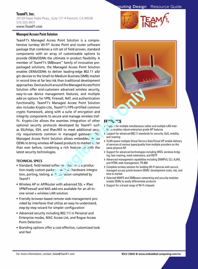
Embedded Computing Design Resource GuideNetworking
For more information, contact: [email protected]
TeamF1, Inc.39159 Paseo Padre Pkwy., Suite 121 • Fremont, CA 94538510-505-9931www.TeamF1.com
TeamF1’s Managed Access Point Solution is a compre-hensive turnkey Wi-Fi® Access Point and router software package that combines a rich set of field-proven, standard components with an array of customizable options to provide OEMs/ODMs the ultimate in product flexibility. A member of TeamF1’s SMBware™ family of innovative pre-packaged solutions, the Managed Access Point Solution enables OEMs/ODMs to deliver leading-edge 802.11 a/b/g/n devices to the Small-to-Medium Business (SMB) market in record time at far less risk than traditional development approaches. Devices built around the Managed Access Point Solution offer end-customers advanced wireless security, easy-to-use device management features, and multiple add-on options for VPN, Firewall, NAT, and authentication functionality. TeamF1’s Managed Access Point Solution also includes Krypto-Lite, TeamF1’s FIPS-certified common crypto framework, along with a suite of encryption and integrity components to secure and manage wireless traf-fic. Krypto-Lite allows the seamless integration of other optional security protocols developed by TeamF1 such as SSL/https, SSH, and IPsec/IKE to meet additional secu-rity requirements common in managed gateways. The Managed Access Point Solution allows embedded device OEMs to bring wireless AP-based products to market faster than ever before, combining a rich feature-set with the latest security technologies.
TECHNICAL SPECSStandard, field-tested software solution in a produc-•tion-ready custom package, with all hardware integra-tion, porting, testing, and validation completed by TeamF1
Wireless AP or AP/Router with advanced SSL + IPsec •VPN/Firewall and NAS add-ons available for an all-in-one wired + wireless LAN solution
Friendly browser-based remote web-management pro-•vided by interfaces that utilize an easy-to-understand, step-by-step wizard for simpler configuration
Advanced security including 802.11i in Personal and •Enterprise modes, MAC Access List, and Rogue Access Point Detection
Branding options offer a cost-effective, customized look •and feel
Managed Access Point Solution
Support for multiple simultaneous radios and multiple LAN inter- ›faces enables robust enterprise-grade AP featuresSupport for advanced 802.11 standards for security, QoS, mobility, ›and roamingVLAN aware multiple Virtual Service Sets/Virtual AP enable delivery ›of services of various types/quality from multiple providers on the same physical APSupport for advanced technologies including WDS, wireless bridg- ›ing, fast-roaming, mesh extensions, and RSTPAdvanced management capabilities including SNMPv3, CLI, AJAX, ›and HTML web-management, TR-069Complete turnkey solution for building Wi-Fi devices with secure, ›managed access points lessens OEMs’ development costs, risk, and time to marketSelected MAPS and SMBware networking and security modules ›enable OEMs to easily differentiate productsSupport for a broad range of Wi-Fi chipsets ›
FEATURES
RSC# 33643 @ www.embedded-computing.com/rsc
Sof
twar
e
50 \ March 2009 Embedded Computing Design Resource Guide
Single Prin
t Only
Single Prin
t Only
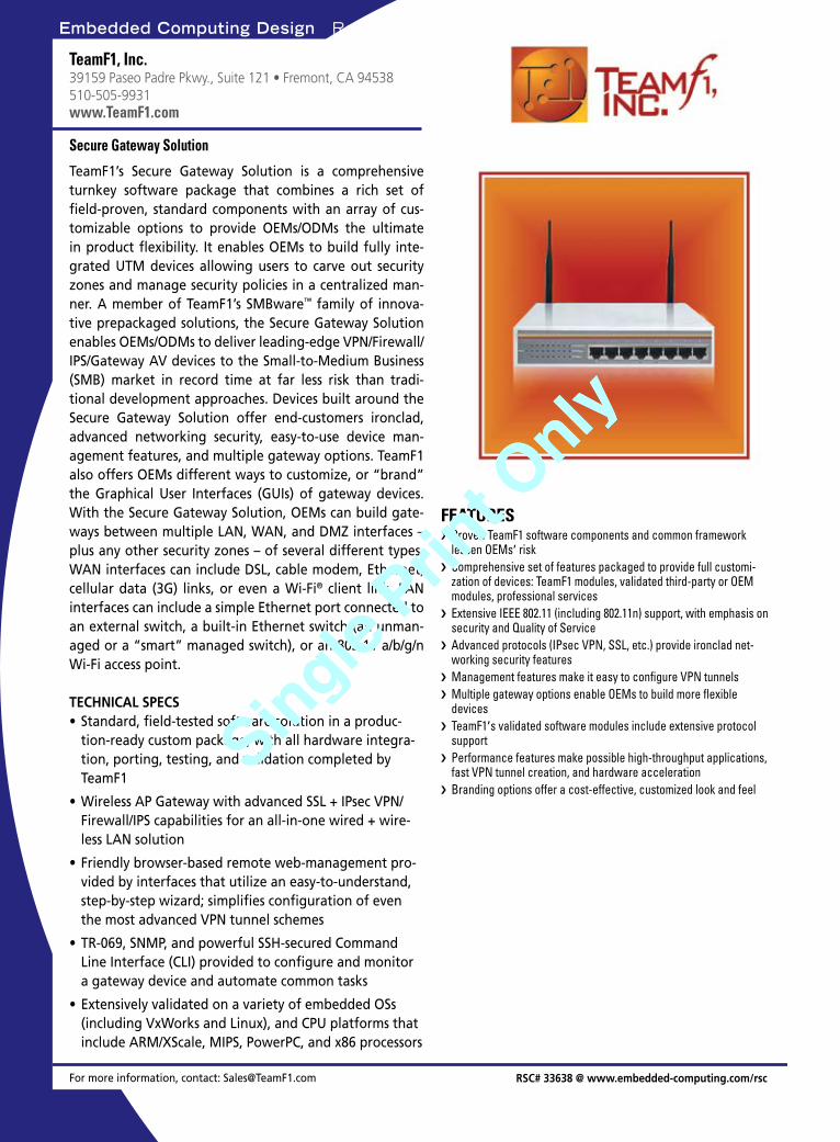
Embedded Computing Design Resource Guide Networking
For more information, contact: [email protected]
TeamF1, Inc.39159 Paseo Padre Pkwy., Suite 121 • Fremont, CA 94538510-505-9931www.TeamF1.com
TeamF1’s Secure Gateway Solution is a comprehensive turnkey software package that combines a rich set of field-proven, standard components with an array of cus-tomizable options to provide OEMs/ODMs the ultimate in product flexibility. It enables OEMs to build fully inte-grated UTM devices allowing users to carve out security zones and manage security policies in a centralized man-ner. A member of TeamF1’s SMBware™ family of innova-tive prepackaged solutions, the Secure Gateway Solution enables OEMs/ODMs to deliver leading-edge VPN/Firewall/IPS/Gateway AV devices to the Small-to-Medium Business (SMB) market in record time at far less risk than tradi-tional development approaches. Devices built around the Secure Gateway Solution offer end-customers ironclad, advanced networking security, easy-to-use device man-agement features, and multiple gateway options. TeamF1 also offers OEMs different ways to customize, or “brand” the Graphical User Interfaces (GUIs) of gateway devices. With the Secure Gateway Solution, OEMs can build gate-ways between multiple LAN, WAN, and DMZ interfaces – plus any other security zones – of several different types. WAN interfaces can include DSL, cable modem, Ethernet, cellular data (3G) links, or even a Wi-Fi® client link. LAN interfaces can include a simple Ethernet port connected to an external switch, a built-in Ethernet switch (an unman-aged or a “smart” managed switch), or an 802.11 a/b/g/n Wi-Fi access point.
TECHNICAL SPECSStandard, field-tested software solution in a produc-•tion-ready custom package, with all hardware integra-tion, porting, testing, and validation completed by TeamF1
Wireless AP Gateway with advanced SSL + IPsec VPN/•Firewall/IPS capabilities for an all-in-one wired + wire-less LAN solution
Friendly browser-based remote web-management pro-•vided by interfaces that utilize an easy-to-understand, step-by-step wizard; simplifies configuration of even the most advanced VPN tunnel schemes
TR-069, SNMP, and powerful SSH-secured Command •Line Interface (CLI) provided to configure and monitor a gateway device and automate common tasks
Extensively validated on a variety of embedded OSs •(including VxWorks and Linux), and CPU platforms that include ARM/XScale, MIPS, PowerPC, and x86 processors
Secure Gateway Solution
Proven TeamF1 software components and common framework ›lessen OEMs’ riskComprehensive set of features packaged to provide full customi- ›zation of devices: TeamF1 modules, validated third-party or OEM modules, professional servicesExtensive IEEE 802.11 (including 802.11n) support, with emphasis on ›security and Quality of ServiceAdvanced protocols (IPsec VPN, SSL, etc.) provide ironclad net- ›working security featuresManagement features make it easy to configure VPN tunnels ›Multiple gateway options enable OEMs to build more flexible ›devicesTeamF1 › ’s validated software modules include extensive protocol supportPerformance features make possible high-throughput applications, ›fast VPN tunnel creation, and hardware accelerationBranding options offer a cost-effective, customized look and feel ›
FEATURES
RSC# 33638 @ www.embedded-computing.com/rsc
Softw
are
Embedded Computing Design Resource Guide March 2009 / 51
Single Prin
t Only
Single Prin
t Only
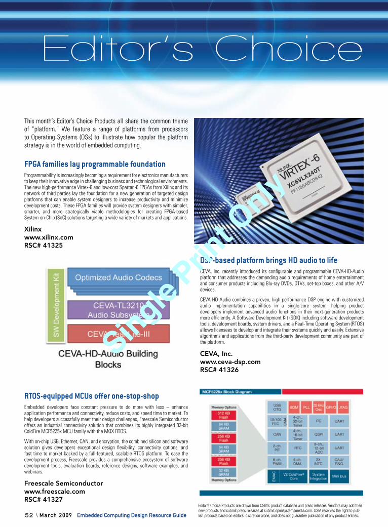
Editor’s Choice Embedded Computing Design Resource Guide
52 \ March 2009 Embedded Computing Design Resource Guide
This month’s Editor’s Choice Products all share the common theme of “platform.” We feature a range of platforms from processors to Operating Systems (OSs) to illustrate how popular the platform strategy is in the world of embedded computing.
FPGA families lay programmable foundationProgrammability is increasingly becoming a requirement for electronics manufacturers to keep their innovative edge in challenging business and technological environments. The new high-performance Virtex-6 and low-cost Spartan-6 FPGAs from Xilinx and its network of third parties lay the foundation for a new generation of targeted design platforms that can enable system designers to increase productivity and minimize development costs. These FPGA families will provide system designers with simpler, smarter, and more strategically viable methodologies for creating FPGA-based System-on-Chip (SoC) solutions targeting a wide variety of markets and applications.
Xilinxwww.xilinx.comRSC# 41325
DSP-based platform brings HD audio to lifeCEVA, Inc. recently introduced its configurable and programmable CEVA-HD-Audio platform that addresses the demanding audio requirements of home entertainment and consumer products including Blu-ray DVDs, DTVs, set-top boxes, and other A/V devices.
CEVA-HD-Audio combines a proven, high-performance DSP engine with customized audio implementation capabilities in a single-core system, helping product developers implement advanced audio functions in their next-generation products more efficiently. A Software Development Kit (SDK) including software development tools, development boards, system drivers, and a Real-Time Operating System (RTOS) allows licensees to develop and integrate their systems quickly and easily. Extensive algorithms and applications from the third-party development community are part of the platform.
CEVA, Inc.www.ceva-dsp.comRSC# 41326
RTOS-equipped MCUs offer one-stop-shopEmbedded developers face constant pressure to do more with less – enhance application performance and connectivity, reduce costs, and speed time to market. To help developers successfully meet their design challenges, Freescale Semiconductor offers an industrial connectivity solution that combines its highly integrated 32-bit ColdFire MCF5225x MCU family with the MQX RTOS.
With on-chip USB, Ethernet, CAN, and encryption, the combined silicon and software solution gives developers exceptional design flexibility, connectivity options, and fast time to market backed by a full-featured, scalable RTOS platform. To ease the development process, Freescale provides a comprehensive ecosystem of software development tools, evaluation boards, reference designs, software examples, and webinars.
Freescale Semiconductorwww.freescale.comRSC# 41327
Editor’s Choice
Editor’s Choice Products are drawn from OSM’s product database and press releases. Vendors may add their new products and submit press releases at submit.opensystemsmedia.com. OSM reserves the right to pub-lish products based on editors’ discretion alone, and does not guarantee publication of any product entries.
Single Prin
t Only
Single Prin
t Only
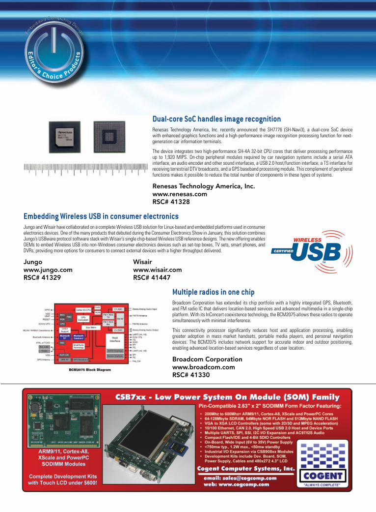
Dual-core SoC handles image recognitionRenesas Technology America, Inc. recently announced the SH7776 (SH-Navi3), a dual-core SoC device with enhanced graphics functions and a high-performance image recognition processing function for next-generation car information terminals.
The device integrates two high-performance SH-4A 32-bit CPU cores that deliver processing performance up to 1,920 MIPS. On-chip peripheral modules required by car navigation systems include a serial ATA interface, an audio encoder and other sound interfaces, a USB 2.0 host/function interface, a TS interface for receiving terrestrial DTV broadcasts, and a GPS baseband processing module. This complement of peripheral functions makes it possible to reduce the total number of components in these types of systems.
Renesas Technology America, Inc.www.renesas.comRSC# 41328
Embedding Wireless USB in consumer electronicsJungo and Wisair have collaborated on a complete Wireless USB solution for Linux-based and embedded platforms used in consumer electronics devices. One of the many products that debuted during the Consumer Electronics Show in January, this solution combines Jungo’s USBware protocol software stack with Wisair’s single chip-based Wireless USB reference designs. The new offering enables OEMs to embed Wireless USB into non-Windows consumer electronics devices such as set-top boxes, TV sets, smart phones, and DVRs, providing more options for consumers to connect external devices with a higher throughput delivered.
Jungo Wisairwww.jungo.com www.wisair.comRSC# 41329 RSC# 41447
Multiple radios in one chipBroadcom Corporation has extended its chip portfolio with a highly integrated GPS, Bluetooth, and FM radio IC that delivers location-based services and advanced multimedia in a single-chip platform. With its InConcert coexistence technology, the BCM2075 allows these radios to operate simultaneously with minimal interference.
This connectivity processor significantly reduces host and application processing, enabling greater adoption in mass market handsets, portable media players, and personal navigation devices. The BCM2075 includes network support for accurate indoor and outdoor positioning, enabling advanced location-based services regardless of user location.
Broadcom Corporationwww.broadcom.comRSC# 41330
Editor’s Choice
PROFILE INDEXAdvertiser Category Page Altia, Inc. Software 49Annapolis Micro Systems Programmable logic 40Annapolis Micro Systems Programmable logic 41Annapolis Micro Systems Programmable logic 42Annapolis Micro Systems Programmable logic 43Annapolis Micro Systems Programmable logic 44Annapolis Micro Systems Programmable logic 45Annapolis Micro Systems Software 47CodeSourcery Software 49Connect Tech Inc. Programmable logic 46Curtiss-Wright Controls Software 48Fidus Systems Inc. Design aids 34Highland Technology, Inc. Interfaces 35Octasic Inc. Microcontrollers and processors 36Radian Heatsinks Design aids 34TeamF1, Inc. Software 50TeamF1, Inc. Software 51Texas Instruments Microcontrollers and processors 37Tri-M Engineering Microcontrollers and processors 38Tri-M Engineering Power management 39Tundra Semiconductor Interfaces 35
Access io Ad here
Page # Advertiser Ad title 54 ACCES I/O Products, Inc. USB embedded I/O solutions 31 ACT/Technico Solid state storage solutions 13 Aitech Defense Systems On land or in the air 38 American Portwell Technology Your trusted provider 5 Annapolis Micro Systems, Inc. WILDSTAR 5 53 Cogent Computer Systems, Inc. CSB7xx 18 Concurrent Technologies, Inc. x86 processor boards 48 Contec USA BOX-PC 950 Series 55 Embedded Systems Conference We speak embedded 6 Interface Concept Switches & IP routers 56 Jacyl Technology Inc. XG-5000K 46 LiPPERT Embedded Computers Embedded efficiency 23 MEN Micro Elektronik GmbH ESMexpress COM: Rugged PowerPC 27 Micro Digital, Inc. Looking for the right software 1 Moxa Technologies, Inc. Empower your competitiveness 33 North Atlantic Industries MIL-STD is the only thing 11 Performance Technologies Our advanced managed platforms 39 Precision Analog Systems (PAS) Your source for VMEbus & PCI Express 17 Swissbit Experience the value 15 Technobox, Inc. Create your own PMCs 19 Technologic Systems 7" touch panel computer 48 TEWS Technologies LLC COTS I/O solutions 25 Tri-M Systems Inc. PC/104 Can-Tainer 29 Tri-M Systems Inc. 100MHz PC/104 module 9 Vector Electronics & Technology, Inc. VME and cPCI system packaging 7 VersaLogic Corporation You design products 2,3 WinSystems, Inc. A 1GHz fanless industrial SBC
Advertiser Information
Embedded knowledge in motion
video.opensystemsmedia.com

Learn today. Design tomorrow.
ESC_Speaker_ad 012009 outlines.indd 1 1/20/09 1:36:15 PM
54 ACCES I/O Products, Inc. USB embedded I/O solutions 31 ACT/Technico Solid state storage solutions 13 Aitech Defense Systems On land or in the air 38 American Portwell Technology Your trusted provider 5 Annapolis Micro Systems, Inc. WILDSTAR 5 53 Cogent Computer Systems, Inc. CSB7xx 18 Concurrent Technologies, Inc. x86 processor boards 48 Contec USA BOX-PC 950 Series 55 Embedded Systems Conference We speak embedded 6 Interface Concept Switches & IP routers 56 Jacyl Technology Inc. XG-5000K 46 LiPPERT Embedded Computers Embedded efficiency 23 MEN Micro Elektronik GmbH ESMexpress COM: Rugged PowerPC 27 Micro Digital, Inc. Looking for the right software 1 Moxa Technologies, Inc. Empower your competitiveness 33 North Atlantic Industries MIL-STD is the only thing 11 Performance Technologies Our advanced managed platforms 39 Precision Analog Systems (PAS) Your source for VMEbus & PCI Express 17 Swissbit Experience the value 15 Technobox, Inc. Create your own PMCs 19 Technologic Systems 7" touch panel computer 48 TEWS Technologies LLC COTS I/O solutions 25 Tri-M Systems Inc. PC/104 Can-Tainer 29 Tri-M Systems Inc. 100MHz PC/104 module 9 Vector Electronics & Technology, Inc. VME and cPCI system packaging 7 VersaLogic Corporation You design products 2,3 WinSystems, Inc. A 1GHz fanless industrial SBC
Advertiser Information
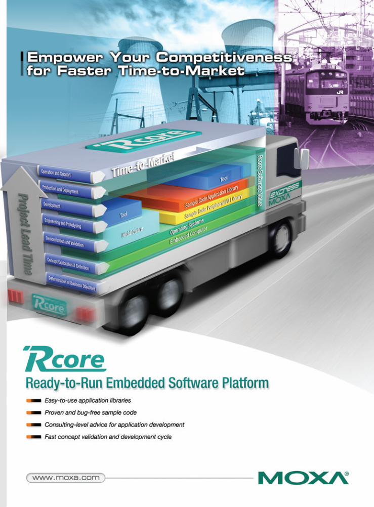
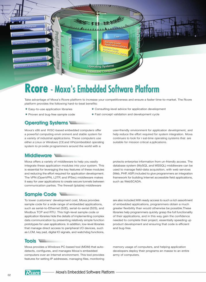
Moxa's x86 and RISC-based embedded computers offer a powerful computing envir onment and stable system for a variety of industrial applica tions. These computers use either a Linux or Windows (CEand XPe)embedded operatingsystem to provide programmers around the world with a
user-friendly environment for application development, andhelp reduce the effort required for system integration. Moxacontinues to look for r eal-time operating systems that are suitable for mission critical a pplications.
Easy-to-use application libraries
Proven and bug-free sample code
Take advantage of Moxa's Rcore platform to increase your competitiveness and ensure a faster time-to-market. The Rcore platform provides the following hard-to-beat bene�ts:
Consulting-level advice for application development
Fast concept validation and development cycle
Moxa offers a variety of middleware to help you easily integrate these application modules into your system. This is essential for leveraging the key features of these modulesand reducing the effort required for application development.The VPN (OpenVPN, L2TP, and IPSec) middleware makes it easy for user applications to create secure tunnels betweencommunication parties. The �rewall (iptable) middleware
protects enterprise information from un-friendly access. Thedatabase system (MySQL and MSSQL) middleware can beused to manage �eld-data acquisition, with web services (Web, PHP, ASP) included to give programmers an integrationframework for building Internet accessible �eld applications,such as WebSCADA.
To lower customers' development cost, Moxa provides sample code for a wide range of embedded applications, such as serial-to-Ethernet (S2E), serial-to-serial (S2S), and Modbus TCP and RTU. This high-level sample code or application libraries hide the details of implementing complexdata communication by presenting relatively simple functionprototypes for user applications. In addition, low-level librariesthat manage direct access to peripheral I/O devices, such as LCM, key pad, digital IO signals, and watchdog functions,
are also included.With ready access to such a rich assortmentof embedded applications, programmers obtain a much greater �exibility than would otherwise be possible.These libraries help programmers quickly grasp the full functionalityof their applications, and in this way gain the con�dence needed to complete their project, essentially speeding up product development and ensuring that code is ef�cient and bug-free.
Moxa provides a Windows PC-based tool (MDM) that auto-detects, con�gures, and manages Moxa's embeddedcomputers over an Internet environment. This tool providesfeatures for setting IP addresses, managing �les, monitoring
memory usage of computers, and helping application developers deploy their programs en masse to an entire army of computers.
02
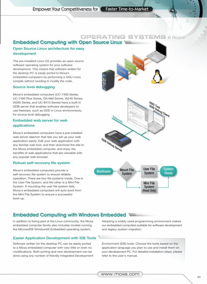
Open Source Linux architecture for easy development
The pre-installed Linux OS provides an open source software operating system for your software development. This means that software written for the desktop PC is easily ported to Moxa's embedded computers by performing a GNU cross compile without needing to modify the code.
Source level debugging
Moxa's embedded computers (UC-7400 Series, UC-7400 Plus Series, DA-660 Series, IA240 Series, IA260 Series, and UC-8410 Series) have a built-in GDB server that enables software developers to use freeware, such as DDD in Linux environments, for source level debugging.
Embedded web server for web applications
Moxa's embedded computers have a pre-installed web server daemon that lets you set up your web application easily. Edit your web application with any familiar web tool, and then download the site to the Moxa embedded computer, and enjoy the bene�ts of web applications that are viewable with any popular web browser.
Robust self-recovery file system
Moxa's embedded computers provide a self-recovery �le system to ensure reliable operation. There are two �le systems inside. One is the User File System, and the other is a Mini File System. If mounting the user �le system fails, Moxa's embedded computers will auto-boot from the Mini File System to ensure a successful boot-up.
In addition to being part of the Linux community, the Moxaembedded computer family also includes models running the Microsoft® Windows® Embedded operating system.
Adopting a widely used programming environment makes our embedded computers suitable for software developmentand legacy system migration.
Easier Application Development with IDE Tools
Software written for the desktop PC can be easily ported to a Moxa embedded computer with very little or even no modi�cations. Both porting and new development can be done using any number of friendly Integrated Development
Environment (IDE) tools. Choose the tools based on the application language you plan to use and install them on your development PC. For detailed installation steps, pleaserefer to the user's manual.
03
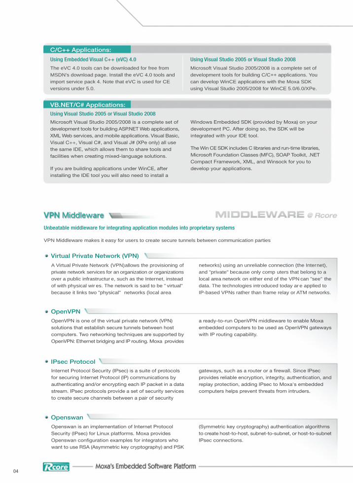
C/C++ Applications:
Using Embedded Visual C++ (eVC) 4.0
The eVC 4.0 tools can be downloaded for free from MSDN's download page. Install the eVC 4.0 tools and import service pack 4. Note that eVC is used for CE versions under 5.0.
Using Visual Studio 2005 or Visual Studio 2008
Microsoft Visual Studio 2005/2008 is a complete set of development tools for building C/C++ applications. You can develop WinCE applications with the Moxa SDK using Visual Studio 2005/2008 for WinCE 5.0/6.0/XPe.
VB.NET/C# Applications:Using Visual Studio 2005 or Visual Studio 2008
Microsoft Visual Studio 2005/2008 is a complete set of development tools for building ASP.NET Web applications,XML Web services, and mobile applications. Visual Basic,Visual C++, Visual C#, and Visual J# (XPe only) all use the same IDE, which allows them to share tools and facilities when creating mixed-language solutions.
If you are building applications under WinCE, after installing the IDE tool you will also need to install a
Windows Embedded SDK (provided by Moxa) on your development PC. After doing so, the SDK will be integrated with your IDE tool.
The Win CE SDK includes C libraries and run-time libraries,Microsoft Foundation Classes (MFC), SOAP Toolkit, .NETCompact Framework, XML, and Winsock for you to develop your applications.
04
Unbeatable middleware for integrating application modules into proprietary systems
VPN Middleware makes it easy for users to create secure tunnels between communication parties
OpenVPN
OpenVPN is one of the virtual private network (VPN) solutions that establish secure tunnels between host computers. Two networking techniques are supported byOpenVPN: Ethernet bridging and IP routing. Moxa provides
a ready-to-run OpenVPN middleware to enable Moxa embedded computers to be used as OpenVPN gatewayswith IP routing capability.
Virtual Private Network (VPN)
A Virtual Private Network (VPN)allows the provisioning ofprivate network services for an organization or organizationsover a public infrastructur e, such as the Internet, instead of with physical wir es. The network is said to be " virtual" because it links two "physical" networks (local area
networks) using an unreliable connection (the Internet), and "private" because only comp uters that belong to a local area network on either end of the VPN can "see" thedata. The technologies introduced today ar e applied to IP-based VPNs rather than frame relay or ATM networks.
Openswan
Openswan is an implementation of Internet Protocol Security (IPsec) for Linux platforms. Moxa provides Openswan con�guration examples for integrators who want to use RSA (Asymmetric key cryptography) and PSK
(Symmetric key cryptography) authentication algorithms to create host-to-host, subnet-to-subnet, or host-to-subnetIPsec connections.
IPsec ProtocolInternet Protocol Security (IPsec) is a suite of protocols for securing Internet Protocol (IP) communications by authenticating and/or encrypting each IP packet in a datastream. IPsec protocols provide a set of security servicesto create secure channels between a pair of security
gateways, such as a router or a �rewall. Since IPsec provides reliable encryption, integrity, authentication, andreplay protection, adding IPsec to Moxa's embedded computers helps prevent threats from intruders.
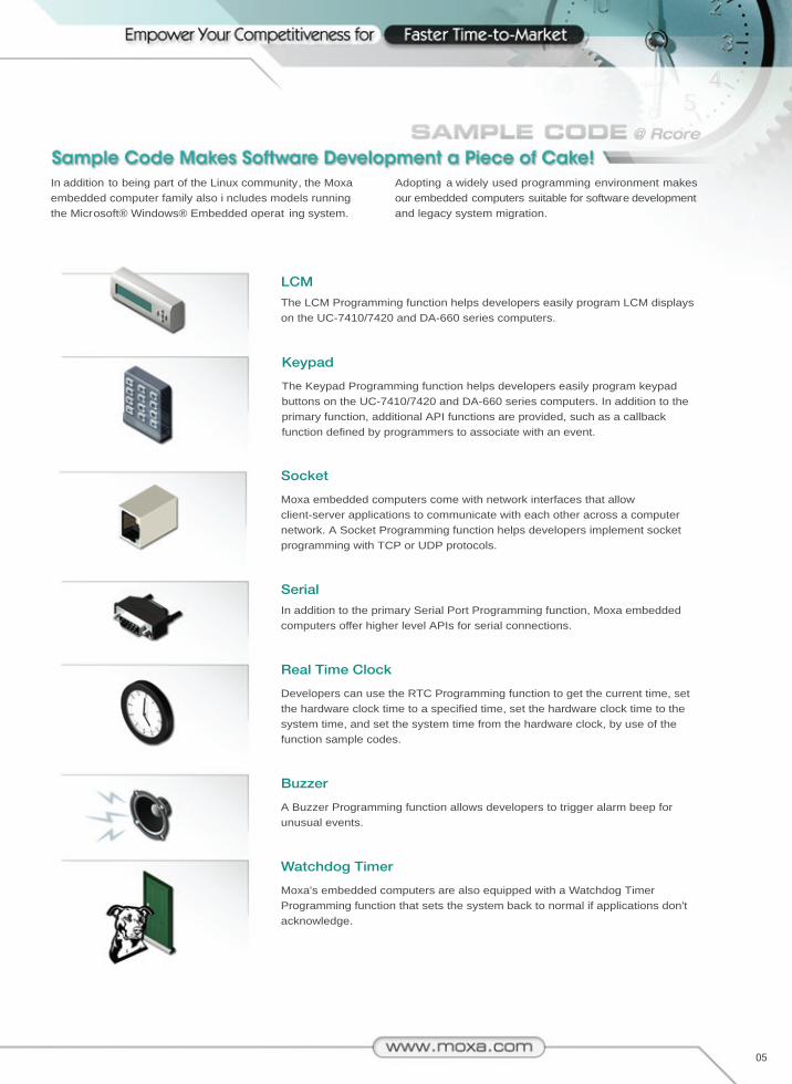
05
In addition to being part of the Linux community, the Moxaembedded computer family also i ncludes models running the Microsoft® Windows® Embedded operat ing system.
Adopting a widely used programming environment makesour embedded computers suitable for software developmentand legacy system migration.
The LCM Programming function helps developers easily program LCM displays on the UC-7410/7420 and DA-660 series computers.
LCM
The Keypad Programming function helps developers easily program keypad buttons on the UC-7410/7420 and DA-660 series computers. In addition to the primary function, additional API functions are provided, such as a callback function defined by programmers to associate with an event.
Keypad
Moxa embedded computers come with network interfaces that allow client-server applications to communicate with each other across a computer network. A Socket Programming function helps developers implement socket programming with TCP or UDP protocols.
Socket
In addition to the primary Serial Port Programming function, Moxa embedded computers offer higher level APIs for serial connections.
Serial
Developers can use the RTC Programming function to get the current time, set the hardware clock time to a specified time, set the hardware clock time to the system time, and set the system time from the hardware clock, by use of the function sample codes.
Real Time Clock
A Buzzer Programming function allows developers to trigger alarm beep for unusual events.
Buzzer
Moxa's embedded computers are also equipped with a Watchdog Timer Programming function that sets the system back to normal if applications don't acknowledge.
Watchdog Timer
Systems that incorporate several devices located at remotesites present a big challenge to soluti on providers. This is particularly true for industria l applications that use severalheadless embedded computers distributed over a wide area.
Although this type of computer is generally accessible fromover the network, the existing remote management optionspresent a rather clumsy solution for managing large numbersof embedded computers.
Perhaps the most common method of managing embeddedcomputers remotely over the network is to use Telnet/SSH.However, one of the main drawbacks to this type of management is that you can only connect to one embeddedcomputer at a time. In addition, the administrator must
actively type in the IP address of the embedded computer to establish the Telnet/SSH connection. It can be a real nightmare to keep track of which IP address is associated with which embedded computer.
Another method of managing an embedded computer includes working from the command line. Although this canbe done from over the network, most administrators �nd it dif�cult to remember all of the commands that are requiredto manage �les and run programs. Script �les that combine
several commands in one text �le can be used to automatethe command line method, but this option can also be quitetime-consuming for administrators that manage tens if not hundreds of machines.
06
Moxa Device Manager (MDM for short) is an easy-to-use remote management tool for managing Moxa's ready-to-run embedded computers over the Internet. Moxa's embedded computers make excellent front-end computersat remote sites for on-site data collection and industrial control applications. MDM is designed to make it easy for
system administrators to manage their remote embedded computers. One of the key benefits of MDM is that management tasks, such as con�guring the network, managing and/or transmitting text and binary �les, and monitoring and controlling processes, can be handled easilyusing a Windows-based user interface. In addition, MDM
07
Remote Control and Management
Supports all models of Moxa's embedded computers and Linux, WinCE, WinXPe operating systems
Control and monitor remote embedded units over the Internet
Broadcast search for Moxa embedded computers on the same LAN
Get instant device status
List basic information (IP, Model, Firmware version, OS, hostname, CPU, product image, memory information, and storage information) of all devices on the main page
Easy Installation and Setup
An MDM Agent program running on an embedded computer can be started automatically at boot-up
MDM Tool and Gateway can be installed on any PC running Windows XP
Command-line Free Configuration and Maintenance
Launch programs automatically when booting up
One-to-multiple �le transfers
Perform remote �le system management
Con�gure network interfaces
Monitor and kill processes
View detailed system information
Reboot devices
Upgrade �rmware for multiple devices at one time
Update system time
Easy-to-use User Interface
User-friendly "click and operate" interface for remote device management
Friendly windows-based utilities for easy configuration
Moxa Device Manager comes with MDM Agent, MDM Tool,and MDM Gateway. Users can download the Moxa Device
Manager package from the "Support --> Softwar e" page on Moxa's website.
can be used to manage dif ferent models of embedded computers, and embedded compute rs that use different operating systems, all from one centrally located computer.As long as the individual embedded computers ar e pre-installed with an MDM agent, th ey can be recognized and managed by the unified MDM tool from your PC. These features help ensure that MDM gives system integrators anefficient tool for handling all r emote devices from one computer.
In addition to controlling heterogeneous computer systems,the traffic between the MDM tool and any of the MDM agentsis encrypted. This feature protects data transmitted fr om the system. Users can comfortab ly manage the remote devices without worrying about the usual risks associated with transmitting data over a n etwork.
Web-based Management SystemMoxa's embedded computers are network-centric programmable platforms designed to be used as front-end computers for data acquisition and industrial control. The embedded computer is often located away from the system administrator in the same harsh environment as the controlled devices. This makes the task of managing the computer remotely an important aspect of the embedded computer's operation.
To resolve this remote management issue and reduce the work load of the system administrator, the Moxa embedded computer is installed with a Web-based management system. The system incorporates often-used features into an internal site and categorizes the features on a menu bar, as shown in the accompanying figures.
System Information
Networking/Server Configuration
Process (Thread) Monitoring/Control
Services Monitoring/Control
Binary/Text File Management and Upload
This web-based management system allows you to manage web sites, the registry database for system and application programs, and many other aspects of the computer's operation.
©2009 Moxa Inc., all rights reserved.The Moxa logo is a registered trademark of Moxa Inc.All other logos appearing in this catalog are the intellectual property of the respective company, product, or organization associated with the logo.
Become a member and get more details at:
P/N: 1900030901010
Toll-free: 1-888-MOXA-USA (1-888-669-2872)Tel: +1-714-528-6777Fax: [email protected]
Shanghai OfficeTel: +86-21-5258-9955Fax: [email protected]
Beijing OfficeTel: +86-10-6872-3959/60/61Fax: [email protected]
Shenzhen OfficeTel: +86-755-8368-4084/94Fax: [email protected]
Tel: +49-89-3 70 03 99-0Fax: +49-89-3 70 03 [email protected]
Tel: +886-2-8919-1230Fax: [email protected]