Embed Size (px)
Citation preview
Industrial Robot: An International JournalEmerald Article: High-level programming and control for industrial robotics: using a hand-held accelerometer-based input device for gesture and posture recognitionPedro Neto, J. Norberto Pires, A. Paulo Moreira
Article information:
To cite this document: Pedro Neto, J. Norberto Pires, A. Paulo Moreira, (2010),"High-level programming and control for industrial robotics: using a hand-held accelerometer-based input device for gesture and posture recognition", Industrial Robot: An International Journal, Vol. 37 Iss: 2 pp. 137 - 147
Permanent link to this document: http://dx.doi.org/10.1108/01439911011018911
Downloaded on: 10-04-2012
References: This document contains references to 28 other documents
To copy this document: [email protected]
This document has been downloaded 537 times.
Access to this document was granted through an Emerald subscription provided by Emerald Author Access
For Authors: If you would like to write for this, or any other Emerald publication, then please use our Emerald for Authors service. Information about how to choose which publication to write for and submission guidelines are available for all. Additional help for authors is available for Emerald subscribers. Please visit www.emeraldinsight.com/authors for more information.
About Emerald www.emeraldinsight.comWith over forty years' experience, Emerald Group Publishing is a leading independent publisher of global research with impact in business, society, public policy and education. In total, Emerald publishes over 275 journals and more than 130 book series, as well as an extensive range of online products and services. Emerald is both COUNTER 3 and TRANSFER compliant. The organization is a partner of the Committee on Publication Ethics (COPE) and also works with Portico and the LOCKSS initiative for digital archive preservation.
*Related content and download information correct at time of download.
Research article
High-level programming and control for industrialrobotics: using a hand-held accelerometer-basedinput device for gesture and posture recognition
Pedro Neto and J. Norberto Pires
Department of Mechanical Engineering – Polo II, University of Coimbra, Coimbra, Portugal, and
A. Paulo MoreiraINESC Porto – Institute for Systems and Computer Engineering of Porto, Porto, Portugal and
Department of Electrical and Computer Engineering, University of Porto, Porto, Portugal
AbstractPurpose – Most industrial robots are still programmed using the typical teaching process, through the use of the robot teach pendant. This isa tedious and time-consuming task that requires some technical expertise, and hence new approaches to robot programming are required.The purpose of this paper is to present a robotic system that allows users to instruct and program a robot with a high-level of abstraction from the robotlanguage.Design/methodology/approach – The paper presents in detail a robotic system that allows users, especially non-expert programmers, to instruct andprogram a robot just showing it what it should do, in an intuitive way. This is done using the two most natural human interfaces (gestures and speech),a force control system and several code generation techniques. Special attention will be given to the recognition of gestures, where the data extractedfrom a motion sensor (three-axis accelerometer) embedded in the Wii remote controller was used to capture human hand behaviours. Gestures(dynamic hand positions) as well as manual postures (static hand positions) are recognized using a statistical approach and artificial neural networks.Findings – It is shown that the robotic system presented is suitable to enable users without programming expertise to rapidly create robot programs.The experimental tests showed that the developed system can be customized for different users and robotic platforms.Research limitations/implications – The proposed system is tested on two different robotic platforms. Since the options adopted are mainly basedon standards, it can be implemented with other robot controllers without significant changes. Future work will focus on improving the recognition rateof gestures and continuous gesture recognition.Practical implications – The key contribution of this paper is that it offers a practical method to program robots by means of gestures and speech,improving work efficiency and saving time.Originality/value – This paper presents an alternative to the typical robot teaching process, extending the concept of human-robot interaction and co-worker scenario. Since most companies do not have engineering resources to make changes or add new functionalities to their robotic manufacturingsystems, this system constitutes a major advantage for small- to medium-sized enterprises.
Keywords Functional programming, Robotics, Man machine interface, Neural nets
Paper type Research paper
1. Introduction
1.1 Motivation
Programming an industrial robot by the typical teaching
method, through the use of the robot teach pendant is a
tedious and time-consuming task that requires some technical
expertise. In industry, this type of robot programming can be
justified economically only for production of large lot sizes.
Hence, new approaches to robot programming are required.
Contrary to the highly intelligent robots described in
science fiction, most current industrial robots are “non-
intelligent” machines that work in a controlled and well-
known environment. Generally, robots are designed,
equipped and programmed to perform specific tasks, and
thus, an unskilled worker will not be able to re-program the
robot to perform a different task.The goal is to create a methodology that helps users to
control and program a robot with a high-level of abstraction
from the robot language. Making a demonstration in terms of
The current issue and full text archive of this journal is available at
www.emeraldinsight.com/0143-991X.htm
Industrial Robot: An International Journal
37/2 (2010) 137–147
q Emerald Group Publishing Limited [ISSN 0143-991X]
[DOI 10.1108/01439911011018911]
This work was supported in part by the European Commission’s SixthFramework Program under Grant No. 011838 as part of the IntegratedProject SMErobote, and the Portuguese Foundation for Science andTechnology (FCT) (SFRH/BD/39218/2007). The authors want also toacknowledge the help of the Portuguese Office of the Microsoft LanguageDevelopment Centre, especially Professor Miguel Salles Dias, for theirsupport with the Microsoft ASR and TTS engines and related APIs.
137
high-level behaviours (using gestures, speech, etc.), the user
should be able to demonstrate to the robot what it should do,in an intuitive way. This type of learning is often known as
programming by demonstration (PbD). Several approachesfor PbD have been investigated, using different input devices,
manipulators and learning strategies (Dillmann, 2004; Aleottiet al., 2004; Pires et al., 2009). The demand for new and
natural human-machine interfaces (HMIs) has beenincreasing in recent years, and the field of robotics hasfollowed this trend (Cravotta, 2007). Speech recognition is
seen as one of the most promising interfaces between humansand machines, since it is probably the most natural and
intuitive way of communication between humans. For thisreason, and given the high demand for intuitive HMIs,
automatic speech recognition (ASR) systems have had a greatinterest shown in them in the last few years. Recently, thesesystems present good performance and robustness, allowing,
for example, the control of industrial robots in an industrialenvironment (in the presence of surrounding noise) (Pires,
2005). Gestures are another natural form of communicationbetween humans. In the robotics field, work has been done in
order to identify and recognize human gestures. There arevarious ways to capture human gestures, using vision-based
interfaces (Mihara et al., 2003; Waldherr et al., 2000), motioncapture sensors (Aleotti et al., 2004), using the combinationof both (a vision system and a data glove) (Dillmann, 2004),
or using finger gesture recognition systems based on activetracking mechanisms (Perrin et al., 2004).Accelerometer-based gesture recognition has become an
emerging technology, providing new possibilities to interact
with machines like robots. Some accelerometer-based inputdevices have been developed to work as a flexible interface for
modern consumer electronic products. In order to recognizegestures, the acceleration data extracted from these deviceshas been used as input for artificial neural networks (ANN)
models (Yang et al., 2006; Neto et al., 2009) and HiddenMarkov Models (HMM) (Mantyla et al., 2000). In other
work, accelerometers and surface electromyography (EMG)sensors are used synchronously to detect hand movements
(Chen et al., 2007). An interesting approach presents amethod of recognition of lower limb movements using a
three-axis accelerometer and ANNs (Watanabe et al., 2001).Although, several systems use HMM for accelerometer-
based gesture recognition (Kela et al., 2006) and ANNs have
been applied in a wide range of situations, such as in therecognition of gestures for sign language (Murakami and
Taguchi, 1991) and vision-based gesture recognition systems(Akmeliawati et al., 2007). In many research works, ANNs
have produced very satisfying results and have proven to beefficient for classification problems.Notwithstanding the above, due to the specific characteristics
of an industrial environment (colours, non-controlled sources
of light and infrared radiation, etc.) it remains difficult to applysuch systems, especially when certain types of infrared andvision-based systems are used. The reliability of technologies is
also an important issue, as many systems have not yet reachedindustrial usage. Given the above, the teach pendant continues
to be the common robot input device that gives access to allfunctionalities provided by the robot and the controller (jogging
the manipulator, producing and editing programs, etc.). In thelast few years, the robot manufacturers have made great effortstomake user-friendly teach pendants, implementing ergonomic
design concepts, more intuitive user interfaces such as icon-
basedprogramming (Bischoff et al., 2002), colour touch screens
with graphical interfaces, a 3D joystick (ABB Robotics) and a
6D mouse (KUKA Robotics Corp.) (Hirzinger et al., 2005),
and developing a wireless teach pendant (COMAU) (Calcagno
et al., 2006). Nevertheless, it is still difficult for an untrained
worker to operate with a robot teach pendant. The teach
pendants are not intuitive to use and require a lot of user
experience, besides being big and heavy (Hein et al., 2008). It isinteresting to note that in the opinion of many robot
programmers, the cable that connects the teach pendant to
the robot controller is one of the biggest drawbacks of the
equipment.Several studies have been done to investigate intuitive ways
to move and teach robots, using input devices, such as
joysticks (Nagata et al., 2001) or digital pens (Pires et al.,2007). Owing to its low price and specific characteristics
(Section 2.2), the Wii remote controller was selected to be the
input device of our system, a wireless device with motion and
infrared sensing capabilities.
1.2 Objectives
The purpose of this work was to develop a system to teach and
program industrial robots by “natural means”, using gestures
and speech. Gestures can be considered a natural
communication channel, which has not yet been fully utilized
in human-robot interaction. Therefore, the aim is to increase
the use of these systems in the robotics field. The game
controller Wii remote is used to capture human hand
behaviours, manual postures (static hand positions) and
gestures (dynamic hand positions). The information collected
from theWii remote (motion data) will be used to jog the robot.
These motion data extracted from the three-axis accelerometer
embedded in the Wii remote, are used as input to a statistical
model and an ANN algorithm previously trained. The outputs
of this statistical and ANN algorithm is the recognized gestures
and postures that are then used to control a robot in the way
required. The developed system incorporates ASR software
that allows the user to manage the cell, acting on the robot and
on the code generation system. Also included is a force control
system to avoid excessive contact forces between the robot tool
and workpiece. This system also detects obstacles and avoids
collisions during the robot operation.Several experiments were performed to verify the viability of
this system in a non-controlled environment (industrial
environment) and to compare its performance with others,
especially one similar system that instead of gestures uses a
manual guidance system based on a force control strategy.
Different practical tests (pick-and-place, write on a sheet of
paper, and move the robot to different poses in the presence
of obstacles) with two different robots (MOTOMAN and
ABB) are presented, showing that the developed system can
be customized for different users and robots. Possible future
research directions are discussed and conclusions made.
2. Experimental setup
2.1 System description
The demonstration cell (Figure 1) is composed of an
industrial robot (HP6 equipped with the NX100 controller,
MOTOMAN, Japan), a Wii remote controller (Nintendo,
Japan) to capture human hand behaviours, a standard headset
microphone to capture the user voice, a force/torque (F/T)
High-level programming and control for industrial robotics
Pedro Neto, J. Norberto Pires and A. Paulo Moreira
Industrial Robot: An International Journal
Volume 37 · Number 2 · 2010 · 137–147
138
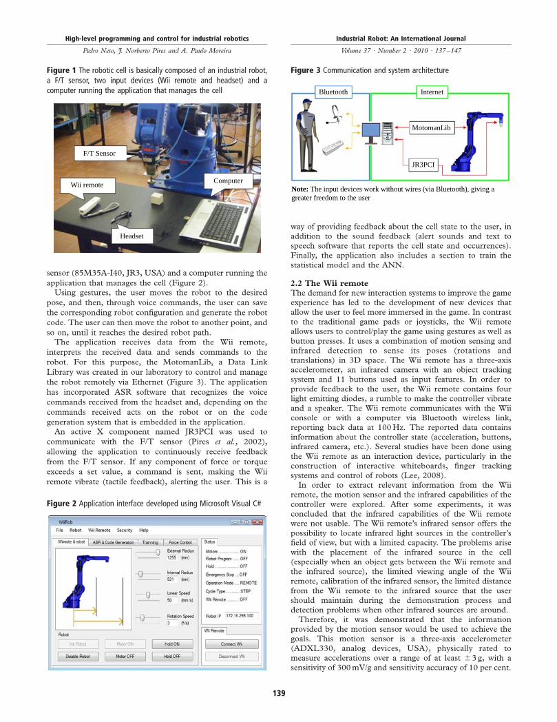
sensor (85M35A-I40, JR3, USA) and a computer running the
application that manages the cell (Figure 2).Using gestures, the user moves the robot to the desired
pose, and then, through voice commands, the user can save
the corresponding robot configuration and generate the robot
code. The user can then move the robot to another point, and
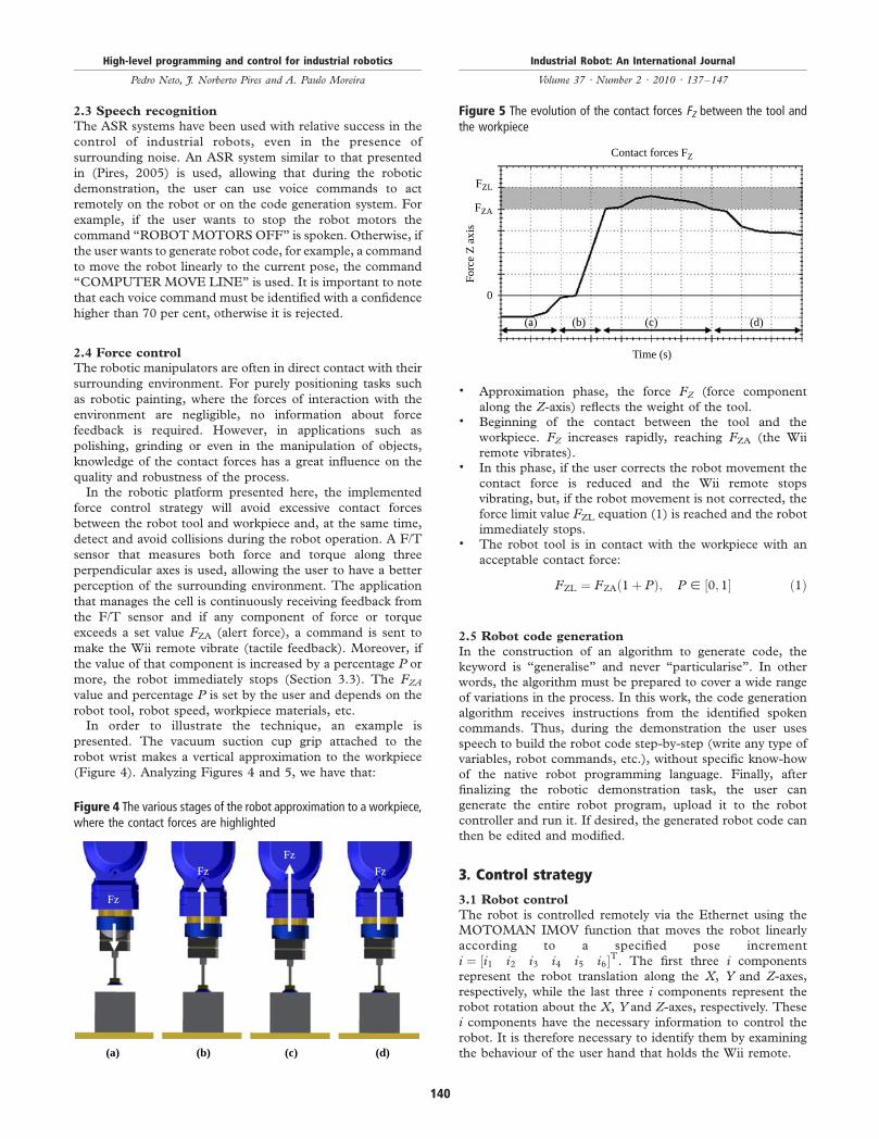
so on, until it reaches the desired robot path.The application receives data from the Wii remote,
interprets the received data and sends commands to the
robot. For this purpose, the MotomanLib, a Data Link
Library was created in our laboratory to control and manage
the robot remotely via Ethernet (Figure 3). The application
has incorporated ASR software that recognizes the voice
commands received from the headset and, depending on the
commands received acts on the robot or on the code
generation system that is embedded in the application.An active X component named JR3PCI was used to
communicate with the F/T sensor (Pires et al., 2002),
allowing the application to continuously receive feedback
from the F/T sensor. If any component of force or torque
exceeds a set value, a command is sent, making the Wii
remote vibrate (tactile feedback), alerting the user. This is a
way of providing feedback about the cell state to the user, inaddition to the sound feedback (alert sounds and text tospeech software that reports the cell state and occurrences).Finally, the application also includes a section to train thestatistical model and the ANN.
2.2 The Wii remote
The demand for new interaction systems to improve the gameexperience has led to the development of new devices thatallow the user to feel more immersed in the game. In contrastto the traditional game pads or joysticks, the Wii remoteallows users to control/play the game using gestures as well asbutton presses. It uses a combination of motion sensing andinfrared detection to sense its poses (rotations andtranslations) in 3D space. The Wii remote has a three-axisaccelerometer, an infrared camera with an object trackingsystem and 11 buttons used as input features. In order toprovide feedback to the user, the Wii remote contains fourlight emitting diodes, a rumble to make the controller vibrateand a speaker. The Wii remote communicates with the Wiiconsole or with a computer via Bluetooth wireless link,reporting back data at 100Hz. The reported data containsinformation about the controller state (acceleration, buttons,infrared camera, etc.). Several studies have been done usingthe Wii remote as an interaction device, particularly in theconstruction of interactive whiteboards, finger trackingsystems and control of robots (Lee, 2008).In order to extract relevant information from the Wii
remote, the motion sensor and the infrared capabilities of thecontroller were explored. After some experiments, it wasconcluded that the infrared capabilities of the Wii remotewere not usable. The Wii remote’s infrared sensor offers thepossibility to locate infrared light sources in the controller’sfield of view, but with a limited capacity. The problems arisewith the placement of the infrared source in the cell(especially when an object gets between the Wii remote andthe infrared source), the limited viewing angle of the Wiiremote, calibration of the infrared sensor, the limited distancefrom the Wii remote to the infrared source that the usershould maintain during the demonstration process anddetection problems when other infrared sources are around.Therefore, it was demonstrated that the information
provided by the motion sensor would be used to achieve thegoals. This motion sensor is a three-axis accelerometer(ADXL330, analog devices, USA), physically rated tomeasure accelerations over a range of at least ^3 g, with asensitivity of 300mV/g and sensitivity accuracy of 10 per cent.
Figure 1 The robotic cell is basically composed of an industrial robot,a F/T sensor, two input devices (Wii remote and headset) and acomputer running the application that manages the cell
F/T Sensor
Wii remote
Headset
Computer
Figure 2 Application interface developed using Microsoft Visual C#
Figure 3 Communication and system architecture
Bluetooth Internet
MotomanLib
JR3PCI
Note: The input devices work without wires (via Bluetooth), giving agreater freedom to the user
High-level programming and control for industrial robotics
Pedro Neto, J. Norberto Pires and A. Paulo Moreira
Industrial Robot: An International Journal
Volume 37 · Number 2 · 2010 · 137–147
139
2.3 Speech recognition
The ASR systems have been used with relative success in the
control of industrial robots, even in the presence of
surrounding noise. An ASR system similar to that presented
in (Pires, 2005) is used, allowing that during the robotic
demonstration, the user can use voice commands to act
remotely on the robot or on the code generation system. For
example, if the user wants to stop the robot motors the
command “ROBOTMOTORSOFF” is spoken. Otherwise, if
the user wants to generate robot code, for example, a command
to move the robot linearly to the current pose, the command
“COMPUTER MOVE LINE” is used. It is important to note
that each voice command must be identified with a confidence
higher than 70 per cent, otherwise it is rejected.
2.4 Force control
The robotic manipulators are often in direct contact with their
surrounding environment. For purely positioning tasks such
as robotic painting, where the forces of interaction with the
environment are negligible, no information about force
feedback is required. However, in applications such as
polishing, grinding or even in the manipulation of objects,
knowledge of the contact forces has a great influence on the
quality and robustness of the process.In the robotic platform presented here, the implemented
force control strategy will avoid excessive contact forces
between the robot tool and workpiece and, at the same time,
detect and avoid collisions during the robot operation. A F/T
sensor that measures both force and torque along three
perpendicular axes is used, allowing the user to have a better
perception of the surrounding environment. The application
that manages the cell is continuously receiving feedback from
the F/T sensor and if any component of force or torque
exceeds a set value FZA (alert force), a command is sent to
make the Wii remote vibrate (tactile feedback). Moreover, if
the value of that component is increased by a percentage P or
more, the robot immediately stops (Section 3.3). The FZA
value and percentage P is set by the user and depends on the
robot tool, robot speed, workpiece materials, etc.In order to illustrate the technique, an example is
presented. The vacuum suction cup grip attached to the
robot wrist makes a vertical approximation to the workpiece
(Figure 4). Analyzing Figures 4 and 5, we have that:
. Approximation phase, the force FZ (force component
along the Z-axis) reflects the weight of the tool.. Beginning of the contact between the tool and the
workpiece. FZ increases rapidly, reaching FZA (the Wii
remote vibrates).. In this phase, if the user corrects the robot movement the
contact force is reduced and the Wii remote stops
vibrating, but, if the robot movement is not corrected, the
force limit value FZL equation (1) is reached and the robot
immediately stops.. The robot tool is in contact with the workpiece with an
acceptable contact force:
FZL ¼ FZAð1þ PÞ; P [ ½0; 1� ð1Þ
2.5 Robot code generation
In the construction of an algorithm to generate code, the
keyword is “generalise” and never “particularise”. In other
words, the algorithm must be prepared to cover a wide range
of variations in the process. In this work, the code generation
algorithm receives instructions from the identified spoken
commands. Thus, during the demonstration the user uses
speech to build the robot code step-by-step (write any type of
variables, robot commands, etc.), without specific know-how
of the native robot programming language. Finally, after
finalizing the robotic demonstration task, the user can
generate the entire robot program, upload it to the robot
controller and run it. If desired, the generated robot code can
then be edited and modified.
3. Control strategy
3.1 Robot control
The robot is controlled remotely via the Ethernet using the
MOTOMAN IMOV function that moves the robot linearly
according to a specified pose increment
i ¼ ½i1 i2 i3 i4 i5 i6�T. The first three i components
represent the robot translation along the X, Y and Z-axes,
respectively, while the last three i components represent the
robot rotation about the X, Y and Z-axes, respectively. These
i components have the necessary information to control the
robot. It is therefore necessary to identify them by examining
the behaviour of the user hand that holds the Wii remote.
Figure 4 The various stages of the robot approximation to a workpiece,where the contact forces are highlighted
Fz
Fz
Fz
Fz
(a) (b) (c) (d)
Figure 5 The evolution of the contact forces FZ between the tool andthe workpiece
Contact forces FZ
Time (s)
(a) (b) (c) (d)
FZL
FZA
0
Forc
e Z
axi
s
High-level programming and control for industrial robotics
Pedro Neto, J. Norberto Pires and A. Paulo Moreira
Industrial Robot: An International Journal
Volume 37 · Number 2 · 2010 · 137–147
140
In this system, it is completely unnecessary to extract
precise displacements or rotations, being only required to
know which of the pose increment components must be
activated. In a first approach, the robot control strategy was to
identify translation movements and rotations of the user hand
and, depending on these inputs, small pose increments were
continuously sent to the robot. However, it was quickly
concluded that this approach was not viable because the robot
was constantly halting, presenting a high-level of “vibration”.
The achieved solution was to send to the robot only one pose
increment that will move the robot to the limit of the field of
operation.The robot movement is activated by pressing the Wii
remote B button and making a hand gesture or posture
according to the desired robot movement. After this, if a
gesture is recognized, the robot starts the movement and
when the user releases the B button the robot stops. If the B
button is never released, the robot continues the movement
up to the limit of its field of operation. If a gesture is not
recognized, the robot remains stopped.
3.2 Field of operation of the robot – increment
calculation
According to the user hand behaviour, the robot is moved to
the limit of its field of operation, or more specifically, for a
pose close to the limit of the field of operation. The field of
operation of a six-DOF robot manipulator is approximately a
volume region bounded by two spherical surfaces. This way, it
can be considered that the field of operation of the robot is
bounded by two spherical surfaces equation (2), both with the
centre coincident with the zero reference point of the robot,
and where Rext and Rint are, respectively, the radius of the
external and internal spherical surface:
x2 þ y2 þ z2 # R2ext
x2 þ y2 þ z2 $ R2int
8<: ð2Þ
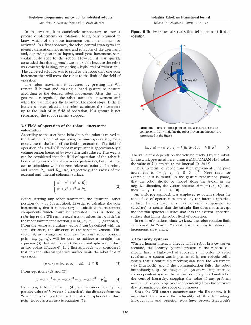
Before starting any robot movement, the “current” robot
position (xr, yr, zr) is acquired. In order to calculate the pose
increment i, first it is necessary to calculate the increment
components which must be activated. This is done by
referring to the Wii remote acceleration values that will define
the robot movement direction a ¼ (ax, ay, az 2 1) (Section 4).
From the vector a, a unitary vector u can be defined with the
same direction, the direction of the robot movement. This
vector u, in conjugation with the “current” robot position
point (xr, yr, zr), will be used to achieve a straight line
equation (3) that will intersect the external spherical surface
at two points (Figure 6). In a first approach, it is considered
that only the external spherical surface limits the robot field of
operation:
ðx; y; zÞ ¼ ðxr; yr; zrÞ þ ku; k [ R ð3Þ
From equations (2) and (3):
ðxr þ ku1Þ2 þ ðyr þ ku2Þ2 þ ðzr þ ku3Þ2 ¼ R2ext ð4Þ
Extracting k from equation (4), and considering only the
positive value of k (vector u direction), the distance from the
“current” robot position to the external spherical surface
point (robot increment) is equation (5):
ðx; y; zÞ ¼ ði1; i2; i3Þ ¼ kðu1; u2; u3Þ; k [ Rþ ð5Þ
The value of k depends on the volume reached by the robot.
In the work presented here, using a MOTOMAN HP6 robot,
the value of k is limited to the interval [0, 2012].Thus, in terms of robot translation movements, the pose
increment is i ¼ ½i1 i2 i3 0 0 0�T. Note that, for
example, if it is found (in the gesture recognition phase)
that the robot should be moved along the X-axis in the
negative direction, the vector becomes u ¼ (21, 0, 0), and
then i ¼ ½i1 0 0 0 0 0�T.An analogue approach was employed to obtain i when the
robot field of operation is limited by the internal spherical
surface. In this case, if k has no value (impossible to
calculate), it means that the straight line does not intercept
the internal spherical surface and it is the external spherical
surface that limits the robot field of operation.In terms of rotations, since we know the robot rotation limit
values and the “current” robot pose, it is easy to obtain the
increments i4, i5 and i6.
3.3 Security systems
When a human interacts directly with a robot in a co-worker
scenario, the security systems present in the robotic cell
should have a high-level of robustness, in order to avoid
accidents. A system was implemented in our robotic cell a
system that is continually receiving data from the Wii remote
(via Bluetooth) and if the communication fails, the robot
immediately stops. An independent system was implemented
an independent system that actuates directly in a low-level of
the control hierarchy, stopping the robot if any problem
occurs. This system operates independently from the software
that is running on the robot or computer.Since the Wii remote communicates via Bluetooth, it is
important to discuss the reliability of this technology.
Investigations and practical tests have proven Bluetooth’s
Figure 6 The two spherical surfaces that define the robot field ofoperation
Z
(az–1)
ay
ax (xr,yr ,zr)
Y
Note: The “current” robot point and the acceleration vectorcomponents that will define the robot movement direction arerepresented in the figure
X
High-level programming and control for industrial robotics
Pedro Neto, J. Norberto Pires and A. Paulo Moreira
Industrial Robot: An International Journal
Volume 37 · Number 2 · 2010 · 137–147
141
reliability, but caution should be exercised when installingBluetooth products. Important issues are interference withother Bluetooth nodes, radio standards and sources ofradiation (industrial equipment or commercial devices likemicrowave ovens). Thus, considering the high demands forsafety and real-time performance in industry, this technologymust be used with care.
4. Posture and gesture recognition
4.1 Modes of operation
The developed system has two distinct modes of operationthat the user can select during the demonstration phase. In thefirst mode, the robot moves along the X, Y and Z-axesseparately, while in the other mode the robot can move alongthe three axes at the same time. In terms of rotations, in bothcases, the rotation around each of the three axes is doneseparately, an axis at a time.The accelerations extracted from the three-axis
accelerometer (ax, ay, az) will be used to detect the userhand gestures and postures. When the Wii remote is operatingin a dynamic way, the gravity components will appear mixedwith the inertial components of acceleration. In order toprevent this situation, when the user makes gestures, the Wiiremote must be kept horizontal (Figure 7). Thus, it is knownthat the force of gravity acts along the Z-axis. For example, tomove the robot in the X-direction, the user should move theWii remote along the X-axis, keeping it in the horizontal.
4.2 Recognition of gestures and postures
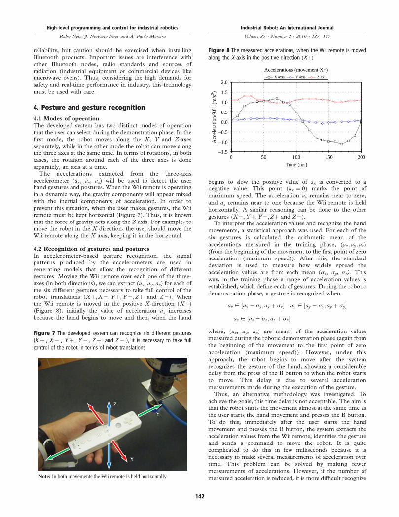
In accelerometer-based gesture recognition, the signalpatterns produced by the accelerometers are used ingenerating models that allow the recognition of differentgestures. Moving the Wii remote over each one of the three-axes (in both directions), we can extract (ax, ay, az) for each ofthe six different gestures necessary to take full control of therobot translations ðXþ;X2;Yþ;Y2;Zþ and Z2Þ. Whenthe Wii remote is moved in the positive X-direction ðXþÞ(Figure 8), initially the value of acceleration ax increasesbecause the hand begins to move and then, when the hand
begins to slow the positive value of ax is converted to a
negative value. This point ðax ¼ 0Þ marks the point of
maximum speed. The acceleration ay remains near to zero,
and az remains near to one because the Wii remote is held
horizontally. A similar reasoning can be done to the other
gestures ðX2;Yþ;Y2;Zþ and Z2Þ.To interpret the acceleration values and recognize the hand
movements, a statistical approach was used. For each of the
six gestures is calculated the arithmetic mean of the
accelerations measured in the training phase, (�ax; �ay; �az)(from the beginning of the movement to the first point of zero
acceleration (maximum speed)). After this, the standard
deviation is used to measure how widely spread the
acceleration values are from each mean (sx, sy, sz). This
way, in the training phase a range of acceleration values is
established, which define each of gestures. During the robotic
demonstration phase, a gesture is recognized when:
ax [ ½�ax 2 sx; �ax þ sx� ay [ ½�ay 2 sy; �ay þ sy�
az [ ½�az 2 sz; �az þ sz�
where, (ax, ay, az) are means of the acceleration values
measured during the robotic demonstration phase (again from
the beginning of the movement to the first point of zero
acceleration (maximum speed)). However, under this
approach, the robot begins to move after the system
recognizes the gesture of the hand, showing a considerable
delay from the press of the B button to when the robot starts
to move. This delay is due to several acceleration
measurements made during the execution of the gesture.Thus, an alternative methodology was investigated. To
achieve the goals, this time delay is not acceptable. The aim is
that the robot starts the movement almost at the same time as
the user starts the hand movement and presses the B button.
To do this, immediately after the user starts the hand
movement and presses the B button, the system extracts the
acceleration values from the Wii remote, identifies the gesture
and sends a command to move the robot. It is quite
complicated to do this in few milliseconds because it is
necessary to make several measurements of acceleration over
time. This problem can be solved by making fewer
measurements of accelerations. However, if the number of
measured acceleration is reduced, it is more difficult recognize
Figure 7 The developed system can recognize six different gestures(X þ , X 2 , Y þ , Y 2 , Z þ and Z 2 ), it is necessary to take fullcontrol of the robot in terms of robot translations
Z
Y
X
Note: In both movements the Wii remote is held horizontally
Figure 8 The measured accelerations, when the Wii remote is movedalong the X-axis in the positive direction ðXþÞ
2.0
1.5
1.0
0.5
0.0
–0.5
–1.0
–1.50 50 100
Time (ms)
200150
X axis Y axis
Accelerations (movement X+)
Acc
eler
atio
n/9.
81 (
m/s
2 )
Z axis
High-level programming and control for industrial robotics
Pedro Neto, J. Norberto Pires and A. Paulo Moreira
Industrial Robot: An International Journal
Volume 37 · Number 2 · 2010 · 137–147
142
a gesture and the recognition rate becomes low. The goal is to
achieve a compromise between the time delay, and theachieved recognition rate. After some experiments were doneto evaluate the system response time, it was decided to extractfrom the accelerometer only the first four measurements of
acceleration that constitute an input pattern. A gesture isidentified by comparing the extracted acceleration values withthe values acquired in the training phase, following the samestatistical approach outlined above. This alternativemethodology was then developed using ANNs.In the second mode of operation, the robot is moved
linearly along the direction that the user hand demonstrates,in other words, the vector of accelerations a ¼ (ax, ay, az 2 1)
will directly define the robot movement direction. The vectora is extracted immediately after the user starts the handmovement and presses the B button (this vector is defined as amean of the four first measurements of acceleration). Thethird component of a is (az 2 1) since the Wii remote is held
horizontally, reporting an acceleration along the Z-axis.Besides, the robot translations, the robot control
architecture needs also to have as input six different robot
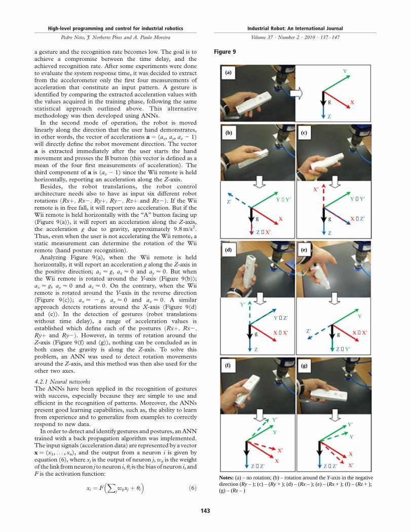
rotations ðRxþ; Rx2; Ryþ; Ry2; Rzþ and Rz2Þ. If the Wiiremote is in free fall, it will report zero acceleration. But if theWii remote is held horizontally with the “A” button facing up(Figure 9(a)), it will report an acceleration along the Z-axis,the acceleration g due to gravity, approximately 9.8m/s2.
Thus, even when the user is not accelerating the Wii remote, astatic measurement can determine the rotation of the Wiiremote (hand posture recognition).Analyzing Figure 9(a), when the Wii remote is held
horizontally, it will report an acceleration g along the Z-axis inthe positive direction; az < g, ax < 0 and ay < 0. But whenthe Wii remote is rotated around the Y-axis (Figure 9(b));ax < g, ay < 0 and az < 0. On the contrary, when the Wii
remote is rotated around the Y-axis in the reverse direction(Figure 9(c)); ax < 2 g, ay < 0 and az < 0. A similarapproach detects rotations around the X-axis (Figure 9(d)and (e)). In the detection of gestures (robot translationswithout time delay), a range of acceleration values is
established which define each of the postures ðRxþ; Rx2;Ryþ and Ry2Þ. However, in terms of rotation around theZ-axis (Figure 9(f) and (g)), nothing can be concluded as inboth cases the gravity is along the Z-axis. To solve this
problem, an ANN was used to detect rotation movementsaround the Z-axis, and this method was then also used for theother two axes.
4.2.1 Neural networksThe ANNs have been applied in the recognition of gestureswith success, especially because they are simple to use and
efficient in the recognition of patterns. Moreover, the ANNspresent good learning capabilities, such as, the ability to learnfrom experience and to generalize from examples to correctlyrespond to new data.In order to detect and identify gestures and postures, anANN
trained with a back propagation algorithm was implemented.The input signals (acceleration data) are represented by a vector
x ¼ (x1, . . . , xn), and the output from a neuron i is given byequation (6), where xj is the output of neuron j, wij is the weightof the link fromneuron j to neuron i, ui is the bias of neuron i, andF is the activation function:
xi ¼ FX
jwijxj þ ui
� �ð6Þ
Figure 9
(a)
(b) (c)
Y
Xg
Z
Y ≡ Y′ Y ≡ Y′
Z ≡ Y′
Y ≡ Z′
Z ≡ X′
Z ≡ Z′ Z ≡ Z′
X ≡ Z′X
Y′
Y′
X′
X′
X′X
X
X ≡ X′ X ≡ X′
g g
gg
Z′
Z
Z
Z′
(e)(d)
(g)(f)
Y
Y
Y′
Y
Notes: (a) – no rotation; (b) – rotation around the Y-axis in the negativedirection (Ry – ); (c) – (Ry + ); (d) – (Rx – ); (e) – (Rx + ); (f) – (Rz + );(g) – (Rz – )
High-level programming and control for industrial robotics
Pedro Neto, J. Norberto Pires and A. Paulo Moreira
Industrial Robot: An International Journal
Volume 37 · Number 2 · 2010 · 137–147
143
It is now necessary to find the weights of the network. The back
propagation algorithm is used as a learning algorithm to
determine the weights of a network, in other words, themethod
adjust the weights to minimize the errors. These errors can be
determined from the input neurons (training set of several
patterns) and the desired output vector. The error is achieved
comparing the desired output (obtained in the training phase)
with the actual output. This methodology presupposes that
gestures trained for performing certain functions are alwaysrepeated as they were trained.
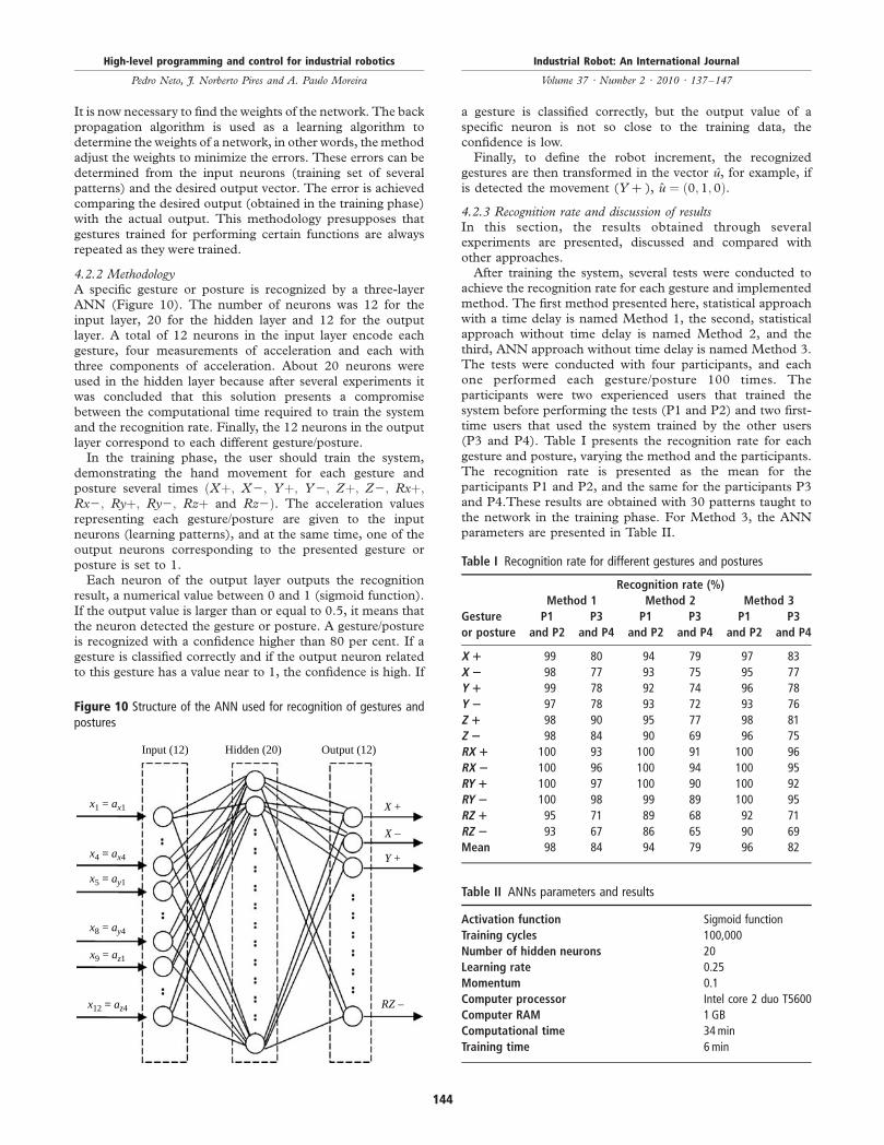
4.2.2 MethodologyA specific gesture or posture is recognized by a three-layer
ANN (Figure 10). The number of neurons was 12 for the
input layer, 20 for the hidden layer and 12 for the outputlayer. A total of 12 neurons in the input layer encode each
gesture, four measurements of acceleration and each with
three components of acceleration. About 20 neurons were
used in the hidden layer because after several experiments it
was concluded that this solution presents a compromise
between the computational time required to train the system
and the recognition rate. Finally, the 12 neurons in the output
layer correspond to each different gesture/posture.In the training phase, the user should train the system,
demonstrating the hand movement for each gesture and
posture several times ðXþ; X2; Yþ; Y2; Zþ; Z2; Rxþ;Rx2; Ryþ; Ry2; Rzþ and Rz2Þ. The acceleration values
representing each gesture/posture are given to the input
neurons (learning patterns), and at the same time, one of theoutput neurons corresponding to the presented gesture or
posture is set to 1.Each neuron of the output layer outputs the recognition
result, a numerical value between 0 and 1 (sigmoid function).
If the output value is larger than or equal to 0.5, it means that
the neuron detected the gesture or posture. A gesture/postureis recognized with a confidence higher than 80 per cent. If a
gesture is classified correctly and if the output neuron related
to this gesture has a value near to 1, the confidence is high. If
a gesture is classified correctly, but the output value of a
specific neuron is not so close to the training data, theconfidence is low.Finally, to define the robot increment, the recognized
gestures are then transformed in the vector u, for example, if
is detected the movement (Y þ ), u ¼ ð0; 1; 0Þ.
4.2.3 Recognition rate and discussion of resultsIn this section, the results obtained through severalexperiments are presented, discussed and compared with
other approaches.After training the system, several tests were conducted to
achieve the recognition rate for each gesture and implementedmethod. The first method presented here, statistical approach
with a time delay is named Method 1, the second, statisticalapproach without time delay is named Method 2, and the
third, ANN approach without time delay is named Method 3.The tests were conducted with four participants, and eachone performed each gesture/posture 100 times. The
participants were two experienced users that trained thesystem before performing the tests (P1 and P2) and two first-
time users that used the system trained by the other users(P3 and P4). Table I presents the recognition rate for each
gesture and posture, varying the method and the participants.The recognition rate is presented as the mean for the
participants P1 and P2, and the same for the participants P3and P4.These results are obtained with 30 patterns taught to
the network in the training phase. For Method 3, the ANNparameters are presented in Table II.
Figure 10 Structure of the ANN used for recognition of gestures andpostures
Input (12)
x1 = ax1
x4 = ax4
x5 = ay1
x8 = ay4
x9 = az1
x12 = az4
Hidden (20) Output (12)
X +
X –
Y +
RZ –
Table I Recognition rate for different gestures and postures
Recognition rate (%)
Method 1 Method 2 Method 3
Gesture
or posture
P1
and P2
P3
and P4
P1
and P2
P3
and P4
P1
and P2
P3
and P4
X 1 99 80 94 79 97 83
X 2 98 77 93 75 95 77
Y 1 99 78 92 74 96 78
Y 2 97 78 93 72 93 76
Z 1 98 90 95 77 98 81
Z 2 98 84 90 69 96 75
RX 1 100 93 100 91 100 96
RX 2 100 96 100 94 100 95
RY 1 100 97 100 90 100 92
RY 2 100 98 99 89 100 95
RZ 1 95 71 89 68 92 71
RZ 2 93 67 86 65 90 69
Mean 98 84 94 79 96 82
Table II ANNs parameters and results
Activation function Sigmoid function
Training cycles 100,000
Number of hidden neurons 20
Learning rate 0.25
Momentum 0.1
Computer processor Intel core 2 duo T5600
Computer RAM 1 GB
Computational time 34 min
Training time 6 min
High-level programming and control for industrial robotics
Pedro Neto, J. Norberto Pires and A. Paulo Moreira
Industrial Robot: An International Journal
Volume 37 · Number 2 · 2010 · 137–147
144
In Method 1, the experiments showed a recognition rate of
98 per cent for the participants P1 and P2, and 84 per cent for
the participants P3 and P4. The Methods 2 and 3 do not
present such a good average of correctly recognized gestures,
but in compensation do not have the time delay, which is
crucial in the system. Method 3 (ANN approach without time
delay) was shown to be the best solution, with a recognition
rate of 96 per cent for the participants P1 and P2, and
82 per cent for the participants P3 and P4. For P1 and P2,
even the lowest recognition rate of the gesture RZ 2 is
90 per cent. It was concluded that the participants P1 and
P2 present better results than the participants P3 and P4,
demonstrating the necessity for each user to train the system
before using it. However, the aim is that the time spent in the
training should be minimal. The users do not want to spend
time demonstrating gestures and postures to the system, but
at the same time it is necessary to keep a compromise with the
recognition rate.The recognition rate of the output depends a lot on the
samples provided during the training phase (learning patterns).
Given that Method 3 proved to be a good solution, several
experiments were made to test its performance when the
number of samples given to the ANN in the training phase is
changed. In Table III are presented the results, keeping the
parameters of the ANN described in Table II. It was found that
the model requires 30 samples per gesture to achieve an
accuracy of about 96 per cent, but if the number of learning
patterns is increased to 60 or 70, the recognition rate is
improved but not significantly. Giving 30 patterns to the system
the user takes 6min in the training phase, and with 60 patterns
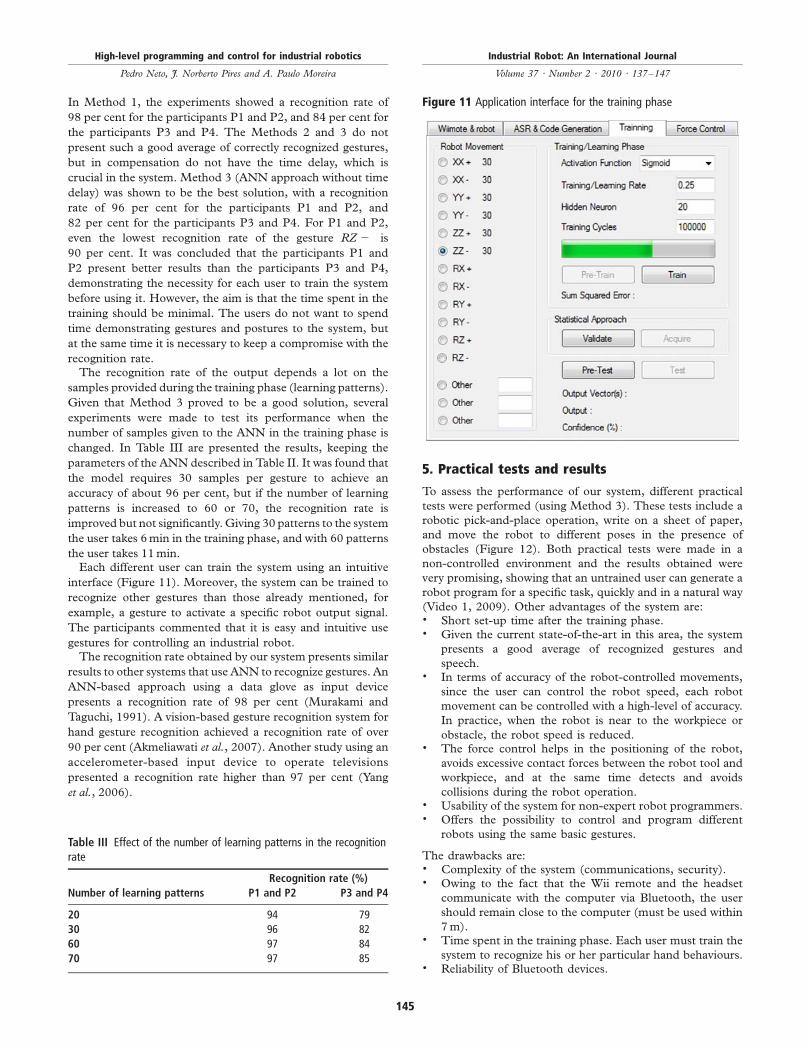
the user takes 11min.Each different user can train the system using an intuitive
interface (Figure 11). Moreover, the system can be trained to
recognize other gestures than those already mentioned, for
example, a gesture to activate a specific robot output signal.
The participants commented that it is easy and intuitive use
gestures for controlling an industrial robot.The recognition rate obtained by our system presents similar
results to other systems that use ANN to recognize gestures. An
ANN-based approach using a data glove as input device
presents a recognition rate of 98 per cent (Murakami and
Taguchi, 1991). A vision-based gesture recognition system for
hand gesture recognition achieved a recognition rate of over
90 per cent (Akmeliawati et al., 2007). Another study using an
accelerometer-based input device to operate televisions
presented a recognition rate higher than 97 per cent (Yang
et al., 2006).
5. Practical tests and results
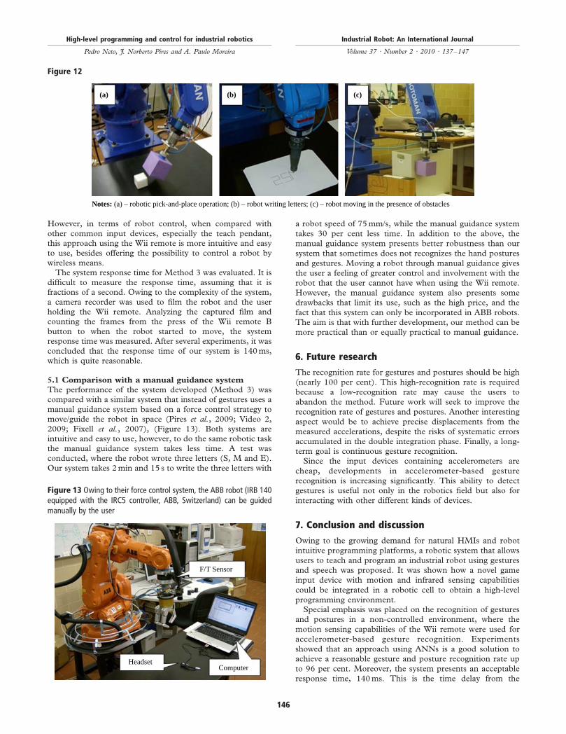
To assess the performance of our system, different practical
tests were performed (using Method 3). These tests include a
robotic pick-and-place operation, write on a sheet of paper,
and move the robot to different poses in the presence of
obstacles (Figure 12). Both practical tests were made in a
non-controlled environment and the results obtained were
very promising, showing that an untrained user can generate a
robot program for a specific task, quickly and in a natural way
(Video 1, 2009). Other advantages of the system are:. Short set-up time after the training phase.. Given the current state-of-the-art in this area, the system
presents a good average of recognized gestures and
speech.. In terms of accuracy of the robot-controlled movements,
since the user can control the robot speed, each robot
movement can be controlled with a high-level of accuracy.
In practice, when the robot is near to the workpiece or
obstacle, the robot speed is reduced.. The force control helps in the positioning of the robot,
avoids excessive contact forces between the robot tool and
workpiece, and at the same time detects and avoids
collisions during the robot operation.. Usability of the system for non-expert robot programmers.. Offers the possibility to control and program different
robots using the same basic gestures.
The drawbacks are:. Complexity of the system (communications, security).. Owing to the fact that the Wii remote and the headset
communicate with the computer via Bluetooth, the user
should remain close to the computer (must be used within
7m).. Time spent in the training phase. Each user must train the
system to recognize his or her particular hand behaviours.. Reliability of Bluetooth devices.
Figure 11 Application interface for the training phase
Table III Effect of the number of learning patterns in the recognitionrate
Recognition rate (%)
Number of learning patterns P1 and P2 P3 and P4
20 94 79
30 96 82
60 97 84
70 97 85
High-level programming and control for industrial robotics
Pedro Neto, J. Norberto Pires and A. Paulo Moreira
Industrial Robot: An International Journal
Volume 37 · Number 2 · 2010 · 137–147
145
However, in terms of robot control, when compared with
other common input devices, especially the teach pendant,this approach using the Wii remote is more intuitive and easyto use, besides offering the possibility to control a robot by
wireless means.The system response time for Method 3 was evaluated. It is
difficult to measure the response time, assuming that it isfractions of a second. Owing to the complexity of the system,
a camera recorder was used to film the robot and the userholding the Wii remote. Analyzing the captured film andcounting the frames from the press of the Wii remote B
button to when the robot started to move, the systemresponse time was measured. After several experiments, it was
concluded that the response time of our system is 140ms,which is quite reasonable.
5.1 Comparison with a manual guidance system
The performance of the system developed (Method 3) wascompared with a similar system that instead of gestures uses a
manual guidance system based on a force control strategy tomove/guide the robot in space (Pires et al., 2009; Video 2,
2009; Fixell et al., 2007), (Figure 13). Both systems areintuitive and easy to use, however, to do the same robotic taskthe manual guidance system takes less time. A test was
conducted, where the robot wrote three letters (S, M and E).Our system takes 2min and 15 s to write the three letters with
a robot speed of 75mm/s, while the manual guidance system
takes 30 per cent less time. In addition to the above, the
manual guidance system presents better robustness than our
system that sometimes does not recognizes the hand postures
and gestures. Moving a robot through manual guidance gives
the user a feeling of greater control and involvement with the
robot that the user cannot have when using the Wii remote.
However, the manual guidance system also presents some
drawbacks that limit its use, such as the high price, and the
fact that this system can only be incorporated in ABB robots.
The aim is that with further development, our method can be
more practical than or equally practical to manual guidance.
6. Future research
The recognition rate for gestures and postures should be high
(nearly 100 per cent). This high-recognition rate is required
because a low-recognition rate may cause the users to
abandon the method. Future work will seek to improve the
recognition rate of gestures and postures. Another interesting
aspect would be to achieve precise displacements from the
measured accelerations, despite the risks of systematic errors
accumulated in the double integration phase. Finally, a long-
term goal is continuous gesture recognition.Since the input devices containing accelerometers are
cheap, developments in accelerometer-based gesture
recognition is increasing significantly. This ability to detect
gestures is useful not only in the robotics field but also for
interacting with other different kinds of devices.
7. Conclusion and discussion
Owing to the growing demand for natural HMIs and robot
intuitive programming platforms, a robotic system that allows
users to teach and program an industrial robot using gestures
and speech was proposed. It was shown how a novel game
input device with motion and infrared sensing capabilities
could be integrated in a robotic cell to obtain a high-level
programming environment.Special emphasis was placed on the recognition of gestures
and postures in a non-controlled environment, where the
motion sensing capabilities of the Wii remote were used for
accelerometer-based gesture recognition. Experiments
showed that an approach using ANNs is a good solution to
achieve a reasonable gesture and posture recognition rate up
to 96 per cent. Moreover, the system presents an acceptable
response time, 140ms. This is the time delay from the
Figure 13 Owing to their force control system, the ABB robot (IRB 140equipped with the IRC5 controller, ABB, Switzerland) can be guidedmanually by the user
F/T Sensor
HeadsetComputer
Figure 12
(a) (b) (c)
Notes: (a) – robotic pick-and-place operation; (b) – robot writing letters; (c) – robot moving in the presence of obstacles
High-level programming and control for industrial robotics
Pedro Neto, J. Norberto Pires and A. Paulo Moreira
Industrial Robot: An International Journal
Volume 37 · Number 2 · 2010 · 137–147
146
moment the user starts to perform the gesture until the robot
starts to move.The Wii remote is an off-the-shelf product, available in the
market at a low price. Using this and other standard
technologies means that future innovation will be faster and
less expensive. Finally, most of users found it natural and
intuitive to use gestures for controlling an industrial robot.
References
Akmeliawati, R., Ooi, M.P.L. and Kuang, Y.C. (2007), “Real-
time Malaysian sign language translation using colour
segmentation and neural network”, Instrumentation andMeasurement Technology Conference (IMTC 2007), pp. 1-6.
Aleotti, J., Skoglund, A. and Duckett, T. (2004), “Position
teaching of a robot arm by demonstration with a wearable
input device”, paper presented at the International
Conference on Intelligent Manipulation and Grasping
(IMG04), Genoa.Bischoff, R., Kazi, A. and Seyfarth, M. (2002), “The
MORPHA style guide for icon-based programming”, The11th IEEE International Symposium on Robot and HumanInteractive Communication, pp. 482-7.
Calcagno, R., Rusina, F., Deregibus, F., Vincentelli, A.S. and
Bonivento, A. (2006), “Applications of wireless
technologies in automotive production systems”, VDIBerichte, Vol. 1956, pp. 57-8.
Chen,X., Zhang,X., Zhao,Z., Yang, J., Lantz, V. andWang,K.
(2007), “Hand gesture recognition research based on surface
EMG sensors and 2D-accelerometrs”, 11th IEEEInternational Symposium on Wearable Computers, pp. 11-14.
Cravotta, R. (2007), “Recognizing gestures. Blurring the line
between humans and machines”, EDN Europe, August 16.Dillmann, R. (2004), “Teaching and learning of robot tasks
via observation of human performance”, Robotics andAutonomous Systems, Vol. 47 Nos 2/3, pp. 109-16.
Fixell, P., Groth, T., Isaksson, M., Zhang, H., Wang, J., He, J.,
Kohlmaier, M., Krappinger, R. and Ge, J. (2007), “Force
control turns machining robots into universal tools”, ABBReview, Vol. 4, pp. 22-5.
Hein, B., Hensel, M. and Worn, H. (2008), “Intuitive and
model-based on-line programming of industrial robots:
a modular on-line programming environment”, IEEEInternational Conference on Robotics and Automation,pp. 3952-7.
Hirzinger, G., Bals, J., Otter, M. and Stelter, J. (2005), “The
DLR-KUKA success story: robotics research improves
industrial robots”, IEEE Robotics & Automation Magazine,Vol. 12 No. 3, pp. 16-23.
Kela, J., Korpipaa, P., Mantyjarvi, J., Kallio, S., Savino, G.,
Jozzo, L. and Di Marca, S. (2006), “Accelerometer-based
gesture control for a design environment”, Personal andUbiquitous Computing, Vol. 10 No. 5, pp. 285-99.
Lee, J.C. (2008), “Hacking the Nintendo Wii remote”,
Pervasive Computing IEEE, Vol. 7 No. 3, pp. 39-45.Mantyla, V., Mantyjarvi, J., Seppanen, T. and Tuulari, E.
(2000), “Hand gesture recognition of a mobile device
user”, IEEE International Conference on Multimedia and Expo(ICME 2000), Vol. 1, pp. 281-4.
Mihara, I., Yamauchi, Y. and Doi, M. (2003), “A real-timevision-based interface using motion processor andapplications to robotics”, Systems and Computers in Japan,Vol. 34, pp. 10-19.
Murakami, K. and Taguchi, H. (1991), “Gesture recognitionusing recurrent neural networks”, Proceedings of ACMCHI’91 Conference on Human Factors in Computing Systems,pp. 237-42.
Nagata,F.,Watanabe,K.,Kiguchi,K.,Tsuda,K.,Kawaguchi,S.,Noda,Y. andKomino,M. (2001), “Joystick teaching system forpolishing robots using fuzzy compliance control”, IEEEInternational Symposium on Computational Intelligence inRobotics and Automation, pp. 362-7.
Neto, P., Pires, J.N. and Moreira, A.P. (2009),“Accelerometer-based control of an industrial roboticarm”, The 18th IEEE International Symposium on Robotand Human Interactive Communication, pp. 1192-7.
Perrin, S., Cassinelli, A. and Ishikawa, M. (2004), “Gesturerecognition using laser-based tracking system”, Sixth IEEEInternational Conference on Automatic Face and GestureRecognition, pp. 541-6.
Pires, J.N. (2005), “Robot-by-voice: experiments oncommanding an industrial robot using the human voice”,Industrial Robot, Vol. 32 No. 6, pp. 505-11.
Pires, J.N., Godinho, T. and Araujo, R. (2007), “Using digitalpens to program welding tasks”, Industrial Robot, Vol. 34No. 6, pp. 476-86.
Pires, J.N., Veiga, G. and Araujo, R. (2009), “Programming-by-demonstration in the coworker scenario for SMEs”,Industrial Robot, Vol. 36 No. 1, pp. 73-83.
Pires, J.N., Ramming, J., Rauch, S. and Araujo, R. (2002),“Force/torque sensing applied to industrial roboticdeburring”, Sensor Review Journal, Vol. 22No. 3, pp. 232-41.
Video 1 (2009), available at: http://robotics.dem.uc.pt/pedro.neto/GS1.html
Video 2 (2009), available at: http://robotics.dem.uc.pt/pedro.neto/PBD.html
Waldherr, S., Romero, R. and Thrun, S. (2000), “A gesturebased interface for human-robot interaction”, AutonomousRobots, Vol. 9 No. 2, pp. 151-73.
Watanabe, T., Yamagishi, S., Murakami, H., Furuse, N.,Hoshimiya, N. and Handa, Y. (2001), “Recognition oflower limb movements by artificial neural network forrestoring gait of hemiplegic patients by functional electricalstimulation”, 23rd Annual EMBS International Conference,pp. 1348-51.
Yang, J., Bang, W., Choi, E., Cho, S., Oh, J., Cho, J., Kim, S.,Ki, E. and Kim, D. (2006), “A 3D hand-drawn gesture inputdevice using fuzzy ARTMAP-based recognizer”, Journal ofSystemics, Cybernetics and Informatics, Vol. 4 No. 3, pp. 1-7.
Further reading
Hagan, M., Demuth, H. and Beale, M. (1996), NeuralNetwork Design, PWS Publishing, Boston, MA.
Corresponding author
Pedro Neto can be contacted at: [email protected]
High-level programming and control for industrial robotics
Pedro Neto, J. Norberto Pires and A. Paulo Moreira
Industrial Robot: An International Journal
Volume 37 · Number 2 · 2010 · 137–147
147
To purchase reprints of this article please e-mail: [email protected]
Or visit our web site for further details: www.emeraldinsight.com/reprints


![International Journal of Productivity and Performance ... · srm:616458 [] For Authors If you would like to write for this, or any other Emerald publication, then please use our Emerald](https://img.pdfslide.us/doc/110x75/601ccbd889c15b32262bd7a6/international-journal-of-productivity-and-performance-srm616458-for-authors.jpg)


![International Journal of Organizational Analysis...Access to this document was granted through an Emerald subscription provided by emerald-srm:401304 [] For Authors If you would like](https://img.pdfslide.us/doc/110x75/60ab3a132b41ba2ee90444ac/international-journal-of-organizational-analysis-access-to-this-document-was.jpg)