Embed Size (px)
Citation preview

Industrial Refrigeration systems in Potentially Explosive Atmospheres (Hazardous area) ATEX 94/9/EC Directive [ATmosphères EXplosives]
Application GuideREFRIGERATION & AIR CONDITIONING DIVISION
Application guide Industrial Refrigeration systems in Potentially Explosive Atmospheres (Hazardous area)
2 DKRCI.PA.000.A2.02 / 520H1296 © Danfoss A/S (RA Marketing/MWA), 10 - 2007
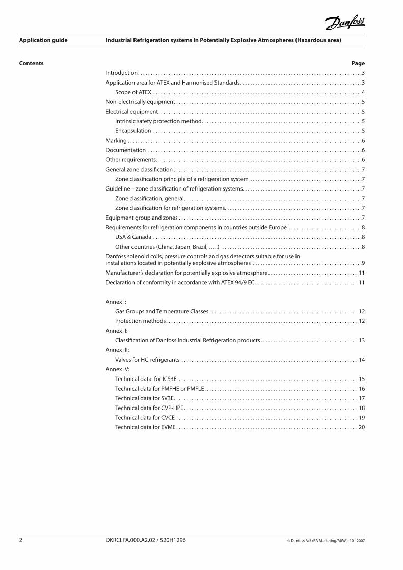
Contents Page
Introduction. . . . . . . . . . . . . . . . . . . . . . . . . . . . . . . . . . . . . . . . . . . . . . . . . . . . . . . . . . . . . . . . . . . . . . . . . . . . . . . . . . . . . . . .3
Application area for ATEX and Harmonised Standards. . . . . . . . . . . . . . . . . . . . . . . . . . . . . . . . . . . . . . . . . . . . . . . .3
Scope of ATEX . . . . . . . . . . . . . . . . . . . . . . . . . . . . . . . . . . . . . . . . . . . . . . . . . . . . . . . . . . . . . . . . . . . . . . . . . . . . . . . . . .4
Non-electrically equipment . . . . . . . . . . . . . . . . . . . . . . . . . . . . . . . . . . . . . . . . . . . . . . . . . . . . . . . . . . . . . . . . . . . . . . . . .5
Electrical equipment. . . . . . . . . . . . . . . . . . . . . . . . . . . . . . . . . . . . . . . . . . . . . . . . . . . . . . . . . . . . . . . . . . . . . . . . . . . . . . . .5
Intrinsic safety protection method. . . . . . . . . . . . . . . . . . . . . . . . . . . . . . . . . . . . . . . . . . . . . . . . . . . . . . . . . . . . . . .5
Encapsulation . . . . . . . . . . . . . . . . . . . . . . . . . . . . . . . . . . . . . . . . . . . . . . . . . . . . . . . . . . . . . . . . . . . . . . . . . . . . . . . . . .5
Marking . . . . . . . . . . . . . . . . . . . . . . . . . . . . . . . . . . . . . . . . . . . . . . . . . . . . . . . . . . . . . . . . . . . . . . . . . . . . . . . . . . . . . . . . . . . .6
Documentation . . . . . . . . . . . . . . . . . . . . . . . . . . . . . . . . . . . . . . . . . . . . . . . . . . . . . . . . . . . . . . . . . . . . . . . . . . . . . . . . . . . .6
Other requirements. . . . . . . . . . . . . . . . . . . . . . . . . . . . . . . . . . . . . . . . . . . . . . . . . . . . . . . . . . . . . . . . . . . . . . . . . . . . . . . . .6
General zone classification . . . . . . . . . . . . . . . . . . . . . . . . . . . . . . . . . . . . . . . . . . . . . . . . . . . . . . . . . . . . . . . . . . . . . . . . . .7
Zone classification principle of a refrigeration system . . . . . . . . . . . . . . . . . . . . . . . . . . . . . . . . . . . . . . . . . . . .7
Guideline – zone classification of refrigeration systems. . . . . . . . . . . . . . . . . . . . . . . . . . . . . . . . . . . . . . . . . . . . . . .7
Zone classification, general. . . . . . . . . . . . . . . . . . . . . . . . . . . . . . . . . . . . . . . . . . . . . . . . . . . . . . . . . . . . . . . . . . . . . .7
Zone classification for refrigeration systems. . . . . . . . . . . . . . . . . . . . . . . . . . . . . . . . . . . . . . . . . . . . . . . . . . . . . .7
Equipment group and zones . . . . . . . . . . . . . . . . . . . . . . . . . . . . . . . . . . . . . . . . . . . . . . . . . . . . . . . . . . . . . . . . . . . . . . . .7
Requirements for refrigeration components in countries outside Europe . . . . . . . . . . . . . . . . . . . . . . . . . . . . .8
USA & Canada . . . . . . . . . . . . . . . . . . . . . . . . . . . . . . . . . . . . . . . . . . . . . . . . . . . . . . . . . . . . . . . . . . . . . . . . . . . . . . . . . .8
Other countries (China, Japan, Brazil, …..) . . . . . . . . . . . . . . . . . . . . . . . . . . . . . . . . . . . . . . . . . . . . . . . . . . . . . . .8
Danfoss solenoid coils, pressure controls and gas detectors suitable for use in installations located in potentially explosive atmospheres . . . . . . . . . . . . . . . . . . . . . . . . . . . . . . . . . . . . . . . . . . .9
Manufacturer’s declaration for potentially explosive atmosphere . . . . . . . . . . . . . . . . . . . . . . . . . . . . . . . . . . . 11
Declaration of conformity in accordance with ATEX 94/9 EC . . . . . . . . . . . . . . . . . . . . . . . . . . . . . . . . . . . . . . . . 11
Annex I:
Gas Groups and Temperature Classes . . . . . . . . . . . . . . . . . . . . . . . . . . . . . . . . . . . . . . . . . . . . . . . . . . . . . . . . . . 12
Protection methods. . . . . . . . . . . . . . . . . . . . . . . . . . . . . . . . . . . . . . . . . . . . . . . . . . . . . . . . . . . . . . . . . . . . . . . . . . . 12
Annex II:
Classification of Danfoss Industrial Refrigeration products. . . . . . . . . . . . . . . . . . . . . . . . . . . . . . . . . . . . . . 13
Annex III:
Valves for HC-refrigerants . . . . . . . . . . . . . . . . . . . . . . . . . . . . . . . . . . . . . . . . . . . . . . . . . . . . . . . . . . . . . . . . . . . . . 14
Annex IV:
Technical data for ICS3E . . . . . . . . . . . . . . . . . . . . . . . . . . . . . . . . . . . . . . . . . . . . . . . . . . . . . . . . . . . . . . . . . . . . . . 15
Technical data for PMFHE or PMFLE. . . . . . . . . . . . . . . . . . . . . . . . . . . . . . . . . . . . . . . . . . . . . . . . . . . . . . . . . . . . 16
Technical data for SV3E. . . . . . . . . . . . . . . . . . . . . . . . . . . . . . . . . . . . . . . . . . . . . . . . . . . . . . . . . . . . . . . . . . . . . . . . 17
Technical data for CVP-HPE. . . . . . . . . . . . . . . . . . . . . . . . . . . . . . . . . . . . . . . . . . . . . . . . . . . . . . . . . . . . . . . . . . . . 18
Technical data for CVCE . . . . . . . . . . . . . . . . . . . . . . . . . . . . . . . . . . . . . . . . . . . . . . . . . . . . . . . . . . . . . . . . . . . . . . . 19
Technical data for EVME . . . . . . . . . . . . . . . . . . . . . . . . . . . . . . . . . . . . . . . . . . . . . . . . . . . . . . . . . . . . . . . . . . . . . . . 20
Application guide Industrial Refrigeration systems in Potentially Explosive Atmospheres (Hazardous area)
© Danfoss A/S (RA Marketing/MWA), 10 - 2007 DKRCI.PA.000.A2.02 / 520H1296 3
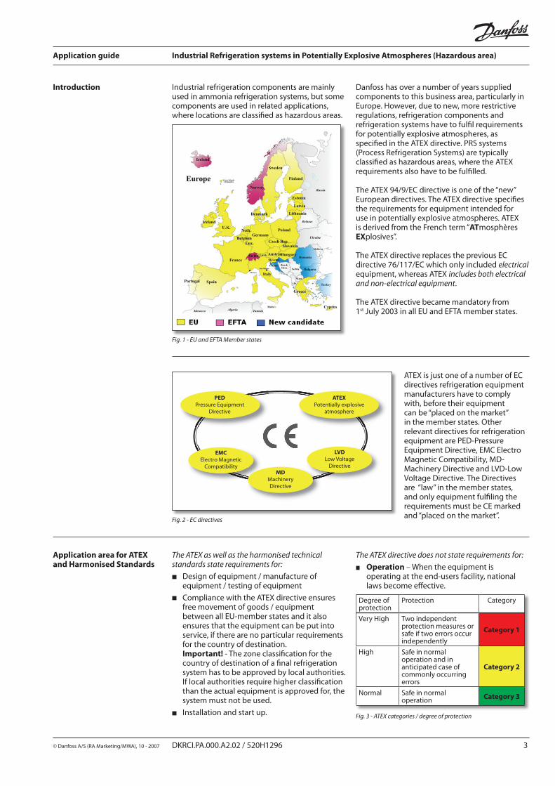
Introduction Industrial refrigeration components are mainly used in ammonia refrigeration systems, but some components are used in related applications, where locations are classified as hazardous areas.
Danfoss has over a number of years supplied components to this business area, particularly in Europe. However, due to new, more restrictive regulations, refrigeration components and refrigeration systems have to fulfil requirements for potentially explosive atmospheres, as specified in the ATEX directive. PRS systems (Process Refrigeration Systems) are typically classified as hazardous areas, where the ATEX requirements also have to be fulfilled. The ATEX 94/9/EC directive is one of the “new” European directives. The ATEX directive specifies the requirements for equipment intended for use in potentially explosive atmospheres. ATEX is derived from the French term “ATmosphères EXplosives”.
The ATEX directive replaces the previous EC directive 76/117/EC which only included electrical equipment, whereas ATEX includes both electrical and non-electrical equipment.
The ATEX directive became mandatory from 1st July 2003 in all EU and EFTA member states.
Fig. 1 - EU and EFTA Member states
ATEX is just one of a number of EC directives refrigeration equipment manufacturers have to comply with, before their equipment can be “placed on the market” in the member states. Other relevant directives for refrigeration equipment are PED-Pressure Equipment Directive, EMC Electro Magnetic Compatibility, MD-Machinery Directive and LVD-Low Voltage Directive. The Directives are “law” in the member states, and only equipment fulfiling the requirements must be CE marked and “placed on the market”.
Fig. 2 - EC directives
ATEXPotentially explosive
atmosphere
PEDPressure Equipment
Directive
EMCElectro Magnetic
Compatibility
LVDLow Voltage
DirectiveMD
MachineryDirective
Application area for ATEX and Harmonised Standards
The ATEX as well as the harmonised technical standards state requirements for:
Design of equipment / manufacture of equipment / testing of equipment
Compliance with the ATEX directive ensures free movement of goods / equipment between all EU-member states and it also ensures that the equipment can be put into service, if there are no particular requirements for the country of destination. Important! - The zone classification for the country of destination of a final refrigeration system has to be approved by local authorities. If local authorities require higher classification than the actual equipment is approved for, the system must not be used.
Installation and start up.
The ATEX directive does not state requirements for:
Operation – When the equipment is operating at the end-users facility, national laws become effective.
Degree of protection
Protection Category
Very High Two independent protection measures or safe if two errors occur independently
Category 1
High Safe in normal operation and in anticipated case of commonly occurring errors
Category 2
Normal Safe in normal operation Category 3
Fig. 3 - ATEX categories / degree of protection
Application guide Industrial Refrigeration systems in Potentially Explosive Atmospheres (Hazardous area)
4 DKRCI.PA.000.A2.02 / 520H1296 © Danfoss A/S (RA Marketing/MWA), 10 - 2007
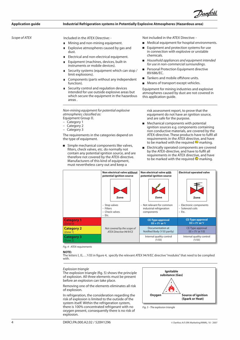
Included in the ATEX Directive: -Mining and non-mining equipment.Explosive atmospheres caused by gas and dust.Electrical and non-electrical equipment.Equipment (machines, devices, built-in instruments or mobile devices).Security systems (equipment which can stop / limit explosions). Components (parts without any independent function). Security control and regulation devices intended for use outside explosive areas but which secure the equipment in the hazardous areas .
Scope of ATEX Not included in the ATEX Directive: -Medical equipment for hospital environments.Equipment and protection systems for use in connection with explosive or unstable chemicals.Household appliances and equipment intended for use in non-commercial surroundings.Personal Protection Equipment directive 89/686/EC.Tankers and mobile offshore units.Means of transport except vehicles.
Equipment for mining industries and explosive atmospheres caused by dust are not covered in this application guide.
Non-mining equipment for potential explosive atmospheres; classified as:Equipment Group II. – Category 1 – Category 2 – Category 3
The requirements in the categories depend on the type of equipment.
Simple mechanical components like valves, filters, check valves, etc. do normally not contain any potential ignition source, and are therefore not covered by the ATEX-directive. Manufacturers of this kind of equipment, must nevertheless carry out and keep a
Non electrical valve without potential ignition source
Non electrical valve with potential ignition source
Electrical operated valve
Zone Zone Zone
– Stop valves– Filters– Check valves– Etc.
– Not relevant for common industrial refrigeration components
– Electronic components– Solenoid coils– Etc.
Category 1(Zone 0)
Not covered by the scope of ATEX Directive 94/9/CE
CE-Type approvalIII + IV or V
CE-Type approvalIII + IV or V
Category 2(Zone 1)
Documentation at Notified Body (VIII partly)
CE-Type approvalIII + IV or VII
Category 3(Zone 2)
Internal quality control(VIII)
Internal quality control(VIII)
Fig. 4 - ATEX-requirements
Explosion triangleThe explosion triangle (fig. 5) shows the principle of explosion. All three elements must be present before an explosion can take place.
Removing one of the elements eliminates all risk of explosion.
In refrigeration, the consideration regarding the risk of explosion is limited to the outside of the system itself. Within the refrigeration system, there is 100% concentrated refrigerant with no oxygen present, consequently there is no risk of explosion.
Fig. 5 - The explosion triangle
NOTE: The letters I, II,….VIII in figure 4, specify the relevant ATEX 94/9/EC directive “modules” that need to be complied with.
risk assessment report, to prove that the equipment do not have an ignition source, and are safe for the purpose.Mechanical components with potential ignition sources e.g. components containing non conductive materials, are covered by the ATEX-directive. These products have to fulfil all requirements in the ATEX directive, and have to be marked with the required marking.Electrically operated components are covered by the ATEX-directive, and have to fulfil all requirements in the ATEX directive, and have to be marked with the required marking.
Application guide Industrial Refrigeration systems in Potentially Explosive Atmospheres (Hazardous area)
© Danfoss A/S (RA Marketing/MWA), 10 - 2007 DKRCI.PA.000.A2.02 / 520H1296 5
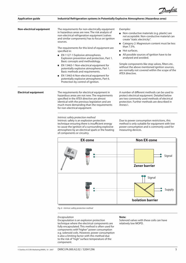
Non-electrical equipment The requirements for non-electrically equipment in hazardous areas are new. The risk analysis of non-electrical refrigeration equipment (valves and similar components) has to focus on ignition sources.
The requirements for this kind of equipment are specified in:
EN 1127-1 Explosive atmospheres. Explosion prevention and protection, Part 1. Basic concepts and methodology.
EN 13463-1 Non-electrical equipment for potentially explosive atmospheres, Part 1. Basic methods and requirements.
EN 13463-6 Non-electrical equipment for potentially explosive atmospheres, Part 6. Protection by control of ignition.
Examples:
Non-conductive materials (e.g. plastic) are not acceptable. Non-conductive material can create “static electricity”.
Category 2: Magnesium content must be less than 7.5%.
Hot surfaces.
All possible sources of ignition have to be analysed and avoided.
Simple components like stop valves, filters etc. without the above mentioned ignition sources, are normally not covered within the scope of the ATEX directive.
Electrical equipment The requirements for electrical equipment in hazardous areas are not new. The requirements specified in the ATEX directive are almost identical with the previous legislation and are much more demanding than the requirements for non-electrical equipment.
Intrinsic safety protection methodIntrinsic safety is an explosion protection technique ensuring there is insufficient energy to cause the ignition of a surrounding explosive atmosphere by an electrical spark or the heating of components or circuitry.
EX-zone Non EX-zone
EncapsulationEncapsulation is an explosion protection technique where the electrical components are fully encapsulated. This method is often used for components with“higher” power consumption e.g. solenoid coils. However, power consumption is also a limiting factor with this method due to the risk of “high” surface temperature of the component.
Fig. 6 - Intrinsic safety protection method
Note: Solenoid valves with these coils can have relatively low MOPD.
A number of different methods can be used to protect electrical equipment. Detailed below are two commonly used methods of electrical protection. Further methods are described in Annex I.
Due to power consumption restrictions, this method is only suitable for equipment with low power consumption and is commonly used for measuring devices.
Application guide Industrial Refrigeration systems in Potentially Explosive Atmospheres (Hazardous area)
6 DKRCI.PA.000.A2.02 / 520H1296 © Danfoss A/S (RA Marketing/MWA), 10 - 2007
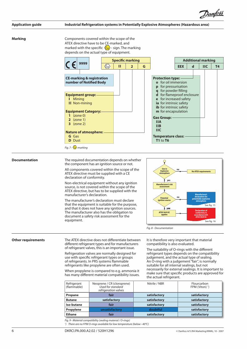
Marking Components covered within the scope of the ATEX directive have to be CE-marked, and marked with the specific - sign. The marking depends on the actual type of equipment.
9999Specific marking Additional marking
II 2 G EEX d IIC T4
CE-marking & registration number of Notified Body
Equipment group: I Mining II Non-mining
Equipment Category: 1 (zone 0) 2 (zone 1) 3 (zone 2)
Nature of atmosphere: G Gas D Dust
Protection type: o for oil immersion p for pressurisation q for powder filling d for flameproof enclosure e for increased safety ia for intrinsic safety ib for intrinsic safety m for encapsulation
Gas Group: IIA IIB IIC
Temperature class: T1 to T6
Fig. 7 - -marking
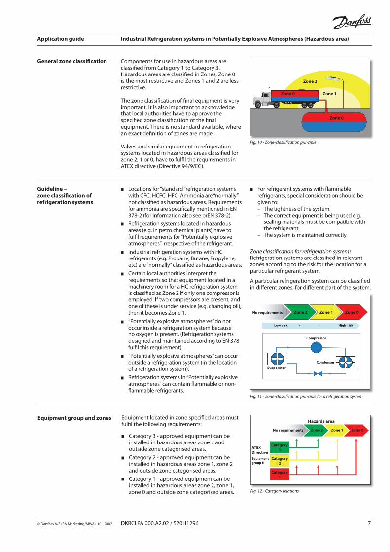
Documentation The required documentation depends on whether the component has an ignition source or not. All components covered within the scope of theATEX directive must be supplied with a CE declaration of conformity.
Non-electrical equipment without any ignition source, is not covered within the scope of the ATEX directive, but has to be supplied with the manufacturer’s declaration.
The manufacturer’s declaration must declare that the equipment is suitable for the purpose, and that it does not have any ignition sources. The manufacturer also has the obligation to document a safety risk assessment for the equipment.
Use in Explosive
atmosphereNo ATEX requirements
Manufacturer’s risk assessment
Potential ignition source
ATEX 94/9 EC applies
Manufacture's declaration for
potentially explosive atmosphere
Declaration of conformity in
accordance with ATEX 94/9 EC
yesyes
Use inExplosive
atmosphere
Manufacturer’s riskassessment
Potentialignition source
ATEX 94/9 ECapplies
No ATEX requirements
Manufacture’s declaration for
potentially explosiveatmosphere
Declaration ofconformity in
accordance with ATEX 94/9 EC
no
yes
no
Other requirements The ATEX directive does not differentiate between different refrigerant types and for manufacturers of refrigerant valves, this is an important issue.
Refrigeration valves are normally designed for use with specific refrigerant types or groups of refrigerants. In PRS systems flammable refrigerants like propylene are often used.
When propylene is compared to e.g. ammonia it has many different material compatibility issues.
It is therefore very important that material compatibility is also evaluated.
The suitability of O-rings with the different refrigerant types depends on the compatibility judgement, and the actual type of sealing.An O-ring with a judgement “fair”, is normally suitable for all internal sealings, but not necessarily for external sealings. It is important to make sure that specific products are approved for the actual refrigerant.
Refrigerant (flammable)
Neoprene / CR (cloroprene) Used for standard
refrigeration valves
Nitrile / NBR FlourcarbonFPM (Viton) 1)
Propane fair satisfactory satisfactory
Butane satisfactory satisfactory satisfactory
Iso-butane fair satisfactory satisfactory
Propylene unsatisfactory doubtful satisfactory
Ethane fair satisfactory satisfactory
Fig. 8 - Documentation
Fig. 9 - Material compatibility (sealing material / O-rings)1) There are no FPM O-rings available for low temperature (below –40°C)
See fig. 15
See fig. 16
Application guide Industrial Refrigeration systems in Potentially Explosive Atmospheres (Hazardous area)
© Danfoss A/S (RA Marketing/MWA), 10 - 2007 DKRCI.PA.000.A2.02 / 520H1296 7
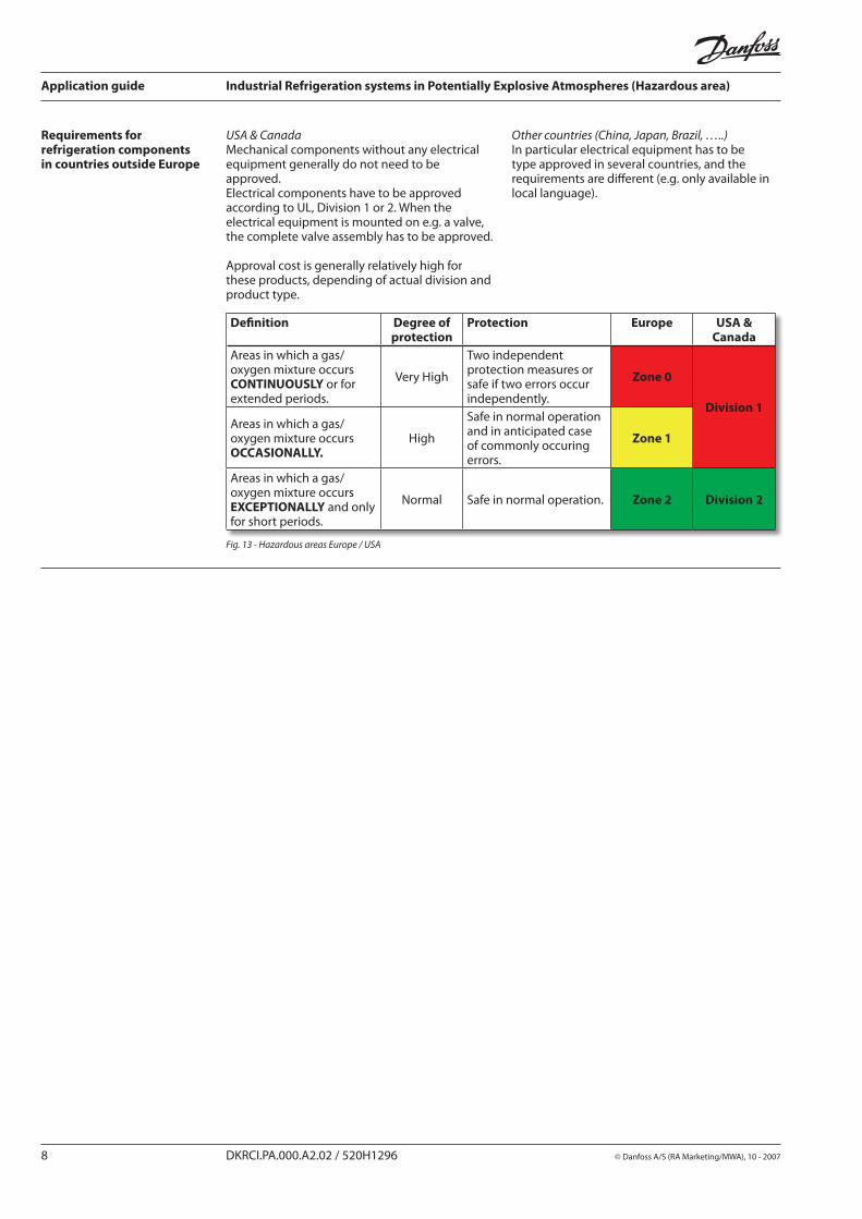
General zone classification Components for use in hazardous areas are classified from Category 1 to Category 3. Hazardous areas are classified in Zones; Zone 0 is the most restrictive and Zones 1 and 2 are less restrictive.
The zone classification of final equipment is very important. It is also important to acknowledge that local authorities have to approve the specified zone classification of the final equipment. There is no standard available, where an exact definition of zones are made.
Valves and similar equipment in refrigeration systems located in hazardous areas classified for zone 2, 1 or 0, have to fulfil the requirements in ATEX directive (Directive 94/9/EC).
Guideline – zone classification of refrigeration systems
Locations for “standard “refrigeration systems with CFC, HCFC, HFC, Ammonia are “normally” not classified as hazardous areas. Requirements for ammonia are specifically mentioned in EN 378-2 (for information also see prEN 378-2).
Refrigeration systems located in hazardous areas (e.g. in petro chemical plants) have to fulfil requirements for “Potentially explosive atmospheres” irrespective of the refrigerant.
Industrial refrigeration systems with HC refrigerants (e.g. Propane, Butane, Propylene, etc) are “normally” classified as hazardous areas.
Certain local authorities interpret the requirements so that equipment located in a machinery room for a HC refrigeration system is classified as Zone 2 if only one compressor is employed. If two compressors are present, and one of these is under service (e.g. changing oil), then it becomes Zone 1.
“Potentially explosive atmospheres” do not occur inside a refrigeration system because no oxygen is present. (Refrigeration systems designed and maintained according to EN 378 fulfil this requirement).
“Potentially explosive atmospheres” can occur outside a refrigeration system (in the location of a refrigeration system).
Refrigeration systems in “Potentially explosive atmospheres” can contain flammable or non-flammable refrigerants.
Zone classification, general
Zone 0
Zone 2
Zone 1
Zone 0
Zone 0
Zone 2
Zone 1
Zone 0
Zone classification for refrigeration systemsRefrigeration systems are classified in relevant zones according to the risk for the location for a particular refrigerant system.
A particular refrigeration system can be classified in different zones, for different part of the system.
Fig. 10 - Zone-classification principle
Zone 0Zone 1Zone 2No requirements
Low risk - - High risk
Evaporator
Compressor
Condenser
Fig. 11 - Zone-classification principle for a refrigeration system
Equipment group and zones Equipment located in zone specified areas must fulfil the following requirements:
Category 3 - approved equipment can be installed in hazardous areas zone 2 and outside zone categorised areas.
Category 2 - approved equipment can be installed in hazardous areas zone 1, zone 2 and outside zone categorised areas.
Category 1 - approved equipment can be installed in hazardous areas zone 2, zone 1, zone 0 and outside zone categorised areas.
Zone 0Zone 1Zone 2No requirements
Hazards area
Catagory3
Catagory2
Catagory1
ATEX Directive
Equipmentgroup II
Fig. 12 - Category relations
For refrigerant systems with flammable refrigerants, special consideration should be given to: – The tightness of the system. – The correct equipment is being used e.g. sealing materials must be compatible with the refrigerant. – The system is maintained correctly.
Application guide Industrial Refrigeration systems in Potentially Explosive Atmospheres (Hazardous area)
8 DKRCI.PA.000.A2.02 / 520H1296 © Danfoss A/S (RA Marketing/MWA), 10 - 2007
Requirements for refrigeration components in countries outside Europe
USA & CanadaMechanical components without any electrical equipment generally do not need to be approved.Electrical components have to be approved according to UL, Division 1 or 2. When the electrical equipment is mounted on e.g. a valve, the complete valve assembly has to be approved. Approval cost is generally relatively high for these products, depending of actual division and product type.
Other countries (China, Japan, Brazil, …..)In particular electrical equipment has to be type approved in several countries, and the requirements are different (e.g. only available in local language).
Definition Degree of protection
Protection Europe USA & Canada
Areas in which a gas/oxygen mixture occurs CONTINUOUSLY or for extended periods.
Very High
Two independent protection measures or safe if two errors occur independently.
Zone 0
Division 1Areas in which a gas/oxygen mixture occurs OCCASIONALLY.
High
Safe in normal operation and in anticipated case of commonly occuring errors.
Zone 1
Areas in which a gas/oxygen mixture occurs EXCEPTIONALLY and only for short periods.
Normal Safe in normal operation. Zone 2 Division 2
Fig. 13 - Hazardous areas Europe / USA
Application guide Industrial Refrigeration systems in Potentially Explosive Atmospheres (Hazardous area)
© Danfoss A/S (RA Marketing/MWA), 10 - 2007 DKRCI.PA.000.A2.02 / 520H1296 9
Solenoid coils type BP II 2 G EEx m II T4
The coils are suitable for use in installations located in potentially explosive atmospheres.
l ATEX Category 2 (Zone 1). l Grade of enclosure: IP 67.l Supplied with 3 m moulded-in 3-core cable.l 16 W dc.
NOTE 1: The coil has reduced MOPD (MOPD~8 bar depending of actual valve type).
NOTE 2: The supply must be secured against a too high power consumption in case of a short circuit.
Literature No.: DKACV.PD.600.A
Categ
ory 2 – Zo
ne1
Solenoid coils type “refrigeration” II 3 G EEx nA II T3
The coils are suitable for use in installations located in potentially explosive atmospheres.
l ATEX Category 3 (Zone 2). l Grade of enclosure: IP 67.l Supplied with 1 m moulded-in 3-core cable or terminal. 1- 20 W dc & ac
NOTE: The supply must be secured against a too high power consumption in case of a short circuit.
Literature No.: RD3JE
Categ
ory 3 – Zo
ne 2
Pressure Control type MP 55E II 3 G EEx nL IIC T6
The differential pressure controls are suitable for use in installations located in potentially explosive atmospheres.
l ATEX Category 3 (Zone 2).l Grade of enclosure: IP 20.l Max working pressure PS = 17 bar.l ATEX design o Gold contactors. o Stainless steel bellow with restricted movement. o Soldering connection.
NOTE: Contact loads - Must be used with reliable means of limiting the voltage and current to prevent sparks between the contact surfaces. This could be zener diodes or Ex barriers.
Literature No.: RD5CB
Categ
ory 3 – Zo
ne 2
Pressure Control type KPE II 3 G EEx nL IIC T6
The pressure controls are suitable for use in installations located in potentially explosive atmospheres.
l ATEX Category 3 (Zone 2). l Grade of enclosure: IP 30 or IP 40l Max working pressure: KP 1E: PS = 8 bar. KP 7E: PS = 32 bar.l ATEX design o Gold contactors. o Stainless steel bellow with restricted movement. o Soldering connection.
NOTE: Contact loads - Must be used with reliable means of limiting the voltage and current to prevent sparks between the contact surfaces. This could be zener diodes or Ex barriers.
Literature No.: RD5AC
Categ
ory 3 – Zo
ne 2
Danfoss solenoid coils, pressure controls and gas detectors suitable for use in installations located in potentially explosive atmospheres
Application guide Industrial Refrigeration systems in Potentially Explosive Atmospheres (Hazardous area)
10 DKRCI.PA.000.A2.02 / 520H1296 © Danfoss A/S (RA Marketing/MWA), 10 - 2007
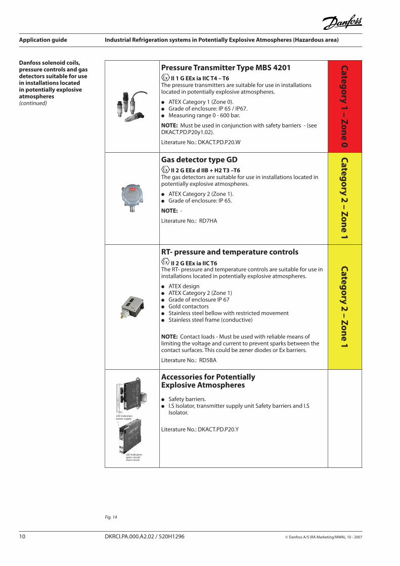
Pressure Transmitter Type MBS 4201 II 1 G EEx ia IIC T4 – T6
The pressure transmitters are suitable for use in installations located in potentially explosive atmospheres.
l ATEX Category 1 (Zone 0). l Grade of enclosure: IP 65 / IP67.l Measuring range 0 - 600 bar.
NOTE: Must be used in conjunction with safety barriers - (see DKACT.PD.P20y1.02).
Literature No.: DKACT.PD.P20.W
Categ
ory 1 – Zo
ne 0
Gas detector type GD II 2 G EEx d IIB + H2 T3 –T6
The gas detectors are suitable for use in installations located in potentially explosive atmospheres.
l ATEX Category 2 (Zone 1). l Grade of enclosure: IP 65.
NOTE: -
Literature No.: RD7HA
Categ
ory 2 – Zo
ne 1
RT- pressure and temperature controls II 2 G EEx ia IIC T6
The RT- pressure and temperature controls are suitable for use in installations located in potentially explosive atmospheres.
l ATEX designl ATEX Category 2 (Zone 1) l Grade of enclosure IP 67 l Gold contactorsl Stainless steel bellow with restricted movementl Stainless steel frame (conductive)
NOTE: Contact loads - Must be used with reliable means of limiting the voltage and current to prevent sparks between the contact surfaces. This could be zener diodes or Ex barriers.
Literature No.: RD5BA
Categ
ory 2 – Zo
ne 1
LED indicationpower supply
LED indication open-circuit/short-circuit
Accessories for Potentially Explosive Atmospheres
l Safety barriers.l I.S Isolator, transmitter supply unit Safety barriers and I.S Isolator.
Literature No.: DKACT.PD.P20.Y
Danfoss solenoid coils, pressure controls and gas detectors suitable for use in installations located in potentially explosive atmospheres (continued)
Fig. 14
Application guide Industrial Refrigeration systems in Potentially Explosive Atmospheres (Hazardous area)
© Danfoss A/S (RA Marketing/MWA), 10 - 2007 DKRCI.PA.000.A2.02 / 520H1296 11
Declaration of conformity in accordance with ATEX 94/9 EC
Manufacturer’s declaration for potentially explosive atmospheres
Danfoss Industrial Refrigeration has a quality and environmental management system that is certified in accordance with international standards ISO 9001 and ISO 14001. Our products comply with the requirements of the Pressure Equipment Directive 97/23/EC and are approved by TÜV Nord (0045)
Manufacturer’s Declaration to the European Directive ATEX 94/9/CE
Group D Component with special sealing material for HC-refrigerants ( Propane, Butane, Iso-butane and Propylene)
and - can be mounted with electrically pilots / equipment and - have no ignition sources
Main Valves (control valves) ICS 3E Modulating liquid level regulators PMFLE Pilots for ICS Valves CVP-HPE Pilots for ICS Valves EVME
For the above listed valves a hazard analysis to the directive ATEX 94/9/EC has been carried out with the following result:
This non-electrical equipment holds no potential ignition source at normal usage. The listed valves are not covered by the scope of ATEX Directive 94/9/EC. The valves my be used in the following EX range:
Category 2 (Zone 1) and Category 3 (Zone 2)
IMPORTANT:The above-mentioned valves are not identically to standard refrigeration valves.The valves are equipped with special o-rings compatible with the specified refrigerants.The valves have a reduced temperature range.
Note 1: Valves used for the above condition has to installed and maintained according to the requirements in EN 378.
Note 2:Electronic / Mechanical actuators / pilots used to operate the above-mentioned equipment, has to undergo a separate conformity assessment.
Reference to standards and directives:
EN 13453-1 EN 13453-5 EN 378 ATEX 94/9/EC
14/04/2005 Danfoss Industrial Refrigeration A/S
Fig. 15
Fig. 16
Application guide Industrial Refrigeration systems in Potentially Explosive Atmospheres (Hazardous area)
12 DKRCI.PA.000.A2.02 / 520H1296 © Danfoss A/S (RA Marketing/MWA), 10 - 2007
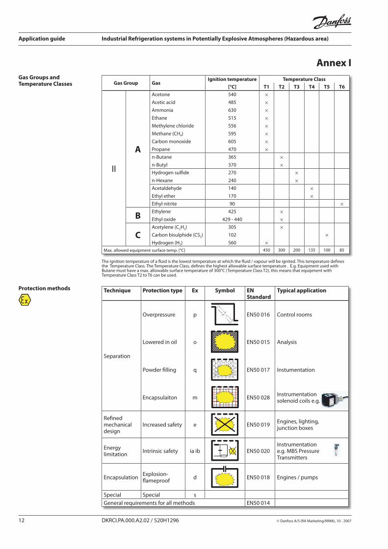
Gas Groups and Temperature Classes Gas Group Gas
Ignition temperature Temperature Class
[°C] T1 T2 T3 T4 T5 T6
II
A
Acetone
Acetic acid
Ammonia
Ethane
Methylene chloride
Methane (CH4)
Carbon monoxide
Propane
540
485
630
515
556
595
605
470
××××××××
n-Butane
n-Butyl
365
370
××
Hydrogen sulfide
n-Hexane
270
240
××
Acetaldehyde
Ethyl ether
140
170
××
Ethyl nitrite 90 ×
BEthylene
Ethyl oxide
425
429 - 440
××
CAcetylene (C2H2)
Carbon bisulphide (CS2)
Hydrogen (H2)
305
102
560 ×
××
Max. allowed equipment surface temp. [°C] 450 300 200 135 100 85
Protection methods Technique Protection type Ex Symbol EN Standard
Typical application
Separation
Overpressure p EN50 016 Control rooms
Lowered in oil o EN50 015 Analysis
Powder filling q EN50 017 Instumentation
Encapsulaiton m EN50 028 Instrumentation solenoid coils e.g.
Refined mechanical design
Increased safety e EN50 019 Engines, lighting, junction boxes
Energy limitation Intrinsic safety ia ib EN50 020
Instrumentatione.g. MBS Pressure Transmitters
Encapsulation Explosion-flameproof d EN50 018 Engines / pumps
Special Special sGeneral requirements for all methods EN50 014
Annex I
The ignition temperature of a fluid is the lowest temperature at which the fluid / vapour will be ignited. This temperature defines the Temperature Class. The Temperature Class, defines the highest allowable surface temperature . E.g. Equipment used with Butane must have a max. allowable surface temperature of 300°C (Temperature Class T2), this means that equipment with Temperature Class T2 to T6 can be used.
Application guide Industrial Refrigeration systems in Potentially Explosive Atmospheres (Hazardous area)
© Danfoss A/S (RA Marketing/MWA), 10 - 2007 DKRCI.PA.000.A2.02 / 520H1296 13
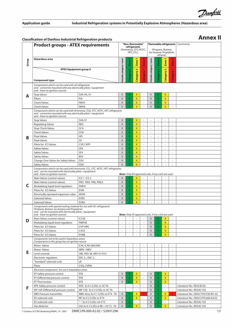
Annex IIClassification of Danfoss Industrial Refrigeration products
Gro
up
Product groups - ATEX requirements “Non-flammable” refrigerants
(Ammonia, CFC,HCFC, HFC,CO2)
Flammable refrigerants
(Propane, Butane, Iso-butane, Propylene,
ethane)
Comments
Hazardous area
Out
sid
e ca
tag
ory
/ zon
e
Zon
e 2
Zon
e 1
Zon
e 0
Out
sid
e ca
tag
ory
/ zon
e
Zon
e 2
Zon
e 1
Zon
e 0
ATEX Equipment group II
Component type Cat
ego
ry 3
Cat
ego
ry 2
Cat
ego
ry 1
Cat
ego
ry 3
Cat
ego
ry 2
Cat
ego
ry 1
A
Components which can be used with all refrigerantsand - cannot be mounted with any electrically pilots / equipmentand - have no ignition sources
Stop Valves SVA-HS, X1 X X X - X X X -
Filters FIA X X X - X X X -
Check Valves NRVS X X X - X X X -
Check Valves NRVA X X X - X X X -
B
Components which can be used with Ammonia, CO2, CFC, HCFC, HFC refrigerantsand - cannot be mounted with any electrically pilots / equipmentand - have no ignition sources
Stop Valves SVA-ST X X X - - - - -
Regulating Valves REG X X X - - - - -
Stop Check Valves SCA X X X - - - - -
Check Valves CHV X X X - - - - -
Float Valves HFI X X X - - - - -
Float Valves SV X X X - - - - -
Pilots for ICS Valves CVP, CVPP X X X - - - - -
Safety Valves SFA X X X - - - - -
Safety Valves SFV X X X - - - - -
Safety Valves BSV X X X - - - - -
Change Over Valves for Safety Valves DSV X X X - - - - -
Safety Valves POV X X X - - - - -
C
Components which can be used with Ammonia, CO2, CFC, HCFC, HFC refrigerantsand - can be mounted with electrically pilots / equipmentand - have no ignition sources Note: Only EX approved coils, if any coils are used
Main Valves (control valves) ICS 1 ICS 3 X X X - - - - -
Main Valves (control valves) PM1 PM3 PML PMLX X X X - - - - -
Modulating liquid level regulators PMFH X X X - - - - -
Pilots for ICS Valves EVM X X X - - - - -
Electrically operated expansion valve AKVA X X X - - - - -
Solenoid Valves EVRS X X X - - - - -
Solenoid Valves EVRA X X X - - - - -
D
Components with special sealing material for use with HC-refrigerants (Probane, Butane, Iso-butane and Propylene)and - can be mounted with electrically pilots / equipmentand - have no ignition sources Note: Only EX approved coils, if any coils are used
Main Valves (control valves) ICS3E - - - - X X X -
Modulating liquid level regulators PMFHE - - - - X X X -
Pilots for ICS Valves CVP-HPE - - - - X X X -
Pilots for ICS Valves CVCE - - - - X X X -
Pilots for ICS Valves EVME - - - - X X X -
E
Components not to be used in hazardous areasComponents in this group has an ignition source
Motor Valves ICM, ICAD 600/900 - - - - - - - -
Motor Valves MRV / MEV - - - - - - - -
Level controls 38E, AKS 38, AKS 41/41U - - - - - - - -
Electronic regulators EKC 2.., EKC 3.. - - - - - - - -
“Standard” solenoid coils all - - - - - - - -
Pilots CVQ, CVPM - - - - - - - -
F
Electrical components for use in hazardous areas
RT-Safety pressure control RTE X X X - X X X -
RT-Differential pressure control RTE X X X - X X X -
RT-Thermostats RTE X X X - X X X -
KPE-Safety pressure control KPE; Ex II 3 G EEx nL IIC T6 - - - - X X - - Literature No.: RD5CB102
MP 55E-Differential pressure control MP 55E; Ex II 3 G EEx nL IIC T6 - - - - X X - - Literature No.: RD5AC103
MBS Pressure transmitter MBS 42xx; Ex II 1 G EEx ia II T4 - T6 X X X X X X X X Literature No.: DKACT.PD.P20.W1.02
EX solenoid coils BP; Ex II 2 G EEx m II T4 X X X - X X X - Literature No.: DKACV.PD.600.A4.03
EX solenoid coils “ “; Ex II 3 G EEx nA II T3 X X - - X X - - Literature No.: RD5AC103
Gas detector GD; Ex II 2 G EEx d IIB + H2 T3 –T6 X X X - X X X - Literature No.: RD5AC103
Application guide Industrial Refrigeration systems in Potentially Explosive Atmospheres (Hazardous area)
14 DKRCI.PA.000.A2.02 / 520H1296 © Danfoss A/S (RA Marketing/MWA), 10 - 2007
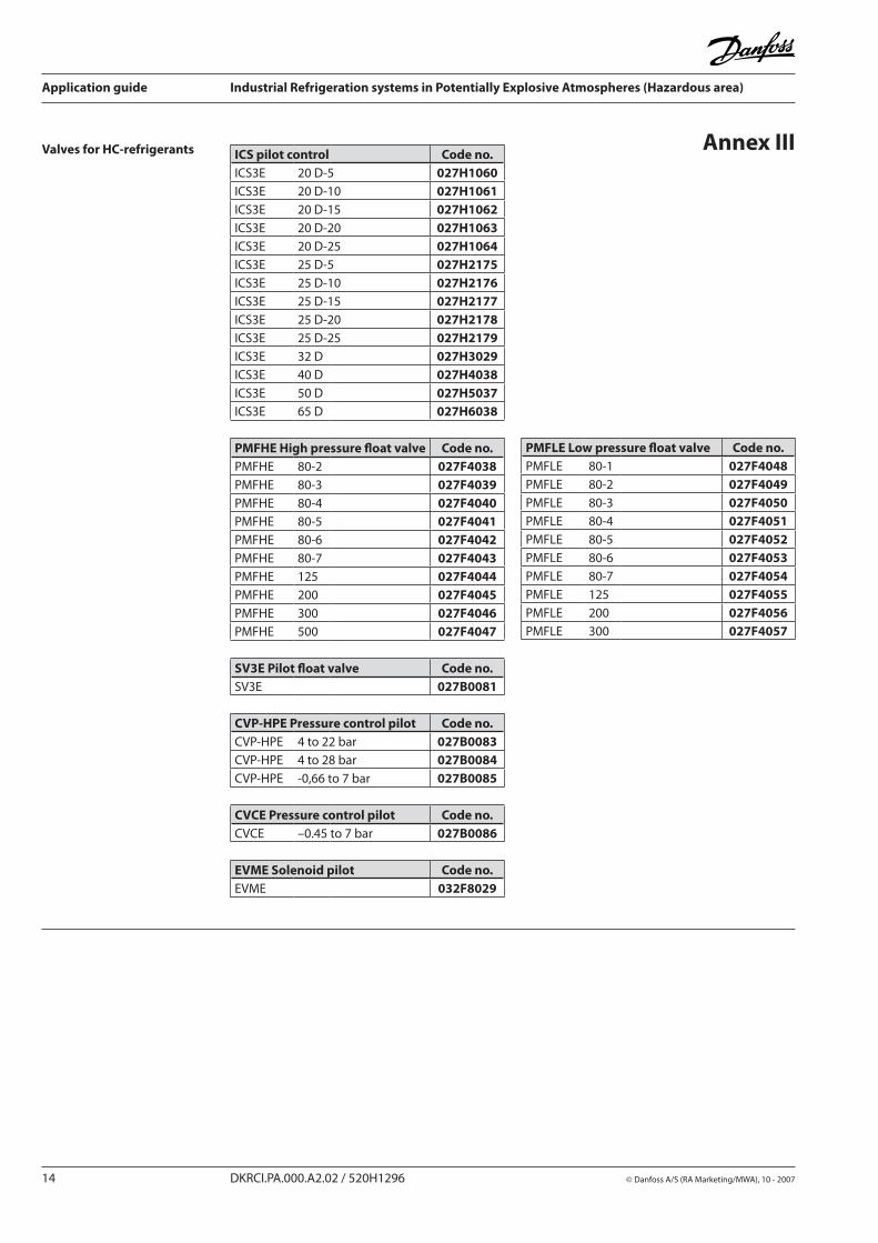
ICS pilot control Code no.ICS3E 20 D-5 027H1060ICS3E 20 D-10 027H1061ICS3E 20 D-15 027H1062ICS3E 20 D-20 027H1063ICS3E 20 D-25 027H1064ICS3E 25 D-5 027H2175ICS3E 25 D-10 027H2176ICS3E 25 D-15 027H2177ICS3E 25 D-20 027H2178ICS3E 25 D-25 027H2179ICS3E 32 D 027H3029ICS3E 40 D 027H4038ICS3E 50 D 027H5037ICS3E 65 D 027H6038
PMFHE High pressure float valve Code no.PMFHE 80-2 027F4038PMFHE 80-3 027F4039PMFHE 80-4 027F4040PMFHE 80-5 027F4041PMFHE 80-6 027F4042PMFHE 80-7 027F4043PMFHE 125 027F4044PMFHE 200 027F4045PMFHE 300 027F4046PMFHE 500 027F4047
SV3E Pilot float valve Code no.SV3E 027B0081
CVP-HPE Pressure control pilot Code no.CVP-HPE 4 to 22 bar 027B0083CVP-HPE 4 to 28 bar 027B0084CVP-HPE -0,66 to 7 bar 027B0085
CVCE Pressure control pilot Code no.CVCE –0.45 to 7 bar 027B0086
EVME Solenoid pilot Code no.EVME 032F8029
Valves for HC-refrigerants
PMFLE Low pressure float valve Code no.PMFLE 80-1 027F4048PMFLE 80-2 027F4049PMFLE 80-3 027F4050PMFLE 80-4 027F4051PMFLE 80-5 027F4052PMFLE 80-6 027F4053PMFLE 80-7 027F4054PMFLE 125 027F4055PMFLE 200 027F4056PMFLE 300 027F4057
Annex III
Application guide Industrial Refrigeration systems in Potentially Explosive Atmospheres (Hazardous area)
© Danfoss A/S (RA Marketing/MWA), 10 - 2007 DKRCI.PA.000.A2.02 / 520H1296 15
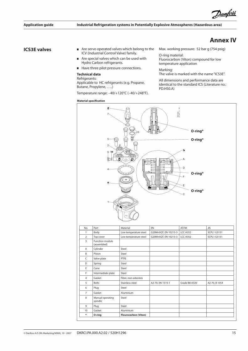
Are servo operated valves which belong to the ICV (Industrial Control Valve) family.
Are special valves which can be used with Hydro Carbon refrigerants.
Have three pilot pressure connections.
Technical data Refrigerants:Applicable to HC refrigerants (e.g. Propane, Butane, Propylene, …..)
Temperature range: –40/+120°C (–40/+248°F).
ICS3E valves Max. working pressure: 52 bar g (754 psig)
O-ring material:Fluorocarbon (Viton) compound for low temperature application
Marking:The valve is marked with the name “ICS3E”.
All dimensions and performance data are identical to the standard ICS (Literature no.: PD.HS0.A)
Material specification
No. Part Material EN ASTM JIS
1 Body Low temperature steel G20Mn5QT, EN 10213-3 LCC A352 SCPL1 G5151
2 Top cover Low temperature steel G20Mn5QT, EN 10213-3 LCC A352 SCPL1 G5151
3 Function module(assembled)
A Cylinder Steel
B Piston Steel
C Valve plate PTFE
D Spring Steel
E Cone Steel
F Intermediate plate Steel
4 Gasket Fibre, non-asbestos
5 Bolts Stainless steel A2-70, EN 1515-1 Grade B8 A320 A2-70, B 1054
6 Plug Steel
7 Gasket Aluminium
8 Manual operating spindle
Steel
9 Plug Steel
10 Gasket Aluminium
* O-ring Flourocarbon (Viton)
O-ring*
O-ring*
O-ring*
O-ring*
Annex IV
Application guide Industrial Refrigeration systems in Potentially Explosive Atmospheres (Hazardous area)
16 DKRCI.PA.000.A2.02 / 520H1296 © Danfoss A/S (RA Marketing/MWA), 10 - 2007
Are modulating servo-controlled main expansion valves, controlled by pilot float valve type SV3E.
Are special valves which can be used with Hydro Carbon refrigerants.
Have one pilot pressure connection.
Technical data Refrigerants:Applicable to HC refrigerants (e.g. Propane, Butane, Propylene, …..)
PMFHE or PMFLE valves
Temperature range: –40/+120°C (–40/+248°F).
Max. working pressure: 28 bar g (406 psig)
O-ring material:Fluorocarbon (Viton) compound for low temperature application
Marking:The valve is marked with the name “PMFHE” or “PMFLE”.
All dimensions and performance data are identical to the standard PMFH or PMFL (Literature no.: RD2CB).
No. Part Material DIN/EN ISO ASTM
2 Gasket between body and flange
Non-metalNon-asbestos
3 Bolts for flange Stainless steel A2-70 A2-70 Type 308
4 Flange PM 5 - 65 Steel RSt. 37-2, 10025 Fe360 B, 630 Grade C, A 283
6 Plug Steel 9SMn281651
Type 2R683/9
1213SAE J 403
10 Valve spindle Steel 9SMn281651
Type 2R683/9
1213SAE J 403
12 Valve seat Teflon [PTFE]
19 Valve body Low temperature cast iron (spherical)
EN-GJS-400-18-LTEN-1693
20 Bottom cover Low temperature cast iron (spherical)
EN-GJS-400-18-LTEN-1693
23 Spring Steel
24 Servo piston Cast iron GG-25 Grade 250 Class 40B
30 Cover Low temperature cast iron (spherical)
EN-GJS-400-18-LTEN-1693
31 Trottle cone Steel 9SMn281651
Type 2R683/9
1213SAE J 403
32 Gasket between body and bottom cover
Non-metalNon-asbestos
34 Bolts for top and bottom cover
Stainless steel A2-70 A2-70 Type 308
41 Gasket Non-metalNon-asbestos
43 Spring Steel
53 Spindle cap Steel 9SMn281651
Type 2R683/9
1213SAE J 403
60 Setting / manual operating spindle
Steel 9SMn281651
Type 2R683/9
1213SAE J 403
73 Pilot connection Steel 9SMn281651
Type 2R683/9
1213SAE J 403
* O-ring Flourocarbon (Viton)
Material specification
O-ring*
O-ring*
O-ring*
O-ring*
PMFHE PMFLE
Application guide Industrial Refrigeration systems in Potentially Explosive Atmospheres (Hazardous area)
© Danfoss A/S (RA Marketing/MWA), 10 - 2007 DKRCI.PA.000.A2.02 / 520H1296 17
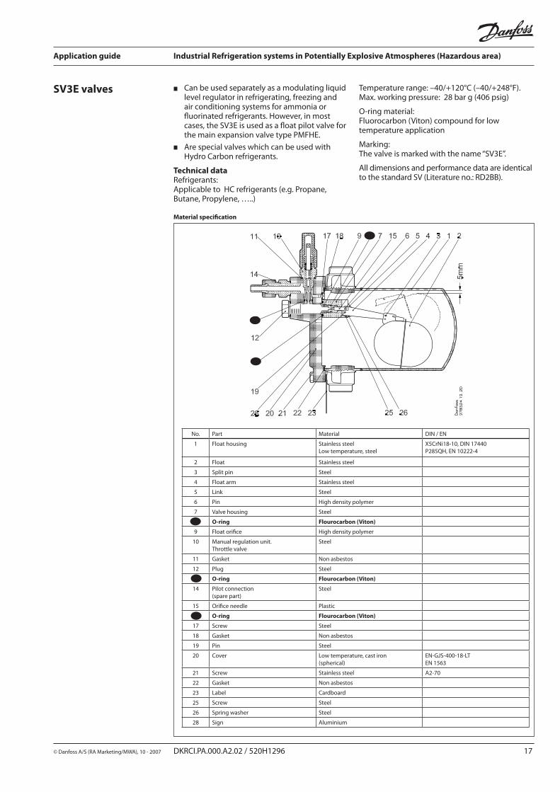
Can be used separately as a modulating liquid level regulator in refrigerating, freezing and air conditioning systems for ammonia or fluorinated refrigerants. However, in most cases, the SV3E is used as a float pilot valve for the main expansion valve type PMFHE.
Are special valves which can be used with Hydro Carbon refrigerants.
Technical data Refrigerants:Applicable to HC refrigerants (e.g. Propane, Butane, Propylene, …..)
SV3E valves Temperature range: –40/+120°C (–40/+248°F).Max. working pressure: 28 bar g (406 psig)
O-ring material:Fluorocarbon (Viton) compound for low temperature application
Marking:The valve is marked with the name “SV3E”.
All dimensions and performance data are identical to the standard SV (Literature no.: RD2BB).
No. Part Material DIN / EN
1 Float housing Stainless steel Low temperature, steel
X5CrNi18-10, DIN 17440 P285QH, EN 10222-4
2 Float Stainless steel
3 Split pin Steel
4 Float arm Stainless steel
5 Link Steel
6 Pin High density polymer
7 Valve housing Steel
8 O-ring Flourocarbon (Viton)
9 Float orifice High density polymer
10 Manual regulation unit. Throttle valve
Steel
11 Gasket Non asbestos
12 Plug Steel
13 O-ring Flourocarbon (Viton)
14 Pilot connection (spare part)
Steel
15 Orifice needle Plastic
16 O-ring Flourocarbon (Viton)
17 Screw Steel
18 Gasket Non asbestos
19 Pin Steel
20 Cover Low temperature, cast iron (spherical)
EN-GJS-400-18-LT EN 1563
21 Screw Stainless steel A2-70
22 Gasket Non asbestos
23 Label Cardboard
25 Screw Steel
26 Spring washer Steel
28 Sign Aluminium
Material specification
Application guide Industrial Refrigeration systems in Potentially Explosive Atmospheres (Hazardous area)
18 DKRCI.PA.000.A2.02 / 520H1296 © Danfoss A/S (RA Marketing/MWA), 10 - 2007
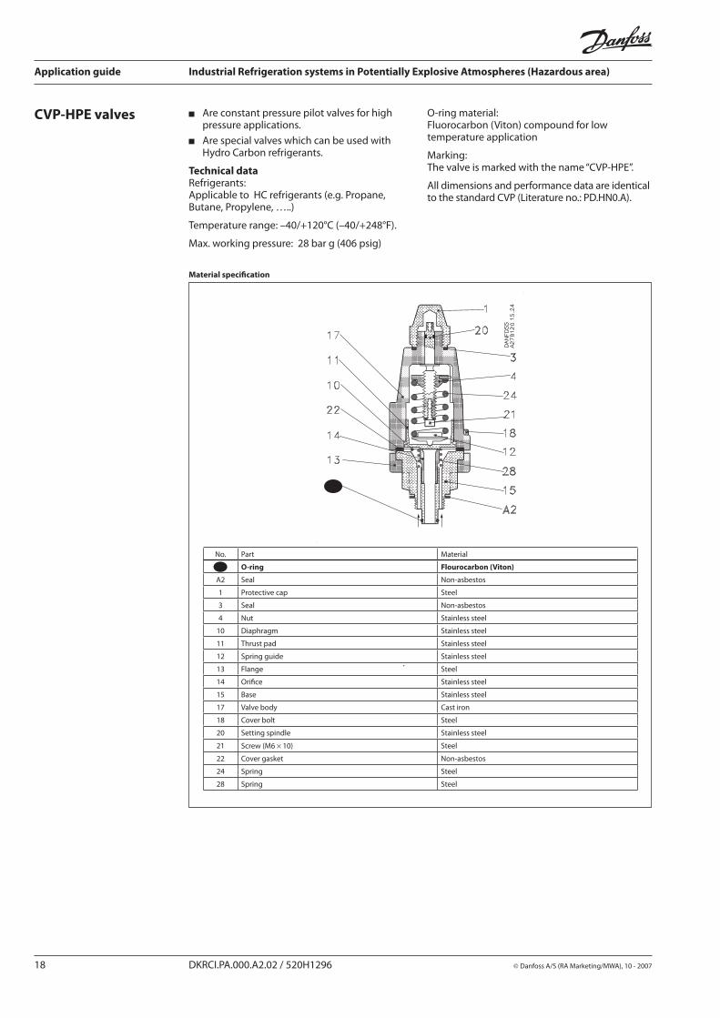
Are constant pressure pilot valves for high pressure applications.
Are special valves which can be used with Hydro Carbon refrigerants.
Technical data Refrigerants:Applicable to HC refrigerants (e.g. Propane, Butane, Propylene, …..)
Temperature range: –40/+120°C (–40/+248°F).
Max. working pressure: 28 bar g (406 psig)
CVP-HPE valves O-ring material:Fluorocarbon (Viton) compound for low temperature application
Marking:The valve is marked with the name “CVP-HPE”.
All dimensions and performance data are identical to the standard CVP (Literature no.: PD.HN0.A).
No. Part Material
A1 O-ring Flourocarbon (Viton)
A2 Seal Non-asbestos
1 Protective cap Steel
3 Seal Non-asbestos
4 Nut Stainless steel
10 Diaphragm Stainless steel
11 Thrust pad Stainless steel
12 Spring guide Stainless steel
13 Flange Steel
14 Orifice Stainless steel
15 Base Stainless steel
17 Valve body Cast iron
18 Cover bolt Steel
20 Setting spindle Stainless steel
21 Screw (M6 × 10) Steel
22 Cover gasket Non-asbestos
24 Spring Steel
28 Spring Steel
Material specification
Application guide Industrial Refrigeration systems in Potentially Explosive Atmospheres (Hazardous area)
© Danfoss A/S (RA Marketing/MWA), 10 - 2007 DKRCI.PA.000.A2.02 / 520H1296 19
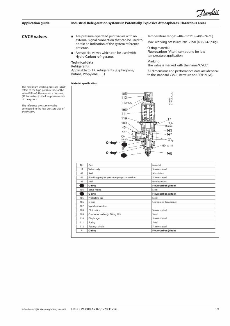
Are pressure-operated pilot valves with an external signal connection that can be used to obtain an indication of the system reference pressure.
Are special valves which can be used with Hydro Carbon refrigerants.
Technical data Refrigerants:Applicable to HC refrigerants (e.g. Propane, Butane, Propylene, …..)
CVCE valves Temperature range: –40/+120°C (–40/+248°F).
Max. working pressure: 28/17 bar (406/247 psig)
O-ring material:Fluorocarbon (Viton) compound for low temperature application
Marking:The valve is marked with the name “CVCE”.
All dimensions and performance data are identical to the standard CVC (Literature no.: PD.HN0.A).
Material specification
No. Part Material
17 Valve body Stainless steel
43 Seal Aluminium
44 Blanking plug for pressure gauge connection Stainless steel
81 Seal Non-asbestos
82 O-ring Flourocarbon (Viton)
103 Banjo fitting Steel
104 O-ring Flourocarbon (Viton)
105 Protective cap Steel
106 O-ring Cloroprene (Neoprene)
107 Signal connection
108 Pilot orifice Stainless steel
109 Connector on banjo fitting 103 Steel
110 Diaphragm Stainless steel
111 Spring Steel
112 Setting spindle Stainless steel
* O-ring Flourocarbon (Viton)
O-ring*
O-ring*
The maximum working pressure (MWP)refers to the high-pressure side of thevalve (28 bar); the reference pressure(17 bar) refers to the low-pressure sideof the system.
The reference pressure must beconnected to the low-pressure side ofthe system.
Application guide Industrial Refrigeration systems in Potentially Explosive Atmospheres (Hazardous area)
20 DKRCI.PA.000.A2.02 / 520H1296 © Danfoss A/S (RA Marketing/MWA), 10 - 2007
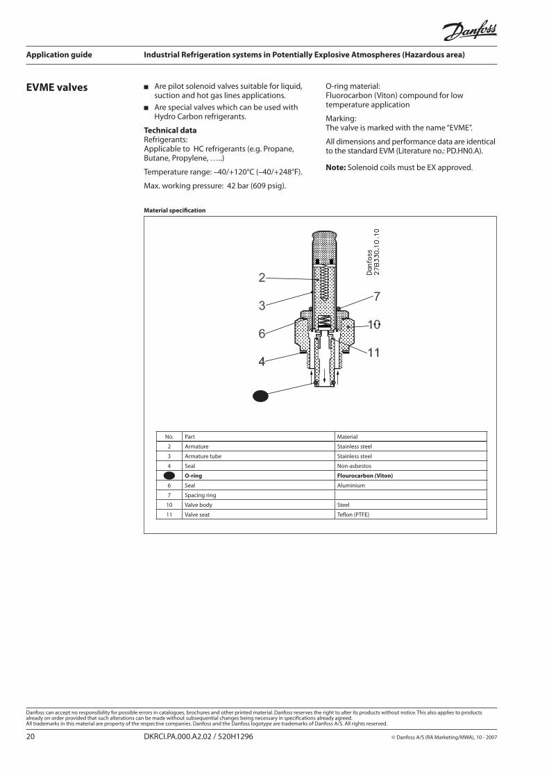
Are pilot solenoid valves suitable for liquid, suction and hot gas lines applications.
Are special valves which can be used with Hydro Carbon refrigerants.
Technical data Refrigerants:Applicable to HC refrigerants (e.g. Propane, Butane, Propylene, …..)
Temperature range: –40/+120°C (–40/+248°F).
Max. working pressure: 42 bar (609 psig).
EVME valves O-ring material:Fluorocarbon (Viton) compound for low temperature application
Marking:The valve is marked with the name “EVME”.
All dimensions and performance data are identical to the standard EVM (Literature no.: PD.HN0.A).
Note: Solenoid coils must be EX approved.
No. Part Material
2 Armature Stainless steel
3 Armature tube Stainless steel
4 Seal Non-asbestos
5 O-ring Flourocarbon (Viton)
6 Seal Aluminium
7 Spacing ring
10 Valve body Steel
11 Valve seat Teflon (PTFE)
Material specification
5