Embed Size (px)
Citation preview

User Manual
Industrial ProtocolsIndustrial ETHERNET (Gigabit-)Switch RS20/RS30/RS40, MS20/MS30, OCTOPUS, Power MICE, MACH 1000, MACH 4000
Industrial ProtocolsRelease 3.1 06/07
Technical [email protected]
The naming of copyrighted trademarks in this manual, even when not specially indicated, should not be taken to mean that these names may be considered as free in the sense of the trademark and tradename protection law and hence that they may be freely used by anyone.
© 2007 Hirschmann Automation and Control GmbH
Manuals and software are protected by copyright. All rights reserved. The copying, reproduction, translation, conversion into any electronic medium or machine scannable form is not permitted, either in whole or in part. An exception is the preparation of a backup copy of the software for your own use. For devices with embedded software, the end-user license agreement on the en-closed CD applies.
The performance features described here are binding only if they have been expressly guaran-teed in the contract. This publication has been created by Hirschmann Automation and Control GmbH according to the best of our knowledge. Hirschmann reserves the right to change the con-tents of this manual without prior notice. Hirschmann can give no guarantee in respect of the correctness or accuracy of the details in this publication.
Hirschmann can accept no responsibility for damages, resulting from the use of the network components or the associated operating software. In addition, we refer to the conditions of use specified in the license contract.
Printed in GermanyHirschmann Automation and Control GmbHStuttgarter Str. 45-5172654 NeckartenzlingenGermanyTel.: +49 1805 141538
-01-0607 – 18.7.07
Content
ContentAbout this Manual 5
Key 7
1 Industrial Protocols 9
2 EtherNet/IP 13
2.1 Integration in Control System 14
2.2 EtherNet/IP Parameters 172.2.1 Identity Objekt 172.2.2 TCP/IP Interface Object 182.2.3 Ethernet Link Object 202.2.4 Ethernet Switch Agent Object 222.2.5 I/O Data 242.2.6 Mapping of the Ethernet Link Object Instances 252.2.7 Supported services 26
3 PROFINET IO 27
3.1 Integration in Control System 293.1.1 Configuration of the Switch 293.1.2 Configuration of the PLC 30
3.2 PROFINET IO Parameters 353.2.1 Alarms 353.2.2 Record Parameters 36
A Reader´s comments 37
B Index 39
C Further support 41
Industrial ProtocolsRelease 3.1 06/07 3

Content
4Industrial Protocols
Release 3.1 06/07
About this Manual
About this Manual
The “Industry Protocols” user manual describes how the Switch is connected by means of a communication protocol commonly used in the industry, such as EtherNet/IP and PROFINET.
The following thematic sequence has proven itself in practice:Device configuration in line with the “Basic Configuration” user manual Check on the connection Switch <–> PLCProgram the PLC
The “Installation” user manual contains a device description, safety instruc-tions, a description of the display, and all the other information that you need to install the device before you begin with the configuration of the device.
The “Redundancy Configuration” user manual contains all the information you need to select a suitable redundancy procedure and configure it.
You will find detailed descriptions of how to operate the individual functions in the “Web-based Interface” and “Command Line Interface” reference manuals.
If you use Network Management Software HiVision you have further opportunities to comfortably configure and monitor:
Event logbook.Configuration the „System Location“ and „System Name“.Configuration the network address range and SNMP parameters.Saving the configuration to the Switch.Simultaneous configuration of several Switch.Configuration the relevant ports to be displayed red if there is no link state.
Industrial ProtocolsRelease 3.1 06/07 5

About this Manual
6Industrial Protocols
Release 3.1 06/07
Key
Key
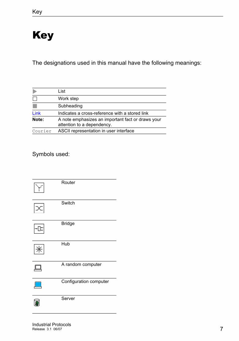
The designations used in this manual have the following meanings:
Symbols used:
ListWork stepSubheading
Link Indicates a cross-reference with a stored linkNote: A note emphasizes an important fact or draws your
attention to a dependency.Courier ASCII representation in user interface
Router
Switch
Bridge
Hub
A random computer
Configuration computer
Server
Industrial ProtocolsRelease 3.1 06/07 7

Key
PLC - Programmable logic controller
I/O - Robot
8Industrial Protocols
Release 3.1 06/07
Industrial Protocols
1 Industrial Protocols
For a long time, automation communication and office communication were on different paths. The requirements and the communication properties were too different. Office communication moves large quantities of data with low demands with respect to the transfer time. Automation communication moves small quantities of data with high demands with respect to the transfer time and availability.While the transmission devices in the office are usually kept in temperature-controlled, relatively clean rooms, the transmission devices used in automation are exposed to wider temperature ranges. Dirty, dusty and damp ambient conditions make additional demands on the quality of the transmission devices.
With the continued development of communication technology, the demands and the communication properties have moved closer together. The high bandwidths now available in Ethernet technology and the protocols they support enable large quantities to be transferred and exact transfer times to be defined.
With the creation of the first optical LAN to be active worldwide, at the University of Stuttgart in 1984, Hirschmann laid the foundation for industry-compatible office communication devices. Thanks to Hirschmann's initiative with the world's first rail hub in the 1990s, Ethernet transmission devices such as switches, routers and firewalls are now available for the toughest automation conditions.
The desire for uniform, continuous communication structures encouraged many manufacturers of automation devices to come together and use standards to aid the progress of communication technology in the automation sector. This is why we now have protocols that enable us to communicate via Ethernet from the office right down to the field level.
Industrial ProtocolsRelease 3.1 06/07 9
Industrial Protocols
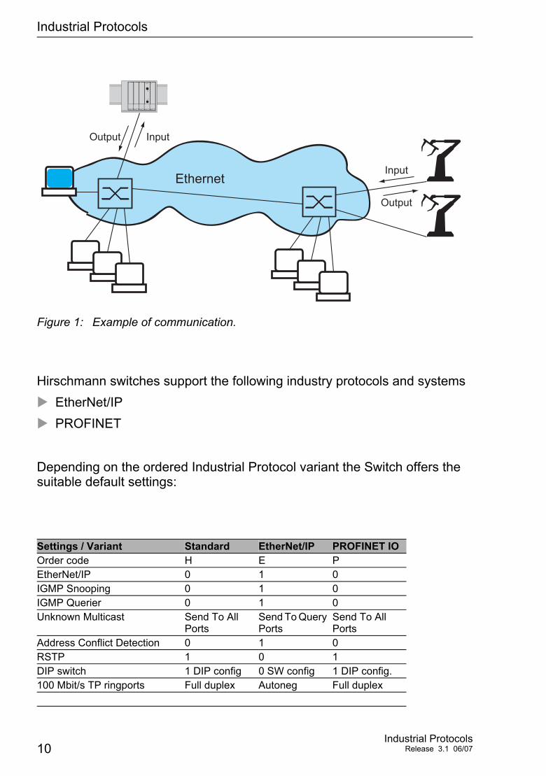
Figure 1: Example of communication.
Hirschmann switches support the following industry protocols and systemsEtherNet/IPPROFINET
Depending on the ordered Industrial Protocol variant the Switch offers the suitable default settings:
Settings / Variant Standard EtherNet/IP PROFINET IOOrder code H E PEtherNet/IP 0 1 0IGMP Snooping 0 1 0IGMP Querier 0 1 0Unknown Multicast Send To All
PortsSend To Query Ports
Send To All Ports
Address Conflict Detection 0 1 0RSTP 1 0 1DIP switch 1 DIP config 0 SW config 1 DIP config.100 Mbit/s TP ringports Full duplex Autoneg Full duplex
InputOutput
EthernetInput
Output
10Industrial Protocols
Release 3.1 06/07

Industrial Protocols
PROFINET IO 0 0 1Boot-Modus DHCP DHCP LokalVLAN 0 Transparent Modus 0 0 1HiDiscovery Read/Write Read/Write ReadOnlysysName Product name
+ 3 Byte MACProduct name + 3 Byte MAC
empty
Settings / Variant Standard EtherNet/IP PROFINET IO
Industrial ProtocolsRelease 3.1 06/07 11

Industrial Protocols
12Industrial Protocols
Release 3.1 06/07
EtherNet/IP
2 EtherNet/IP
EtherNet/IP, which is accepted worldwide, is an industrial communication protocol standardized by ODVA (Open DeviceNet Vendor Association) on the basis of Ethernet. It is based on the widely used transport protocols TCP/IP and UDP/IP (standard). EtherNet/IP thus provides a wide basis, supported by leading manufacturers, for effective data communication in the industry sector.
EtherNet/IP adds the industry protocol CIP (Common Industrial Protocol) to the Ethernet as an application level for automation applications. Ethernet is thus ideally suited to the industrial control technology sector.
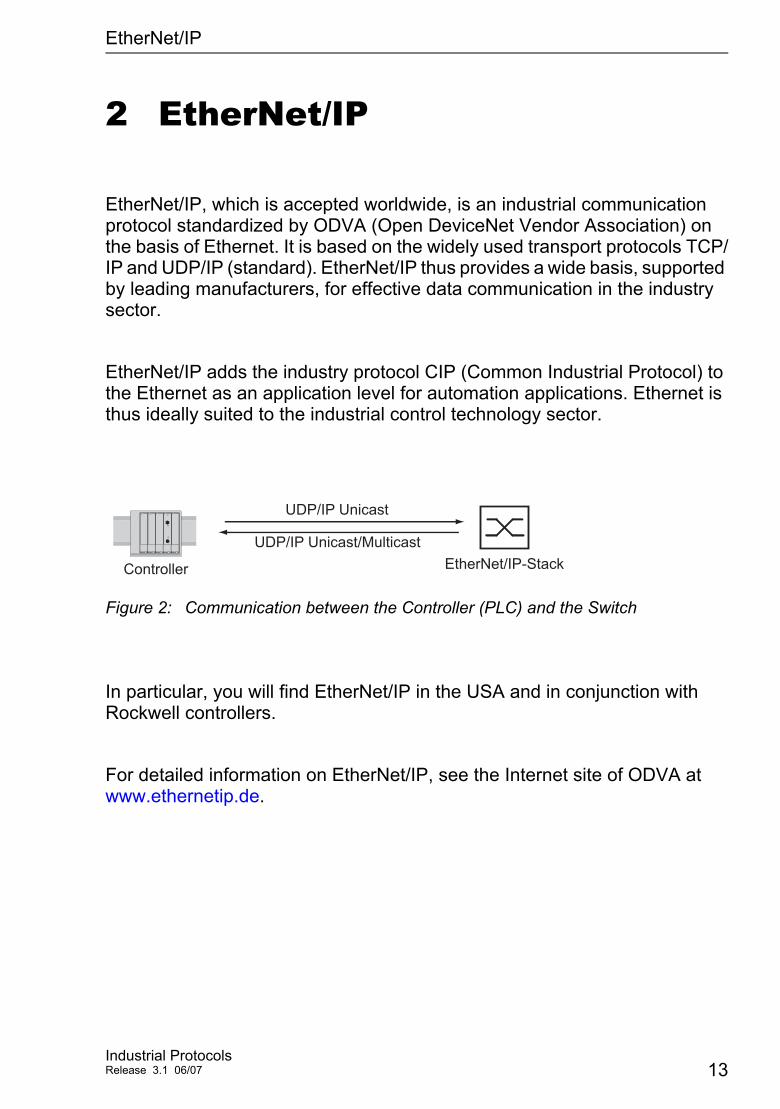
Figure 2: Communication between the Controller (PLC) and the Switch
In particular, you will find EtherNet/IP in the USA and in conjunction with Rockwell controllers.
For detailed information on EtherNet/IP, see the Internet site of ODVA at www.ethernetip.de.
UDP/IP Unicast
EtherNet/IP-StackController
UDP/IP Unicast/Multicast
Industrial ProtocolsRelease 3.1 06/07 13
EtherNet/IP 2.1 Integration in Control System
2.1 Integration in Control System
After installing and connecting the Switch, you configure it according to the “Basic Configuration” user manual. Then:
Use the Web-based interface in the Switching:Multicasts dialog to check whether the IGMP Snooping is activated.
Use the Web-based interface in the Advanced:Industry Protocols dialog to check whether EtherNet/IP is activated.
Use the Web-based interface in the Advanced:Industry Protocols dialog to load the EDS (= EtherNet/IP configuration file) and the Icon onto your local computer.
Note: If EtherNet/IP and the Router function are enabled concurrently mal-functions of EtherNet/IP may occur, e.g. in conjunction with „RS Who”.
Disable Router function via Web-based Interface: Dialog Routing:Global.Disable Router function via Command Line Interface: in configuration mode with the command no ip routing.
14Industrial Protocols
Release 3.1 06/07
EtherNet/IP 2.1 Integration in Control System
Configuration of the PLC using the example of the Rockwell software
Open the “EDS Hardware Installation Tool” of RSLinx.Use the “EDS Hardware Installation Tool” to add the EDS file.Restart the “RSLinx” service so that RSLinx takes over the EDS file of the Switch.Use RSLinx to check whether RSLinx has detected the Switch.Open your Logix 5000 project.Integrate the Switch into the Ethernet port of the controller as a new module (Generic Ethernet Module).
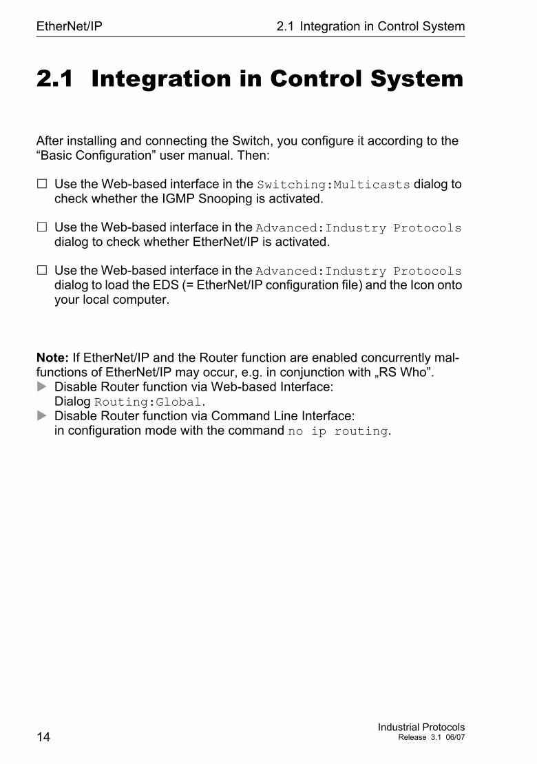
Figure 3: Integrating a new module into Logix 5000
Setting I/O connection Input only Listen onlyComm Format: Data - DINT Data - DINT Input Data - DINT -
Run/ProgramIP-Address IP address of the
SwitchIP address of the Switch
IP address of the Switch
Input Assembly Instance 2 2 2Input Size 7
(MACH 4000: 11)7 (MACH 4000: 11)
7 (MACH 4000: 11)
Output Assembly Instance 1 254 255Output Size 1
(MACH 4000: 2)0 0
Configuration Assembly Instance 3 3 3Configuration Size 0 0 0
Table 1: Settings for integrating a Generic Ethernet Module
Industrial ProtocolsRelease 3.1 06/07 15
EtherNet/IP 2.1 Integration in Control System
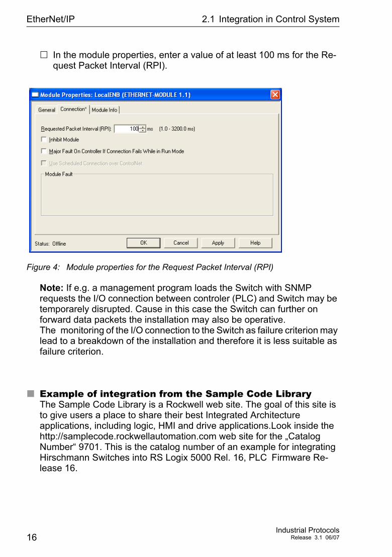
In the module properties, enter a value of at least 100 ms for the Re-quest Packet Interval (RPI).
Figure 4: Module properties for the Request Packet Interval (RPI)
Note: If e.g. a management program loads the Switch with SNMP requests the I/O connection between controler (PLC) and Switch may be temporarely disrupted. Cause in this case the Switch can further on forward data packets the installation may also be operative. The monitoring of the I/O connection to the Switch as failure criterion may lead to a breakdown of the installation and therefore it is less suitable as failure criterion.
Example of integration from the Sample Code LibraryThe Sample Code Library is a Rockwell web site. The goal of this site is to give users a place to share their best Integrated Architecture applications, including logic, HMI and drive applications.Look inside the http://samplecode.rockwellautomation.com web site for the „Catalog Number“ 9701. This is the catalog number of an example for integrating Hirschmann Switches into RS Logix 5000 Rel. 16, PLC Firmware Re-lease 16.
16Industrial Protocols
Release 3.1 06/07
EtherNet/IP 2.2 EtherNet/IP Parameters
2.2 EtherNet/IP Parameters
2.2.1 Identity Objekt
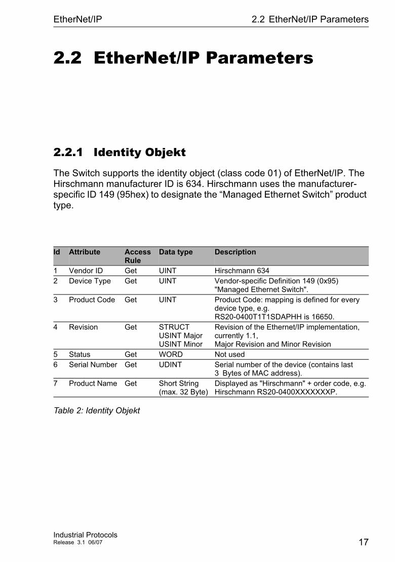
The Switch supports the identity object (class code 01) of EtherNet/IP. The Hirschmann manufacturer ID is 634. Hirschmann uses the manufacturer-specific ID 149 (95hex) to designate the “Managed Ethernet Switch” product type.
Id Attribute Access Rule
Data type Description
1 Vendor ID Get UINT Hirschmann 6342 Device Type Get UINT Vendor-specific Definition 149 (0x95)
"Managed Ethernet Switch". 3 Product Code Get UINT Product Code: mapping is defined for every
device type, e.g. RS20-0400T1T1SDAPHH is 16650.
4 Revision Get STRUCT USINT Major USINT Minor
Revision of the Ethernet/IP implementation, currently 1.1, Major Revision and Minor Revision
5 Status Get WORD Not used6 Serial Number Get UDINT Serial number of the device (contains last
3 Bytes of MAC address).7 Product Name Get Short String
(max. 32 Byte)Displayed as "Hirschmann" + order code, e.g. Hirschmann RS20-0400XXXXXXXP.
Table 2: Identity Objekt
Industrial ProtocolsRelease 3.1 06/07 17
EtherNet/IP 2.2 EtherNet/IP Parameters
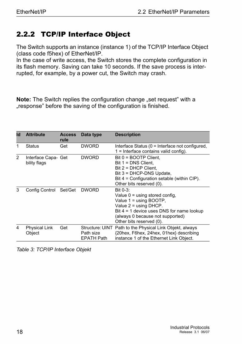
2.2.2 TCP/IP Interface Object
The Switch supports an instance (instance 1) of the TCP/IP Interface Object (class code f5hex) of EtherNet/IP. In the case of write access, the Switch stores the complete configuration in its flash memory. Saving can take 10 seconds. If the save process is inter-rupted, for example, by a power cut, the Switch may crash.
Note: The Switch replies the configuration change „set request” with a „response” before the saving of the configuration is finished.
Id Attribute Access rule
Data type Description
1 Status Get DWORD Interface Status (0 = Interface not configured, 1 = Interface contains valid config).
2 Interface Capa-bility flags
Get DWORD Bit 0 = BOOTP Client, Bit 1 = DNS Client, Bit 2 = DHCP Client, Bit 3 = DHCP-DNS Update, Bit 4 = Configuration setable (within CIP). Other bits reserved (0).
3 Config Control Set/Get DWORD Bit 0-3: Value 0 = using stored config, Value 1 = using BOOTP, Value 2 = using DHCP. Bit 4 = 1 device uses DNS for name lookup (always 0 because not supported) Other bits reserved (0).
4 Physical Link Object
Get Structure: UINT Path size EPATH Path
Path to the Physical Link Objekt, always {20hex, F6hex, 24hex, 01hex} describing instance 1 of the Ethernet Link Object.
Table 3: TCP/IP Interface Objekt
18Industrial Protocols
Release 3.1 06/07
EtherNet/IP 2.2 EtherNet/IP Parameters
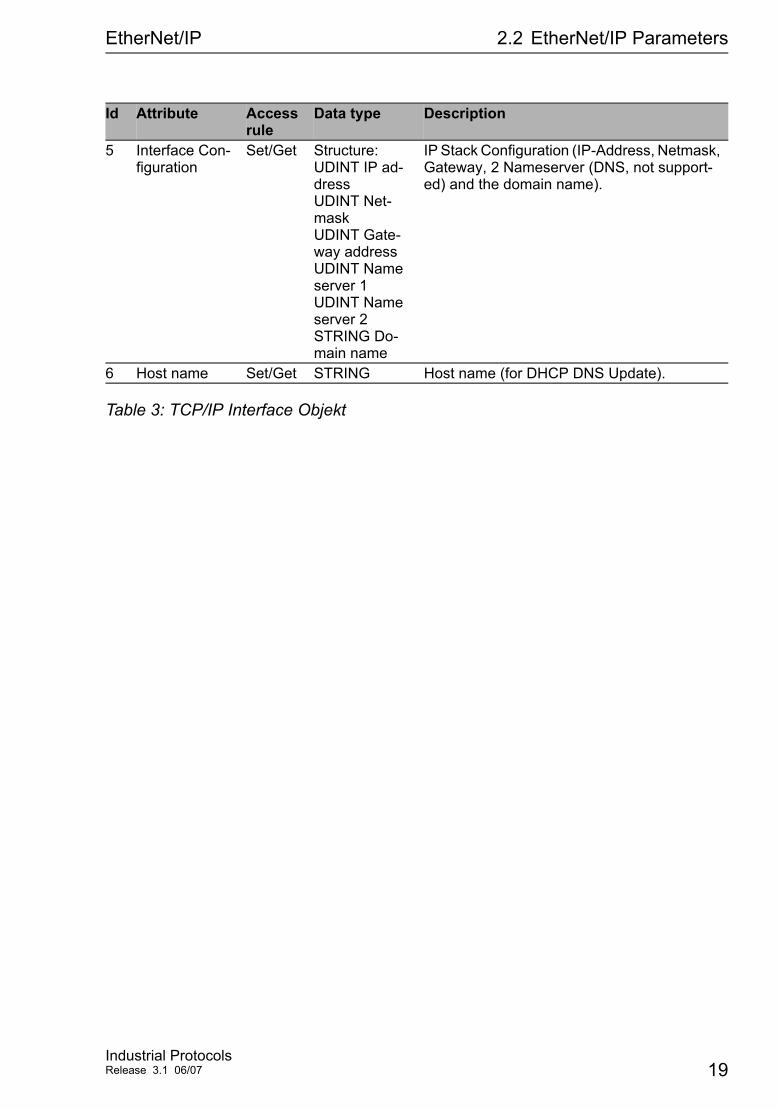
5 Interface Con-figuration
Set/Get Structure: UDINT IP ad-dress UDINT Net-mask UDINT Gate-way address UDINT Name server 1 UDINT Name server 2 STRING Do-main name
IP Stack Configuration (IP-Address, Netmask, Gateway, 2 Nameserver (DNS, not support-ed) and the domain name).
6 Host name Set/Get STRING Host name (for DHCP DNS Update).
Id Attribute Access rule
Data type Description
Table 3: TCP/IP Interface Objekt
Industrial ProtocolsRelease 3.1 06/07 19
EtherNet/IP 2.2 EtherNet/IP Parameters
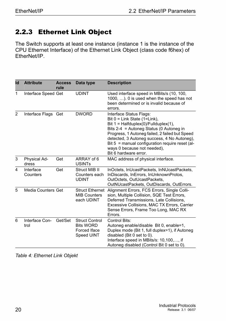
2.2.3 Ethernet Link Object
The Switch supports at least one instance (instance 1 is the instance of the CPU Ethernet Interface) of the Ethernet Link Object (class code f6hex) of EtherNet/IP.
Id Attribute Access rule
Data type Description
1 Interface Speed Get UDINT Used interface speed in MBits/s (10, 100, 1000, …). 0 is used when the speed has not been determined or is invalid because of errors.
2 Interface Flags Get DWORD Interface Status Flags: Bit 0 = Link State (1=Link), Bit 1 = Halfduplex(0)/Fullduplex(1), Bits 2-4 = Autoneg Status (0 Autoneg in Progress, 1 Autoneg failed, 2 failed but Speed detected, 3 Autoneg success, 4 No Autoneg), Bit 5 = manual configuration require reset (al-ways 0 because not needed), Bit 6 hardware error.
3 Physical Ad-dress
Get ARRAY of 6 USINTs
MAC address of physical interface.
4 Interface Counters
Get Struct MIB II Counters each UDINT
InOctets, InUcastPackets, InNUcastPackets, InDiscards, InErrors, InUnknownProtos, OutOctets, OutUcastPackets, OutNUcastPackets, OutDiscards, OutErrors.
5 Media Counters Get Struct Ethernet MIB Counters each UDINT
Alignment Errors, FCS Errors, Single Colli-sion, Multiple Collision, SQE Test Errors, Deferred Transmissions, Late Collisions, Excessive Collisions, MAC TX Errors, Carrier Sense Errors, Frame Too Long, MAC RX Errors.
6 Interface Con-trol
Get/Set Struct Control Bits WORD Forced Iface Speed UINT
Control Bits: Autoneg enable/disable Bit 0, enable=1, Duplex mode (Bit 1, full duplex=1), if Autoneg disabled (Bit 0 set to 0). Interface speed in MBits/s: 10,100,…, if Autoneg disabled (Control Bit 0 set to 0).
Table 4: Ethernet Link Objekt
20Industrial Protocols
Release 3.1 06/07
EtherNet/IP 2.2 EtherNet/IP Parameters
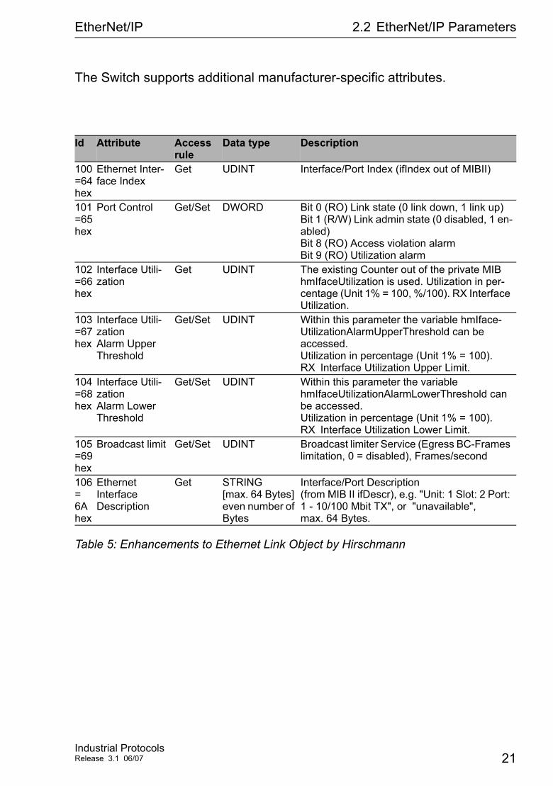
The Switch supports additional manufacturer-specific attributes.
Id Attribute Access rule
Data type Description
100=64 hex
Ethernet Inter-face Index
Get UDINT Interface/Port Index (ifIndex out of MIBII)
101=65 hex
Port Control Get/Set DWORD Bit 0 (RO) Link state (0 link down, 1 link up) Bit 1 (R/W) Link admin state (0 disabled, 1 en-abled) Bit 8 (RO) Access violation alarm Bit 9 (RO) Utilization alarm
102=66 hex
Interface Utili-zation
Get UDINT The existing Counter out of the private MIB hmIfaceUtilization is used. Utilization in per-centage (Unit 1% = 100, %/100). RX Interface Utilization.
103=67 hex
Interface Utili-zation Alarm Upper Threshold
Get/Set UDINT Within this parameter the variable hmIface-UtilizationAlarmUpperThreshold can be accessed. Utilization in percentage (Unit 1% = 100). RX Interface Utilization Upper Limit.
104=68 hex
Interface Utili-zation Alarm Lower Threshold
Get/Set UDINT Within this parameter the variable hmIfaceUtilizationAlarmLowerThreshold can be accessed. Utilization in percentage (Unit 1% = 100). RX Interface Utilization Lower Limit.
105=69 hex
Broadcast limit Get/Set UDINT Broadcast limiter Service (Egress BC-Frames limitation, 0 = disabled), Frames/second
106= 6A hex
Ethernet Interface Description
Get STRING [max. 64 Bytes] even number of Bytes
Interface/Port Description (from MIB II ifDescr), e.g. "Unit: 1 Slot: 2 Port: 1 - 10/100 Mbit TX", or "unavailable", max. 64 Bytes.
Table 5: Enhancements to Ethernet Link Object by Hirschmann
Industrial ProtocolsRelease 3.1 06/07 21
EtherNet/IP 2.2 EtherNet/IP Parameters
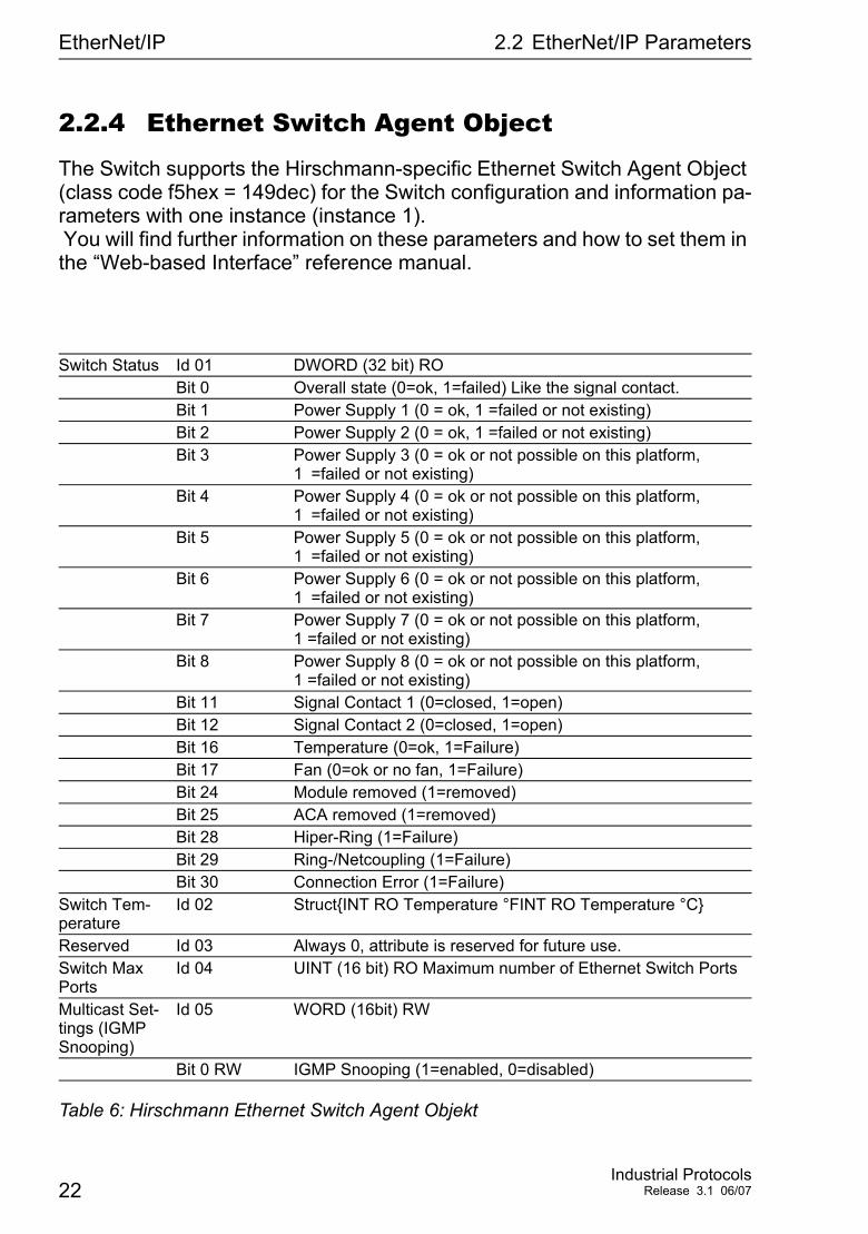
2.2.4 Ethernet Switch Agent Object
The Switch supports the Hirschmann-specific Ethernet Switch Agent Object (class code f5hex = 149dec) for the Switch configuration and information pa-rameters with one instance (instance 1). You will find further information on these parameters and how to set them in the “Web-based Interface” reference manual.
Switch Status Id 01 DWORD (32 bit) ROBit 0 Overall state (0=ok, 1=failed) Like the signal contact.Bit 1 Power Supply 1 (0 = ok, 1 =failed or not existing)Bit 2 Power Supply 2 (0 = ok, 1 =failed or not existing)Bit 3 Power Supply 3 (0 = ok or not possible on this platform,
1 =failed or not existing)Bit 4 Power Supply 4 (0 = ok or not possible on this platform,
1 =failed or not existing)Bit 5 Power Supply 5 (0 = ok or not possible on this platform,
1 =failed or not existing)Bit 6 Power Supply 6 (0 = ok or not possible on this platform,
1 =failed or not existing)Bit 7 Power Supply 7 (0 = ok or not possible on this platform,
1 =failed or not existing)Bit 8 Power Supply 8 (0 = ok or not possible on this platform,
1 =failed or not existing)Bit 11 Signal Contact 1 (0=closed, 1=open)Bit 12 Signal Contact 2 (0=closed, 1=open)Bit 16 Temperature (0=ok, 1=Failure)Bit 17 Fan (0=ok or no fan, 1=Failure)Bit 24 Module removed (1=removed)Bit 25 ACA removed (1=removed)Bit 28 Hiper-Ring (1=Failure)Bit 29 Ring-/Netcoupling (1=Failure)Bit 30 Connection Error (1=Failure)
Switch Tem-perature
Id 02 Struct{INT RO Temperature °FINT RO Temperature °C}
Reserved Id 03 Always 0, attribute is reserved for future use.Switch Max Ports
Id 04 UINT (16 bit) RO Maximum number of Ethernet Switch Ports
Multicast Set-tings (IGMP Snooping)
Id 05 WORD (16bit) RW
Bit 0 RW IGMP Snooping (1=enabled, 0=disabled)
Table 6: Hirschmann Ethernet Switch Agent Objekt
22Industrial Protocols
Release 3.1 06/07
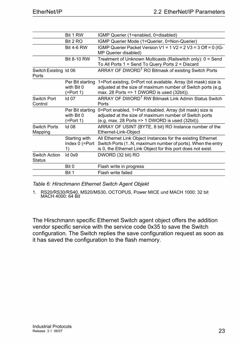
EtherNet/IP 2.2 EtherNet/IP Parameters
The Hirschmann specific Ethernet Switch agent object offers the addition vendor specific service with the service code 0x35 to save the Switch configuration. The Switch replies the save configuration request as soon as it has saved the configuration to the flash memory.
Bit 1 RW IGMP Querier (1=enabled, 0=disabled)Bit 2 RO IGMP Querier Mode (1=Querier, 0=Non-Querier)Bit 4-6 RW IGMP Querier Packet Version V1 = 1 V2 = 2 V3 = 3 Off = 0 (IG-
MP Querier disabled)Bit 8-10 RW Treatment of Unknown Multicasts (Railswitch only): 0 = Send
To All Ports 1 = Send To Query Ports 2 = DiscardSwitch Existing Ports
Id 06 ARRAY OF DWORD1 RO Bitmask of existing Switch Ports
Per Bit starting with Bit 0 (=Port 1)
1=Port existing, 0=Port not available. Array (bit mask) size is adjusted at the size of maximum number of Switch ports (e.g. max. 28 Ports => 1 DWORD is used (32bit)).
Switch Port Control
Id 07 ARRAY OF DWORD1 RW Bitmask Link Admin Status Switch Ports
Per Bit starting with Bit 0 (=Port 1)
0=Port enabled, 1=Port disabled. Array (bit mask) size is adjusted at the size of maximum number of Switch ports (e.g. max. 28 Ports => 1 DWORD is used (32bit)).
Switch Ports Mapping
Id 08 ARRAY OF USINT (BYTE, 8 bit) RO Instance number of the Ethernet-Link-Object
Starting with Index 0 (=Port 1)
All Ethernet Link Object Instances for the existing Ethernet Switch Ports (1..N, maximum number of ports). When the entry is 0, the Ethernet Link Object for this port does not exist.
Switch Action Status
Id 0x9 DWORD (32 bit) RO
Bit 0 Flash write in progressBit 1 Flash write failed
1. RS20/RS30/RS40, MS20/MS30, OCTOPUS, Power MICE und MACH 1000: 32 bit MACH 4000: 64 Bit
Table 6: Hirschmann Ethernet Switch Agent Objekt
Industrial ProtocolsRelease 3.1 06/07 23
EtherNet/IP 2.2 EtherNet/IP Parameters
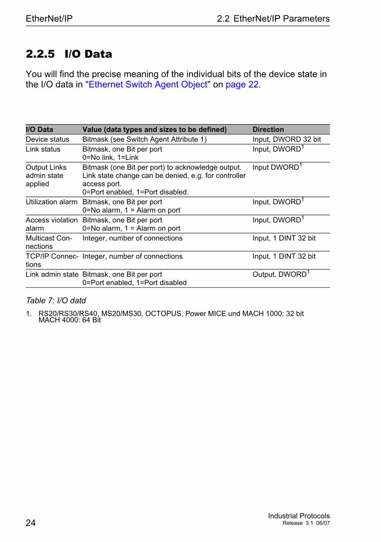
2.2.5 I/O Data
You will find the precise meaning of the individual bits of the device state in the I/O data in "Ethernet Switch Agent Object" on page 22.
I/O Data Value (data types and sizes to be defined) DirectionDevice status Bitmask (see Switch Agent Attribute 1) Input, DWORD 32 bitLink status Bitmask, one Bit per port
0=No link, 1=LinkInput, DWORD1
1. RS20/RS30/RS40, MS20/MS30, OCTOPUS, Power MICE und MACH 1000: 32 bit MACH 4000: 64 Bit
Output Links admin state applied
Bitmask (one Bit per port) to acknowledge output. Link state change can be denied, e.g. for controller access port. 0=Port enabled, 1=Port disabled.
Input DWORD1
Utilization alarm Bitmask, one Bit per port 0=No alarm, 1 = Alarm on port
Input, DWORD1
Access violation alarm
Bitmask, one Bit per port 0=No alarm, 1 = Alarm on port
Input, DWORD1
Multicast Con-nections
Integer, number of connections Input, 1 DINT 32 bit
TCP/IP Connec-tions
Integer, number of connections Input, 1 DINT 32 bit
Link admin state Bitmask, one Bit per port 0=Port enabled, 1=Port disabled
Output, DWORD1
Table 7: I/O datd
24Industrial Protocols
Release 3.1 06/07
EtherNet/IP 2.2 EtherNet/IP Parameters
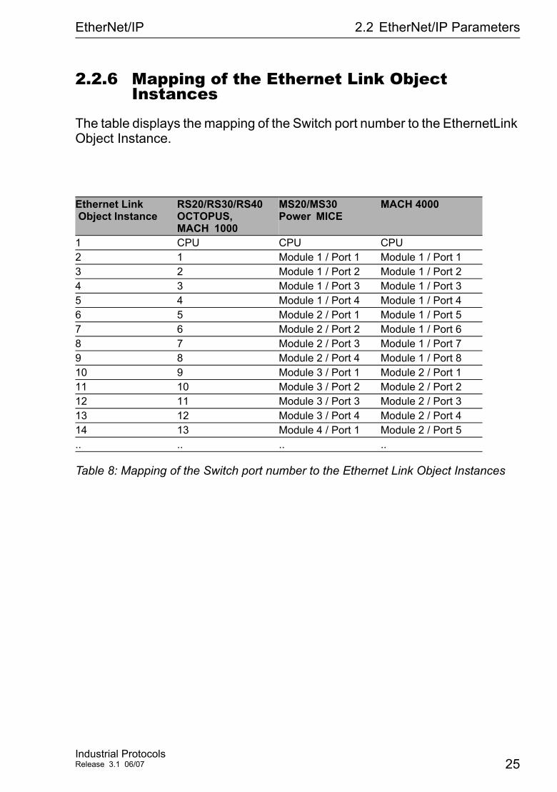
2.2.6 Mapping of the Ethernet Link Object Instances
The table displays the mapping of the Switch port number to the EthernetLink Object Instance.
Ethernet Link Object Instance
RS20/RS30/RS40 OCTOPUS, MACH 1000
MS20/MS30 Power MICE
MACH 4000
1 CPU CPU CPU2 1 Module 1 / Port 1 Module 1 / Port 13 2 Module 1 / Port 2 Module 1 / Port 24 3 Module 1 / Port 3 Module 1 / Port 35 4 Module 1 / Port 4 Module 1 / Port 46 5 Module 2 / Port 1 Module 1 / Port 57 6 Module 2 / Port 2 Module 1 / Port 68 7 Module 2 / Port 3 Module 1 / Port 79 8 Module 2 / Port 4 Module 1 / Port 810 9 Module 3 / Port 1 Module 2 / Port 111 10 Module 3 / Port 2 Module 2 / Port 212 11 Module 3 / Port 3 Module 2 / Port 313 12 Module 3 / Port 4 Module 2 / Port 414 13 Module 4 / Port 1 Module 2 / Port 5.. .. .. ..
Table 8: Mapping of the Switch port number to the Ethernet Link Object Instances
Industrial ProtocolsRelease 3.1 06/07 25
EtherNet/IP 2.2 EtherNet/IP Parameters
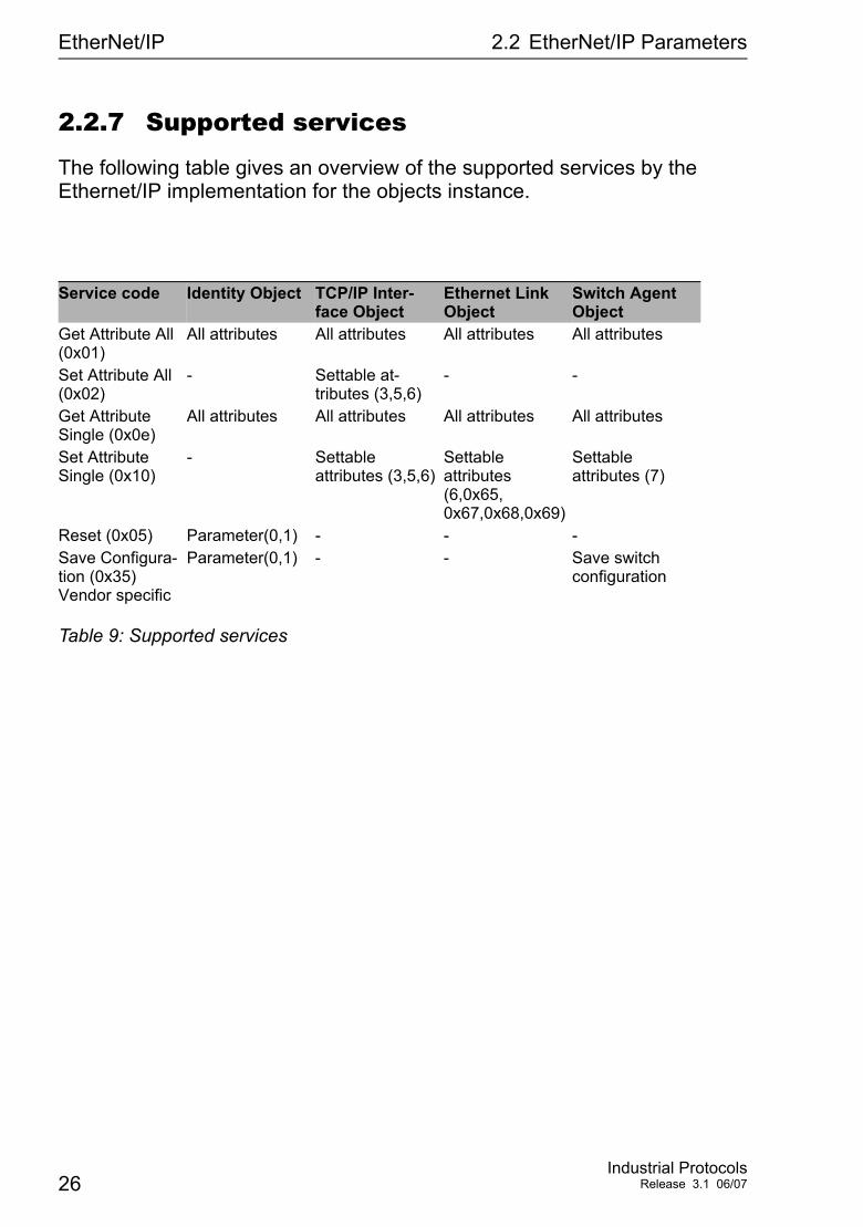
2.2.7 Supported services
The following table gives an overview of the supported services by the Ethernet/IP implementation for the objects instance.
Service code Identity Object TCP/IP Inter-face Object
Ethernet Link Object
Switch Agent Object
Get Attribute All (0x01)
All attributes All attributes All attributes All attributes
Set Attribute All (0x02)
- Settable at-tributes (3,5,6)
- -
Get Attribute Single (0x0e)
All attributes All attributes All attributes All attributes
Set Attribute Single (0x10)
- Settable attributes (3,5,6)
Settable attributes (6,0x65, 0x67,0x68,0x69)
Settable attributes (7)
Reset (0x05) Parameter(0,1) - - -Save Configura-tion (0x35) Vendor specific
Parameter(0,1) - - Save switch configuration
Table 9: Supported services
26Industrial Protocols
Release 3.1 06/07
PROFINET IO
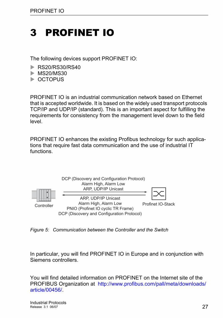
3 PROFINET IO
The following devices support PROFINET IO:RS20/RS30/RS40MS20/MS30OCTOPUS
PROFINET IO is an industrial communication network based on Ethernet that is accepted worldwide. It is based on the widely used transport protocols TCP/IP and UDP/IP (standard). This is an important aspect for fulfilling the requirements for consistency from the management level down to the field level.
PROFINET IO enhances the existing Profibus technology for such applica-tions that require fast data communication and the use of industrial IT functions.
Figure 5: Communication between the Controller and the Switch
In particular, you will find PROFINET IO in Europe and in conjunction with Siemens controllers.
You will find detailed information on PROFINET on the Internet site of the PROFIBUS Organization at http://www.profibus.com/pall/meta/downloads/article/00456/.
DCP (Discovery and Configuration Protocol)Alarm High, Alarm LowARP, UDP/IP Unicast
Profinet IO-StackController
ARP, UDP/IP UnicastAlarm High, Alarm Low
PNIO (Profinet IO cyclic TR Frame)DCP (Discovery and Configuration Protocol)
Industrial ProtocolsRelease 3.1 06/07 27
PROFINET IO
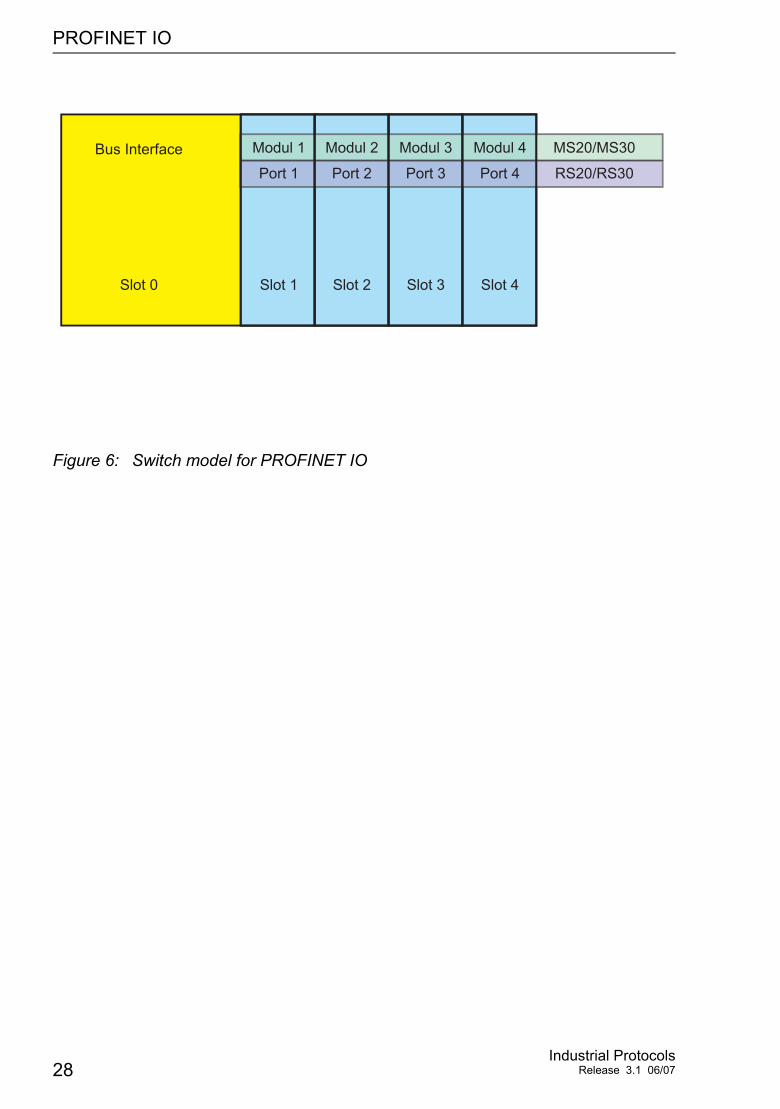
Figure 6: Switch model for PROFINET IO
Bus Interface Modul 4Modul 3Modul 2Modul 1
Port 4
MS20/MS30
RS20/RS30Port 3Port 2Port 1
Slot 4Slot 3Slot 2Slot 1Slot 0
28Industrial Protocols
Release 3.1 06/07
PROFINET IO 3.1 Integration in Control System
3.1 Integration in Control System
3.1.1 Configuration of the Switch
After installing and connecting the Switch, you configure it according to the "Basic Configuration" user manual:
Use the Web-based interface in the Basic Settings:Network dialog to check whether Local is selected in the "Mode" frame.
Use the Web-based interface in the Switching:VLAN:Global dialog to check whether "VLAN 0 Transparent Mode" is selected.
Use the Web-based interface in the Advanced:Industry Protocols dialog to check whether Profinet IO is activated.
Use the Web-based interface in the Advanced:Industry Protocols dialog to download the GSDML (= Generic Station Description Markup Language) and the Icon onto your local computer.
Configure the Alarm setting and the Threshold value for the alarms you want to monitor.
Industrial ProtocolsRelease 3.1 06/07 29
PROFINET IO 3.1 Integration in Control System
3.1.2 Configuration of the PLC
The following illustrates the configuration of the PLC using the example of the Simatic S7 software from Siemens, and assumes that you are familiar with operating the software.
Note: If e.g. a management program loads the Switch with SNMP requests the I/O connection between controler (PLC) and Switch may be temporarely disrupted. Cause in this case the Switch can further on forward data packets the installation may also be operative. The monitoring of the I/O connection to the Switch as failure criterion may lead to a breakdown of the installation and therefore it is less suitable as failure criterion.
As default the PLC takes the disruption of the I/O connection to the Switch as failure criterion. This leads to a breakdown of the installation. Take Step7 program technical measures to change the default settings.
Incorporating the Switch in the configurationOpen the "Simatic Manager" from Simatic S7.Open your project.Go to the hardware configuration.Install the GSD(ML) file using Extras:Install GSD File. Select the GSDML file previously downloaded. Simatic S7 installs the file to-gether with the Icon. You will find the new Switch under Profinet IO:Other Field Devices:Switching Devices:Hirschmann...Use Drag & Drop to pull the Switch onto the bus cable.To give the Switch its name, select the Switch and in the menu bar choose Target System:Ethernet:Edit Ethernet Partici pants...
30Industrial Protocols
Release 3.1 06/07
PROFINET IO 3.1 Integration in Control System
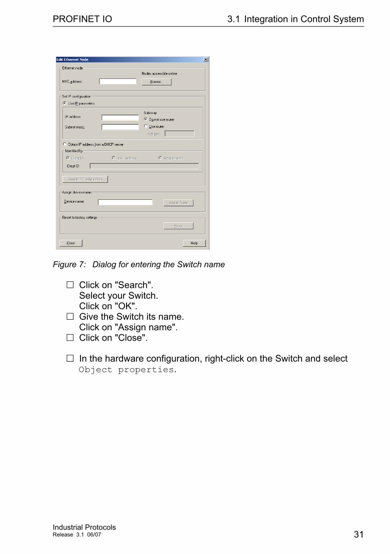
Figure 7: Dialog for entering the Switch name
Click on "Search". Select your Switch. Click on "OK".Give the Switch its name. Click on "Assign name".Click on "Close".
In the hardware configuration, right-click on the Switch and select Object properties.
Industrial ProtocolsRelease 3.1 06/07 31
PROFINET IO 3.1 Integration in Control System
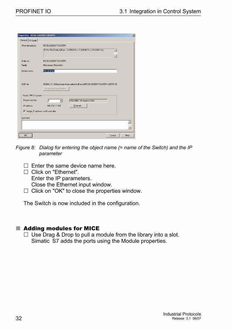
Figure 8: Dialog for entering the object name (= name of the Switch) and the IP parameter
Enter the same device name here.Click on "Ethernet". Enter the IP parameters. Close the Ethernet input window.Click on "OK" to close the properties window.
The Switch is now included in the configuration.
Adding modules for MICEUse Drag & Drop to pull a module from the library into a slot. Simatic S7 adds the ports using the Module properties.
32Industrial Protocols
Release 3.1 06/07
PROFINET IO 3.1 Integration in Control System
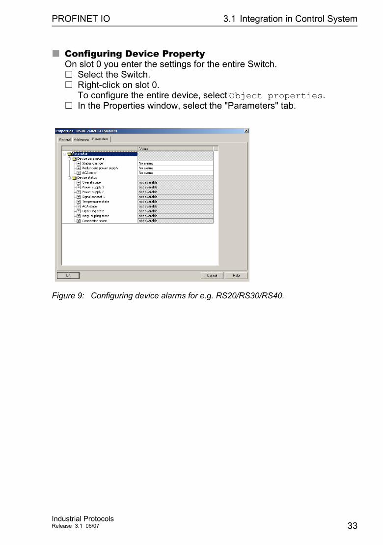
Configuring Device PropertyOn slot 0 you enter the settings for the entire Switch.
Select the Switch.Right-click on slot 0. To configure the entire device, select Object properties.In the Properties window, select the "Parameters" tab.
Figure 9: Configuring device alarms for e.g. RS20/RS30/RS40.
Industrial ProtocolsRelease 3.1 06/07 33
PROFINET IO 3.1 Integration in Control System
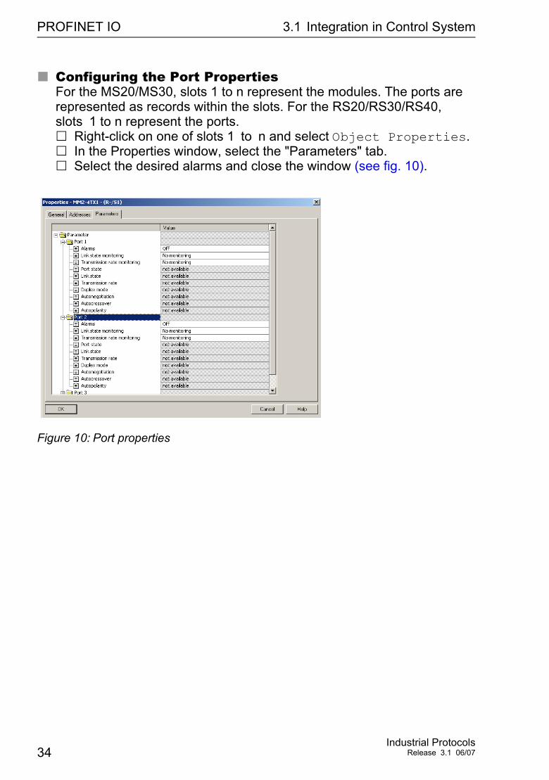
Configuring the Port Properties For the MS20/MS30, slots 1 to n represent the modules. The ports are represented as records within the slots. For the RS20/RS30/RS40, slots 1 to n represent the ports.
Right-click on one of slots 1 to n and select Object Properties. In the Properties window, select the "Parameters" tab.Select the desired alarms and close the window (see fig. 10).
Figure 10: Port properties
34Industrial Protocols
Release 3.1 06/07
PROFINET IO 3.2 PROFINET IO Parameters
3.2 PROFINET IO Parameters
3.2.1 Alarms
The Switch supports alarms on the device and port levels (see „Device State“ in the Basic Configuration User Manual or the Web-based Interface Refer-ence Manual.
Alarms on device level Change in device status - Failure of redundant power supply - Failure/removal of ACA
Alarms on port level - Change in link status - Specified transfer rate exceeded.
Table 10: Alarms supported
Industrial ProtocolsRelease 3.1 06/07 35
PROFINET IO 3.2 PROFINET IO Parameters
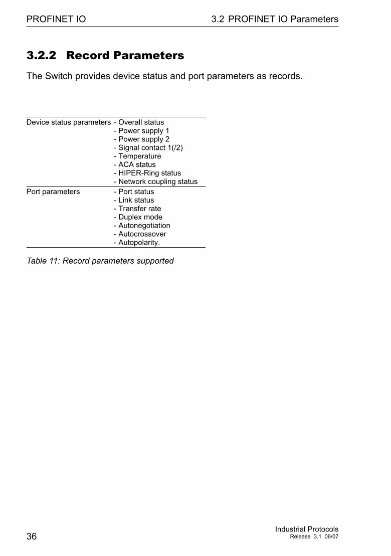
3.2.2 Record Parameters
The Switch provides device status and port parameters as records.
Device status parameters - Overall status - Power supply 1 - Power supply 2 - Signal contact 1(/2) - Temperature - ACA status - HIPER-Ring status - Network coupling status
Port parameters - Port status - Link status - Transfer rate - Duplex mode - Autonegotiation - Autocrossover - Autopolarity.
Table 11: Record parameters supported
36Industrial Protocols
Release 3.1 06/07
Reader´s comments
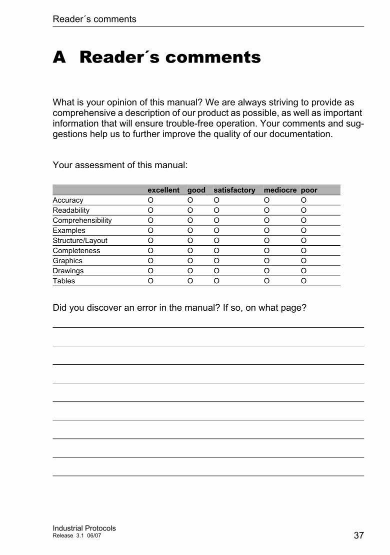
A Reader´s comments
What is your opinion of this manual? We are always striving to provide as comprehensive a description of our product as possible, as well as important information that will ensure trouble-free operation. Your comments and sug-gestions help us to further improve the quality of our documentation.
Your assessment of this manual:
Did you discover an error in the manual? If so, on what page?
excellent good satisfactory mediocre poorAccuracy O O O O OReadability O O O O OComprehensibility O O O O OExamples O O O O OStructure/Layout O O O O OCompleteness O O O O OGraphics O O O O ODrawings O O O O OTables O O O O O
Industrial ProtocolsRelease 3.1 06/07 37

Reader´s comments
Suggestions for improvement and additional information:
General comments:
Sender:
Dear User,
Please fill out and return this page by fax to the number +49 (0)7127/14-1798 orby mail to
Hirschmann Automation and Control GmbHDepartment AMMStuttgarter Str. 45-51
72654 NeckartenzlingenGermanyGermany
Company / Department:
Name / Telephone number: Street:
Zip code / City:
Date / Signature:
38Industrial Protocols
Release 3.1 06/07
Index
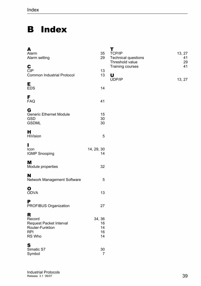
B Index
AAlarm 35Alarm setting 29
CCIP 13Common Industrial Protocol 13
EEDS 14
FFAQ 41
GGeneric Ethernet Module 15GSD 30GSDML 30
HHiVision 5
IIcon 14, 29, 30IGMP Snooping 14
MModule properties 32
NNetwork Management Software 5
OODVA 13
PPROFIBUS Organization 27
RRecord 34, 36Request Packet Interval 16Router-Funktion 14RPI 16RS Who 14
SSimatic S7 30Symbol 7
TTCP/IP 13, 27Technical questions 41Threshold value 29Training courses 41
UUDP/IP 13, 27
39Industrial ProtocolsRelease 3.1 06/07

Index
40Industrial Protocols
Release 3.1 06/07

Further support
C Further support
Technical questions and training coursesIn the event of technical queries, please talk to the Hirschmann contract partner responsible for looking after your account or directly to the Hirschmann office. You can find the addresses of our contract partners on the Internet: www.hirschmann-ac.com.
Our support line is also at your disposal:Tel. +49 1805 14-1538Fax +49 7127 14-1551
Answers to Frequently Asked Questions can be found on the Hirschmann internet site (www.hirschmann-ac.com) at the end oft the product sites in the FAQ category. The current training courses to technology and products can be found under http://www.hicomcenter.com.
Hirschmann Competence CenterIn the longterm, product excellence alone is not an absolute guarantee of a successful project implementation. Comprehensive service makes a difference worldwide. In the current scenario of global competition, the Hirschmann Competence Center stands head and shoulders above the competition with its comprehensive spectrum of innovative services:
Consulting incorporates comprehensive technical advice, from system evaluation through network planning to project planning.Training offers you an introduction to the technological fundamentals, product briefing and user training with certification.Support ranges from commissioning through the standby service to maintenance concepts.
With the Competence Center, you firmly rule out any compromise: the client-specific package leaves you free to choose the service components that you will use. Internet: http://www.hicomcenter.com.
Industrial ProtocolsRelease 3.1 06/07 41