Embed Size (px)
Citation preview
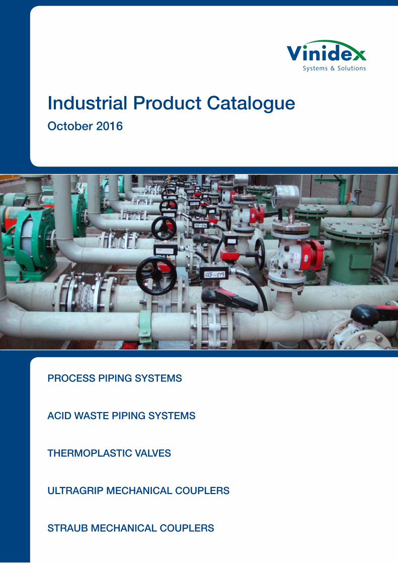
Industrial Product Catalogue October 2016
PROCESS PIPING SYSTEMS
ACID WASTE PIPING SYSTEMS
THERMOPLASTIC VALVES
ULTRAGRIP MECHANICAL COUPLERS
STRAUB MECHANICAL COUPLERS
Vinidex Pty Limited is Australia’s leading manufacturer and supplier of pipe systems and solutions for the transportation of fluid, data and energy. Vinidex is recognised internationally as a major participant in the pipe industry and as a quality manufacturer of PVC, Polyethylene (PE) and Polypropylene (PP) pipe systems.
From humble beginnings in 1960, Vinidex has grown to become Australia’s leading plastic pipes systems company. The company now has eleven manufacturing plants and thirteen distribution centres across Australia. Vinidex has products and systems solutions for a broad range of applications including plumbing, water supply, waste management, stormwater and drainage, mining, industrial, rural, irrigation, electrical, telecommunications and gas.
Proven long term performance and reliability of Vinidex products in major infrastructure and building projects has resulted in ongoing substitution of traditional materials such as metals, earthenware, concrete and fibre cement with better performing plastic pipes.
Vinidex is renowned for a commitment to technical advancement and product innovation. Our continuous evaluation programs examine new materials, processing technology and manufacturing equipment to ensure our continued high standard in the pipes and fittings industry.
Vinidex is recognised internationally as a major participant in the piping industry. We are represented and participate in Australian and ISO standards committees, Australian and International piping associations and the pipe industry generally. Our technologies and products are used in Europe, the USA and Africa. We have an ongoing presence in international developments in product and services to this industry.
As part of the world wide Aliaxis Group of companies Vinidex provides products, access to international technologies and innovative solutions that are world class. The Aliaxis Group is a leading global manufacturer and distributor of plastic pipe systems, present in over 40 countries, has more than 100 commercial entities and employs over 16 200 people.
Our global reach extends across six continents and gives us unrivalled access to the most advanced pipe systems in the world. We are able to source a variety of new pipes and fittings technologies never before seen in the Australian market. These products support our ever-growing and expanding range and allow us to maintain our position as Australia’s leading manufacturer and supplier of quality pipe systems and solutions.
At every level of Vinidex you will find a genuine commitment from our staff to exceed expectations and ensure that you are satisfied with the overall experience. We offer a total solutions service from supply, technical and design assistance right through to installation, testing and evaluation.
Having built an enviable reputation in Australia and supported by an emphasis on product quality and customer service, Vinidex will continue to lead the industry in the development, manufacture and delivery of plastic pipeline and conduit systems.
NATIONAL REACH.GLOBAL SUPPORT.
INDUSTRIAL PRODUCT CATALOGUE
PROCESS PIPING SYSTEMS 1
Xirtec 140 PVC 2
Corzan CPVC 9
Superflo ABS 15
DOUBLE CONTAINMENT SYSTEMS 37
ACID WASTE PIPING SYSTEMS 41
Vulcathene 42
THERMOPLASTIC VALVES 75
Ball Valves 76
Butterfly Valves 79
Check & Vent Valves 80
Diaphragm Valves 81
ULTRAGRIP MECHANICAL COUPLERS 83
STRAUB MECHANICAL COUPLERS 87
Process Piping SystemsVinidex offers a comprehensive range of integrated process piping systems – pipe, fittings and valves in ABS, PVC, CPVC, HDPE, PP and PVDF – designed to meet the temperature, pressure and size requirements of a wide range of chemical processing and similar industrial applications.
In addition to costing less than common and exotic metal systems, our thermoplastic process piping systems are lightweight, as well as easy to handle, store, cut and join, so transportation and installation cost are substantially lower.
When you specify a high-performance process piping system from Vinidex, you get the added benefits of a complete piping solution that is engineered for total integration, and backed by comprehensive support – all from one reliable source.
ii
Xirtec140 (PVC) and Corzan (CPVC) systems have been developed to meet industry demands for a complete Pipe, Valves and Fittings (PVF) package that is designed, produced and backed by a single manufacturer. These systems are engineered and manufactured to strict quality, performance and dimensional standards.
Our high-performance vinyl systems are designed to meet the temperature, pressure and size requirements of piping systems used in chemical processes and other industrial applications. They feature outstanding resistance to photo-degradation, creep stress and immunity to oxidation, and are exceptionally suited for use with a wide range of acids, alcohols, salts and halogens. The perfect extended service, low maintenance alternative to common and exotic metal systems.
Xirtec140 and Corzan pipe and fittings are available in Schedule 80, IPS.
Durapipe SuperFLO ABS combines corrosion resistance, toughness and economic benefits to provide tremendous advantage for low temperature fluid transportation.
SuperFLO ABS is a solvent welded, fully matched pipework system incorporating pipe, fittings and valves that is available in both imperial and metric sizes. SuperFLO ABS provides a wide temperature range and the system remains extremely ductile even at temperatures as low as -40°C.
Furthermore, SuperFLO ABS is extremely lightweight and is much easier to handle on-site than traditional materials especially during installation which can significantly reduce both time and cost.
superChilled & cold water pipework
FLO
1
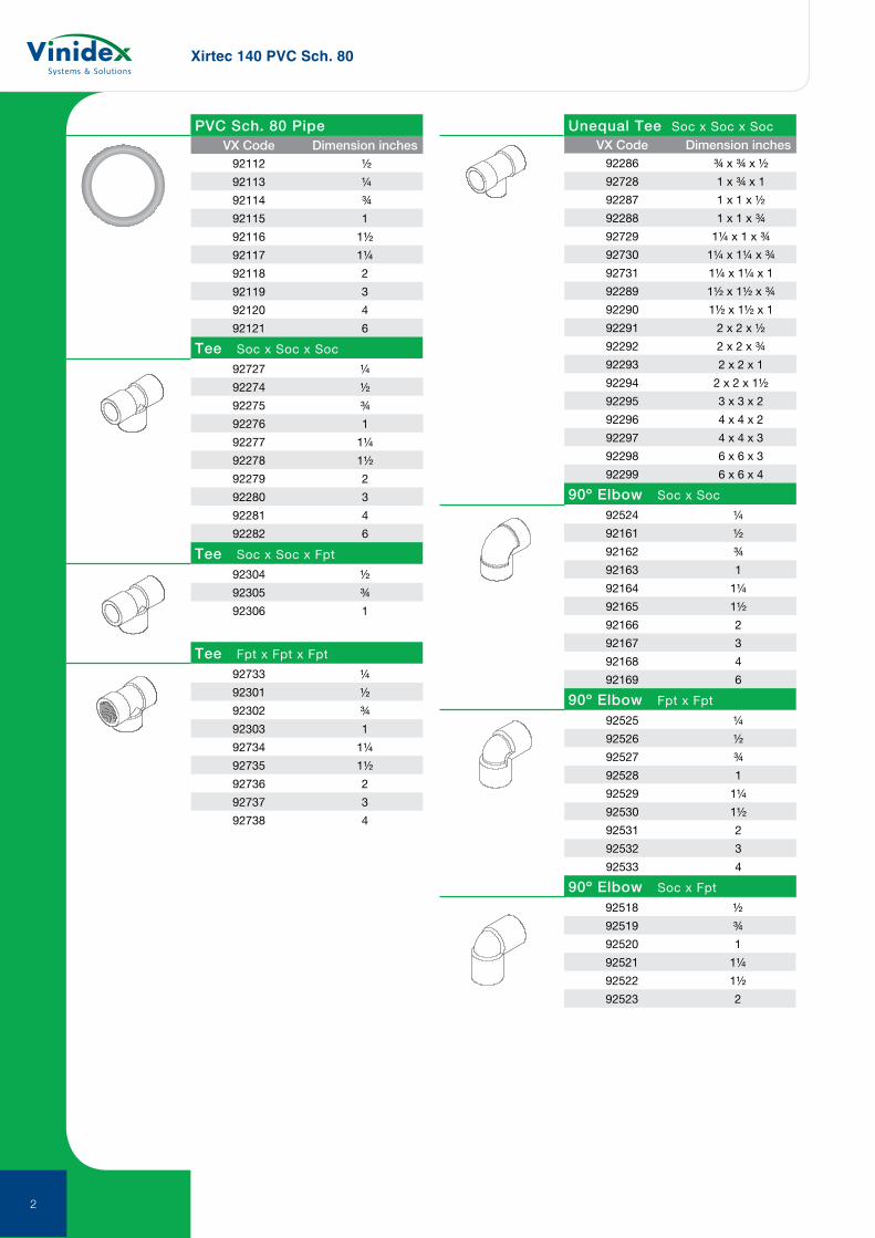
Xirtec 140 PVC Sch. 80
92727 ¼
92274 ½
92275 ¾
92276 1
92277 1¼
92278 1½
92279 2
92280 3
92281 4
92282 6
92304 ½
92305 ¾
92306 1
92733 ¼
92301 ½
92302 ¾
92303 1
92734 1¼
92735 1½
92736 2
92737 3
92738 4
VX Code Dimension inches92112 ½
92113 ¼
92114 ¾
92115 1
92116 1½
92117 1¼
92118 2
92119 3
92120 4
92121 6
VX Code Dimension inches92286 ¾ x ¾ x ½
92728 1 x ¾ x 1
92287 1 x 1 x ½
92288 1 x 1 x ¾
92729 1¼ x 1 x ¾
92730 1¼ x 1¼ x ¾
92731 1¼ x 1¼ x 1
92289 1½ x 1½ x ¾
92290 1½ x 1½ x 1
92291 2 x 2 x ½
92292 2 x 2 x ¾
92293 2 x 2 x 1
92294 2 x 2 x 1½
92295 3 x 3 x 2
92296 4 x 4 x 2
92297 4 x 4 x 3
92298 6 x 6 x 3
92299 6 x 6 x 4
Unequal Tee Soc x Soc x Soc
Tee Soc x Soc x Fpt
Tee Fpt x Fpt x Fpt
PVC Sch. 80 Pipe
Tee Soc x Soc x Soc
92524 ¼
92161 ½
92162 ¾
92163 1
92164 1¼
92165 1½
92166 2
92167 3
92168 4
92169 6
92525 ¼
92526 ½
92527 ¾
92528 1
92529 1¼
92530 1½
92531 2
92532 3
92533 4
92518 ½
92519 ¾
92520 1
92521 1¼
92522 1½
92523 2
90º Elbow Fpt x Fpt
90º Elbow Soc x Fpt
90º Elbow Soc x Soc
2
Xirtec 140 PVC Sch. 80
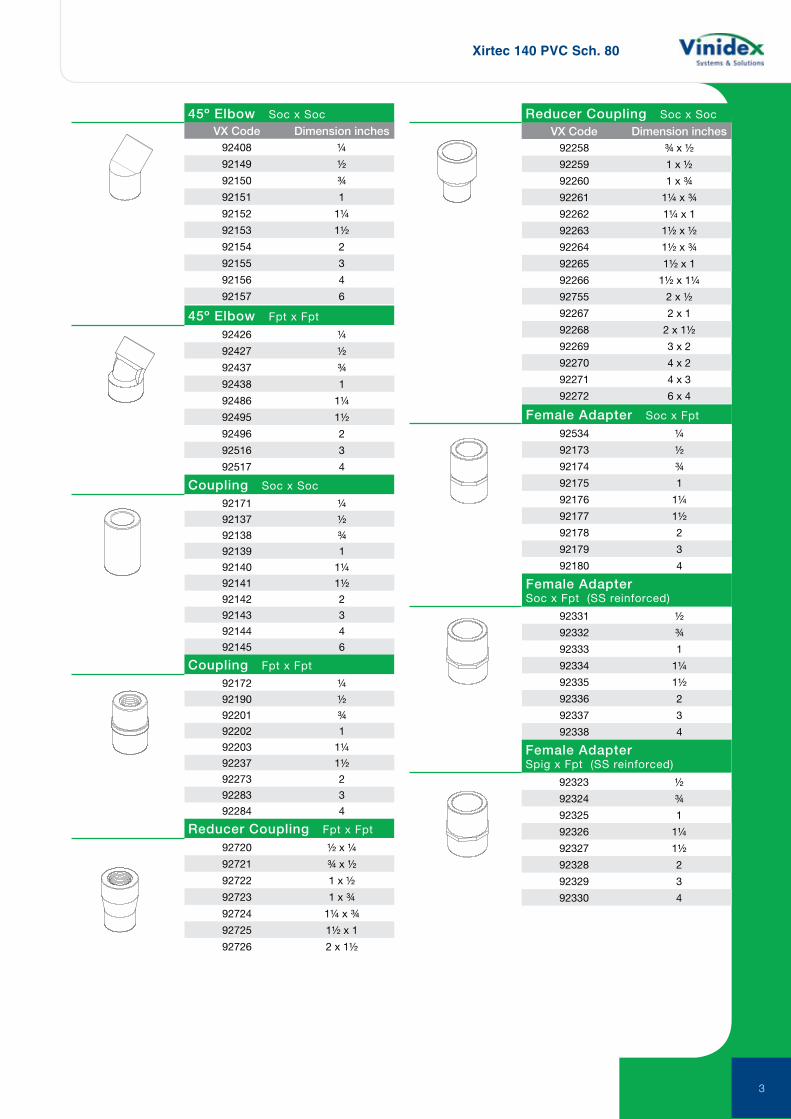
92408 ¼
92149 ½
92150 ¾
92151 1
92152 1¼
92153 1½
92154 2
92155 3
92156 4
92157 6
45º Elbow Soc x Soc
VX Code Dimension inches
92426 ¼
92427 ½
92437 ¾
92438 1
92486 1¼
92495 1½
92496 2
92516 3
92517 4
45º Elbow Fpt x Fpt
Coupling Soc x Soc
92171 ¼
92137 ½
92138 ¾
92139 1
92140 1¼
92141 1½
92142 2
92143 3
92144 4
92145 6
Coupling Fpt x Fpt
Reducer Coupling Fpt x Fpt
92720 ½ x ¼
92721 ¾ x ½
92722 1 x ½
92723 1 x ¾
92724 1¼ x ¾
92725 1½ x 1
92726 2 x 1½
92172 ¼
92190 ½
92201 ¾
92202 1
92203 1¼
92237 1½
92273 2
92283 3
92284 4
Reducer Coupling Soc x Soc
92258 ¾ x ½
92259 1 x ½
92260 1 x ¾
92261 1¼ x ¾
92262 1¼ x 1
92263 1½ x ½
92264 1½ x ¾
92265 1½ x 1
92266 1½ x 1¼
92755 2 x ½
92267 2 x 1
92268 2 x 1½
92269 3 x 2
92270 4 x 2
92271 4 x 3
92272 6 x 4
VX Code Dimension inches
92534 ¼
92173 ½
92174 ¾
92175 1
92176 1¼
92177 1½
92178 2
92179 3
92180 4
92331 ½
92332 ¾
92333 1
92334 1¼
92335 1½
92336 2
92337 3
92338 4
92323 ½
92324 ¾
92325 1
92326 1¼
92327 1½
92328 2
92329 3
92330 4
Female Adapter Soc x Fpt
Female AdapterSoc x Fpt (SS reinforced)
Female AdapterSpig x Fpt (SS reinforced)
3
Xirtec 140 PVC Sch. 80
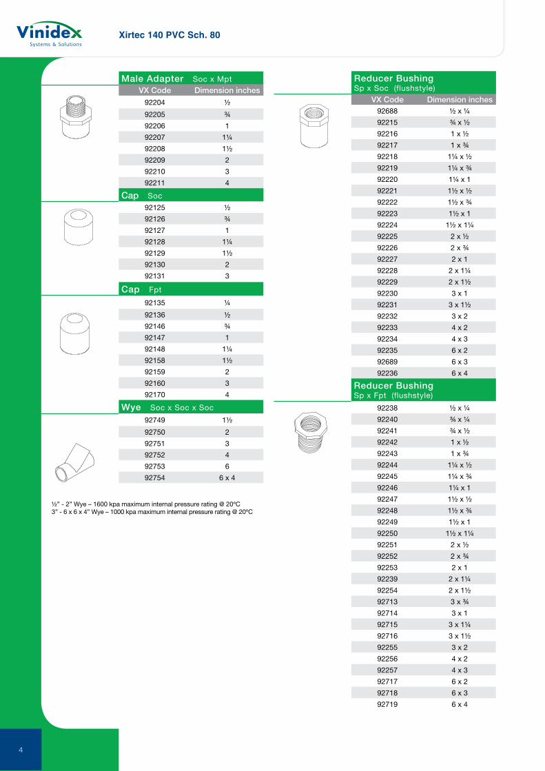
92204 ½
92205 ¾
92206 1
92207 1¼
92208 1½
92209 2
92210 3
92211 4
Male Adapter Soc x MptVX Code Dimension inches
VX Code Dimension inches
½” - 2” Wye – 1600 kpa maximum internal pressure rating @ 20ºC3” - 6 x 6 x 4” Wye – 1000 kpa maximum internal pressure rating @ 20ºC
92135 ¼
92136 ½
92146 ¾
92147 1
92148 1¼
92158 1½
92159 2
92160 3
92170 4
92749 1½
92750 2
92751 3
92752 4
92753 6
92754 6 x 4
Cap Fpt
Wye Soc x Soc x Soc
Reducer Bushing Sp x Soc (flushstyle)
92688 ½ x ¼
92215 ¾ x ½
92216 1 x ½
92217 1 x ¾
92218 1¼ x ½
92219 1¼ x ¾
92220 1¼ x 1
92221 1½ x ½
92222 1½ x ¾
92223 1½ x 1
92224 1½ x 1¼
92225 2 x ½
92226 2 x ¾
92227 2 x 1
92228 2 x 1¼
92229 2 x 1½
92230 3 x 1
92231 3 x 1½
92232 3 x 2
92233 4 x 2
92234 4 x 3
92235 6 x 2
92689 6 x 3
92236 6 x 4
Reducer BushingSp x Fpt (flushstyle)
92238 ½ x ¼
92240 ¾ x ¼
92241 ¾ x ½
92242 1 x ½
92243 1 x ¾
92244 1¼ x ½
92245 1¼ x ¾
92246 1¼ x 1
92247 1½ x ½
92248 1½ x ¾
92249 1½ x 1
92250 1½ x 1¼
92251 2 x ½
92252 2 x ¾
92253 2 x 1
92239 2 x 1¼
92254 2 x 1½
92713 3 x ¾
92714 3 x 1
92715 3 x 1¼
92716 3 x 1½
92255 3 x 2
92256 4 x 2
92257 4 x 3
92717 6 x 2
92718 6 x 3
92719 6 x 4
Cap Soc
92125 ½
92126 ¾
92127 1
92128 1¼
92129 1½
92130 2
92131 3
4
Xirtec 140 PVC Sch. 80
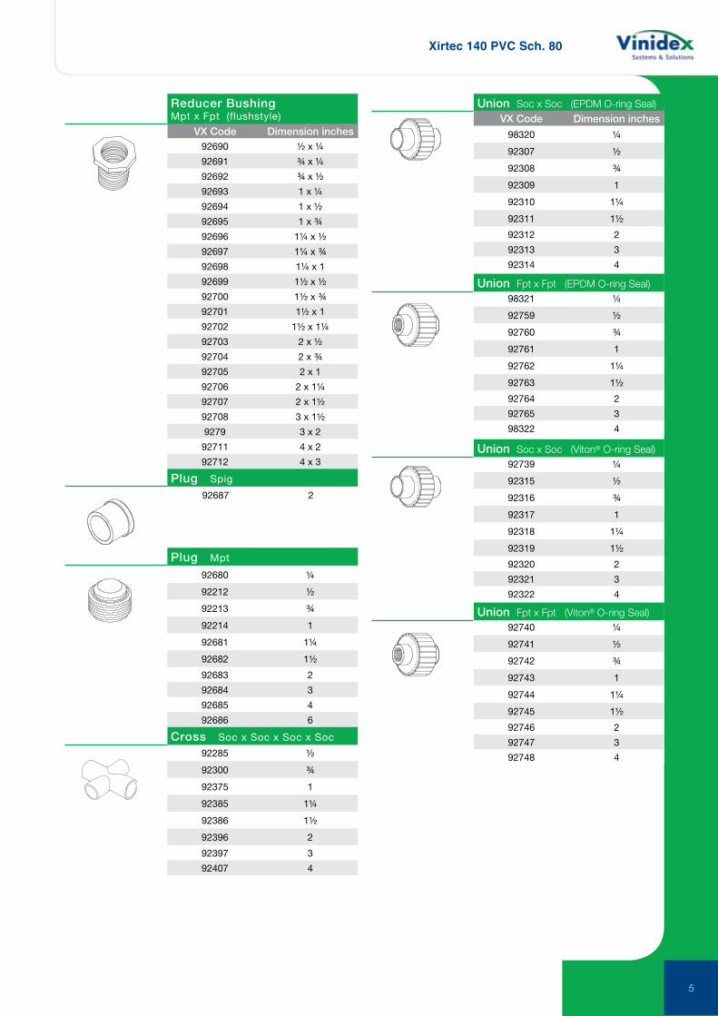
VX Code Dimension inches
Reducer BushingMpt x Fpt (flushstyle)
92690 ½ x ¼
92691 ¾ x ¼
92692 ¾ x ½
92693 1 x ¼
92694 1 x ½
92695 1 x ¾
92696 1¼ x ½
92697 1¼ x ¾
92698 1¼ x 1
92699 1½ x ½
92700 1½ x ¾
92701 1½ x 1
92702 1½ x 1¼
92703 2 x ½
92704 2 x ¾
92705 2 x 1
92706 2 x 1¼
92707 2 x 1½
92708 3 x 1½
9279 3 x 2
92711 4 x 2
92712 4 x 3
92687 2
Plug Spig
92680 ¼
92212 ½
92213 ¾
92214 1
92681 1¼
92682 1½
92683 2
92684 3
92685 4
92686 6
92285 ½
92300 ¾
92375 1
92385 1¼
92386 1½
92396 2
92397 3
92407 4
Plug Mpt
Cross Soc x Soc x Soc x Soc
98320 ¼
92307 ½
92308 ¾
92309 1
92310 1¼
92311 1½
92312 2
92313 3
92314 4
98321 ¼
92759 ½
92760 ¾
92761 1
92762 1¼
92763 1½
92764 2
92765 3
98322 4
92739 ¼
92315 ½
92316 ¾
92317 1
92318 1¼
92319 1½
92320 2
92321 3
92322 4
92740 ¼
92741 ½
92742 ¾
92743 1
92744 1¼
92745 1½
92746 2
92747 3
92748 4
Union Soc x Soc (EPDM O-ring Seal)
Union Fpt x Fpt (EPDM O-ring Seal)
Union Soc x Soc (Viton® O-ring Seal)
Union Fpt x Fpt (Viton® O-ring Seal)
VX Code Dimension inches
5
Xirtec 140 PVC Sch. 80
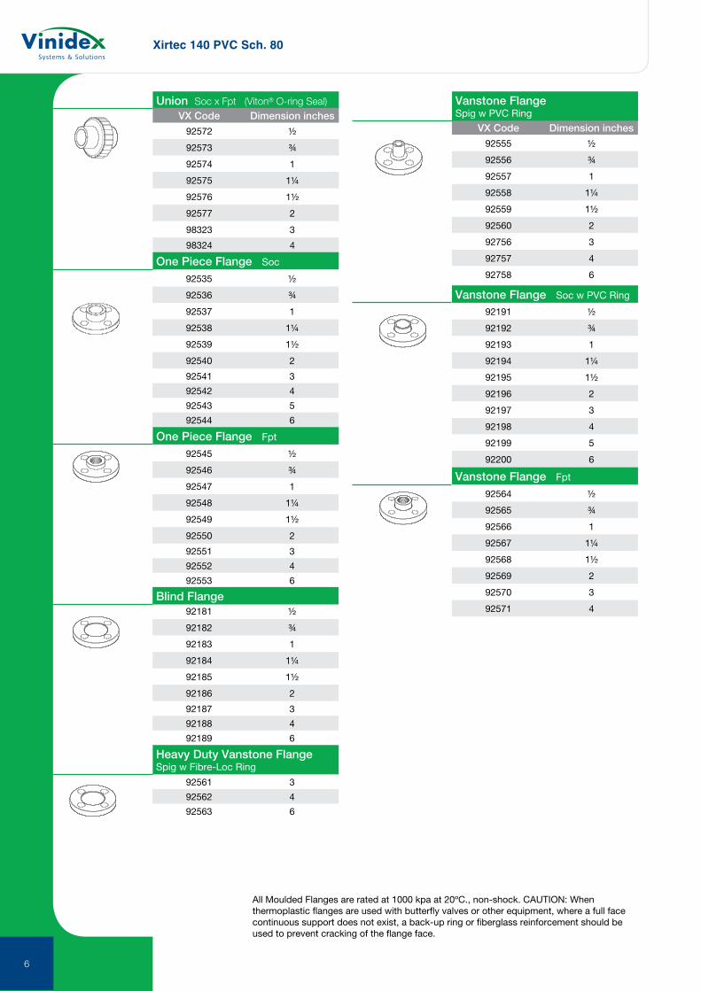
92572 ½
92573 ¾
92574 1
92575 1¼
92576 1½
92577 2
98323 3
98324 4
92535 ½
92536 ¾
92537 1
92538 1¼
92539 1½
92540 2
92541 3
92542 4
92543 5
92544 6
92545 ½
92546 ¾
92547 1
92548 1¼
92549 1½
92550 2
92551 3
92552 4
92553 6
92181 ½
92182 ¾
92183 1
92184 1¼
92185 1½
92186 2
92187 3
92188 4
92189 6
Union Soc x Fpt (Viton® O-ring Seal)
One Piece Flange Soc
One Piece Flange Fpt
Blind Flange
VX Code Dimension inchesVX Code Dimension inches
92561 3
92562 4
92563 6
92555 ½
92556 ¾
92557 1
92558 1¼
92559 1½
92560 2
92756 3
92757 4
92758 6
Heavy Duty Vanstone Flange Spig w Fibre-Loc Ring
Vanstone Flange Spig w PVC Ring
92191 ½
92192 ¾
92193 1
92194 1¼
92195 1½
92196 2
92197 3
92198 4
92199 5
92200 6
92564 ½
92565 ¾
92566 1
92567 1¼
92568 1½
92569 2
92570 3
92571 4
Vanstone Flange Soc w PVC Ring
Vanstone Flange Fpt
All Moulded Flanges are rated at 1000 kpa at 20ºC., non-shock. CAUTION: When thermoplastic flanges are used with butterfly valves or other equipment, where a full face continuous support does not exist, a back-up ring or fiberglass reinforcement should be used to prevent cracking of the flange face.
6
Xirtec 140 PVC Sch. 80
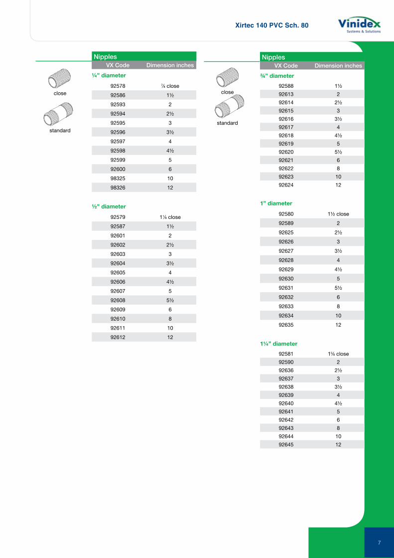
NipplesVX Code Dimension inches
¼” diameter
92578 7⁄8 close
92586 1½
92593 2
92594 2½
92595 3
92596 3½
92597 4
92598 4½
92599 5
92600 6
98325 10
98326 12
½” diameter
92579 11⁄8 close
92587 1½
92601 2
92602 2½
92603 3
92604 3½
92605 4
92606 4½
92607 5
92608 5½
92609 6
92610 8
92611 10
92612 12
close
standard
close
standard
¾” diameter
92588 1½
92613 2
92614 2½
92615 3
92616 3½
92617 4
92618 4½
92619 5
92620 5½
92621 6
92622 8
92623 10
92624 12
1” diameter
92580 1½ close
92589 2
92625 2½
92626 3
92627 3½
92628 4
92629 4½
92630 5
92631 5½
92632 6
92633 8
92634 10
92635 12
1¼” diameter
92581 15⁄8 close
92590 2
92636 2½
92637 3
92638 3½
92639 4
92640 4½
92641 5
92642 6
92643 8
92644 10
92645 12
NipplesVX Code Dimension inches
7
Xirtec 140 PVC Sch. 80
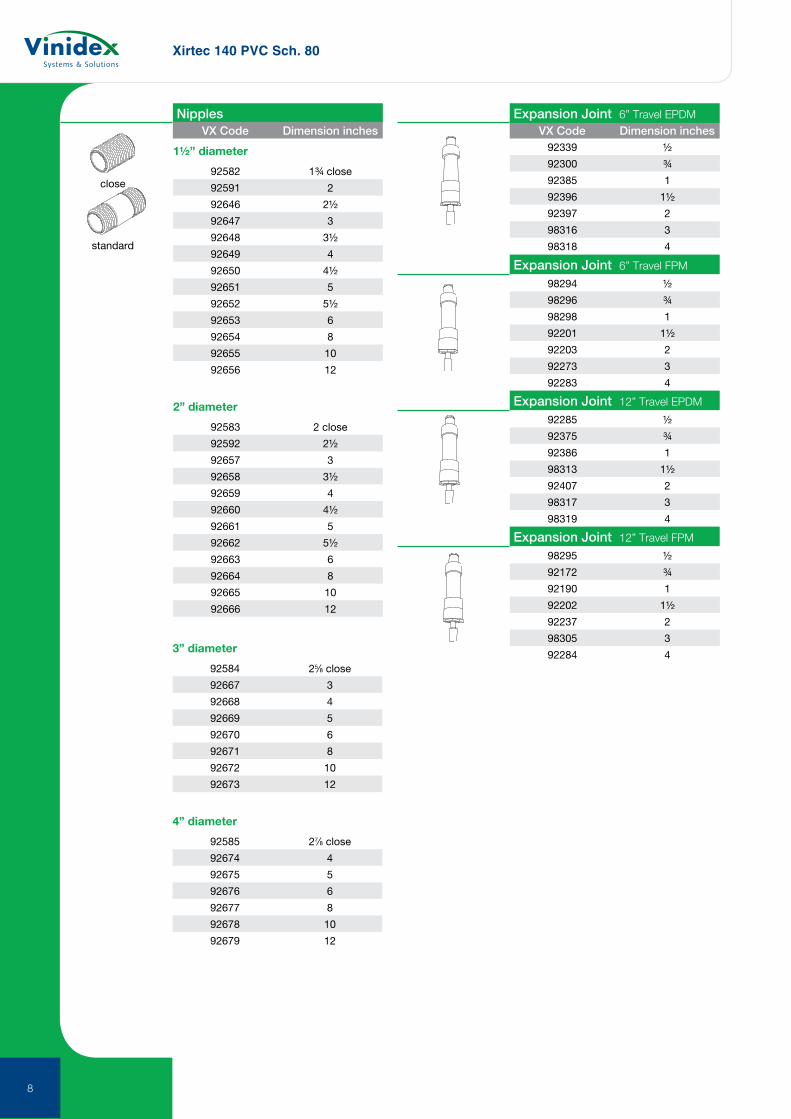
1½” diameter
92582 1¾ close
92591 2
92646 2½
92647 3
92648 3½
92649 4
92650 4½
92651 5
92652 5½
92653 6
92654 8
92655 10
92656 12
2” diameter
92583 2 close
92592 2½
92657 3
92658 3½
92659 4
92660 4½
92661 5
92662 5½
92663 6
92664 8
92665 10
92666 12
close
standard
NipplesVX Code Dimension inches VX Code Dimension inches
3” diameter
92584 25⁄8 close
92667 3
92668 4
92669 5
92670 6
92671 8
92672 10
92673 12
4” diameter
92585 27⁄8 close
92674 4
92675 5
92676 6
92677 8
92678 10
92679 12
Expansion Joint 6” Travel EPDM
Expansion Joint 6” Travel FPM
Expansion Joint 12” Travel EPDM
Expansion Joint 12” Travel FPM
92339 ½
92300 ¾
92385 1
92396 1½
92397 2
98316 3
98318 4
98294 ½
98296 ¾
98298 1
92201 1½
92203 2
92273 3
92283 4
92285 ½
92375 ¾
92386 1
98313 1½
92407 2
98317 3
98319 4
98295 ½
92172 ¾
92190 1
92202 1½
92237 2
98305 3
92284 4
8
Corzan CPVC Sch. 80
9
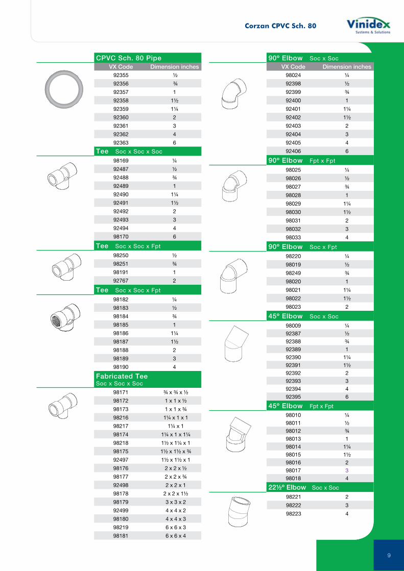
VX Code Dimension inches
Fabricated Tee Soc x Soc x Soc
Tee Soc x Soc x Soc
Tee Soc x Soc x Fpt
Tee Soc x Soc x Fpt
98169 ¼
92487 ½
92488 ¾
92489 1
92490 1¼
92491 1½
92492 2
92493 3
92494 4
98170 6
98250 ½
98251 ¾
98191 1
92767 2
98182 ¼
98183 ½
98184 ¾
98185 1
98186 1¼
98187 1½
98188 2
98189 3
98190 4
98171 ¾ x ¾ x ½
98172 1 x 1 x ½
98173 1 x 1 x ¾
98216 1¼ x 1 x 1
98217 1¼ x 1
98174 1¼ x 1 x 1¼
98218 1½ x 1¼ x 1
98175 1½ x 1½ x ¾
92497 1½ x 1½ x 1
98176 2 x 2 x ½
98177 2 x 2 x ¾
92498 2 x 2 x 1
98178 2 x 2 x 1½
98179 3 x 3 x 2
92499 4 x 4 x 2
98180 4 x 4 x 3
98219 6 x 6 x 3
98181 6 x 6 x 4
98024 ¼
92398 ½
92399 ¾
92400 1
92401 1¼
92402 1½
92403 2
92404 3
92405 4
92406 6
98025 ¼
98026 ½
98027 ¾
98028 1
98029 1¼
98030 1½
98031 2
98032 3
98033 4
98220 ¼
98019 ½
98249 ¾
98020 1
98021 1¼
98022 1½
98023 2
90º Elbow Soc x Soc
90º Elbow Fpt x Fpt
90º Elbow Soc x Fpt
VX Code Dimension inches
45º Elbow Soc x Soc
45º Elbow Fpt x Fpt
22½º Elbow Soc x Soc
98009 ¼92387 ½92388 ¾92389 192390 1¼92391 1½92392 292393 392394 492395 6
98010 ¼98011 ½98012 ¾98013 198014 1¼98015 1½98016 298017 398018 4
98221 2
98222 3
98223 4
92355 ½
92356 ¾
92357 1
92358 1½
92359 1¼
92360 2
92361 3
92362 4
92363 6
CPVC Sch. 80 Pipe
Corzan CPVC Sch. 80
10
92778 ¼
92376 ½
92377 ¾
92378 1
92379 1¼
92380 1½
92381 2
92382 3
92383 4
92384 6
92779 ¼
92780 ½
92781 ¾
92782 1
92783 1¼
92784 1½
92785 2
92786 3
92787 4
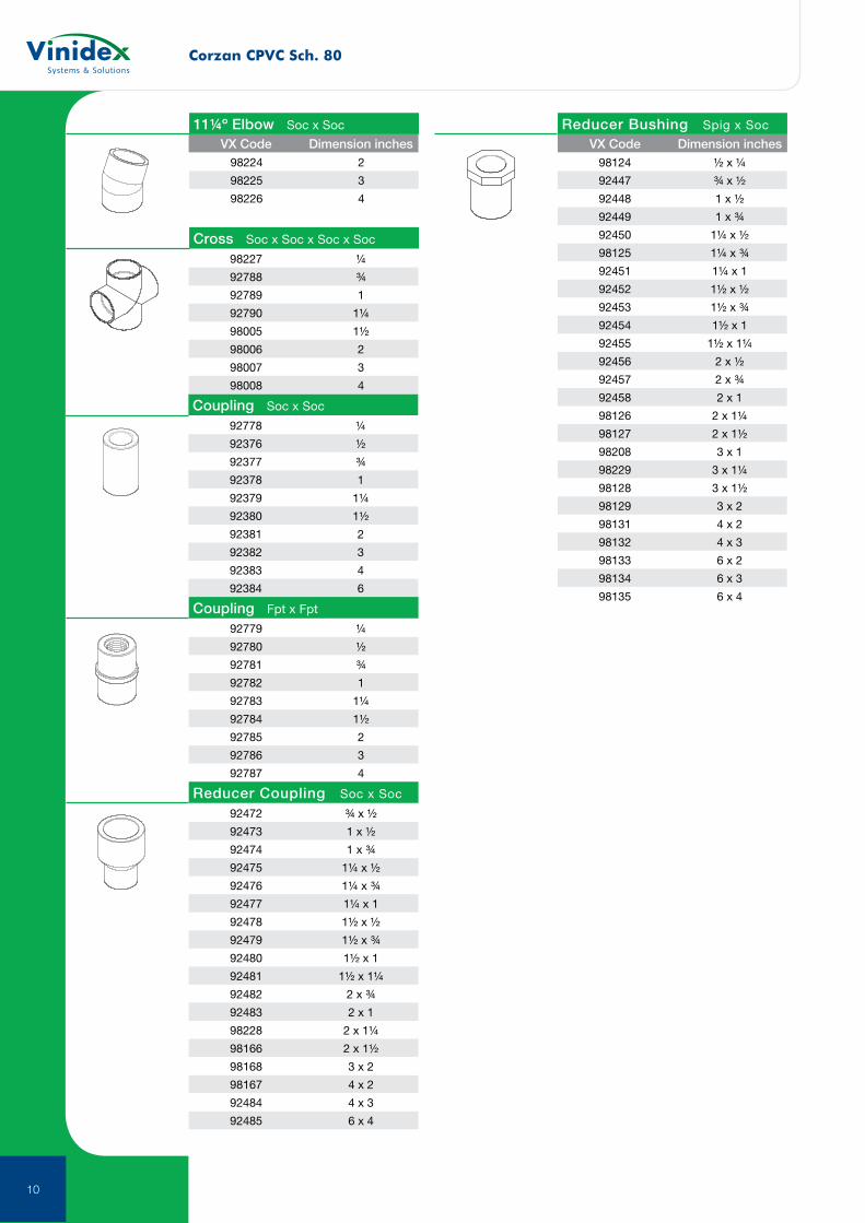
Coupling Soc x Soc
VX Code Dimension inches
Coupling Fpt x Fpt
Reducer Coupling Soc x Soc
92472 ¾ x ½
92473 1 x ½
92474 1 x ¾
92475 1¼ x ½
92476 1¼ x ¾
92477 1¼ x 1
92478 1½ x ½
92479 1½ x ¾
92480 1½ x 1
92481 1½ x 1¼
92482 2 x ¾
92483 2 x 1
98228 2 x 1¼
98166 2 x 1½
98168 3 x 2
98167 4 x 2
92484 4 x 3
92485 6 x 4
VX Code Dimension inches
Reducer Bushing Spig x Soc
98124 ½ x ¼
92447 ¾ x ½
92448 1 x ½
92449 1 x ¾
92450 1¼ x ½
98125 1¼ x ¾
92451 1¼ x 1
92452 1½ x ½
92453 1½ x ¾
92454 1½ x 1
92455 1½ x 1¼
92456 2 x ½
92457 2 x ¾
92458 2 x 1
98126 2 x 1¼
98127 2 x 1½
98208 3 x 1
98229 3 x 1¼
98128 3 x 1½
98129 3 x 2
98131 4 x 2
98132 4 x 3
98133 6 x 2
98134 6 x 3
98135 6 x 4
11¼º Elbow Soc x Soc
Cross Soc x Soc x Soc x Soc
98224 2
98225 3
98226 4
98227 ¼
92788 ¾
92789 1
92790 1¼
98005 1½
98006 2
98007 3
98008 4
Corzan CPVC Sch. 80
11
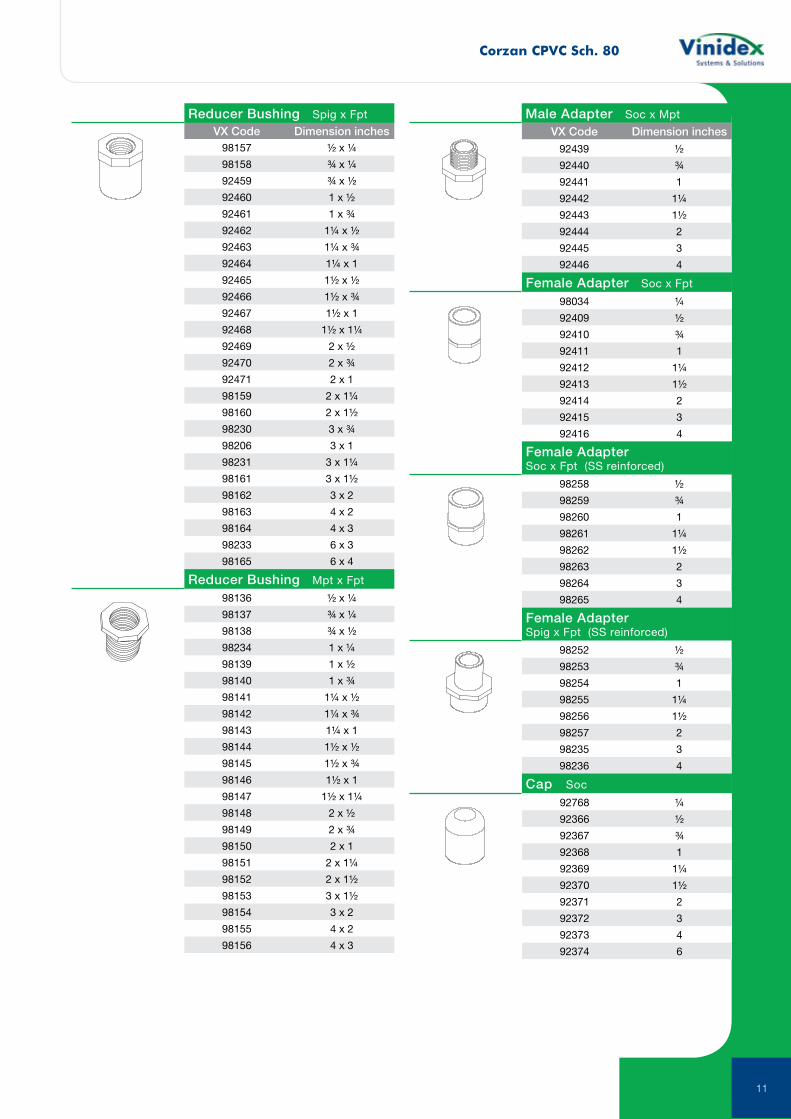
98157 ½ x ¼
98158 ¾ x ¼
92459 ¾ x ½
92460 1 x ½
92461 1 x ¾
92462 1¼ x ½
92463 1¼ x ¾
92464 1¼ x 1
92465 1½ x ½
92466 1½ x ¾
92467 1½ x 1
92468 1½ x 1¼
92469 2 x ½
92470 2 x ¾
92471 2 x 1
98159 2 x 1¼
98160 2 x 1½
98230 3 x ¾
98206 3 x 1
98231 3 x 1¼
98161 3 x 1½
98162 3 x 2
98163 4 x 2
98164 4 x 3
98233 6 x 3
98165 6 x 4
VX Code Dimension inchesReducer Bushing Spig x Fpt
Reducer Bushing Mpt x Fpt
98136 ½ x ¼
98137 ¾ x ¼
98138 ¾ x ½
98234 1 x ¼
98139 1 x ½
98140 1 x ¾
98141 1¼ x ½
98142 1¼ x ¾
98143 1¼ x 1
98144 1½ x ½
98145 1½ x ¾
98146 1½ x 1
98147 1½ x 1¼
98148 2 x ½
98149 2 x ¾
98150 2 x 1
98151 2 x 1¼
98152 2 x 1½
98153 3 x 1½
98154 3 x 2
98155 4 x 2
98156 4 x 3
Male Adapter Soc x Mpt
92439 ½
92440 ¾
92441 1
92442 1¼
92443 1½
92444 2
92445 3
92446 4
VX Code Dimension inches
Female Adapter Soc x Fpt
98034 ¼
92409 ½
92410 ¾
92411 1
92412 1¼
92413 1½
92414 2
92415 3
92416 4
Female AdapterSoc x Fpt (SS reinforced)
Female AdapterSpig x Fpt (SS reinforced)
98258 ½
98259 ¾
98260 1
98261 1¼
98262 1½
98263 2
98264 3
98265 4
98252 ½
98253 ¾
98254 1
98255 1¼
98256 1½
98257 2
98235 3
98236 4
92768 ¼
92366 ½
92367 ¾
92368 1
92369 1¼
92370 1½
92371 2
92372 3
92373 4
92374 6
Cap Soc
Corzan CPVC Sch. 80
12
All Moulded Flanges are rated at 1000 kpa at 20ºC., non-shock. CAUTION: When thermoplastic flanges are used with butterfly valves or other equipment, where a full face continuous support does not exist, a back-up ring or fiberglass reinforcement should be used to prevent cracking of the flange face.
92769 ¼
92770 ½
92771 ¾
92772 1
92773 1¼
92774 1½
92775 2
92776 3
92777 4
VX Code Dimension inches VX Code Dimension inches
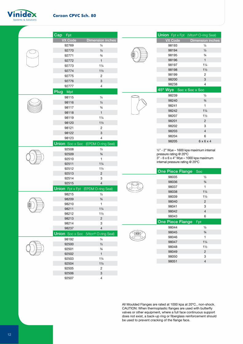
Union Fpt x Fpt (EPDM O-ring Seal)
Union Soc x Soc (Viton® O-ring Seal)
Union Fpt x Fpt (Viton® O-ring Seal)
45º Wye Soc x Soc x Soc
Cap Fpt
Plug Mpt
Union Soc x Soc (EPDM O-ring Seal)
98115 ¼
98116 ½
98117 ¾
98118 1
98119 1¼
98120 1½
98121 2
98122 3
98123 4
92508 ½
92509 ¾
92510 1
92511 1¼
92512 1½
92513 2
92514 3
92515 4
98215 ½
98209 ¾
98210 1
98211 1¼
98212 1½
98213 2
98214 3
98237 4
98192 ¼
92500 ½
92501 ¾
92502 1
92503 1¼
92504 1½
92505 2
92506 3
92507 4
98193 ¼
98194 ½
98195 ¾
98196 1
98197 1¼
98198 1½
98199 2
98200 3
98238 4
98239 ½
98240 ¾
98241 1
98242 1¼
98207 1½
98201 2
98202 3
98203 4
98204 6
98205 6 x 6 x 4
½” - 2” Wye – 1600 kpa maximum internal pressure rating @ 20ºC3” - 6 x 6 x 4” Wye – 1000 kpa maximum internal pressure rating @ 20ºC
One Piece Flange Soc
One Piece Flange Fpt
98035 ½
98036 ¾
98037 1
98038 1¼
98039 1½
98040 2
98041 3
98042 4
98043 6
98044 ½
98045 ¾
98046 1
98047 1¼
98048 1½
98049 2
98050 3
98051 4
Corzan CPVC Sch. 80
13
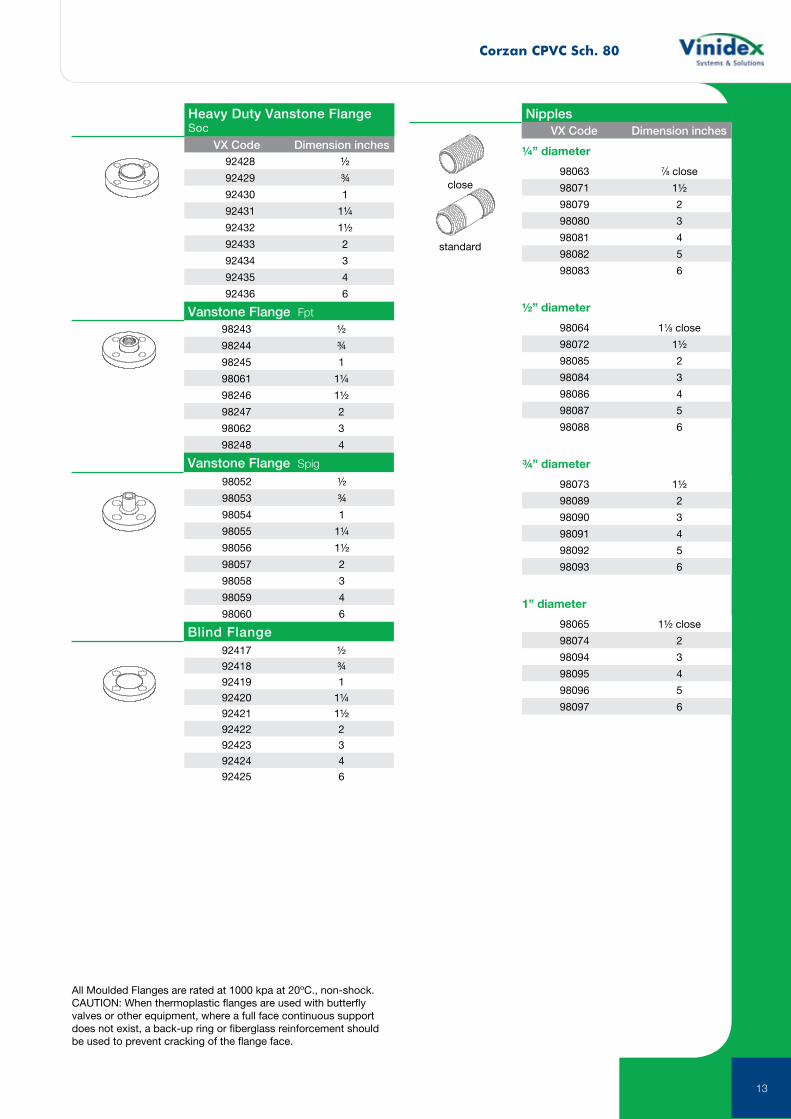
All Moulded Flanges are rated at 1000 kpa at 20ºC., non-shock. CAUTION: When thermoplastic flanges are used with butterfly valves or other equipment, where a full face continuous support does not exist, a back-up ring or fiberglass reinforcement should be used to prevent cracking of the flange face.
VX Code Dimension inches
Vanstone Flange Fpt
Heavy Duty Vanstone Flange Soc
92428 ½
92429 ¾
92430 1
92431 1¼
92432 1½
92433 2
92434 3
92435 4
92436 6
98243 ½
98244 ¾
98245 1
98061 1¼
98246 1½
98247 2
98062 3
98248 4
92417 ½
92418 ¾
92419 1
92420 1¼
92421 1½
92422 2
92423 3
92424 4
92425 6
98052 ½
98053 ¾
98054 1
98055 1¼
98056 1½
98057 2
98058 3
98059 4
98060 6
close
standard
Vanstone Flange Spig
Blind Flange
¼” diameter
98063 7⁄8 close
98071 1½
98079 2
98080 3
98081 4
98082 5
98083 6
½” diameter
98064 11⁄8 close
98072 1½
98085 2
98084 3
98086 4
98087 5
98088 6
¾” diameter
98073 1½
98089 2
98090 3
98091 4
98092 5
98093 6
1” diameter
98065 1½ close
98074 2
98094 3
98095 4
98096 5
98097 6
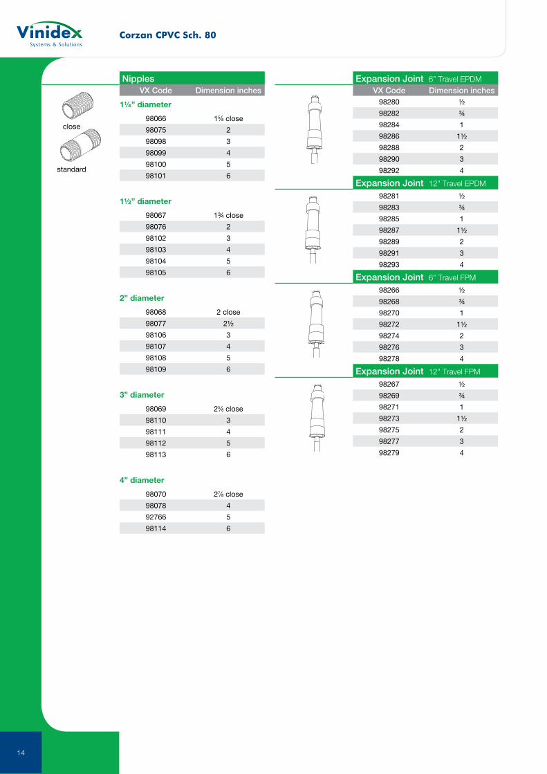
NipplesVX Code Dimension inches
Corzan CPVC Sch. 80
14
close
standard
1¼” diameter
98066 15⁄8 close
98075 2
98098 3
98099 4
98100 5
98101 6
1½” diameter
98067 1¾ close
98076 2
98102 3
98103 4
98104 5
98105 6
2” diameter
98068 2 close
98077 2½
98106 3
98107 4
98108 5
98109 6
3” diameter
98069 25⁄8 close
98110 3
98111 4
98112 5
98113 6
4” diameter
98070 27⁄8 close
98078 4
92766 5
98114 6
Nipples Expansion Joint 6” Travel EPDM
Expansion Joint 12” Travel EPDM
Expansion Joint 6” Travel FPM
Expansion Joint 12” Travel FPM
VX Code Dimension inches VX Code Dimension inches98280 ½
98282 ¾
98284 1
98286 1½
98288 2
98290 3
98292 4
98281 ½
98283 ¾
98285 1
98287 1½
98289 2
98291 3
98293 4
98266 ½
98268 ¾
98270 1
98272 1½
98274 2
98276 3
98278 4
98267 ½
98269 ¾
98271 1
98273 1½
98275 2
98277 3
98279 4

15
SuperFLO ABS
16
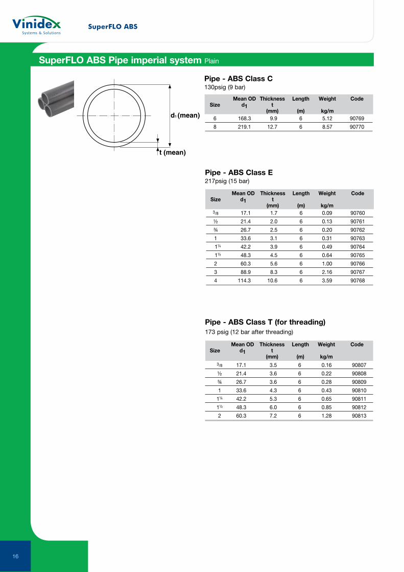
SuperFLO ABS Pipe imperial system Plain
d1 (mean)
t (mean)
Mean OD Thickness Length Weight Code Size d1 t (mm) (m) kg/m 3/8 17.1 1.7 6 0.09 90760
½ 21.4 2.0 6 0.13 90761
¾ 26.7 2.5 6 0.20 90762
1 33.6 3.1 6 0.31 90763
1¼ 42.2 3.9 6 0.49 90764
1½ 48.3 4.5 6 0.64 90765
2 60.3 5.6 6 1.00 90766
3 88.9 8.3 6 2.16 90767
4 114.3 10.6 6 3.59 90768
Mean OD Thickness Length Weight Code Size d1 t (mm) (m) kg/m 6 168.3 9.9 6 5.12 90769
8 219.1 12.7 6 8.57 90770
Mean OD Thickness Length Weight Code Size d1 t (mm) (m) kg/m
3/8 17.1 3.5 6 0.16 90807
½ 21.4 3.6 6 0.22 90808
¾ 26.7 3.6 6 0.28 90809
1 33.6 4.3 6 0.43 90810
1¼ 42.2 5.3 6 0.65 90811
1½ 48.3 6.0 6 0.85 90812
2 60.3 7.2 6 1.28 90813
Pipe - ABS Class T (for threading) 173 psig (12 bar after threading)
Pipe - ABS Class E 217psig (15 bar)
Pipe - ABS Class C130psig (9 bar)
SuperFLO ABS
17
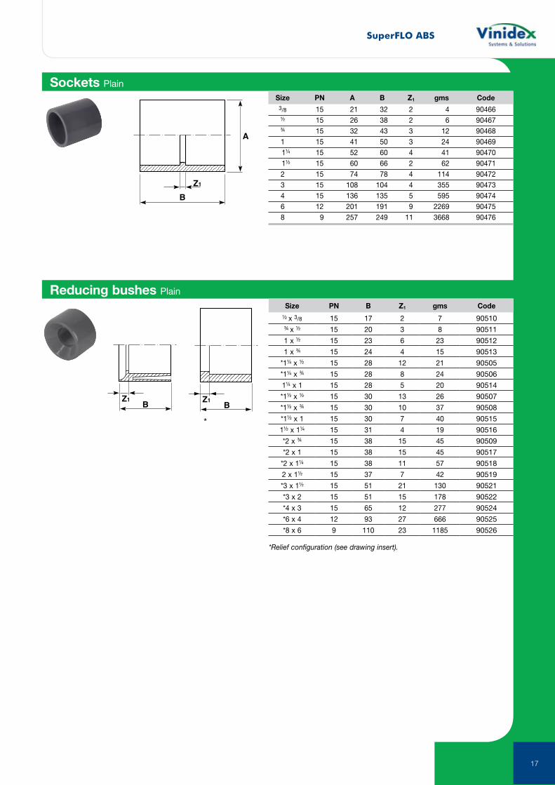
Sockets Plain
B
Z1
A
Size PN A B Z1 gms Code
3/8 15 21 32 2 4 90466 ½ 15 26 38 2 6 90467 ¾ 15 32 43 3 12 90468 1 15 41 50 3 24 90469 1¼ 15 52 60 4 41 90470 1½ 15 60 66 2 62 90471 2 15 74 78 4 114 90472 3 15 108 104 4 355 90473 4 15 136 135 5 595 90474 6 12 201 191 9 2269 90475 8 9 257 249 11 3668 90476
Reducing bushes Plain
BZ1
Size PN B Z1 gms Code½ x 3/8 15 17 2 7 90510¾ x ½ 15 20 3 8 90511
1 x ½ 15 23 6 23 90512
1 x ¾ 15 24 4 15 90513
*1¼ x ½ 15 28 12 21 90505
*1¼ x ¾ 15 28 8 24 90506
1¼ x 1 15 28 5 20 90514
*1½ x ½ 15 30 13 26 90507
*1½ x ¾ 15 30 10 37 90508
*1½ x 1 15 30 7 40 90515
1½ x 1¼ 15 31 4 19 90516
*2 x ¾ 15 38 15 45 90509
*2 x 1 15 38 15 45 90517
*2 x 1¼ 15 38 11 57 90518
2 x 1½ 15 37 7 42 90519
*3 x 1½ 15 51 21 130 90521
*3 x 2 15 51 15 178 90522
*4 x 3 15 65 12 277 90524
*6 x 4 12 93 27 666 90525
*8 x 6 9 110 23 1185 90526
*Relief configuration (see drawing insert).
BZ1
BZ1
*
SuperFLO ABS
18
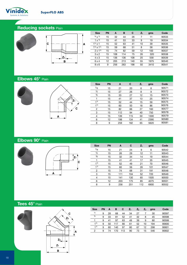
Elbows 45° Plain
Elbows 90° Plain
Z1
A
C
Size PN A C Z1 gms Code
3/8 15 21 20 6 8 90571
½ 15 27 26 8 9 90572
¾ 15 33 27 12 15 90573
1 15 41 37 13 25 90574
1¼ 15 52 44 15 59 90575
1½ 15 60 50 18 86 90576
2 15 82 66 27 160 90577
3 15 112 94 40 750 90578
4 15 139 115 50 1300 90579
6 12 198 134 41 2390 90580
8 9 259 182 65 5620 90581
Size PN A C Z1 gms Code
3/8 15 21 24 9 6 90542 ½ 15 26 29 12 11 90543 ¾ 15 32 34 14 19 90544 1 15 41 41 17 35 90545 1¼ 15 52 49 21 70 90546 1½ 15 60 56 26 101 90547 2 15 74 68 31 191 90548 3 15 111 104 52 720 90549 4 15 141 130 65 1505 90550 6 12 203 175 85 4075 90551 8 9 256 251 112 6900 90552
A
Z1
C
B
A
Z1
C
Reducing sockets Plain Size PN A B C Z1 gms Code
¾ x ½ 15 32 44 26 7 11 90533 1 x ¾ 15 41 53 33 9 19 90534 1¼ x 1 15 52 63 41 10 39 90535 1½ x 1¼ 15 59 68 51 8 58 90536 2 x 1½ 15 74 82 59 12 100 90537 3 x 2 15 108 114 75 26 320 90538 4 x 3 15 136 136 108 20 558 90539 6 x 4 12 205 213 140 55 1975 90540 8 x 6 9 256 263 198 50 3410 90541
B
A
Z1
Z3
C
Z2
Tees 45° Plain
Size PN A B C Z1 Z2 Z3 gms Code
½ 9 28 68 44 34 27 7 30 90597 ¾ 9 33 81 52 41 32 8 45 90598 1 9 41 97 63 49 39 9 80 90599 1¼ 9 50 117 80 61 52 10 194 90600 1½ 9 60 140 97 80 67 12 298 90601 2 9 74 170 113 90 73 15 546 90602
SuperFLO ABS
19
C
Z1
BAZ1
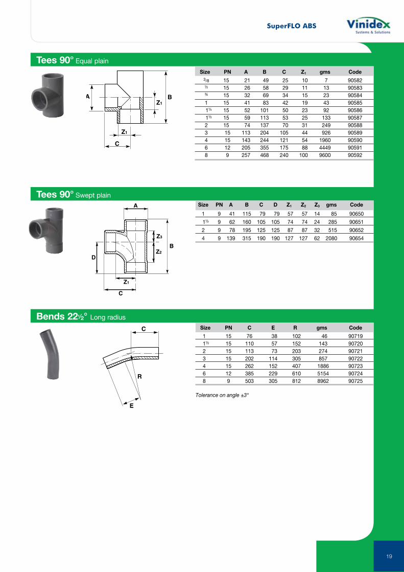
Tees 90° Equal plain
Size PN A B C Z1 gms Code
3/8 15 21 49 25 10 7 90582 ½ 15 26 58 29 11 13 90583 ¾ 15 32 69 34 15 23 90584 1 15 41 83 42 19 43 90585 1¼ 15 52 101 50 23 92 90586 1½ 15 59 113 53 25 133 90587 2 15 74 137 70 31 249 90588 3 15 113 204 105 44 926 90589 4 15 143 244 121 54 1960 90590 6 12 205 355 175 88 4449 90591 8 9 257 468 240 100 9600 90592
C
Z1
D
A
Z3
Z2B
Tees 90° Swept plain Size PN A B C D Z1 Z2 Z3 gms Code
1 9 41 115 79 79 57 57 14 85 90650
1½ 9 62 160 105 105 74 74 24 285 90651
2 9 78 195 125 125 87 87 32 515 90652
4 9 139 315 190 190 127 127 62 2080 90654
Bends 221⁄2° Long radius
Size PN C E R gms Code
1 15 76 38 102 46 90719 1½ 15 110 57 152 143 90720 2 15 113 73 203 274 90721 3 15 202 114 305 857 90722 4 15 262 152 407 1886 90723 6 12 385 229 610 5154 90724 8 9 503 305 812 8962 90725
Tolerance on angle ±3°
R
C
E
SuperFLO ABS
20
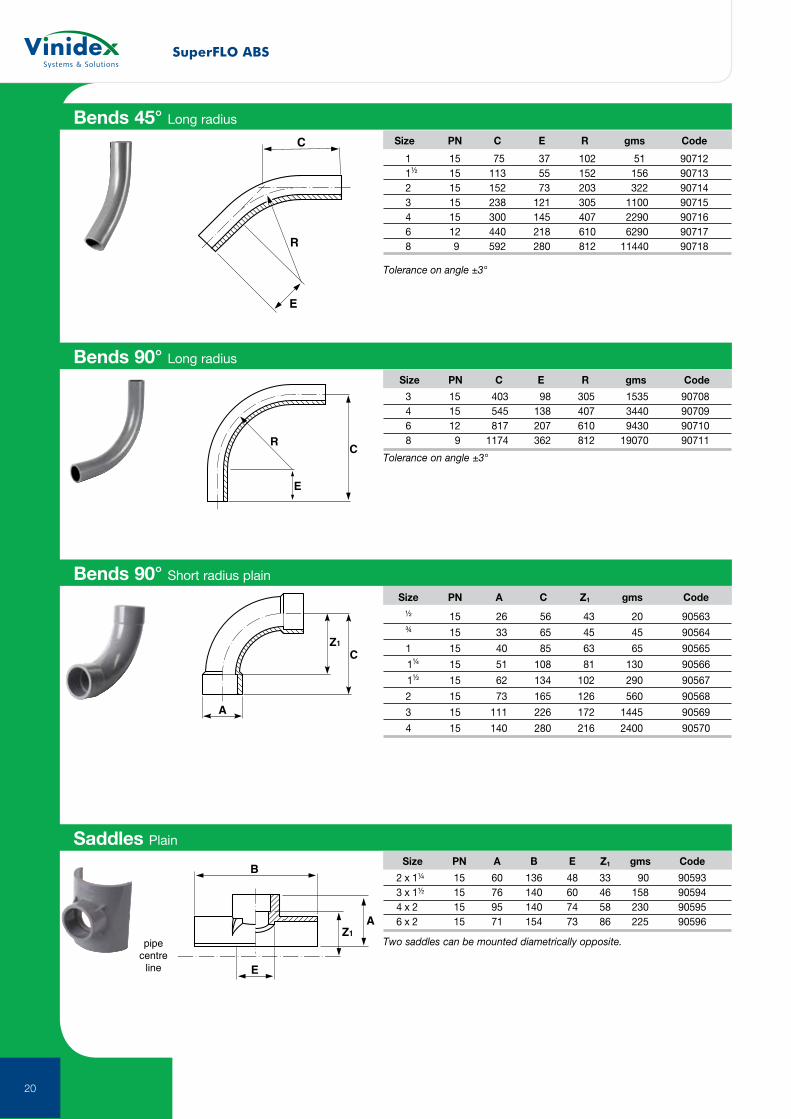
Bends 45° Long radius
C
R
E
Size PN C E R gms Code
1 15 75 37 102 51 90712 1½ 15 113 55 152 156 90713 2 15 152 73 203 322 90714 3 15 238 121 305 1100 90715 4 15 300 145 407 2290 90716 6 12 440 218 610 6290 90717 8 9 592 280 812 11440 90718
Tolerance on angle ±3°
Bends 90° Long radius
CR
E
Size PN C E R gms Code
3 15 403 98 305 1535 90708 4 15 545 138 407 3440 90709 6 12 817 207 610 9430 90710 8 9 1174 362 812 19070 90711
Tolerance on angle ±3°
Bends 90° Short radius plain
Z1
C
A
Size PN A C Z1 gms Code
½ 15 26 56 43 20 90563
¾ 15 33 65 45 45 90564
1 15 40 85 63 65 90565
1¼ 15 51 108 81 130 90566
1½ 15 62 134 102 290 90567
2 15 73 165 126 560 90568
3 15 111 226 172 1445 90569
4 15 140 280 216 2400 90570
B
E
AZ1
pipecentre
line
Saddles Plain
Size PN A B E Z1 gms Code
2 x 1¼ 15 60 136 48 33 90 90593 3 x 1½ 15 76 140 60 46 158 90594 4 x 2 15 95 140 74 58 230 90595 6 x 2 15 71 154 73 86 225 90596
Two saddles can be mounted diametrically opposite.
SuperFLO ABS
21
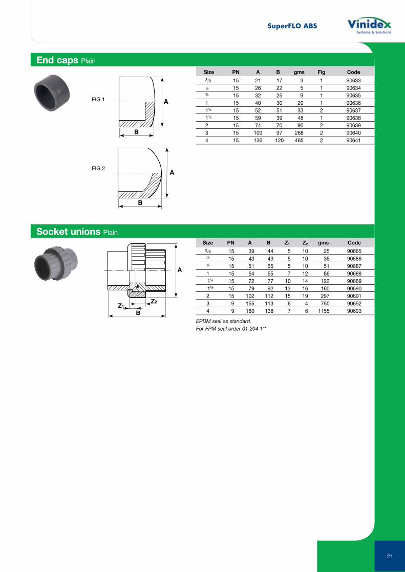
End caps Plain
Socket unions Plain
B
Z2Z1
A
Size PN A B gms Fig Code
3/8 15 21 17 3 1 90633 ½ 15 26 22 5 1 90634 ¾ 15 32 25 9 1 90635 1 15 40 30 20 1 90636 1¼ 15 52 51 33 2 90637 1½ 15 59 39 48 1 90638 2 15 74 70 90 2 90639 3 15 109 97 268 2 90640 4 15 136 120 465 2 90641
Size PN A B Z1 Z2 gms Code
3/8 15 39 44 5 10 25 90685 ½ 15 43 49 5 10 36 90686 ¾ 15 51 55 5 10 51 90687 1 15 64 65 7 12 86 90688 1¼ 15 72 77 10 14 122 90689 1½ 15 79 92 13 16 160 90690 2 15 102 112 15 19 297 90691 3 9 155 113 6 4 750 90692 4 9 180 138 7 6 1155 90693
EPDM seal as standard.For FPM seal order 01 204 1**
FIG.1
FIG.2
B
A
B
A
SuperFLO ABS
22
BZ1
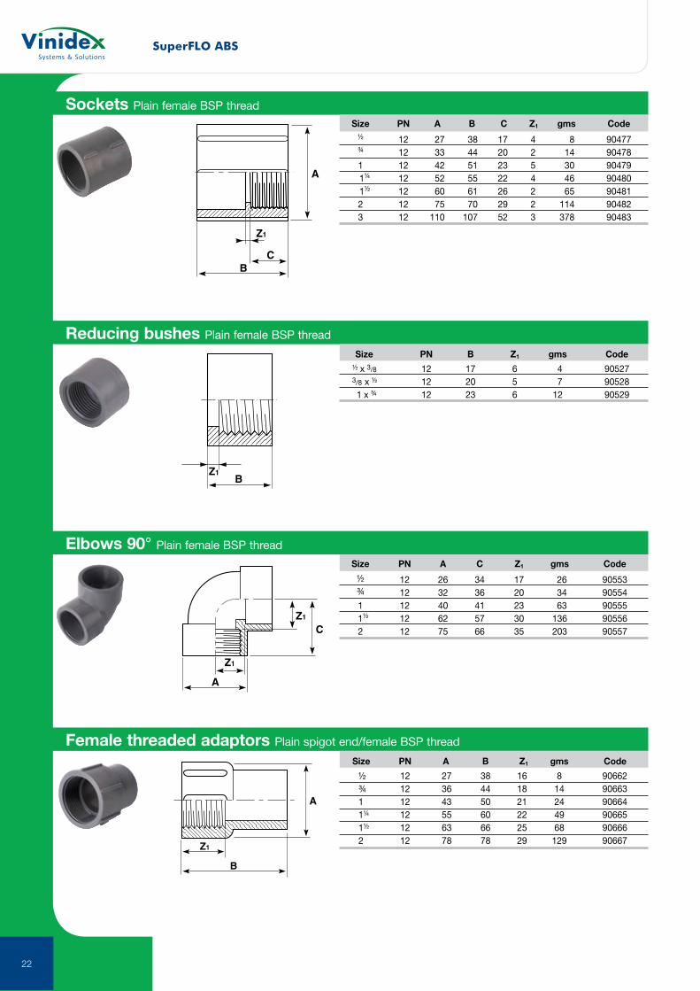
Reducing bushes Plain female BSP thread
Size PN B Z1 gms Code
½ x 3/8 12 17 6 4 90527 3/8 x ½ 12 20 5 7 90528 1 x ¾ 12 23 6 12 90529
A
Z1
C
Z1
Elbows 90° Plain female BSP thread
Size PN A C Z1 gms Code
½ 12 26 34 17 26 90553 ¾ 12 32 36 20 34 90554 1 12 40 41 23 63 90555 1½ 12 62 57 30 136 90556 2 12 75 66 35 203 90557
BC
Z1
A
Sockets Plain female BSP thread
Size PN A B C Z1 gms Code
½ 12 27 38 17 4 8 90477 ¾ 12 33 44 20 2 14 90478 1 12 42 51 23 5 30 90479 1¼ 12 52 55 22 4 46 90480 1½ 12 60 61 26 2 65 90481 2 12 75 70 29 2 114 90482 3 12 110 107 52 3 378 90483
Female threaded adaptors Plain spigot end/female BSP thread
Size PN A B Z1 gms Code
½ 12 27 38 16 8 90662 ¾ 12 36 44 18 14 90663 1 12 43 50 21 24 90664 1¼ 12 55 60 22 49 90665 1½ 12 63 66 25 68 90666 2 12 78 78 29 129 90667Z1
B
A
SuperFLO ABS
23
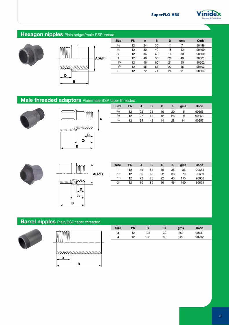
Hexagon nipples Plain spigot/male BSP thread Size PN A B D gms Code
3/8 12 24 36 11 7 90498 ½ 12 30 42 15 12 90499 ¾ 12 36 48 16 30 90500 1 12 46 56 20 40 90501 1¼ 12 46 60 21 50 90502 1½ 12 55 63 22 58 90503 2 12 72 74 26 91 90504
B
D
A(A/F)
Male threaded adaptors Plain/male BSP taper threaded Size PN A B D Z1 gms Code
3/8 12 22 35 10 20 5 90655 ½ 12 27 45 12 28 9 90656
¾ 12 35 48 14 28 14 90657
Z1
B
A
D
B
Z1
D
A(A/F)
Size PN A B D Z1 gms Code
1 12 46 58 19 35 36 90658 1¼ 12 56 66 22 38 70 90659 1½ 12 72 75 22 43 115 90660 2 12 80 85 26 46 150 90661
Barrel nipples Plain/BSP taper threaded
Size PN B D gms Code
3 12 128 30 252 90731 4 12 153 36 525 90732
B
D
SuperFLO ABS
24
Z1
A(A/F)
B
Z2
B
Z1
A(A/F)
B D
A(A/F)
C
E
B
D
A(A/F) F C
Composite unions Plain/brass, female BSP parallel thread
Composite unions Plain/brass, male BSP taper thread
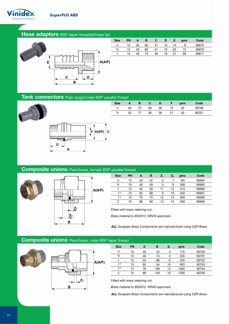
Hose adaptors BSP taper threaded/hose tail Size PN A B C D E gms Code
½ 12 26 60 41 13 14 8 90675 ¾ 12 28 66 41 16 20 15 90676 1 12 40 73 46 19 27 28 90677
Tank connectors Plain spigot/male BSP parallel thread Size A B C D F gms Code
½ 28 70 38 28 15 26 90706
¾ 33 77 38 38 21 30 90707
Size PN A B Z1 Z2 gms Code
½ 15 40 42 3 7 165 90694 ¾ 15 48 49 3 9 290 90695 1 15 55 59 11 12 310 90696 1¼ 15 65 68 9 10 450 90697 1½ 15 79 75 12 14 800 90698 2 15 88 90 14 14 950 90699
Fitted with brass retaining nut.
Brass material to BS2872, WRAS approved.
ALL Durapipe Brass Components are manufactured using DZR Brass.
Size PN A B Z1 gms Code
½ 15 40 54 3 175 90700 ¾ 15 48 74 3 320 90701 1 15 55 86 8 420 90702 1¼ 15 65 94 10 620 90703 1½ 15 78 108 13 1000 90704 2 15 88 129 15 1200 90705
Fitted with brass retaining nut.
Brass material to BS2872, WRAS approved.
ALL Durapipe Brass Components are manufactured using DZR Brass.
SuperFLO ABS
25
B
A
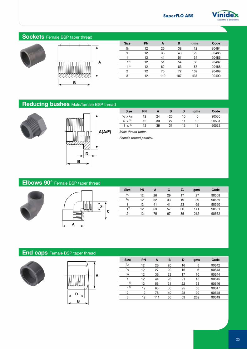
Sockets Female BSP taper thread
A
Z1
C
Elbows 90° Female BSP taper thread
B
D
A(A/F)
Reducing bushes Male/female BSP thread
B
A
D
End caps Female BSP taper thread
Size PN A B gms Code
½ 12 26 38 12 90484 ¾ 12 33 43 22 90485 1 12 41 51 34 90486 1¼ 12 51 54 60 90487 1½ 12 62 63 87 90488 2 12 75 72 132 90489 3 12 110 107 437 90490
Size PN A C Z1 gms Code
½ 12 26 29 17 27 90558 ¾ 12 32 33 19 39 90559 1 12 41 41 23 65 90560 1½ 12 63 57 30 141 90561 2 12 75 67 35 212 90562
Size PN A B D gms Code
½ x 3/8 12 24 25 10 5 90530 ¾ x ½ 12 30 27 11 10 90531 1 x ¾ 12 36 31 12 13 90532
Male thread taper.
Female thread parallel.
Size PN A B D gms Code
3/8 12 26 20 16 5 90642 ½ 12 27 20 16 6 90643 ¾ 12 36 23 17 10 90644 1 12 44 28 21 18 90645 1¼ 12 55 31 22 33 90646 1½ 12 63 35 25 50 90647 2 12 78 40 28 90 90648 3 12 111 65 53 262 90649
SuperFLO ABS
26
B
A(A/F)C
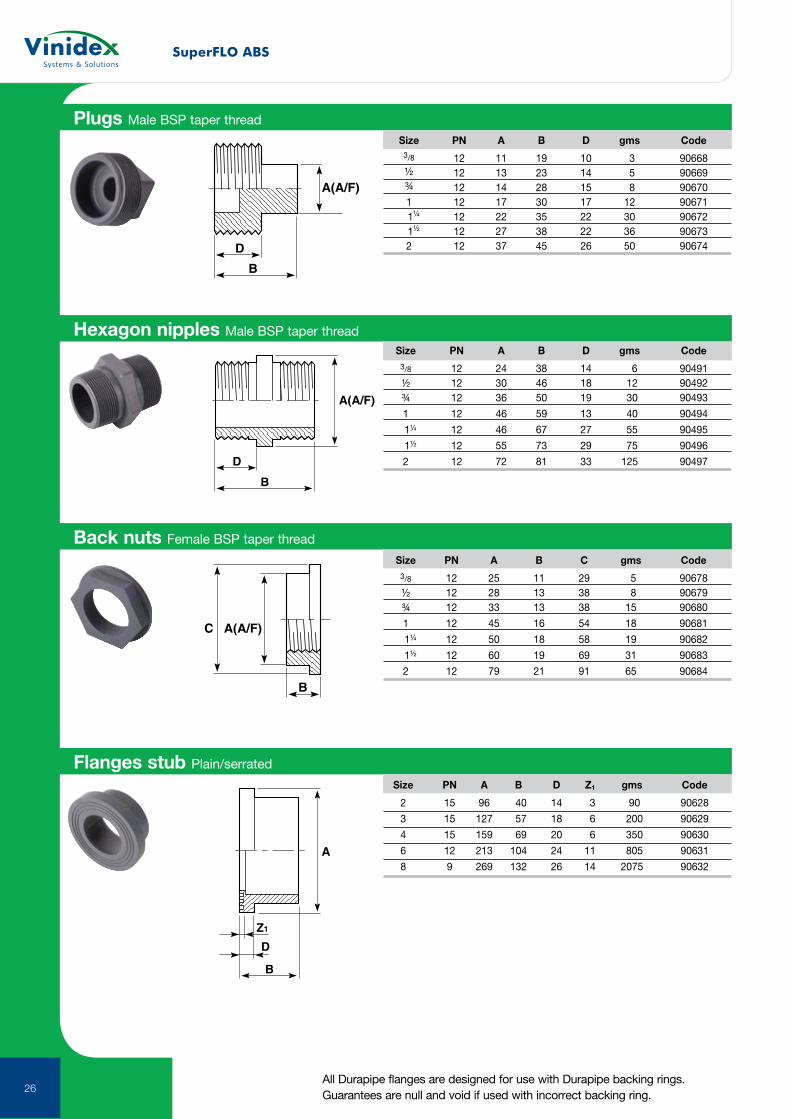
Back nuts Female BSP taper thread
Size PN A B C gms Code
3/8 12 25 11 29 5 90678 ½ 12 28 13 38 8 90679 ¾ 12 33 13 38 15 90680
1 12 45 16 54 18 90681
1¼ 12 50 18 58 19 90682
1½ 12 60 19 69 31 90683
2 12 79 21 91 65 90684
Flanges stub Plain/serrated
Size PN A B D Z1 gms Code
2 15 96 40 14 3 90 90628
3 15 127 57 18 6 200 90629
4 15 159 69 20 6 350 90630
6 12 213 104 24 11 805 90631
8 9 269 132 26 14 2075 90632
B
D
A(A/F)
Plugs Male BSP taper thread
Size PN A B D gms Code
3/8 12 11 19 10 3 90668 ½ 12 13 23 14 5 90669 ¾ 12 14 28 15 8 90670 1 12 17 30 17 12 90671 1¼ 12 22 35 22 30 90672 1½ 12 27 38 22 36 90673 2 12 37 45 26 50 90674
B
D
A(A/F)
Hexagon nipples Male BSP taper thread Size PN A B D gms Code
3/8 12 24 38 14 6 90491 ½ 12 30 46 18 12 90492 ¾ 12 36 50 19 30 90493
1 12 46 59 13 40 90494
1¼ 12 46 67 27 55 90495
1½ 12 55 73 29 75 90496
2 12 72 81 33 125 90497
B
D
Z1
A
All Durapipe flanges are designed for use with Durapipe backing rings. Guarantees are null and void if used with incorrect backing ring.
SuperFLO ABS
27All Durapipe flanges are designed for use with Durapipe backing rings. Guarantees are null and void if used with incorrect backing ring.
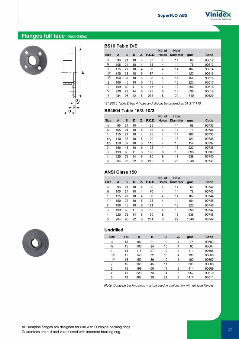
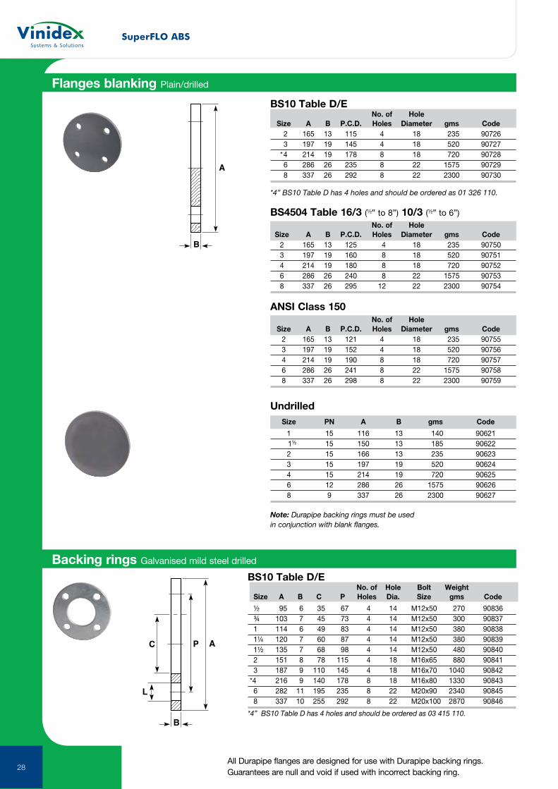
Flanges full face Plain/drilled
Note: Durapipe backing rings must be used in conjunction with full face flanges.
A
Z1
D B
BS10 Table D/E No. of Hole Size A B D Z1 P.C.D. Holes Diameter gms Code
½ 96 21 10 4 67 4 14 68 90612 ¾ 105 24 10 4 73 4 14 78 90613 1 115 27 10 4 83 4 14 107 90614 1¼ 140 33 10 5 87 4 14 122 90615 1½ 150 37 10 5 98 4 14 154 90616 2 166 45 10 6 115 4 18 223 90617 3 199 60 11 8 145 4 18 398 90618 *4 220 72 14 6 178 8 18 638 90619 6 284 98 22 8 235 8 22 1340 90620
*4” BS10 Table D has 4 holes and should be ordered as 01 317 110.
No. of Hole Size A B D Z1 P.C.D. Holes Diameter gms Code
½ 96 21 10 4 65 4 14 68 90733 ¾ 105 24 10 4 75 4 14 78 90734 1 115 27 10 4 85 4 14 107 90735 11⁄4 140 33 10 5 100 4 18 122 90736 11⁄2 150 37 10 5 110 4 18 154 90737 2 166 45 10 6 125 4 18 223 90738 3 199 60 11 8 160 8 18 398 90739 4 220 72 14 6 180 8 18 638 90740 6 284 98 22 8 240 8 22 1340 90741
No. of Hole Size A B D Z1 P.C.D. Holes Diameter gms Code
½ 96 21 10 4 60 4 14 68 90742 ¾ 105 24 10 4 70 4 14 78 90743 1 115 27 10 4 80 4 14 107 90744 1½ 150 37 10 5 98 4 14 154 90745 2 166 45 10 6 121 4 18 223 90746 3 199 60 11 8 152 4 18 398 90747 4 220 72 14 6 190 8 18 638 90748 6 284 98 22 8 241 8 22 1340 90749
Size PN A B D Z1 gms Code
½ 15 96 21 10 4 75 90603 ¾ 15 105 24 10 4 85 90604 1 15 115 27 10 4 111 90605 1¼ 15 140 32 10 4 130 90606 1½ 15 150 36 10 5 160 90607 2 15 165 45 11 6 233 90608 3 15 199 60 11 8 414 90609 4 15 220 73 14 6 657 90610 6 12 284 99 22 8 1417 90611
Undrilled
BS4504 Table 16/3-10/3
ANSI Class 150
SuperFLO ABS
28
ANSI Class 150 No. of Hole Size A B P.C.D. Holes Diameter gms Code 2 165 13 121 4 18 235 90755 3 197 19 152 4 18 520 90756 4 214 19 190 8 18 720 90757 6 286 26 241 8 22 1575 90758 8 337 26 298 8 22 2300 90759
B
A
BS10 Table D/E No. of Hole Size A B P.C.D. Holes Diameter gms Code 2 165 13 115 4 18 235 90726 3 197 19 145 4 18 520 90727 *4 214 19 178 8 18 720 90728 6 286 26 235 8 22 1575 90729 8 337 26 292 8 22 2300 90730
*4” BS10 Table D has 4 holes and should be ordered as 01 326 110.
Flanges blanking Plain/drilled
Backing rings Galvanised mild steel drilled
Size PN A B gms Code
1 15 116 13 140 90621 1½ 15 150 13 185 90622 2 15 166 13 235 90623 3 15 197 19 520 90624 4 15 214 19 720 90625 6 12 286 26 1575 90626 8 9 337 26 2300 90627
Note: Durapipe backing rings must be used in conjunction with blank flanges.
Undrilled
BS4504 Table 16/3 (½” to 8”) 10/3 (½” to 6”) No. of Hole Size A B P.C.D. Holes Diameter gms Code 2 165 13 125 4 18 235 90750 3 197 19 160 8 18 520 90751 4 214 19 180 8 18 720 90752 6 286 26 240 8 22 1575 90753 8 337 26 295 12 22 2300 90754
B
AC P
L
BS10 Table D/E No. of Hole Bolt Weight Size A B C P Holes Dia. Size gms Code ½ 95 6 35 67 4 14 M12x50 270 90836 ¾ 103 7 45 73 4 14 M12x50 300 90837 1 114 6 49 83 4 14 M12x50 380 90838 1¼ 120 7 60 87 4 14 M12x50 380 90839 1½ 135 7 68 98 4 14 M12x50 480 90840 2 151 8 78 115 4 18 M16x65 880 90841 3 187 9 110 145 4 18 M16x70 1040 90842 *4 216 9 140 178 8 18 M16x80 1330 90843 6 282 11 195 235 8 22 M20x90 2340 90845 8 337 10 255 292 8 22 M20x100 2870 90846
*4” BS10 Table D has 4 holes and should be ordered as 03 415 110.
All Durapipe flanges are designed for use with Durapipe backing rings. Guarantees are null and void if used with incorrect backing ring.
SuperFLO ABS
29
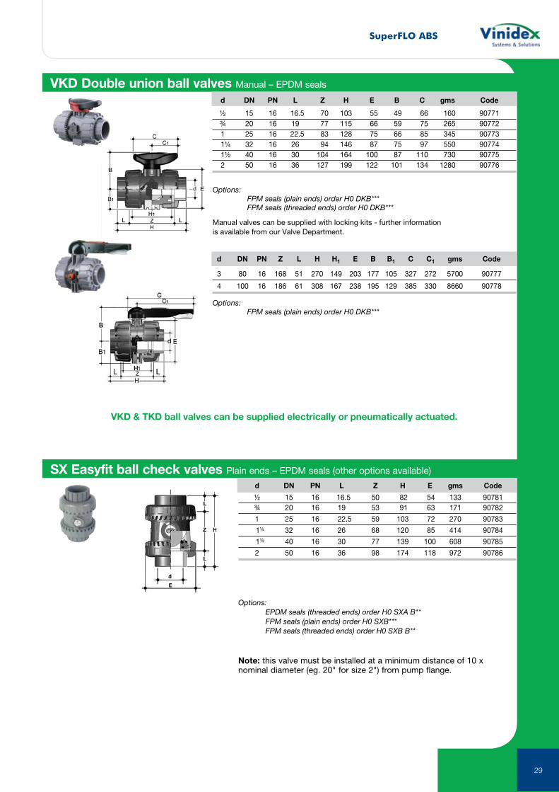
VKD Double union ball valves Manual – EPDM seals
Options: FPM seals (plain ends) order H0 DKB*** FPM seals (threaded ends) order H0 DKB***
Manual valves can be supplied with locking kits - further information is available from our Valve Department.
d DN PN L Z H E B C gms Code
½ 15 16 16.5 70 103 55 49 66 160 90771 ¾ 20 16 19 77 115 66 59 75 265 90772 1 25 16 22.5 83 128 75 66 85 345 90773 1¼ 32 16 26 94 146 87 75 97 550 90774 1½ 40 16 30 104 164 100 87 110 730 90775 2 50 16 36 127 199 122 101 134 1280 90776
d DN PN Z L H H1 E B B1 C C1 gms Code
3 80 16 168 51 270 149 203 177 105 327 272 5700 90777
4 100 16 186 61 308 167 238 195 129 385 330 8660 90778
Options: FPM seals (plain ends) order H0 DKB***
VKD & TKD ball valves can be supplied electrically or pneumatically actuated.
SX Easyfit ball check valves Plain ends – EPDM seals (other options available)
Options: EPDM seals (threaded ends) order H0 SXA B** FPM seals (plain ends) order H0 SXB*** FPM seals (threaded ends) order H0 SXB B**
Note: this valve must be installed at a minimum distance of 10 x nominal diameter (eg. 20" for size 2") from pump flange.
d DN PN L Z H E gms Code
½ 15 16 16.5 50 82 54 133 90781 ¾ 20 16 19 53 91 63 171 90782
1 25 16 22.5 59 103 72 270 90783
1¼ 32 16 26 68 120 85 414 90784
1½ 40 16 30 77 139 100 608 90785
2 50 16 36 98 174 118 972 90786
SuperFLO ABS
30
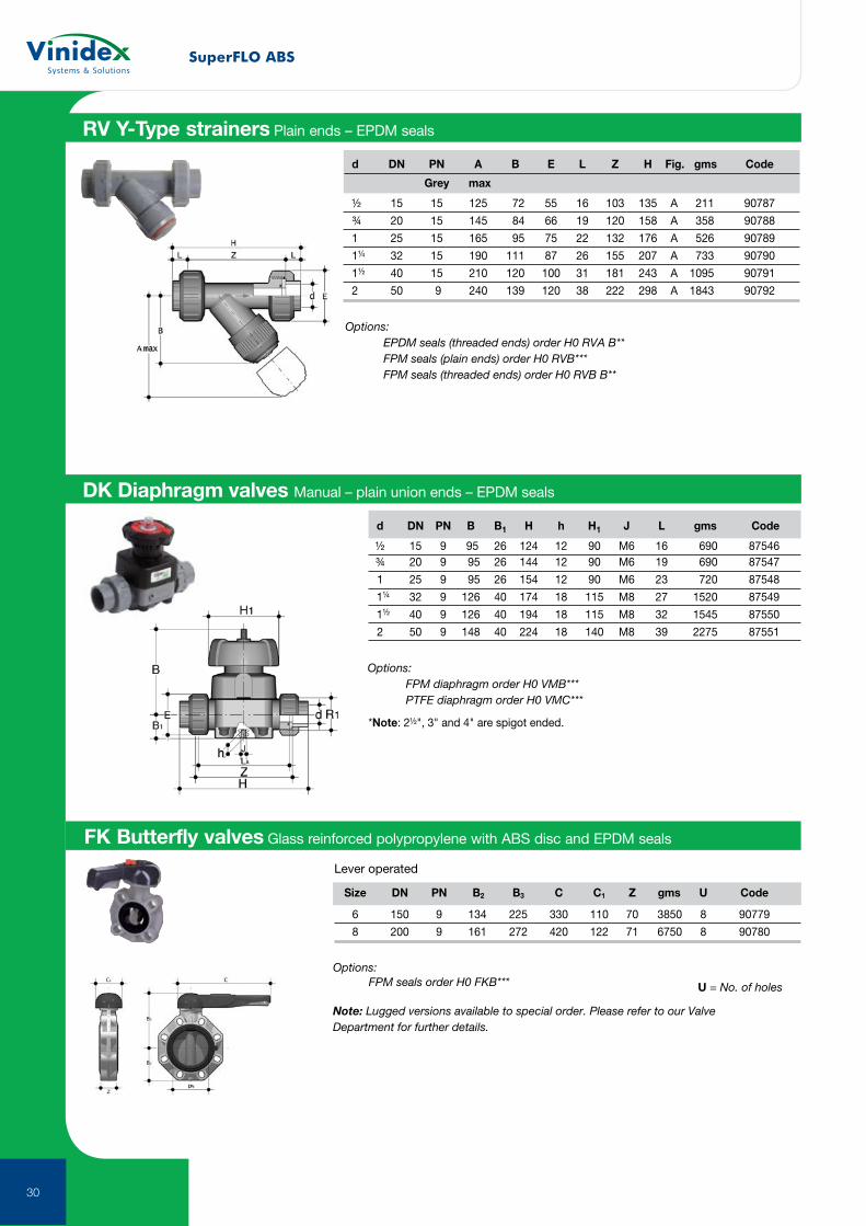
RV Y-Type strainers Plain ends – EPDM seals
Options: EPDM seals (threaded ends) order H0 RVA B** FPM seals (plain ends) order H0 RVB*** FPM seals (threaded ends) order H0 RVB B**
d DN PN A B E L Z H Fig. gms Code
Grey max
½ 15 15 125 72 55 16 103 135 A 211 90787
¾ 20 15 145 84 66 19 120 158 A 358 90788
1 25 15 165 95 75 22 132 176 A 526 90789
1¼ 32 15 190 111 87 26 155 207 A 733 90790
1½ 40 15 210 120 100 31 181 243 A 1095 90791
2 50 9 240 139 120 38 222 298 A 1843 90792
DK Diaphragm valves Manual – plain union ends – EPDM seals
Options: FPM diaphragm order H0 VMB*** PTFE diaphragm order H0 VMC***
d DN PN B B1 H h H1 J L gms Code
½ 15 9 95 26 124 12 90 M6 16 690 87546 ¾ 20 9 95 26 144 12 90 M6 19 690 87547
1 25 9 95 26 154 12 90 M6 23 720 87548
1¼ 32 9 126 40 174 18 115 M8 27 1520 87549
1½ 40 9 126 40 194 18 115 M8 32 1545 87550
2 50 9 148 40 224 18 140 M8 39 2275 87551
*Note: 2½", 3" and 4" are spigot ended.
Size DN PN B2 B3 C C1 Z gms U Code
6 150 9 134 225 330 110 70 3850 8 90779
8 200 9 161 272 420 122 71 6750 8 90780
FK Butterfly valves Glass reinforced polypropylene with ABS disc and EPDM seals
Lever operated
Options: FPM seals order H0 FKB*** U = No. of holes
Note: Lugged versions available to special order. Please refer to our Valve Department for further details.
SuperFLO ABS
31
BG
C
A
D
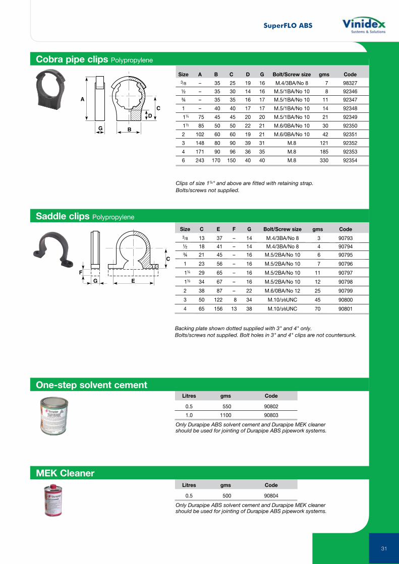
Cobra pipe clips Polypropylene
Size A B C D G Bolt/Screw size gms Code
3/8 – 35 25 19 16 M.4/3BA/No 8 7 98327
½ – 35 30 14 16 M.5/1BA/No 10 8 92346
¾ – 35 35 16 17 M.5/1BA/No 10 11 92347
1 – 40 40 17 17 M.5/1BA/No 10 14 92348
1¼ 75 45 45 20 20 M.5/1BA/No 10 21 92349
1½ 85 50 50 22 21 M.6/0BA/No 10 30 92350
2 102 60 60 19 21 M.6/0BA/No 10 42 92351
3 148 80 90 39 31 M.8 121 92352
4 171 90 96 36 35 M.8 185 92353
6 243 170 150 40 40 M.8 330 92354
Clips of size 1¼" and above are fitted with retaining strap. Bolts/screws not supplied.
G E
C
F
Saddle clips Polypropylene
Size C E F G Bolt/Screw size gms Code
3/8 13 37 – 14 M.4/3BA/No 8 3 90793
½ 18 41 – 14 M.4/3BA/No 8 4 90794
¾ 21 45 – 16 M.5/2BA/No 10 6 90795
1 23 56 – 16 M.5/2BA/No 10 7 90796
1¼ 29 65 – 16 M.5/2BA/No 10 11 90797
1½ 34 67 – 16 M.5/2BA/No 10 12 90798
2 38 87 – 22 M.6/0BA/No 12 25 90799
3 50 122 8 34 M.10/3⁄8UNC 45 90800
4 65 156 13 38 M.10/3⁄8UNC 70 90801
Backing plate shown dotted supplied with 3" and 4" only. Bolts/screws not supplied. Bolt holes in 3" and 4" clips are not countersunk.
One-step solvent cement
Only Durapipe ABS solvent cement and Durapipe MEK cleaner should be used for jointing of Durapipe ABS pipework systems.
MEK Cleaner Litres gms Code
0.5 500 90804
Only Durapipe ABS solvent cement and Durapipe MEK cleaner should be used for jointing of Durapipe ABS pipework systems.
Litres gms Code
0.5 550 90802
1.0 1100 90803
SuperFLO ABS
32
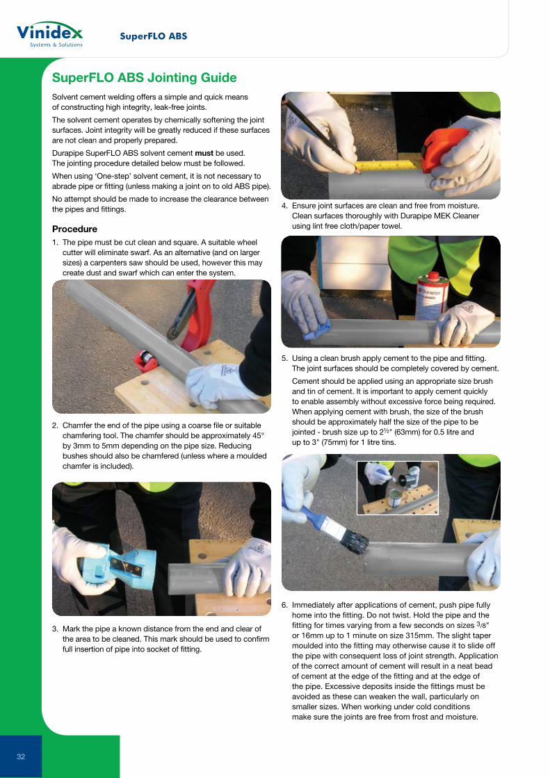
SuperFLO ABS Jointing GuideSolvent cement welding offers a simple and quick means of constructing high integrity, leak-free joints.
The solvent cement operates by chemically softening the joint surfaces. Joint integrity will be greatly reduced if these surfaces are not clean and properly prepared.
Durapipe SuperFLO ABS solvent cement must be used. The jointing procedure detailed below must be followed.
When using ‘One-step’ solvent cement, it is not necessary to abrade pipe or fitting (unless making a joint on to old ABS pipe).
No attempt should be made to increase the clearance between the pipes and fittings.
Procedure1. The pipe must be cut clean and square. A suitable wheel
cutter will eliminate swarf. As an alternative (and on larger sizes) a carpenters saw should be used, however this may create dust and swarf which can enter the system.
2. Chamfer the end of the pipe using a coarse file or suitable chamfering tool. The chamfer should be approximately 45° by 3mm to 5mm depending on the pipe size. Reducing bushes should also be chamfered (unless where a moulded chamfer is included).
3. Mark the pipe a known distance from the end and clear of the area to be cleaned. This mark should be used to confirm full insertion of pipe into socket of fitting.
4. Ensure joint surfaces are clean and free from moisture. Clean surfaces thoroughly with Durapipe MEK Cleaner
using lint free cloth/paper towel.
5. Using a clean brush apply cement to the pipe and fitting. The joint surfaces should be completely covered by cement.
Cement should be applied using an appropriate size brush and tin of cement. It is important to apply cement quickly to enable assembly without excessive force being required.
When applying cement with brush, the size of the brush should be approximately half the size of the pipe to be jointed - brush size up to 2½" (63mm) for 0.5 litre and up to 3" (75mm) for 1 litre tins.
6. Immediately after applications of cement, push pipe fully home into the fitting. Do not twist. Hold the pipe and the fitting for times varying from a few seconds on sizes 3/8" or 16mm up to 1 minute on size 315mm. The slight taper moulded into the fitting may otherwise cause it to slide off the pipe with consequent loss of joint strength. Application of the correct amount of cement will result in a neat bead of cement at the edge of the fitting and at the edge of the pipe. Excessive deposits inside the fittings must be avoided as these can weaken the wall, particularly on smaller sizes. When working under cold conditions make sure the joints are free from frost and moisture.
SuperFLO ABS
33
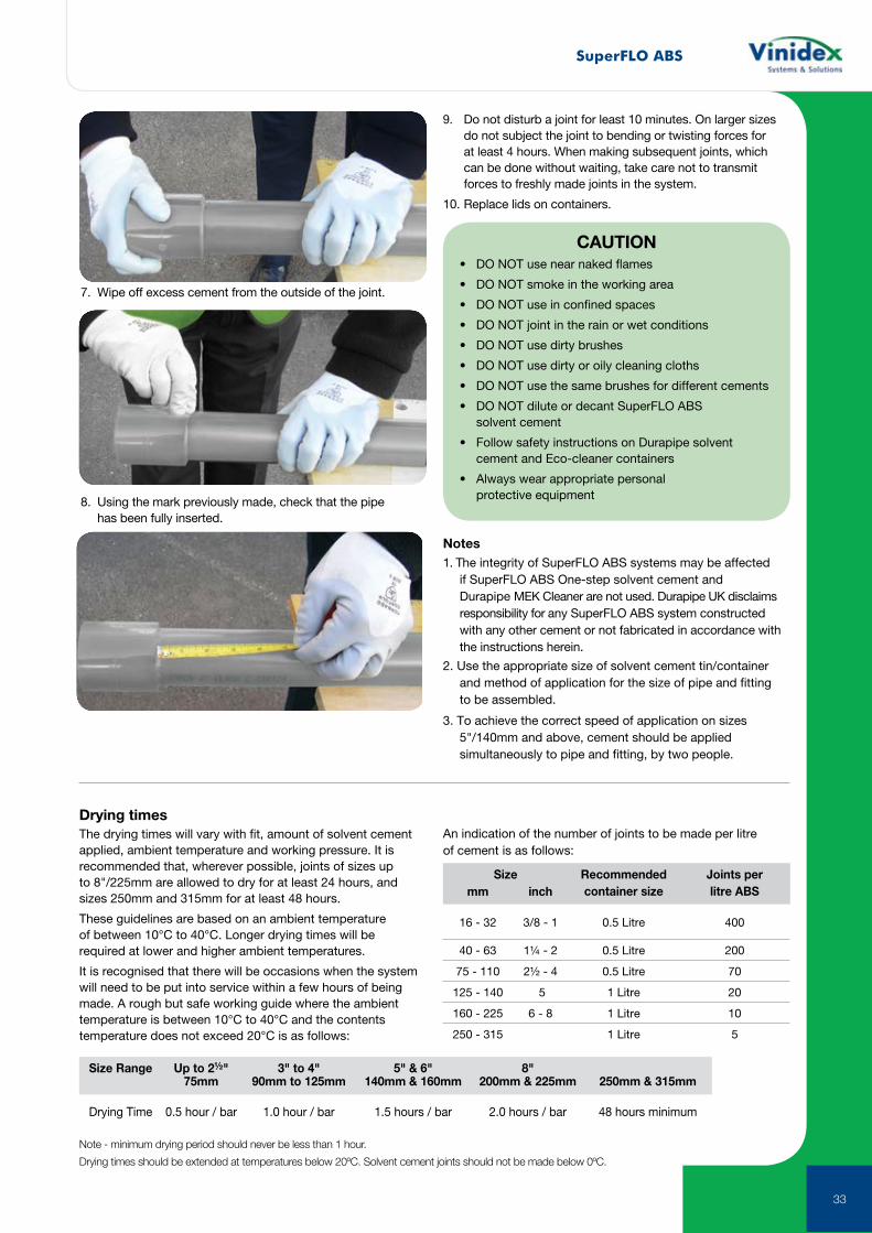
7. Wipe off excess cement from the outside of the joint.
8. Using the mark previously made, check that the pipe has been fully inserted.
Notes1. The integrity of SuperFLO ABS systems may be affected
if SuperFLO ABS One-step solvent cement and Durapipe MEK Cleaner are not used. Durapipe UK disclaims responsibility for any SuperFLO ABS system constructed with any other cement or not fabricated in accordance with the instructions herein.
2. Use the appropriate size of solvent cement tin/container and method of application for the size of pipe and fitting to be assembled.
3. To achieve the correct speed of application on sizes 5"/140mm and above, cement should be applied simultaneously to pipe and fitting, by two people.
Note - minimum drying period should never be less than 1 hour.
Drying times should be extended at temperatures below 20ºC. Solvent cement joints should not be made below 0ºC.
Size Range Up to 2½" 3" to 4" 5" & 6" 8" 75mm 90mm to 125mm 140mm & 160mm 200mm & 225mm 250mm & 315mm
Drying Time 0.5 hour / bar 1.0 hour / bar 1.5 hours / bar 2.0 hours / bar 48 hours minimum
Drying timesThe drying times will vary with fit, amount of solvent cement applied, ambient temperature and working pressure. It is recommended that, wherever possible, joints of sizes up to 8"/225mm are allowed to dry for at least 24 hours, and sizes 250mm and 315mm for at least 48 hours.
These guidelines are based on an ambient temperature of between 10°C to 40°C. Longer drying times will be required at lower and higher ambient temperatures.
It is recognised that there will be occasions when the system will need to be put into service within a few hours of being made. A rough but safe working guide where the ambient temperature is between 10°C to 40°C and the contents temperature does not exceed 20°C is as follows:
An indication of the number of joints to be made per litre of cement is as follows:
9. Do not disturb a joint for least 10 minutes. On larger sizes do not subject the joint to bending or twisting forces for at least 4 hours. When making subsequent joints, which can be done without waiting, take care not to transmit forces to freshly made joints in the system.
10. Replace lids on containers.
CAUTION• DO NOT use near naked flames
• DO NOT smoke in the working area
• DO NOT use in confined spaces
• DO NOT joint in the rain or wet conditions
• DO NOT use dirty brushes
• DO NOT use dirty or oily cleaning cloths
• DO NOT use the same brushes for different cements
• DO NOT dilute or decant SuperFLO ABS solvent cement
• Follow safety instructions on Durapipe solvent cement and Eco-cleaner containers
• Always wear appropriate personal protective equipment
Size Recommended container size
Joints per litre ABSmm inch
16 - 32 3/8 - 1 0.5 Litre 400
40 - 63 1¼ - 2 0.5 Litre 200
75 - 110 2½ - 4 0.5 Litre 70
125 - 140 5 1 Litre 20
160 - 225 6 - 8 1 Litre 10
250 - 315 1 Litre 5
SuperFLO ABS
34
Chemical resistanceand performance data
Typical applications
Unsuitable for the following uses
Sizes and jointinginformation
Moderately strong mineral acids Chilled water Applications over 60ºC Metric: 16mm to 315mm OD
Caustic and ammoniacal solutions Low temperature brine Bleaches Imperial: 3/8" to 8" NB
Most inorganic salt solutions Potable water Solvents Jointed by solvent cement welding
Some detergents Process water Domestic hot water Threaded fittings available
Temperature range -40ºC to +60ºC Flammable substances
Note: Temperatures given are for guidance only, please check before specifying.
Properties guide
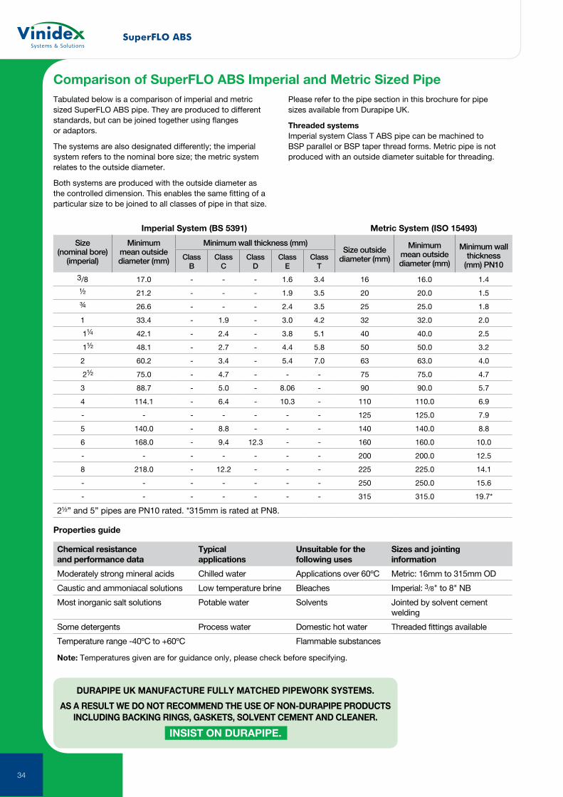
Tabulated below is a comparison of imperial and metric sized SuperFLO ABS pipe. They are produced to different standards, but can be joined together using flanges or adaptors.
The systems are also designated differently; the imperial system refers to the nominal bore size; the metric system relates to the outside diameter.
Both systems are produced with the outside diameter as the controlled dimension. This enables the same fitting of a particular size to be joined to all classes of pipe in that size.
Please refer to the pipe section in this brochure for pipe sizes available from Durapipe UK.
Threaded systems Imperial system Class T ABS pipe can be machined to BSP parallel or BSP taper thread forms. Metric pipe is not produced with an outside diameter suitable for threading.
Comparison of SuperFLO ABS Imperial and Metric Sized Pipe
Imperial System (BS 5391) Metric System (ISO 15493)
Size (nominal bore)
(imperial)
Minimum mean outside diameter (mm)
Minimum wall thickness (mm)Size outside
diameter (mm)
Minimum mean outside diameter (mm)
Minimum wall thickness
(mm) PN10Class
BClass
CClass
DClass
EClass
T
3/8 17.0 - - - 1.6 3.4 16 16.0 1.4
½ 21.2 - - - 1.9 3.5 20 20.0 1.5
¾ 26.6 - - - 2.4 3.5 25 25.0 1.8
1 33.4 - 1.9 - 3.0 4.2 32 32.0 2.0
1¼ 42.1 - 2.4 - 3.8 5.1 40 40.0 2.5
1½ 48.1 - 2.7 - 4.4 5.8 50 50.0 3.2
2 60.2 - 3.4 - 5.4 7.0 63 63.0 4.0
2½ 75.0 - 4.7 - - - 75 75.0 4.7
3 88.7 - 5.0 - 8.06 - 90 90.0 5.7
4 114.1 - 6.4 - 10.3 - 110 110.0 6.9
- - - - - - - 125 125.0 7.9
5 140.0 - 8.8 - - - 140 140.0 8.8
6 168.0 - 9.4 12.3 - - 160 160.0 10.0
- - - - - - - 200 200.0 12.5
8 218.0 - 12.2 - - - 225 225.0 14.1
- - - - - - - 250 250.0 15.6
- - - - - - - 315 315.0 19.7*
2½” and 5” pipes are PN10 rated. *315mm is rated at PN8.
DURAPIPE UK MANUFACTURE FULLY MATCHED PIPEWORK SYSTEMS.
AS A RESULT WE DO NOT RECOMMEND THE USE OF NON-DURAPIPE PRODUCTS INCLUDING BACKING RINGS, GASKETS, SOLVENT CEMENT AND CLEANER.
INSIST ON DURAPIPE.

SuperFLO ABS
35
Double Containment SystemsSafety and environmental concerns are top priorities on today’s industrial agenda. Reduction of emissions, energy conservation and prevention of ground water contamination are some of the areas where regulations are increasingly defining an important line between utilisation and exploitation of our planet’s resources.
For most common chemical-waste or process applications, Vinidex offers systems that are both simple yet highly advanced state-of-the-art technologies. These systems utilize pre-assembled components that guarantee reliability, ease of installation, fewer joints (up to 40% less) and quick delivery.
Certain environments demand fail-safe systems. No leaks. No risk. We understand the complexity of design and installation for demanding double containment applications.
36
For more than 30 years, Guardian systems have been the benchmark in pressure and drainage double containment. Guardian systems are available in tough industrial grade PVC and even tougher high temperature CPVC. For instant leak detection of overhead piping, Clear-Guard clear PVC containment pipe is also available. Guardian’s patented Centra-Lock design reduces the required joints by 40 - 60% compared to conventional double containment Systems.
Clear-Guard’s fail-safe, fully pressure rated clear containment system allows for easy detection of leaks and eliminates the risks associated with piping aggressive chemicals overhead. Clear-Guard utilizes Guardian’s patented Centra-Lok fitting design, which reduces the required joints by 40-60% compared to conventional double containment systems. Fittings are available in clear or opaque containment fittings.
Custom-designed and fabricated double containment systems including dissimilar material systems, CustomGuard is unlike other systems that try to run everything through the same material.
For applications with more demanding mechanical, chemical and/or thermal requirements, we have developed our CustomGuard offering. CustomGuard includes a variety of different system choices ranging from Fluoropolymers (e.g. PVDF), Thermosets (FRP); and carbon and stainless steel to hybrid combinations.
Applications that require such materials are obviously complex, each demanding expertise and specialized knowledge to design an effective system. The CustomGuard option includes material selection, design, specification support (if needed) and fabrication of preassembled spooled pieces to minimize installation time and field joints.
In many situations double containment protection by itself may not be enough. In these applications it is critical that a leak is immediately detected and located.
Although many different leak detection systems are available on the market today, only the Centra-Guard patented electronic low point leak-detection system offers a combination of advanced features including versatility; customization; and lower material, installation and maintenance costs when compared to cable leak detection.
Centra-Guard is suitable for above-ground suspended pipeline applications, with sensors housed in a saddle-type clamp as well as underground pipeline systems with drip leg assembly.
Our PAL-AT cable leak detection is a microprocessor based system that offers continuous cable leak detection. The system is fully automated and ideal for buried double containment piping applications that require exact leak location.
Our PAL-AT continuous cable leak detection system compliments our Centra-Guard electronic low point leak detection system and adds extra versatility to our extensive double containment offering.
Product available on request.
Contact your Vinidex representative for further information.
37
Double Containment Systems
38
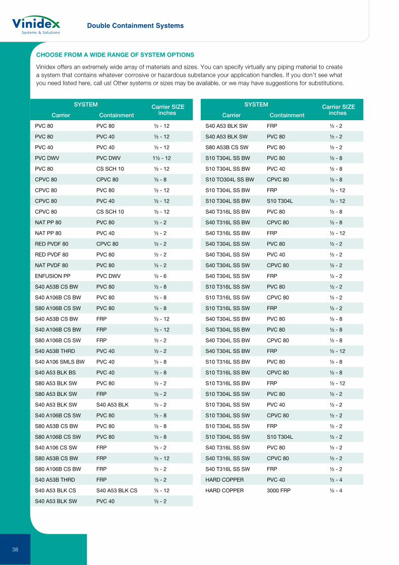
CHOOSE FROM A WIDE RANGE OF SYSTEM OPTIONS
Vinidex offers an extremely wide array of materials and sizes. You can specify virtually any piping material to create a system that contains whatever corrosive or hazardous substance your application handles. If you don’t see what you need listed here, call us! Other systems or sizes may be available, or we may have suggestions for substitutions.
SYSTEM Carrier SIZEinchesCarrier Containment
PVC 80 PVC 80 ½ - 12
PVC 80 PVC 40 ½ - 12
PVC 40 PVC 40 ½ - 12
PVC DWV PVC DWV 1½ - 12
PVC 80 CS SCH 10 ½ - 12
CPVC 80 CPVC 80 ½ - 8
CPVC 80 PVC 80 ½ - 12
CPVC 80 PVC 40 ½ - 12
CPVC 80 CS SCH 10 ½ - 12
NAT PP 80 PVC 80 ½ - 2
NAT PP 80 PVC 40 ½ - 2
RED PVDF 80 CPVC 80 ½ - 2
RED PVDF 80 PVC 80 ½ - 2
NAT PVDF 80 PVC 80 ½ - 2
ENFUSION PP PVC DWV ½ - 6
S40 A53B CS BW PVC 80 ½ - 8
S40 A106B CS BW PVC 80 ½ - 8
S80 A106B CS SW PVC 80 ½ - 8
S40 A53B CS BW FRP ½ - 12
S40 A106B CS BW FRP ½ - 12
S80 A106B CS SW FRP ½ - 2
S40 A53B THRD PVC 40 ½ - 2
S40 A106 SMLS BW PVC 40 ½ - 8
S40 A53 BLK BS PVC 40 ½ - 8
S80 A53 BLK SW PVC 80 ½ - 2
S80 A53 BLK SW FRP ½ - 2
S40 A53 BLK SW S40 A53 BLK ½ - 2
S40 A106B CS SW PVC 80 ½ - 8
S80 A53B CS BW PVC 80 ½ - 8
S80 A106B CS SW PVC 80 ½ - 8
S40 A106 CS SW FRP ½ - 2
S80 A53B CS BW FRP ½ - 12
S80 A106B CS BW FRP ½ - 2
S40 A53B THRD FRP ½ - 2
S40 A53 BLK CS S40 A53 BLK CS ½ - 12
S40 A53 BLK SW PVC 40 ½ - 2
SYSTEM Carrier SIZEinchesCarrier Containment
S40 A53 BLK SW FRP ½ - 2
S40 A53 BLK SW PVC 80 ½ - 2
S80 A53B CS SW PVC 80 ½ - 2
S10 T304L SS BW PVC 80 ½ - 8
S10 T304L SS BW PVC 40 ½ - 8
S10 TO304L SS BW CPVC 80 ½ - 8
S10 T304L SS BW FRP ½ - 12
S10 T304L SS BW S10 T304L ½ - 12
S40 T316L SS BW PVC 80 ½ - 8
S40 T316L SS BW CPVC 80 ½ - 8
S40 T316L SS BW FRP ½ - 12
S40 T304L SS SW PVC 80 ½ - 2
S40 T304L SS SW PVC 40 ½ - 2
S40 T304L SS SW CPVC 80 ½ - 2
S40 T304L SS SW FRP ½ - 2
S10 T316L SS SW PVC 80 ½ - 2
S10 T316L SS SW CPVC 80 ½ - 2
S10 T316L SS SW FRP ½ - 2
S40 T304L SS BW PVC 80 ½ - 8
S40 T304L SS BW PVC 80 ½ - 8
S40 T304L SS BW CPVC 80 ½ - 8
S40 T304L SS BW FRP ½ - 12
S10 T316L SS BW PVC 80 ½ - 8
S10 T316L SS BW CPVC 80 ½ - 8
S10 T316L SS BW FRP ½ - 12
S10 T304L SS SW PVC 80 ½ - 2
S10 T304L SS SW PVC 40 ½ - 2
S10 T304L SS SW CPVC 80 ½ - 2
S10 T304L SS SW FRP ½ - 2
S10 T304L SS SW S10 T304L ½ - 2
S40 T316L SS SW PVC 80 ½ - 2
S40 T316L SS SW CPVC 80 ½ - 2
S40 T316L SS SW FRP ½ - 2
HARD COPPER PVC 40 ½ - 4
HARD COPPER 3000 FRP ½ - 4

39
Acid Waste Piping Systems
40

Safe chemical drainage
Vulcathene boasts over 60 years proven performance in the laboratories of thousands of schools, universities, hospitals and research facilities around the world ... proof of its very high reliability for safe chemical drainage.
Vulcathene is specified worldwide and proven as the world leading solution for chemical waste drainage. It has two easy jointing methods – Mechanical or Enfusion. Fittings are injection moulded and purpose designed.
41
Vulcathene PP
42
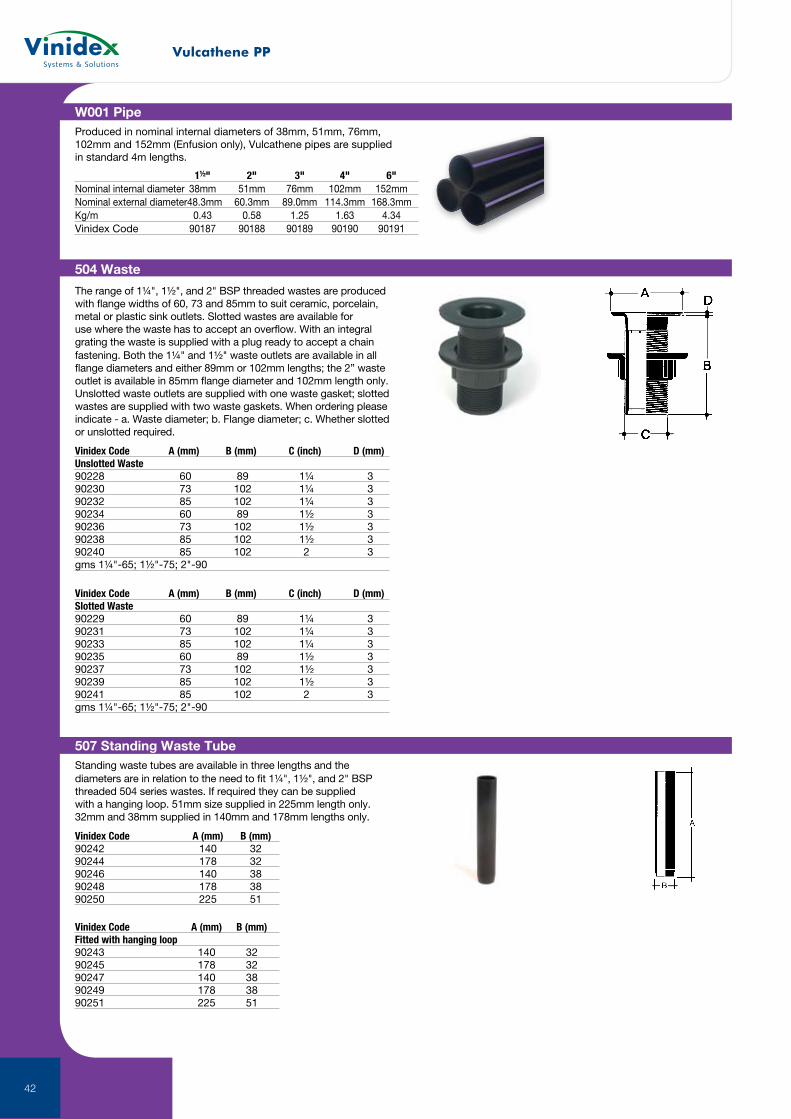
W001 PipeProduced in nominal internal diameters of 38mm, 51mm, 76mm, 102mm and 152mm (Enfusion only), Vulcathene pipes are supplied in standard 4m lengths.
1½" 2" 3" 4" 6"Nominal internal diameter 38mm 51mm 76mm 102mm 152mmNominal external diameter 48.3mm 60.3mm 89.0mm 114.3mm 168.3mmKg/m 0.43 0.58 1.25 1.63 4.34Vinidex Code 90187 90188 90189 90190 90191
507 Standing Waste TubeStanding waste tubes are available in three lengths and the diameters are in relation to the need to fit 1¼", 1½", and 2" BSP threaded 504 series wastes. If required they can be supplied with a hanging loop. 51mm size supplied in 225mm length only. 32mm and 38mm supplied in 140mm and 178mm lengths only.
Vinidex Code A (mm) B (mm)90242 140 3290244 178 3290246 140 3890248 178 3890250 225 51
Vinidex Code A (mm) B (mm)Fitted with hanging loop90243 140 3290245 178 3290247 140 3890249 178 3890251 225 51
The range of 1¼", 1½", and 2" BSP threaded wastes are produced with flange widths of 60, 73 and 85mm to suit ceramic, porcelain, metal or plastic sink outlets. Slotted wastes are available for use where the waste has to accept an overflow. With an integral grating the waste is supplied with a plug ready to accept a chain fastening. Both the 1¼" and 1½" waste outlets are available in all flange diameters and either 89mm or 102mm lengths; the 2” waste outlet is available in 85mm flange diameter and 102mm length only. Unslotted waste outlets are supplied with one waste gasket; slotted wastes are supplied with two waste gaskets. When ordering please indicate - a. Waste diameter; b. Flange diameter; c. Whether slotted or unslotted required.
504 Waste
Vinidex Code A (mm) B (mm) C (inch) D (mm)Unslotted Waste90228 60 89 1¼ 390230 73 102 1¼ 390232 85 102 1¼ 390234 60 89 1½ 390236 73 102 1½ 390238 85 102 1½ 390240 85 102 2 3gms 1¼"-65; 1½"-75; 2"-90
Vinidex Code A (mm) B (mm) C (inch) D (mm)Slotted Waste90229 60 89 1¼ 390231 73 102 1¼ 390233 85 102 1¼ 390235 60 89 1½ 390237 73 102 1½ 390239 85 102 1½ 390241 85 102 2 3gms 1¼"-65; 1½"-75; 2"-90
Vulcathene PP
43
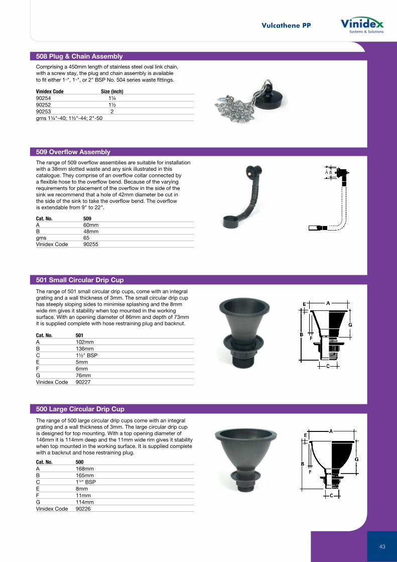
501 Small Circular Drip Cup
The range of 501 small circular drip cups, come with an integral grating and a wall thickness of 3mm. The small circular drip cup has steeply sloping sides to minimise splashing and the 8mm wide rim gives it stability when top mounted in the working surface. With an opening diameter of 86mm and depth of 73mm it is supplied complete with hose restraining plug and backnut.
Cat. No. 501A 102mmB 136mmC 1½" BSPE 5mmF 6mmG 76mmVinidex Code 90227
500 Large Circular Drip Cup
The range of 500 large circular drip cups come with an integral grating and a wall thickness of 3mm. The large circular drip cup is designed for top mounting. With a top opening diameter of 146mm it is 114mm deep and the 11mm wide rim gives it stability when top mounted in the working surface. It is supplied complete with a backnut and hose restraining plug.
Cat. No. 500A 168mmB 165mmC 1½" BSPE 8mmF 11mmG 114mmVinidex Code 90226
509 Overflow Assembly
The range of 509 overflow assemblies are suitable for installation with a 38mm slotted waste and any sink illustrated in this catalogue. They comprise of an overflow collar connected by a flexible hose to the overflow bend. Because of the varying requirements for placement of the overflow in the side of the sink we recommend that a hole of 42mm diameter be cut in the side of the sink to take the overflow bend. The overflow is extendable from 9" to 22".
Cat. No. 509A 60mmB 48mmgms 65Vinidex Code 90255
508 Plug & Chain Assembly
Comprising a 450mm length of stainless steel oval link chain, with a screw stay, the plug and chain assembly is available to fit either 1¼", 1½", or 2" BSP No. 504 series waste fittings.
Vinidex Code Size (inch)90254 1¼90252 1½90253 2gms 1¼"-40; 1½"-44; 2"-50
Vulcathene PP
44
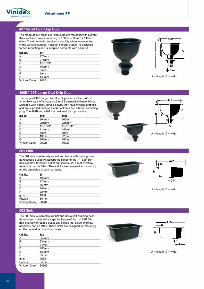
602 Sink
The 602 sink is extremely robust and has a self-draining base. Its recessed outlet will accept the flange of the 1½" BSP 504 non-overflow threaded outlet but, if required, a 509 overflow assembly can be fitted. These sinks are designed for mounting on the underside of work surfaces.
Cat. No. 602A 552mmB 231mmC 74mmD 400mmE 152mmH 35mmgms 2668Radius 35mmVinidex Code 90205
A = length D = width
601 SinkThe 601 sink is extremely robust and has a self-draining base. Its recessed outlet will accept the flange of the 1½" BSP 504 non-overflow threaded outlet but, if required, a 509 overflow assembly can be fitted. These sinks are designed for mounting on the underside of work surfaces.
Cat. No. 601A 492mmB 171mmC 76 mmD 241mmH 32mmgms 1030Radius 36mmVinidex Code 90204
A = length D = width
499B/499T Large Oval Drip Cup
The range of 499 Large Oval Drip Cups are moulded with a 3mm thick wall, offering a choice of 2 alternative flange fixings. Moulded with deeply curved bowls, they have integral gratings and are supplied complete with backnuts and a hose restraining plug. The 499B and 499T are designed for top mounting.
Cat. No. 499B 499TA 264mm 305mmB 225mm 225mmC 1½" BSP 1½" BSPD 111mm 152mmE 6mm 6mmF 13mm 32mmG 161mm 161mmVinidex Code 90225 90223
A = length D = width
497 Small Oval Drip Cup
The range of 497 small oval drip cups are moulded with a 3mm thick wall and have an opening of 166mm x 90mm x 143mm deep. The 6mm wide rim gives it stability when top mounted in the working surface. It has an integral grating, is designed for top mounting and is supplied complete with backnut.
Cat. No. 497A 178mmB 216mmC 1½" BSPD 102mmE 6mmF 6mmG 143mmVinidex Code 90224
A = length D = width
Vulcathene PP
45
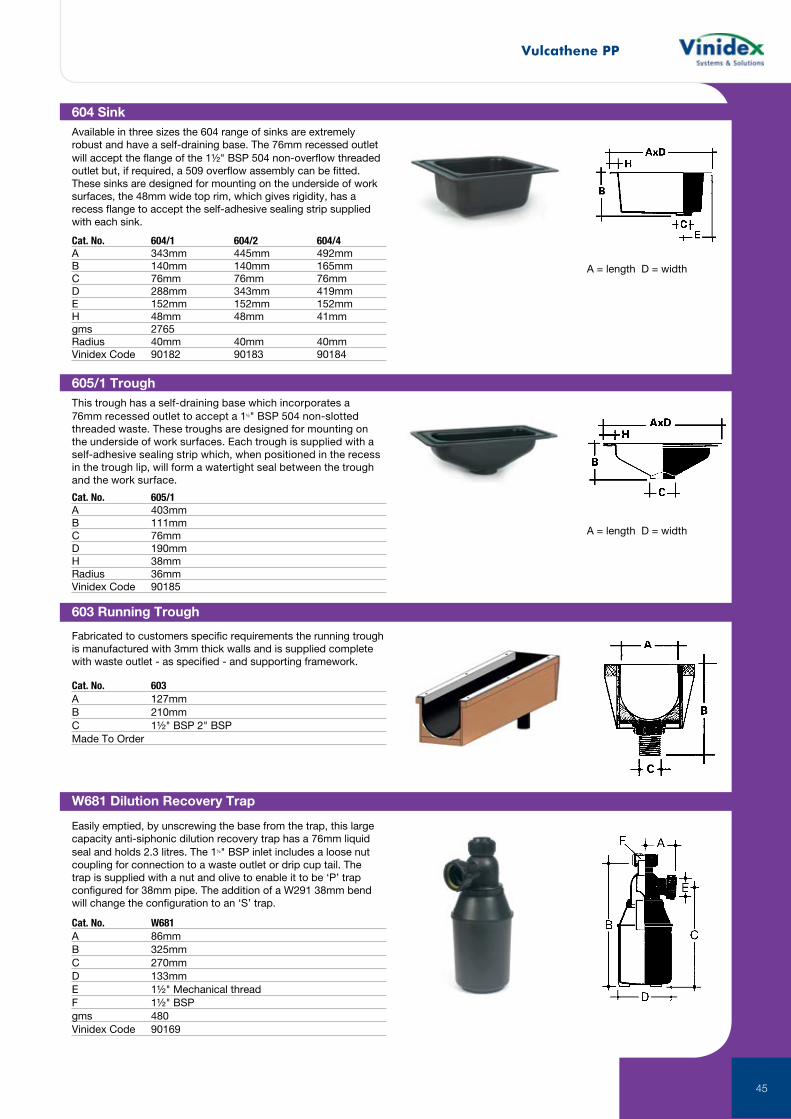
W681 Dilution Recovery Trap
Easily emptied, by unscrewing the base from the trap, this large capacity anti-siphonic dilution recovery trap has a 76mm liquid seal and holds 2.3 litres. The 1½" BSP inlet includes a loose nut coupling for connection to a waste outlet or drip cup tail. The trap is supplied with a nut and olive to enable it to be ‘P’ trap configured for 38mm pipe. The addition of a W291 38mm bend will change the configuration to an ‘S’ trap.
Cat. No. W681A 86mmB 325mmC 270mmD 133mmE 1½" Mechanical threadF 1½" BSPgms 480Vinidex Code 90169
604 SinkAvailable in three sizes the 604 range of sinks are extremely robust and have a self-draining base. The 76mm recessed outlet will accept the flange of the 1½" BSP 504 non-overflow threaded outlet but, if required, a 509 overflow assembly can be fitted. These sinks are designed for mounting on the underside of work surfaces, the 48mm wide top rim, which gives rigidity, has a recess flange to accept the self-adhesive sealing strip supplied with each sink.
Cat. No. 604/1 604/2 604/4A 343mm 445mm 492mmB 140mm 140mm 165mmC 76mm 76mm 76mmD 288mm 343mm 419mmE 152mm 152mm 152mmH 48mm 48mm 41mmgms 2765Radius 40mm 40mm 40mmVinidex Code 90182 90183 90184
A = length D = width
605/1 TroughThis trough has a self-draining base which incorporates a 76mm recessed outlet to accept a 1½" BSP 504 non-slotted threaded waste. These troughs are designed for mounting on the underside of work surfaces. Each trough is supplied with a self-adhesive sealing strip which, when positioned in the recess in the trough lip, will form a watertight seal between the trough and the work surface.
Cat. No. 605/1A 403mmB 111mmC 76mmD 190mmH 38mmRadius 36mmVinidex Code 90185
A = length D = width
603 Running Trough
Fabricated to customers specific requirements the running trough is manufactured with 3mm thick walls and is supplied complete with waste outlet - as specified - and supporting framework.
Cat. No. 603A 127mmB 210mmC 1½" BSP 2" BSPMade To Order
Vulcathene PP
46
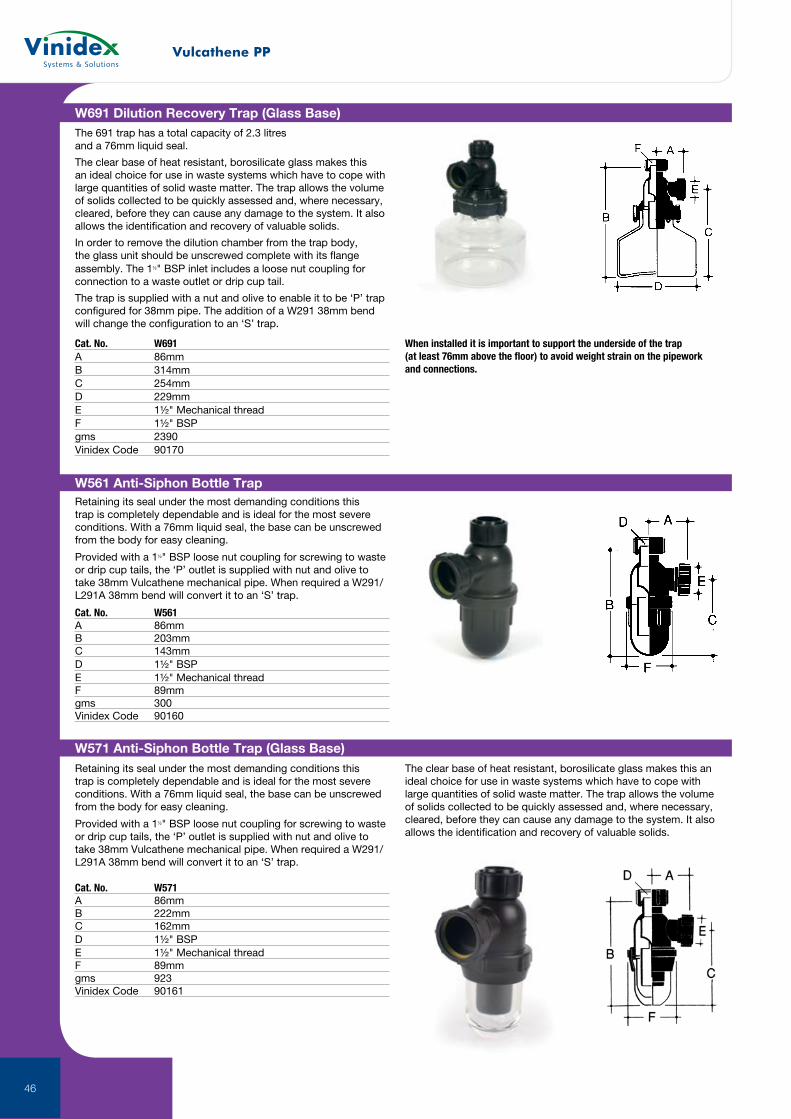
W561 Anti-Siphon Bottle TrapRetaining its seal under the most demanding conditions this trap is completely dependable and is ideal for the most severe conditions. With a 76mm liquid seal, the base can be unscrewed from the body for easy cleaning.
Provided with a 1½" BSP loose nut coupling for screwing to waste or drip cup tails, the ‘P’ outlet is supplied with nut and olive to take 38mm Vulcathene mechanical pipe. When required a W291/L291A 38mm bend will convert it to an ‘S’ trap.
Cat. No. W561A 86mmB 203mmC 143mmD 1½" BSPE 1½" Mechanical threadF 89mmgms 300Vinidex Code 90160
W571 Anti-Siphon Bottle Trap (Glass Base)Retaining its seal under the most demanding conditions this trap is completely dependable and is ideal for the most severe conditions. With a 76mm liquid seal, the base can be unscrewed from the body for easy cleaning.
Provided with a 1½" BSP loose nut coupling for screwing to waste or drip cup tails, the ‘P’ outlet is supplied with nut and olive to take 38mm Vulcathene mechanical pipe. When required a W291/L291A 38mm bend will convert it to an ‘S’ trap.
The clear base of heat resistant, borosilicate glass makes this an ideal choice for use in waste systems which have to cope with large quantities of solid waste matter. The trap allows the volume of solids collected to be quickly assessed and, where necessary, cleared, before they can cause any damage to the system. It also allows the identification and recovery of valuable solids.
Cat. No. W571A 86mmB 222mmC 162mmD 1½" BSPE 1½" Mechanical threadF 89mmgms 923Vinidex Code 90161
W691 Dilution Recovery Trap (Glass Base)The 691 trap has a total capacity of 2.3 litres and a 76mm liquid seal.
The clear base of heat resistant, borosilicate glass makes this an ideal choice for use in waste systems which have to cope with large quantities of solid waste matter. The trap allows the volume of solids collected to be quickly assessed and, where necessary, cleared, before they can cause any damage to the system. It also allows the identification and recovery of valuable solids.
In order to remove the dilution chamber from the trap body, the glass unit should be unscrewed complete with its flange assembly. The 1½" BSP inlet includes a loose nut coupling for connection to a waste outlet or drip cup tail.
The trap is supplied with a nut and olive to enable it to be ‘P’ trap configured for 38mm pipe. The addition of a W291 38mm bend will change the configuration to an ‘S’ trap.
Cat. No. W691A 86mmB 314mmC 254mmD 229mmE 1½" Mechanical threadF 1½" BSPgms 2390Vinidex Code 90170
When installed it is important to support the underside of the trap (at least 76mm above the floor) to avoid weight strain on the pipework and connections.
Vulcathene PP
47
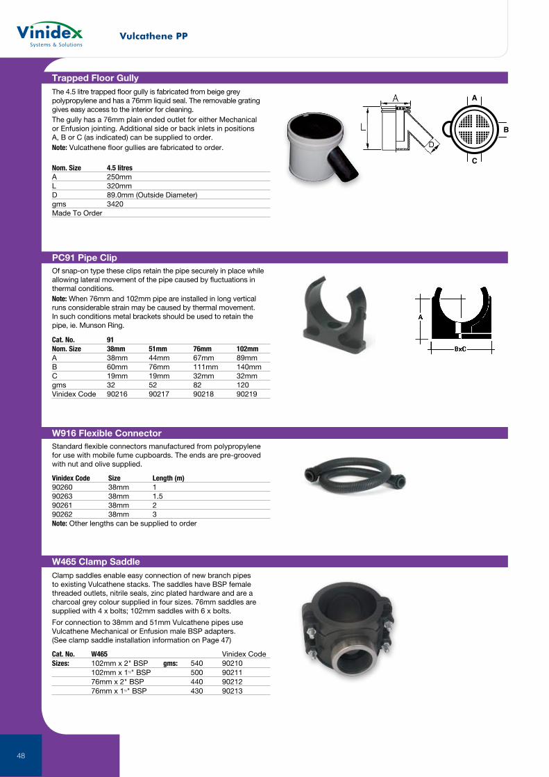
910G Dilution Recovery Trap (Glass Base)With a 4.5 litre capacity and a 76mm trap seal the 910G, with its clear base of heat resistant, borosilicate glass allows the volume of solids collected to be quickly assessed and, where necessary, cleared. It also allows the identification and recovery of valuable solids. The new 910G is supplied with a removable lid & gasket seal, both held in place by a stainless steel clamp which can be easily removed for access & maintenance. Outlet connection is 51mm, with nut & olive supplied. Dip tubes, vertical inlets, horizontal inlets and blanking off plugs should be ordered separately.
Cat. No. 910GA 208mmB 246mmC 265mmD 156mmgms 4010Vinidex Code 90257
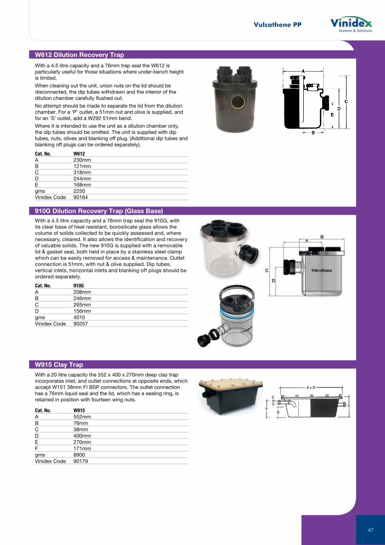
W612 Dilution Recovery Trap
Cat. No. W612A 230mmB 121mmC 318mmD 244mmE 168mmgms 2250Vinidex Code 90164
With a 4.5 litre capacity and a 76mm trap seal the W612 is particularly useful for those situations where under-bench height is limited.
When cleaning out the unit, union nuts on the lid should be disconnected, the dip tubes withdrawn and the interior of the dilution chamber carefully flushed out.
No attempt should be made to separate the lid from the dilution chamber. For a ‘P’ outlet, a 51mm nut and olive is supplied, and for an ‘S’ outlet, add a W292 51mm bend.
Where it is intended to use the unit as a dilution chamber only, the dip tubes should be omitted. The unit is supplied with dip tubes, nuts, olives and blanking off plug. (Additional dip tubes and blanking off plugs can be ordered separately).
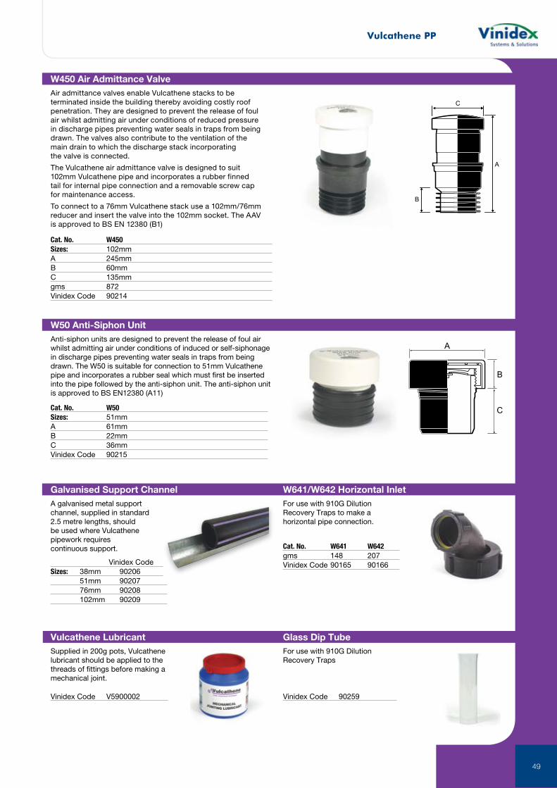
W915 Clay Trap
With a 20 litre capacity the 552 x 400 x 270mm deep clay trap incorporates inlet, and outlet connections at opposite ends, which accept W151 38mm FI BSP connectors. The outlet connection has a 76mm liquid seal and the lid, which has a sealing ring, is retained in position with fourteen wing nuts.
Cat. No. W915A 552mmB 76mmC 38mmD 400mmE 270mmF 171mmgms 8900Vinidex Code 90179
Vulcathene PP
48
W465 Clamp SaddleClamp saddles enable easy connection of new branch pipes to existing Vulcathene stacks. The saddles have BSP female threaded outlets, nitrile seals, zinc plated hardware and are a charcoal grey colour supplied in four sizes. 76mm saddles are supplied with 4 x bolts; 102mm saddles with 6 x bolts.
For connection to 38mm and 51mm Vulcathene pipes use Vulcathene Mechanical or Enfusion male BSP adapters. (See clamp saddle installation information on Page 47)
Cat. No. W465 Vinidex CodeSizes: 102mm x 2" BSP gms: 540 90210 102mm x 1½" BSP 500 90211 76mm x 2" BSP 440 90212 76mm x 1½" BSP 430 90213
PC91 Pipe ClipOf snap-on type these clips retain the pipe securely in place while allowing lateral movement of the pipe caused by fluctuations in thermal conditions.Note: When 76mm and 102mm pipe are installed in long vertical runs considerable strain may be caused by thermal movement. In such conditions metal brackets should be used to retain the pipe, ie. Munson Ring.
Cat. No. 91Nom. Size 38mm 51mm 76mm 102mmA 38mm 44mm 67mm 89mmB 60mm 76mm 111mm 140mmC 19mm 19mm 32mm 32mmgms 32 52 82 120Vinidex Code 90216 90217 90218 90219
Vinidex Code Size Length (m)90260 38mm 190263 38mm 1.590261 38mm 290262 38mm 3Note: Other lengths can be supplied to order
W916 Flexible ConnectorStandard flexible connectors manufactured from polypropylene for use with mobile fume cupboards. The ends are pre-grooved with nut and olive supplied.
Trapped Floor GullyThe 4.5 litre trapped floor gully is fabricated from beige grey polypropylene and has a 76mm liquid seal. The removable grating gives easy access to the interior for cleaning.The gully has a 76mm plain ended outlet for either Mechanical or Enfusion jointing. Additional side or back inlets in positions A, B or C (as indicated) can be supplied to order. Note: Vulcathene floor gullies are fabricated to order.
Nom. Size 4.5 litresA 250mmL 320mmD 89.0mm (Outside Diameter)gms 3420Made To Order
A
B
C
Vulcathene PP
49
C
B
A
W450 Air Admittance ValveAir admittance valves enable Vulcathene stacks to be terminated inside the building thereby avoiding costly roof penetration. They are designed to prevent the release of foul air whilst admitting air under conditions of reduced pressure in discharge pipes preventing water seals in traps from being drawn. The valves also contribute to the ventilation of the main drain to which the discharge stack incorporating the valve is connected.
The Vulcathene air admittance valve is designed to suit 102mm Vulcathene pipe and incorporates a rubber finned tail for internal pipe connection and a removable screw cap for maintenance access.
To connect to a 76mm Vulcathene stack use a 102mm/76mm reducer and insert the valve into the 102mm socket. The AAV is approved to BS EN 12380 (B1)
Cat. No. W450Sizes: 102mmA 245mmB 60mmC 135mmgms 872Vinidex Code 90214
W641/W642 Horizontal InletFor use with 910G Dilution Recovery Traps to make a horizontal pipe connection.
Galvanised Support ChannelA galvanised metal support channel, supplied in standard 2.5 metre lengths, should be used where Vulcathene pipework requires continuous support. Cat. No. W641 W642
gms 148 207Vinidex Code 90165 90166 Vinidex Code
Sizes: 38mm 90206 51mm 90207 76mm 90208 102mm 90209
A
B
C
W50 Anti-Siphon UnitAnti-siphon units are designed to prevent the release of foul air whilst admitting air under conditions of induced or self-siphonage in discharge pipes preventing water seals in traps from being drawn. The W50 is suitable for connection to 51mm Vulcathene pipe and incorporates a rubber seal which must first be inserted into the pipe followed by the anti-siphon unit. The anti-siphon unit is approved to BS EN12380 (A11)
Cat. No. W50Sizes: 51mmA 61mmB 22mmC 36mmVinidex Code 90215
Glass Dip TubeFor use with 910G Dilution Recovery Traps
Vinidex Code 90259
Vulcathene LubricantSupplied in 200g pots, Vulcathene lubricant should be applied to the threads of fittings before making a mechanical joint.
Vinidex Code V5900002
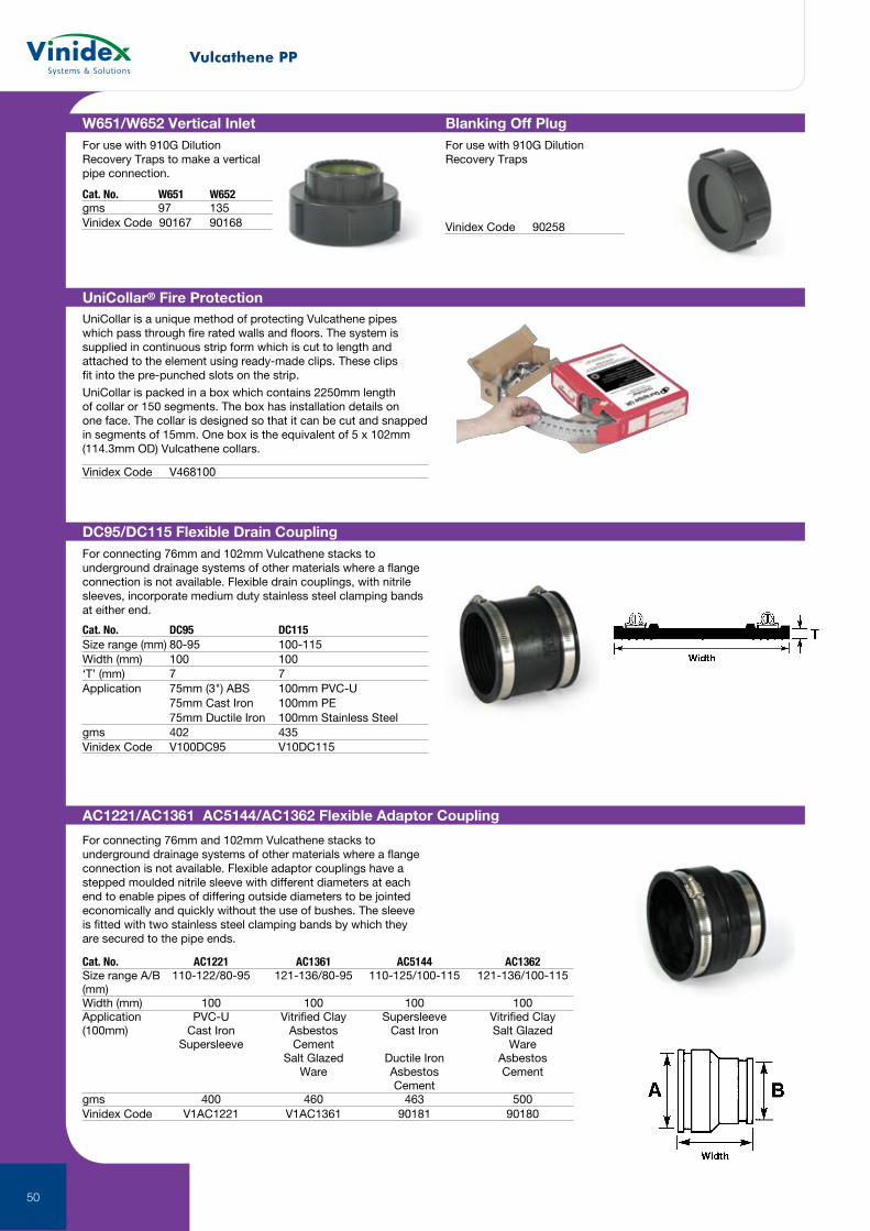
Vulcathene PP
50
Vinidex Code V468100
DC95/DC115 Flexible Drain CouplingFor connecting 76mm and 102mm Vulcathene stacks to underground drainage systems of other materials where a flange connection is not available. Flexible drain couplings, with nitrile sleeves, incorporate medium duty stainless steel clamping bands at either end.
Cat. No. DC95 DC115Size range (mm) 80-95 100-115Width (mm) 100 100‘T’ (mm) 7 7Application 75mm (3") ABS 100mm PVC-U 75mm Cast Iron 100mm PE 75mm Ductile Iron 100mm Stainless Steelgms 402 435Vinidex Code V100DC95 V10DC115
AC1221/AC1361 AC5144/AC1362 Flexible Adaptor Coupling
For connecting 76mm and 102mm Vulcathene stacks to underground drainage systems of other materials where a flange connection is not available. Flexible adaptor couplings have a stepped moulded nitrile sleeve with different diameters at each end to enable pipes of differing outside diameters to be jointed economically and quickly without the use of bushes. The sleeve is fitted with two stainless steel clamping bands by which they are secured to the pipe ends.
Cat. No. AC1221 AC1361 AC5144 AC1362Size range A/B 110-122/80-95 121-136/80-95 110-125/100-115 121-136/100-115 (mm)Width (mm) 100 100 100 100Application PVC-U Vitrified Clay Supersleeve Vitrified Clay (100mm) Cast Iron Asbestos Cast Iron Salt Glazed Supersleeve Cement Ware Salt Glazed Ductile Iron Asbestos Ware Asbestos Cement Cementgms 400 460 463 500Vinidex Code V1AC1221 V1AC1361 90181 90180
Blanking Off PlugFor use with 910G Dilution Recovery Traps
Vinidex Code 90258
W651/W652 Vertical InletFor use with 910G Dilution Recovery Traps to make a vertical pipe connection.
Cat. No. W651 W652gms 97 135Vinidex Code 90167 90168
UniCollar® Fire ProtectionUniCollar is a unique method of protecting Vulcathene pipes which pass through fire rated walls and floors. The system is supplied in continuous strip form which is cut to length and attached to the element using ready-made clips. These clips fit into the pre-punched slots on the strip.
UniCollar is packed in a box which contains 2250mm length of collar or 150 segments. The box has installation details on one face. The collar is designed so that it can be cut and snapped in segments of 15mm. One box is the equivalent of 5 x 102mm (114.3mm OD) Vulcathene collars.
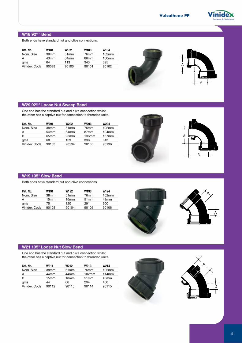
Vulcathene PP
51
W18 92½° BendBoth ends have standard nut and olive connections.
Cat. No. W181 W182 W183 W184Nom. Size 38mm 51mm 76mm 102mmA 43mm 64mm 86mm 100mmgms 64 113 343 625Vinidex Code 90099 90100 90101 90102
W29 92½° Loose Nut Sweep BendOne end has the standard nut and olive connection whilst the other has a captive nut for connection to threaded units.
Cat. No. W291 W292 W293 W294Nom. Size 38mm 51mm 76mm 102mmA 54mm 64mm 87mm 104mmB 65mm 93mm 136mm 167mmgms 68 109 338 613Vinidex Code 90133 90134 90135 90136
W19 135° Slow BendBoth ends have standard nut and olive connections.
Cat. No. W191 W192 W193 W194Nom. Size 38mm 51mm 76mm 102mmA 15mm 16mm 51mm 48mmgms 75 120 291 900Vinidex Code 90103 90104 90105 90106
W21 135° Loose Nut Slow BendOne end has the standard nut and olive connection whilst the other has a captive nut for connection to threaded units.
Cat. No. W211 W212 W213 W214Nom. Size 38mm 51mm 76mm 102mmA 44mm 44mm 102mm 114mmB 15mm 18mm 51mm 45mmgms 44 66 294 468Vinidex Code 90112 90113 90114 90115
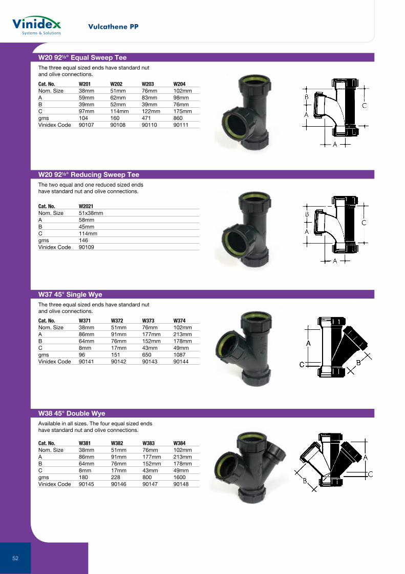
Vulcathene PP
52
W20 92½° Equal Sweep TeeThe three equal sized ends have standard nut and olive connections.
Cat. No. W201 W202 W203 W204Nom. Size 38mm 51mm 76mm 102mmA 59mm 62mm 83mm 98mmB 39mm 52mm 39mm 76mmC 97mm 114mm 122mm 175mmgms 104 160 471 860Vinidex Code 90107 90108 90110 90111
W20 92½° Reducing Sweep TeeThe two equal and one reduced sized ends have standard nut and olive connections.
Cat. No. W2021 Nom. Size 51x38mm A 58mm B 45mm C 114mm gms 146Vinidex Code 90109
W37 45° Single WyeThe three equal sized ends have standard nut and olive connections.
Cat. No. W371 W372 W373 W374Nom. Size 38mm 51mm 76mm 102mmA 86mm 91mm 177mm 213mmB 64mm 76mm 152mm 178mmC 8mm 17mm 43mm 49mmgms 96 151 650 1087Vinidex Code 90141 90142 90143 90144
W38 45° Double WyeAvailable in all sizes. The four equal sized ends have standard nut and olive connections.
Cat. No. W381 W382 W383 W384Nom. Size 38mm 51mm 76mm 102mmA 86mm 91mm 177mm 213mmB 64mm 76mm 152mm 178mmC 8mm 17mm 43mm 49mmgms 180 228 800 1600Vinidex Code 90145 90146 90147 90148
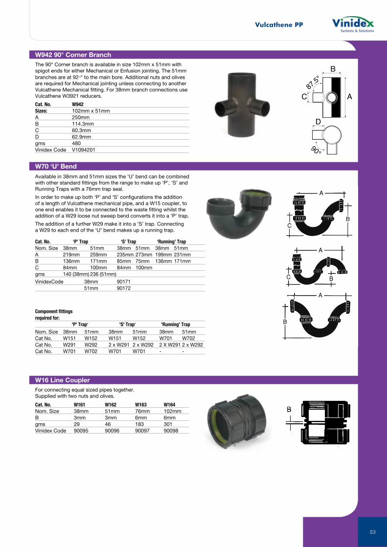
Vulcathene PP
53
W16 Line CouplerFor connecting equal sized pipes together. Supplied with two nuts and olives.
Cat. No. W161 W162 W163 W164Nom. Size 38mm 51mm 76mm 102mmB 3mm 3mm 6mm 6mmgms 29 46 183 301 Vinidex Code 90095 90096 90097 90098
W70 ‘U’ Bend
Available in 38mm and 51mm sizes the ‘U’ bend can be combined with other standard fittings from the range to make up ‘P’, ‘S’ and Running Traps with a 76mm trap seal.
In order to make up both ‘P’ and ‘S’ configurations the addition of a length of Vulcathene mechanical pipe, and a W15 coupler, to one end enables it to be connected to the waste fitting whilst the addition of a W29 loose nut sweep bend converts it into a ‘P’ trap.
The addition of a further W29 make it into a ‘S’ trap. Connecting a W29 to each end of the ‘U’ bend makes up a running trap.
Cat. No. ‘P’ Trap ‘S’ Trap ‘Running’ TrapNom. Size 38mm 51mm 38mm 51mm 38mm 51mmA 219mm 259mm 235mm 273mm 199mm 231mmB 136mm 171mm 85mm 75mm 136mm 171mmC 84mm 100mm 84mm 100mmgms 140 (38mm) 236 (51mm)
Component fittings required for: 'P' Trap* 'S' Trap* 'Running' TrapNom. Size 38mm 51mm 38mm 51mm 38mm 51mmCat No. W151 W152 W151 W152 W701 W702Cat No. W291 W292 2 x W291 2 x W292 2 X W291 2 x W292Cat No. W701 W702 W701 W701 - -
B
AC
D
90°
87.5°
W942 90° Corner BranchThe 90° Corner branch is available in size 102mm x 51mm with spigot ends for either Mechanical or Enfusion jointing. The 51mm branches are at 92½° to the main bore. Additional nuts and olives are required for Mechanical jointing unless connecting to another Vulcathene Mechanical fitting. For 38mm branch connections use Vulcathene W3921 reducers.
Cat. No. W942Sizes: 102mm x 51mmA 250mmB 114.3mmC 60.3mmD 62.9mmgms 480Vinidex Code V1094201
VinidexCode 38mm 90171 51mm 90172
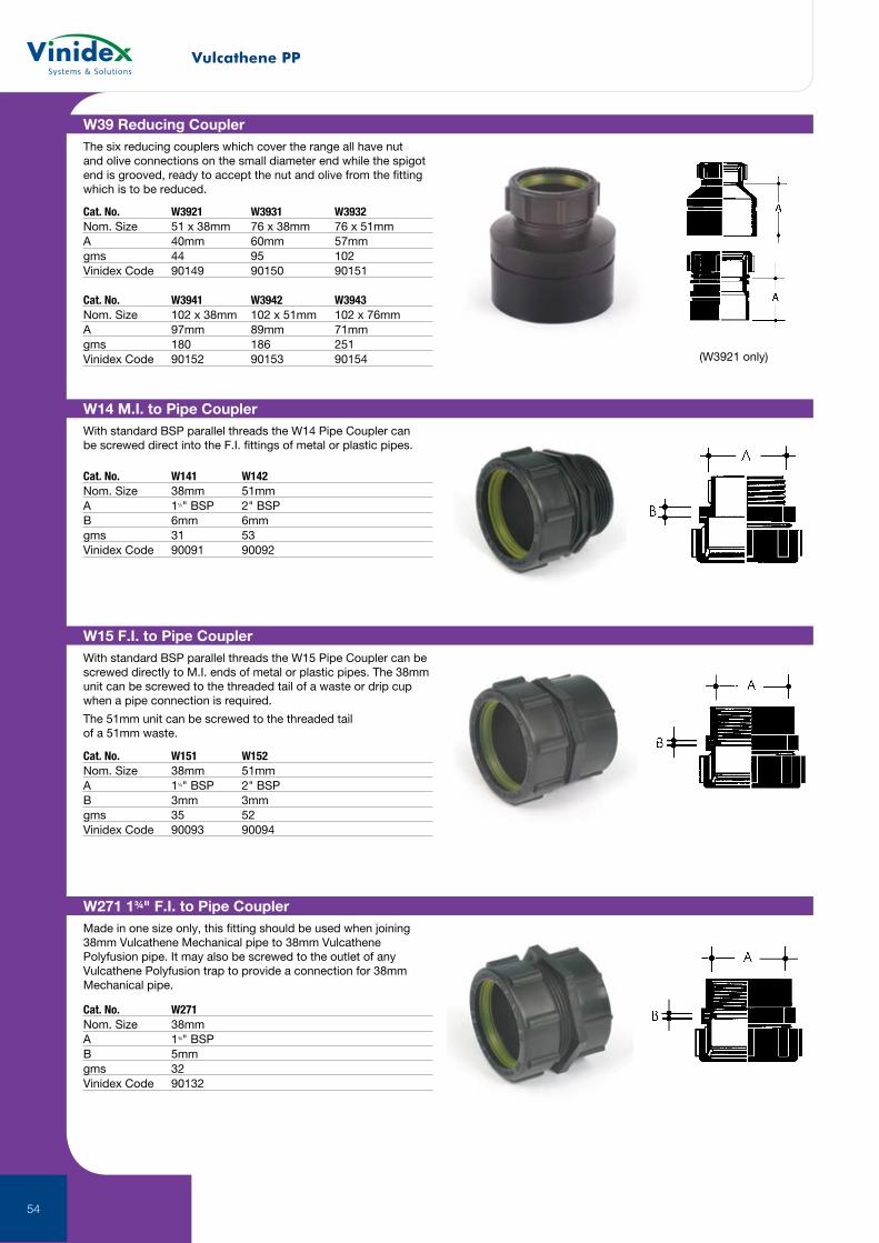
Vulcathene PP
54
W15 F.I. to Pipe CouplerWith standard BSP parallel threads the W15 Pipe Coupler can be screwed directly to M.I. ends of metal or plastic pipes. The 38mm unit can be screwed to the threaded tail of a waste or drip cup when a pipe connection is required.
The 51mm unit can be screwed to the threaded tail of a 51mm waste.
Cat. No. W151 W152Nom. Size 38mm 51mmA 1½" BSP 2" BSPB 3mm 3mmgms 35 52Vinidex Code 90093 90094
W14 M.I. to Pipe CouplerWith standard BSP parallel threads the W14 Pipe Coupler can be screwed direct into the F.I. fittings of metal or plastic pipes.
Cat. No. W141 W142Nom. Size 38mm 51mmA 1½" BSP 2" BSPB 6mm 6mmgms 31 53Vinidex Code 90091 90092
W39 Reducing CouplerThe six reducing couplers which cover the range all have nut and olive connections on the small diameter end while the spigot end is grooved, ready to accept the nut and olive from the fitting which is to be reduced.
Cat. No. W3921 W3931 W3932Nom. Size 51 x 38mm 76 x 38mm 76 x 51mmA 40mm 60mm 57mmgms 44 95 102Vinidex Code 90149 90150 90151
Cat. No. W3941 W3942 W3943Nom. Size 102 x 38mm 102 x 51mm 102 x 76mmA 97mm 89mm 71mmgms 180 186 251Vinidex Code 90152 90153 90154 (W3921 only)
W271 1¾" F.I. to Pipe CouplerMade in one size only, this fitting should be used when joining 38mm Vulcathene Mechanical pipe to 38mm Vulcathene Polyfusion pipe. It may also be screwed to the outlet of any Vulcathene Polyfusion trap to provide a connection for 38mm Mechanical pipe.
Cat. No. W271Nom. Size 38mmA 1¾" BSPB 5mmgms 32Vinidex Code 90132
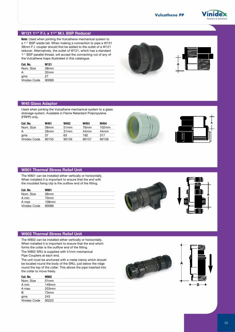
Vulcathene PP
55
W801 Thermal Stress Relief UnitThe W801 can be installed either vertically or horizontally. When installed it is important to ensure that the end with the moulded fixing clip is the outflow end of the fitting.
Cat. No. W801Nom. Size 38mmA min 70mmA max 108mmVinidex Code 90088
W45 Glass AdaptorUsed when jointing the Vulcathene mechanical system to a glass drainage system. Available in Flame Retardant Polpropylene (FRPP) only.
Cat. No. W451 W452 W453 W454Nom. Size 38mm 51mm 76mm 102mmA 28mm 31mm 44mm 44mmgms 37 63 192 317Vinidex Code 90155 90156 90157 90158
W121 1¼" F.I. x 1½" M.I. BSP ReducerNote: Used when jointing the Vulcathene mechanical system to a 1¼" BSP waste tail. When making a connection to pipe a W151 38mm F.I. coupler should first be added to the outlet of a W121 reducer. Alternatively, the outlet of W121, which has a standard 1½" BSP parallel thread, will accept the connecting nut of any of the Vulcathene traps illustrated in this catalogue.
Cat. No. W121Nom. Size 38mmA 32mmgms 27Vinidex Code 90089
W802 Thermal Stress Relief UnitThe W802 can be installed either vertically or horizontally. When installed it is important to ensure that the end which forms the collar is the outflow end of the fitting.The W802 SRU is supplied with 51mm mechanical Pipe Couplers at each end.The unit must be anchored with a metal clamp which should be located round the body of the SRU, just below the ridge round the top of the collar. This allows the pipe inserted into the collar to move freely.
Cat. No. W802Nom. Size 51mmA min 149mmA max 203mmB 73mmgms 243Vinidex Code 90222
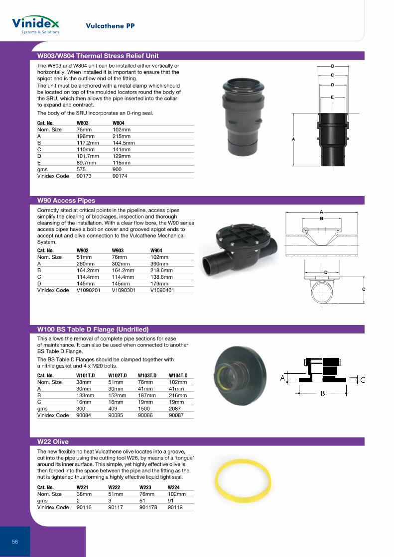
Vulcathene PP
56
W903/W904 Access PipeW100 BS Table D Flange (Undrilled)This allows the removal of complete pipe sections for ease of maintenance. It can also be used when connected to another BS Table D Flange.
The BS Table D Flanges should be clamped together with a nitrile gasket and 4 x M20 bolts.
Cat. No. W101T.D W102T.D W103T.D W104T.DNom. Size 38mm 51mm 76mm 102mmA 30mm 30mm 41mm 41mmB 133mm 152mm 187mm 216mmC 16mm 16mm 19mm 19mmgms 300 409 1500 2087Vinidex Code 90084 90085 90086 90087
W803/W804 Thermal Stress Relief UnitThe W803 and W804 unit can be installed either vertically or horizontally. When installed it is important to ensure that the spigot end is the outflow end of the fitting.The unit must be anchored with a metal clamp which should be located on top of the moulded locators round the body of the SRU, which then allows the pipe inserted into the collar to expand and contract.
The body of the SRU incorporates an 0-ring seal.
Cat. No. W803 W804Nom. Size 76mm 102mmA 196mm 215mmB 117.2mm 144.5mmC 110mm 141mmD 101.7mm 129mmE 89.7mm 115mmgms 575 900Vinidex Code 90173 90174
W90 Access PipesCorrectly sited at critical points in the pipeline, access pipes simplify the clearing of blockages, inspection and thorough cleansing of the installation. With a clear flow bore, the W90 series access pipes have a bolt on cover and grooved spigot ends to accept nut and olive connection to the Vulcathene Mechanical System.
Cat. No. W902 W903 W904Nom. Size 51mm 76mm 102mmA 260mm 302mm 390mmB 164.2mm 164.2mm 218.6mmC 114.4mm 114.4mm 138.8mmD 145mm 145mm 179mmVinidex Code V1090201 V1090301 V1090401
W22 OliveThe new flexible no heat Vulcathene olive locates into a groove, cut into the pipe using the cutting tool W26, by means of a ‘tongue’ around its inner surface. This simple, yet highly effective olive is then forced into the space between the pipe and the fitting as the nut is tightened thus forming a highly effective liquid tight seal.
Cat. No. W221 W222 W223 W224Nom. Size 38mm 51mm 76mm 102mmgms 2 3 51 91Vinidex Code 90116 90117 901178 90119
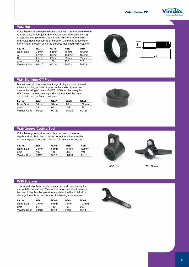
Vulcathene PP
57
W36 SpannerThis moulded polycarbonate spanner is made specifically for use with the Vulcathene Mechanical range and should always be used to tighten the Vulcathene nuts as it will not distort or damage the nuts in the process of achieving a secure joint.
Cat. No. W361 W362 W363 W364Nom. Size 38mm 51mm 76mm 102mmgms 81 110 199 269Vinidex Code 90137 90138 90139 90140
W24 Blanking-Off PlugMade to suit all pipe sizes, blanking-off plugs should be used where a rodding point is required in the waste pipe run and also for blanking off inlets of a W612 Dilution Recovery Trap. With its own tapered sealing surface, it replaces the olive, and is held into the fitting by the nut.
Cat. No. W241 W242 W243 W244Nom. Size 38mm 51mm 76mm 102mmgms 38 64 109 196Vinidex Code 90124 90122 90126 90127
W26 Groove Cutting ToolVulcathene grooving tools enable a groove, of the exact depth and width, to be cut in the correct location from the end of the pipe where the mechanical olive is then located.
Cat. No. W261 W262 W263 W264Nom. Size 38mm 51mm 76mm 102mmgms 100 146 368 719Vinidex Code 90128 90129 90130 90131
38/51mm 76/102mm
W23 NutVulcathene nuts are used in conjunction with the Vulcathene olive to make a watertight joint. Every Vulcathene Mechanical fitting is supplied complete with Vulcathene nuts. We recommend that Vulcathene lubricant is smeared on the thread to facilitate tightening of the joint using the purpose-designed W36 spanner.
Cat. No. W231 W232 W233 W234Nom. Size 38mm 51mm 76mm 102mmA 67mm 83mm 134mm 162mmB 21mm 25mm 33mm 35mmgms 58 100 250 520Vinidex Code 90120 90121 90122 90123
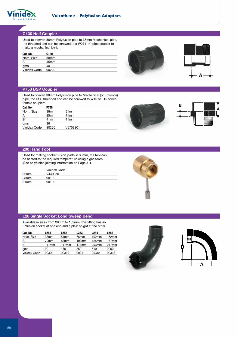
58
C130 Half CouplerUsed to convert 38mm Polyfusion pipe to 38mm Mechanical pipe, the threaded end can be screwed to a W271 1¾" pipe coupler to make a mechanical joint.
Cat. No. C130Nom. Size 38mmA 45mmgms 40Vinidex Code 90220
P758 BSP CouplerUsed to convert 38mm Polyfusion pipe to Mechanical (or Enfusion) pipe, the BSP threaded end can be screwed to W15 or L15 series female couplers.Cat. No. P758Nom. Size 38mm 51mmA 35mm 41mmB 41mm 41mm gms 36Vinidex Code 90256 V5758201
Vinidex Code32mm V44005038mm 9019251mm 90193
200 Hand ToolUsed for making socket fusion joints in 38mm, the tool can be heated to the required temperature using a gas torch. (See polyfusion jointing information on Page 51).
L28 Single Socket Long Sweep BendAvailable in sizes from 38mm to 152mm, this fitting has an Enfusion socket at one end and a plain spigot at the other.
Cat. No. L281 L282 L283 L284 L286Nom. Size 38mm 51mm 76mm 102mm 152mmA 70mm 83mm 103mm 125mm 167mmB 117mm 117mm 171mm 203mm 247mmgms 90 170 350 510 2000Vinidex Code 90309 90310 90311 90312 90313
Vulcathene – Polyfusion Adaptors
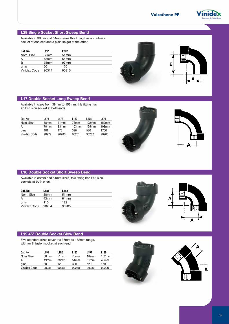
Vulcathene PP
59
L29 Single Socket Short Sweep BendAvailable in 38mm and 51mm sizes this fitting has an Enfusion socket at one end and a plain spigot at the other.
Cat. No. L291 L292Nom. Size 38mm 51mmA 43mm 64mmB 75mm 97mmgms 90 120Vinidex Code 90314 90315
L17 Double Socket Long Sweep BendAvailable in sizes from 38mm to 152mm, this fitting has an Enfusion socket at both ends.
Cat. No. L171 L172 L173 L174 L176Nom. Size 38mm 51mm 76mm 102mm 152mmA 70mm 83mm 103mm 125mm 198mmgms 101 170 390 530 1760Vinidex Code 90279 90280 90281 90282 90283
L18 Double Socket Short Sweep BendAvailable in 38mm and 51mm sizes, this fitting has Enfusion sockets at both ends.
Cat. No. L181 L182Nom. Size 38mm 51mmA 43mm 64mmgms 115 172Vinidex Code 90284 90285
L19 45° Double Socket Slow BendFive standard sizes cover the 38mm to 152mm range, with an Enfusion socket at each end.
Cat. No. L191 L192 L193 L194 L196Nom. Size 38mm 51mm 76mm 102mm 152mmA 19mm 38mm 51mm 51mm 43mmgms 80 120 300 520 1500Vinidex Code 90286 90287 90288 90289 90290
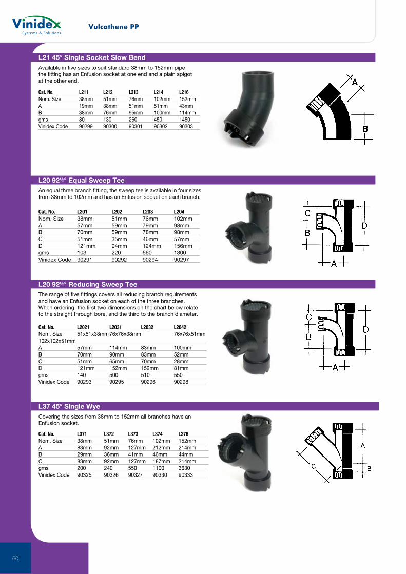
Vulcathene PP
60
L21 45° Single Socket Slow BendAvailable in five sizes to suit standard 38mm to 152mm pipe the fitting has an Enfusion socket at one end and a plain spigot at the other end.
Cat. No. L211 L212 L213 L214 L216Nom. Size 38mm 51mm 76mm 102mm 152mmA 19mm 38mm 51mm 51mm 43mmB 38mm 76mm 95mm 100mm 114mmgms 80 130 260 450 1450Vinidex Code 90299 90300 90301 90302 90303
L20 92½° Equal Sweep TeeAn equal three branch fitting, the sweep tee is available in four sizes from 38mm to 102mm and has an Enfusion socket on each branch.
Cat. No. L201 L202 L203 L204Nom. Size 38mm 51mm 76mm 102mmA 57mm 59mm 79mm 98mmB 70mm 59mm 78mm 98mmC 51mm 35mm 46mm 57mmD 121mm 94mm 124mm 156mmgms 103 220 560 1300Vinidex Code 90291 90292 90294 90297
L20 92½° Reducing Sweep TeeThe range of five fittings covers all reducing branch requirements and have an Enfusion socket on each of the three branches. When ordering, the first two dimensions on the chart below relate to the straight through bore, and the third to the branch diameter.
Cat. No. L2021 L2031 L2032 L2042Nom. Size 51x51x38mm 76x76x38mm 76x76x51mm 102x102x51mmA 57mm 114mm 83mm 100mmB 70mm 90mm 83mm 52mmC 51mm 65mm 70mm 28mmD 121mm 152mm 152mm 81mmgms 140 500 510 550 Vinidex Code 90293 90295 90296 90298
L37 45° Single WyeCovering the sizes from 38mm to 152mm all branches have an Enfusion socket.
Cat. No. L371 L372 L373 L374 L376Nom. Size 38mm 51mm 76mm 102mm 152mmA 83mm 92mm 127mm 212mm 214mmB 29mm 36mm 41mm 46mm 44mmC 83mm 92mm 127mm 187mm 214mmgms 200 240 550 1100 3630Vinidex Code 90325 90326 90327 90330 90333
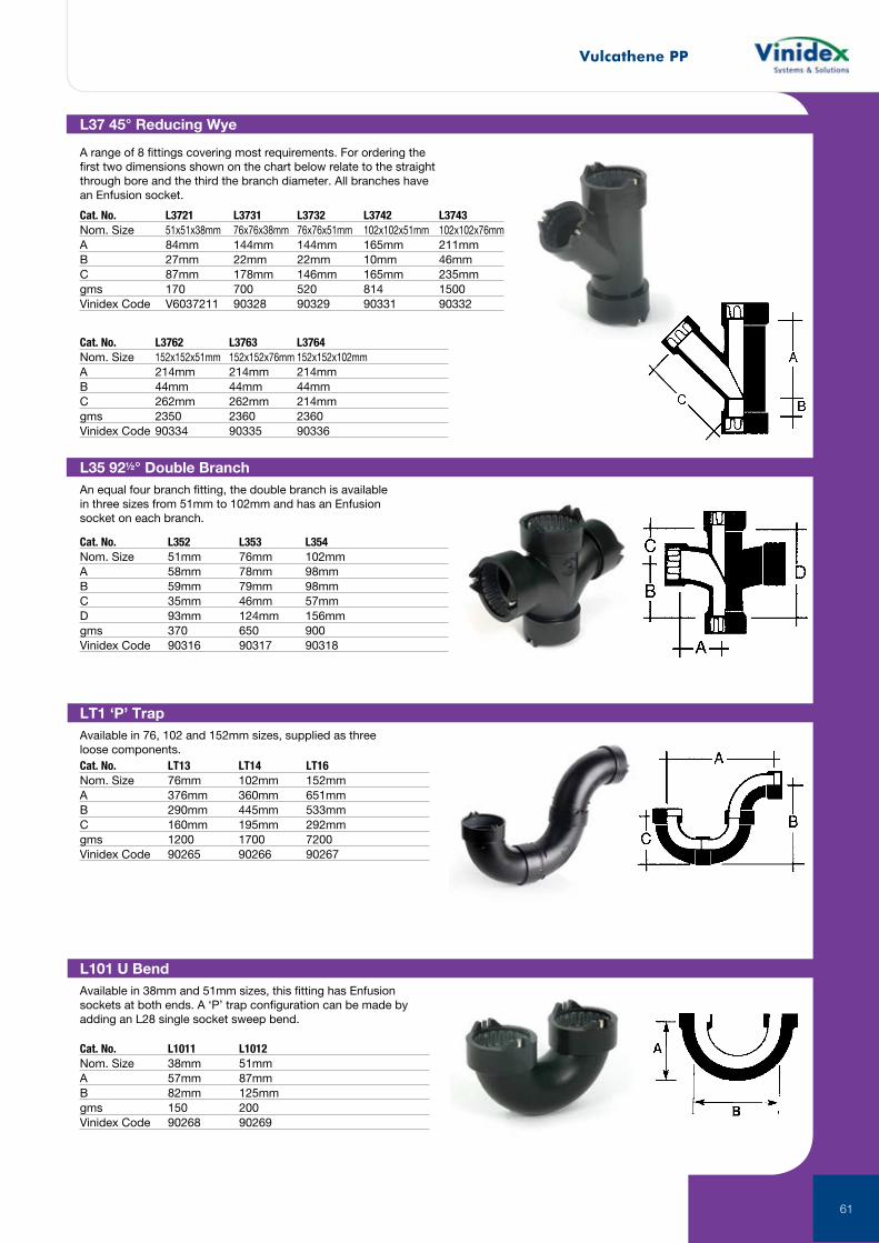
Vulcathene PP
61
L37 45° Reducing Wye
A range of 8 fittings covering most requirements. For ordering the first two dimensions shown on the chart below relate to the straight through bore and the third the branch diameter. All branches have an Enfusion socket.
Cat. No. L3721 L3731 L3732 L3742 L3743Nom. Size 51x51x38mm 76x76x38mm 76x76x51mm 102x102x51mm 102x102x76mmA 84mm 144mm 144mm 165mm 211mmB 27mm 22mm 22mm 10mm 46mmC 87mm 178mm 146mm 165mm 235mmgms 170 700 520 814 1500Vinidex Code V6037211 90328 90329 90331 90332
Cat. No. L3762 L3763 L3764Nom. Size 152x152x51mm 152x152x76mm 152x152x102mmA 214mm 214mm 214mmB 44mm 44mm 44mmC 262mm 262mm 214mmgms 2350 2360 2360Vinidex Code 90334 90335 90336
L35 92½° Double BranchAn equal four branch fitting, the double branch is available in three sizes from 51mm to 102mm and has an Enfusion socket on each branch.
Cat. No. L352 L353 L354Nom. Size 51mm 76mm 102mmA 58mm 78mm 98mmB 59mm 79mm 98mmC 35mm 46mm 57mmD 93mm 124mm 156mmgms 370 650 900Vinidex Code 90316 90317 90318
L101 U BendAvailable in 38mm and 51mm sizes, this fitting has Enfusion sockets at both ends. A ‘P’ trap configuration can be made by adding an L28 single socket sweep bend.
Cat. No. L1011 L1012Nom. Size 38mm 51mmA 57mm 87mmB 82mm 125mmgms 150 200Vinidex Code 90268 90269
LT1 ‘P’ TrapAvailable in 76, 102 and 152mm sizes, supplied as three loose components.Cat. No. LT13 LT14 LT16Nom. Size 76mm 102mm 152mmA 376mm 360mm 651mmB 290mm 445mm 533mmC 160mm 195mm 292mmgms 1200 1700 7200Vinidex Code 90265 90266 90267
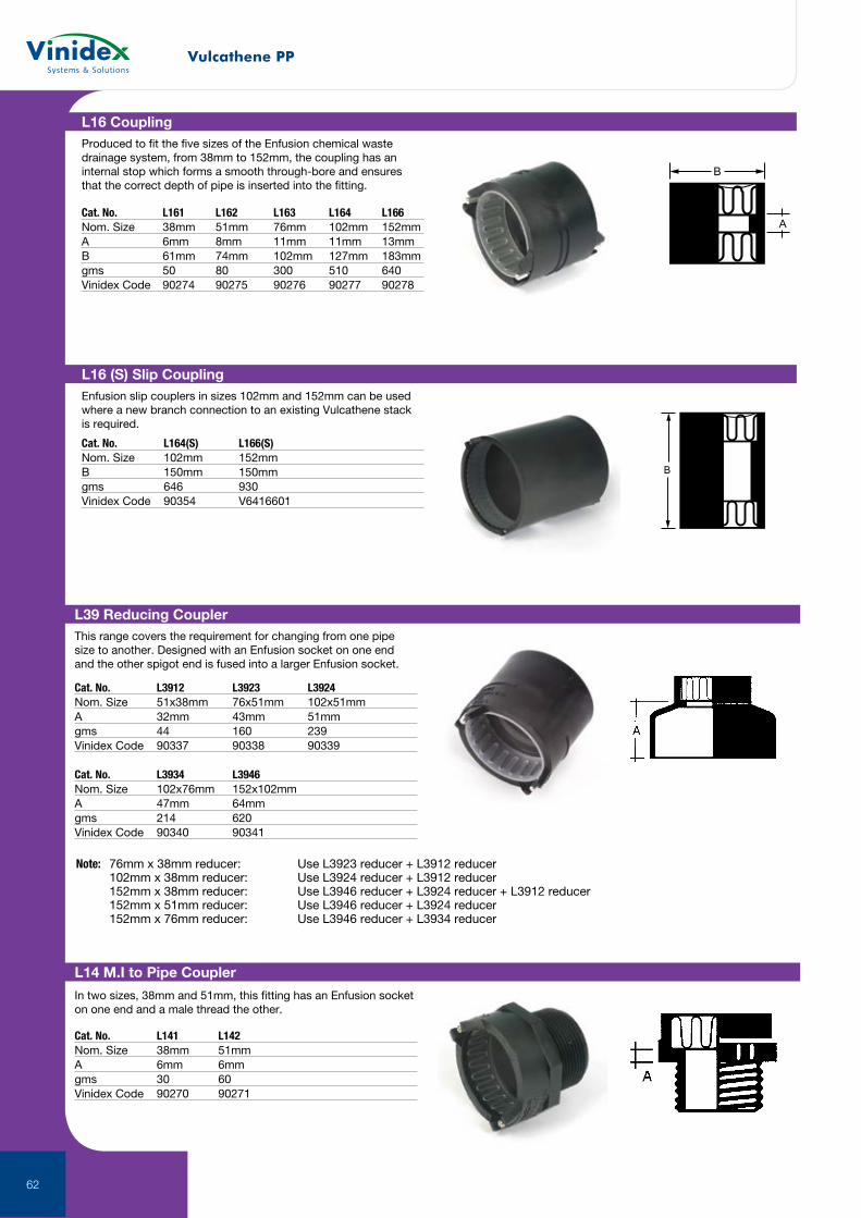
Vulcathene PP
62
A
B
B B
L16 CouplingProduced to fit the five sizes of the Enfusion chemical waste drainage system, from 38mm to 152mm, the coupling has an internal stop which forms a smooth through-bore and ensures that the correct depth of pipe is inserted into the fitting.
Cat. No. L161 L162 L163 L164 L166Nom. Size 38mm 51mm 76mm 102mm 152mmA 6mm 8mm 11mm 11mm 13mmB 61mm 74mm 102mm 127mm 183mmgms 50 80 300 510 640Vinidex Code 90274 90275 90276 90277 90278
A
B
B B
L16 (S) Slip CouplingEnfusion slip couplers in sizes 102mm and 152mm can be used where a new branch connection to an existing Vulcathene stack is required.
Cat. No. L164(S) L166(S)Nom. Size 102mm 152mmB 150mm 150mmgms 646 930Vinidex Code 90354 V6416601
L14 M.I to Pipe Coupler
In two sizes, 38mm and 51mm, this fitting has an Enfusion socket on one end and a male thread the other.
Cat. No. L141 L142Nom. Size 38mm 51mmA 6mm 6mmgms 30 60Vinidex Code 90270 90271
L39 Reducing CouplerThis range covers the requirement for changing from one pipe size to another. Designed with an Enfusion socket on one end and the other spigot end is fused into a larger Enfusion socket.
Cat. No. L3912 L3923 L3924Nom. Size 51x38mm 76x51mm 102x51mmA 32mm 43mm 51mmgms 44 160 239Vinidex Code 90337 90338 90339
Cat. No. L3934 L3946Nom. Size 102x76mm 152x102mmA 47mm 64mmgms 214 620Vinidex Code 90340 90341
Note: 76mm x 38mm reducer: Use L3923 reducer + L3912 reducer 102mm x 38mm reducer: Use L3924 reducer + L3912 reducer 152mm x 38mm reducer: Use L3946 reducer + L3924 reducer + L3912 reducer 152mm x 51mm reducer: Use L3946 reducer + L3924 reducer 152mm x 76mm reducer: Use L3946 reducer + L3934 reducer
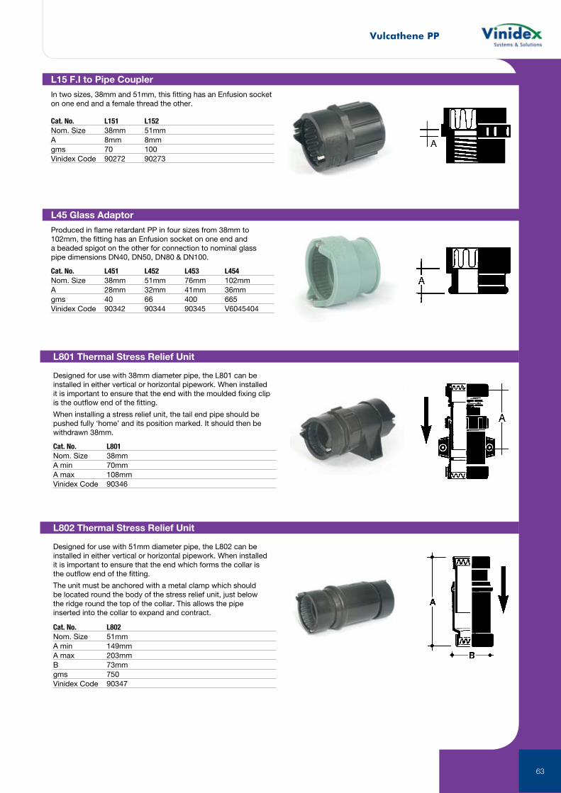
Vulcathene PP
63
L15 F.I to Pipe Coupler
In two sizes, 38mm and 51mm, this fitting has an Enfusion socket on one end and a female thread the other.
Cat. No. L151 L152Nom. Size 38mm 51mmA 8mm 8mmgms 70 100Vinidex Code 90272 90273
L45 Glass Adaptor
Produced in flame retardant PP in four sizes from 38mm to 102mm, the fitting has an Enfusion socket on one end and a beaded spigot on the other for connection to nominal glass pipe dimensions DN40, DN50, DN80 & DN100.
Cat. No. L451 L452 L453 L454Nom. Size 38mm 51mm 76mm 102mmA 28mm 32mm 41mm 36mmgms 40 66 400 665Vinidex Code 90342 90344 90345 V6045404
L801 Thermal Stress Relief Unit
Designed for use with 38mm diameter pipe, the L801 can be installed in either vertical or horizontal pipework. When installed it is important to ensure that the end with the moulded fixing clip is the outflow end of the fitting.
When installing a stress relief unit, the tail end pipe should be pushed fully ‘home’ and its position marked. It should then be withdrawn 38mm.
Cat. No. L801Nom. Size 38mmA min 70mmA max 108mmVinidex Code 90346
L802 Thermal Stress Relief Unit
Designed for use with 51mm diameter pipe, the L802 can be installed in either vertical or horizontal pipework. When installed it is important to ensure that the end which forms the collar is the outflow end of the fitting.
The unit must be anchored with a metal clamp which should be located round the body of the stress relief unit, just below the ridge round the top of the collar. This allows the pipe inserted into the collar to expand and contract.
Cat. No. L802Nom. Size 51mmA min 149mmA max 203mmB 73mmgms 750Vinidex Code 90347
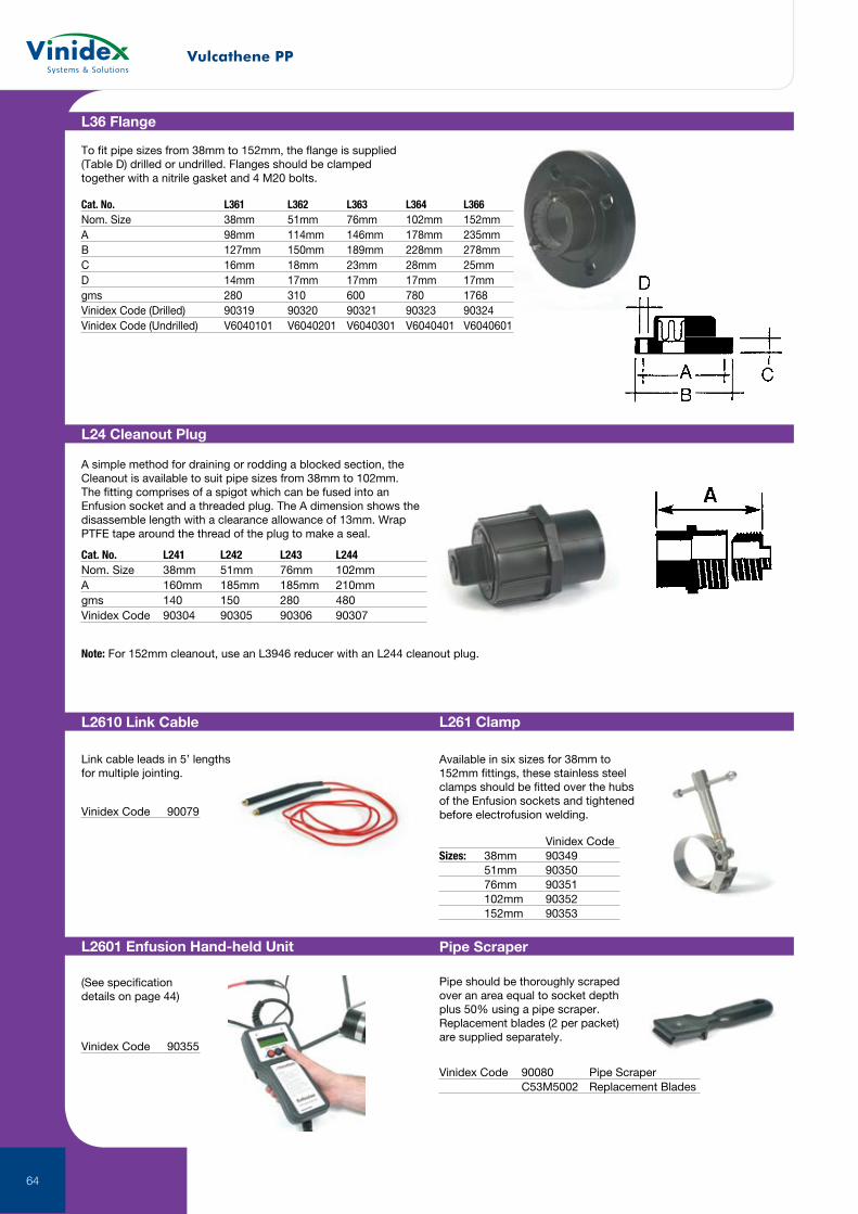
Vulcathene PP
64
L36 Flange
To fit pipe sizes from 38mm to 152mm, the flange is supplied (Table D) drilled or undrilled. Flanges should be clamped together with a nitrile gasket and 4 M20 bolts.
Cat. No. L361 L362 L363 L364 L366Nom. Size 38mm 51mm 76mm 102mm 152mmA 98mm 114mm 146mm 178mm 235mmB 127mm 150mm 189mm 228mm 278mmC 16mm 18mm 23mm 28mm 25mmD 14mm 17mm 17mm 17mm 17mmgms 280 310 600 780 1768Vinidex Code (Drilled) 90319 90320 90321 90323 90324Vinidex Code (Undrilled) V6040101 V6040201 V6040301 V6040401 V6040601
L24 Cleanout Plug
A simple method for draining or rodding a blocked section, the Cleanout is available to suit pipe sizes from 38mm to 102mm. The fitting comprises of a spigot which can be fused into an Enfusion socket and a threaded plug. The A dimension shows the disassemble length with a clearance allowance of 13mm. Wrap PTFE tape around the thread of the plug to make a seal.
Note: For 152mm cleanout, use an L3946 reducer with an L244 cleanout plug.
Cat. No. L241 L242 L243 L244Nom. Size 38mm 51mm 76mm 102mmA 160mm 185mm 185mm 210mmgms 140 150 280 480Vinidex Code 90304 90305 90306 90307
L2610 Link Cable L261 Clamp
Pipe ScraperL2601 Enfusion Hand-held Unit
Link cable leads in 5’ lengths for multiple jointing.
Available in six sizes for 38mm to 152mm fittings, these stainless steel clamps should be fitted over the hubs of the Enfusion sockets and tightened before electrofusion welding.
Vinidex CodeSizes: 38mm 90349 51mm 90350 76mm 90351 102mm 90352 152mm 90353
Vinidex Code 90079
Pipe should be thoroughly scraped over an area equal to socket depth plus 50% using a pipe scraper. Replacement blades (2 per packet) are supplied separately.
(See specification details on page 44)
Vinidex Code 90355
Vinidex Code 90080 Pipe Scraper C53M5002 Replacement Blades
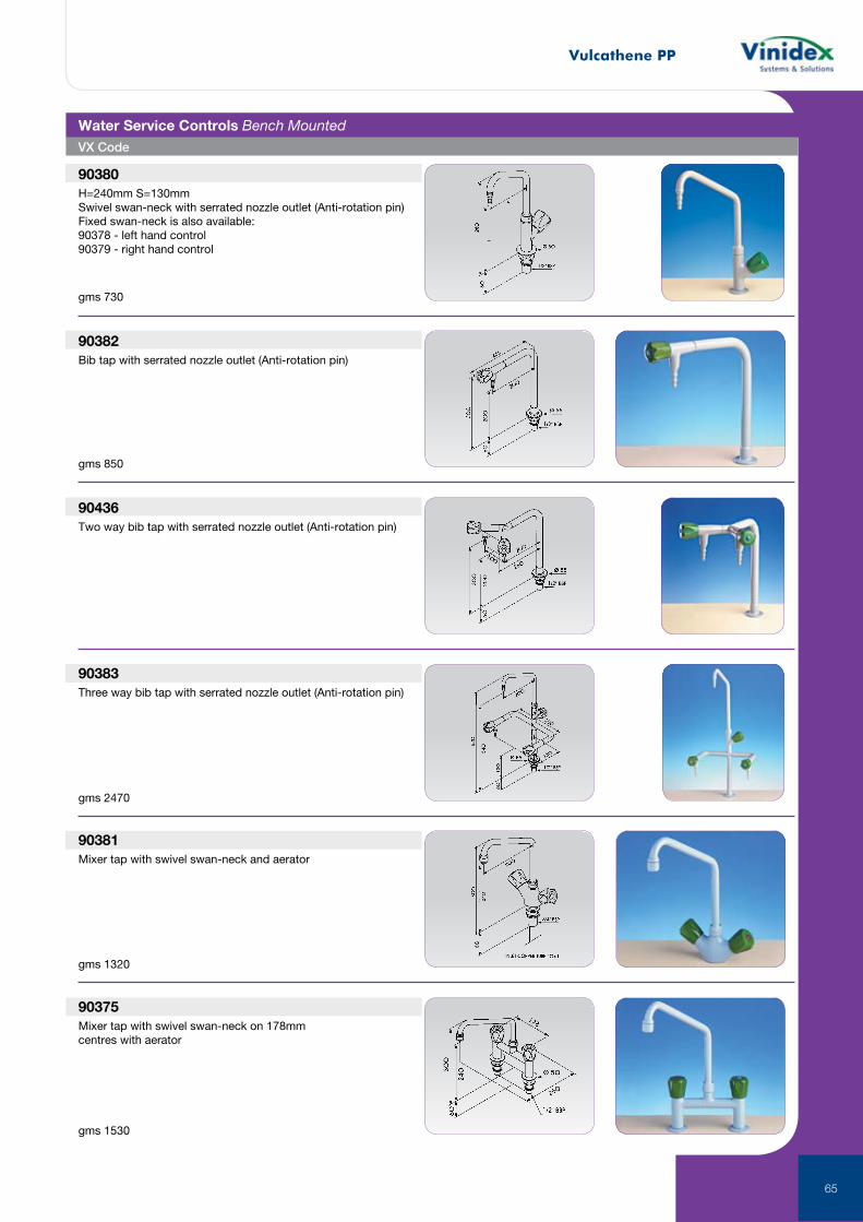
Vulcathene PP
65
90380H=240mm S=130mmSwivel swan-neck with serrated nozzle outlet (Anti-rotation pin)Fixed swan-neck is also available:90378 - left hand control90379 - right hand control
90382Bib tap with serrated nozzle outlet (Anti-rotation pin)
90436Two way bib tap with serrated nozzle outlet (Anti-rotation pin)
90383Three way bib tap with serrated nozzle outlet (Anti-rotation pin)
90381Mixer tap with swivel swan-neck and aerator
90375Mixer tap with swivel swan-neck on 178mm centres with aerator
Water Service Controls Bench Mounted
gms 730
gms 850
gms 2470
gms 1320
gms 1530
VX Code
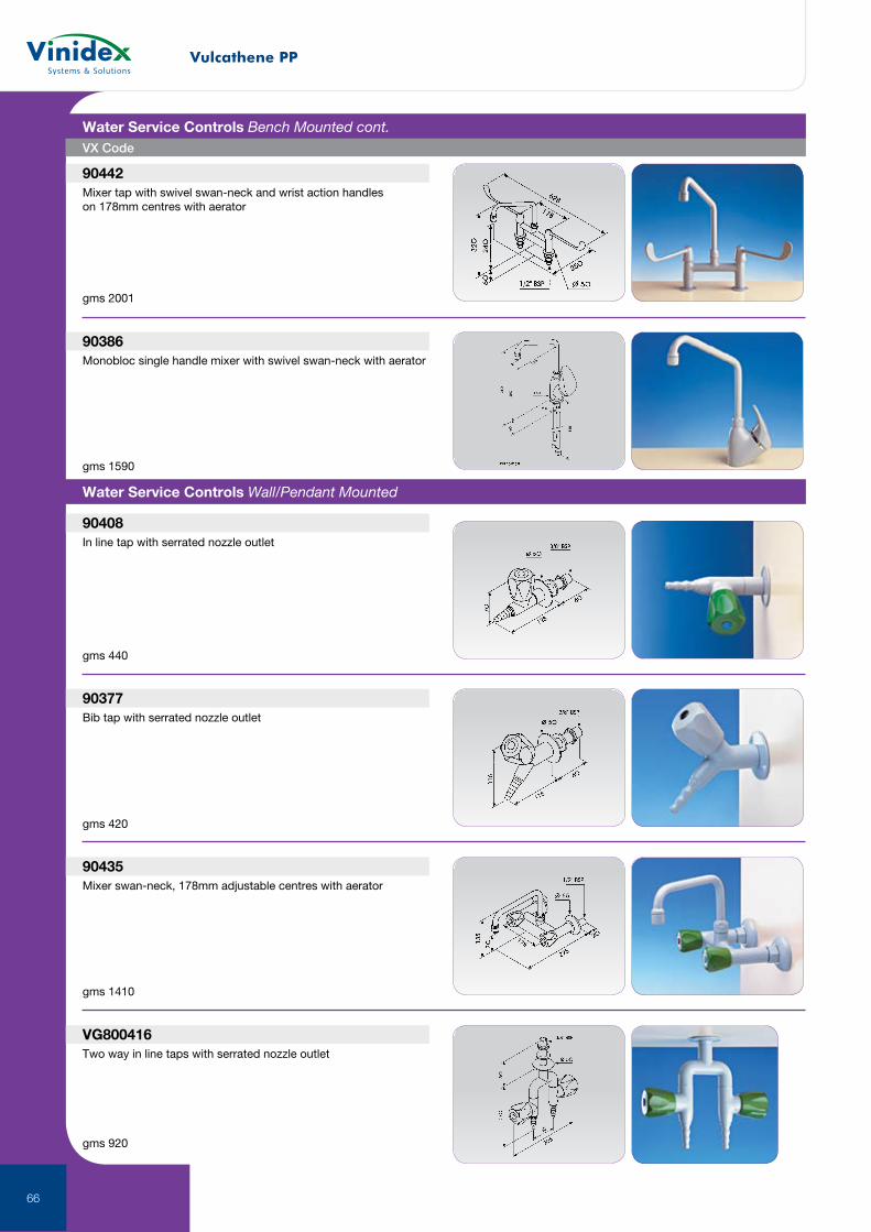
Vulcathene PP
66
90442Mixer tap with swivel swan-neck and wrist action handles on 178mm centres with aerator
90386Monobloc single handle mixer with swivel swan-neck with aerator
90408In line tap with serrated nozzle outlet
90377Bib tap with serrated nozzle outlet
90435Mixer swan-neck, 178mm adjustable centres with aerator
VG800416Two way in line taps with serrated nozzle outlet
Water Service Controls Wall/Pendant Mounted
gms 2001
gms 1590
gms 440
gms 420
gms 1410
gms 920
VX Code
Water Service Controls Bench Mounted cont.
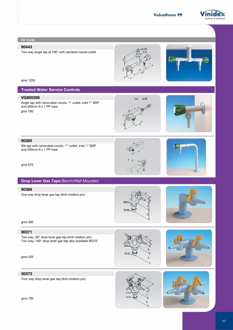
Vulcathene PP
67
90443Two way angle tap at 180° with serrated nozzle outlet
VG800298Angle tap with removable nozzle, ½" outlet, inlet ¼" BSP and 500mm 8 x 1 PP tube
90385Bib tap with removable nozzle, ½" outlet, inlet ¼" BSP and 500mm 8 x 1 PP tube
90369One way drop lever gas tap (Anti-rotation pin)
90371Two way, 90° drop lever gas tap (Anti-rotation pin)Two way, 180° drop lever gas tap also available 90370
Treated Water Service Controls
Drop Lever Gas Taps Bench/Wall Mounted
gms 1220
gms 180
gms 570
gms 300
gms 420
90372Four way drop lever gas tap (Anti-rotation pin)
gms 700
VX Code
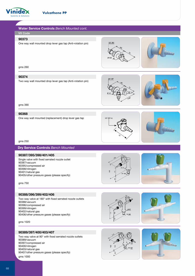
Vulcathene PP
68
90373One way wall mounted drop lever gas tap (Anti-rotation pin)
90374Two way wall mounted drop lever gas tap (Anti-rotation pin)
90368One way wall mounted (replacement) drop lever gas tap
90387/395/398/401/405Single valve with fixed serrated nozzle outlet90387/vacuum90395/compressed air90398/nitrogen90401/natural gas90405/other pressure gases (please specify)
90388/396/399/402/406Two way valve at 180° with fixed serrated nozzle outlets90388/vacuum90396/compressed air90399/nitrogen90402/natural gas90406/other pressure gases (please specify)
50
3/8" BSP (m)
Dry Service Controls Bench Mounted
gms 260
gms 390
gms 250
gms 750
gms 1020
VX Code
Water Service Controls Bench Mounted cont.
90389/397/400/403/407Two way valve at 90° with fixed serrated nozzle outlets90389/vacuum90397/compressed air90400/nitrogen90403/natural gas90407/other pressure gases (please specify)
gms 1000
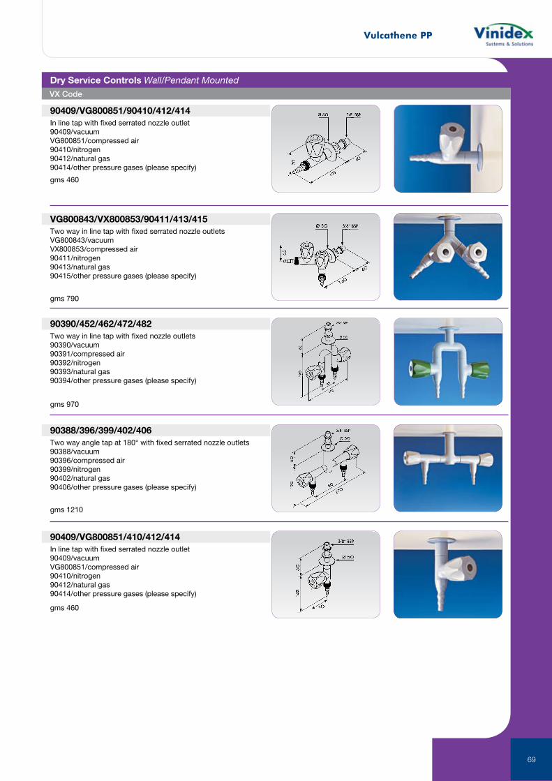
Vulcathene PP
69
VX Code
90409/VG800851/90410/412/414In line tap with fixed serrated nozzle outlet90409/vacuumVG800851/compressed air90410/nitrogen90412/natural gas90414/other pressure gases (please specify)
VG800843/VX800853/90411/413/415Two way in line tap with fixed serrated nozzle outletsVG800843/vacuumVX800853/compressed air90411/nitrogen90413/natural gas90415/other pressure gases (please specify)
90390/452/462/472/482Two way in line tap with fixed nozzle outlets90390/vacuum90391/compressed air90392/nitrogen90393/natural gas90394/other pressure gases (please specify)
90388/396/399/402/406Two way angle tap at 180° with fixed serrated nozzle outlets90388/vacuum90396/compressed air90399/nitrogen90402/natural gas90406/other pressure gases (please specify)
90409/VG800851/410/412/414In line tap with fixed serrated nozzle outlet90409/vacuumVG800851/compressed air90410/nitrogen90412/natural gas90414/other pressure gases (please specify)
Dry Service Controls Wall/Pendant Mounted
gms 460
gms 790
gms 970
gms 1210
gms 460
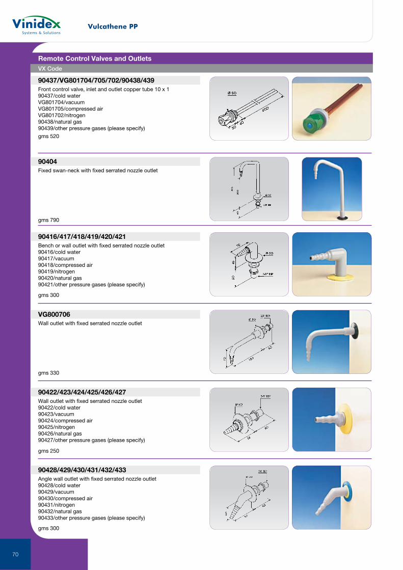
Vulcathene PP
70
VX Code
90437/VG801704/705/702/90438/439Front control valve, inlet and outlet copper tube 10 x 190437/cold waterVG801704/vacuumVG801705/compressed airVG801702/nitrogen90438/natural gas90439/other pressure gases (please specify)
90404Fixed swan-neck with fixed serrated nozzle outlet
90416/417/418/419/420/421Bench or wall outlet with fixed serrated nozzle outlet90416/cold water90417/vacuum90418/compressed air90419/nitrogen90420/natural gas90421/other pressure gases (please specify)
VG800706Wall outlet with fixed serrated nozzle outlet
90422/423/424/425/426/427Wall outlet with fixed serrated nozzle outlet90422/cold water90423/vacuum90424/compressed air90425/nitrogen90426/natural gas90427/other pressure gases (please specify)
90428/429/430/431/432/433Angle wall outlet with fixed serrated nozzle outlet90428/cold water90429/vacuum90430/compressed air90431/nitrogen90432/natural gas90433/other pressure gases (please specify)
Remote Control Valves and Outlets
gms 520
gms 790
gms 300
gms 330
gms 250
gms 300
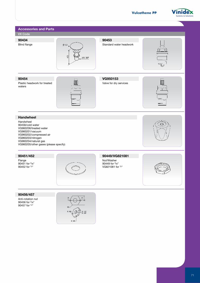
Vulcathene PP
71
90434Blind flange
90453Standard water headwork
90454Plastic headwork for treated waters
VG950153Valve for dry services
HandwheelHandwheel90458/cold waterVG960206/treated waterVG960201/vacuumVG960202/compressed airVG960203/nitrogenVG960204/natural gasVG960205/other gases (please specify)
90451/452Flange90451 for 3/8"90452 for ½"
90449/VG821081Nut/Washer90449 for 3/8"VG821081 for ½"
A A
42
R2
R. M5
R. M5
R. 1/2"R. 3/8"
90456/457Anti-rotation nut90456 for 3/8"90457 for ½"
Accessories and PartsVX Code
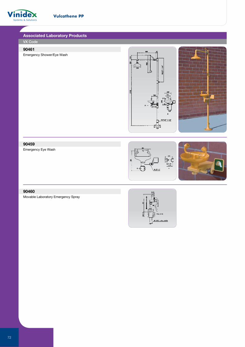
Vulcathene PP
72
90461Emergency Shower/Eye Wash
90459Emergency Eye Wash
90460Movable Laboratory Emergency Spray
Associated Laboratory ProductsVX Code

Vulcathene PP
73

Thermoplastic ValvesVinidex offers one of the most comprehensive ranges of high quality, high performance thermoplastic valves and actuation products available today. With more than 65 years of design and manufacturing experience, FIP lightweight, long life, maintenance free valves will save you time and money.
74
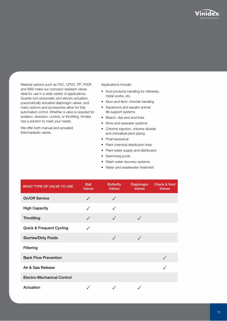
Material options such as PVC, CPVC, PP, PVDF, and ABS make our corrosion resistant valves ideal for use in a wide variety of applications. Quarter turn pneumatic and electric actuation, pneumatically actuated diaphragm valves, and many options and accessories allow for fully automated control. Whether a valve is required for isolation, diversion, control, or throttling, Vinidex has a solution to meet your needs.
We offer both manual and actuated thermoplastic valves.
Applications include:
• Acid products handling for refineries, metal works, etc.
• Alum and ferric chloride handling
• Aquariums and aquatic animal life support systems
• Bleach, dye and acid lines
• Brine and seawater systems
• Chlorine injection, chlorine dioxide and chloralkali plant piping
• Pharmaceutical
• Plant chemical distribution lines
• Plant water supply and distribution
• Swimming pools
• Wash water recovery systems
• Water and wastewater treatment
WHAT TYPE OF VALVE TO USEBall
ValvesButterfly Valves
Diaphragm Valves
Check & Vent Valves
On/Off Service 3 3
High Capacity 3 3
Throttling 3 3 3
Quick & Frequent Cycling 3
Slurries/Dirty Fluids 3 3
Filtering
Back Flow Prevention 3
Air & Gas Release 3
Electro-Mechanical Control
Actuation 3 3 3
75
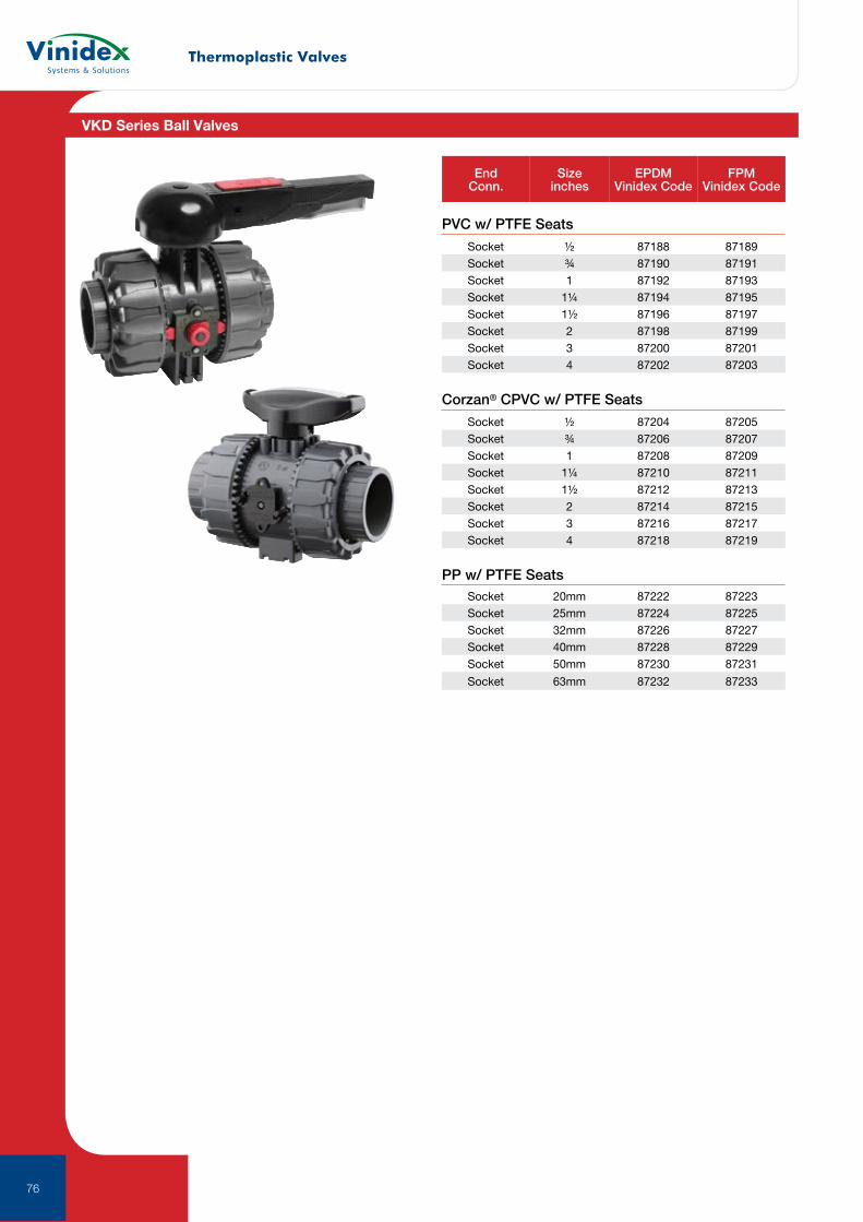
Thermoplastic Valves
76
PVC w/ PTFE Seats
EndConn.
Size inches
EPDMVinidex Code
FPMVinidex Code
Socket ½ 87188 87189Socket ¾ 87190 87191Socket 1 87192 87193Socket 1¼ 87194 87195Socket 1½ 87196 87197Socket 2 87198 87199Socket 3 87200 87201Socket 4 87202 87203
Corzan® CPVC w/ PTFE Seats
Socket ½ 87204 87205Socket ¾ 87206 87207Socket 1 87208 87209Socket 1¼ 87210 87211Socket 1½ 87212 87213Socket 2 87214 87215Socket 3 87216 87217Socket 4 87218 87219
PP w/ PTFE SeatsSocket 20mm 87222 87223Socket 25mm 87224 87225Socket 32mm 87226 87227Socket 40mm 87228 87229Socket 50mm 87230 87231
Socket 63mm 87232 87233
VKD Series Ball Valves
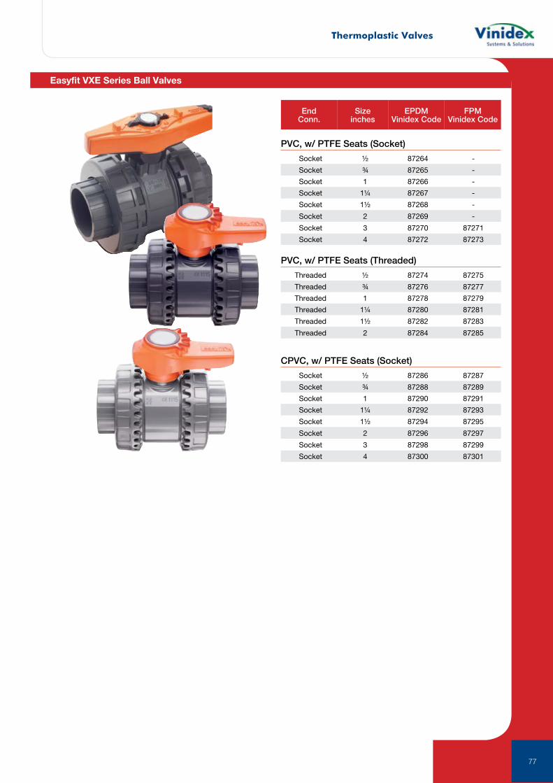
Thermoplastic Valves
77
EndConn.
Size inches
EPDMVinidex Code
FPMVinidex Code
PVC, w/ PTFE Seats (Socket)
CPVC, w/ PTFE Seats (Socket)
PVC, w/ PTFE Seats (Threaded)
Socket ½ 87264 -
Socket ¾ 87265 -
Socket 1 87266 -
Socket 1¼ 87267 -
Socket 1½ 87268 -
Socket 2 87269 -
Socket 3 87270 87271
Socket 4 87272 87273
Socket ½ 87286 87287
Socket ¾ 87288 87289
Socket 1 87290 87291
Socket 1¼ 87292 87293
Socket 1½ 87294 87295
Socket 2 87296 87297
Socket 3 87298 87299
Socket 4 87300 87301
Threaded ½ 87274 87275
Threaded ¾ 87276 87277
Threaded 1 87278 87279
Threaded 1¼ 87280 87281
Threaded 1½ 87282 87283
Threaded 2 87284 87285
Easyfit VXE Series Ball Valves
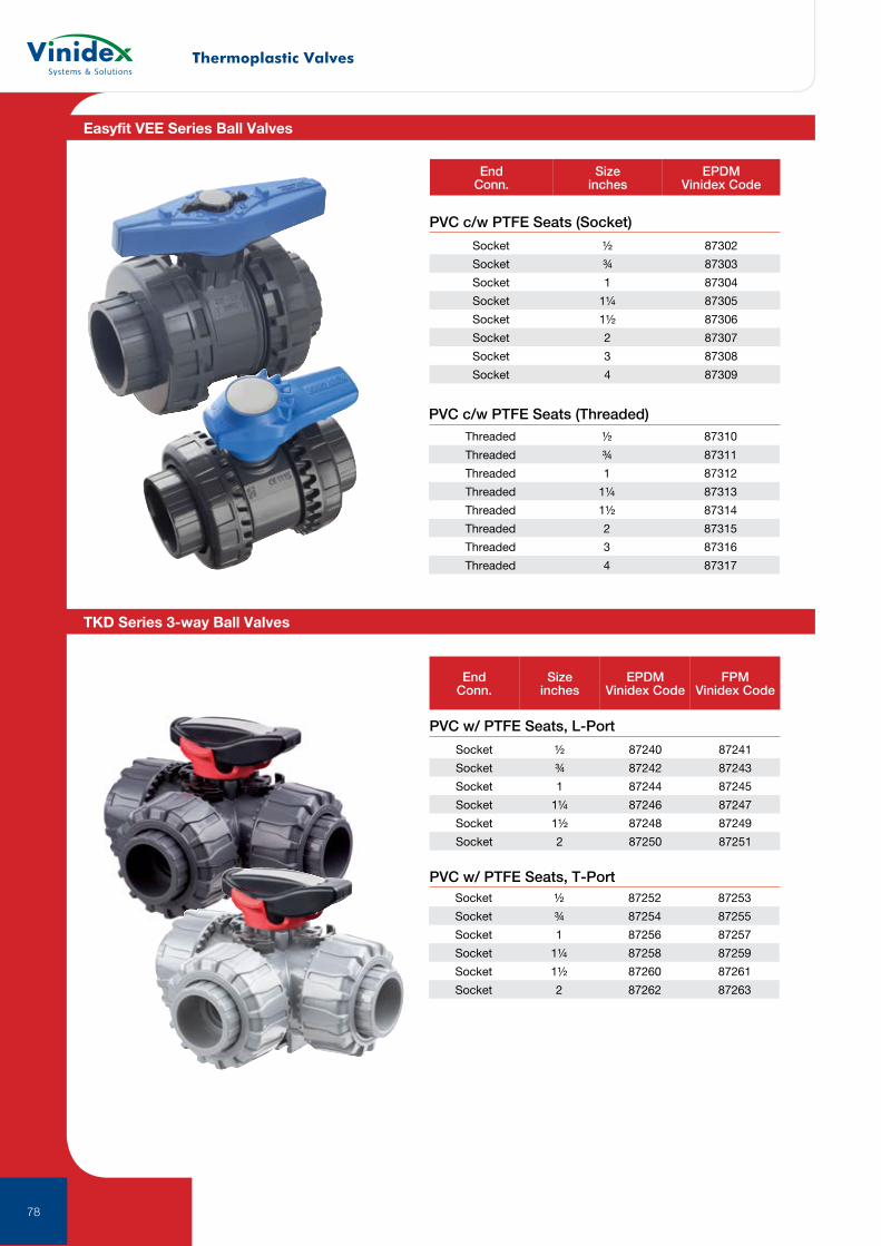
Thermoplastic Valves
78
EndConn.
Size inches
EPDMVinidex Code
Socket ½ 87302
Socket ¾ 87303
Socket 1 87304
Socket 1¼ 87305
Socket 1½ 87306
Socket 2 87307
Socket 3 87308
Socket 4 87309
Threaded ½ 87310
Threaded ¾ 87311
Threaded 1 87312
Threaded 1¼ 87313
Threaded 1½ 87314
Threaded 2 87315
Threaded 3 87316
Threaded 4 87317
PVC c/w PTFE Seats (Socket)
PVC c/w PTFE Seats (Threaded)
Easyfit VEE Series Ball Valves
TKD Series 3-way Ball Valves
Socket ½ 87240 87241
Socket ¾ 87242 87243
Socket 1 87244 87245
Socket 1¼ 87246 87247
Socket 1½ 87248 87249
Socket 2 87250 87251
Socket ½ 87252 87253
Socket ¾ 87254 87255
Socket 1 87256 87257
Socket 1¼ 87258 87259
Socket 1½ 87260 87261
Socket 2 87262 87263
PVC w/ PTFE Seats, L-Port
PVC w/ PTFE Seats, T-Port
EndConn.
Size inches
EPDMVinidex Code
FPMVinidex Code
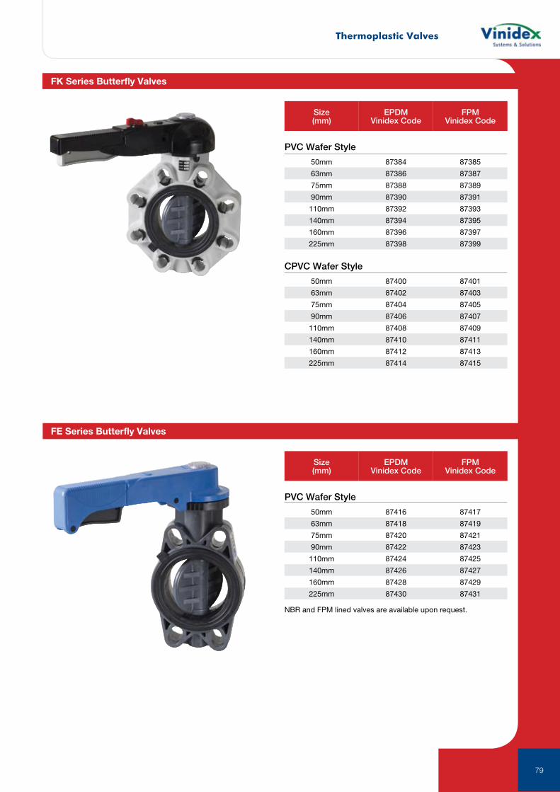
Thermoplastic Valves
79
PVC Wafer Style
CPVC Wafer Style
Size (mm)
EPDMVinidex Code
FPMVinidex Code
Size (mm)
EPDMVinidex Code
FPMVinidex Code
50mm 87384 87385
63mm 87386 87387
75mm 87388 87389
90mm 87390 87391
110mm 87392 87393
140mm 87394 87395
160mm 87396 87397
225mm 87398 87399
50mm 87416 87417
63mm 87418 87419
75mm 87420 87421
90mm 87422 87423
110mm 87424 87425
140mm 87426 87427
160mm 87428 87429
225mm 87430 87431
50mm 87400 87401
63mm 87402 87403
75mm 87404 87405
90mm 87406 87407
110mm 87408 87409
140mm 87410 87411
160mm 87412 87413
225mm 87414 87415
FK Series Butterfly Valves
PVC Wafer Style
NBR and FPM lined valves are available upon request.
FE Series Butterfly Valves
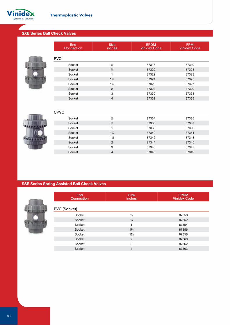
Thermoplastic Valves
80
PVC
EndConnection
Size inches
EPDMVinidex Code
FPM Vinidex Code
Socket ½ 87318 87319
Socket ¾ 87320 87321
Socket 1 87322 87323
Socket 1¼ 87324 87325
Socket 1½ 87326 87327
Socket 2 87328 87329
Socket 3 87330 87331
Socket 4 87332 87333
CPVC
Socket ½ 87334 87335
Socket ¾ 87336 87337
Socket 1 87338 87339
Socket 1¼ 87340 87341
Socket 1½ 87342 87343
Socket 2 87344 87345
Socket 3 87346 87347
Socket 4 87348 87349
PVC (Socket)
EndConnection
Size inches
EPDMVinidex Code
Socket ½ 87350
Socket ¾ 87352
Socket 1 87354
Socket 1¼ 87356
Socket 1½ 87358
Socket 2 87360
Socket 3 87362
Socket 4 87363
SXE Series Ball Check Valves
SSE Series Spring Assisted Ball Check Valves
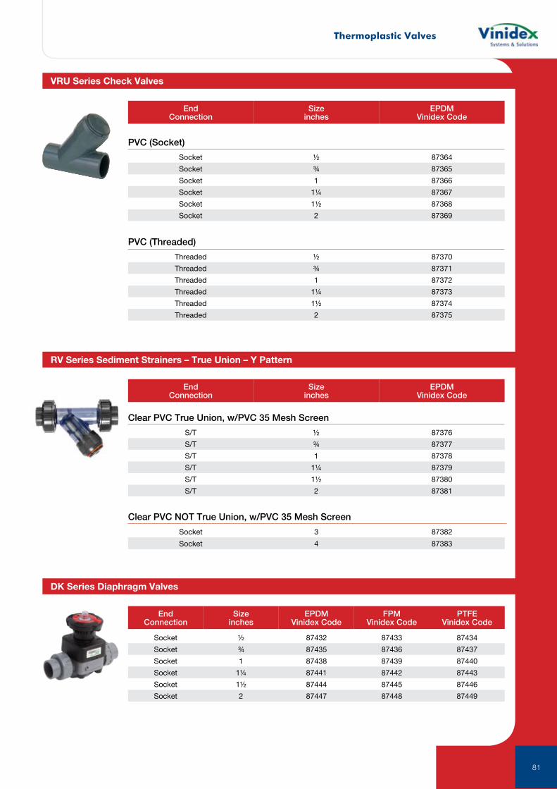
Thermoplastic Valves
81
EndConnection
Size inches
EPDMVinidex Code
FPM Vinidex Code
PTFE Vinidex Code
EndConnection
Size inches
EPDMVinidex Code
Socket ½ 87432 87433 87434
Socket ¾ 87435 87436 87437
Socket 1 87438 87439 87440
Socket 1¼ 87441 87442 87443
Socket 1½ 87444 87445 87446
Socket 2 87447 87448 87449
PVC (Socket)
PVC (Threaded)
EndConnection
Size inches
EPDMVinidex Code
Socket ½ 87364
Socket ¾ 87365
Socket 1 87366
Socket 1¼ 87367
Socket 1½ 87368
Socket 2 87369
Threaded ½ 87370
Threaded ¾ 87371
Threaded 1 87372
Threaded 1¼ 87373
Threaded 1½ 87374
Threaded 2 87375
VRU Series Check Valves
RV Series Sediment Strainers – True Union – Y Pattern
DK Series Diaphragm Valves
Clear PVC True Union, w/PVC 35 Mesh Screen
S/T ½ 87376
S/T ¾ 87377
S/T 1 87378
S/T 1¼ 87379
S/T 1½ 87380
S/T 2 87381
Clear PVC NOT True Union, w/PVC 35 Mesh Screen
Socket 3 87382
Socket 4 87383

UltragripPioneers in pipe solutions.
Next Generation UltraGrip is designed to offer a solution to joining plain-ended pipes and contains an end load resistant mechanism that grips and seals onto a variety of pipe materials including Cast Iron, Ductile Iron, Steel, PVC and PE.
82
The UltraGrip range is available in sizes DN40 – DN600. This gives you a single sealing and gripping product solution to cover the majority of pipes installed in an underground water network. The larger sized UltraGrip has been methodologically engineered to support a progressive gripping mechanism through an enhanced design, which has a larger footprint to increase the area of actuation at the point of contact. This results in an evenly distributed gripping function. It has also been designed to accommodate rough on-site handling through an intelligent carrier that maintains the gasket and grippers within the end ring, ensuring the fitting can be easily slid onto the pipe with no interference.
PE Solutions
Two solutions for connecting PE and rigid pipes are available. Choose from the UltraGrip range of couplings and adaptors or use the UltraGrip Pecat adaptor.
Repair Solutions
UltraGrip offers the ideal solution for repairing severely damaged, corroded or completely shattered pipes in difficult trench conditions.
Progressive Gripping
One of the key components of UltraGrip is the progressive gripping mechanism, which enhances its end-load restraint capabilities as the internal pressure in the pipe increases. A unique gripper system is suitable for all recommended pipe materials and combined with an engineered intelligent carrier which ensures maximum gripping strength around the full pipe circumference. This is achieved through uniform movement during installation and bolt-up.
In addition, the grippers are removable, allowing UltraGrip to be converted to a flexible product to allow for axial movement. The gripper and seal sub-assembly can accommodate diameter pipe outside variation up to 54mm, depending on nominal size.
Corrosion Protection
UltraGrip metal components are coated with Rilsan Nylon 11. Rilsan benefits include long term corrosion protection and resistance to impact damage. Additionally, the nuts and bolts are stainless steel coated with Dacromet/dry film lubricant, which prevents galling and provides long term corrosion protection.
Hygienic Protective Caps
Protection caps have been introduced to keep the fitting clean and free from any contamination. The caps are made of recyclable material to minimize the impact to the environment and ensure fittings rae clean and ready for use on potable water (DN600) or gas (DN400) applications.
83
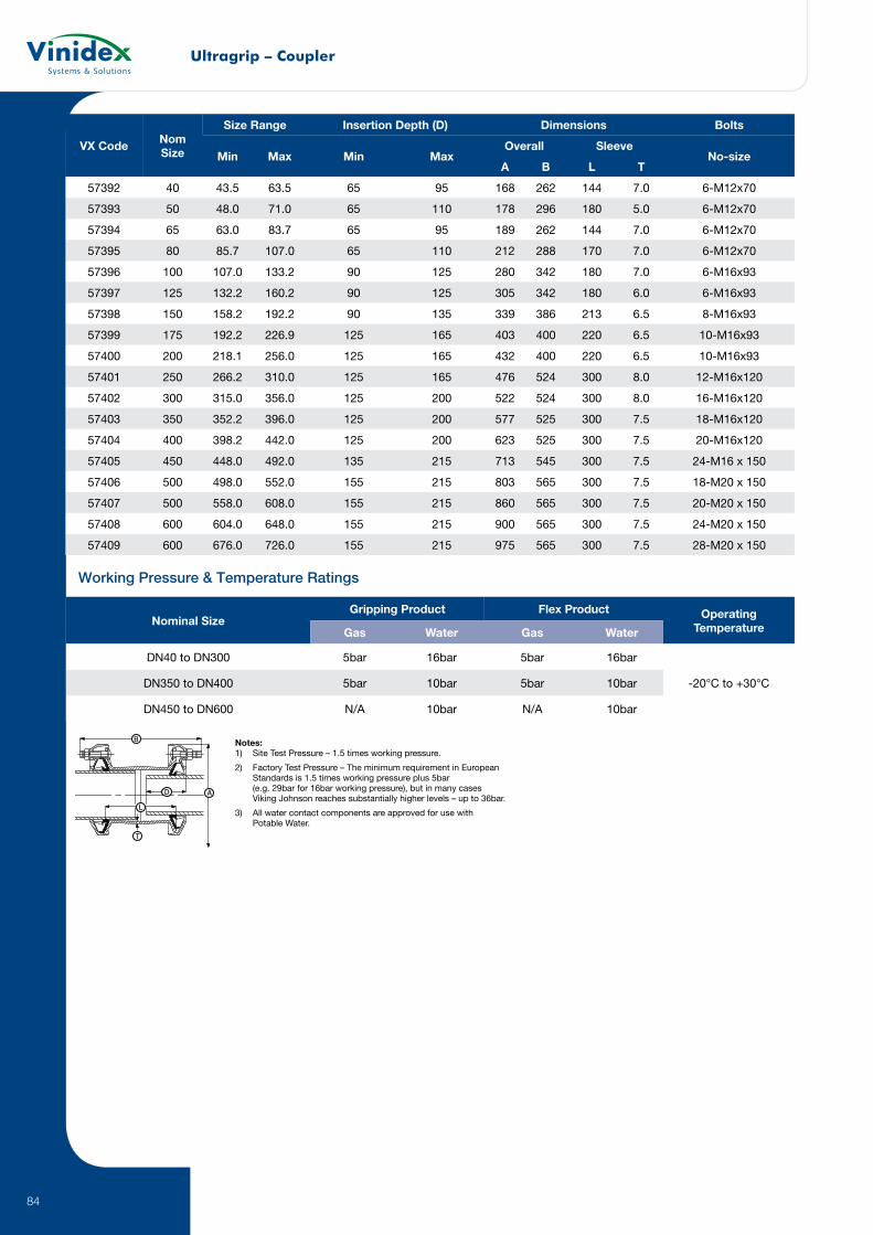
Ultragrip – Coupler
84
VX Code Nom Size
Size Range Insertion Depth (D) Dimensions Bolts
Min Max Min MaxOverall Sleeve
No-sizeA B L T
57392 40 43.5 63.5 65 95 168 262 144 7.0 6-M12x70
57393 50 48.0 71.0 65 110 178 296 180 5.0 6-M12x70
57394 65 63.0 83.7 65 95 189 262 144 7.0 6-M12x70
57395 80 85.7 107.0 65 110 212 288 170 7.0 6-M12x70
57396 100 107.0 133.2 90 125 280 342 180 7.0 6-M16x93
57397 125 132.2 160.2 90 125 305 342 180 6.0 6-M16x93
57398 150 158.2 192.2 90 135 339 386 213 6.5 8-M16x93
57399 175 192.2 226.9 125 165 403 400 220 6.5 10-M16x93
57400 200 218.1 256.0 125 165 432 400 220 6.5 10-M16x93
57401 250 266.2 310.0 125 165 476 524 300 8.0 12-M16x120
57402 300 315.0 356.0 125 200 522 524 300 8.0 16-M16x120
57403 350 352.2 396.0 125 200 577 525 300 7.5 18-M16x120
57404 400 398.2 442.0 125 200 623 525 300 7.5 20-M16x120
57405 450 448.0 492.0 135 215 713 545 300 7.5 24-M16 x 150
57406 500 498.0 552.0 155 215 803 565 300 7.5 18-M20 x 150
57407 500 558.0 608.0 155 215 860 565 300 7.5 20-M20 x 150
57408 600 604.0 648.0 155 215 900 565 300 7.5 24-M20 x 150
57409 600 676.0 726.0 155 215 975 565 300 7.5 28-M20 x 150
Working Pressure & Temperature Ratings
Nominal SizeGripping Product Flex Product Operating
TemperatureGas Water Gas Water
DN40 to DN300 5bar 16bar 5bar 16bar
-20°C to +30°CDN350 to DN400 5bar 10bar 5bar 10bar
DN450 to DN600 N/A 10bar N/A 10bar
B
L
A
T
D
Notes: 1) Site Test Pressure – 1.5 times working pressure.
2) Factory Test Pressure – The minimum requirement in European Standards is 1.5 times working pressure plus 5bar (e.g. 29bar for 16bar working pressure), but in many cases Viking Johnson reaches substantially higher levels – up to 36bar.
3) All water contact components are approved for use with Potable Water.
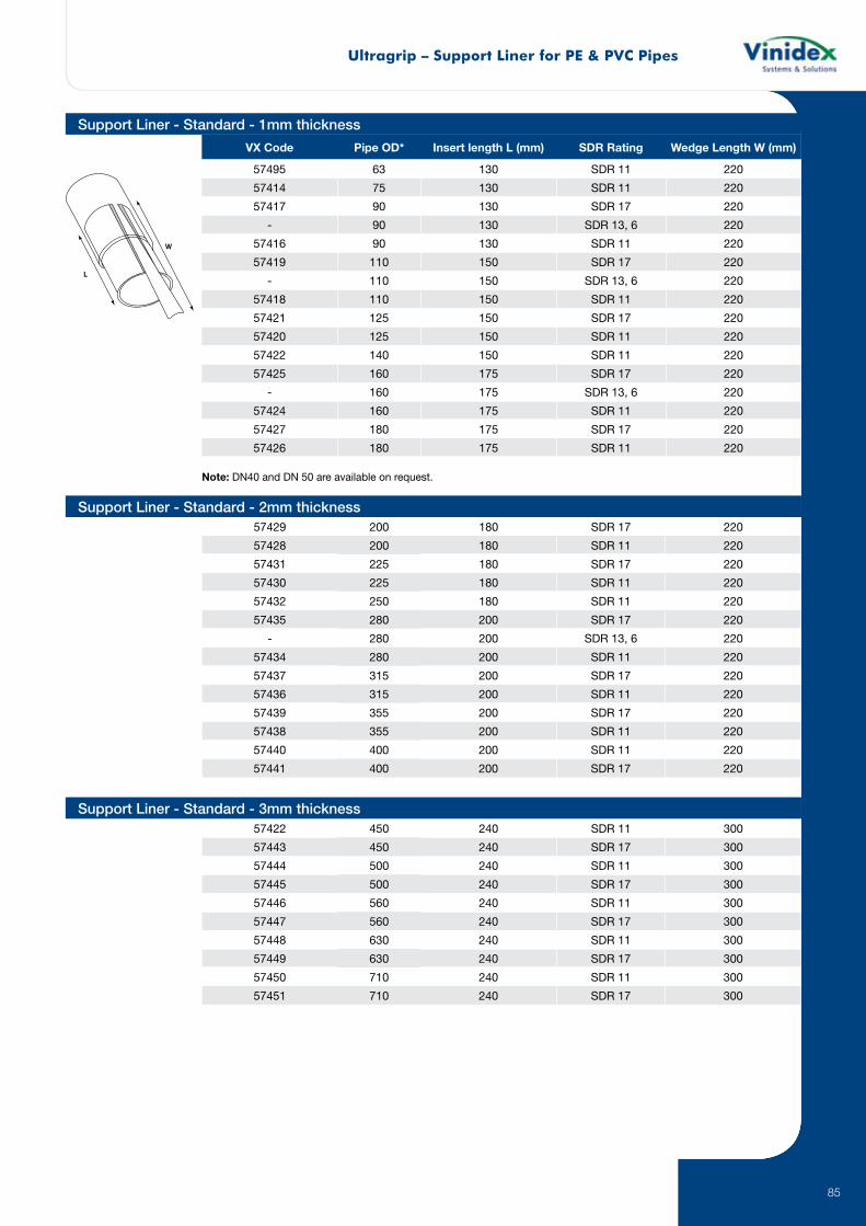
Ultragrip – Support Liner for PE & PVC Pipes
85
VX Code Pipe OD* Insert length L (mm) SDR Rating Wedge Length W (mm)
57495 63 130 SDR 11 220
57414 75 130 SDR 11 220
57417 90 130 SDR 17 220
- 90 130 SDR 13, 6 220
57416 90 130 SDR 11 220
57419 110 150 SDR 17 220
- 110 150 SDR 13, 6 220
57418 110 150 SDR 11 220
57421 125 150 SDR 17 220
57420 125 150 SDR 11 220
57422 140 150 SDR 11 220
57425 160 175 SDR 17 220
- 160 175 SDR 13, 6 220
57424 160 175 SDR 11 220
57427 180 175 SDR 17 220
57426 180 175 SDR 11 220
57422 450 240 SDR 11 300
57443 450 240 SDR 17 300
57444 500 240 SDR 11 300
57445 500 240 SDR 17 300
57446 560 240 SDR 11 300
57447 560 240 SDR 17 300
57448 630 240 SDR 11 300
57449 630 240 SDR 17 300
57450 710 240 SDR 11 300
57451 710 240 SDR 17 300
Note: DN40 and DN 50 are available on request.
57429 200 180 SDR 17 220
57428 200 180 SDR 11 220
57431 225 180 SDR 17 220
57430 225 180 SDR 11 220
57432 250 180 SDR 11 220
57435 280 200 SDR 17 220
- 280 200 SDR 13, 6 220
57434 280 200 SDR 11 220
57437 315 200 SDR 17 220
57436 315 200 SDR 11 220
57439 355 200 SDR 17 220
57438 355 200 SDR 11 220
57440 400 200 SDR 11 220
57441 400 200 SDR 17 220
Support Liner - Standard - 1mm thickness
Support Liner - Standard - 2mm thickness
Support Liner - Standard - 3mm thickness

StraubThe name STRAUB is synonymous with expertise, quality and reliability. As an internationally renowned manufacturer of pipe joints, STRAUB not only invented ”the original”, it also owns the patents on several outstanding features that still make the famous STRAUB pipe coupling the unquestioned leader in its class. Our unique pipe coupling concept is backed by 40 years of experience and continuous development, guaranteeing Swiss quality and value.
86
Our total product and customer focus enables us to respond quickly and efficiently to our customers’ most stringent requirements. There is no substitute for our experience. STRAUB invented the “original” and continues to refine and improve the design today. Pipe couplings are our only business – we are passionate about what we do.
We obtained the ISO 9001 Quality Assurance Certificate in 1995 and ISO 14001 in 2008. This confirms proven STRAUB quality and made us once again world pioneers in the area of progressive sealing pipe joints.
One unique technical principle: two basic types, but with innumerable applications, wherever pipes have to be joined together - that is the secret of STRAUB pipe joints. Based on the well-proven coupling technology, we combine different pipe materials for optimum solutions for customers.
Their safety and reliability have been examined and certificated by public authorities, insurance companies, technical inspectorates and licensing institutions for all the major industrial sectors in most industrial countries. You can rely on STRAUB couplings.
The progressive sealing effect
As the pressure in the pipe increases, so does the force on the sealing lips, due to the flow through the pressure equalisation channel.
The progressive anchoring effect
As the axial loading on the pipe increases due to increased internal pressure or external influences, the teeth bite even deeper into the pipe to compensate. The penetration depth of the anchoring ring teeth under pressure is 0.1 – 0.3 mm.
STRAUB-METAL-GRIP is a high-performance coupling suitable for all pipe systems. This coupling is mainly used for building construction or civil engineering, power plants and demanding shipbuilding / offshore applications or as a machinery component.
STRAUB-METAL-GRIP also absorbs unexpected field stress and applies perfect for seismic retrofits.
87

Straub
88
Remarks:Follow fitting / disassembly instructionsPS = Working pressure considering the application loadsMaterial Grade W4 304 Stainless SteelTest pressure = PS x 1.5 (for example industry, water supply etc.)The pressure values are valid on radial rigid carbon steel pipes under static loadsRefer to the technical manual for minimum wall thickness of pipeStrip inserts are supplied with all couplings sold in Australia
VX Code NBR
VX Code NBR
Pipe OD (mm)
Clamping Range (mm)
PS (bar)
B (mm)
C (mm)
DV (mm)
KV (mm)
Pipe Gap with Strip Insert (mm)
Torque rate (Nm)
Allen head (mm)
75970 75993 30.0 29.5 - 30.5 67.0 46/67 18 47 70 5 10 875971 75994 33.7 33.2 - 34.2 62.0 46/67 18 52 75 5 10 875972 75995 38.0 37.5 - 38.5 58.0 61.0 19 58 90 5-10 15 875973 75996 42.4 41.9 - 42.9 53.0 61 20 62 90 5-10 15 875974 75997 44.5 44.0 - 45.0 48.0 61 20 64 95 5-10 15 875975 75998 48.3 47.8 - 48.8 44.0 61 20 68 95 5-10 15 875976 75999 54.0 53.5 - 54.5 39.0 77 38 74 100 5-15 20 875977 76000 57.0 56.4 - 57.6 37.0 77 32 77 105 5-25 20 875978 76001 60.3 59.7 - 60.9 37.0 77 32 82 110 5-25 20 875979 76002 63.5 62.9 - 64.1 37.0 77 32 84 114 5-25 35 875980 76003 76.1 75.3 - 76.9 56.0 94 39 100 130 5-25 35 1075981 76004 84.0 83.2 - 84.8 45.0 94 39 112 140 5-25 35 1075982 76005 88.9 88.0 - 89.8 41.0 94 39 117 145 5-25 35 1075983 76006 104.0 103.0 - 105.0 37.0 94 39 133 160 5-25 35 1075984 76007 108.0 106.9 - 109.1 35.0 94 39 133 160 5-25 35 1075985 76008 114.3 113.2 - 115.4 34.0 94 39 139 165 5-25 35 1075986 76009 129.0 127.7 - 130.3 33.0 108 43 160 190 5-25 60 1275987 76010 133.0 131.7 - 134.3 33.0 108 43 160 190 5-25 60 1275988 76011 139.7 138.3 - 141.1 32.0 109 43 168 200 5-25 60 1275989 154.0 152.5 - 155.5 32.0 109 51 186 215 5-25 60 1275990 76012 159.0 157.4 - 160.6 31.0 109 43 187 215 5-25 60 1275991 76013 168.3 166.6 - 170.0 29.0 109 43 200 230 5-25 60 1275992 76014 219.1 216.9 - 221.3 26.0 150 60 259 295 5-35 100 16
Available upon request
STRAUB-METAL-GRIP Ø 30.0 - 219.1 mm
Sealing Sleeve Temp: -30º C up to +100º C
EPDM Medium: all qualities of water, waste water, air, solids and chemical products
Sealing Sleeve Temp: -20º C up to +80º C
NBR Medium: water, gas, oil, fuel and other hydrocarbons
Sealing Sleeve Temp: -20º C up to +125º C
H-NBR (on request) Medium: water, gas, oil and fuel and other hydrocarbons
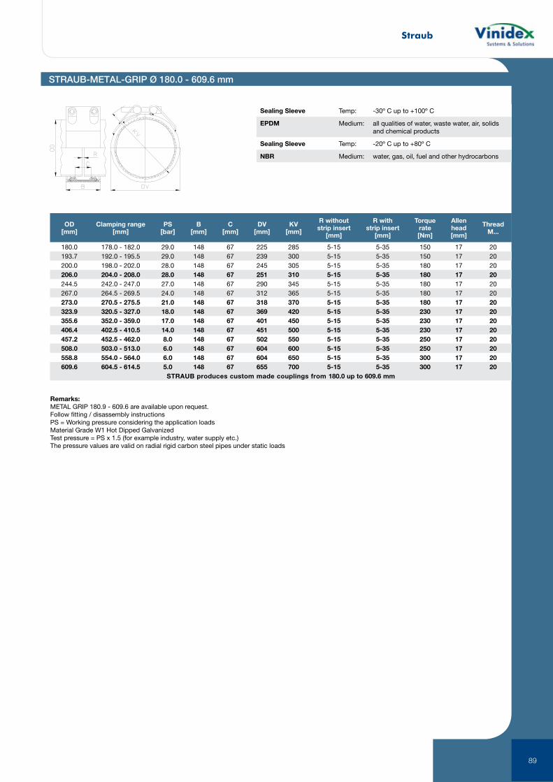
Straub
89
Remarks:METAL GRIP 180.9 - 609.6 are available upon request.Follow fitting / disassembly instructionsPS = Working pressure considering the application loadsMaterial Grade W1 Hot Dipped GalvanizedTest pressure = PS x 1.5 (for example industry, water supply etc.)The pressure values are valid on radial rigid carbon steel pipes under static loads
OD[mm]
Clamping range[mm]
PS[bar]
B[mm]
C[mm]
DV[mm]
KV[mm]
R withoutstrip insert
[mm]
R withstrip insert
[mm]
Torquerate[Nm]
Allenhead[mm]
ThreadM...
180.0 178.0 - 182.0 29.0 148 67 225 285 5-15 5-35 150 17 20193.7 192.0 - 195.5 29.0 148 67 239 300 5-15 5-35 150 17 20200.0 198.0 - 202.0 28.0 148 67 245 305 5-15 5-35 180 17 20206.0 204.0 - 208.0 28.0 148 67 251 310 5-15 5-35 180 17 20244.5 242.0 - 247.0 27.0 148 67 290 345 5-15 5-35 180 17 20267.0 264.5 - 269.5 24.0 148 67 312 365 5-15 5-35 180 17 20273.0 270.5 - 275.5 21.0 148 67 318 370 5-15 5-35 180 17 20323.9 320.5 - 327.0 18.0 148 67 369 420 5-15 5-35 230 17 20355.6 352.0 - 359.0 17.0 148 67 401 450 5-15 5-35 230 17 20406.4 402.5 - 410.5 14.0 148 67 451 500 5-15 5-35 230 17 20457.2 452.5 - 462.0 8.0 148 67 502 550 5-15 5-35 250 17 20508.0 503.0 - 513.0 6.0 148 67 604 600 5-15 5-35 250 17 20558.8 554.0 - 564.0 6.0 148 67 604 650 5-15 5-35 300 17 20609.6 604.5 - 614.5 5.0 148 67 655 700 5-15 5-35 300 17 20
STRAUB produces custom made couplings from 180.0 up to 609.6 mm
STRAUB-METAL-GRIP Ø 180.0 - 609.6 mm
Sealing Sleeve Temp: -30º C up to +100º C
EPDM Medium: all qualities of water, waste water, air, solids and chemical products
Sealing Sleeve Temp: -20º C up to +80º C
NBR Medium: water, gas, oil, fuel and other hydrocarbons
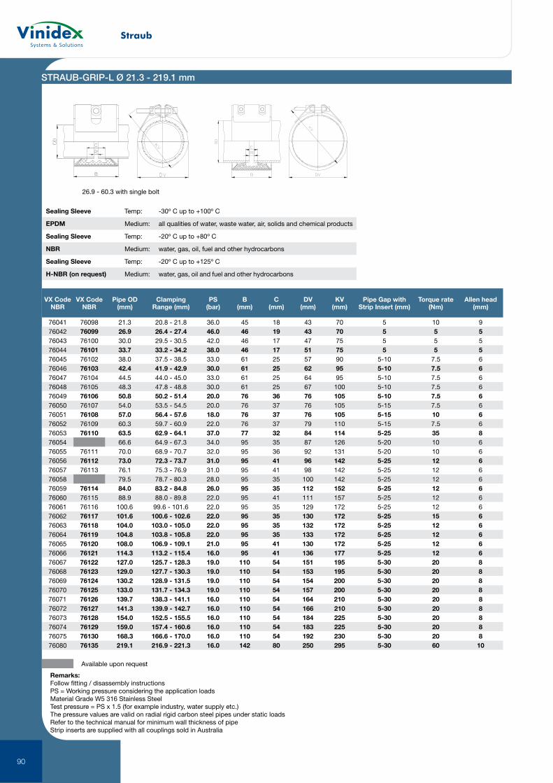
Straub
90
STRAUB-GRIP-L Ø 21.3 - 219.1 mm
VX Code NBR
VX Code NBR
Pipe OD (mm)
Clamping Range (mm)
PS (bar)
B (mm)
C (mm)
DV (mm)
KV (mm)
Pipe Gap with Strip Insert (mm)
Torque rate (Nm)
Allen head (mm)
76041 76098 21.3 20.8 - 21.8 36.0 45 18 43 70 5 10 976042 76099 26.9 26.4 - 27.4 46.0 46 19 43 70 5 5 576043 76100 30.0 29.5 - 30.5 42.0 46 17 47 75 5 5 576044 76101 33.7 33.2 - 34.2 38.0 46 17 51 75 5 5 576045 76102 38.0 37.5 - 38.5 33.0 61 25 57 90 5-10 7.5 676046 76103 42.4 41.9 - 42.9 30.0 61 25 62 95 5-10 7.5 676047 76104 44.5 44.0 - 45.0 33.0 61 25 64 95 5-10 7.5 676048 76105 48.3 47.8 - 48.8 30.0 61 25 67 100 5-10 7.5 676049 76106 50.8 50.2 - 51.4 20.0 76 36 76 105 5-10 7.5 676050 76107 54.0 53.5 - 54.5 20.0 76 37 76 105 5-15 7.5 676051 76108 57.0 56.4 - 57.6 18.0 76 37 76 105 5-15 10 676052 76109 60.3 59.7 - 60.9 22.0 76 37 79 110 5-15 7.5 676053 76110 63.5 62.9 - 64.1 37.0 77 32 84 114 5-25 35 876054 66.6 64.9 - 67.3 34.0 95 35 87 126 5-20 10 676055 76111 70.0 68.9 - 70.7 32.0 95 36 92 131 5-20 10 676056 76112 73.0 72.3 - 73.7 31.0 95 41 96 142 5-25 12 676057 76113 76.1 75.3 - 76.9 31.0 95 41 98 142 5-25 12 676058 79.5 78.7 - 80.3 28.0 95 35 100 142 5-25 12 676059 76114 84.0 83.2 - 84.8 26.0 95 35 112 152 5-25 12 676060 76115 88.9 88.0 - 89.8 22.0 95 41 111 157 5-25 12 676061 76116 100.6 99.6 - 101.6 22.0 95 35 129 172 5-25 12 676062 76117 101.6 100.6 - 102.6 22.0 95 35 130 172 5-25 15 676063 76118 104.0 103.0 - 105.0 22.0 95 35 132 172 5-25 12 676064 76119 104.8 103.8 - 105.8 22.0 95 35 133 172 5-25 12 676065 76120 108.0 106.9 - 109.1 21.0 95 41 130 172 5-25 12 676066 76121 114.3 113.2 - 115.4 16.0 95 41 136 177 5-25 12 676067 76122 127.0 125.7 - 128.3 19.0 110 54 151 195 5-30 20 876068 76123 129.0 127.7 - 130.3 19.0 110 54 153 195 5-30 20 876069 76124 130.2 128.9 - 131.5 19.0 110 54 154 200 5-30 20 876070 76125 133.0 131.7 - 134.3 19.0 110 54 157 200 5-30 20 876071 76126 139.7 138.3 - 141.1 16.0 110 54 164 210 5-30 20 876072 76127 141.3 139.9 - 142.7 16.0 110 54 166 210 5-30 20 876073 76128 154.0 152.5 - 155.5 16.0 110 54 184 225 5-30 20 876074 76129 159.0 157.4 - 160.6 16.0 110 54 183 225 5-30 20 876075 76130 168.3 166.6 - 170.0 16.0 110 54 192 230 5-30 20 876080 76135 219.1 216.9 - 221.3 16.0 142 80 250 295 5-30 60 10
Available upon request
26.9 - 60.3 with single bolt
Sealing Sleeve Temp: -30º C up to +100º C
EPDM Medium: all qualities of water, waste water, air, solids and chemical products
Sealing Sleeve Temp: -20º C up to +80º C
NBR Medium: water, gas, oil, fuel and other hydrocarbons
Sealing Sleeve Temp: -20º C up to +125º C
H-NBR (on request) Medium: water, gas, oil and fuel and other hydrocarbons
Remarks:Follow fitting / disassembly instructionsPS = Working pressure considering the application loadsMaterial Grade W5 316 Stainless SteelTest pressure = PS x 1.5 (for example industry, water supply etc.)The pressure values are valid on radial rigid carbon steel pipes under static loadsRefer to the technical manual for minimum wall thickness of pipeStrip inserts are supplied with all couplings sold in Australia
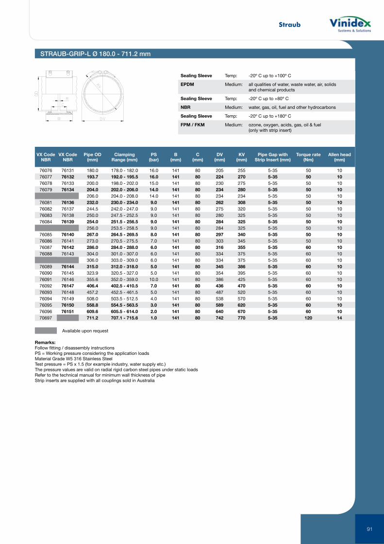
Straub
91
STRAUB-GRIP-L Ø 180.0 - 711.2 mm
VX Code NBR
VX Code NBR
Pipe OD (mm)
Clamping Range (mm)
PS (bar)
B (mm)
C (mm)
DV (mm)
KV (mm)
Pipe Gap with Strip Insert (mm)
Torque rate (Nm)
Allen head (mm)
76076 76131 180.0 178.0 - 182.0 16.0 141 80 205 255 5-35 50 1076077 76132 193.7 192.0 - 195.5 16.0 141 80 224 270 5-35 50 1076078 76133 200.0 198.0 - 202.0 15.0 141 80 230 275 5-35 50 1076079 76134 204.0 202.0 - 206.0 14.0 141 80 234 280 5-35 50 10
206.0 204.0 - 208.0 14.0 141 80 234 234 5-35 50 1076081 76136 232.0 230.0 - 234.0 9.0 141 80 262 308 5-35 50 1076082 76137 244.5 242.0 - 247.0 9.0 141 80 275 320 5-35 50 1076083 76138 250.0 247.5 - 252.5 9.0 141 80 280 325 5-35 50 1076084 76139 254.0 251.5 - 256.5 9.0 141 80 284 325 5-35 50 10
256.0 253.5 - 258.5 9.0 141 80 284 325 5-35 50 1076085 76140 267.0 264.5 - 269.5 8.0 141 80 297 340 5-35 50 1076086 76141 273.0 270.5 - 275.5 7.0 141 80 303 345 5-35 50 1076087 76142 286.0 284.0 - 288.0 6.0 141 80 316 355 5-35 60 1076088 76143 304.0 301.0 - 307.0 6.0 141 80 334 375 5-35 60 10
306.0 303.0 - 309.0 6.0 141 80 334 375 5-35 60 1076089 76144 315.0 312.0 - 318.0 5.0 141 80 345 386 5-35 60 1076090 76145 323.9 320.5 - 327.0 5.0 141 80 354 395 5-35 60 1076091 76146 355.6 352.0 - 359.0 10.0 141 80 386 425 5-35 60 1076092 76147 406.4 402.5 - 410.5 7.0 141 80 436 470 5-35 60 1076093 76148 457.2 452.5 - 461.5 5.0 141 80 487 520 5-35 60 1076094 76149 508.0 503.5 - 512.5 4.0 141 80 538 570 5-35 60 1076095 76150 558.8 554.5 - 563.5 3.0 141 80 589 620 5-35 60 1076096 76151 609.6 605.5 - 614.0 2.0 141 80 640 670 5-35 60 1070697 711.2 707.1 - 715.6 1.0 141 80 742 770 5-35 120 14
Available upon request
Sealing Sleeve Temp: -20º C up to +100º C
EPDM Medium: all qualities of water, waste water, air, solids and chemical products
Sealing Sleeve Temp: -20º C up to +80º C
NBR Medium: water, gas, oil, fuel and other hydrocarbons
Sealing Sleeve Temp: -20º C up to +180º C
FPM / FKM Medium: ozone, oxygen, acids, gas, oil & fuel (only with strip insert)
Remarks:Follow fitting / disassembly instructionsPS = Working pressure considering the application loadsMaterial Grade W5 316 Stainless SteelTest pressure = PS x 1.5 (for example industry, water supply etc.)The pressure values are valid on radial rigid carbon steel pipes under static loadsRefer to the technical manual for minimum wall thickness of pipeStrip inserts are supplied with all couplings sold in Australia
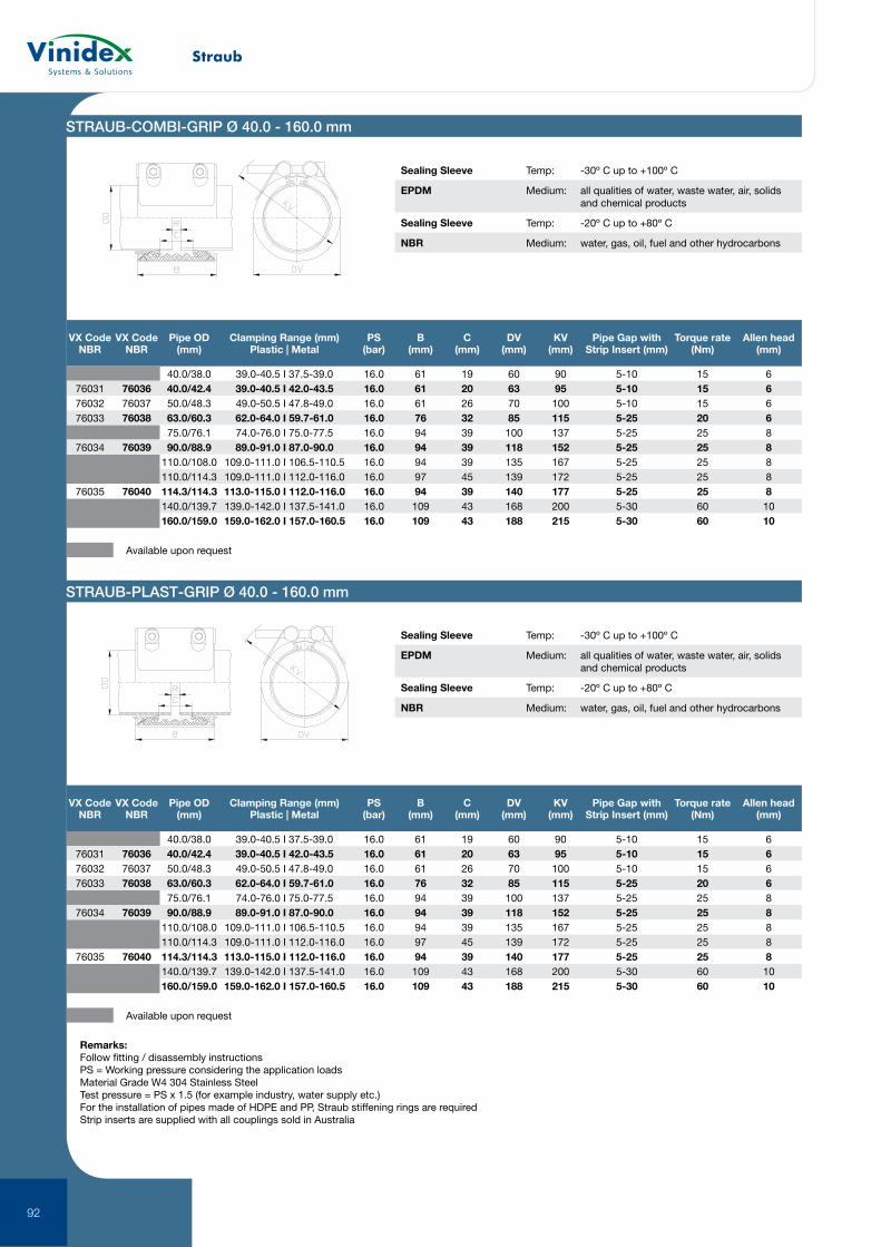
Straub
92
STRAUB-COMBI-GRIP Ø 40.0 - 160.0 mm
STRAUB-PLAST-GRIP Ø 40.0 - 160.0 mm
VX Code NBR
VX Code NBR
Pipe OD (mm)
Clamping Range (mm) Plastic | Metal
PS (bar)
B (mm)
C (mm)
DV (mm)
KV (mm)
Pipe Gap with Strip Insert (mm)
Torque rate (Nm)
Allen head (mm)
40.0/38.0 39.0-40.5 I 37.5-39.0 16.0 61 19 60 90 5-10 15 676031 76036 40.0/42.4 39.0-40.5 I 42.0-43.5 16.0 61 20 63 95 5-10 15 676032 76037 50.0/48.3 49.0-50.5 I 47.8-49.0 16.0 61 26 70 100 5-10 15 676033 76038 63.0/60.3 62.0-64.0 I 59.7-61.0 16.0 76 32 85 115 5-25 20 6
75.0/76.1 74.0-76.0 I 75.0-77.5 16.0 94 39 100 137 5-25 25 876034 76039 90.0/88.9 89.0-91.0 I 87.0-90.0 16.0 94 39 118 152 5-25 25 8
110.0/108.0 109.0-111.0 I 106.5-110.5 16.0 94 39 135 167 5-25 25 8110.0/114.3 109.0-111.0 I 112.0-116.0 16.0 97 45 139 172 5-25 25 8
76035 76040 114.3/114.3 113.0-115.0 I 112.0-116.0 16.0 94 39 140 177 5-25 25 8140.0/139.7 139.0-142.0 I 137.5-141.0 16.0 109 43 168 200 5-30 60 10160.0/159.0 159.0-162.0 I 157.0-160.5 16.0 109 43 188 215 5-30 60 10
Available upon request
VX Code NBR
VX Code NBR
Pipe OD (mm)
Clamping Range (mm) Plastic | Metal
PS (bar)
B (mm)
C (mm)
DV (mm)
KV (mm)
Pipe Gap with Strip Insert (mm)
Torque rate (Nm)
Allen head (mm)
40.0/38.0 39.0-40.5 I 37.5-39.0 16.0 61 19 60 90 5-10 15 676031 76036 40.0/42.4 39.0-40.5 I 42.0-43.5 16.0 61 20 63 95 5-10 15 676032 76037 50.0/48.3 49.0-50.5 I 47.8-49.0 16.0 61 26 70 100 5-10 15 676033 76038 63.0/60.3 62.0-64.0 I 59.7-61.0 16.0 76 32 85 115 5-25 20 6
75.0/76.1 74.0-76.0 I 75.0-77.5 16.0 94 39 100 137 5-25 25 876034 76039 90.0/88.9 89.0-91.0 I 87.0-90.0 16.0 94 39 118 152 5-25 25 8
110.0/108.0 109.0-111.0 I 106.5-110.5 16.0 94 39 135 167 5-25 25 8110.0/114.3 109.0-111.0 I 112.0-116.0 16.0 97 45 139 172 5-25 25 8
76035 76040 114.3/114.3 113.0-115.0 I 112.0-116.0 16.0 94 39 140 177 5-25 25 8140.0/139.7 139.0-142.0 I 137.5-141.0 16.0 109 43 168 200 5-30 60 10160.0/159.0 159.0-162.0 I 157.0-160.5 16.0 109 43 188 215 5-30 60 10
Available upon request
Sealing Sleeve Temp: -30º C up to +100º C
EPDM Medium: all qualities of water, waste water, air, solids and chemical products
Sealing Sleeve Temp: -20º C up to +80º C
NBR Medium: water, gas, oil, fuel and other hydrocarbons
Sealing Sleeve Temp: -30º C up to +100º C
EPDM Medium: all qualities of water, waste water, air, solids and chemical products
Sealing Sleeve Temp: -20º C up to +80º C
NBR Medium: water, gas, oil, fuel and other hydrocarbons
Remarks:Follow fitting / disassembly instructionsPS = Working pressure considering the application loadsMaterial Grade W4 304 Stainless SteelTest pressure = PS x 1.5 (for example industry, water supply etc.)For the installation of pipes made of HDPE and PP, Straub stiffening rings are requiredStrip inserts are supplied with all couplings sold in Australia
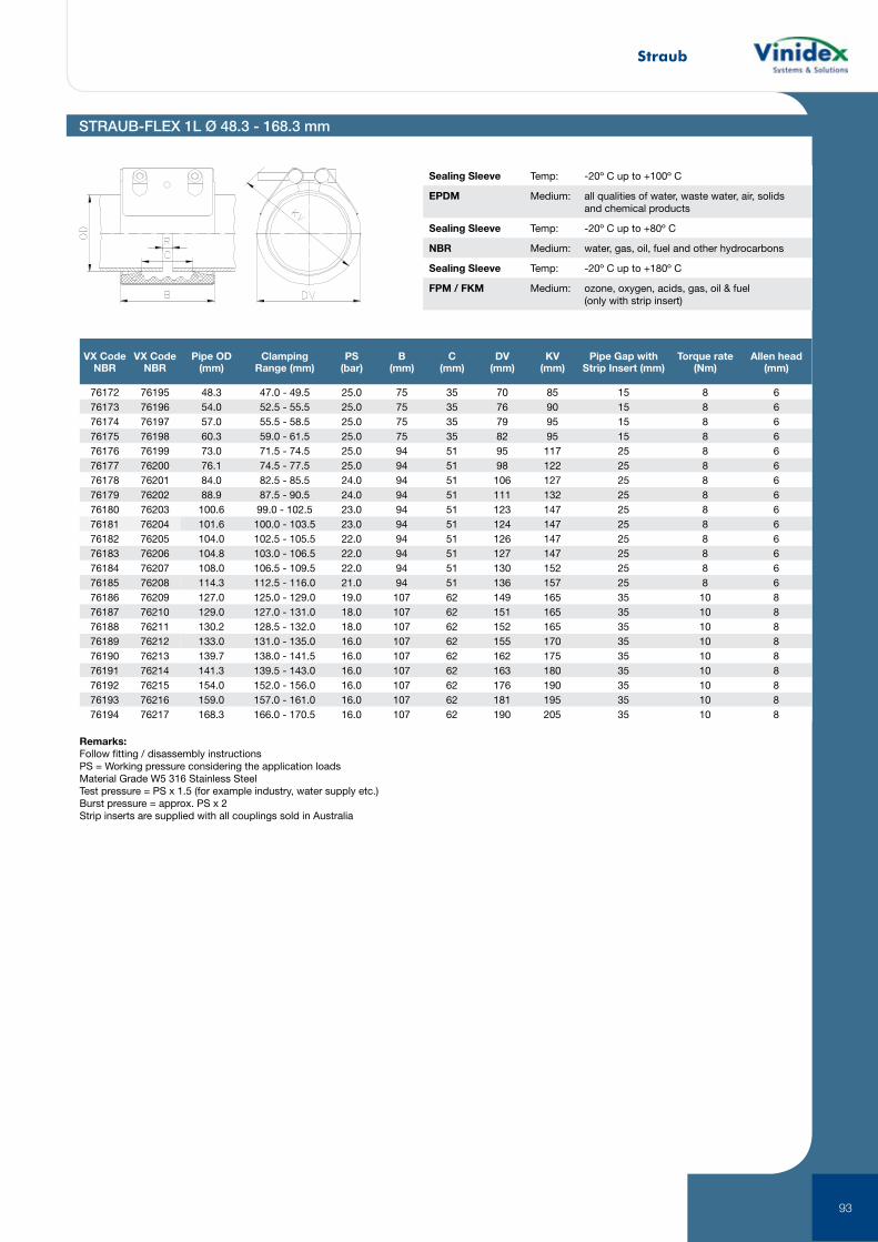
Straub
93
VX Code NBR
VX Code NBR
Pipe OD (mm)
Clamping Range (mm)
PS (bar)
B (mm)
C (mm)
DV (mm)
KV (mm)
Pipe Gap with Strip Insert (mm)
Torque rate (Nm)
Allen head (mm)
76172 76195 48.3 47.0 - 49.5 25.0 75 35 70 85 15 8 676173 76196 54.0 52.5 - 55.5 25.0 75 35 76 90 15 8 676174 76197 57.0 55.5 - 58.5 25.0 75 35 79 95 15 8 676175 76198 60.3 59.0 - 61.5 25.0 75 35 82 95 15 8 676176 76199 73.0 71.5 - 74.5 25.0 94 51 95 117 25 8 676177 76200 76.1 74.5 - 77.5 25.0 94 51 98 122 25 8 676178 76201 84.0 82.5 - 85.5 24.0 94 51 106 127 25 8 676179 76202 88.9 87.5 - 90.5 24.0 94 51 111 132 25 8 676180 76203 100.6 99.0 - 102.5 23.0 94 51 123 147 25 8 676181 76204 101.6 100.0 - 103.5 23.0 94 51 124 147 25 8 676182 76205 104.0 102.5 - 105.5 22.0 94 51 126 147 25 8 676183 76206 104.8 103.0 - 106.5 22.0 94 51 127 147 25 8 676184 76207 108.0 106.5 - 109.5 22.0 94 51 130 152 25 8 676185 76208 114.3 112.5 - 116.0 21.0 94 51 136 157 25 8 676186 76209 127.0 125.0 - 129.0 19.0 107 62 149 165 35 10 876187 76210 129.0 127.0 - 131.0 18.0 107 62 151 165 35 10 876188 76211 130.2 128.5 - 132.0 18.0 107 62 152 165 35 10 876189 76212 133.0 131.0 - 135.0 16.0 107 62 155 170 35 10 876190 76213 139.7 138.0 - 141.5 16.0 107 62 162 175 35 10 876191 76214 141.3 139.5 - 143.0 16.0 107 62 163 180 35 10 876192 76215 154.0 152.0 - 156.0 16.0 107 62 176 190 35 10 876193 76216 159.0 157.0 - 161.0 16.0 107 62 181 195 35 10 876194 76217 168.3 166.0 - 170.5 16.0 107 62 190 205 35 10 8
Remarks:Follow fitting / disassembly instructionsPS = Working pressure considering the application loadsMaterial Grade W5 316 Stainless SteelTest pressure = PS x 1.5 (for example industry, water supply etc.)Burst pressure = approx. PS x 2Strip inserts are supplied with all couplings sold in Australia
Sealing Sleeve Temp: -20º C up to +100º C
EPDM Medium: all qualities of water, waste water, air, solids and chemical products
Sealing Sleeve Temp: -20º C up to +80º C
NBR Medium: water, gas, oil, fuel and other hydrocarbons
Sealing Sleeve Temp: -20º C up to +180º C
FPM / FKM Medium: ozone, oxygen, acids, gas, oil & fuel (only with strip insert)
STRAUB-FLEX 1L Ø 48.3 - 168.3 mm
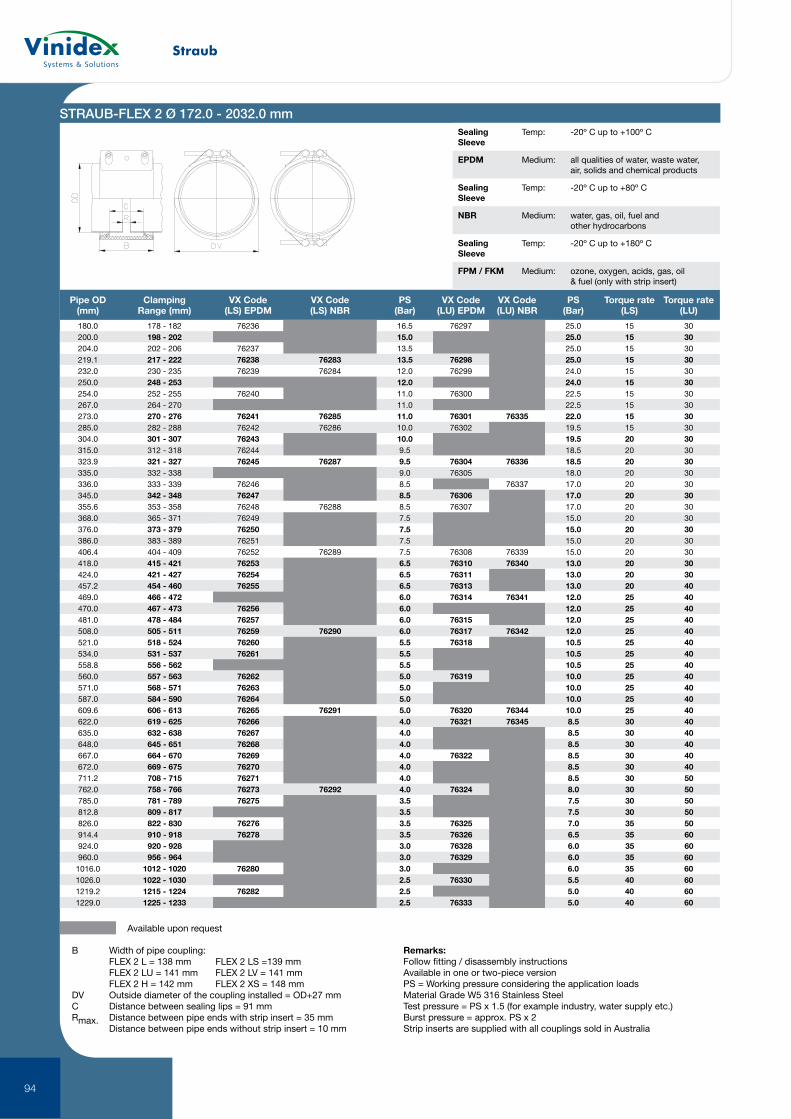
Straub
94
STRAUB-FLEX 2 Ø 172.0 - 2032.0 mm
Pipe OD (mm)
Clamping Range (mm)
VX Code (LS) EPDM
VX Code (LS) NBR
PS (Bar)
VX Code (LU) EPDM
VX Code (LU) NBR
PS (Bar)
Torque rate (LS)
Torque rate (LU)
180.0 178 - 182 76236 16.5 76297 25.0 15 30200.0 198 - 202 15.0 25.0 15 30204.0 202 - 206 76237 13.5 25.0 15 30219.1 217 - 222 76238 76283 13.5 76298 25.0 15 30232.0 230 - 235 76239 76284 12.0 76299 24.0 15 30250.0 248 - 253 12.0 24.0 15 30254.0 252 - 255 76240 11.0 76300 22.5 15 30267.0 264 - 270 11.0 22.5 15 30273.0 270 - 276 76241 76285 11.0 76301 76335 22.0 15 30285.0 282 - 288 76242 76286 10.0 76302 19.5 15 30304.0 301 - 307 76243 10.0 19.5 20 30315.0 312 - 318 76244 9.5 18.5 20 30323.9 321 - 327 76245 76287 9.5 76304 76336 18.5 20 30335.0 332 - 338 9.0 76305 18.0 20 30336.0 333 - 339 76246 8.5 76337 17.0 20 30345.0 342 - 348 76247 8.5 76306 17.0 20 30355.6 353 - 358 76248 76288 8.5 76307 17.0 20 30368.0 365 - 371 76249 7.5 15.0 20 30376.0 373 - 379 76250 7.5 15.0 20 30386.0 383 - 389 76251 7.5 15.0 20 30406.4 404 - 409 76252 76289 7.5 76308 76339 15.0 20 30418.0 415 - 421 76253 6.5 76310 76340 13.0 20 30424.0 421 - 427 76254 6.5 76311 13.0 20 30457.2 454 - 460 76255 6.5 76313 13.0 20 40469.0 466 - 472 6.0 76314 76341 12.0 25 40470.0 467 - 473 76256 6.0 12.0 25 40481.0 478 - 484 76257 6.0 76315 12.0 25 40508.0 505 - 511 76259 76290 6.0 76317 76342 12.0 25 40521.0 518 - 524 76260 5.5 76318 10.5 25 40534.0 531 - 537 76261 5.5 10.5 25 40558.8 556 - 562 5.5 10.5 25 40560.0 557 - 563 76262 5.0 76319 10.0 25 40571.0 568 - 571 76263 5.0 10.0 25 40587.0 584 - 590 76264 5.0 10.0 25 40609.6 606 - 613 76265 76291 5.0 76320 76344 10.0 25 40622.0 619 - 625 76266 4.0 76321 76345 8.5 30 40635.0 632 - 638 76267 4.0 8.5 30 40648.0 645 - 651 76268 4.0 8.5 30 40667.0 664 - 670 76269 4.0 76322 8.5 30 40672.0 669 - 675 76270 4.0 8.5 30 40711.2 708 - 715 76271 4.0 8.5 30 50762.0 758 - 766 76273 76292 4.0 76324 8.0 30 50785.0 781 - 789 76275 3.5 7.5 30 50812.8 809 - 817 3.5 7.5 30 50826.0 822 - 830 76276 3.5 76325 7.0 35 50914.4 910 - 918 76278 3.5 76326 6.5 35 60924.0 920 - 928 3.0 76328 6.0 35 60960.0 956 - 964 3.0 76329 6.0 35 60
1016.0 1012 - 1020 76280 3.0 6.0 35 601026.0 1022 - 1030 2.5 76330 5.5 40 601219.2 1215 - 1224 76282 2.5 5.0 40 601229.0 1225 - 1233 2.5 76333 5.0 40 60
Available upon request
B Width of pipe coupling: FLEX 2 L = 138 mm FLEX 2 LS =139 mm FLEX 2 LU = 141 mm FLEX 2 LV = 141 mm FLEX 2 H = 142 mm FLEX 2 XS = 148 mmDV Outside diameter of the coupling installed = OD+27 mmC Distance between sealing lips = 91 mmRmax. Distance between pipe ends with strip insert = 35 mm Distance between pipe ends without strip insert = 10 mm
Remarks:Follow fitting / disassembly instructionsAvailable in one or two-piece versionPS = Working pressure considering the application loadsMaterial Grade W5 316 Stainless SteelTest pressure = PS x 1.5 (for example industry, water supply etc.)Burst pressure = approx. PS x 2Strip inserts are supplied with all couplings sold in Australia
Sealing Sleeve
Temp: -20º C up to +100º C
EPDM Medium: all qualities of water, waste water, air, solids and chemical products
Sealing Sleeve
Temp: -20º C up to +80º C
NBR Medium: water, gas, oil, fuel and other hydrocarbons
Sealing Sleeve
Temp: -20º C up to +180º C
FPM / FKM Medium: ozone, oxygen, acids, gas, oil & fuel (only with strip insert)
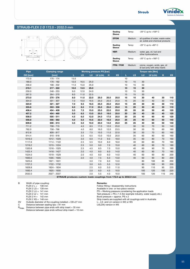
Straub
95
STRAUB-FLEX 2 Ø 172.0 - 2032.0 mm
B Width of pipe coupling: FLEX 2 L = 138 mm FLEX 2 LS = 139 mm FLEX 2 LU = 141 mm FLEX 2 LV = 141 mm FLEX 2 H = 142 mm FLEX 2 XS = 148 mmDV Outside diameter of the coupling installed = OD+27 mmC Distance between sealing lips = 91 mmRmax. Distance between pipe ends with strip insert = 35 mm Distance between pipe ends without strip insert = 10 mm
Remarks:Follow fitting / disassembly instructionsAvailable in one- or two-piece version PS = Working pressure considering the application loadsTest pressure = PS x 1.5 (for example industry, water supply etc.)Burst pressure = approx. PS x 2Strip inserts are supplied with all couplings sold in AustraliaL-, LS- and LU-version in W2 or W5LV(LDX)-version in W5
Sealing Sleeve
Temp: -20º C up to +100º C
EPDM Medium: all qualities of water, waste water, air, solids and chemical products
Sealing Sleeve
Temp: -20º C up to +80º C
NBR Medium: water, gas, oil, fuel and other hydrocarbons
Sealing Sleeve
Temp: -20º C up to +180º C
FPM / FKM Medium: ozone, oxygen, acids, gas, oil & fuel (only with strip insert)
STRAUB produces custom made couplings from 172.0 up to 2032.0 mm
Pipe Clamping range
OD [mm] [mm]
172.0 170 - 174180.0 178 - 182200.0 198 - 202219.1 217 - 222250.0 248 - 253267.0 264 - 270273.0 270 - 276304.0 301 - 307323.9 321 - 327355.6 353 - 358406.4 404 - 409457.2 454 - 460508.0 505 - 511558.8 556 - 562609.6 606 - 613711.2 708 - 715762.0 758 - 766812.8 809 - 817914.4 910 - 9181016.0 1012 - 10201117.6 1114 - 11221219.2 1215 - 12241320.8 1316 - 13251422.4 1418 - 14271524.0 1519 - 15291600.0 1595 - 16051625.6 1621 - 16311727.2 1722 - 17321828.8 1824 - 18341930.4 1925 - 19352032.0 2027 - 2037
Working pressure PS [bar]
L LS LU LV (LDX) H XS
13.012.0 16.5 25.011.0 15.0 25.010.0 13.5 25.09.0 12.0 24.08.0 11.0 22.58.0 11.0 22.0 25.0 25.0 25.07.0 10.0 19.5 25.0 25.0 25.07.0 9.5 18.5 25.0 25.0 25.06.0 8.5 17.0 25.0 25.0 25.05.5 7.5 15.0 25.0 22.0 25.05.0 6.5 13.0 25.0 19.0 25.04.5 6.0 12.0 24.0 17.0 25.04.0 5.5 10.5 22.0 16.0 25.03.5 5.0 10.0 20.0 14.0 25.0
4.0 8.5 17.0 12.0 25.04.0 8.0 16.0 12.0 23.53.5 7.5 15.0 11.0 22.03.5 6.5 13.0 10.0 20.03.0 6.0 11.0 9.0 18.02.5 5.5 10.0 8.0 16.02.5 5.0 9.0 7.0 15.02.5 4.5 8.5 7.0 15.02.0 4.0 8.0 6.0 14.02.0 4.0 8.0 6.0 14.02.0 4.0 7.5 6.0 13.0
3.0 7.0 6.0 13.03.0 6.5 5.5 12.02.5 6.0 5.0 11.02.0 6.0 4.5 10.02.0 5.5 4.0 10.0
Torque rate [Nm]
L LS LU LV (LDX) H XS
1010 15 3010 15 3010 15 3010 15 3015 15 3015 15 30 40 30 11015 20 30 40 30 11015 20 30 40 30 11015 20 30 40 30 11020 20 30 50 40 12020 20 40 50 40 12020 25 40 60 40 12025 25 40 60 50 14025 25 40 60 50 140
30 50 70 50 14030 50 70 60 16030 50 70 60 16035 60 80 60 16035 60 80 70 16040 60 80 70 18040 60 90 70 18040 60 90 70 18040 60 90 70 18040 60 90 80 20040 60 90 80 200
80 100 85 20080 100 90 20090 110 95 220
100 120 100 220100 120 110 240
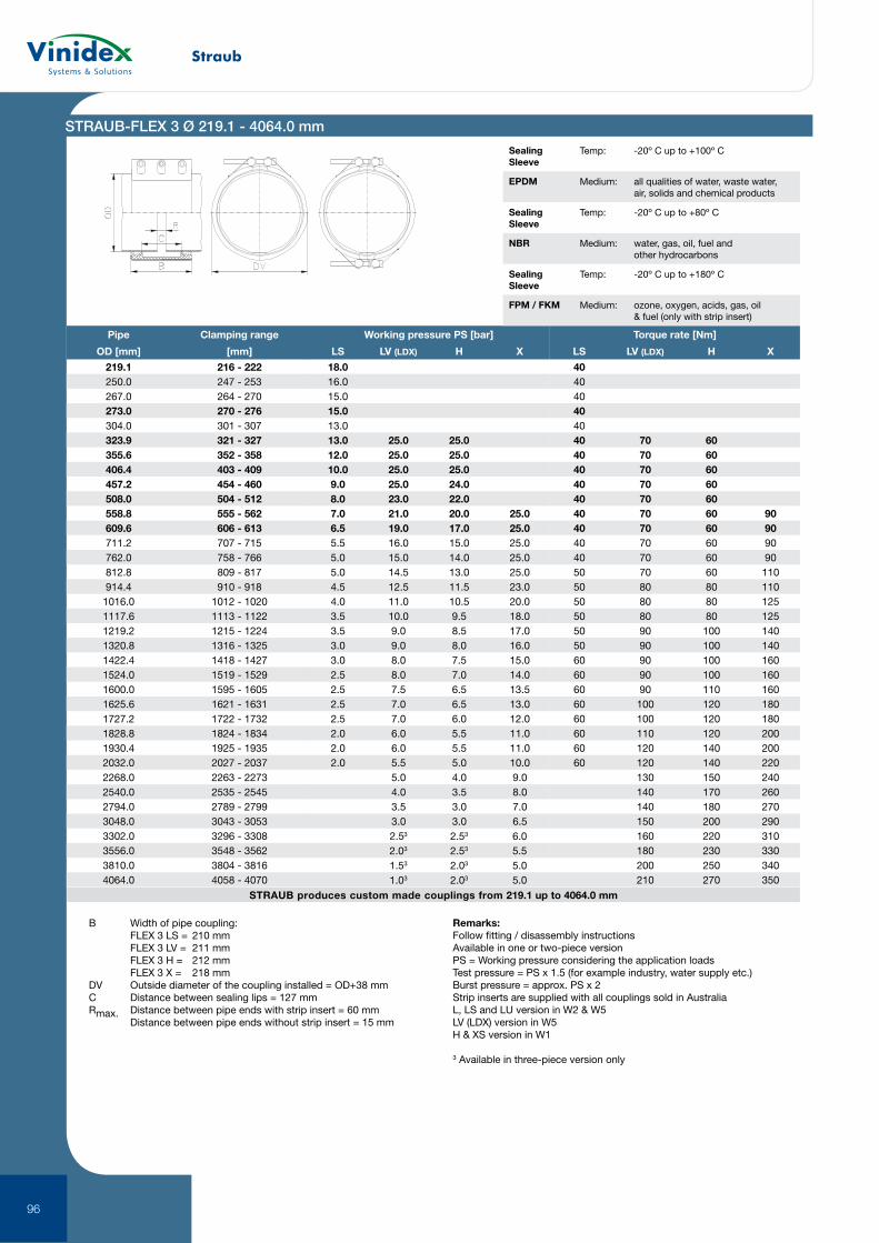
Straub
96
STRAUB produces custom made couplings from 219.1 up to 4064.0 mm
Pipe Clamping range
OD [mm] [mm]
219.1 216 - 222250.0 247 - 253267.0 264 - 270273.0 270 - 276304.0 301 - 307323.9 321 - 327355.6 352 - 358406.4 403 - 409457.2 454 - 460508.0 504 - 512558.8 555 - 562609.6 606 - 613711.2 707 - 715762.0 758 - 766812.8 809 - 817914.4 910 - 9181016.0 1012 - 10201117.6 1113 - 11221219.2 1215 - 12241320.8 1316 - 13251422.4 1418 - 14271524.0 1519 - 15291600.0 1595 - 16051625.6 1621 - 16311727.2 1722 - 17321828.8 1824 - 18341930.4 1925 - 19352032.0 2027 - 20372268.0 2263 - 22732540.0 2535 - 25452794.0 2789 - 27993048.0 3043 - 30533302.0 3296 - 33083556.0 3548 - 35623810.0 3804 - 38164064.0 4058 - 4070
Working pressure PS [bar]
LS LV (LDX) H X
18.016.015.015.013.013.0 25.0 25.012.0 25.0 25.010.0 25.0 25.09.0 25.0 24.08.0 23.0 22.07.0 21.0 20.0 25.06.5 19.0 17.0 25.05.5 16.0 15.0 25.05.0 15.0 14.0 25.05.0 14.5 13.0 25.04.5 12.5 11.5 23.04.0 11.0 10.5 20.03.5 10.0 9.5 18.03.5 9.0 8.5 17.03.0 9.0 8.0 16.03.0 8.0 7.5 15.02.5 8.0 7.0 14.02.5 7.5 6.5 13.52.5 7.0 6.5 13.02.5 7.0 6.0 12.02.0 6.0 5.5 11.02.0 6.0 5.5 11.02.0 5.5 5.0 10.0
5.0 4.0 9.04.0 3.5 8.03.5 3.0 7.03.0 3.0 6.52.53 2.53 6.02.03 2.53 5.51.53 2.03 5.01.03 2.03 5.0
Torque rate [Nm]
LS LV (LDX) H X
404040404040 70 6040 70 6040 70 6040 70 6040 70 6040 70 60 9040 70 60 9040 70 60 9040 70 60 9050 70 60 11050 80 80 11050 80 80 12550 80 80 12550 90 100 14050 90 100 14060 90 100 16060 90 100 16060 90 110 16060 100 120 18060 100 120 18060 110 120 20060 120 140 20060 120 140 220
130 150 240140 170 260140 180 270150 200 290160 220 310180 230 330200 250 340210 270 350
STRAUB-FLEX 3 Ø 219.1 - 4064.0 mm
Sealing Sleeve
Temp: -20º C up to +100º C
EPDM Medium: all qualities of water, waste water, air, solids and chemical products
Sealing Sleeve
Temp: -20º C up to +80º C
NBR Medium: water, gas, oil, fuel and other hydrocarbons
Sealing Sleeve
Temp: -20º C up to +180º C
FPM / FKM Medium: ozone, oxygen, acids, gas, oil & fuel (only with strip insert)
B Width of pipe coupling: FLEX 3 LS = 210 mm FLEX 3 LV = 211 mm FLEX 3 H = 212 mm FLEX 3 X = 218 mmDV Outside diameter of the coupling installed = OD+38 mmC Distance between sealing lips = 127 mmRmax. Distance between pipe ends with strip insert = 60 mm Distance between pipe ends without strip insert = 15 mm
Remarks:Follow fitting / disassembly instructionsAvailable in one or two-piece versionPS = Working pressure considering the application loadsTest pressure = PS x 1.5 (for example industry, water supply etc.)Burst pressure = approx. PS x 2Strip inserts are supplied with all couplings sold in AustraliaL, LS and LU version in W2 & W5LV (LDX) version in W5H & XS version in W1
3 Available in three-piece version only
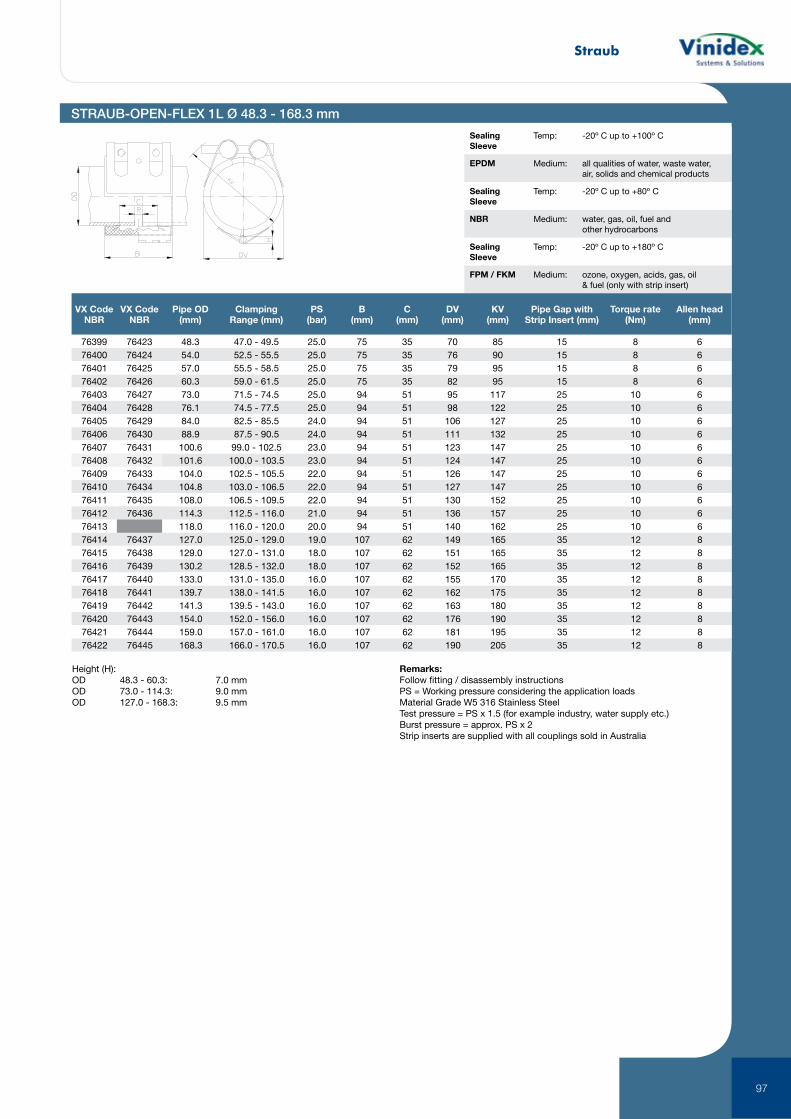
Straub
97
STRAUB-OPEN-FLEX 1L Ø 48.3 - 168.3 mm
Sealing Sleeve
Temp: -20º C up to +100º C
EPDM Medium: all qualities of water, waste water, air, solids and chemical products
Sealing Sleeve
Temp: -20º C up to +80º C
NBR Medium: water, gas, oil, fuel and other hydrocarbons
Sealing Sleeve
Temp: -20º C up to +180º C
FPM / FKM Medium: ozone, oxygen, acids, gas, oil & fuel (only with strip insert)
VX Code NBR
VX Code NBR
Pipe OD (mm)
Clamping Range (mm)
PS (bar)
B (mm)
C (mm)
DV (mm)
KV (mm)
Pipe Gap with Strip Insert (mm)
Torque rate (Nm)
Allen head (mm)
76399 76423 48.3 47.0 - 49.5 25.0 75 35 70 85 15 8 676400 76424 54.0 52.5 - 55.5 25.0 75 35 76 90 15 8 676401 76425 57.0 55.5 - 58.5 25.0 75 35 79 95 15 8 676402 76426 60.3 59.0 - 61.5 25.0 75 35 82 95 15 8 676403 76427 73.0 71.5 - 74.5 25.0 94 51 95 117 25 10 676404 76428 76.1 74.5 - 77.5 25.0 94 51 98 122 25 10 676405 76429 84.0 82.5 - 85.5 24.0 94 51 106 127 25 10 676406 76430 88.9 87.5 - 90.5 24.0 94 51 111 132 25 10 676407 76431 100.6 99.0 - 102.5 23.0 94 51 123 147 25 10 676408 76432 101.6 100.0 - 103.5 23.0 94 51 124 147 25 10 676409 76433 104.0 102.5 - 105.5 22.0 94 51 126 147 25 10 676410 76434 104.8 103.0 - 106.5 22.0 94 51 127 147 25 10 676411 76435 108.0 106.5 - 109.5 22.0 94 51 130 152 25 10 676412 76436 114.3 112.5 - 116.0 21.0 94 51 136 157 25 10 676413 118.0 116.0 - 120.0 20.0 94 51 140 162 25 10 676414 76437 127.0 125.0 - 129.0 19.0 107 62 149 165 35 12 876415 76438 129.0 127.0 - 131.0 18.0 107 62 151 165 35 12 876416 76439 130.2 128.5 - 132.0 18.0 107 62 152 165 35 12 876417 76440 133.0 131.0 - 135.0 16.0 107 62 155 170 35 12 876418 76441 139.7 138.0 - 141.5 16.0 107 62 162 175 35 12 876419 76442 141.3 139.5 - 143.0 16.0 107 62 163 180 35 12 876420 76443 154.0 152.0 - 156.0 16.0 107 62 176 190 35 12 876421 76444 159.0 157.0 - 161.0 16.0 107 62 181 195 35 12 876422 76445 168.3 166.0 - 170.5 16.0 107 62 190 205 35 12 8
Height (H):OD 48.3 - 60.3: 7.0 mmOD 73.0 - 114.3: 9.0 mmOD 127.0 - 168.3: 9.5 mm
Remarks:Follow fitting / disassembly instructionsPS = Working pressure considering the application loadsMaterial Grade W5 316 Stainless SteelTest pressure = PS x 1.5 (for example industry, water supply etc.)Burst pressure = approx. PS x 2Strip inserts are supplied with all couplings sold in Australia
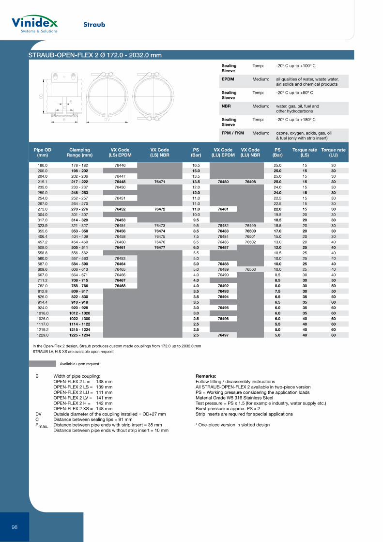
Straub
98
STRAUB-OPEN-FLEX 2 Ø 172.0 - 2032.0 mm
Pipe OD (mm)
Clamping Range (mm)
VX Code (LS) EPDM
VX Code (LS) NBR
PS (Bar)
VX Code (LU) EPDM
VX Code (LU) NBR
PS (Bar)
Torque rate (LS)
Torque rate (LU)
180.0 178 - 182 76446 16.5 25.0 15 30200.0 198 - 202 15.0 25.0 15 30204.0 202 - 206 76447 13.5 25.0 15 30219.1 217 - 222 76448 76471 13.5 76480 76498 25.0 15 30235.0 233 - 237 76450 12.0 24.0 15 30250.0 248 - 253 12.0 24.0 15 30254.0 252 - 257 76451 11.0 22.5 15 30267.0 264 - 270 11.0 22.5 15 30273.0 270 - 276 76452 76472 11.0 76481 22.0 15 30304.0 301 - 307 10.0 19.5 20 30317.0 314 - 320 76453 9.5 18.5 20 30323.9 321 - 327 76454 76473 9.5 76482 76499 18.5 20 30355.6 353 - 358 76456 76474 8.5 76483 76500 17.0 20 30406.4 404 - 409 76458 76475 7.5 76484 76501 15.0 20 30457.2 454 - 460 76460 76476 6.5 76486 76502 13.0 20 40508.0 505 - 511 76461 76477 6.0 76487 12.0 25 40558.8 556 - 562 5.5 10.5 25 40560.0 557 - 563 76453 5.0 10.0 25 40587.0 584 - 590 76464 5.0 76488 10.0 25 40609.6 606 - 613 76465 5.0 76489 76503 10.0 25 40667.0 664 - 671 76466 4.0 76490 8.5 30 40711.2 708 - 715 76467 4.0 8.5 30 50762.0 758 - 766 76468 4.0 76492 8.0 30 50812.8 809 - 817 3.5 76493 7.5 30 50826.0 822 - 830 3.5 76494 6.5 35 50914.4 910 - 918 3.5 6.5 35 60924.0 920 - 928 3.0 76495 6.0 35 601016.0 1012 - 1020 3.0 6.0 35 601026.0 1022 - 1300 2.5 76496 6.0 40 601117.0 1114 - 1122 2.5 5.5 40 601219.2 1215 - 1224 2.5 5.0 40 601229.0 1225 - 1234 2.5 76497 5.0 40 60
In the Open-Flex 2 design, Straub produces custom made couplings from 172.0 up to 2032.0 mmSTRAUB LV, H & XS are available upon request
Available upon request
B Width of pipe coupling: OPEN-FLEX 2 L = 138 mm OPEN-FLEX 2 LS = 139 mm OPEN-FLEX 2 LU = 141 mm OPEN-FLEX 2 LV = 141 mm OPEN-FLEX 2 H = 142 mm OPEN-FLEX 2 XS = 148 mmDV Outside diameter of the coupling installed = OD+27 mmC Distance between sealing lips = 91 mmRmax. Distance between pipe ends with strip insert = 35 mm Distance between pipe ends without strip insert = 10 mm
Remarks:Follow fitting / disassembly instructionsAll STRAUB-OPEN-FLEX 2 available in two-piece versionPS = Working pressure considering the application loadsMaterial Grade W5 316 Stainless SteelTest pressure = PS x 1.5 (for example industry, water supply etc.)Burst pressure = approx. PS x 2Strip inserts are required for special applications
4 One-piece version in slotted design
Sealing Sleeve
Temp: -20º C up to +100º C
EPDM Medium: all qualities of water, waste water, air, solids and chemical products
Sealing Sleeve
Temp: -20º C up to +80º C
NBR Medium: water, gas, oil, fuel and other hydrocarbons
Sealing Sleeve
Temp: -20º C up to +180º C
FPM / FKM Medium: ozone, oxygen, acids, gas, oil & fuel (only with strip insert)
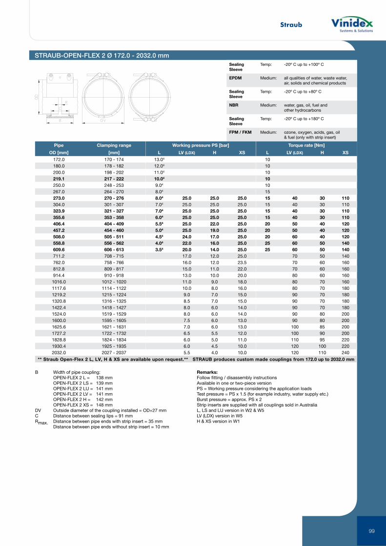
Straub
99
STRAUB-OPEN-FLEX 2 Ø 172.0 - 2032.0 mm
B Width of pipe coupling: OPEN-FLEX 2 L = 138 mm OPEN-FLEX 2 LS = 139 mm OPEN-FLEX 2 LU = 141 mm OPEN-FLEX 2 LV = 141 mm OPEN-FLEX 2 H = 142 mm OPEN-FLEX 2 XS = 148 mmDV Outside diameter of the coupling installed = OD+27 mmC Distance between sealing lips = 91 mmRmax. Distance between pipe ends with strip insert = 35 mm Distance between pipe ends without strip insert = 10 mm
Remarks:Follow fitting / disassembly instructionsAvailable in one or two-piece versionPS = Working pressure considering the application loadsTest pressure = PS x 1.5 (for example industry, water supply etc.)Burst pressure = approx. PS x 2Strip inserts are supplied with all couplings sold in AustraliaL, LS and LU version in W2 & W5LV (LDX) version in W5H & XS version in W1
Sealing Sleeve
Temp: -20º C up to +100º C
EPDM Medium: all qualities of water, waste water, air, solids and chemical products
Sealing Sleeve
Temp: -20º C up to +80º C
NBR Medium: water, gas, oil, fuel and other hydrocarbons
Sealing Sleeve
Temp: -20º C up to +180º C
FPM / FKM Medium: ozone, oxygen, acids, gas, oil & fuel (only with strip insert)
** Straub Open-Flex 2 L, LV, H & XS are available upon request.** STRAUB produces custom made couplings from 172.0 up to 2032.0 mm
Pipe Clamping range
OD [mm] [mm]
172.0 170 - 174180.0 178 - 182200.0 198 - 202219.1 217 - 222250.0 248 - 253267.0 264 - 270273.0 270 - 276304.0 301 - 307323.9 321 - 327355.6 353 - 358406.4 404 - 409457.2 454 - 460508.0 505 - 511558.8 556 - 562609.6 606 - 613711.2 708 - 715762.0 758 - 766812.8 809 - 817914.4 910 - 9181016.0 1012 - 10201117.6 1114 - 11221219.2 1215 - 12241320.8 1316 - 13251422.4 1418 - 14271524.0 1519 - 15291600.0 1595 - 16051625.6 1621 - 16311727.2 1722 - 17321828.8 1824 - 18341930.4 1925 - 19352032.0 2027 - 2037
Working pressure PS [bar]
L LV (LDX) H XS
13.04
12.04
11.04
10.04
9.04
8.04
8.04 25.0 25.0 25.07.04 25.0 25.0 25.07.04 25.0 25.0 25.06.04 25.0 25.0 25.05.54 25.0 22.0 25.05.04 25.0 19.0 25.04.54 24.0 17.0 25.04.04 22.0 16.0 25.03.54 20.0 14.0 25.0
17.0 12.0 25.016.0 12.0 23.515.0 11.0 22.013.0 10.0 20.011.0 9.0 18.010.0 8.0 16.09.0 7.0 15.08.5 7.0 15.08.0 6.0 14.08.0 6.0 14.07.5 6.0 13.07.0 6.0 13.06.5 5.5 12.06.0 5.0 11.06.0 4.5 10.05.5 4.0 10.0
Torque rate [Nm]
L LV (LDX) H XS
10101010101515 40 30 11015 40 30 11015 40 30 11015 40 30 11020 50 40 12020 50 40 12020 60 40 12025 60 50 14025 60 50 140
70 50 14070 60 16070 60 16080 60 16080 70 16080 70 18090 70 18090 70 18090 70 18090 80 20090 80 200100 85 200100 90 200110 95 220120 100 220120 110 240

Straub
100
** Straub Open-Flex 3 L, LV, H & XS are available upon request.** STRAUB produces custom made couplings from 219.1 up to 4064.0 mm
Pipe Clamping range
OD [mm] [mm]
219.1 216 - 222250.0 247 - 253267.0 264 - 270273.0 270 - 276304.0 301 - 307323.9 321 - 327355.6 352 - 358406.4 403 - 409457.2 454 - 460508.0 504 - 512558.8 555 - 562609.6 606 - 613711.2 707 - 715762.0 758 - 766812.8 809 - 817914.4 910 - 9181016.0 1012 - 10201117.6 1113 - 11221219.2 1215 - 12241320.8 1316 - 13251422.4 1418 - 14271524.0 1519 - 15291600.0 1595 - 16051625.6 1621 - 16311727.2 1722 - 17321828.8 1824 - 18341930.4 1925 - 19352032.0 2027 - 20372268.0 2263 - 22732540.0 2535 - 25452794.0 2789 - 27993048.0 3043 - 30533302.0 3296 - 33083556.0 3548 - 35623810.0 3804 - 38164064.0 4058 - 4070
Working pressure PS [bar]
LS LV (LDX) H X
18.016.015.015.013.013.0 25.0 25.012.0 25.0 25.010.0 25.0 25.09.0 25.0 24.08.04 23.0 22.07.04 21.0 20.0 25.06.54 19.0 17.0 25.05.54 16.0 15.0 25.05.04 15.0 14.0 25.05.04 14.5 13.0 25.04.54 12.5 11.5 23.04.04 11.0 10.5 20.03.54 10.0 9.5 18.03.54 9.0 8.5 17.03.0 9.0 8.0 16.03.0 8.0 7.5 15.02.5 8.0 7.0 14.02.5 7.5 6.5 13.52.5 7.0 6.5 13.02.5 7.0 6.0 12.02.0 6.0 5.5 11.02.0 6.0 5.5 11.02.0 5.5 5.0 10.0
5.0 4.0 9.04.0 3.5 8.03.5 3.0 7.03.0 3.0 6.52.53 2.53 6.02.03 2.53 5.51.53 2.03 5.01.03 2.03 5.0
Torque rate [Nm]
LS LV (LDX) H X
404040404040 70 6040 70 6040 70 6040 70 6040 70 6040 70 60 9040 70 60 9040 70 60 9040 70 60 9050 70 60 11050 80 80 11050 80 80 12550 80 80 12550 90 100 14050 90 100 14060 90 100 16060 90 100 16060 90 110 16060 100 120 18060 100 120 18060 110 120 20060 120 140 20060 120 140 220
130 150 240140 170 260140 180 270150 200 290160 220 310180 230 330200 250 340210 270 350
STRAUB-OPEN-FLEX 3 Ø 219.1 - 4064.0 mm
B Width of pipe coupling: OPEN-FLEX 3 LS = 210 mm OPEN-FLEX 3 LV = 211 mm OPEN-FLEX 3 H = 221 mm OPEN-FLEX 3 X = 218 mmDV Outside diameter of the coupling installed = OD+38 mmC Distance between sealing lips = 127 mmRmax. Distance between pipe ends with strip insert = 60 mm Distance between pipe ends without strip insert = 15 mm
Remarks:Follow fitting / disassembly instructionsAll STRAUB-OPEN-FLEX 3 available in two-piece versionPS = Working pressure considering the application loadsTest pressure = PS x 1.5 (for example industry, water supply etc.)Burst pressure = approx. PS x 2LS-version in W2 or W5LV(LDX)-version in W5H- and X-version in W13 Available in three-piece version only4 One-piece version in slotted design
Sealing Sleeve
Temp: -20º C up to +100º C
EPDM Medium: all qualities of water, waste water, air, solids and chemical products
Sealing Sleeve
Temp: -20º C up to +80º C
NBR Medium: water, gas, oil, fuel and other hydrocarbons
Sealing Sleeve
Temp: -20º C up to +180º C
FPM / FKM Medium: ozone, oxygen, acids, gas, oil & fuel (only with strip insert)
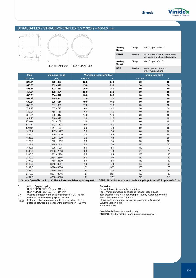
Straub
101
** Straub Open-Flex 3.5 L, LV, H & XS are available upon request.** STRAUB produces custom made couplings from 323.9 up to 4064.0 mm
Pipe Clamping range
OD [mm] [mm]
323.95 320 - 327355.65 352 - 370406.45 402 - 410457.25 453 - 461508.05 504 - 512558.85 555 - 563609.65 605 - 614655.05 651 - 659711.25 707 - 715762.05 758 - 766812.85 809 - 817914.45 910 - 9181016.05 1011 - 10211117.65 1112 - 11231219.25 1214 - 12241422.4 1417 - 14271524.0 1519 - 15291625.0 1620 - 16301727.2 1722 - 17321828.8 1824 - 18341930.4 1925 - 19352032.0 2026 - 20382268.0 2262 - 22742540.0 2534 - 25462794.0 1788 - 28003048.0 3042 - 30543302.0 3296 - 33083556.0 3550 - 35623810.0 3804 - 38164064.0 4058 - 4070
Working pressure PS [bar]
LV (LDX) H
25.0 25.025.0 25.025.0 25.025.0 25.023.0 23.021.0 21.019.0 19.017.0 17.016.0 16.015.0 15.014.0 14.012.0 12.011.0 11.010.0 10.09.0 9.07.0 8.07.0 7.56.0 7.06.0 6.55.0 6.04.5 5.54.0 5.03.5 4.53.0 4.02.5 3.52.0 3.01.53 3.03
1.53 3.03
1.03 2.53
1.03 2.53
Torque rate [Nm]
LV (LDX) H
50 5050 5050 5050 5050 5050 5050 5050 5050 5050 5050 5060 6060 6070 7080 8080 8080 8090 9090 90
110 100110 110120 120130 130140 140140 140160 160170 170180 180190 190210 210
STRAUB-FLEX / STRAUB-OPEN-FLEX 3.5 Ø 323.9 - 4064.0 mm
Sealing Sleeve
Temp: -20º C up to +100º C
EPDM Medium: all qualities of water, waste water, air, solids and chemical products
Sealing Sleeve
Temp: -20º C up to +80º C
NBR Medium: water, gas, oil, fuel and other hydrocarbons
B Width of pipe coupling: FLEX / OPEN-FLEX 3.5 LV = 310 mm FLEX / OPEN-FLEX 3.5 H = 311 mmDV Outside diameter of the coupling installed = OD+38 mmC Distance between sealing lips = 227 mmRmax. Distance between pipe ends with strip insert = 120 mm Distance between pipe ends without strip insert = 20 mm
Remarks:Follow fitting / disassembly instructionsPS = Working pressure considering the application loadsTest pressure = PS x 1.5 (for example industry, water supply etc.)Burst pressure = approx. PS x 2Strip inserts are required for special applications (included)LV(LDX)-version in W5H-version in W1
3 Available in three-piece version only5 STRAUB-FLEX available in one-piece version as well
FLEX to 1219.2 mm FLEX / OPEN-FLEX
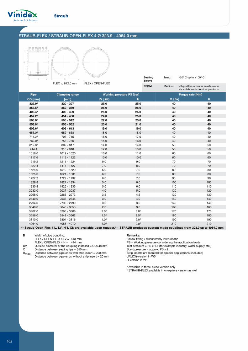
Straub
102
** Straub Open-Flex 4 L, LV, H & XS are available upon request.** STRAUB produces custom made couplings from 323.9 up to 4064.0 mm
Pipe Clamping range
OD [mm] [mm]
323.95 320 - 327355.65 352 - 359406.45 403 - 409457.25 454 - 460508.05 505 - 512558.85 555 - 562609.65 606 - 613655.05 652 - 658711.25 707 - 715762.05 758 - 766812.85 809 - 817914.4 910 - 9181016.0 1012 - 10201117.6 1113 - 11221219.2 1215 - 12241422.4 1418 - 14271524.0 1519 - 15291625.0 1621 - 16311727.2 1722 - 17321828.8 1824 - 18341930.4 1925 - 19352032.0 2027 - 20372268.0 2263 - 22732540.0 2535 - 25452794.0 2798 - 27993048.0 3043 - 30533302.0 3296 - 33083556.0 3548 - 35623810.0 3804 - 38164064.0 4058 - 4070
Working pressure PS [bar]
LV (LDX) H
25.0 25.025.0 25.025.0 25.024.0 25.022.0 23.020.0 21.019.0 19.018.0 18.016.0 17.015.0 16.014.0 14.012.0 13.010.0 11.010.0 10.09.0 9.07.0 8.06.0 7.06.0 7.06.0 7.05.0 6.05.0 6.04.0 5.03.5 4.53.0 4.03.0 3.02.0 3.02.03 3.03
1.53 2.53
1.03 2.03
1.03 2.03
Torque rate [Nm]
LV (LDX) H
40 4040 4040 4040 4040 4040 4040 4040 4040 4040 4050 5050 5060 6060 6070 7070 7080 8080 8090 90
100 100110 110120 120130 130140 140140 140160 160170 170180 180190 190210 210
STRAUB-FLEX / STRAUB-OPEN-FLEX 4 Ø 323.9 - 4064.0 mm
B Width of pipe coupling: FLEX / OPEN-FLEX 4 LV = 443 mm FLEX / OPEN-FLEX 4 H = 444 mmDV Outside diameter of the coupling installed = OD+48 mmC Distance between sealing lips = 350 mmRmax. Distance between pipe ends with strip insert = 200 mm Distance between pipe ends without strip insert = 20 mm
Remarks:Follow fitting / disassembly instructionsPS = Working pressure considering the application loadsTest pressure = PS x 1.5 (for example industry, water supply etc.)Burst pressure = approx. PS x 2Strip inserts are required for special applications (included)LV(LDX)-version in W5H-version in W1
3 Available in three-piece version only5 STRAUB-FLEX available in one-piece version as well
Sealing Sleeve
Temp: -20º C up to +100º C
EPDM Medium: all qualities of water, waste water, air, solids and chemical products
FLEX to 812.0 mm FLEX / OPEN-FLEX
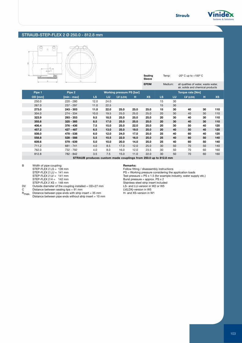
Straub
103
STRAUB-STEP-FLEX 2 Ø 250.0 - 812.8 mm
Pipe 1 Pipe 2
OD [mm] [min - max]
250.0 220 - 280267.0 237 - 297273.0 243 - 303304.0 274 - 334323.9 293 - 353355.6 325 - 385406.4 376 - 436457.2 427 - 487508.0 478 - 538558.8 528 - 588609.6 579 - 639711.2 681 - 741762.0 732 - 792812.8 782 - 842
Working pressure PS [bar]
LS LU LV (LDX) H XS
12.0 24.011.0 22.511.0 22.0 25.0 25.0 25.010.0 19.5 25.0 25.0 25.09.5 18.5 25.0 25.0 25.08.5 17.0 25.0 25.0 25.07.5 15.0 25.0 22.0 25.06.5 13.0 25.0 19.0 25.06.0 12.0 24.0 17.0 25.05.5 10.5 22.0 16.0 25.05.0 10.0 20.0 14.0 25.04.0 8.5 17.0 12.0 25.04.0 8.0 16.0 12.0 23.53.5 7.5 15.0 11.0 22.0
STRAUB produces custom made couplings from 250.0 up to 812.8 mm
Torque rate [Nm]
LS LU LV (LDX) H XS
15 3015 3015 30 40 30 11020 30 40 30 11020 30 40 30 11020 30 40 30 11020 30 50 40 12020 40 50 40 12025 40 60 40 12025 40 60 50 14025 40 60 50 14030 50 70 50 14030 50 70 60 16030 50 70 60 160
Sealing Sleeve
Temp: -20º C up to +100º C
EPDM Medium: all qualities of water, waste water, air, solids and chemical products
B Width of pipe coupling: STEP-FLEX 2 LS = 139 mm STEP-FLEX 2 LU = 141 mm STEP-FLEX 2 LV = 141 mm STEP-FLEX 2 H = 142 mm STEP-FLEX 2 XS = 148 mmDV Outside diameter of the coupling installed = OD+27 mmC Distance between sealing lips = 91 mmRmax. Distance between pipe ends with strip insert = 35 mm Distance between pipe ends without strip insert = 10 mm
Remarks:Follow fitting / disassembly instructionsPS = Working pressure considering the application loadsTest pressure = PS x 1.5 (for example industry, water supply etc.)Burst pressure = approx. PS x 2Stainless steel strip insert includedLS- and LU-version in W2 or W5LV(LDX)-version in W5H- and XS-version in W1
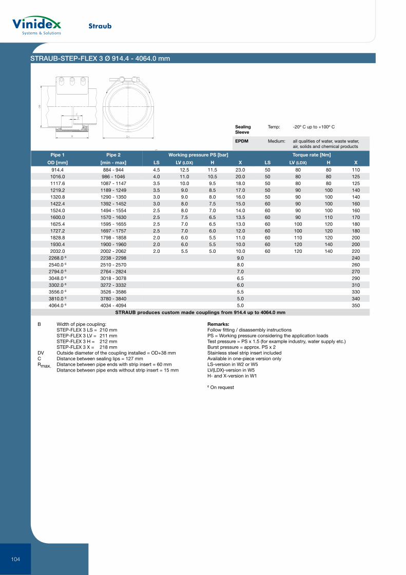
Straub
104
STRAUB produces custom made couplings from 914.4 up to 4064.0 mm
STRAUB-STEP-FLEX 3 Ø 914.4 - 4064.0 mm
Pipe 1 Pipe 2
OD [mm] [min - max]
914.4 884 - 9441016.0 986 - 10461117.6 1087 - 11471219.2 1189 - 12491320.8 1290 - 13501422.4 1392 - 14521524.0 1494 - 15541600.0 1570 - 16301625.4 1595 - 16551727.2 1697 - 17571828.8 1798 - 18581930.4 1900 - 19602032.0 2002 - 2062
2268.0 6 2238 - 22982540.0 6 2510 - 25702794.0 6 2764 - 28243048.0 6 3018 - 30783302.0 6 3272 - 33323556.0 6 3526 - 35863810.0 6 3780 - 38404064.0 6 4034 - 4094
Working pressure PS [bar]
LS LV (LDX) H X
4.5 12.5 11.5 23.04.0 11.0 10.5 20.03.5 10.0 9.5 18.03.5 9.0 8.5 17.03.0 9.0 8.0 16.03.0 8.0 7.5 15.02.5 8.0 7.0 14.02.5 7.5 6.5 13.52.5 7.0 6.5 13.02.5 7.0 6.0 12.02.0 6.0 5.5 11.02.0 6.0 5.5 10.02.0 5.5 5.0 10.0
9.08.07.06.56.05.55.05.0
Torque rate [Nm]
LS LV (LDX) H X
50 80 80 11050 80 80 12550 80 80 12550 90 100 14050 90 100 14060 90 100 16060 90 100 16060 90 110 17060 100 120 18060 100 120 18060 110 120 20060 120 140 20060 120 140 220
240260270290310330340350
B Width of pipe coupling: STEP-FLEX 3 LS = 210 mm STEP-FLEX 3 LV = 211 mm STEP-FLEX 3 H = 212 mm STEP-FLEX 3 X = 218 mmDV Outside diameter of the coupling installed = OD+38 mmC Distance between sealing lips = 127 mmRmax. Distance between pipe ends with strip insert = 60 mm Distance between pipe ends without strip insert = 15 mm
Remarks:Follow fitting / disassembly instructionsPS = Working pressure considering the application loadsTest pressure = PS x 1.5 (for example industry, water supply etc.)Burst pressure = approx. PS x 2Stainless steel strip insert includedAvailable in one-piece version onlyLS-version in W2 or W5LV(LDX)-version in W5H- and X-version in W1
6 On request
Sealing Sleeve
Temp: -20º C up to +100º C
EPDM Medium: all qualities of water, waste water, air, solids and chemical products
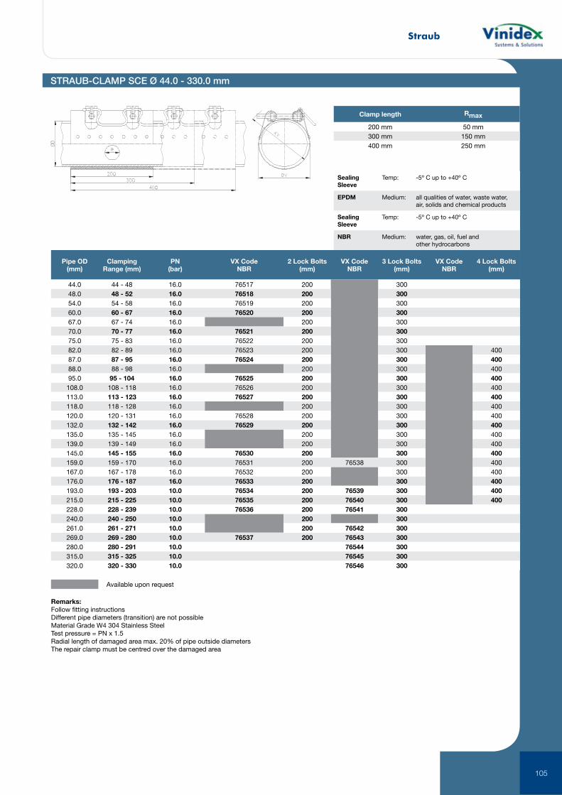
Straub
105
Remarks:Follow fitting instructionsDifferent pipe diameters (transition) are not possibleMaterial Grade W4 304 Stainless SteelTest pressure = PN x 1.5 Radial length of damaged area max. 20% of pipe outside diametersThe repair clamp must be centred over the damaged area
STRAUB-CLAMP SCE Ø 44.0 - 330.0 mm
Clamp length Rmax
200 mm 50 mm300 mm 150 mm400 mm 250 mm
Pipe OD (mm)
Clamping Range (mm)
PN (bar)
VX Code NBR
2 Lock Bolts (mm)
VX Code NBR
3 Lock Bolts (mm)
VX Code NBR
4 Lock Bolts (mm)
44.0 44 - 48 16.0 76517 200 30048.0 48 - 52 16.0 76518 200 30054.0 54 - 58 16.0 76519 200 30060.0 60 - 67 16.0 76520 200 30067.0 67 - 74 16.0 200 30070.0 70 - 77 16.0 76521 200 30075.0 75 - 83 16.0 76522 200 30082.0 82 - 89 16.0 76523 200 300 40087.0 87 - 95 16.0 76524 200 300 40088.0 88 - 98 16.0 200 300 40095.0 95 - 104 16.0 76525 200 300 400108.0 108 - 118 16.0 76526 200 300 400113.0 113 - 123 16.0 76527 200 300 400118.0 118 - 128 16.0 200 300 400120.0 120 - 131 16.0 76528 200 300 400132.0 132 - 142 16.0 76529 200 300 400135.0 135 - 145 16.0 200 300 400139.0 139 - 149 16.0 200 300 400145.0 145 - 155 16.0 76530 200 300 400159.0 159 - 170 16.0 76531 200 76538 300 400167.0 167 - 178 16.0 76532 200 300 400176.0 176 - 187 16.0 76533 200 300 400193.0 193 - 203 10.0 76534 200 76539 300 400215.0 215 - 225 10.0 76535 200 76540 300 400228.0 228 - 239 10.0 76536 200 76541 300240.0 240 - 250 10.0 200 300261.0 261 - 271 10.0 200 76542 300269.0 269 - 280 10.0 76537 200 76543 300280.0 280 - 291 10.0 76544 300315.0 315 - 325 10.0 76545 300320.0 320 - 330 10.0 76546 300
Available upon request
Sealing Sleeve
Temp: -5º C up to +40º C
EPDM Medium: all qualities of water, waste water, air, solids and chemical products
Sealing Sleeve
Temp: -5º C up to +40º C
NBR Medium: water, gas, oil, fuel and other hydrocarbons
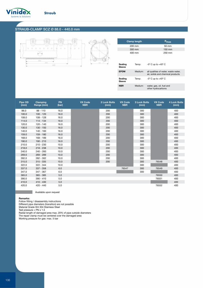
Straub
106
Remarks:Follow fitting / disassembly instructionsDifferent pipe diameters (transition) are not possibleMaterial Grade W4 304 Stainless SteelTest pressure = PN x 1.5 Radial length of damaged area max. 20% of pipe outside diametersThe repair clamp must be centered over the damaged areaWorking pressure for gas: max. 5 bar
Pipe OD (mm)
Clamping Range (mm)
PN (bar)
VX Code NBR
2 Lock Bolts (mm)
VX Code NBR
3 Lock Bolts (mm)
VX Code NBR
4 Lock Bolts (mm)
88.0 88 - 110 16.0 200 300 400100.0 100 - 120 16.0 200 300 400108.0 108 - 128 16.0 200 300 400114.0 114 - 134 16.0 200 300 400120.0 120 - 140 16.0 200 300 400130.0 130 - 150 16.0 200 300 400140.0 140 - 160 16.0 200 300 400159.0 159 - 180 16.0 200 300 400168.0 168 - 189 16.0 200 300 400190.0 190 - 210 16.0 200 300 400210.0 210 - 230 10.0 200 300 400218.0 218 - 238 10.0 200 300 400240.0 240 - 260 10.0 200 300 400269.0 269 - 289 10.0 200 300 400282.0 282 - 302 10.0 200 300 400315.0 315 - 335 10.0 200 300 76548 400322.0 322 - 344 10.0 300 400337.0 337 - 358 6.0 76547 300 76549 400347.0 347 - 367 6.0 300 400365.0 365 - 385 5.0 76550 400390.0 390 - 410 5.0 76551 400410.0 410 - 430 5.0 400420.0 420 - 440 5.0 76552 400
Available upon request
STRAUB-CLAMP SCZ Ø 88.0 - 440.0 mm
Clamp length Rmax
200 mm 50 mm300 mm 150 mm400 mm 250 mm
Sealing Sleeve
Temp: -5º C up to +40º C
EPDM Medium: all qualities of water, waste water, air, solids and chemical products
Sealing Sleeve
Temp: -5º C up to +40º C
NBR Medium: water, gas, oil, fuel and other hydrocarbons

Notes
iv
Vinidex Pty LimitedABN 42 000 664 942
HEAD OFFICELevel 4, 26 College Street Darlinghurst NSW 2010 PO Box 747, Darlinghurst NSW 1300
Reception: +61 2 8278 0500
CUSTOMER SERVICEP 13 11 69 | F 13 24 43E [email protected] W www.vinidex.com.au
Limitation of LiabilityThis product catalogue has been compiled by Vinidex Pty Limited (“the Company”) to promote better understanding of the technical aspects of the Company’s products to assist users in obtaining from them the best possible performance. The product catalogue is supplied subject to acknowledgement of the following conditions: 1 The product catalogue is protected by copyright and may not be copied or reproduced in any form or by any means in whole or in part without prior consent in writing by the Company. 2 Product specifications, usage data and advisory information may change from time to time with advances in research and field experience. The Company reserves the right to make such changes at any time without further notice. 3 Correct usage of the Company’s products involves engineering judgements, which can not be properly made without full knowledge of all the conditions pertaining to each specific installation. The Company expressly disclaims all and any liability to any person whether supplied with this publication or not in respect of anything and all of the consequences of anything done or omitted to be done by any such person in reliance whether whole or part of the contents of this publication. 4 No offer to trade, nor any conditions of trading, are expressed or implied by the issue of content of this product catalogue. Nothing herein shall override the Company’s Condition of Sale, which may be obtained from the Registered Office or any Sales Office of the Company. 5 This product catalogue is and shall remain the property of the Company, and shall be surrendered on demand to the Company. 6 Information supplied in this product catalogue does not override a job specification, where such conflict arises; consult the authority supervising the job. © Copyright Vinidex Pty Limited.
AUSTRALIAN OPERATIONS
Sydney
254 Woodpark Rd Smithfield NSW 2164
Wagga Wagga
280 Byrnes Rd Wagga Wagga NSW 2650 Melbourne
Unit 1, 10 Duerdin St Notting Hill VIC 3168
231-245 St Albans Rd Sunshine VIC 3020
Adelaide
9–11 Kaurna Ave Edinburgh SA 5111
Launceston
15 Thistle St Sth Launceston TAS 7249
Brisbane
224 Musgrave Rd Coopers Plains QLD 4108
Townsville
49 Enterprise Ave Bohle QLD 4816
Toowoomba
Lot 2 Witmack Rd Wellcamp QLD 4350 Rodney Industries
19 Valente Close Chermside QLD 4032
Darwin
3846 Marjorie St Pinelands NT 0829
Perth
Sainsbury Rd O’Connor WA 6163
VIN320- 20161001