Embed Size (px)
Citation preview
FI002K0018v1100UK – THS/21 Instruction manual for installation, use and maintenance
ORIGINAL INSTRUCTIONS 1
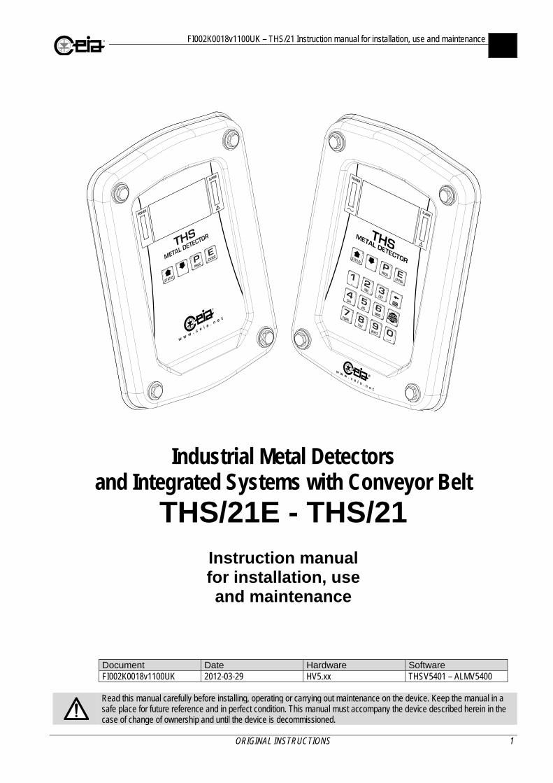
Industrial Metal Detectors and Integrated Systems with Conveyor Belt
THS/21E - THS/21
Instruction manual for installation, use and maintenance
Document Date Hardware Software FI002K0018v1100UK 2012-03-29 HV5.xx THSV5401 – ALMV5400
Read this manual carefully before installing, operating or carrying out maintenance on the device. Keep the manual in a safe place for future reference and in perfect condition. This manual must accompany the device described herein in the case of change of ownership and until the device is decommissioned.
FI002K0018v1100UK – THS/21 Instruction manual for installation, use and maintenance
2 ORIGINAL INSTRUCTIONS
SYMBOLS
The equipment is marked with this symbol wherever the user should refer to this manual in order to avoid possible damage. The same symbol appears in the manual at points where warnings or particularly important instructions, essential for safe, correct operation of the device, are given.
The equipment is marked with this symbol in the areas where there is dangerous voltage. Only trained maintenance personnel should carry out work in these areas. The same symbol appears in the manual at points where essential safety warnings are given.
The equipment is marked with this symbol in the areas where the user must be careful to avoid crushing of hands. Only trained maintenance personnel should carry out work in these areas. The same symbol appears in the manual at points where essential safety warnings are given.
The equipment is marked with this symbol in the areas where the user must be careful to avoid coming into contact with moving components. Only trained maintenance personnel should carry out work in these areas. The same symbol appears in the manual at points where essential safety warnings are given.
The equipment is marked with this symbol in the areas where the user must be careful to avoid crushing of feet. Only trained maintenance personnel should carry out work in these areas. The same symbol appears in the manual at points where essential safety warnings are given.
The equipment is marked with this symbol in the areas where there is the danger of unexpected bursts of compressed air. Only trained maintenance personnel should carry out work in these areas. The same symbol appears in the manual at points where essential safety warnings are given.
LASER LIGHT: This symbol appears in this manual at those points where warnings or information relating to laser pointing devices are given. Such devices may be dangerous. It is therefore essential that the guidelines in this manual be followed.
The equipment is marked with this symbol wherever the user must not have access to potentially dangerous areas.
CEIA Metal Detectors employ low intensity electromagnetic fields in compliance with current legislation. MAGNETIC FIELDS can affect pacemakers. Wearers of pacemakers, cardiac defibrillators and other life support devices must not operate in proximity of the inductor or the heating inductors of this device. Wearers of pacemakers must not use the Metal Detectors of the THS/MN21 series which use static electromagnetic fields. Wearers should consult their doctor for advice on avoiding this hazard.
This symbol appears in the manual at points where suggestions, additional information or other relevant notes are given.
REVISION HISTORY Rev. Date Author Reference Description 1000 2010-09-16 TP2 – SP - First issue for all THS/21E and THS/21 models
1100 2012-03-29 TP2 – SP
2.3.2, 2.8.2, 3.2.1, 3.2.3, 3.2.4, 3.3.3, 3.5.2.2, 4.5.6, 5, 5.6
Small corrections
1.2.2, 1.2.3, 1.2.4, 1.3.2, 1.4.2, 2.5.4, 2.9, 3.6.2.1, 3.6.7, 3.6.7.1, 3.6.8, 3.14, 4.4.1, 5.1
Management of external emergency buttons and other protections
2.8.2, 3.1.3, 4.5.6, 5.1 Additional indications on bins and respect for the environment
FI002K0018v1100UK – THS/21 Instruction manual for installation, use and maintenance
ORIGINAL INSTRUCTIONS 3
CONTENTS
1 SAFETY INSTRUCTIONS – WARNINGS ....... 8
1.1 Device users, required instruction level and training ............................................... 8
1.2 Warnings ................................................. 10
1.2.1 General warnings ..................................... 10
1.2.2 Installation warnings ................................. 10
1.2.3 Use warnings ............................................ 12
1.2.4 Maintenance warnings .............................. 14
1.3 Permitted uses. Improper uses. .............. 15
1.3.1 Permitted use ........................................... 15
1.3.2 Improper use ............................................ 15
1.4 Residual risks .......................................... 16
1.4.1 Installation ................................................ 16
1.4.2 Operating .................................................. 16
1.4.3 Maintenance ............................................. 16
2 DESCRIPTION ............................................... 17
2.1 General description ................................. 17
2.1.1 Detection probe ........................................ 17
2.1.2 Integrated conveyor .................................. 18
2.1.3 Products that can be inspected ................ 18
2.2 Detection Probes .................................... 19
2.2.1 THS/21E and THS/21E-3F ....................... 19
2.2.2 THS/21 and THS/MS21 ............................ 19
2.2.3 THS/MN21 ................................................ 20
2.2.4 THS/G21E ................................................ 21
2.2.5 THS/G21 and THS/GMS21 ...................... 21
2.2.6 Applicable power supply boxes ................ 22 2.2.6.1 Control Power Box (CPB) ................... 22 2.2.6.2 Remote Control Unit (RCU) ................ 23 2.2.6.3 Conveyor Control System (CCS) ........ 23 2.2.6.4 Field Generator ................................... 23 2.2.6.5 Small Size Power Supply Unit
(00211AL_ card) ................................. 23
2.3 Integrated system with conveyor belt ..... 24
2.3.1 Inverting component positions .................. 25 2.3.1.1 Inverting the antenna/PSU unit
position ............................................... 25 2.3.1.2 Inverting the ejection system position . 25
2.3.2 Models ...................................................... 26 2.3.2.1 THS/FBB (flat belt) .............................. 26 2.3.2.2 THS/FB (flat belt) ................................ 27 2.3.2.3 THS/MBB (modular belt) ..................... 28 2.3.2.4 THS/M65 and THS/M69K (modular
belt) ..................................................... 29 2.3.2.5 THS/MBR (modular belt) ..................... 30
2.4 Device identification ................................ 31
2.4.1 Probe ........................................................ 31
2.4.2 Control Power Box .................................... 31
2.4.3 Conveyor Control System ......................... 31
2.4.4 CEIA conveyor structure ........................... 32
2.5 Functional diagrams ............................... 33
2.5.1 THS with Control Power Box .................... 33
2.5.2 THS with Conveyor Control System ......... 33
2.5.3 Integrated systems ................................... 34
2.6 Dimensions ............................................. 35
2.6.1 Probes ...................................................... 35 2.6.1.1 THS/21, THS/MS21, THS/21E,
THS/21E-3F ....................................... 35 2.6.1.2 THS/SL21, THSSL21E ....................... 36 2.6.1.3 THS/MN21 .......................................... 36 2.6.1.4 THS/G21, THS/GMS21, THS/G21E ... 37
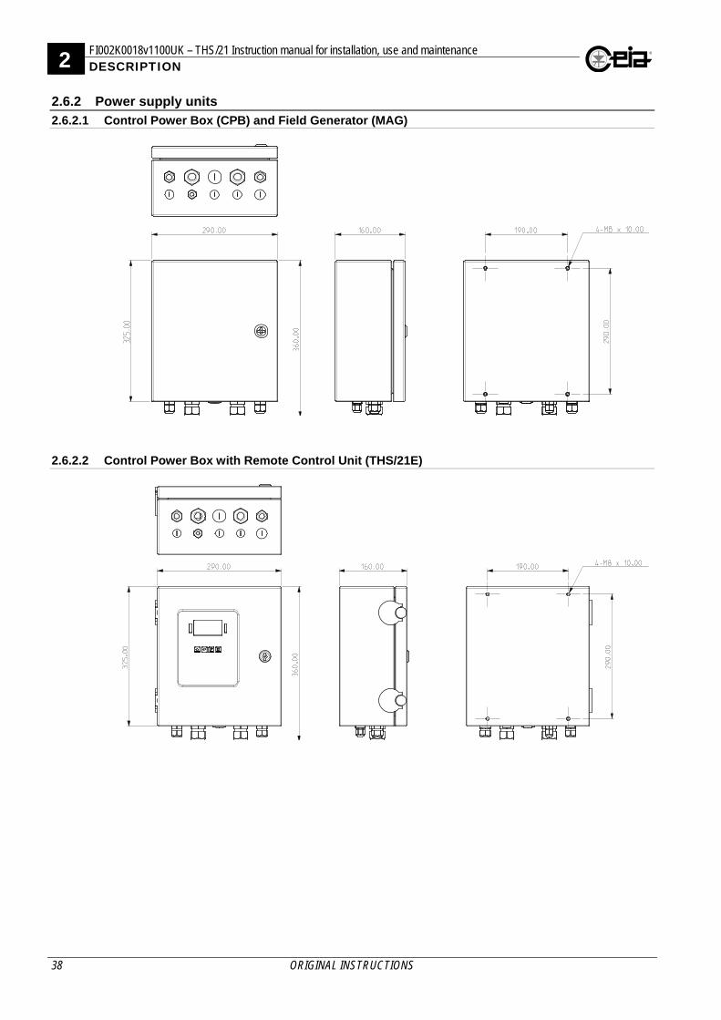
2.6.2 Power supply units ................................... 38 2.6.2.1 Control Power Box (CPB) and Field
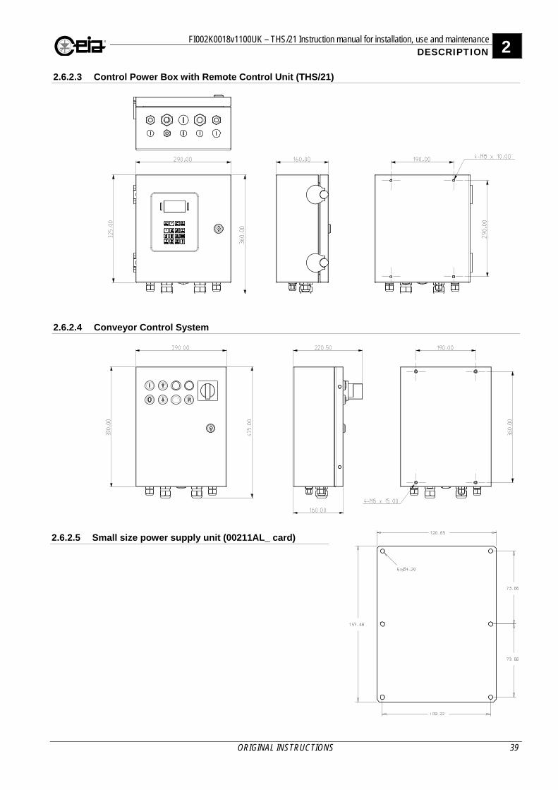
Generator (MAG) ................................ 38 2.6.2.2 Control Power Box with Remote
Control Unit (THS/21E) ....................... 38 2.6.2.3 Control Power Box with Remote
Control Unit (THS/21) ......................... 39 2.6.2.4 Conveyor Control System ................... 39 2.6.2.5 Small size power supply unit
(00211AL_ card) ................................. 39
2.6.3 Integrated systems ................................... 40 2.6.3.1 THS/FBB ............................................ 40 2.6.3.2 THS/FB ............................................... 40 2.6.3.3 THS/MBB ........................................... 41 2.6.3.4 THS/M65 and THS/M69K ................... 41 2.6.3.5 THS/MBR ........................................... 42
2.7 Options and Accessories ........................ 42
2.8 Technical characteristics ........................ 43
2.8.1 Metal Detector .......................................... 43
2.8.2 Integrated systems ................................... 45
2.9 Safety devices ........................................ 46
3 INSTALLATION ............................................. 47
3.1 General requirements ............................. 47
3.1.1 Minimum clearances ................................ 47 3.1.1.1 Probes ................................................ 47 3.1.1.2 Integrated systems ............................. 47
3.1.2 General installation guidelines for non-integrated models .................................... 48
3.1.2.1 Controls and Power Supply box ......... 48 3.1.2.2 Metal structures in proximity to the
probe .................................................. 49 3.1.2.3 Customer conveyor belt ...................... 51
3.1.3 Installation guidelines for correct environmental compatibility of the Metal Detector ................................................... 55
3.1.3.1 Power supply and control cables of other devices. ..................................... 55
3.1.3.2 Pulsed-type sources ........................... 55 3.1.3.3 Ground loops ...................................... 56 3.1.3.4 Conveyor belt motors ......................... 56 3.1.3.5 Selecting and installing connecting
cables ................................................. 57 3.1.3.6 Multiple Metal Detectors close
together .............................................. 57
3.2 Unpacking ............................................... 57
FI002K0018v1100UK – THS/21 Instruction manual for installation, use and maintenance
4 ORIGINAL INSTRUCTIONS
3.2.1 Metal Detector .......................................... 57 3.2.1.1 Handling and moving the packaged
device ................................................. 57 3.2.1.2 Unpacking procedure ......................... 58 3.2.1.3 Packing list ......................................... 58 3.2.1.4 Moving the Metal Detector .................. 59
3.2.2 CEIA Integrated Systems ......................... 59 3.2.2.1 Handling and moving the package
device ................................................. 59 3.2.2.2 Unpacking procedure ......................... 60 3.2.2.3 Packing list ......................................... 60 3.2.2.4 Moving the Metal Detector .................. 60
3.3 Mechanical installation ............................ 61
3.3.1 Probe ....................................................... 61
3.3.2 Integrated systems ................................... 62
3.3.3 Assembly of components ......................... 62 3.3.3.1 Metal Detector .................................... 62 3.3.3.2 Integrated systems ............................. 62
3.4 Pneumatic installation ............................. 63
3.4.1 Minimum requirements ............................. 63
3.4.2 Pneumatic circuit diagrams ...................... 63 3.4.2.1 Ejector cylinder or retracting belt ........ 63 3.4.2.2 Air jet ejection system ......................... 63
3.4.3 Connecting up to the compressed air supply ....................................................... 64
3.4.3.1 Ejector cylinder or retracting belt ........ 64 3.4.3.2 Air jet ejector ...................................... 64
3.4.4 Adjustment ............................................... 64 3.4.4.1 Ejector cylinder or retracting belt ........ 64 3.4.4.2 Air jet ejector ...................................... 64
3.4.5 Padlocking the compressed air ................ 64
3.5 Electrical Installation ............................... 64
3.5.1 Installing connecting cables ..................... 64
3.5.2 Description of inputs ................................. 65
3.5.3 Description of outputs .............................. 66
3.5.4 Description of I/O interfaces ..................... 67
3.5.5 Communication connections .................... 67 3.5.5.1 RS232 serial port connections ............ 67 3.5.5.2 Bluetooth communication ................... 67 3.5.5.3 Ethernet / WiFi connections (on
request, with IXC card) ....................... 67
3.5.6 Connection to the Production Line emergency circuit ..................................... 68
3.5.7 Connecting a motor (Conveyor Control System only) ............................................ 69
3.5.8 Connecting to the mains power supply .... 70 3.5.8.1 Connection to earth ............................ 70 3.5.8.2 Power Switch ...................................... 71
3.6 Electrical diagrams .................................. 72
3.6.1 Functional diagrams ................................. 72 3.6.1.1 Control Power Box .............................. 72 3.6.1.2 Conveyor Control System ................... 72
3.6.2 Control Power Box ................................... 73 3.6.2.1 ALM card ............................................ 73 3.6.2.2 Small Size Power Supply – ALM
card .................................................... 75
3.6.2.3 Field Generator (MAG) for THS/MN21 .......................................... 76
3.6.2.4 Conveyor Control System – ALM card ..................................................... 78
3.6.3 SCD card .................................................. 82 3.6.3.1 THS/xx21E .......................................... 82 3.6.3.2 THS/xx21E-3F .................................... 82 3.6.3.3 THS/xx21 ............................................ 83 3.6.3.4 THS/xxMS21 ....................................... 83 3.6.3.5 THS/MN21 .......................................... 84
3.6.4 IXC card (available on request) ................ 85
3.6.5 Integrated Systems ................................... 86 3.6.5.1 THS/FBB and THS/MBB ..................... 86 3.6.5.2 THS/FBB and THS/MBB with Bin full
and Low pressure sensors .................. 88 3.6.5.3 THS/FB, THS/MBR, THS/M65 and
THS/M69K .......................................... 90
3.7 Connections to other devices ................. 92
3.7.1 00211ALM card ........................................ 92
3.7.2 00211AL_ card ......................................... 95
3.7.3 Connection of push-buttons or sensors .... 97 3.7.3.1 Sensor positioning .............................. 98
3.7.4 Connection of an ejector ........................... 98
3.7.5 Synchronization photocell ......................... 99
3.7.6 Connection to other in-line devices or machines .................................................. 99
3.8 Configuration ........................................ 100
3.8.1 System start-up ...................................... 100
3.8.2 Preliminary settings ................................ 100
3.8.3 Checking the input and output connections ............................................ 100
3.8.4 Motor (only with Conveyor Control System) .................................................. 101
3.8.5 Transit speed .......................................... 102 3.8.5.1 Application with Control Power Box .. 102 3.8.5.2 Application with Conveyor Control
System .............................................. 102
3.8.6 Encoder .................................................. 103
3.8.7 Synchronization photocell ....................... 103
3.8.8 Ejection check photocell ......................... 104
3.8.9 Ejection mode ......................................... 105 3.8.9.1 Transport stop with manual reset
(EM=B) .............................................. 105 3.8.9.2 Belt stop with photocell
synchronization and manual reset (EM=SB) ........................................... 106
3.8.9.3 Reversing belt (EM=R) ...................... 107 3.8.9.4 Automatic ejection with alarm
synchronization (EM=F) .................... 108 3.8.9.5 Automatic ejection with photocell
synchronization (EM=S) .................... 109 3.8.9.6 Automatic ejection with photocell
synchronization (EM=FS) .................. 110
3.8.10 Barcode reader ....................................... 111 3.8.10.1 With change of Detection Mode or
Band between two products .............. 111 3.8.10.2 Without change of Detection Mode or
Band between two products .............. 111
3.9 Timing ................................................... 112

FI002K0018v1100UK – THS/21 Instruction manual for installation, use and maintenance
ORIGINAL INSTRUCTIONS 5
3.9.1 Belt stop (EM=B) .................................... 112
3.9.2 Belt stop with photocell synchronization (EM=SB) ................................................. 113
3.9.3 Reversing belts (EM=R) ......................... 114
3.9.4 Automatic ejection with alarm synchronization (EM=F) ......................... 114
3.9.5 Automatic ejection with photocell synchronization (EM=S) ......................... 115
3.9.6 Automatic ejection with photocell synchronization (EM=FS) ....................... 116
3.10 Enabling from and to external machines117
3.10.1 Metal Detector inhibition ......................... 117
3.10.2 Enabling the upstream conveyor belt ..... 117
3.10.3 Enabling from the downstream belt ........ 118 3.10.3.1 Gravity fall applications ..................... 118
3.11 Checking the correct installation and configuration ......................................... 119
4 USE OF THE DEVICE .................................. 120
4.1 Indicators .............................................. 120
4.1.1 Optical indicators .................................... 120 4.1.1.1 Control panel .................................... 120 4.1.1.2 Conveyor Control System ................. 120 4.1.1.3 External beacon ................................ 121
4.1.2 Acoustic indicators .................................. 121
4.2 Controls ................................................. 122
4.2.1 Control Panel .......................................... 122
4.2.2 Conveyor Control System power supply unit control panel .................................... 123
4.3 Programming access ............................ 124
4.4 Switching on the Metal Detector ........... 125
4.4.1 Checking the safety features .................. 125 4.4.1.1 Checking emergency buttons ........... 126
4.4.2 Switching on ........................................... 126
4.4.3 Signals at power-up ................................ 126
4.4.4 Signals given during normal operation ... 127 4.4.4.1 Indication of the received signal ........ 127 4.4.4.2 Display messages ............................. 128
4.4.5 Signals given during self-diagnosis ........ 128
4.5 Use of the device .................................. 129
4.5.1 Sensitivity check with reference sample . 129
4.5.2 Starting/stopping the conveyor belt ........ 129
4.5.3 Adjustment of the belt speed .................. 129
4.5.4 Alarm reset ............................................. 130
4.5.5 Fault reset .............................................. 130
4.5.6 Removing and emptying the reject bin ... 131 4.5.6.1 THS/FBB and THS/MBB ................... 131 4.5.6.2 THS/FB and THS/M69K .................... 131 4.5.6.3 THS/MBR .......................................... 132
4.5.7 Automatic stop ........................................ 133
4.6 Programming ........................................ 133
4.7 Programming the Metal Detector according to the product type ............... 133
4.8 Sensitivity check with reference sample 134
4.8.1 Programming the request frequency of the periodic tests .....................................134
4.8.2 Performing tests ......................................134 4.8.2.1 Test procedure ..................................135
4.8.3 Quick test ................................................137
4.9 Settings for CFR21 Standards ............. 138
4.9.1 General information.................................138
4.9.2 Metal Detector settings ...........................138
5 MAINTENANCE ........................................... 139
5.1 Periodic Maintenance ........................... 139
5.2 Periodic Maintenance procedures ........ 139
5.2.1 External cleaning instructions .................139
5.2.2 Parts in contact with the product .............140
5.2.3 Cleaning the Conveyor belt .....................141 5.2.3.1 Ejection system .................................141 5.2.3.2 Belt disassembly ...............................142
5.2.4 Conveyor belt tension adjustment ...........144 5.2.4.1 THS/FBB and THS/FB .......................144
5.3 Troubleshooting .................................... 145
5.4 Extraordinary maintenance procedures 147
5.4.1 Changing fuses .......................................147
5.4.2 Replacing the SCD card ..........................148
5.5 Compatibility check procedures............ 150
5.5.1 General compatibility check ....................150
5.5.2 Electrical Compatibility check ..................150
5.5.3 Checking belt contamination ...................151
5.5.4 General or electrical compatibility checks result ...........................................151
5.6 Self-diagnosis ....................................... 152
5.7 Uninstallation procedure ....................... 158
5.7.1 Disassembly ............................................158
5.7.2 Packing ...................................................158 5.7.2.1 Probes ...............................................158 5.7.2.2 Integrated systems ............................159
5.8 Disposal of the device .......................... 160
5.8.1 Disposal of the device and of consumables with environmental impact .160
6 APPENDICES .............................................. 161
6.1 CE Declaration of Conformity ............... 161
6.1.1 THS/21, THS/G21, THS/SL21, THSMN21, THS/MS21 ............................161
6.1.2 THS/FB, THS/FBB, THS/M69K, THS/MBB and THS/MBR ........................162
6.2 Spare Parts ........................................... 162

FI002K0018v1100UK – THS/21 Instruction manual for installation, use and maintenance
6 ORIGINAL INSTRUCTIONS
Warranty terms
The warranty period on all CEIA products is 12 months from the date of delivery. The warranty applies to all products supplied by us. The warranty covers defects of all components excluding batteries. The warranty does not cover damage caused by improper or inappropriate use or use for purposes other than those described in this manual. Do not tamper with the device. Do not open the housing. Tampering with or opening the device will void the warranty.
Customer Satisfaction Report
Your suggestions and comments on the products and services offered by CEIA and its
distribution network are extremely important for improving our procedures. Please send them to us by completing and returning the form available at:
http://www.ceia.net/industrial/satisfaction
Thank you for your kind interest and co-operation.

FI002K0018v1100UK – THS/21 Instruction manual for installation, use and maintenance
ORIGINAL INSTRUCTIONS 7
Preface
This document is the property of CEIA S.p.A. which reserves all rights. Total or partial copying, modification and translation is forbidden. CEIA reserves the right to make changes, at any time and without notice, to the models (including programming), their accessories and options, and to the prices and conditions of sale. The Metal Detector or the CEIA integrated system must be used only for the prescribed purpose and in the ways described in this Manual. CEIA may not be held responsible for the consequences resulting from a use other than that indicated in this Manual.
Purpose of the documentation
The complete documentation for a CEIA Metal Detector is made up of a series of Manuals, whose purposes are listed in the following paragraphs:
Installation, Use and Maintenance Manual
The purpose of the Installation, Use and Maintenance Manual is to provide the information needed for:
- installing the Metal Detector or CEIA integrated system, according to the electrical and mechanical requirements specified by CEIA;
- configuring the Metal Detector in accordance with the type of installation and use;
- correct use of the conveyor belt system;
- correct maintenance, both ordinary and extraordinary.
Programming Manual
The purpose of the Programming Manual is to provide a description of all the items of the System Programming Menu to:
- define the users authorized to operate the System;
- programme the Metal Detector in accordance with the type of product to be inspected;
- make remote connections with the Metal Detector, using the available communication interfaces.
Operator Manual
The purpose of the Operator Manual is to provide all the information needed by the operator for daily use of the system.
Options, Accessories and Spare Parts List
The purpose of this document is to provide a quick consultation table for ordering any spare parts, options and accessories.
1 FI002K0018v1100UK – THS/21 Instruction manual for installation, use and maintenance SAFETY INSTRUCTIONS - WARNINGS
8 ORIGINAL INSTRUCTIONS
Read this manual carefully before installing or operating the device and before carrying out maintenance operations.
1 SAFETY INSTRUCTIONS – WARNINGS
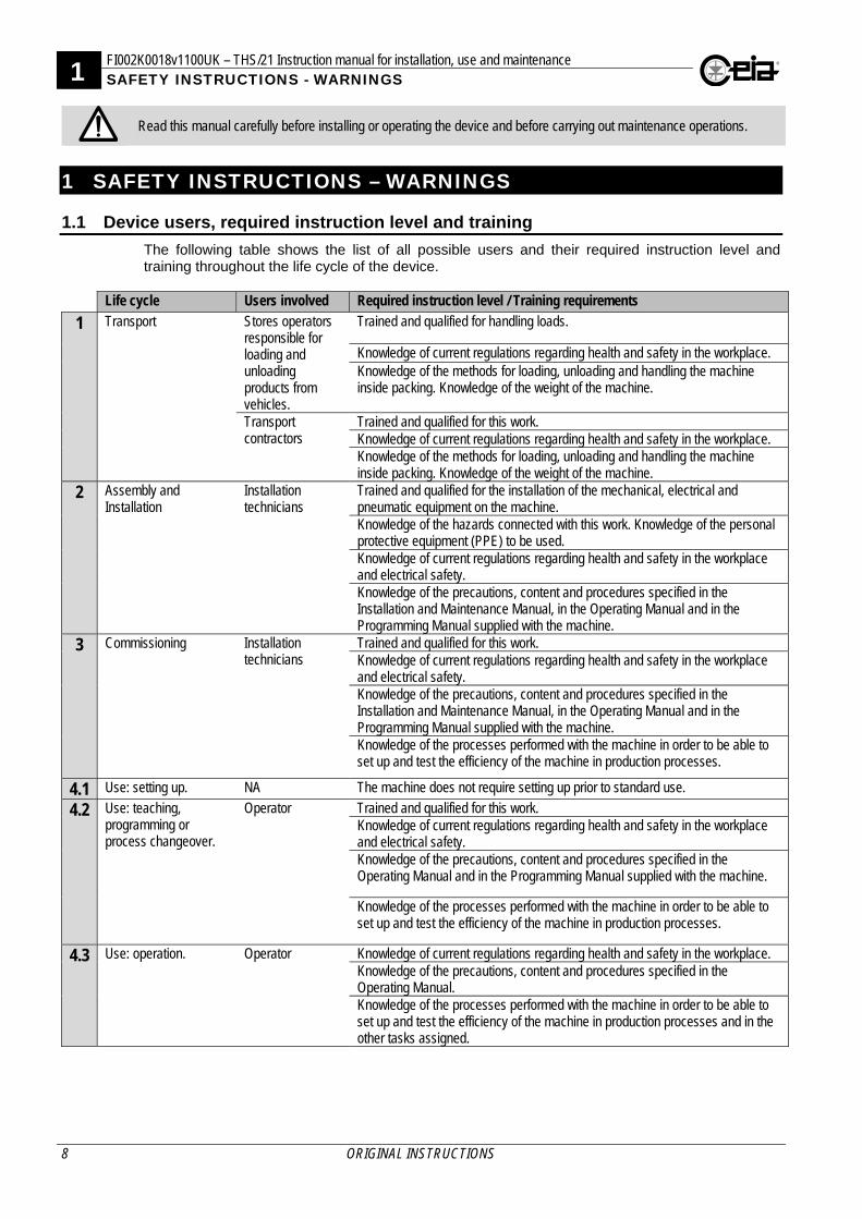
1.1 Device users, required instruction level and training
The following table shows the list of all possible users and their required instruction level and training throughout the life cycle of the device.
Life cycle Users involved Required instruction level / Training requirements
1 Transport Stores operators responsible for loading and unloading products from vehicles.
Trained and qualified for handling loads.
Knowledge of current regulations regarding health and safety in the workplace. Knowledge of the methods for loading, unloading and handling the machine inside packing. Knowledge of the weight of the machine.
Transport contractors
Trained and qualified for this work. Knowledge of current regulations regarding health and safety in the workplace. Knowledge of the methods for loading, unloading and handling the machine inside packing. Knowledge of the weight of the machine.
2 Assembly and Installation
Installation technicians
Trained and qualified for the installation of the mechanical, electrical and pneumatic equipment on the machine. Knowledge of the hazards connected with this work. Knowledge of the personal protective equipment (PPE) to be used. Knowledge of current regulations regarding health and safety in the workplace and electrical safety. Knowledge of the precautions, content and procedures specified in the Installation and Maintenance Manual, in the Operating Manual and in the Programming Manual supplied with the machine.
3 Commissioning Installation technicians
Trained and qualified for this work. Knowledge of current regulations regarding health and safety in the workplace and electrical safety. Knowledge of the precautions, content and procedures specified in the Installation and Maintenance Manual, in the Operating Manual and in the Programming Manual supplied with the machine. Knowledge of the processes performed with the machine in order to be able to set up and test the efficiency of the machine in production processes.
4.1 Use: setting up. NA The machine does not require setting up prior to standard use.
4.2 Use: teaching, programming or process changeover.
Operator Trained and qualified for this work. Knowledge of current regulations regarding health and safety in the workplace and electrical safety. Knowledge of the precautions, content and procedures specified in the Operating Manual and in the Programming Manual supplied with the machine.
Knowledge of the processes performed with the machine in order to be able to set up and test the efficiency of the machine in production processes.
4.3 Use: operation. Operator Knowledge of current regulations regarding health and safety in the workplace. Knowledge of the precautions, content and procedures specified in the Operating Manual. Knowledge of the processes performed with the machine in order to be able to set up and test the efficiency of the machine in production processes and in the other tasks assigned.
FI002K0018v1100UK – THS/21 Instruction manual for installation, use and maintenance 1 SAFETY INSTRUCTIONS - WARNINGS
ORIGINAL INSTRUCTIONS 9
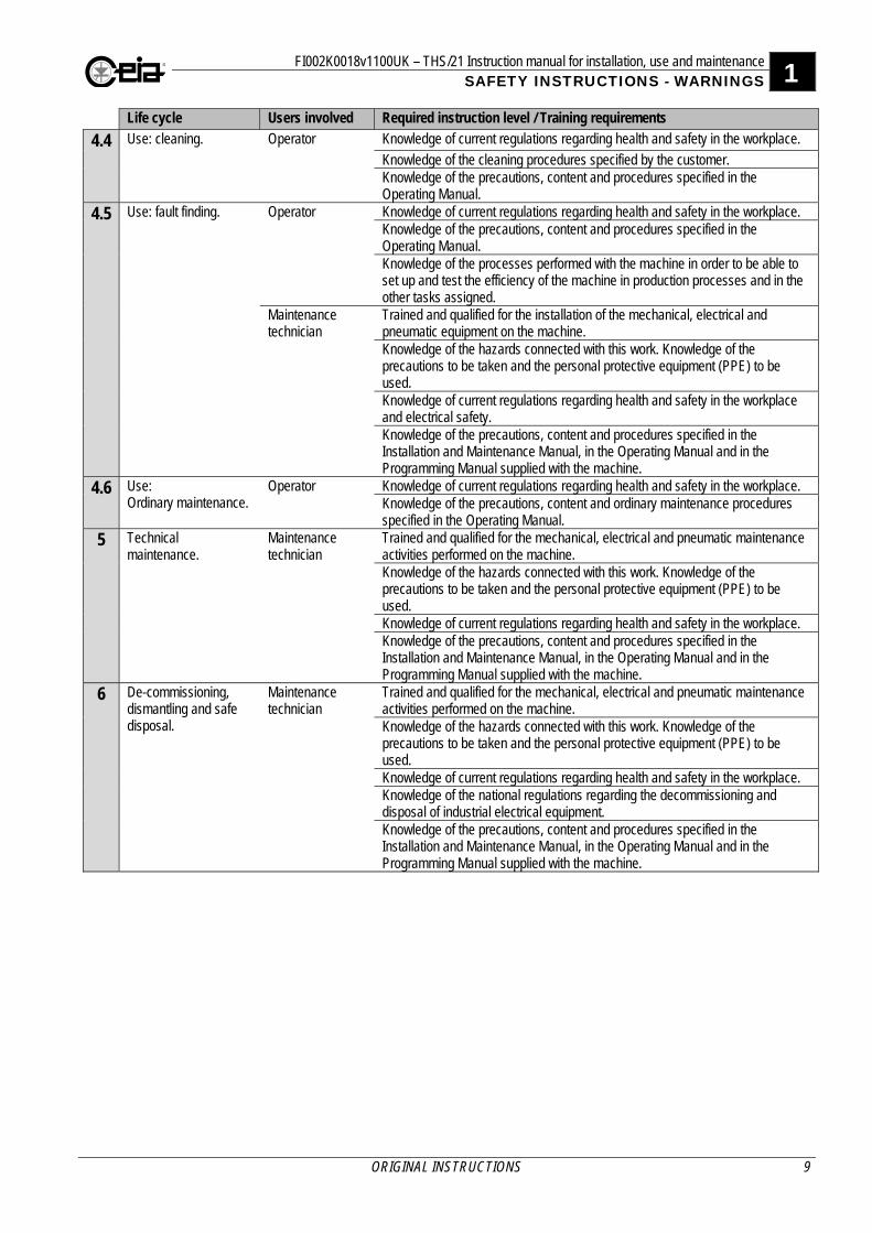
Life cycle Users involved Required instruction level / Training requirements
4.4 Use: cleaning. Operator Knowledge of current regulations regarding health and safety in the workplace. Knowledge of the cleaning procedures specified by the customer. Knowledge of the precautions, content and procedures specified in the Operating Manual.
4.5 Use: fault finding. Operator Knowledge of current regulations regarding health and safety in the workplace. Knowledge of the precautions, content and procedures specified in the Operating Manual. Knowledge of the processes performed with the machine in order to be able to set up and test the efficiency of the machine in production processes and in the other tasks assigned.
Maintenance technician
Trained and qualified for the installation of the mechanical, electrical and pneumatic equipment on the machine. Knowledge of the hazards connected with this work. Knowledge of the precautions to be taken and the personal protective equipment (PPE) to be used. Knowledge of current regulations regarding health and safety in the workplace and electrical safety. Knowledge of the precautions, content and procedures specified in the Installation and Maintenance Manual, in the Operating Manual and in the Programming Manual supplied with the machine.
4.6 Use: Ordinary maintenance.
Operator Knowledge of current regulations regarding health and safety in the workplace. Knowledge of the precautions, content and ordinary maintenance procedures specified in the Operating Manual.
5 Technical maintenance.
Maintenance technician
Trained and qualified for the mechanical, electrical and pneumatic maintenance activities performed on the machine. Knowledge of the hazards connected with this work. Knowledge of the precautions to be taken and the personal protective equipment (PPE) to be used. Knowledge of current regulations regarding health and safety in the workplace. Knowledge of the precautions, content and procedures specified in the Installation and Maintenance Manual, in the Operating Manual and in the Programming Manual supplied with the machine.
6 De-commissioning, dismantling and safe disposal.
Maintenance technician
Trained and qualified for the mechanical, electrical and pneumatic maintenance activities performed on the machine. Knowledge of the hazards connected with this work. Knowledge of the precautions to be taken and the personal protective equipment (PPE) to be used. Knowledge of current regulations regarding health and safety in the workplace. Knowledge of the national regulations regarding the decommissioning and disposal of industrial electrical equipment. Knowledge of the precautions, content and procedures specified in the Installation and Maintenance Manual, in the Operating Manual and in the Programming Manual supplied with the machine.
1 FI002K0018v1100UK – THS/21 Instruction manual for installation, use and maintenance SAFETY INSTRUCTIONS - WARNINGS
10 ORIGINAL INSTRUCTIONS
1.2 Warnings
1.2.1 General warnings - Failure to comply with one or more of the instructions in this Manual increases the risk of an
incident. Follow ALL the instructions in this Manual.
- All personnel operating with or performing operations on the device must have adequate preparation and must know the procedures and warnings described in this manual.
- Observe current regulations regarding electrical and personal safety for both the operator and the installer when installing the device.
- Any modification to the configuration set up by CEIA is forbidden and will void all warranties and certifications.
- Follow the instructions contained in this manual for all operations relating to installation, use and maintenance of the device. CEIA declines all liability for damage caused by failure to follow the instructions in this manual or for damage caused by non-permitted use, improper use or negligence.
- This manual must accompany the device described herein in the case of change of ownership and until the device is decommissioned.
- Before you move the detector, check its weight. It could be too heavy to be handled by one person. Use suitable handling methods and tools. CEIA may not be held responsible for injury to persons or damage to property resulting from not following a procedure.
- On integrated systems fitted with castors, lock the castors to prevent accidental movement.
1.2.2 Installation warnings
Observe current regulations regarding electrical and personal safety for both the operator and the installer when installing the device.
- If a CEIA integrated system is installed within a production line, the purchaser is responsible for commissioning the machine only after the entire production line has been verified as compliant.
- If a CEIA integrated system with an ejection system is used and is not installed within a production line, at the exit of the belt a further unloading belt needs to be provided at the belt exit, with a fixed guard to prevent operators accessing the ejection area with their hands or limbs. The distance from the ejector must comply with table 1 of UNI EN 13857. The guard can also be purchased from CEIA.
- The equipment must be installed in well-lit surroundings (minimum average 500 LUX maintained) where there is no need for additional lighting. Natural light, where sufficient, is enough to illuminate the parts to be inspected.
- The equipment must be installed in a position where there is sufficient space for the operator to work in complete safety.
- Make all electrical connections following the procedures described in the Installation section of this manual.
- If the CEIA integrated system is connected in line with other machines, the emergency buttons must be connected in such a way that activating one emergency button on the line stops all the machines on that line.
- In integrated systems with ejection system and reject bin, the frequency of emptying the bin must be assessed: if this frequency is more than once a shift, the "Activation of emergency with bin absent" option must be installed.
- Position the device as far away as possible from sources of electromagnetic interference, such as transformers or motors.
- This device contains electrical and electronic components and may therefore be susceptible to fire. Do not install in potentially explosive atmospheres or in contact with inflammable material. Do not use water or foam in the case of fire when the device is powered up.
- The power supply to the equipment must be fitted with a main ON-OFF switch which completely shuts down the power supply to the equipment. Unless otherwise specified, before you start maintenance on the machine you should switch off and lock out the power supply at this switch.
- Only make the connections to the internal terminals of the power supply unit when the unit is disconnected from the mains.
FI002K0018v1100UK – THS/21 Instruction manual for installation, use and maintenance 1 SAFETY INSTRUCTIONS - WARNINGS
ORIGINAL INSTRUCTIONS 11
- Only connect up the compressed air supply after you have completed installation of the device and made all the other connections.
- Before connecting the device to the power supply, ensure that the power supply voltage corresponds to that indicated on the rating plate attached to the device. Checking that the power supply conforms to the values specified on the rating plate and to the regulations in force is the responsibility of the customer.
- The power supply must be fitted with an earth/ground connection. Any break in the safety conductor, either inside or outside the device, or disconnection of the earth/ground safety terminal, will render the device dangerous. Intentional cutting or disconnection is strictly forbidden.
- The device should be connected to the mains power supply only after all connections required for full installation have been completed.
- To avoid damage due to lightning, fit the power supply line with appropriate surge suppressors.
- The installation and handling of systems with wheels is allowed only on level floors.
- After installation the device should be stable and not subject to vibration or accidental movement. On systems with castors, the castors should be locked. On systems with feet, these must be anchored to the floor. All connecting cables should be properly fastened down, in order to avoid knocks and accidental damage and to ensure optimum performance.
- Once the electrical connections have been completed, seal the unused cable glands to stop water or other foreign bodies entering the power supply unit.
- There are dangerous voltages inside the power supply unit. Close the cover and keep the key safe so that it is only available for use by authorized, trained personnel (EN 60204 standard).
- During installation take precautions to protect the detector opening or inside surface from damage. Do not use the opening for lifting.
- When you have completed installation, check the area around the machine for safety hazards. Check that there is sufficient space for the operator to work with the equipment.
- Installation and additional final testing is the responsibility of the final user.

1 FI002K0018v1100UK – THS/21 Instruction manual for installation, use and maintenance SAFETY INSTRUCTIONS - WARNINGS
12 ORIGINAL INSTRUCTIONS
1.2.3 Use warnings
CEIA Metal Detectors employ low intensity electromagnetic fields in compliance with current legislation. MAGNETIC FIELDS can affect pacemakers. Wearers of pacemakers, cardiac defibrillators and other life support devices must not operate in proximity of the inductor or the heating inductors of this device. Wearers of pacemakers must not use the Metal Detectors of the THS/MN21 series which use static electromagnetic fields. Wearers should consult their doctor for advice on avoiding this hazard.
- If the device is stored for a long period in temperatures outside the operating range, wait for the temperature of the detector to come back within that range before switching on.
- Do not supply the device when the Power Supply Box is open.
- Trapping and drawing in hazard. Do not place body parts, clothing or dangling objects close to the device. Do not wear loose fitting clothing which might become trapped in the machine. If you have long hair, wear a hair net. Do not wear protruding or hanging items, such as bracelets, ties, necklaces, scarves, etc.
- During use do not insert body parts or objects inside the material transit tunnel.
- Do not obstruct product transit.
- When the machine is operating, only use the control panels and the emergency stop buttons to control the machine.
- Before you start the conveyor belt, check that the reject bin and its cover are present and correctly positioned.
- Before you make any changes to the machine configuration, switch off the machine. Changes to machine configuration may only be made by authorized personnel who have control of the work area.
- Whenever there is any suggestion that the level of protection has been reduced, the device should be taken out of service and secured against accidental start-up. Call an authorized service technician for assistance. The level of protection is considered to have been reduced when:
- the device shows visible signs of wear and tear, especially on parts that ensure the device protections (boxes, gaskets, glands, fixing screws, etc.);
- the power supply box is not correctly closed;
- the earth/ground connections are not compliant;
- the device has suffered mechanical or electrical damage (knocks, shocks, bumps, etc.);
- the device does not operate correctly or as specified in this manual;
- the device has been stored for long periods in sub-optimal conditions;
- the device has suffered severe stress during transport;
- the device has come into contact with corrosive substances. - Empty the reject bin at regular intervals. Exercise caution when emptying the bin because it
could be heavy or contain very hot material. Define and implement a procedure for this operation. CEIA declines all liability for injury to persons or damage to property caused by incorrect emptying of the reject bin.
- The absence of a reject bin or a system for collecting ejected product can cause material to be deposited on the floor thereby creating a tripping and slipping hazard.
- Hard knocks to parts of the compressed air system can cause damage leading to leaks, bursting or the escape of compressed air.
- The machine is not fitted with a safety valve which depressurizes the compressed air system in the event of a power failure that causes the lighting to fail. Automatic ejection systems (pusher cylinder or air jet types) will be powered down in the event of a power failure.
- In some models, the drive motor of the conveyor belt is covered by a metal guard except on the lower side and on the side facing the inside of the machine. Burns hazard: guard surfaces are very hot.
- Burns hazard. Caution hot surfaces. If the weight carried on the belt exceeds the limits specified in the technical data this will cause the motor to overheat. If dirt residues are not cleaned from the machine at regular intervals this will also cause the motor to overheat.
- Although the power of the laser beam used in barcode readers is very low, it can be dangerous to the human eye if stared into for long periods of time.

FI002K0018v1100UK – THS/21 Instruction manual for installation, use and maintenance 1 SAFETY INSTRUCTIONS - WARNINGS
ORIGINAL INSTRUCTIONS 13
- Failure to follow the operating instructions in this manual may cause a loss of food characteristics.
- On equipment where the material to be inspected is loaded and unloaded manually, it is the customer’s responsibility to assess the risks to operator health and safety.
- On integrated systems with the Following Conveyor connected up, the belt may start and stop unexpectedly because it is controlled from this infeed line.
- If the system is fitted with wheels, these must be locked. All the connection cables must be suitably fastened, in order to avoid accidental impacts or injury or risks for the operators and achieve the best operation of the device.
- The vibration risk to the hand-arm system is not applicable.

1 FI002K0018v1100UK – THS/21 Instruction manual for installation, use and maintenance SAFETY INSTRUCTIONS - WARNINGS
14 ORIGINAL INSTRUCTIONS
1.2.4 Maintenance warnings - During all maintenance operations ensure the complete absence of any potentially explosive
atmosphere. - Perform all maintenance operations following the procedures described in the Maintenance
section of this manual.
- Before you move the machine or start maintenance or cleaning, switch off and lock out the power supply and the compressed air supply.
- Before performing any maintenance or cleaning operation or moving the equipment, switch the electrical and pneumatic disconnectors to the OFF position, fitting a padlock. See the Installation section for the procedure.
- All the system containers have a protection class that protects them from dust and water penetrating inside them. Do not open doors if there is dust or water in the atmosphere, to prevent them getting in.
- Ensure that replacement fuses are of the correct rating and of the prescribed type. Makeshift fuses and short-circuiting of the fuse boards are strictly forbidden.
- Clean the various parts of the system following the procedures defined by the customer. Cleaning procedures should also comply with the hygiene requirements for the process and the working environment and must also take into account the degree of protection of the equipment.
- The machines are designed for use with a large range of food products and in a wide variety of production environments. This makes it difficult for us to specify a sanitizing procedure for all applications. It is the final user’s responsibility to draft suitable sanitizing procedures for their applications. The final user should also ensure that the instructions do not involve the use of methods or substances which are incompatible with the machine characteristics specified in the manual.
- Read the chapter on Maintenance carefully before calling the service centre. Whatever the problem, only specialized service personnel authorized to work with CEIA equipment should be called.
- Any damaged parts of the device should be substituted with original components only.
- Any maintenance or repair of the device while open and powered up should be avoided and in any case should only be carried out by trained personnel who are fully aware of the risks which the operation entails, following the instructions given in the Maintenance section.
- Before you restart the machine, check that all the guards are present and efficient. Check that the drive components and the electrical and pneumatic systems are efficient.
- Disposal of parts with environmental impact: follow the regulations in force in the country where the device is being used (refer to the Maintenance section).
FI002K0018v1100UK – THS/21 Instruction manual for installation, use and maintenance 1 SAFETY INSTRUCTIONS - WARNINGS
ORIGINAL INSTRUCTIONS 15
1.3 Permitted uses. Improper uses.
1.3.1 Permitted use - The THS/21E and THS/21 electronic Metal Detectors are designed for the detection of
magnetic and non-magnetic metal masses transiting inside the detection probe.
- Handle the device with care and without excessive force during installation, use and maintenance.
- The final user is responsible for selecting the appropriate sensitivity for their application. After this selection has been made, and programming has been adjusted accordingly, it is also the final user's responsibility to check calibration using the test object(s) appropriate to the level of security selected. Calibration testing must also be performed at regular intervals to ensure the continued efficiency of the equipment.
1.3.2 Improper use - The THS/21E and THS/21 Metal Detectors are not suitable for installation or use in explosive
or potentially explosive atmospheres.
- Any installation, use and maintenance operation other than the procedures in this manual is forbidden.
- Any maintenance or repair of the device while open and powered up should be avoided, and in any case should only be carried out by trained personnel who are fully aware of the risks which the operation entails.
- It is forbidden to use CEIA integrated systems if there is no bin to collect rejected material.
- Electric arc welding must not be carried out on the detector probe, on the control power box, on the conveyor belt or on any part of the attached structure.
- The device is fitted with mechanical and electronic protections, described in this manual. Removing or reducing these protections is forbidden.
- The machine is not designed for use in hazardous environments where there is a risk to the health and safety of the operator.
- It is forbidden to use the equipment in very dry environments. Very dry environments can generate electrostatic charges.
1 FI002K0018v1100UK – THS/21 Instruction manual for installation, use and maintenance SAFETY INSTRUCTIONS - WARNINGS
16 ORIGINAL INSTRUCTIONS
1.4 Residual risks
1.4.1 Installation - Exercise extreme caution when connecting up electrical components and the earth. Incorrect
connections can create an electrocution hazard.
- Do not exceed the compressed air pressure rating. Exceeding this rating can cause an overpressure and explosion hazard.
- Tipping hazard. On integrated systems failure to follow the instructions given in this manual may cause the machine to tip over.
1.4.2 Operating
CEIA Metal Detectors employ low intensity electromagnetic fields in compliance with current legislation. MAGNETIC FIELDS can affect pacemakers. Wearers of pacemakers, cardiac defibrillators and other life support devices shall not operate in proximity of the inductor or the heating inductors of this device. Wearers of pacemakers must not use the Metal Detectors of the THS/MN21 series which use static electromagnetic fields. Wearers should consult their doctor for advice on avoiding this hazard.
- Trapping and drawing in hazard. Body parts or loose dangling clothing can become trapped in the moving parts of the machine. Only authorized operators wearing suitably close-fitting overalls are permitted to work in this area. In MB and MBB type belts this risk is greater as the modular belt is in an accessible position during normal operations by the operator.
- Injury hazard to eyes, ears and sensitive body parts. When operating the machine do not approach the depressurizing pipe of the blower ejector.
1.4.3 Maintenance
- Systems with a conveyor belt. Before you restart the motor after maintenance, make sure that no screwdrivers, tools or other objects have been left on the belt. Objects left on the belt will be thrown outwards when the system is started.
FI002K0018v1100UK – THS/21 Instruction manual for installation, use and maintenance 2 DESCRIPTION
ORIGINAL INSTRUCTIONS 17
2 DESCRIPTION 2.1 General description
CEIA THS inspection systems detect metals with high detection sensitivity, for industrial use in inspecting food or other compatible products (see paragraph 2.1.3). They are available in two versions: - Detection antenna with power supply unit
- Detection antenna with integrated conveyor belt system
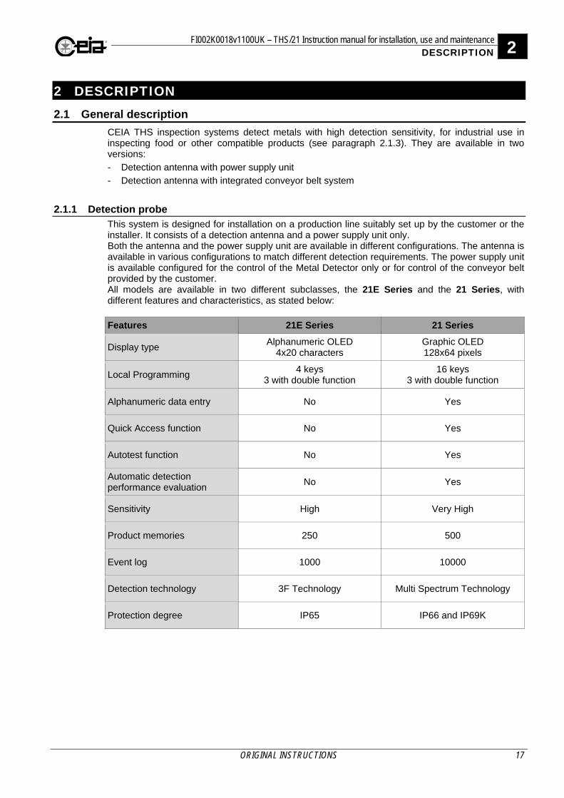
2.1.1 Detection probe This system is designed for installation on a production line suitably set up by the customer or the installer. It consists of a detection antenna and a power supply unit only. Both the antenna and the power supply unit are available in different configurations. The antenna is available in various configurations to match different detection requirements. The power supply unit is available configured for the control of the Metal Detector only or for control of the conveyor belt provided by the customer. All models are available in two different subclasses, the 21E Series and the 21 Series, with different features and characteristics, as stated below:
Features 21E Series 21 Series
Display type Alphanumeric OLED
4x20 characters Graphic OLED 128x64 pixels
Local Programming 4 keys
3 with double function 16 keys
3 with double function
Alphanumeric data entry No Yes
Quick Access function No Yes
Autotest function No Yes
Automatic detection performance evaluation
No Yes
Sensitivity High Very High
Product memories 250 500
Event log 1000 10000
Detection technology 3F Technology Multi Spectrum Technology
Protection degree IP65 IP66 and IP69K
2 FI002K0018v1100UK – THS/21 Instruction manual for installation, use and maintenance DESCRIPTION
18 ORIGINAL INSTRUCTIONS
2.1.2 Integrated conveyor With this version the CEIA THS Metal Detector is fully housed in a high-hygiene, stainless steel structure fitted with a digital controller for controlling speed and the ejection stages for non-conforming product. CEIA inspections systems are available in a wide range of sizes suitable for a wide variety of applications. The casing structure, the Metal Detector and the belt control panel are all made from stainless steel. The conveyor belt, the fully moulded cover for the ejection area and the reject product container are all fully certified for food-safe applications.
2.1.3 Products that can be inspected Parts of the Metal Detector and CEIA integrated systems which come in contact with product are made from FDA certified materials, for full compatibility with food products.
The characteristics of the materials used can be provided by CEIA on request.
Materials that can be inspected
- with dimensions and weight compatible with the opening of the Antenna and the characteristics of the transport system;
- with chemical-physical characteristics compatible with the parts of the System that come in contact with the product;
- without metal parts, in accordance with the detection sensitivity required.
Materials that can NOT be inspected
- all those which do not comply with even one of the points listed above.
FI002K0018v1100UK – THS/21 Instruction manual for installation, use and maintenance 2 DESCRIPTION
ORIGINAL INSTRUCTIONS 19
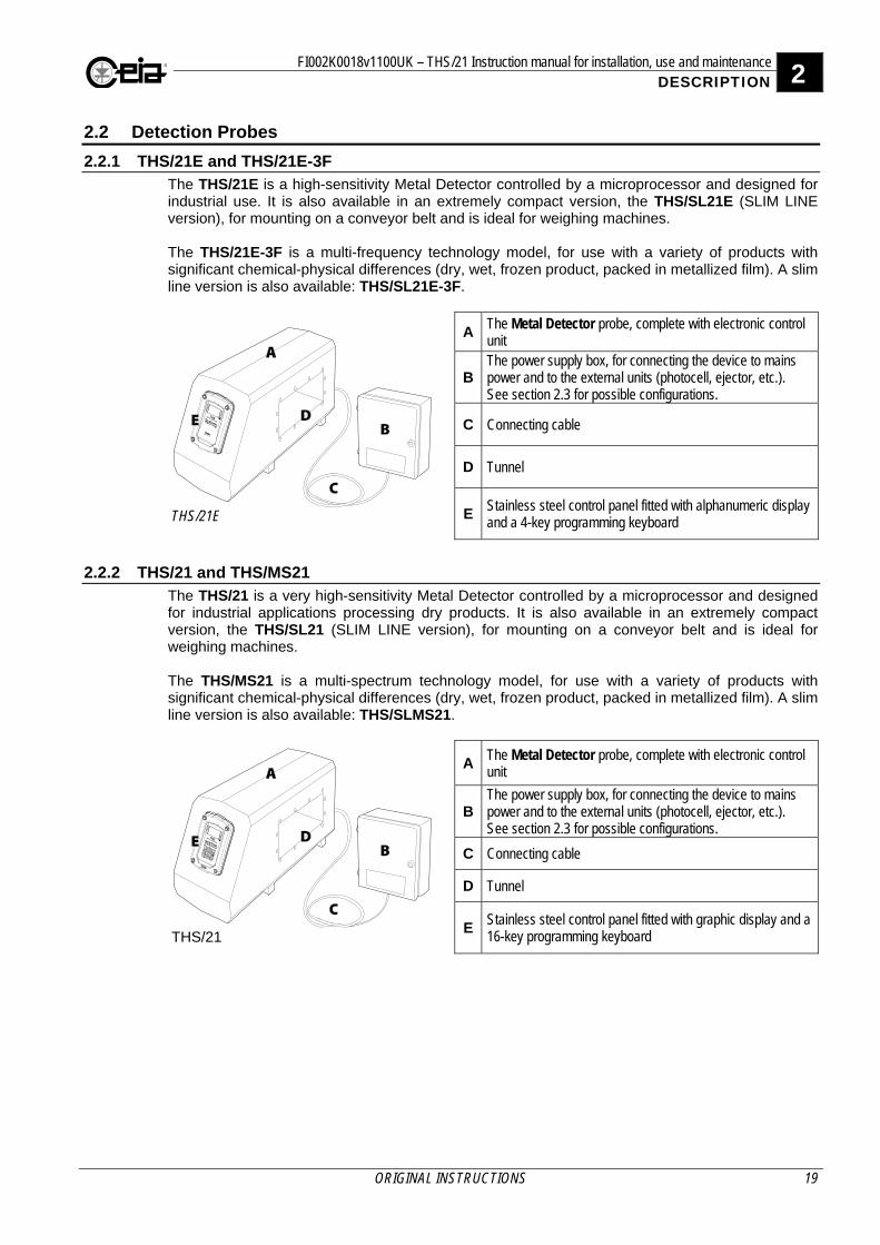
2.2 Detection Probes
2.2.1 THS/21E and THS/21E-3F The THS/21E is a high-sensitivity Metal Detector controlled by a microprocessor and designed for industrial use. It is also available in an extremely compact version, the THS/SL21E (SLIM LINE version), for mounting on a conveyor belt and is ideal for weighing machines. The THS/21E-3F is a multi-frequency technology model, for use with a variety of products with significant chemical-physical differences (dry, wet, frozen product, packed in metallized film). A slim line version is also available: THS/SL21E-3F.
THS/21E
AThe Metal Detector probe, complete with electronic control unit
BThe power supply box, for connecting the device to mains power and to the external units (photocell, ejector, etc.). See section 2.3 for possible configurations.
C Connecting cable
D Tunnel
EStainless steel control panel fitted with alphanumeric display and a 4-key programming keyboard
2.2.2 THS/21 and THS/MS21 The THS/21 is a very high-sensitivity Metal Detector controlled by a microprocessor and designed for industrial applications processing dry products. It is also available in an extremely compact version, the THS/SL21 (SLIM LINE version), for mounting on a conveyor belt and is ideal for weighing machines. The THS/MS21 is a multi-spectrum technology model, for use with a variety of products with significant chemical-physical differences (dry, wet, frozen product, packed in metallized film). A slim line version is also available: THS/SLMS21.
THS/21
AThe Metal Detector probe, complete with electronic control unit
BThe power supply box, for connecting the device to mains power and to the external units (photocell, ejector, etc.). See section 2.3 for possible configurations.
C Connecting cable
D Tunnel
EStainless steel control panel fitted with graphic display and a 16-key programming keyboard
2 FI002K0018v1100UK – THS/21 Instruction manual for installation, use and maintenance DESCRIPTION
20 ORIGINAL INSTRUCTIONS
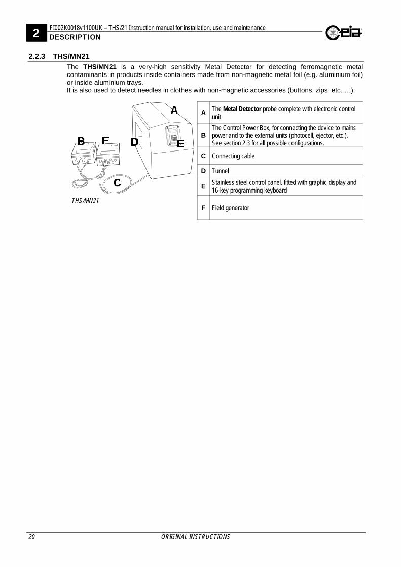
2.2.3 THS/MN21 The THS/MN21 is a very-high sensitivity Metal Detector for detecting ferromagnetic metal contaminants in products inside containers made from non-magnetic metal foil (e.g. aluminium foil) or inside aluminium trays. It is also used to detect needles in clothes with non-magnetic accessories (buttons, zips, etc. …).
THS/MN21
AThe Metal Detector probe complete with electronic control unit
BThe Control Power Box, for connecting the device to mains power and to the external units (photocell, ejector, etc.). See section 2.3 for all possible configurations.
C Connecting cable
D Tunnel
E Stainless steel control panel, fitted with graphic display and 16-key programming keyboard
F Field generator
FI002K0018v1100UK – THS/21 Instruction manual for installation, use and maintenance 2 DESCRIPTION
ORIGINAL INSTRUCTIONS 21
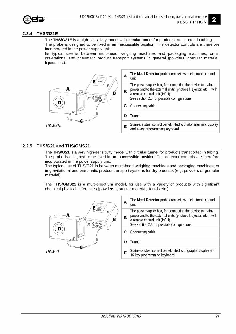
2.2.4 THS/G21E The THS/G21E is a high-sensitivity model with circular tunnel for products transported in tubing. The probe is designed to be fixed in an inaccessible position. The detector controls are therefore incorporated in the power supply unit. Its typical use is between multi-head weighing machines and packaging machines, or in gravitational and pneumatic product transport systems in general (powders, granular material, liquids etc.).
THS/G21E
AThe Metal Detector probe complete with electronic control unit
B
The power supply box, for connecting the device to mains power and to the external units (photocell, ejector, etc.), with a remote control unit (RCU). See section 2.3 for possible configurations.
C Connecting cable
D Tunnel
E Stainless steel control panel, fitted with alphanumeric display and 4-key programming keyboard
2.2.5 THS/G21 and THS/GMS21 The THS/G21 is a very high-sensitivity model with circular tunnel for products transported in tubing. The probe is designed to be fixed in an inaccessible position. The detector controls are therefore incorporated in the power supply unit. The typical use of THS/G21 is between multi-head weighing machines and packaging machines, or in gravitational and pneumatic product transport systems for dry products (e.g. powders or granular material). The THS/GMS21 is a multi-spectrum model, for use with a variety of products with significant chemical-physical differences (powders, granular material, liquids etc.).
THS/G21
AThe Metal Detector probe complete with electronic control unit
B
The power supply box, for connecting the device to mains power and to the external units (photocell, ejector, etc.), with a remote control unit (RCU). See section 2.3 for possible configurations.
C Connecting cable
D Tunnel
E Stainless steel control panel, fitted with graphic display and 16-key programming keyboard
2 FI002K0018v1100UK – THS/21 Instruction manual for installation, use and maintenance DESCRIPTION
22 ORIGINAL INSTRUCTIONS
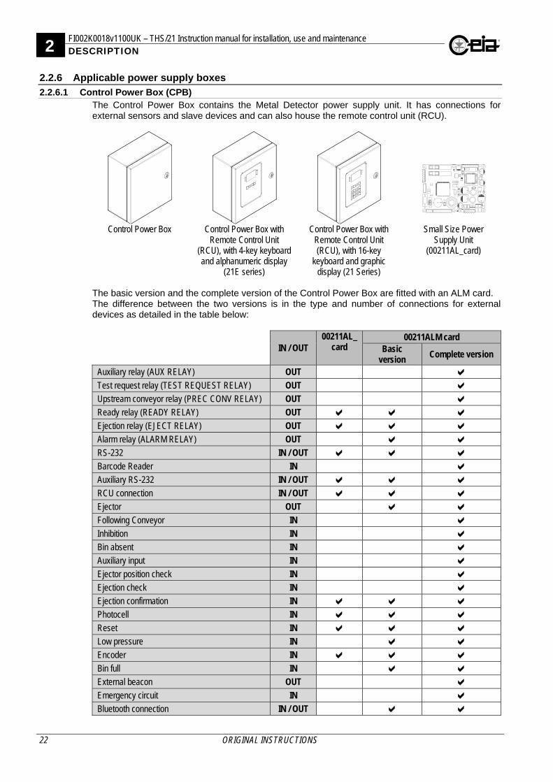
2.2.6 Applicable power supply boxes
2.2.6.1 Control Power Box (CPB) The Control Power Box contains the Metal Detector power supply unit. It has connections for external sensors and slave devices and can also house the remote control unit (RCU).
Control Power Box Control Power Box with
Remote Control Unit (RCU), with 4-key keyboard and alphanumeric display
(21E series)
Control Power Box with Remote Control Unit (RCU), with 16-key
keyboard and graphic display (21 Series)
Small Size Power Supply Unit
(00211AL_card)
The basic version and the complete version of the Control Power Box are fitted with an ALM card. The difference between the two versions is in the type and number of connections for external devices as detailed in the table below:
IN / OUT 00211AL_
card 00211ALM card
Basic version Complete version
Auxiliary relay (AUX RELAY) OUT Test request relay (TEST REQUEST RELAY) OUT Upstream conveyor relay (PREC CONV RELAY) OUT Ready relay (READY RELAY) OUT Ejection relay (EJECT RELAY) OUT Alarm relay (ALARM RELAY) OUT RS-232 IN / OUT Barcode Reader IN Auxiliary RS-232 IN / OUT RCU connection IN / OUT Ejector OUT Following Conveyor IN Inhibition IN Bin absent IN Auxiliary input IN Ejector position check IN Ejection check IN Ejection confirmation IN Photocell IN Reset IN Low pressure IN Encoder IN Bin full IN External beacon OUT Emergency circuit IN Bluetooth connection IN / OUT
FI002K0018v1100UK – THS/21 Instruction manual for installation, use and maintenance 2 DESCRIPTION
ORIGINAL INSTRUCTIONS 23
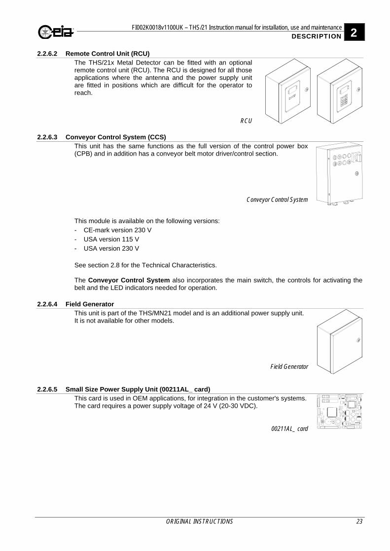
2.2.6.2 Remote Control Unit (RCU) The THS/21x Metal Detector can be fitted with an optional remote control unit (RCU). The RCU is designed for all those applications where the antenna and the power supply unit are fitted in positions which are difficult for the operator to reach.
RCU
2.2.6.3 Conveyor Control System (CCS) This unit has the same functions as the full version of the control power box (CPB) and in addition has a conveyor belt motor driver/control section.
Conveyor Control System
This module is available on the following versions:
- CE-mark version 230 V
- USA version 115 V
- USA version 230 V
See section 2.8 for the Technical Characteristics. The Conveyor Control System also incorporates the main switch, the controls for activating the belt and the LED indicators needed for operation.
2.2.6.4 Field Generator This unit is part of the THS/MN21 model and is an additional power supply unit. It is not available for other models.
Field Generator
2.2.6.5 Small Size Power Supply Unit (00211AL_ card)
This card is used in OEM applications, for integration in the customer's systems. The card requires a power supply voltage of 24 V (20-30 VDC).
00211AL_ card
2 FI002K0018v1100UK – THS/21 Instruction manual for installation, use and maintenance DESCRIPTION
24 ORIGINAL INSTRUCTIONS
2.3 Integrated system with conveyor belt
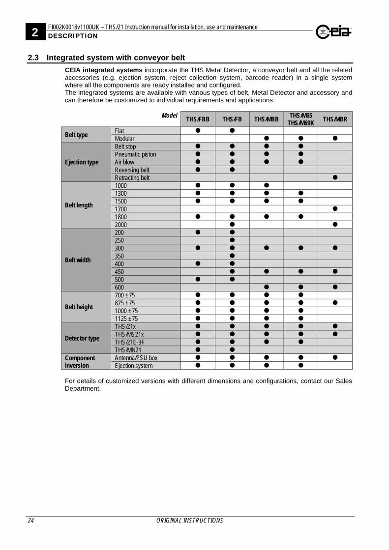
CEIA integrated systems incorporate the THS Metal Detector, a conveyor belt and all the related accessories (e.g. ejection system, reject collection system, barcode reader) in a single system where all the components are ready installed and configured. The integrated systems are available with various types of belt, Metal Detector and accessory and can therefore be customized to individual requirements and applications.
Model THS/FBB THS/FB THS/MBB
THS/M65 THS/M69K THS/MBR
Belt type Flat Modular
Ejection type
Belt stop Pneumatic piston Air blow Reversing belt Retracting belt
Belt length
1000 1300 1500 1700 1800 2000
Belt width
200 250 300 350 400 450 500 600
Belt height
700 ±75 875 ±75 1000 ±75 1125 ±75
Detector type
THS/21x THS/MS21x THS/21E-3F THS/MN21
Component inversion
Antenna/PSU box Ejection system
For details of customized versions with different dimensions and configurations, contact our Sales Department.
FI002K0018v1100UK – THS/21 Instruction manual for installation, use and maintenance 2 DESCRIPTION
ORIGINAL INSTRUCTIONS 25
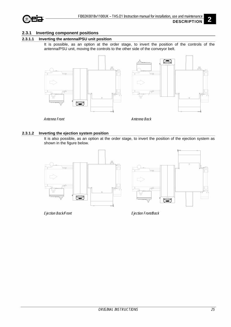
2.3.1 Inverting component positions
2.3.1.1 Inverting the antenna/PSU unit position It is possible, as an option at the order stage, to invert the position of the controls of the antenna/PSU unit, moving the controls to the other side of the conveyor belt.
Antenna Front
Antenna Back
2.3.1.2 Inverting the ejection system position It is also possible, as an option at the order stage, to invert the position of the ejection system as shown in the figure below.
Ejection Back/Front
Ejection Front/Back
2 FI002K0018v1100UK – THS/21 Instruction manual for installation, use and maintenance DESCRIPTION
26 ORIGINAL INSTRUCTIONS
2.3.2 Models
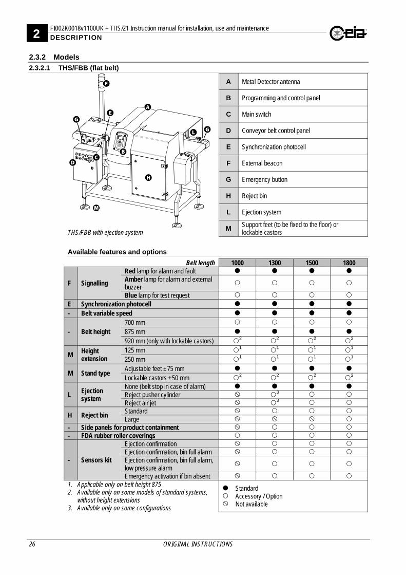
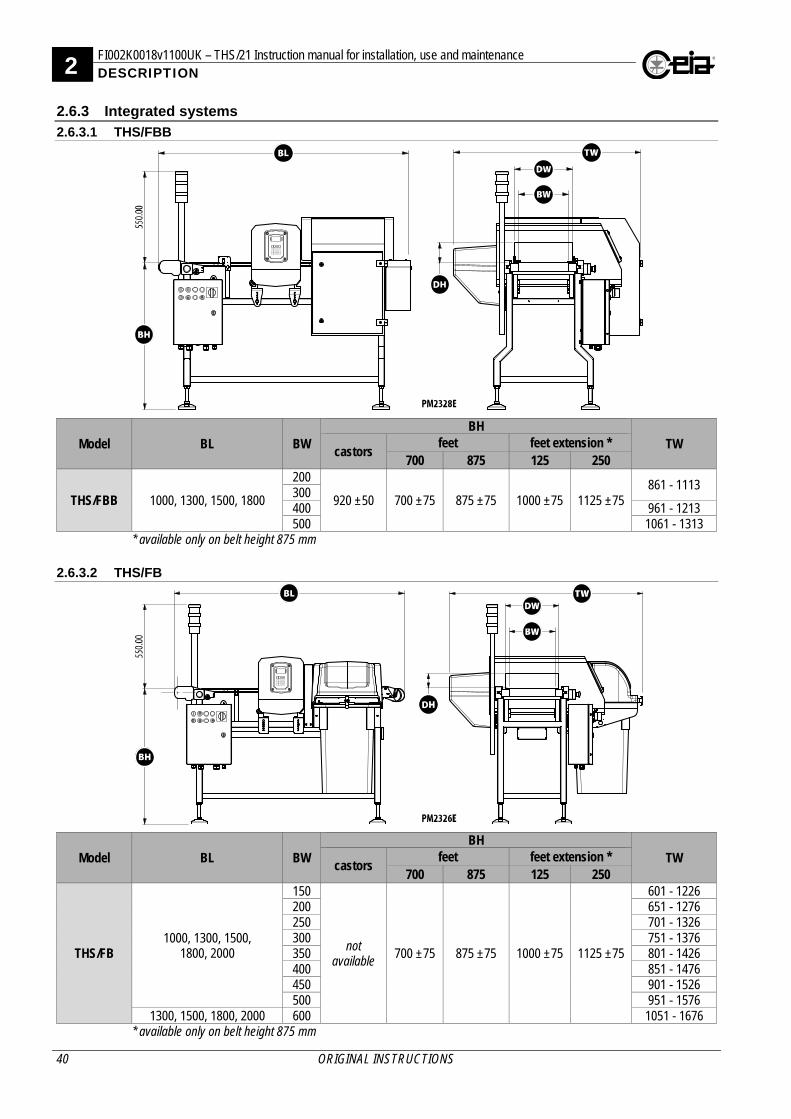
2.3.2.1 THS/FBB (flat belt)
THS/FBB with ejection system
A Metal Detector antenna
B Programming and control panel
C Main switch
D Conveyor belt control panel
E Synchronization photocell
F External beacon
G Emergency button
H Reject bin
L Ejection system
M Support feet (to be fixed to the floor) or lockable castors
Available features and options
Belt length 1000 1300 1500 1800
F Signalling
Red lamp for alarm and fault Amber lamp for alarm and external buzzer
Blue lamp for test request
E Synchronization photocell
- Belt variable speed
- Belt height 700 mm
875 mm
920 mm (only with lockable castors) 2 2 2 2
M Height extension
125 mm 1 1 1 1 250 mm 1 1 1 1
M Stand type Adjustable feet ±75 mm
Lockable castors ±50 mm 2 2 2 2
L Ejection system
None (belt stop in case of alarm) Reject pusher cylinder 3 Reject air jet 3
H Reject bin Standard Large
- Side panels for product containment - FDA rubber roller coverings
- Sensors kit
Ejection confirmation Ejection confirmation, bin full alarm Ejection confirmation, bin full alarm, low pressure alarm
Emergency activation if bin absent 1. Applicable only on belt height 875 2. Available only on some models of standard systems,
without height extensions 3. Available only on some configurations
Standard Accessory / Option Not available
FI002K0018v1100UK – THS/21 Instruction manual for installation, use and maintenance 2 DESCRIPTION
ORIGINAL INSTRUCTIONS 27
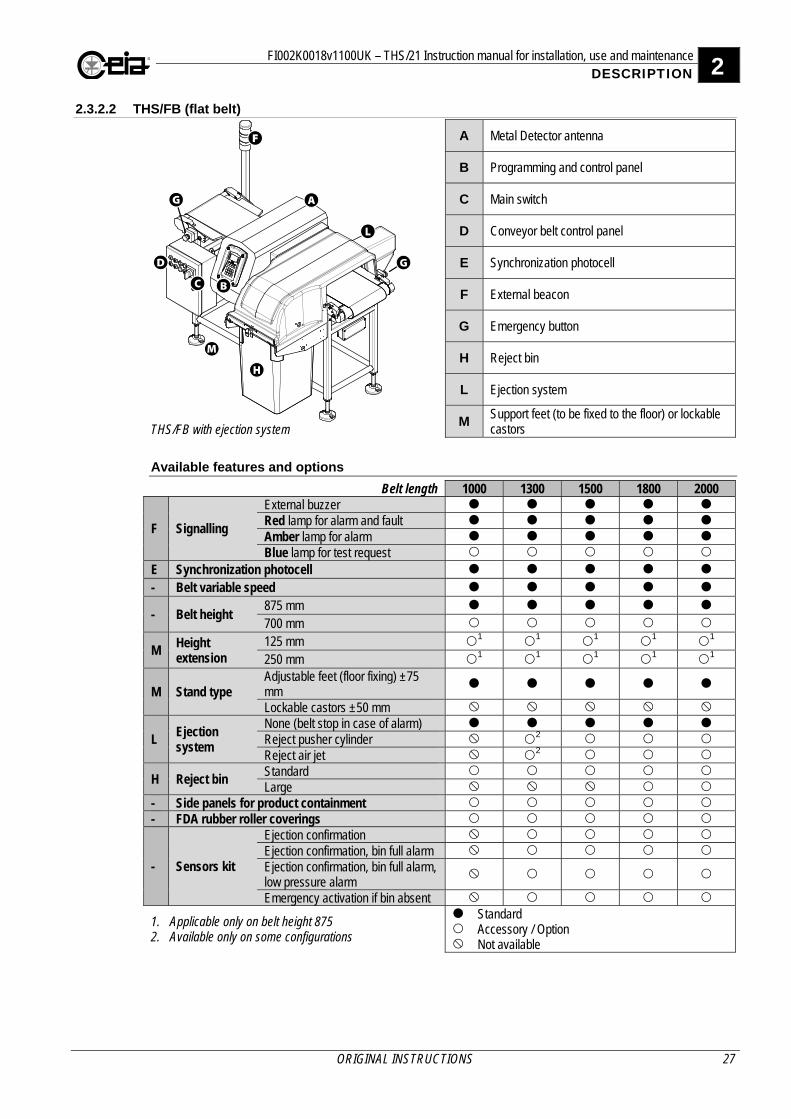
2.3.2.2 THS/FB (flat belt)
THS/FB with ejection system
A Metal Detector antenna
B Programming and control panel
C Main switch
D Conveyor belt control panel
E Synchronization photocell
F External beacon
G Emergency button
H Reject bin
L Ejection system
M Support feet (to be fixed to the floor) or lockable castors
Available features and options
Belt length 1000 1300 1500 1800 2000
F Signalling
External buzzer Red lamp for alarm and fault Amber lamp for alarm Blue lamp for test request
E Synchronization photocell
- Belt variable speed
- Belt height 875 mm
700 mm
M Height extension
125 mm 1 1 1 1 1 250 mm 1 1 1 1 1
M Stand type Adjustable feet (floor fixing) ±75 mm
Lockable castors ±50 mm
L Ejection system
None (belt stop in case of alarm) Reject pusher cylinder 2 Reject air jet 2
H Reject bin Standard Large
- Side panels for product containment - FDA rubber roller coverings
- Sensors kit
Ejection confirmation Ejection confirmation, bin full alarm Ejection confirmation, bin full alarm, low pressure alarm
Emergency activation if bin absent
1. Applicable only on belt height 875 2. Available only on some configurations
Standard Accessory / Option Not available
2 FI002K0018v1100UK – THS/21 Instruction manual for installation, use and maintenance DESCRIPTION
28 ORIGINAL INSTRUCTIONS
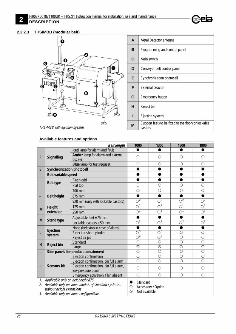
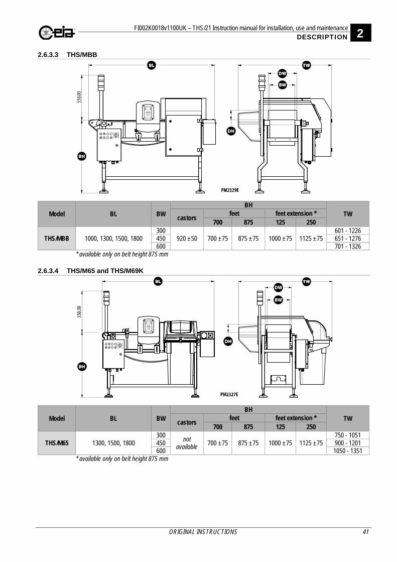
2.3.2.3 THS/MBB (modular belt)
THS/MBB with ejection system
A Metal Detector antenna
B Programming and control panel
C Main switch
D Conveyor belt control panel
E Synchronization photocell
F External beacon
G Emergency button
H Reject bin
L Ejection system
M Support feet (to be fixed to the floor) or lockable castors
Available features and options
Belt length 1000 1300 1500 1800
F Signalling
Red lamp for alarm and fault Amber lamp for alarm and external buzzer
Blue lamp for test request
E Synchronization photocell
- Belt variable speed
- Belt type Flush grid
Flat top
- Belt height 700 mm
875 mm
920 mm (only with lockable castors) 2 2 2 2
M Height extension
125 mm 1 1 1 1 250 mm 1 1 1 1
M Stand type Adjustable feet ±75 mm
Lockable castors ±50 mm 2 2 2 2
L Ejection system
None (belt stop in case of alarm) Reject pusher cylinder 3 3 Reject air jet 3 3
H Reject bin Standard Large
- Side panels for product containment
- Sensors kit
Ejection confirmation Ejection confirmation, bin full alarm Ejection confirmation, bin full alarm, low pressure alarm
Emergency activation if bin absent 1. Applicable only on belt height 875 2. Available only on some models of standard systems,
without height extensions 3. Available only on some configurations
Standard Accessory / Option Not available
FI002K0018v1100UK – THS/21 Instruction manual for installation, use and maintenance 2 DESCRIPTION
ORIGINAL INSTRUCTIONS 29
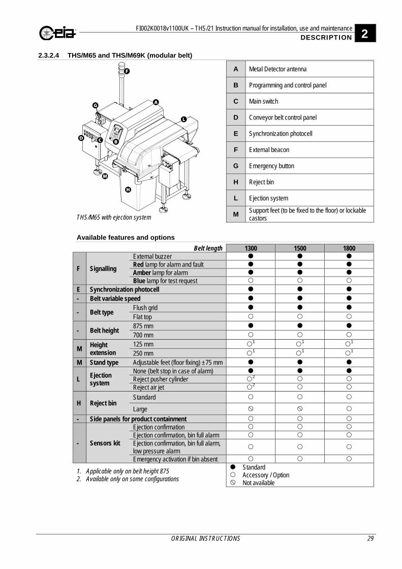
2.3.2.4 THS/M65 and THS/M69K (modular belt)
THS/M65 with ejection system
A Metal Detector antenna
B Programming and control panel
C Main switch
D Conveyor belt control panel
E Synchronization photocell
F External beacon
G Emergency button
H Reject bin
L Ejection system
M Support feet (to be fixed to the floor) or lockable castors
Available features and options
Belt length 1300 1500 1800
F Signalling
External buzzer Red lamp for alarm and fault Amber lamp for alarm Blue lamp for test request
E Synchronization photocell
- Belt variable speed
- Belt type Flush grid
Flat top
- Belt height 875 mm
700 mm
M Height extension
125 mm 1 1 1 250 mm 1 1 1
M Stand type Adjustable feet (floor fixing) ±75 mm
L Ejection system
None (belt stop in case of alarm) Reject pusher cylinder 2 Reject air jet 2
H Reject bin Standard
Large
- Side panels for product containment
- Sensors kit
Ejection confirmation Ejection confirmation, bin full alarm Ejection confirmation, bin full alarm, low pressure alarm
Emergency activation if bin absent
1. Applicable only on belt height 875 2. Available only on some configurations
Standard Accessory / Option Not available
2 FI002K0018v1100UK – THS/21 Instruction manual for installation, use and maintenance DESCRIPTION
30 ORIGINAL INSTRUCTIONS
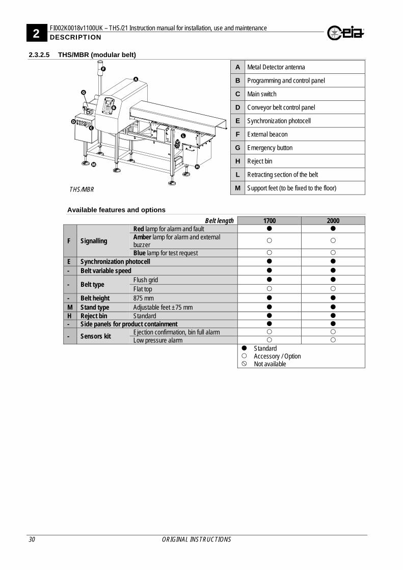
2.3.2.5 THS/MBR (modular belt)
THS/MBR
A Metal Detector antenna
B Programming and control panel
C Main switch
D Conveyor belt control panel
E Synchronization photocell
F External beacon
G Emergency button
H Reject bin
L Retracting section of the belt
M Support feet (to be fixed to the floor)
Available features and options
Belt length 1700 2000
F Signalling
Red lamp for alarm and fault Amber lamp for alarm and external buzzer
Blue lamp for test request
E Synchronization photocell
- Belt variable speed
- Belt type Flush grid
Flat top
- Belt height 875 mm
M Stand type Adjustable feet ±75 mm H Reject bin Standard - Side panels for product containment
- Sensors kit Ejection confirmation, bin full alarm Low pressure alarm
Standard Accessory / Option Not available
FI002K0018v1100UK – THS/21 Instruction manual for installation, use and maintenance 2 DESCRIPTION
ORIGINAL INSTRUCTIONS 31
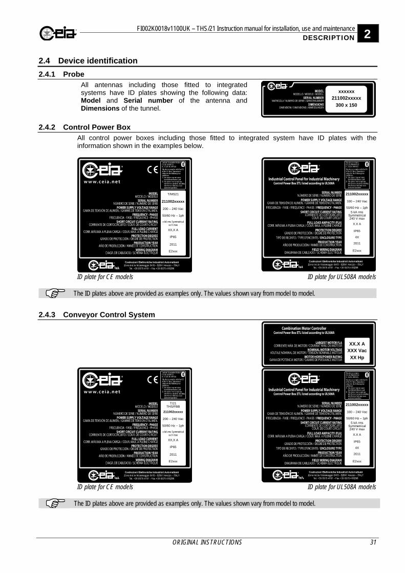
2.4 Device identification
2.4.1 Probe All antennas including those fitted to integrated systems have ID plates showing the following data: Model and Serial number of the antenna and Dimensions of the tunnel.
xxxxxx211002xxxxx
300 x 150
2.4.2 Control Power Box All control power boxes including those fitted to integrated system have ID plates with the information shown in the examples below.
211002xxxxx
200 – 240 Vac
50/60 Hz – 1ph
x kA rms Symmetrical xx V max
XX,X A
IP65
2011
E2xxx
T/MS21 211002xxxxx
100 – 240 Vac
50/60 Hz – 1ph
5 kA rms Symmetrical 240 V max
X.X A
IP65
4X
2011
E2xxx
ID plate for CE models ID plate for UL508A models
The ID plates above are provided as examples only. The values shown vary from model to model.
2.4.3 Conveyor Control System
211002xxxxx
200 – 240 Vac
50/60 Hz – 1ph
x kA rms Symmetrical xx V max
XX,X A
IP65
2011
E2xxx
T/21THS/FBB
XX.X AXXX Vac
XX Hp
211002xxxxx
100 – 240 Vac
50/60 Hz – 1ph
5 kA rms Symmetrical 240 V max
X.X A
IP65
4X
2011
E2xxx
ID plate for CE models ID plate for UL508A models
The ID plates above are provided as examples only. The values shown vary from model to model.

2 FI002K0018v1100UK – THS/21 Instruction manual for installation, use and maintenance DESCRIPTION
32 ORIGINAL INSTRUCTIONS
2.4.4 CEIA conveyor structure CEIA integrated systems have an additional ID plate for the conveyor belt as shown in the example here. THS/FB
211002xxxxx
1500 x 300
FI002K0018v1100UK – THS/21 Instruction manual for installation, use and maintenance 2 DESCRIPTION
ORIGINAL INSTRUCTIONS 33
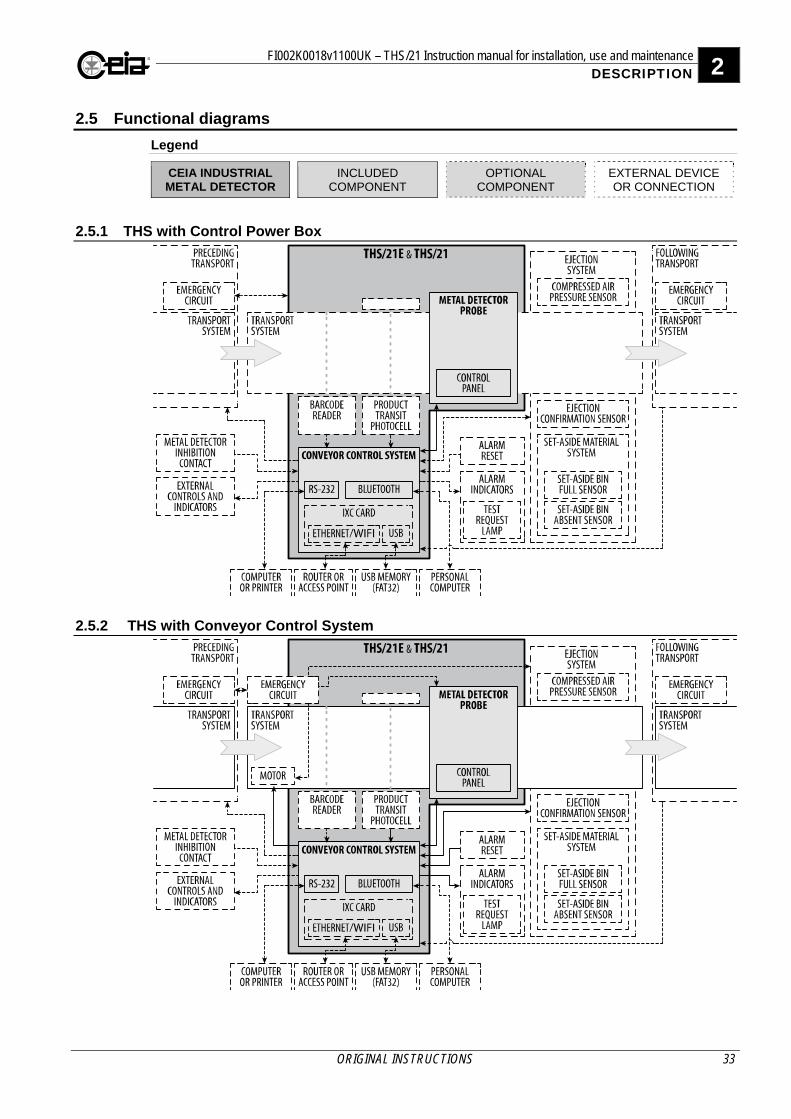
2.5 Functional diagrams
Legend
CEIA INDUSTRIAL METAL DETECTOR
INCLUDED COMPONENT
OPTIONAL COMPONENT
EXTERNAL DEVICE OR CONNECTION
2.5.1 THS with Control Power Box
2.5.2 THS with Conveyor Control System
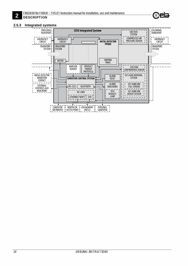
2 FI002K0018v1100UK – THS/21 Instruction manual for installation, use and maintenance DESCRIPTION
34 ORIGINAL INSTRUCTIONS
2.5.3 Integrated systems
FI002K0018v1100UK – THS/21 Instruction manual for installation, use and maintenance 2 DESCRIPTION
ORIGINAL INSTRUCTIONS 35
2.6 Dimensions
2.6.1 Probes
2.6.1.1 THS/21, THS/MS21, THS/21E, THS/21E-3F
Series DW DH TH DL FHL TP FHP FHD DC TW
A 200, 250, ..., 1000 100, 125, 150,175 395 290 190 105
TP-30 DW+60
205 DW+420
B 350, 400, ..., 900 200, 225, 250, 275 550 390 290 160 280 DW+520
C 450, 500, ..., 1000 300, 325, 350 635 490 390 210 320 DW+620
Series DW DH TH DL FHL TP FHP FHD DC TW
D 500, 550, 600, 700,
800, 900, 1000, 1100, 1200, 1300
400, 450, 500 905 490 390 260 TP-30 DW+60 455 DW+720
2 FI002K0018v1100UK – THS/21 Instruction manual for installation, use and maintenance DESCRIPTION
36 ORIGINAL INSTRUCTIONS
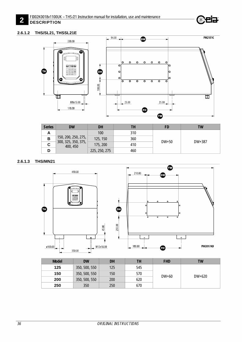
2.6.1.2 THS/SL21, THSSL21E
Series DW DH TH FD TW
A 150, 200, 250, 275, 300, 325, 350, 375,
400, 450
100 310
DW+50 DW+387 B 125, 150 360
C 175, 200 410
D 225, 250, 275 460
2.6.1.3 THS/MN21
Model DW DH TH FHD TW
125 350, 500, 550 125 545
DW+60 DW+620 150 350, 500, 550 150 570
200 350, 500, 550 200 620
250 350 250 670
FI002K0018v1100UK – THS/21 Instruction manual for installation, use and maintenance 2 DESCRIPTION
ORIGINAL INSTRUCTIONS 37
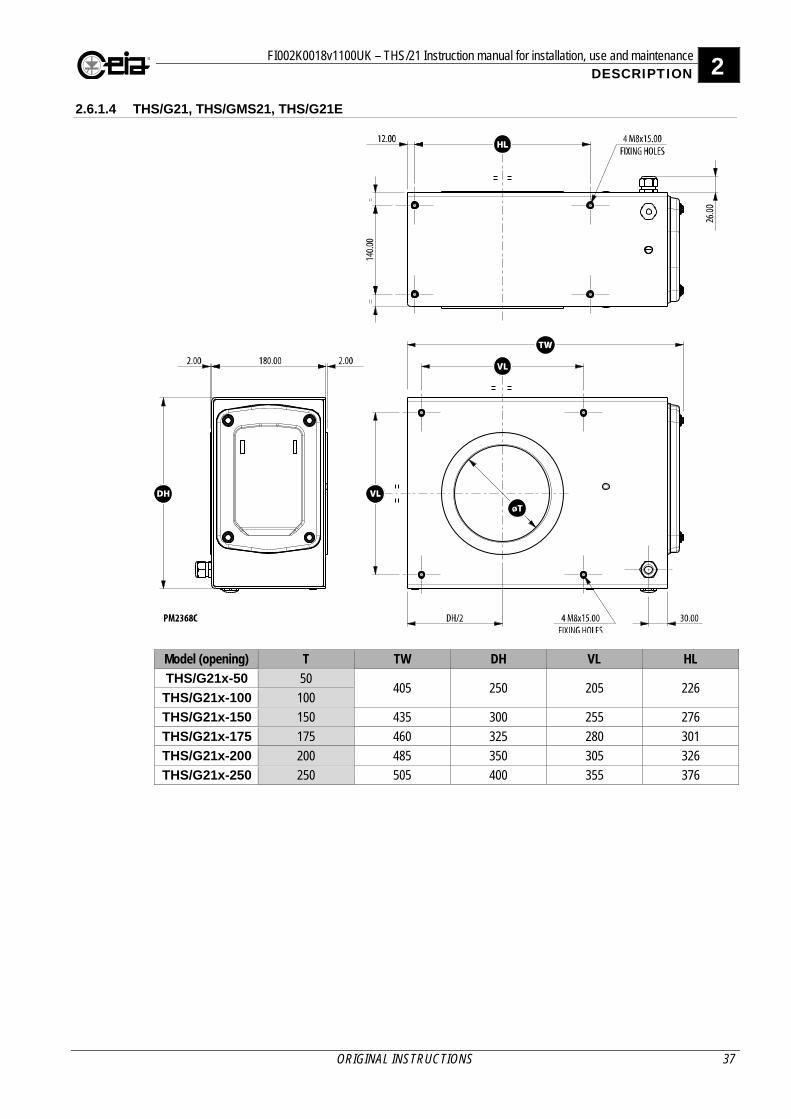
2.6.1.4 THS/G21, THS/GMS21, THS/G21E
Model (opening) T TW DH VL HL
THS/G21x-50 50 405 250 205 226
THS/G21x-100 100
THS/G21x-150 150 435 300 255 276
THS/G21x-175 175 460 325 280 301
THS/G21x-200 200 485 350 305 326
THS/G21x-250 250 505 400 355 376
2 FI002K0018v1100UK – THS/21 Instruction manual for installation, use and maintenance DESCRIPTION
38 ORIGINAL INSTRUCTIONS
2.6.2 Power supply units
2.6.2.1 Control Power Box (CPB) and Field Generator (MAG)
2.6.2.2 Control Power Box with Remote Control Unit (THS/21E)
FI002K0018v1100UK – THS/21 Instruction manual for installation, use and maintenance 2 DESCRIPTION
ORIGINAL INSTRUCTIONS 39
2.6.2.3 Control Power Box with Remote Control Unit (THS/21)
2.6.2.4 Conveyor Control System
2.6.2.5 Small size power supply unit (00211AL_ card)
2 FI002K0018v1100UK – THS/21 Instruction manual for installation, use and maintenance DESCRIPTION
40 ORIGINAL INSTRUCTIONS
2.6.3 Integrated systems
2.6.3.1 THS/FBB
Model BL BW BH
TW castors
feet feet extension * 700 875 125 250
THS/FBB 1000, 1300, 1500, 1800
200
920 ±50 700 ±75 875 ±75 1000 ±75 1125 ±75 861 - 1113
300 400 961 - 1213 500 1061 - 1313
* available only on belt height 875 mm
2.6.3.2 THS/FB
Model BL BW BH
TW castors
feet feet extension * 700 875 125 250
THS/FB 1000, 1300, 1500,
1800, 2000
150
not available
700 ±75 875 ±75 1000 ±75 1125 ±75
601 - 1226 200 651 - 1276 250 701 - 1326 300 751 - 1376 350 801 - 1426 400 851 - 1476 450 901 - 1526 500 951 - 1576
1300, 1500, 1800, 2000 600 1051 - 1676 * available only on belt height 875 mm
FI002K0018v1100UK – THS/21 Instruction manual for installation, use and maintenance 2 DESCRIPTION
ORIGINAL INSTRUCTIONS 41
2.6.3.3 THS/MBB
Model BL BW BH
TW castors
feet feet extension * 700 875 125 250
THS/MBB 1000, 1300, 1500, 1800 300
920 ±50 700 ±75 875 ±75 1000 ±75 1125 ±75 601 - 1226
450 651 - 1276 600 701 - 1326
* available only on belt height 875 mm
2.6.3.4 THS/M65 and THS/M69K
Model BL BW BH
TW castors
feet feet extension * 700 875 125 250
THS/M65 1300, 1500, 1800 300
not available 700 ±75 875 ±75 1000 ±75 1125 ±75
750 - 1051 450 900 - 1201 600 1050 - 1351
* available only on belt height 875 mm
2 FI002K0018v1100UK – THS/21 Instruction manual for installation, use and maintenance DESCRIPTION
42 ORIGINAL INSTRUCTIONS
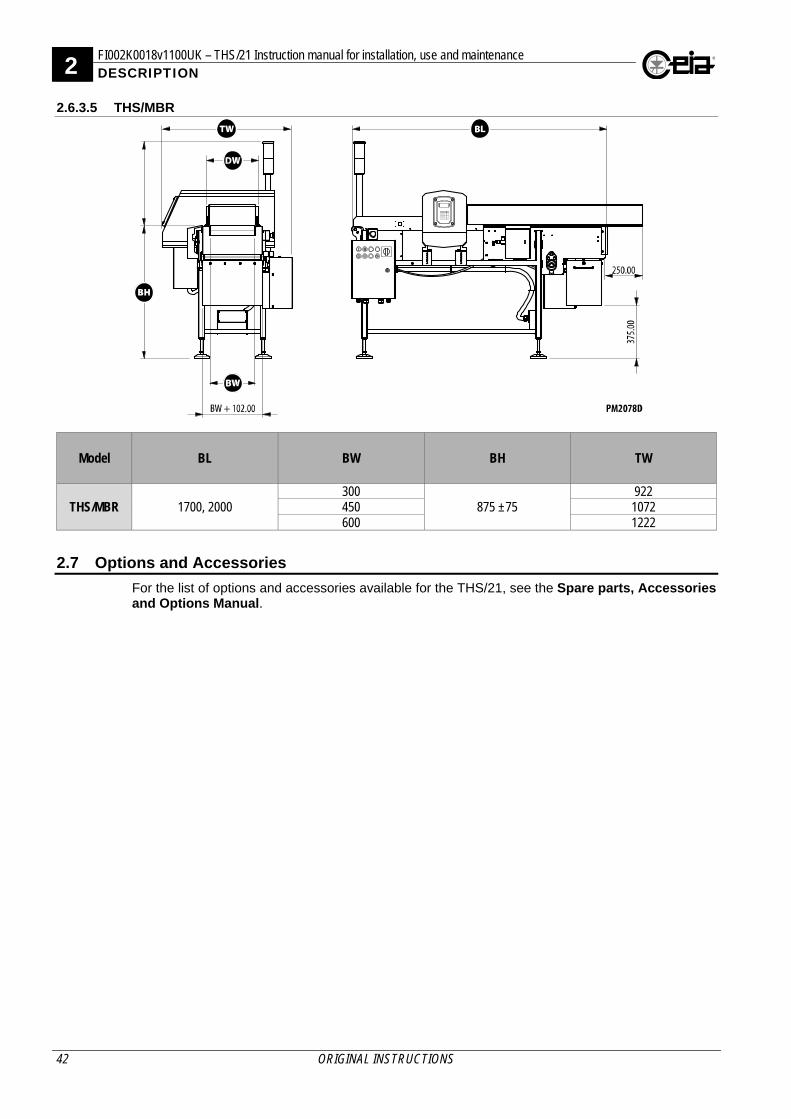
2.6.3.5 THS/MBR
Model BL BW BH TW
THS/MBR 1700, 2000 300
875 ±75 922
450 1072 600 1222
2.7 Options and Accessories
For the list of options and accessories available for the THS/21, see the Spare parts, Accessories and Options Manual.
FI002K0018v1100UK – THS/21 Instruction manual for installation, use and maintenance 2 DESCRIPTION
ORIGINAL INSTRUCTIONS 43
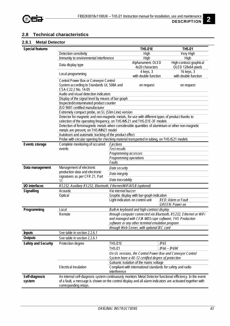
2.8 Technical characteristics
2.8.1 Metal Detector
Special features THS/21E THS/21 Detection sensitivity High Very High Immunity to environmental interference High High
Data display type Alphanumeric OLED
4x20 characters High-contrast graphical
OLED 128x64 pixels
Local programming 4 keys, 3
with double function 16 keys, 3
with double function Control Power Box or Conveyor Control System according to Standards UL 508A and CSA-C22.2 No. 14-05
on request on request
Audio and visual detection indicators Display of the signal level by means of bar graph Inspected/contaminated product counter ISO 9001 certified manufacturer Extremely compact probe, on SL (Slim Line) version Detector for magnetic and non-magnetic metals, for use with different types of product thanks to selection of the operating frequency, on THS/MS21 and THS/21E-3F models Detection of ferromagnetic metals when considerable quantities of aluminium or other non-magnetic metals are present, on THS/MN21 model Autolearn and automatic tracking of the product effect Probe with circular opening for checking material transported in tubing, on THS/G21 models
Events storage Complete monitoring of occurred events
Ejections Test results Programming accesses Programming operations Faults
Data management Management of electronic production data and electronic signatures as per CFR 21, Part 11
Data security
Data integrity
Data traceability
I/O interfaces RS232, Auxiliary RS232, Bluetooth, Ethernet/WiFi/USB (optional) Signalling Acoustic Via internal buzzer
Optical Graphic display with bar-graph indication Light indicators on control unit RED: Alarm or Fault
GREEN: Power on Programming Local Built-in keyboard and high-contrast display
Remote through computer connected via Bluetooth, RS232, Ethernet or WiFi and managed with CEIA MDScope software, THS Production software or any other terminal emulation program through Web Server, with optional IXC card
Inputs See table in section 2.2.6.1 Outputs See table in section 2.2.6.1 Safety and Security Protection degree THS/21E IP65
THS/21 IP66 – IP69K On UL versions, the Control Power Box and Conveyor Control System have a 4X-12 certified degree of protection
Electrical insulation Galvanic isolation of the mains voltage Compliant with international standards for safety and radio interference
Self-diagnosis system
An internal self-diagnosis system continuously monitors Metal Detector functional efficiency. In the event of a fault, a message is shown on the control display and all alarm indicators are activated together with corresponding relays.
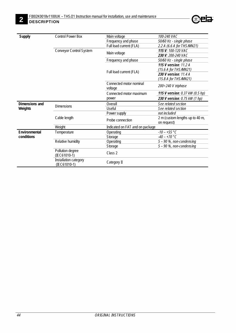
2 FI002K0018v1100UK – THS/21 Instruction manual for installation, use and maintenance DESCRIPTION
44 ORIGINAL INSTRUCTIONS
Supply Control Power Box Main voltage 100-240 VAC
Frequency and phase 50/60 Hz - single phase Full load current (FLA) 2.2 A (6.6 A for THS/MN21)
Conveyor Control System Main voltage
115 V: 100-120 VAC 230 V: 200-240 VAC
Frequency and phase 50/60 Hz - single phase
Full load current (FLA)
115 V version: 11.2 A (15.6 A for THS/MN21) 230 V version: 11.4 A (15.8 A for THS/MN21)
Connected motor nominal voltage
200÷240 V triphase
Connected motor maximum power
115 V version: 0.37 kW (0.5 hp) 230 V version: 0.75 kW (1 hp)
Dimensions and Weights
Dimensions Overall See related section Useful See related section
Cable length Power supply not included
Probe connection 2 m (custom lengths up to 40 m, on request)
Weight Indicated on FAT and on package Environmental conditions
Temperature Operating -10 – +55 °C Storage -40 – +70 °C
Relative humidity Operating 5 – 90 %, non-condensing Storage 5 – 90 %, non-condensing
Pollution degree (IEC61010-1) Class 2
Installation category (IEC61010-1)
Category II
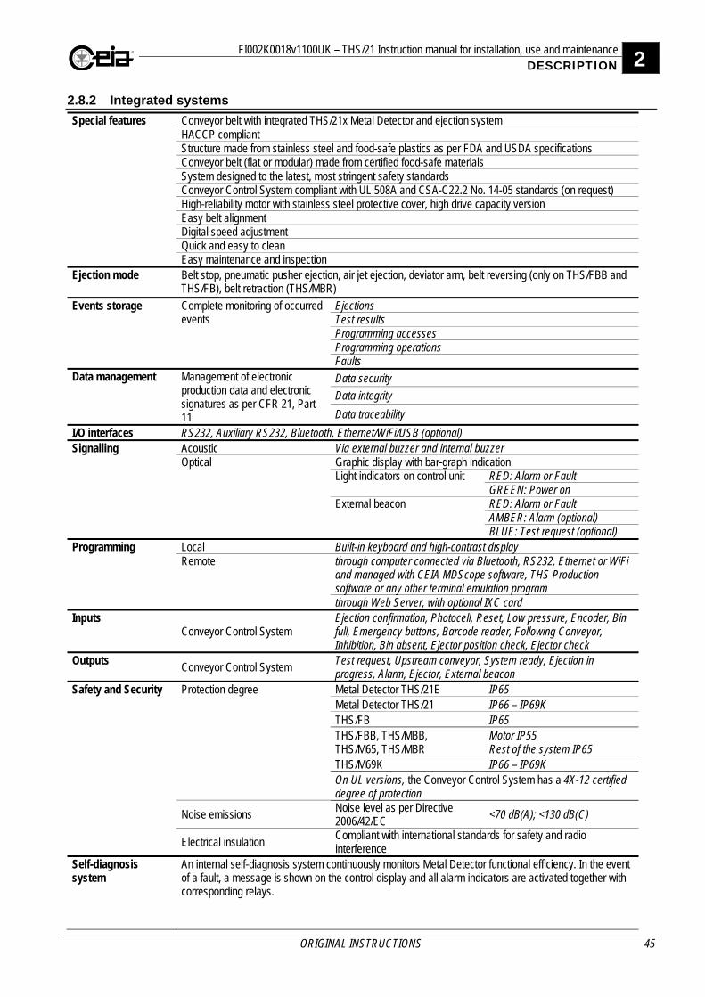
FI002K0018v1100UK – THS/21 Instruction manual for installation, use and maintenance 2 DESCRIPTION
ORIGINAL INSTRUCTIONS 45
2.8.2 Integrated systems
Special features Conveyor belt with integrated THS/21x Metal Detector and ejection system HACCP compliant Structure made from stainless steel and food-safe plastics as per FDA and USDA specifications Conveyor belt (flat or modular) made from certified food-safe materials System designed to the latest, most stringent safety standards Conveyor Control System compliant with UL 508A and CSA-C22.2 No. 14-05 standards (on request) High-reliability motor with stainless steel protective cover, high drive capacity version Easy belt alignment Digital speed adjustment Quick and easy to clean Easy maintenance and inspection
Ejection mode Belt stop, pneumatic pusher ejection, air jet ejection, deviator arm, belt reversing (only on THS/FBB and THS/FB), belt retraction (THS/MBR)
Events storage Complete monitoring of occurred events
Ejections Test results Programming accesses Programming operations Faults
Data management Management of electronic production data and electronic signatures as per CFR 21, Part 11
Data security
Data integrity
Data traceability
I/O interfaces RS232, Auxiliary RS232, Bluetooth, Ethernet/WiFi/USB (optional) Signalling Acoustic Via external buzzer and internal buzzer
Optical Graphic display with bar-graph indication Light indicators on control unit RED: Alarm or Fault
GREEN: Power on External beacon RED: Alarm or Fault
AMBER: Alarm (optional) BLUE: Test request (optional)
Programming
Local Built-in keyboard and high-contrast display Remote through computer connected via Bluetooth, RS232, Ethernet or WiFi
and managed with CEIA MDScope software, THS Production software or any other terminal emulation program through Web Server, with optional IXC card
Inputs Conveyor Control System
Ejection confirmation, Photocell, Reset, Low pressure, Encoder, Bin full, Emergency buttons, Barcode reader, Following Conveyor, Inhibition, Bin absent, Ejector position check, Ejector check
Outputs Conveyor Control System
Test request, Upstream conveyor, System ready, Ejection in progress, Alarm, Ejector, External beacon
Safety and Security Protection degree Metal Detector THS/21E IP65 Metal Detector THS/21 IP66 – IP69K THS/FB IP65 THS/FBB, THS/MBB, THS/M65, THS/MBR
Motor IP55 Rest of the system IP65
THS/M69K IP66 – IP69K On UL versions, the Conveyor Control System has a 4X-12 certified degree of protection
Noise emissions Noise level as per Directive 2006/42/EC
<70 dB(A); <130 dB(C)
Electrical insulation Compliant with international standards for safety and radio interference
Self-diagnosis system
An internal self-diagnosis system continuously monitors Metal Detector functional efficiency. In the event of a fault, a message is shown on the control display and all alarm indicators are activated together with corresponding relays.
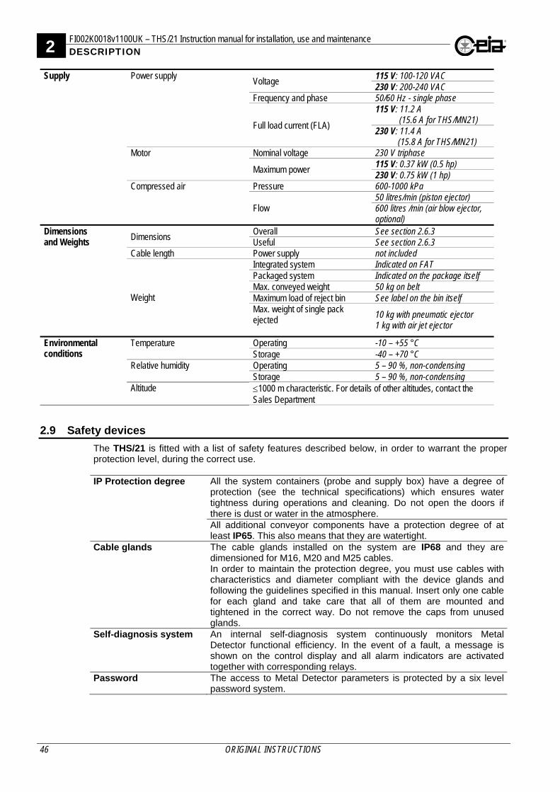
2 FI002K0018v1100UK – THS/21 Instruction manual for installation, use and maintenance DESCRIPTION
46 ORIGINAL INSTRUCTIONS
Supply
Power supply Voltage
115 V: 100-120 VAC 230 V: 200-240 VAC
Frequency and phase 50/60 Hz - single phase
Full load current (FLA)
115 V: 11.2 A (15.6 A for THS/MN21)
230 V: 11.4 A (15.8 A for THS/MN21)
Motor Nominal voltage 230 V triphase
Maximum power 115 V: 0.37 kW (0.5 hp) 230 V: 0.75 kW (1 hp)
Compressed air Pressure 600-1000 kPa
Flow 50 litres/min (piston ejector) 600 litres /min (air blow ejector, optional)
Dimensions and Weights
Dimensions Overall See section 2.6.3 Useful See section 2.6.3
Cable length Power supply not included
Weight
Integrated system Indicated on FAT Packaged system Indicated on the package itself Max. conveyed weight 50 kg on belt Maximum load of reject bin See label on the bin itself Max. weight of single pack ejected
10 kg with pneumatic ejector 1 kg with air jet ejector
Environmental conditions
Temperature Operating -10 – +55 °C Storage -40 – +70 °C
Relative humidity Operating 5 – 90 %, non-condensing Storage 5 – 90 %, non-condensing
Altitude 1000 m characteristic. For details of other altitudes, contact the Sales Department
2.9 Safety devices
The THS/21 is fitted with a list of safety features described below, in order to warrant the proper protection level, during the correct use. IP Protection degree All the system containers (probe and supply box) have a degree of
protection (see the technical specifications) which ensures water tightness during operations and cleaning. Do not open the doors if there is dust or water in the atmosphere. All additional conveyor components have a protection degree of at least IP65. This also means that they are watertight.
Cable glands The cable glands installed on the system are IP68 and they are dimensioned for M16, M20 and M25 cables. In order to maintain the protection degree, you must use cables with characteristics and diameter compliant with the device glands and following the guidelines specified in this manual. Insert only one cable for each gland and take care that all of them are mounted and tightened in the correct way. Do not remove the caps from unused glands.
Self-diagnosis system An internal self-diagnosis system continuously monitors Metal Detector functional efficiency. In the event of a fault, a message is shown on the control display and all alarm indicators are activated together with corresponding relays.
Password The access to Metal Detector parameters is protected by a six level password system.
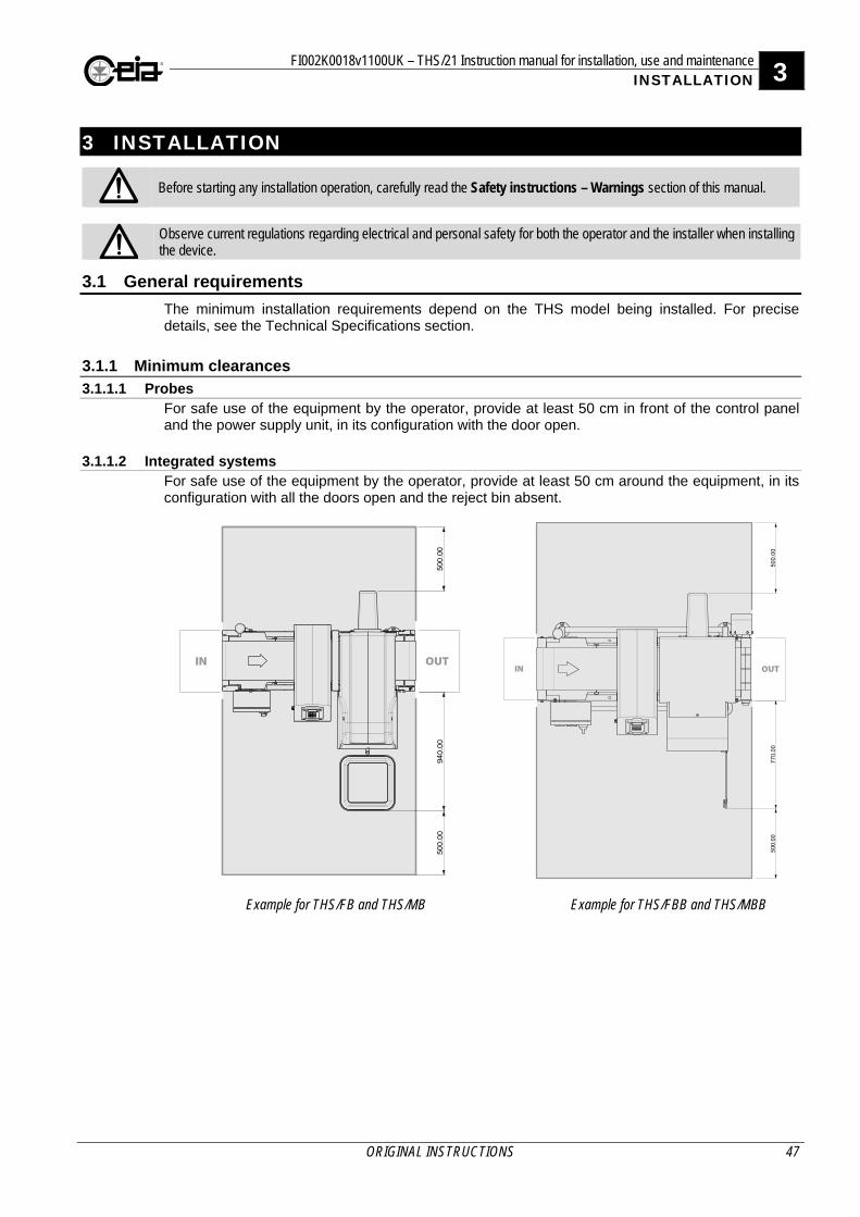
FI002K0018v1100UK – THS/21 Instruction manual for installation, use and maintenance 3 INSTALLATION
ORIGINAL INSTRUCTIONS 47
3 INSTALLATION
Before starting any installation operation, carefully read the Safety instructions – Warnings section of this manual.
Observe current regulations regarding electrical and personal safety for both the operator and the installer when installing the device.
3.1 General requirements
The minimum installation requirements depend on the THS model being installed. For precise details, see the Technical Specifications section.
3.1.1 Minimum clearances
3.1.1.1 Probes For safe use of the equipment by the operator, provide at least 50 cm in front of the control panel and the power supply unit, in its configuration with the door open.
3.1.1.2 Integrated systems For safe use of the equipment by the operator, provide at least 50 cm around the equipment, in its configuration with all the doors open and the reject bin absent.
Example for THS/FB and THS/MB Example for THS/FBB and THS/MBB
3 FI002K0018v1100UK – THS/21 Instruction manual for installation, use and maintenance INSTALLATION
48 ORIGINAL INSTRUCTIONS
3.1.2 General installation guidelines for non-integrated models Some THS models are designed for installation on conveyor belts or production lines provided and set up by the customer. When designing these systems customers are advised to follow the guidelines given in this manual to ensure that they get top performance from their CEIA Metal Detectors.
The following notes provide additional instructions necessary for installing the detector on a conveyor belt or other transport system set up by the customer. For the installation checks you need to be able to switch on the system, understand the signals given during use and set the applicable operating parameters. These operations are described in the first part of section 4 – Use of the device.
3.1.2.1 Controls and Power Supply box Standard EN 60204-1 specifies that the main switch and the other controls to be used by the operator must be at a height of between 60 and 180 cm from the floor. In cases where it is not possible to comply with this specification, you must install an additional remote control unit (RCU) at the height specified.
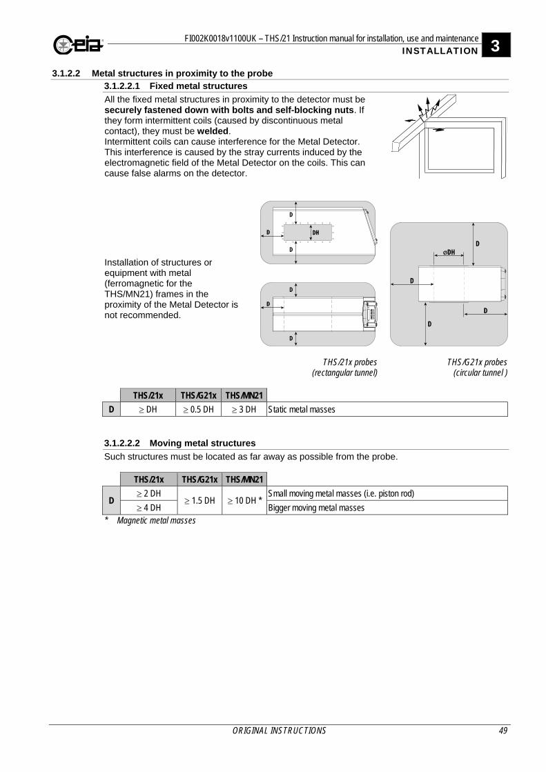
FI002K0018v1100UK – THS/21 Instruction manual for installation, use and maintenance 3 INSTALLATION
ORIGINAL INSTRUCTIONS 49
3.1.2.2 Metal structures in proximity to the probe 3.1.2.2.1 Fixed metal structures
All the fixed metal structures in proximity to the detector must be securely fastened down with bolts and self-blocking nuts. If they form intermittent coils (caused by discontinuous metal contact), they must be welded. Intermittent coils can cause interference for the Metal Detector. This interference is caused by the stray currents induced by the electromagnetic field of the Metal Detector on the coils. This can cause false alarms on the detector.
Installation of structures or equipment with metal (ferromagnetic for the THS/MN21) frames in the proximity of the Metal Detector is not recommended.
THS/21x probes(rectangular tunnel)
THS/G21x probes(circular tunnel )
THS/21x THS/G21x THS/MN21
D DH 0.5 DH 3 DH Static metal masses 3.1.2.2.2 Moving metal structures
Such structures must be located as far away as possible from the probe. THS/21x THS/G21x THS/MN21
D 2 DH
1.5 DH 10 DH * Small moving metal masses (i.e. piston rod)
4 DH Bigger moving metal masses * Magnetic metal masses
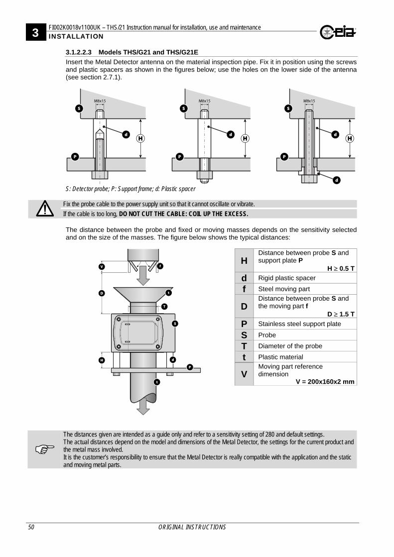
3 FI002K0018v1100UK – THS/21 Instruction manual for installation, use and maintenance INSTALLATION
50 ORIGINAL INSTRUCTIONS
3.1.2.2.3 Models THS/G21 and THS/G21E
Insert the Metal Detector antenna on the material inspection pipe. Fix it in position using the screws and plastic spacers as shown in the figures below; use the holes on the lower side of the antenna (see section 2.7.1).
S: Detector probe; P: Support frame; d: Plastic spacer
Fix the probe cable to the power supply unit so that it cannot oscillate or vibrate.
If the cable is too long, DO NOT CUT THE CABLE: COIL UP THE EXCESS. The distance between the probe and fixed or moving masses depends on the sensitivity selected and on the size of the masses. The figure below shows the typical distances:
H Distance between probe S and support plate P
H 0.5 T
d Rigid plastic spacer
f Steel moving part
D Distance between probe S and the moving part f
D 1.5 T
P Stainless steel support plate
S Probe
T Diameter of the probe
t Plastic material
V Moving part reference dimension
V = 200x160x2 mm
The distances given are intended as a guide only and refer to a sensitivity setting of 280 and default settings. The actual distances depend on the model and dimensions of the Metal Detector, the settings for the current product and the metal mass involved. It is the customer’s responsibility to ensure that the Metal Detector is really compatible with the application and the static and moving metal parts.

FI002K0018v1100UK – THS/21 Instruction manual for installation, use and maintenance 3 INSTALLATION
ORIGINAL INSTRUCTIONS 51
3.1.2.3 Customer conveyor belt 3.1.2.3.1 Load-bearing structure
During assembly the solidity of the load-bearing structure should be borne in mind, in order to ensure that the detector does not oscillate, causing false alarms. The load-bearing structures of the conveyor belt must be stable and not subject to detectable vibration when the belt is moving. For a THS/MN21 the structure of the belt must be in non-magnetic steel (e.g. AISI 316). Welded metal structures are preferable. If the frame, or parts of it, is screwed, insulate each contact between metal parts. Make sure that the metal crossbeams of the frame are as far as possible from the probe opening and, in any case, at no less than the minimum distance required for fixed metal parts.
3.1.2.3.2 Side panels to contain the material in transit
Any side panels near the probe must be made of insulating material (plastic, wood, etc.).
Side panels to contain the material in transit 3.1.2.3.3 Position of the conveyor belt inside the probe
The conveyor belt must run as close as possible to the lower surface of the tunnel. In order to prevent it from accidentally rubbing against the probe it is advisable that it be supported within the probe by means of a sheet of insulating material, which is thick enough to support the weight of the material being transported (approximately 5-20 mm). This is particularly important with long belts which, in addition to requiring extra support, must also be prevented from vibrating. The sheet must not touch the probe (the figure shows a gap of 5-10 mm); if it were to touch the probe it could send vibrations to the probe. In any case, if there is a supporting metal layer for the belt, when it arrives at the probe, it must be interrupted for a distance D, on both sides of the probe.
All models THS/MN21
D 2 DH 4 DH
For products in metalized packs with the THS/21x antenna or contents in aluminium trays with THS/MN21 antennas, the optimum distance of the belt (from the bottom of the probe) is the distance which guarantees that the product passes totally centred on the probe opening. For flat belts, the conveyor belt must pass through the probe in both directions to avoid having to cut and re-join it when substituting the belt.
Position of the conveyor belt inside
the probe
pi: sheet of insulating material; pm: layer of metal material;
n: belt
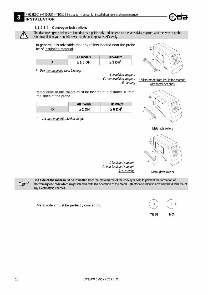
3 FI002K0018v1100UK – THS/21 Instruction manual for installation, use and maintenance INSTALLATION
52 ORIGINAL INSTRUCTIONS
3.1.2.3.4 Conveyor belt rollers
The distances given below are intended as a guide only and depend on the sensitivity required and the type of probe. After installation you should check that the unit operates efficiently. In general, it is advisable that any rollers located near the probe be of insulating material.
All models THS/MN21
D 1,5 DH 3 DH1
1 Use non-magnetic steel bearings.
Rollers made from insulating material
with metal bearings
I: insulated support; C: non-insulated support;
B: bearing
Metal drive or idle rollers must be located at a distance D from the sides of the probe.
All models THS/MN21
D 2 DH 6 DH1 1 Use non-magnetic steel bearings.
Metal idle rollers
Metal drive rollers
I: insulated support; C: non-insulated support;
S: screening
One side of the roller must be insulated from the metal frame of the conveyor belt, to prevent the formation of electromagnetic coils which might interfere with the operation of the Metal Detector and allow in any way the discharge of any electrostatic charges.
Metal rollers must be perfectly concentric.
YES! NO!
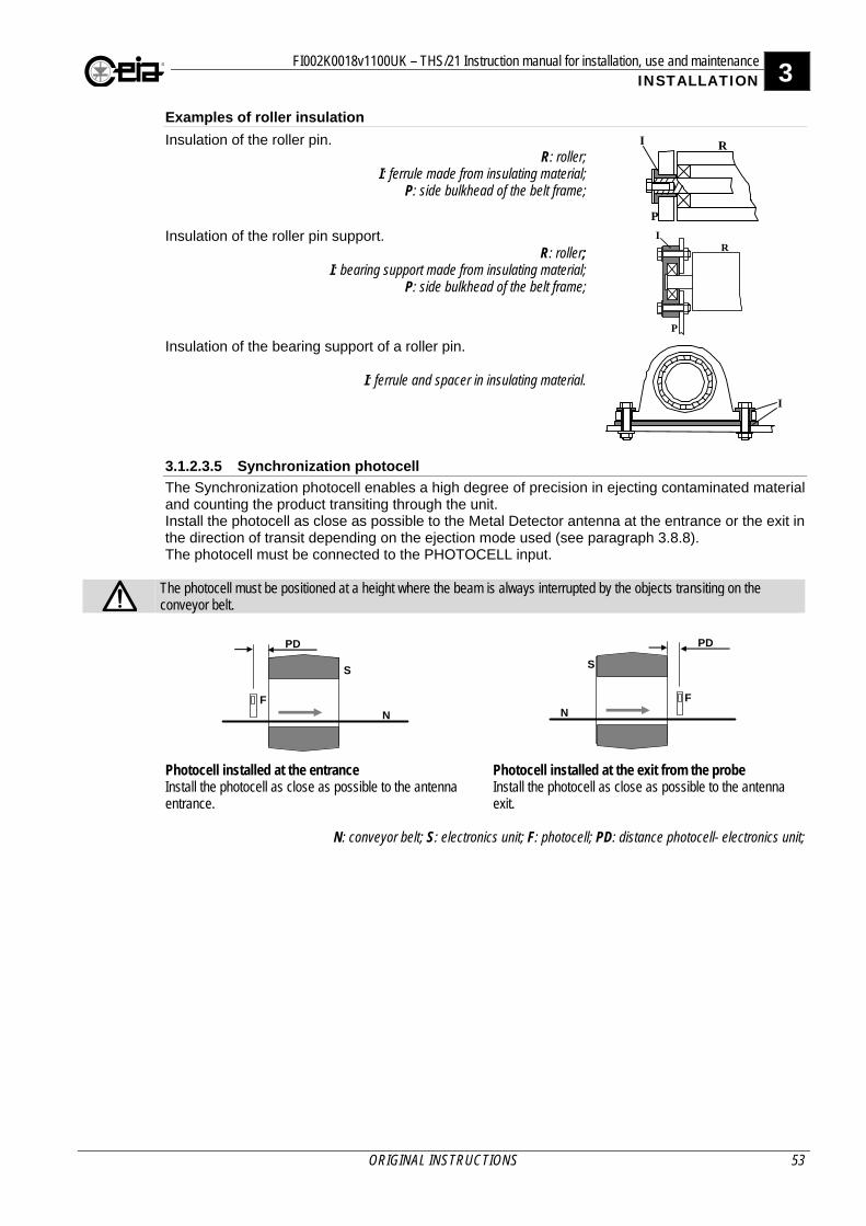
FI002K0018v1100UK – THS/21 Instruction manual for installation, use and maintenance 3 INSTALLATION
ORIGINAL INSTRUCTIONS 53
Examples of roller insulation
Insulation of the roller pin. R: roller;
I: ferrule made from insulating material; P: side bulkhead of the belt frame;
Insulation of the roller pin support. R: roller;
I: bearing support made from insulating material; P: side bulkhead of the belt frame;
Insulation of the bearing support of a roller pin.
I: ferrule and spacer in insulating material.
3.1.2.3.5 Synchronization photocell
The Synchronization photocell enables a high degree of precision in ejecting contaminated material and counting the product transiting through the unit. Install the photocell as close as possible to the Metal Detector antenna at the entrance or the exit in the direction of transit depending on the ejection mode used (see paragraph 3.8.8). The photocell must be connected to the PHOTOCELL input.
The photocell must be positioned at a height where the beam is always interrupted by the objects transiting on the conveyor belt.
F
S
N
PD
F
S
N
PD
Photocell installed at the entrance Install the photocell as close as possible to the antenna entrance.
Photocell installed at the exit from the probe Install the photocell as close as possible to the antenna exit.
N: conveyor belt; S: electronics unit; F: photocell; PD: distance photocell- electronics unit;
I
P
R
I
P
R
I
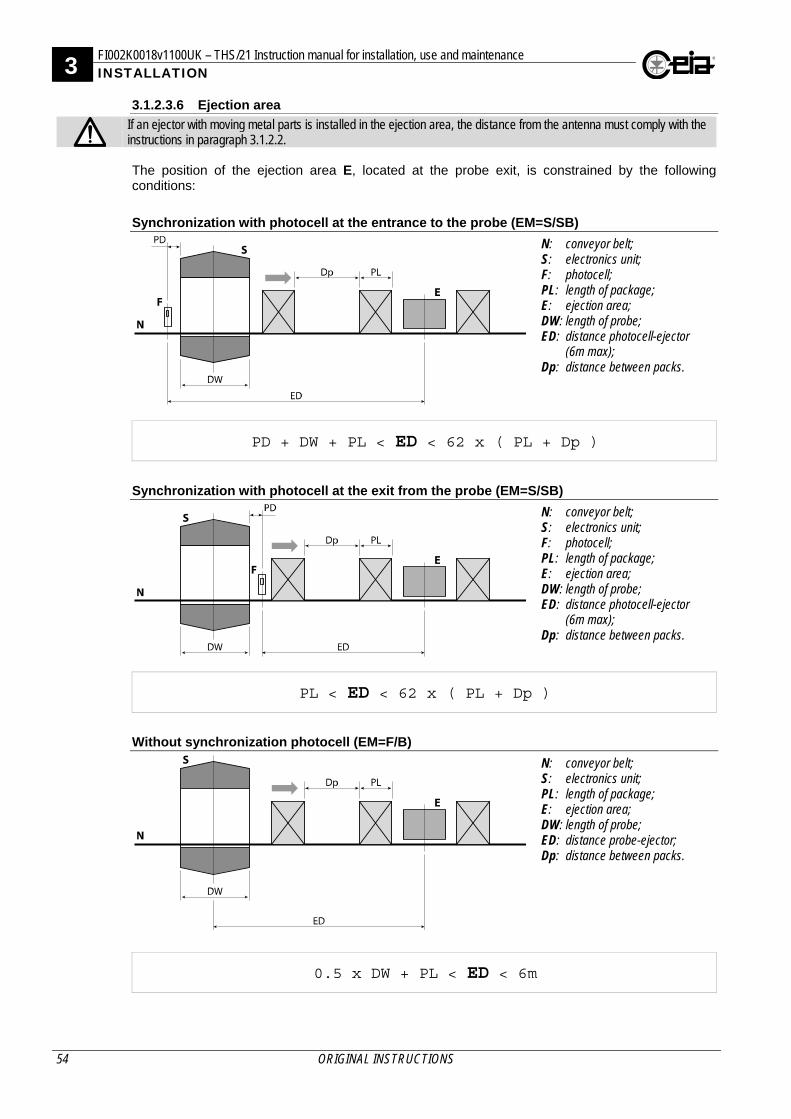
3 FI002K0018v1100UK – THS/21 Instruction manual for installation, use and maintenance INSTALLATION
54 ORIGINAL INSTRUCTIONS
3.1.2.3.6 Ejection area
If an ejector with moving metal parts is installed in the ejection area, the distance from the antenna must comply with the instructions in paragraph 3.1.2.2. The position of the ejection area E, located at the probe exit, is constrained by the following conditions:
Synchronization with photocell at the entrance to the probe (EM=S/SB)
N: conveyor belt; S: electronics unit; F: photocell; PL: length of package; E: ejection area; DW: length of probe; ED: distance photocell-ejector
(6m max); Dp: distance between packs.
PD + DW + PL < ED < 62 x ( PL + Dp )
Synchronization with photocell at the exit from the probe (EM=S/SB)
N: conveyor belt; S: electronics unit; F: photocell; PL: length of package; E: ejection area; DW: length of probe; ED: distance photocell-ejector
(6m max); Dp: distance between packs.
PL < ED < 62 x ( PL + Dp )
Without synchronization photocell (EM=F/B)
N: conveyor belt; S: electronics unit; PL: length of package; E: ejection area; DW: length of probe; ED: distance probe-ejector; Dp: distance between packs.
0.5 x DW + PL < ED < 6m
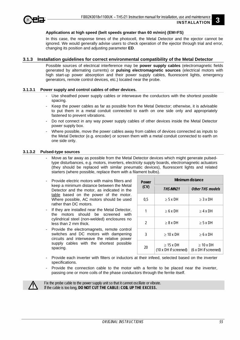
FI002K0018v1100UK – THS/21 Instruction manual for installation, use and maintenance 3 INSTALLATION
ORIGINAL INSTRUCTIONS 55
Applications at high speed (belt speeds greater than 60 m/min) (EM=FS)
In this case, the response times of the photocell, the Metal Detector and the ejector cannot be ignored. We would generally advise users to check operation of the ejector through trial and error, changing its position and adjusting parameter ED.
3.1.3 Installation guidelines for correct environmental compatibility of the Metal Detector Possible sources of electrical interference may be power supply cables (electromagnetic fields generated by alternating currents) or pulsing electromagnetic sources (electrical motors with high start-up power absorption and their power supply cables, fluorescent lights, emergency generators, remote control devices, etc.) located near the probe.
3.1.3.1 Power supply and control cables of other devices.
- Use sheathed power supply cables or interweave the conductors with the shortest possible spacing.
- Keep the power cables as far as possible from the Metal Detector; otherwise, it is advisable to put them in a metal conduit connected to earth on one side only and appropriately fastened to prevent vibrations.
- Do not connect in any way power supply cables of other devices inside the Metal Detector power supply box.
- Where possible, move the power cables away from cables of devices connected as inputs to the Metal Detector (e.g. encoder) or screen them with a metal conduit connected to earth on one side only.
3.1.3.2 Pulsed-type sources
- Move as far away as possible from the Metal Detector devices which might generate pulsed-type disturbances, e.g. motors, inverters, electricity supply boards, electromagnetic actuators (they should be replaced with similar pneumatic devices), fluorescent lights and related starters (where possible, replace them with a filament bulbs).
- Provide electric motors with mains filters and keep a minimum distance between the Metal Detector and the motor, as indicated in the table based on the power of the motor. Where possible, AC motors should be used rather than DC motors.
- If they are installed near the Metal Detector, the motors should be screened with cylindrical steel (non-welded) enclosures no less than 2 mm thick.
- Provide the electromagnets, remote control switches and DC motors with dampening circuits and interweave the relative power supply cables with the shortest possible spacing.
Power (CV)
Minimum distance
THS/MN21 Other THS models
0,5 5 x DH 3 x DH
1 6 x DH 4 x DH
2 8 x DH 5 x DH
3 10 x DH 6 x DH
20 15 x DH (10 x DH if screened)
10 x DH (6 x DH if screened)
- Provide each inverter with filters or inductors at their infeed, selected based on the inverter specifications.
- Provide the connection cable to the motor with a ferrite to be placed near the inverter, passing one or more coils of the phase conductors through the ferrite itself.
Fix the probe cable to the power supply unit so that it cannot oscillate or vibrate. If the cable is too long, DO NOT CUT THE CABLE: COIL UP THE EXCESS.
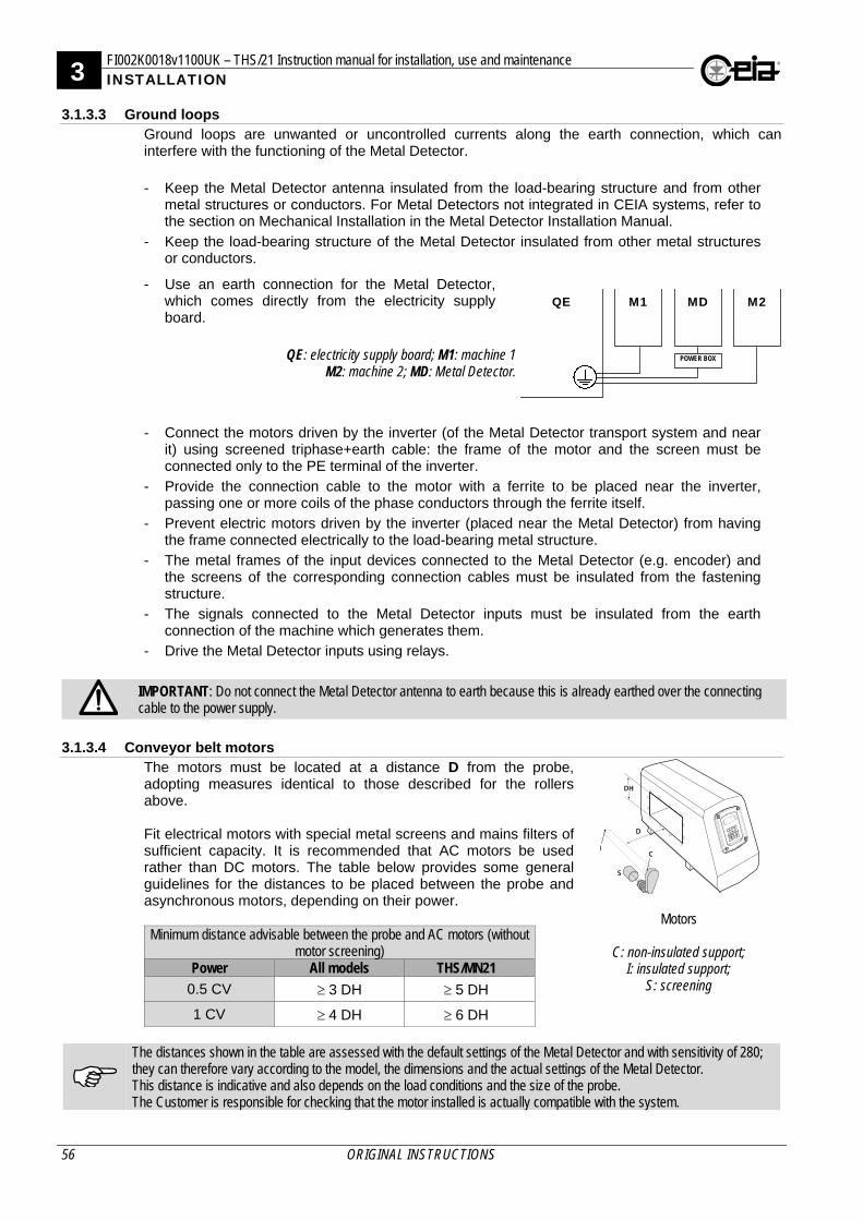
3 FI002K0018v1100UK – THS/21 Instruction manual for installation, use and maintenance INSTALLATION
56 ORIGINAL INSTRUCTIONS
3.1.3.3 Ground loops Ground loops are unwanted or uncontrolled currents along the earth connection, which can interfere with the functioning of the Metal Detector.
- Keep the Metal Detector antenna insulated from the load-bearing structure and from other metal structures or conductors. For Metal Detectors not integrated in CEIA systems, refer to the section on Mechanical Installation in the Metal Detector Installation Manual.
- Keep the load-bearing structure of the Metal Detector insulated from other metal structures or conductors.
- Use an earth connection for the Metal Detector, which comes directly from the electricity supply board.
QE: electricity supply board; M1: machine 1
M2: machine 2; MD: Metal Detector.
QE M1 M2 MD
POWER BOX
- Connect the motors driven by the inverter (of the Metal Detector transport system and near it) using screened triphase+earth cable: the frame of the motor and the screen must be connected only to the PE terminal of the inverter.
- Provide the connection cable to the motor with a ferrite to be placed near the inverter, passing one or more coils of the phase conductors through the ferrite itself.
- Prevent electric motors driven by the inverter (placed near the Metal Detector) from having the frame connected electrically to the load-bearing metal structure.
- The metal frames of the input devices connected to the Metal Detector (e.g. encoder) and the screens of the corresponding connection cables must be insulated from the fastening structure.
- The signals connected to the Metal Detector inputs must be insulated from the earth connection of the machine which generates them.
- Drive the Metal Detector inputs using relays.
IMPORTANT: Do not connect the Metal Detector antenna to earth because this is already earthed over the connecting cable to the power supply.
3.1.3.4 Conveyor belt motors The motors must be located at a distance D from the probe, adopting measures identical to those described for the rollers above.
Fit electrical motors with special metal screens and mains filters of sufficient capacity. It is recommended that AC motors be used rather than DC motors. The table below provides some general guidelines for the distances to be placed between the probe and asynchronous motors, depending on their power.
Minimum distance advisable between the probe and AC motors (without
motor screening) Power All models THS/MN21
0.5 CV 3 DH 5 DH
1 CV 4 DH 6 DH
Motors
C: non-insulated support; I: insulated support;
S: screening
The distances shown in the table are assessed with the default settings of the Metal Detector and with sensitivity of 280; they can therefore vary according to the model, the dimensions and the actual settings of the Metal Detector. This distance is indicative and also depends on the load conditions and the size of the probe. The Customer is responsible for checking that the motor installed is actually compatible with the system.
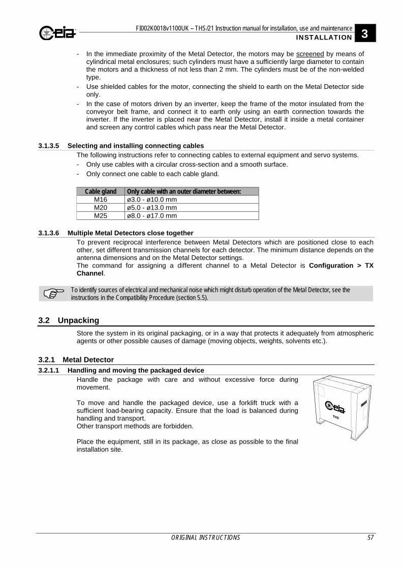
FI002K0018v1100UK – THS/21 Instruction manual for installation, use and maintenance 3 INSTALLATION
ORIGINAL INSTRUCTIONS 57
- In the immediate proximity of the Metal Detector, the motors may be screened by means of cylindrical metal enclosures; such cylinders must have a sufficiently large diameter to contain the motors and a thickness of not less than 2 mm. The cylinders must be of the non-welded type.
- Use shielded cables for the motor, connecting the shield to earth on the Metal Detector side only.
- In the case of motors driven by an inverter, keep the frame of the motor insulated from the conveyor belt frame, and connect it to earth only using an earth connection towards the inverter. If the inverter is placed near the Metal Detector, install it inside a metal container and screen any control cables which pass near the Metal Detector.
3.1.3.5 Selecting and installing connecting cables
The following instructions refer to connecting cables to external equipment and servo systems. - Only use cables with a circular cross-section and a smooth surface.
- Only connect one cable to each cable gland.
Cable gland Only cable with an outer diameter between:
M16 ø3.0 - ø10.0 mm M20 ø5.0 - ø13.0 mm M25 ø8.0 - ø17.0 mm
3.1.3.6 Multiple Metal Detectors close together
To prevent reciprocal interference between Metal Detectors which are positioned close to each other, set different transmission channels for each detector. The minimum distance depends on the antenna dimensions and on the Metal Detector settings. The command for assigning a different channel to a Metal Detector is Configuration > TX Channel.
To identify sources of electrical and mechanical noise which might disturb operation of the Metal Detector, see the instructions in the Compatibility Procedure (section 5.5).
3.2 Unpacking
Store the system in its original packaging, or in a way that protects it adequately from atmospheric agents or other possible causes of damage (moving objects, weights, solvents etc.).
3.2.1 Metal Detector
3.2.1.1 Handling and moving the packaged device Handle the package with care and without excessive force during movement. To move and handle the packaged device, use a forklift truck with a sufficient load-bearing capacity. Ensure that the load is balanced during handling and transport. Other transport methods are forbidden. Place the equipment, still in its package, as close as possible to the final installation site.
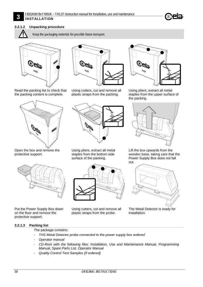
3 FI002K0018v1100UK – THS/21 Instruction manual for installation, use and maintenance INSTALLATION
58 ORIGINAL INSTRUCTIONS
3.2.1.2 Unpacking procedure
Keep the packaging materials for possible future transport.
Read the packing list to check that the packing content is complete.
Using cutters, cut and remove all plastic straps from the packing.
Using pliers, extract all metal staples from the upper surface of the packing.
Open the box and remove the protective support.
Using pliers, extract all metal staples from the bottom side surface of the packing.
Lift the box upwards from the wooden base, taking care that the Power Supply Box does not fall out.
Put the Power Supply Box down on the floor and remove the protective support.
Using cutters, cut and remove all plastic straps from the probe.
The Metal Detector is ready for installation.
3.2.1.3 Packing list
The package contains:
- THS Metal Detector probe connected to the power supply box ordered
- Operator manual
- CD-Rom with the following files: Installation, Use and Maintenance Manual, Programming Manual, Spare Parts List, Operator Manual
- Quality Control Test Samples (if ordered)
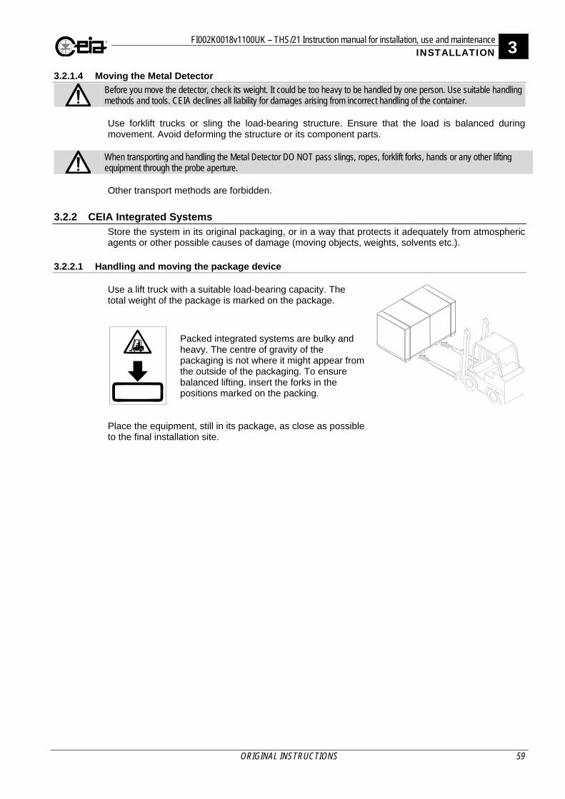
FI002K0018v1100UK – THS/21 Instruction manual for installation, use and maintenance 3 INSTALLATION
ORIGINAL INSTRUCTIONS 59
3.2.1.4 Moving the Metal Detector
Before you move the detector, check its weight. It could be too heavy to be handled by one person. Use suitable handling methods and tools. CEIA declines all liability for damages arising from incorrect handling of the container. Use forklift trucks or sling the load-bearing structure. Ensure that the load is balanced during movement. Avoid deforming the structure or its component parts.
When transporting and handling the Metal Detector DO NOT pass slings, ropes, forklift forks, hands or any other lifting equipment through the probe aperture. Other transport methods are forbidden.
3.2.2 CEIA Integrated Systems Store the system in its original packaging, or in a way that protects it adequately from atmospheric agents or other possible causes of damage (moving objects, weights, solvents etc.).
3.2.2.1 Handling and moving the package device
Use a lift truck with a suitable load-bearing capacity. The total weight of the package is marked on the package.
Packed integrated systems are bulky and heavy. The centre of gravity of the packaging is not where it might appear from the outside of the packaging. To ensure balanced lifting, insert the forks in the positions marked on the packing.
Place the equipment, still in its package, as close as possible to the final installation site.
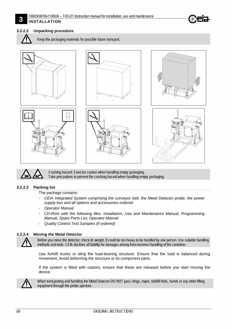
3 FI002K0018v1100UK – THS/21 Instruction manual for installation, use and maintenance INSTALLATION
60 ORIGINAL INSTRUCTIONS
3.2.2.2 Unpacking procedure
Keep the packaging materials for possible future transport.
Crushing hazard. Exercise caution when handling empty packaging. Take precautions to prevent the crushing hazard when handling empty packaging.
3.2.2.3 Packing list
The package contains:
- CEIA Integrated System comprising the conveyor belt, the Metal Detector probe, the power supply box and all options and accessories ordered
- Operator Manual
- CD-Rom with the following files: Installation, Use and Maintenance Manual, Programming Manual, Spare Parts List, Operator Manual
- Quality Control Test Samples (if ordered)
3.2.2.4 Moving the Metal Detector
Before you move the detector, check its weight. It could be too heavy to be handled by one person. Use suitable handling methods and tools. CEIA declines all liability for damages arising from incorrect handling of the container. Use forklift trucks or sling the load-bearing structure. Ensure that the load is balanced during movement. Avoid deforming the structure or its component parts. If the system is fitted with castors, ensure that these are released before you start moving the device.
When transporting and handling the Metal Detector DO NOT pass slings, ropes, forklift forks, hands or any other lifting equipment through the probe aperture.
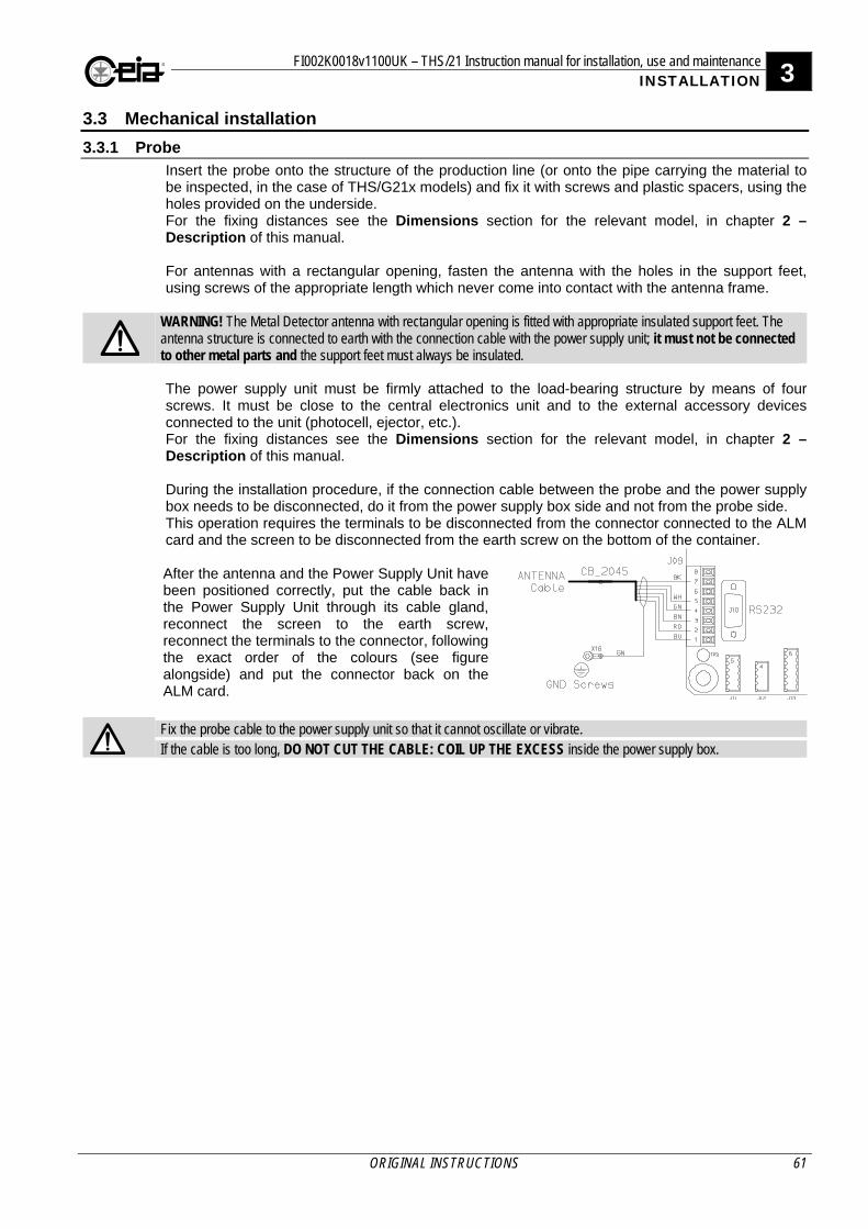
FI002K0018v1100UK – THS/21 Instruction manual for installation, use and maintenance 3 INSTALLATION
ORIGINAL INSTRUCTIONS 61
3.3 Mechanical installation
3.3.1 Probe Insert the probe onto the structure of the production line (or onto the pipe carrying the material to be inspected, in the case of THS/G21x models) and fix it with screws and plastic spacers, using the holes provided on the underside. For the fixing distances see the Dimensions section for the relevant model, in chapter 2 – Description of this manual. For antennas with a rectangular opening, fasten the antenna with the holes in the support feet, using screws of the appropriate length which never come into contact with the antenna frame.
WARNING! The Metal Detector antenna with rectangular opening is fitted with appropriate insulated support feet. The antenna structure is connected to earth with the connection cable with the power supply unit; it must not be connected to other metal parts and the support feet must always be insulated. The power supply unit must be firmly attached to the load-bearing structure by means of four screws. It must be close to the central electronics unit and to the external accessory devices connected to the unit (photocell, ejector, etc.). For the fixing distances see the Dimensions section for the relevant model, in chapter 2 – Description of this manual. During the installation procedure, if the connection cable between the probe and the power supply box needs to be disconnected, do it from the power supply box side and not from the probe side. This operation requires the terminals to be disconnected from the connector connected to the ALM card and the screen to be disconnected from the earth screw on the bottom of the container. After the antenna and the Power Supply Unit have been positioned correctly, put the cable back in the Power Supply Unit through its cable gland, reconnect the screen to the earth screw, reconnect the terminals to the connector, following the exact order of the colours (see figure alongside) and put the connector back on the ALM card.
Fix the probe cable to the power supply unit so that it cannot oscillate or vibrate. If the cable is too long, DO NOT CUT THE CABLE: COIL UP THE EXCESS inside the power supply box.
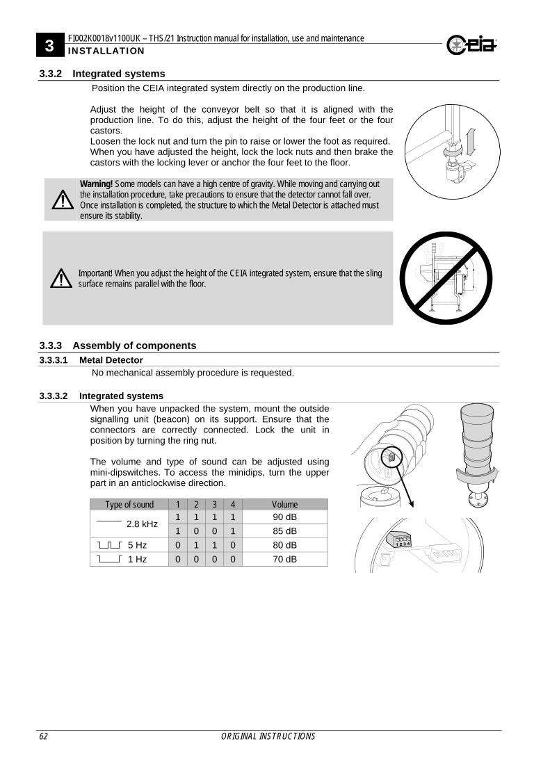
3 FI002K0018v1100UK – THS/21 Instruction manual for installation, use and maintenance INSTALLATION
62 ORIGINAL INSTRUCTIONS
3.3.2 Integrated systems Position the CEIA integrated system directly on the production line. Adjust the height of the conveyor belt so that it is aligned with the production line. To do this, adjust the height of the four feet or the four castors. Loosen the lock nut and turn the pin to raise or lower the foot as required. When you have adjusted the height, lock the lock nuts and then brake the castors with the locking lever or anchor the four feet to the floor.
Warning! Some models can have a high centre of gravity. While moving and carrying out the installation procedure, take precautions to ensure that the detector cannot fall over. Once installation is completed, the structure to which the Metal Detector is attached must ensure its stability.
Important! When you adjust the height of the CEIA integrated system, ensure that the sling surface remains parallel with the floor.
3.3.3 Assembly of components
3.3.3.1 Metal Detector No mechanical assembly procedure is requested.
3.3.3.2 Integrated systems When you have unpacked the system, mount the outside signalling unit (beacon) on its support. Ensure that the connectors are correctly connected. Lock the unit in position by turning the ring nut.
The volume and type of sound can be adjusted using mini-dipswitches. To access the minidips, turn the upper part in an anticlockwise direction.
Type of sound 1 2 3 4 Volume
2.8 kHz 1 1 1 1 90 dB
1 0 0 1 85 dB
5 Hz 0 1 1 0 80 dB
1 Hz 0 0 0 0 70 dB
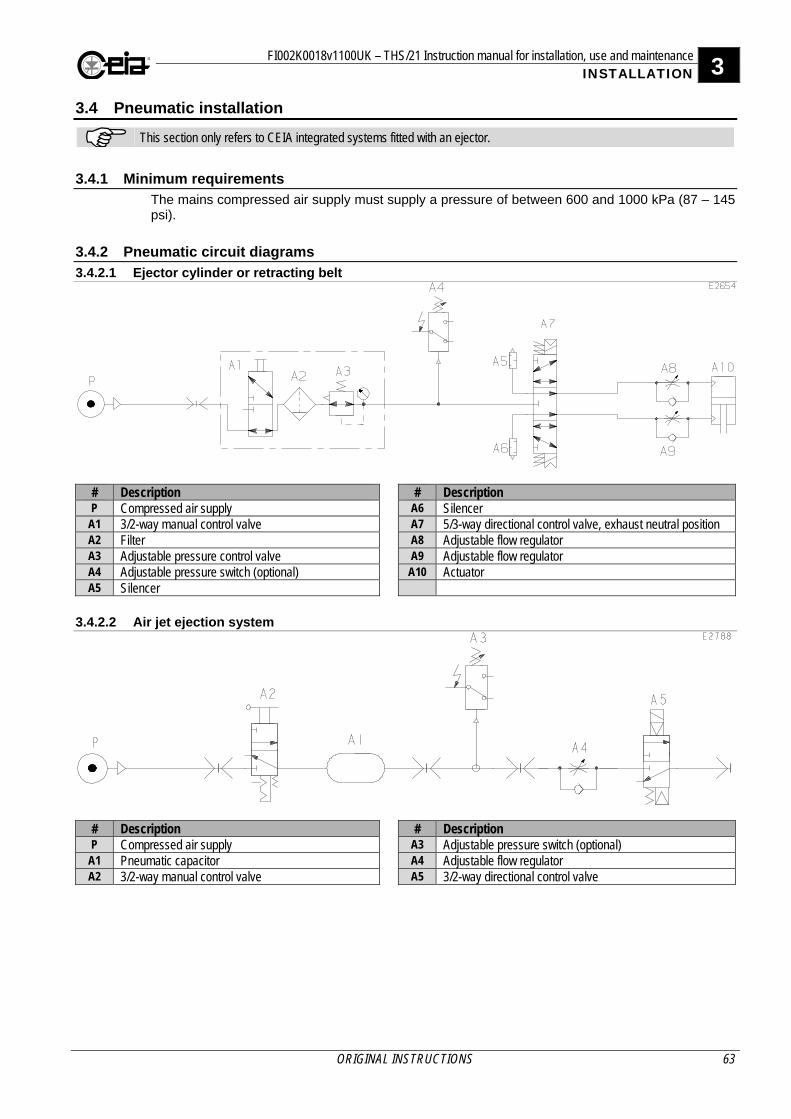
FI002K0018v1100UK – THS/21 Instruction manual for installation, use and maintenance 3 INSTALLATION
ORIGINAL INSTRUCTIONS 63
3.4 Pneumatic installation
This section only refers to CEIA integrated systems fitted with an ejector.
3.4.1 Minimum requirements The mains compressed air supply must supply a pressure of between 600 and 1000 kPa (87 – 145 psi).
3.4.2 Pneumatic circuit diagrams
3.4.2.1 Ejector cylinder or retracting belt
# Description # Description P Compressed air supply A6 Silencer
A1 3/2-way manual control valve A7 5/3-way directional control valve, exhaust neutral position A2 Filter A8 Adjustable flow regulator A3 Adjustable pressure control valve A9 Adjustable flow regulator A4 Adjustable pressure switch (optional) A10 Actuator A5 Silencer
3.4.2.2 Air jet ejection system
# Description # Description P Compressed air supply A3 Adjustable pressure switch (optional)
A1 Pneumatic capacitor A4 Adjustable flow regulator A2 3/2-way manual control valve A5 3/2-way directional control valve
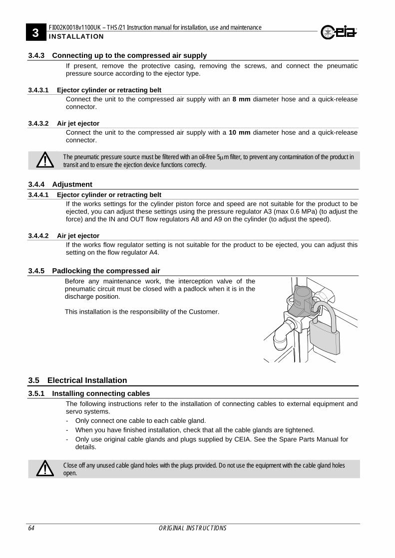
3 FI002K0018v1100UK – THS/21 Instruction manual for installation, use and maintenance INSTALLATION
64 ORIGINAL INSTRUCTIONS
3.4.3 Connecting up to the compressed air supply If present, remove the protective casing, removing the screws, and connect the pneumatic pressure source according to the ejector type.
3.4.3.1 Ejector cylinder or retracting belt Connect the unit to the compressed air supply with an 8 mm diameter hose and a quick-release connector.
3.4.3.2 Air jet ejector Connect the unit to the compressed air supply with a 10 mm diameter hose and a quick-release connector.
The pneumatic pressure source must be filtered with an oil-free 5m filter, to prevent any contamination of the product in transit and to ensure the ejection device functions correctly.
3.4.4 Adjustment
3.4.4.1 Ejector cylinder or retracting belt If the works settings for the cylinder piston force and speed are not suitable for the product to be ejected, you can adjust these settings using the pressure regulator A3 (max 0.6 MPa) (to adjust the force) and the IN and OUT flow regulators A8 and A9 on the cylinder (to adjust the speed).
3.4.4.2 Air jet ejector If the works flow regulator setting is not suitable for the product to be ejected, you can adjust this setting on the flow regulator A4.
3.4.5 Padlocking the compressed air Before any maintenance work, the interception valve of the pneumatic circuit must be closed with a padlock when it is in the discharge position. This installation is the responsibility of the Customer.
3.5 Electrical Installation
3.5.1 Installing connecting cables The following instructions refer to the installation of connecting cables to external equipment and servo systems. - Only connect one cable to each cable gland.
- When you have finished installation, check that all the cable glands are tightened.
- Only use original cable glands and plugs supplied by CEIA. See the Spare Parts Manual for details.
Close off any unused cable gland holes with the plugs provided. Do not use the equipment with the cable gland holes open.
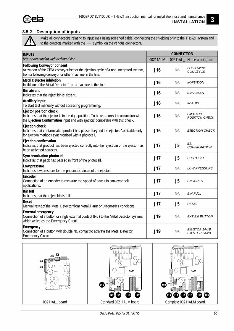
FI002K0018v1100UK – THS/21 Instruction manual for installation, use and maintenance 3 INSTALLATION
ORIGINAL INSTRUCTIONS 65
3.5.2 Description of inputs
Make all connections relating to input lines using screened cable, connecting the shielding only to the THS/21 system and to the contacts marked with the symbol on the various connectors.
INPUTS Use or description with activated line
CONNECTION
00211ALM 00211AL_ Name on diagram
Following Conveyor consent Activation of the CEIA conveyor belt or the ejection cycle of a non-integrated system, from a following conveyor or other machine in the line.
J16 N/A FOLLOWING CONVEYOR
Metal Detector inhibition Inhibition of the Metal Detector from a machine in the line. J16 N/A INHIBITION
Bin absent Indicates that the reject bin is absent. J16 N/A BIN ABSENT
Auxiliary input To start test manually without accessing programming. J16 N/A IN AUX1
Ejector position check Indicates that the ejector is in the right position. To be used only in conjunction with the Ejection Confirmation input and with ejectors compatible with this check.
J16 N/A EJECTOR POSITION CHECK
Ejection check Indicates that contaminated product has passed beyond the ejector. Applicable only for ejection methods synchronized with a photocell.
J16 N/A EJECTION CHECK
Ejection confirmation Indicates that product has been ejected correctly into the reject bin or the ejector has been activated correctly.
J17 J5 EJ. CONFIRMATION
Synchronization photocell Indicates that pack has passed in front of the photocell. J17 J5 PHOTOCELL
Low pressure Indicates low pressure for the pneumatic circuit of the ejector. J17 N/A LOW PRESSURE
Encoder Connection of an encoder to measure the speed of transit in conveyor belt applications.
J17 J5 ENCODER
Bin full Indicates that the reject bin is full. J17 N/A BIN FULL
Reset Manual reset of the Metal Detector from Metal Alarm or Diagnostics conditions. J17 J5 RESET
External emergency Connection of a button or single external contact (NC) to the Metal Detector system, which activates the Emergency Circuit.
J19 N/A EXT EM BUTTON
Emergency Connection of a button with double NC contact to activate the Metal Detector Emergency Circuit.
J19 N/A EM STOP 1A/1B EM STOP 2A/2B
00211AL_ board Standard 00211ALM board Complete 00211ALM board
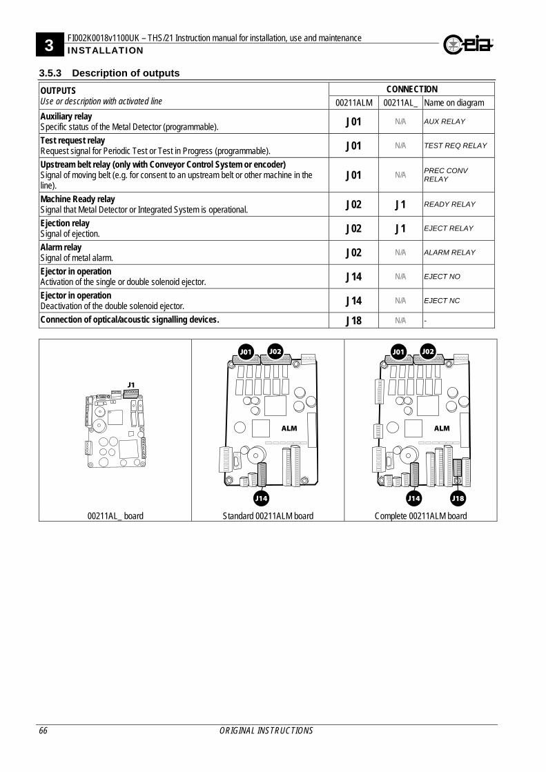
3 FI002K0018v1100UK – THS/21 Instruction manual for installation, use and maintenance INSTALLATION
66 ORIGINAL INSTRUCTIONS
3.5.3 Description of outputs
OUTPUTS Use or description with activated line
CONNECTION
00211ALM 00211AL_ Name on diagram
Auxiliary relay Specific status of the Metal Detector (programmable). J01 N/A AUX RELAY
Test request relay Request signal for Periodic Test or Test in Progress (programmable). J01 N/A TEST REQ RELAY
Upstream belt relay (only with Conveyor Control System or encoder) Signal of moving belt (e.g. for consent to an upstream belt or other machine in the line).
J01 N/A PREC CONV RELAY
Machine Ready relay Signal that Metal Detector or Integrated System is operational. J02 J1 READY RELAY
Ejection relay Signal of ejection. J02 J1 EJECT RELAY
Alarm relay Signal of metal alarm. J02 N/A ALARM RELAY
Ejector in operation Activation of the single or double solenoid ejector. J14 N/A EJECT NO
Ejector in operation Deactivation of the double solenoid ejector. J14 N/A EJECT NC
Connection of optical/acoustic signalling devices. J18 N/A -
00211AL_ board Standard 00211ALM board Complete 00211ALM board
FI002K0018v1100UK – THS/21 Instruction manual for installation, use and maintenance 3 INSTALLATION
ORIGINAL INSTRUCTIONS 67
3.5.4 Description of I/O interfaces
I/O INTERFACES Description
CONNECTION
00211ALM 00211AL_ Name on diagram
RS232 Serial interface (sub-D 9p female) Connection for serial printer. Connection for personal computer, to save parameters and any firmware updates. Deactivated when Bluetooth connection is active.
J10 J3 -
Barcode reader Connection to a barcode reader, upstream of the Metal Detector, for automatic selection of the detection parameters in accordance with the barcode of the product in transit.
J11 N/A -
Auxiliary RS232 serial interface Typical use with remote terminal emulation software. J12 J4 -
RCU Remote Control Unit Connection of a remote control unit RCU. J13 J2 -
00211AL_ board Standard 00211ALM board Complete 00211ALM board
3.5.5 Communication connections
3.5.5.1 RS232 serial port connections The RS232 serial port is used by the CEIA MD Scope program, available on request. A standard serial communication program (like Windows Hyperterminal) can also be used. Read the Programming Manual for further information.
3.5.5.2 Bluetooth communication The programming can be also performed through a Bluetooth connection, using standard communication software (such as Windows HyperTerminal) or through the CEIA MDScope program, available on request. Read the Programming Manual for further information.
3.5.5.3 Ethernet / WiFi connections (on request, with IXC card) Read the Programming Manual for further information.
3 FI002K0018v1100UK – THS/21 Instruction manual for installation, use and maintenance INSTALLATION
68 ORIGINAL INSTRUCTIONS
3.5.6 Connection to the Production Line emergency circuit If the CEIA integrated system is connected in line with other machines, the emergency buttons must be connected in such a way that activating one emergency button on the line stops all the machines on that line. Inside each emergency button of CEIA Integrated Systems, there is an unused contact which must be connected by the installer so that, when pressed, it stops the line on which the Metal Detector is located.
Unscrew and remove the cover of the emergency
button, to access the contacts inside
Release the pre-pressed hole on the emergency
button container
Insert an M20 cable gland and lock on the hole
Insert a cable of the right size for the gland, so that the
degree of protection is guaranteed, and connect the terminals to the free contact
The emergency circuit of the production line to which the Metal Detector belongs must also provide the CEIA Integrated System with a clean contact, normally closed, which opens if the emergency button is pressed, allowing the CEIA conveyor belt to be stopped. This contact must be connected to terminals 3 and 4 of connector J19 on the ALM card (see the electrical diagram).
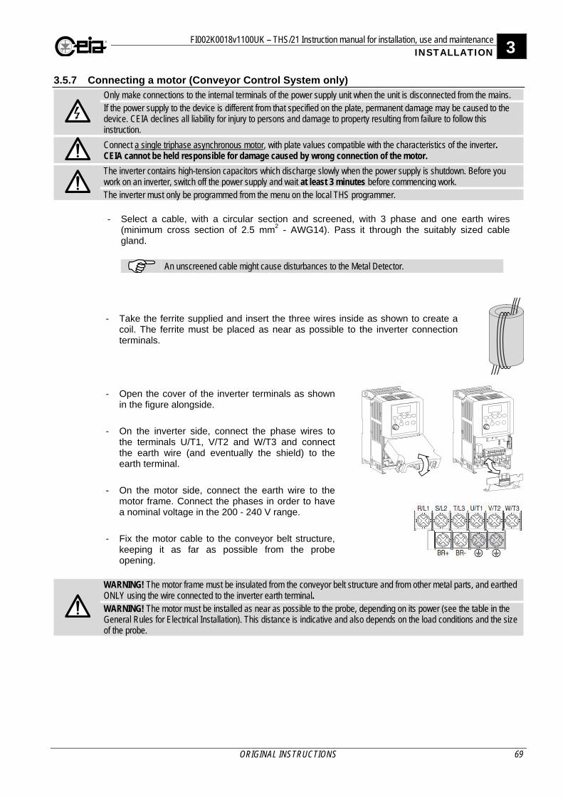
FI002K0018v1100UK – THS/21 Instruction manual for installation, use and maintenance 3 INSTALLATION
ORIGINAL INSTRUCTIONS 69
3.5.7 Connecting a motor (Conveyor Control System only)
Only make connections to the internal terminals of the power supply unit when the unit is disconnected from the mains. If the power supply to the device is different from that specified on the plate, permanent damage may be caused to the device. CEIA declines all liability for injury to persons and damage to property resulting from failure to follow this instruction.
Connect a single triphase asynchronous motor, with plate values compatible with the characteristics of the inverter. CEIA cannot be held responsible for damage caused by wrong connection of the motor.
The inverter contains high-tension capacitors which discharge slowly when the power supply is shutdown. Before you work on an inverter, switch off the power supply and wait at least 3 minutes before commencing work. The inverter must only be programmed from the menu on the local THS programmer.
- Select a cable, with a circular section and screened, with 3 phase and one earth wires (minimum cross section of 2.5 mm2 - AWG14). Pass it through the suitably sized cable gland.
An unscreened cable might cause disturbances to the Metal Detector.
- Take the ferrite supplied and insert the three wires inside as shown to create a coil. The ferrite must be placed as near as possible to the inverter connection terminals.
- Open the cover of the inverter terminals as shown in the figure alongside.
- On the inverter side, connect the phase wires to the terminals U/T1, V/T2 and W/T3 and connect the earth wire (and eventually the shield) to the earth terminal.
- On the motor side, connect the earth wire to the motor frame. Connect the phases in order to have a nominal voltage in the 200 - 240 V range.
- Fix the motor cable to the conveyor belt structure, keeping it as far as possible from the probe opening.
WARNING! The motor frame must be insulated from the conveyor belt structure and from other metal parts, and earthed ONLY using the wire connected to the inverter earth terminal. WARNING! The motor must be installed as near as possible to the probe, depending on its power (see the table in the General Rules for Electrical Installation). This distance is indicative and also depends on the load conditions and the size of the probe.
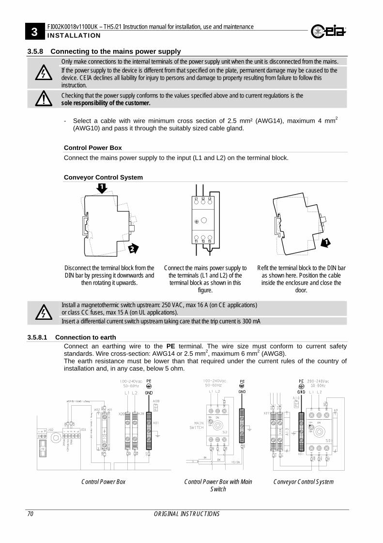
3 FI002K0018v1100UK – THS/21 Instruction manual for installation, use and maintenance INSTALLATION
70 ORIGINAL INSTRUCTIONS
3.5.8 Connecting to the mains power supply
Only make connections to the internal terminals of the power supply unit when the unit is disconnected from the mains. If the power supply to the device is different from that specified on the plate, permanent damage may be caused to the device. CEIA declines all liability for injury to persons and damage to property resulting from failure to follow this instruction.
Checking that the power supply conforms to the values specified above and to current regulations is the sole responsibility of the customer.
- Select a cable with wire minimum cross section of 2.5 mm² (AWG14), maximum 4 mm2
(AWG10) and pass it through the suitably sized cable gland.
Control Power Box
Connect the mains power supply to the input (L1 and L2) on the terminal block.
Conveyor Control System
Disconnect the terminal block from the DIN bar by pressing it downwards and
then rotating it upwards.
Connect the mains power supply to the terminals (L1 and L2) of the terminal block as shown in this
figure.
Refit the terminal block to the DIN bar as shown here. Position the cable inside the enclosure and close the
door.
Install a magnetothermic switch upstream: 250 VAC, max 16 A (on CE applications) or class CC fuses, max 15 A (on UL applications). Insert a differential current switch upstream taking care that the trip current is 300 mA
3.5.8.1 Connection to earth
Connect an earthing wire to the PE terminal. The wire size must conform to current safety standards. Wire cross-section: AWG14 or 2.5 mm2, maximum 6 mm2 (AWG8). The earth resistance must be lower than that required under the current rules of the country of installation and, in any case, below 5 ohm.
Control Power Box
Control Power Box with Main
Switch
Conveyor Control System

FI002K0018v1100UK – THS/21 Instruction manual for installation, use and maintenance 3 INSTALLATION
ORIGINAL INSTRUCTIONS 71
3.5.8.2 Power Switch
On the Conveyor Control System model, the On/Off switch is located on the power supply unit cover; in the case of the Control Power Box, an external switch must be fitted. If necessary, the Conveyor Control System switch can be locked in the OFF position with a padlock. When the switch is in the OFF position, depress the central part of the switch and insert the padlock in the slot created. In this way the switch cannot turn to the ON position until the padlock has been removed.
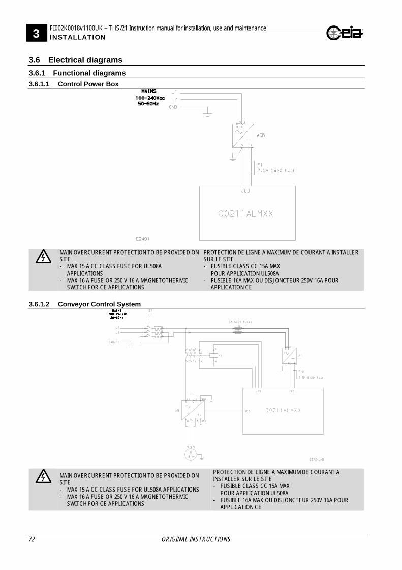
3 FI002K0018v1100UK – THS/21 Instruction manual for installation, use and maintenance INSTALLATION
72 ORIGINAL INSTRUCTIONS
3.6 Electrical diagrams
3.6.1 Functional diagrams
3.6.1.1 Control Power Box
MAIN OVERCURRENT PROTECTION TO BE PROVIDED ON SITE - MAX 15 A CC CLASS FUSE FOR UL508A
APPLICATIONS - MAX 16 A FUSE OR 250 V 16 A MAGNETOTHERMIC
SWITCH FOR CE APPLICATIONS
PROTECTION DE LIGNE A MAXIMUM DE COURANT A INSTALLER SUR LE SITE - FUSIBLE CLASS CC 15A MAX
POUR APPLICATION UL508A - FUSIBLE 16A MAX OU DISJONCTEUR 250V 16A POUR
APPLICATION CE
3.6.1.2 Conveyor Control System
MAIN OVERCURRENT PROTECTION TO BE PROVIDED ON SITE - MAX 15 A CC CLASS FUSE FOR UL508A APPLICATIONS - MAX 16 A FUSE OR 250 V 16 A MAGNETOTHERMIC
SWITCH FOR CE APPLICATIONS
PROTECTION DE LIGNE A MAXIMUM DE COURANT A INSTALLER SUR LE SITE - FUSIBLE CLASS CC 15A MAX
POUR APPLICATION UL508A - FUSIBLE 16A MAX OU DISJONCTEUR 250V 16A POUR
APPLICATION CE
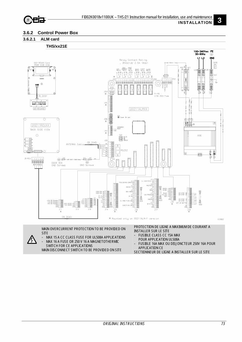
FI002K0018v1100UK – THS/21 Instruction manual for installation, use and maintenance 3 INSTALLATION
ORIGINAL INSTRUCTIONS 73
3.6.2 Control Power Box
3.6.2.1 ALM card
THS/xx21E
MAIN OVERCURRENT PROTECTION TO BE PROVIDED ON SITE - MAX 15 A CC CLASS FUSE FOR UL508A APPLICATIONS - MAX 16 A FUSE OR 250 V 16 A MAGNETOTHERMIC
SWITCH FOR CE APPLICATIONS MAIN DISCONNECT SWITCH TO BE PROVIDED ON SITE
PROTECTION DE LIGNE A MAXIMUM DE COURANT A INSTALLER SUR LE SITE - FUSIBLE CLASS CC 15A MAX
POUR APPLICATION UL508A - FUSIBLE 16A MAX OU DISJONCTEUR 250V 16A POUR
APPLICATION CE SECTIONNEUR DE LIGNE A INSTALLER SUR LE SITE
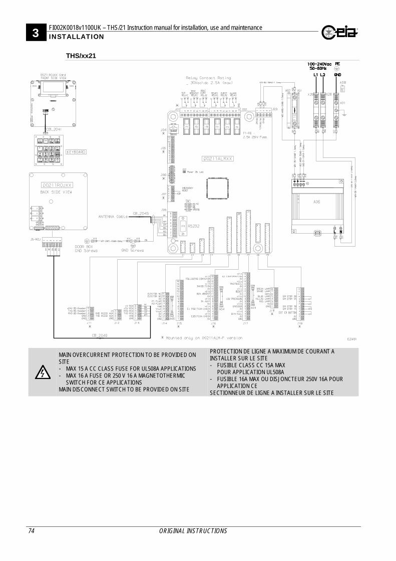
3 FI002K0018v1100UK – THS/21 Instruction manual for installation, use and maintenance INSTALLATION
74 ORIGINAL INSTRUCTIONS
THS/xx21
MAIN OVERCURRENT PROTECTION TO BE PROVIDED ON SITE - MAX 15 A CC CLASS FUSE FOR UL508A APPLICATIONS - MAX 16 A FUSE OR 250 V 16 A MAGNETOTHERMIC
SWITCH FOR CE APPLICATIONS MAIN DISCONNECT SWITCH TO BE PROVIDED ON SITE
PROTECTION DE LIGNE A MAXIMUM DE COURANT A INSTALLER SUR LE SITE - FUSIBLE CLASS CC 15A MAX
POUR APPLICATION UL508A - FUSIBLE 16A MAX OU DISJONCTEUR 250V 16A POUR
APPLICATION CE SECTIONNEUR DE LIGNE A INSTALLER SUR LE SITE
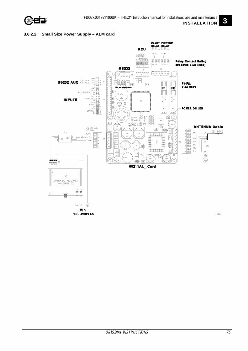
FI002K0018v1100UK – THS/21 Instruction manual for installation, use and maintenance 3 INSTALLATION
ORIGINAL INSTRUCTIONS 75
3.6.2.2 Small Size Power Supply – ALM card
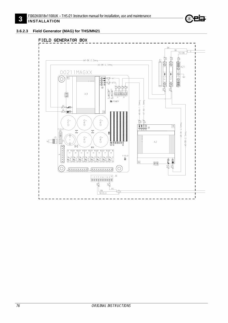
3 FI002K0018v1100UK – THS/21 Instruction manual for installation, use and maintenance INSTALLATION
76 ORIGINAL INSTRUCTIONS
3.6.2.3 Field Generator (MAG) for THS/MN21
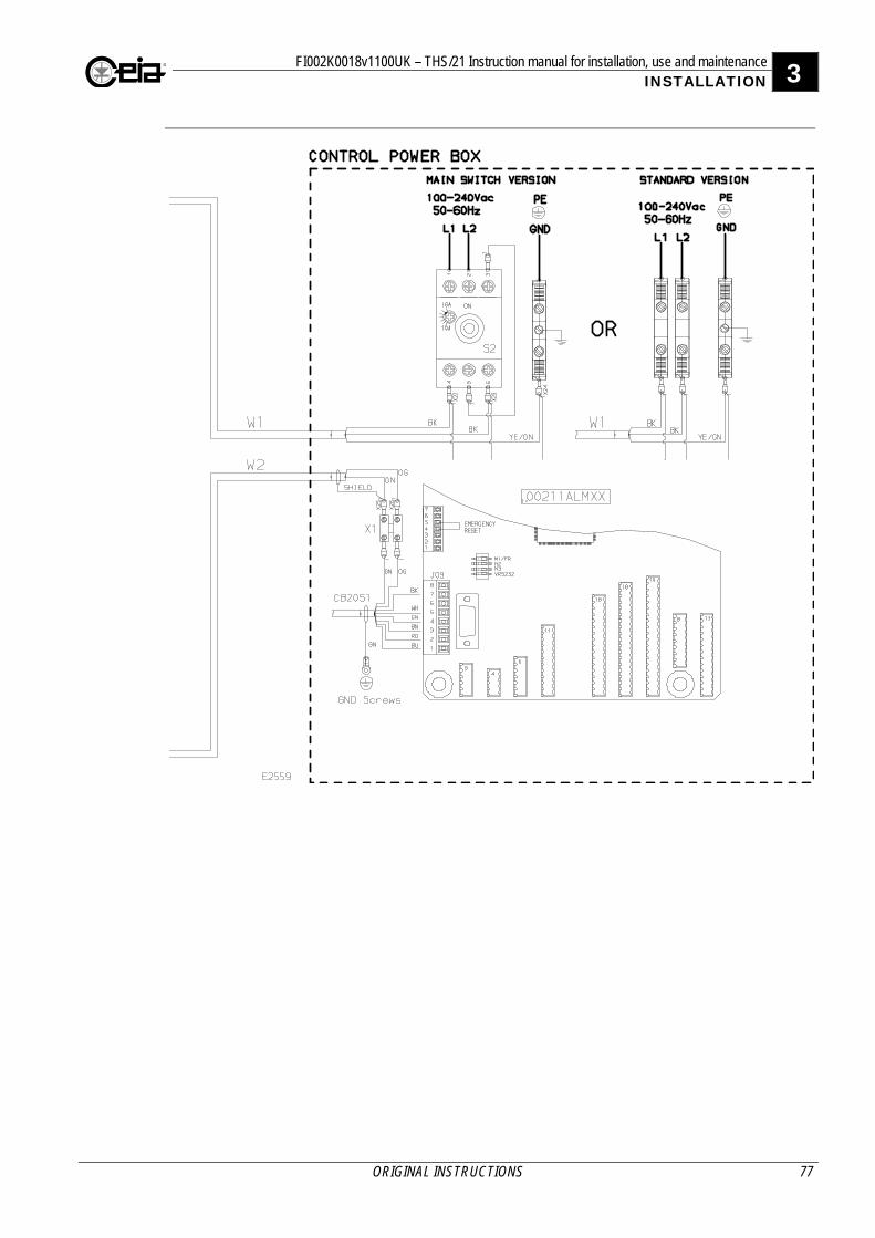
FI002K0018v1100UK – THS/21 Instruction manual for installation, use and maintenance 3 INSTALLATION
ORIGINAL INSTRUCTIONS 77
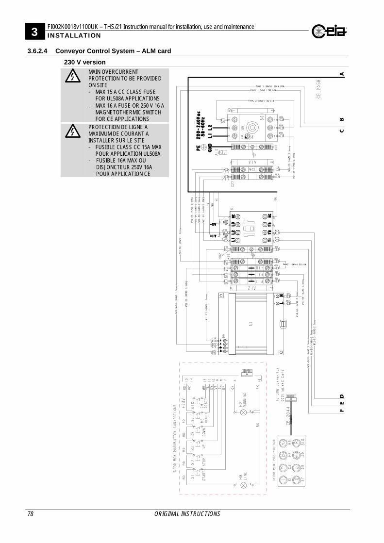
3 FI002K0018v1100UK – THS/21 Instruction manual for installation, use and maintenance INSTALLATION
78 ORIGINAL INSTRUCTIONS
3.6.2.4 Conveyor Control System – ALM card
230 V version
MAIN OVERCURRENT PROTECTION TO BE PROVIDED ON SITE - MAX 15 A CC CLASS FUSE
FOR UL508A APPLICATIONS - MAX 16 A FUSE OR 250 V 16 A
MAGNETOTHERMIC SWITCH FOR CE APPLICATIONS
PROTECTION DE LIGNE A MAXIMUM DE COURANT A INSTALLER SUR LE SITE - FUSIBLE CLASS CC 15A MAX
POUR APPLICATION UL508A - FUSIBLE 16A MAX OU
DISJONCTEUR 250V 16A POUR APPLICATION CE
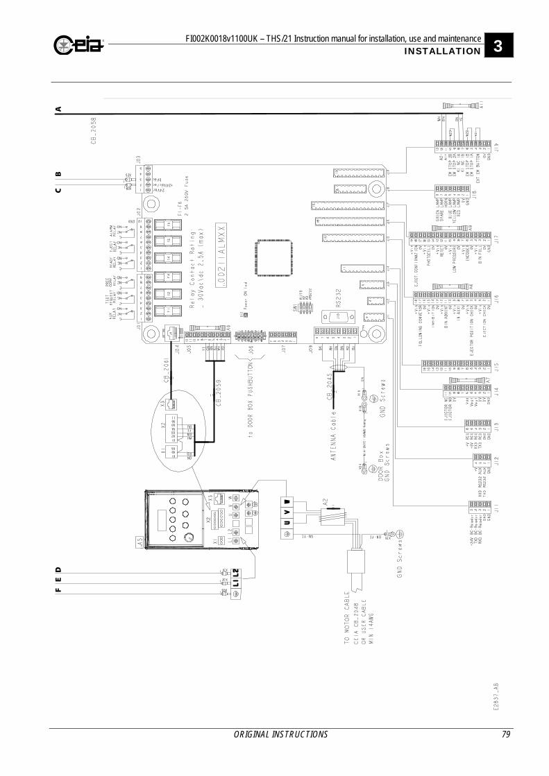
FI002K0018v1100UK – THS/21 Instruction manual for installation, use and maintenance 3 INSTALLATION
ORIGINAL INSTRUCTIONS 79
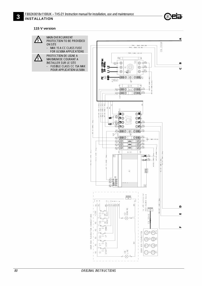
3 FI002K0018v1100UK – THS/21 Instruction manual for installation, use and maintenance INSTALLATION
80 ORIGINAL INSTRUCTIONS
115 V version
MAIN OVERCURRENT PROTECTION TO BE PROVIDED ON SITE - MAX 15 A CC CLASS FUSE
FOR UL508A APPLICATIONS
PROTECTION DE LIGNE A MAXIMUM DE COURANT A INSTALLER SUR LE SITE - FUSIBLE CLASS CC 15A MAX
POUR APPLICATION UL508A
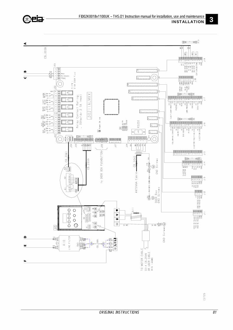
FI002K0018v1100UK – THS/21 Instruction manual for installation, use and maintenance 3 INSTALLATION
ORIGINAL INSTRUCTIONS 81
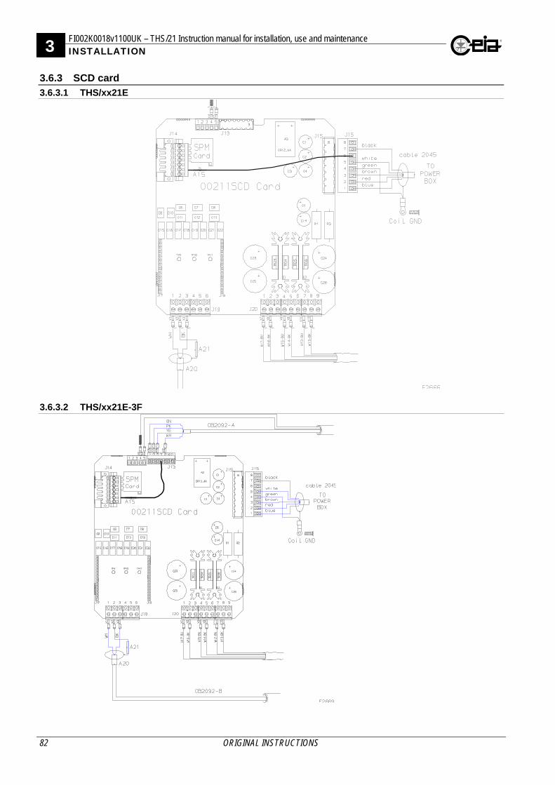
3 FI002K0018v1100UK – THS/21 Instruction manual for installation, use and maintenance INSTALLATION
82 ORIGINAL INSTRUCTIONS
3.6.3 SCD card
3.6.3.1 THS/xx21E
3.6.3.2 THS/xx21E-3F
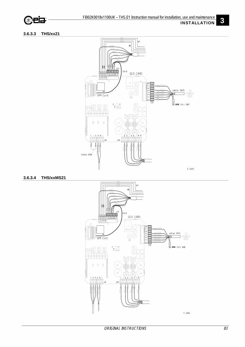
FI002K0018v1100UK – THS/21 Instruction manual for installation, use and maintenance 3 INSTALLATION
ORIGINAL INSTRUCTIONS 83
3.6.3.3 THS/xx21
3.6.3.4 THS/xxMS21
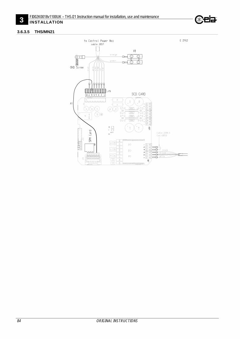
3 FI002K0018v1100UK – THS/21 Instruction manual for installation, use and maintenance INSTALLATION
84 ORIGINAL INSTRUCTIONS
3.6.3.5 THS/MN21
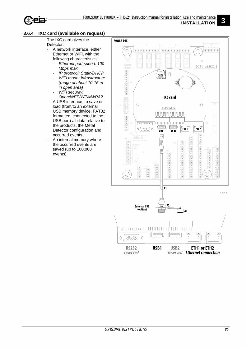
FI002K0018v1100UK – THS/21 Instruction manual for installation, use and maintenance 3 INSTALLATION
ORIGINAL INSTRUCTIONS 85
3.6.4 IXC card (available on request) The IXC card gives the Detector: - A network interface, either
Ethernet or WiFi, with the following characteristics: - Ethernet port speed: 100
Mbps max - IP protocol: Static/DHCP - WiFi mode: Infrastructure
(range of about 10-15 m in open area)
- WiFi security: Open/WEP/WPA/WPA2
- A USB interface, to save or load (from/to an external USB memory device, FAT32 formatted, connected to the USB port) all data relative to the products, the Metal Detector configuration and occurred events.
- An internal memory where the occurred events are saved (up to 100,000 events).
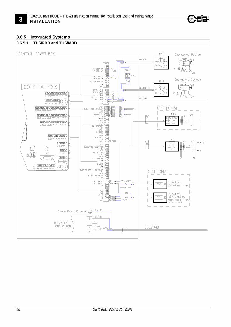
3 FI002K0018v1100UK – THS/21 Instruction manual for installation, use and maintenance INSTALLATION
86 ORIGINAL INSTRUCTIONS
3.6.5 Integrated Systems
3.6.5.1 THS/FBB and THS/MBB
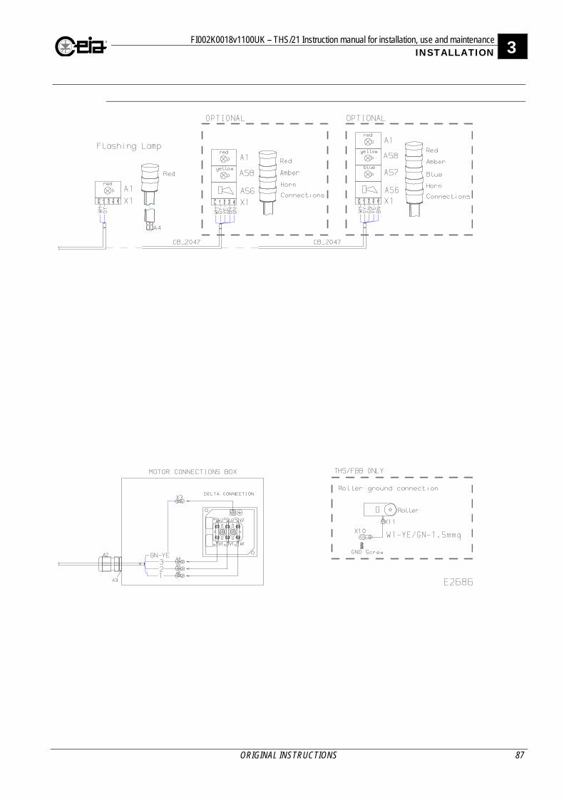
FI002K0018v1100UK – THS/21 Instruction manual for installation, use and maintenance 3 INSTALLATION
ORIGINAL INSTRUCTIONS 87

3 FI002K0018v1100UK – THS/21 Instruction manual for installation, use and maintenance INSTALLATION
88 ORIGINAL INSTRUCTIONS
3.6.5.2 THS/FBB and THS/MBB with Bin full and Low pressure sensors
FI002K0018v1100UK – THS/21 Instruction manual for installation, use and maintenance 3 INSTALLATION
ORIGINAL INSTRUCTIONS 89
3 FI002K0018v1100UK – THS/21 Instruction manual for installation, use and maintenance INSTALLATION
90 ORIGINAL INSTRUCTIONS
3.6.5.3 THS/FB, THS/MBR, THS/M65 and THS/M69K
FI002K0018v1100UK – THS/21 Instruction manual for installation, use and maintenance 3 INSTALLATION
ORIGINAL INSTRUCTIONS 91
3 FI002K0018v1100UK – THS/21 Instruction manual for installation, use and maintenance INSTALLATION
92 ORIGINAL INSTRUCTIONS
3.7 Connections to other devices
3.7.1 00211ALM card
Connector Pin Label IN/OUT Type Range/Max. value
Function
J011
1 C
Output
Common
30 V AC/DC 2.5A
Auxiliary relay (not used) 2 NC N.C. contact
3 NO N.O. contact
4 C
Output
common
Test request 5 NC N.C. contact
6 NO N.O. contact
7 C
Output
common
Upstream conveyor relay 8 NC N.C. contact
9 NO N.O. contact
J02
1 C
Output
common
30 V AC/DC 2.5A
Ready relay 2 NC N.C. contact
3 NO N.O. contact
4 C
Output
common
Ejection relay 5 NC N.C. contact
6 NO N.O. contact
7 C
Output
common
Alarm relay 8 NC N.C. contact
9 NO N.O. contact
10 GND - ground -
J03
1 24 Vac
Input
24 Vac
24 V power supply input from AC/DC converter 2 +24 Vdc/ac +24 Vdc/ac
3 0 Vdc 0 Vdc
4 - - - - Reserved
5 - - - -
J04 Only used with the inverter module on Conveyor Control System
J05 Reserved
J06 Reserved
J071
1 - - - -
Reserved 2 - - - -
3 - - - -
4 ] Emergency reset input Keep jumpered on Control Power Box 5
6 - - - - Reserved
7 - - - -
J08 Reserved 1 Connector not present on Control Power Box – basic version
FI002K0018v1100UK – THS/21 Instruction manual for installation, use and maintenance 3 INSTALLATION
ORIGINAL INSTRUCTIONS 93
Connector Pin Label IN/OUT Type Range/Max. value Function
J09
1 BU
Res
erve
d
-16V
Reserved for the antenna connection
2 RD +16V
3 BN +5.6V
4 GN GND
5 WH Data
6 -
7 BK Data
8 -
J10
1
-
+24V 100 mA max RS-232 serial connection The 24 V on pin 1 is present only if the minidip VRS232 of switcher SW1 is set to ON. By default it is set to OFF.
2 RXD
3 TXD
5 0 V
6 DTR
J111
1 GND
-
GND
Barcode reader connection If the Barcode reader connected needs a current higher than 150 mA, an external power supply must be used leaving pin 5 disconnected.
2 GND GND
3 RXD Data
4 TXD Data
5 +24V BC Reader +24V 150 mA max
J12
1 GND
-
GND
Auxiliary serial port communication 2 TXD Data
3 RXD Data
4 +V +24V 150 mA max
J13
1 GND
Res
erve
d
GND
Reserved for RCU connection
2 GND GND
3 TXD Data
4 RXD Data
5 +5V +5V
6 +V 24V
J14
1 GND GND
2 0V 0V
3 0V 0V
4 Vout 2 Output 24V
5 Vout 2 Output 24V
6 Vdd
Reserved 7 -
8 -
9 0V 0V
10 Ejector NO 2,3 Output 0 ÷ Vout Ejection system connection
11 Ejector NC 2,3 Output 0 ÷ Vout
J15 Reserved 1 Connector not present on Control Power Box – basic version 2 The output can provide an overall maximum current of 150 mA. In case of an emergency, the output is set to 0 V. 3 Ejector driving: Ejector NO: NO solenoid valve driving; Ejector NC: NC solenoid valve driving.
3 FI002K0018v1100UK – THS/21 Instruction manual for installation, use and maintenance INSTALLATION
94 ORIGINAL INSTRUCTIONS
Connector Pin Label IN/OUT Type Range/Max. value
Function
J161
1 0V 0V
Connection of ejection system check sensor 2 Ej. check Input
3 +Vin 24V 2
4 0V 0V
Connection of ejector position check sensor 5 EJ.POS. CHK Input
6 +Vin 24V 2
7 0V 0V Connection of a button (NA) to activate Test request
8 IN AUX1 Input
9 +Vin 24V 2
10 0V 0V
Connection of bin absent sensor 11 Bin absent Input
12 +Vin 24V 2
13 0V 0V
Connection of Metal Detector inhibition signal 14 Inhibition Input
15 +Vin 24V 2
16 0V 0V
Connection for Following Conveyor enabling signal 17 Foll.Conv. Input
18 +Vin 24V 2
J17
1 GND
2 0V 0V
Connection of bin full level sensor 3 BIN FULL Input
4 +Vin 24V 2
5 0V 0V Connection of an encoder Maximum pulse frequency: 3 kHz Type: push-pull 24 V
6 Encoder Input
7 +Vin 24V 2
8 0V 0V
Connection of a low pressure sensor 9 Low pressure Input
10 +Vin 24V 2
11 0V 0V
Connection of a reset pushbutton (NO) 12 Reset Input
13 +Vin 24V 2
14 0V 0V
Connection of the synchronization photocell 15 Photocell Input
16 +Vin 24V 2
17 0V 0V
Connection of ejection confirmation sensor 18 EJ.CONFIRM Input
19 +Vin 24V 2 1 Connector not present on Control Power Box – basic version 2 The +Vin power supply can provide an overall maximum current of 150mA.
FI002K0018v1100UK – THS/21 Instruction manual for installation, use and maintenance 3 INSTALLATION
ORIGINAL INSTRUCTIONS 95
Connector Pin Label IN/OUT Type Range/Max. value
Function
J181
1 GND GND
Connection of the beacon and horn
2 0V 0 V
3 RED LAMP Output Fault signal 0/24V
4 YELLOW L. Output Alarm signal 0/24V
5 BLUE LAMP Output Test req. signal
0/24V
6 HORN Output Sound signal 0/24V
7 SPARE LAMP Output Reset backlight
0/24V Backlighting of external button connected to the RESET input, activated by the Reset request
8 WHITE L. Output Main signal 24V
J191
1 GND GND
2 0V 0 V
3 EXT EM BUTTON EXT EM BUTTON
External emergency button (NC single contact) If not used, keep jumpered 4 EXT EM BUTTON
5 EM STOP 1A EM STOP 1
External emergency button connections (NC double contact) 1 of 2. If not used, keep jumpered 6 EM STOP 1B
7 K1 NC -
Reserved for connection to relay K1. With Control Power Box, keep jumpered. 8
9 EM STOP 2A EM STOP 2
External emergency button connections (NC double contact) 2 of 2. If not used, keep jumpered 10 EM STOP 2B
11 -
Reserved 12 -
13 - 1 Connector not present on Control Power Box – basic version
3.7.2 00211AL_ card
Connector Pin Label IN/OUT Type Range/Max. value
Function
J1
1 C
Output
common
30 V AC/DC 2.5A
Ready relay 2 NC N.C. contact
3 NO N.O. contact
4 C
Output
common
Ejector relay 5 NC N.C. contact
6 NO N.O. contact
J2
1 GND
Res
erve
d
GND
Reserved for RCU connection
2 GND GND
3 TXD Data
4 RXD Data
5 +5V +5 V
6 +V +24 V
J3
1
-
+24 V 100 mA max RS-232 serial connection The 24 V on pin 1 is present only if the minidip VRS232 of switcher SW1 is set to ON. By default it is set to OFF.
2 RXD
3 TXD
5 0 V
6 DTR
3 FI002K0018v1100UK – THS/21 Instruction manual for installation, use and maintenance INSTALLATION
96 ORIGINAL INSTRUCTIONS
Connector Pin Label IN/OUT Type Range/Max. value
Function
J4
1 GND
-
GND
Auxiliary serial port communication 2 TXD Data
3 RXD Data
4 +V +24 V 150 mA max
J5
1 GND
2 +Vin
Input
24V
Connection of ejection confirmation sensor 3 EJ.CONFIRM
4 0V 0V
5 +Vin 1
Input
24V
Connection of the synchronization photocell 6 Photocell
7 0V 0V
8 +Vin 1
Input
24V
Connection of a reset push-button 9 Reset
10 0V 0V
11 +Vin 1
Input
24V
Connection of an encoder 12 ENCODER
13 0V 0V
J6 Reserved
J7 Reserved
J8
1 24 Vac
Input
24 Vac 20 – 30 V
24 V power supply input from AC/DC converter 2 +24 Vdc/ac +24 Vdc/ac
3 0 Vdc 0 Vdc
4 - - - - Reserved
5 - - - -
J9
1 BU
Res
erve
d
-16V
Reserved for the antenna
2 RD +16V
3 BN +5,6V
4 GN GND
5 WH Data
6 -
7 BK Data
8 - 1 The +Vin power supply can provide an overall maximum current of 150mA.
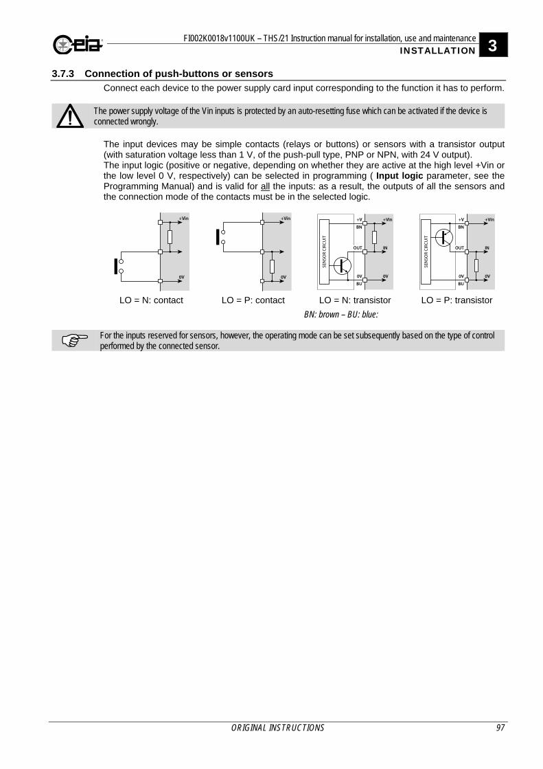
FI002K0018v1100UK – THS/21 Instruction manual for installation, use and maintenance 3 INSTALLATION
ORIGINAL INSTRUCTIONS 97
3.7.3 Connection of push-buttons or sensors Connect each device to the power supply card input corresponding to the function it has to perform.
The power supply voltage of the Vin inputs is protected by an auto-resetting fuse which can be activated if the device is connected wrongly.
The input devices may be simple contacts (relays or buttons) or sensors with a transistor output (with saturation voltage less than 1 V, of the push-pull type, PNP or NPN, with 24 V output). The input logic (positive or negative, depending on whether they are active at the high level +Vin or the low level 0 V, respectively) can be selected in programming ( Input logic parameter, see the Programming Manual) and is valid for all the inputs: as a result, the outputs of all the sensors and the connection mode of the contacts must be in the selected logic.
LO = N: contact LO = P: contact LO = N: transistor LO = P: transistor
BN: brown – BU: blue:
For the inputs reserved for sensors, however, the operating mode can be set subsequently based on the type of control performed by the connected sensor.
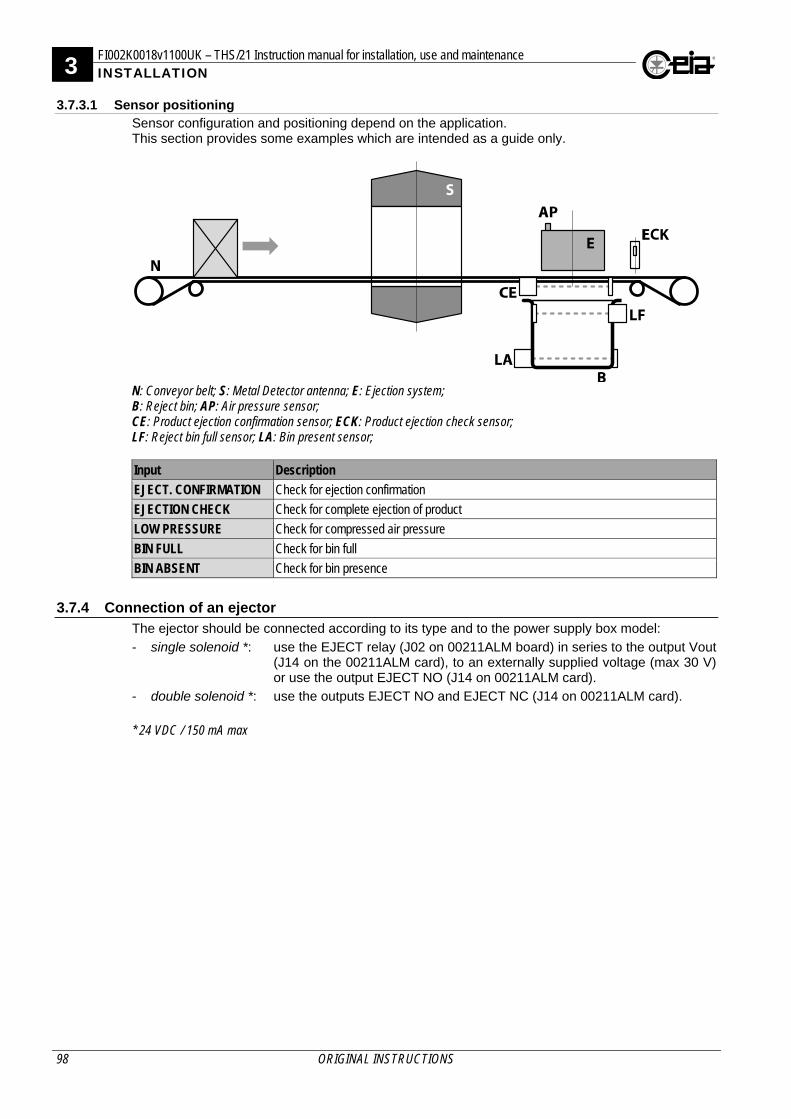
3 FI002K0018v1100UK – THS/21 Instruction manual for installation, use and maintenance INSTALLATION
98 ORIGINAL INSTRUCTIONS
3.7.3.1 Sensor positioning Sensor configuration and positioning depend on the application. This section provides some examples which are intended as a guide only.
N: Conveyor belt; S: Metal Detector antenna; E: Ejection system; B: Reject bin; AP: Air pressure sensor; CE: Product ejection confirmation sensor; ECK: Product ejection check sensor; LF: Reject bin full sensor; LA: Bin present sensor; Input Description
EJECT. CONFIRMATION Check for ejection confirmation
EJECTION CHECK Check for complete ejection of product
LOW PRESSURE Check for compressed air pressure
BIN FULL Check for bin full
BIN ABSENT Check for bin presence
3.7.4 Connection of an ejector The ejector should be connected according to its type and to the power supply box model:
- single solenoid *: use the EJECT relay (J02 on 00211ALM board) in series to the output Vout (J14 on the 00211ALM card), to an externally supplied voltage (max 30 V) or use the output EJECT NO (J14 on 00211ALM card).
- double solenoid *: use the outputs EJECT NO and EJECT NC (J14 on 00211ALM card).
* 24 VDC / 150 mA max
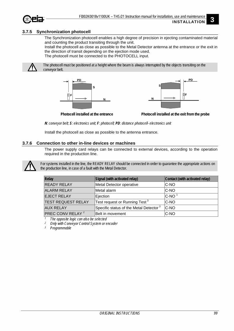
FI002K0018v1100UK – THS/21 Instruction manual for installation, use and maintenance 3 INSTALLATION
ORIGINAL INSTRUCTIONS 99
3.7.5 Synchronization photocell The Synchronization photocell enables a high degree of precision in ejecting contaminated material and counting the product transiting through the unit. Install the photocell as close as possible to the Metal Detector antenna at the entrance or the exit in the direction of transit depending on the ejection mode used. The photocell must be connected to the PHOTOCELL input.
The photocell must be positioned at a height where the beam is always interrupted by the objects transiting on the conveyor belt.
F
S
N
PD
F
S
N
PD
Photocell installed at the entrance
Photocell installed at the exit from the probe
N: conveyor belt; S: electronics unit; F: photocell; PD: distance photocell- electronics unit Install the photocell as close as possible to the antenna entrance.
3.7.6 Connection to other in-line devices or machines The power supply card relays can be connected to external devices, according to the operation required in the production line.
For systems installed in the line, the READY RELAY should be connected in order to guarantee the appropriate actions on the production line, in case of a fault with the Metal Detector.
Relay Signal (with activated relay) Contact (with activated relay)
READY RELAY Metal Detector operative C-NO
ALARM RELAY Metal alarm C-NO
EJECT RELAY Ejection C-NO 1
TEST REQUEST RELAY Test request or Running Test 3 C-NO
AUX RELAY Specific status of the Metal Detector 3 C-NO
PREC CONV RELAY 2 Belt in movement C-NO 1 The opposite logic can also be selected 2 Only with Conveyor Control System or encoder 3 Programmable
3 FI002K0018v1100UK – THS/21 Instruction manual for installation, use and maintenance INSTALLATION
100 ORIGINAL INSTRUCTIONS
3.8 Configuration
CEIA integrated systems are already programmed (see Factory Acceptance Test enclosed with the manual). On non-integrated systems, the programming parameters must be set to match the type of installation. For instructions on entering the programming phase and modifying the parameter values, refer to the Programming Manual.
In the following section, access to Programming as Administrator is required. User: ADMINI – Password: 000000
To keep things simple, the parameters will be referred to using the short name valid for remote Programming.
3.8.1 System start-up If the equipment is being switched on for the first time, some checks must be carried out and the value of some operating parameters must be set. These operations, which are listed on the first page of the Installation section, are described below in this section.
When it is first powered up, the Metal Detector configuration includes 6 factory-set passwords (shown on the test card at the end of the manual). It is extremely important that the person in charge of the detector modifies the passwords in order to avoid unauthorized access to programming.
3.8.2 Preliminary settings
- Enter the Configuration menu and set the correct values for the following parameters: Language, Date and Time.
- In the case of adjacent Metal Detectors, if necessary, set a transmission channel different from the other Metal Detector, using the TX channel parameter.
3.8.3 Checking the input and output connections
If input or output devices do not need to be connected for the installation of the Metal Detector, go to the next paragraph.
1. Enter the Configuration-adv menu and select, according to the devices connected, the input logic, setting the Input logic parameter to P or N.
2. Enter the Configuration-adv > I/O Status > Inputs menu and simulate the operating
condition for activation of each connected input line, verifying that the corresponding status changes correctly from L to H.
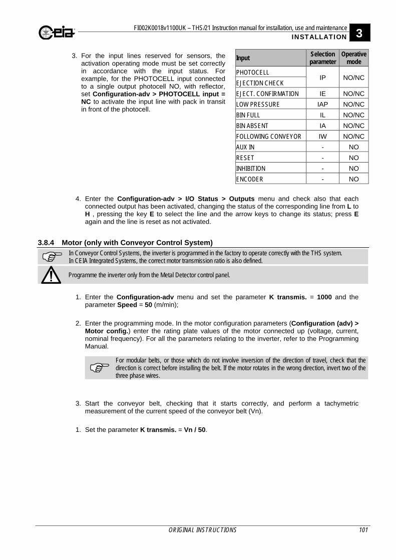
FI002K0018v1100UK – THS/21 Instruction manual for installation, use and maintenance 3 INSTALLATION
ORIGINAL INSTRUCTIONS 101
3. For the input lines reserved for sensors, the activation operating mode must be set correctly in accordance with the input status. For example, for the PHOTOCELL input connected to a single output photocell NO, with reflector, set Configuration-adv > PHOTOCELL input = NC to activate the input line with pack in transit in front of the photocell.
Input Selection parameter
Operative mode
PHOTOCELL IP NO/NC
EJECTION CHECK
EJECT. CONFIRMATION IE NO/NC
LOW PRESSURE IAP NO/NC
BIN FULL IL NO/NC
BIN ABSENT IA NO/NC
FOLLOWING CONVEYOR IW NO/NC
AUX IN - NO
RESET - NO
INHIBITION - NO
ENCODER - NO
4. Enter the Configuration-adv > I/O Status > Outputs menu and check also that each connected output has been activated, changing the status of the corresponding line from L to H , pressing the key E to select the line and the arrow keys to change its status; press E again and the line is reset as not activated.
3.8.4 Motor (only with Conveyor Control System)
In Conveyor Control Systems, the inverter is programmed in the factory to operate correctly with the THS system. In CEIA Integrated Systems, the correct motor transmission ratio is also defined.
Programme the inverter only from the Metal Detector control panel.
1. Enter the Configuration-adv menu and set the parameter K transmis. = 1000 and the
parameter Speed = 50 (m/min);
2. Enter the programming mode. In the motor configuration parameters (Configuration (adv) >
Motor config.) enter the rating plate values of the motor connected up (voltage, current, nominal frequency). For all the parameters relating to the inverter, refer to the Programming Manual.
For modular belts, or those which do not involve inversion of the direction of travel, check that the direction is correct before installing the belt. If the motor rotates in the wrong direction, invert two of the three phase wires.
3. Start the conveyor belt, checking that it starts correctly, and perform a tachymetric measurement of the current speed of the conveyor belt (Vn).
1. Set the parameter K transmis. = Vn / 50.
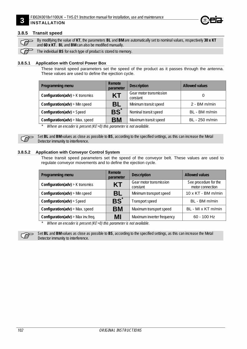
3 FI002K0018v1100UK – THS/21 Instruction manual for installation, use and maintenance INSTALLATION
102 ORIGINAL INSTRUCTIONS
3.8.5 Transit speed
By modifying the value of KT, the parameters BL and BM are automatically set to nominal values, respectively 30 x KT and 60 x KT. BL and BM can also be modified manually.
The individual BS for each type of product is stored to memory.
3.8.5.1 Application with Control Power Box
These transit speed parameters set the speed of the product as it passes through the antenna. These values are used to define the ejection cycle.
Programming menu Remote parameter
Description Allowed values
Configuration(adv) > K transmiss KT Gear motor transmission constant
0
Configuration(adv) > Min speed BL Minimum transit speed 2 - BM m/min
Configuration(adv) > Speed BS* Nominal transit speed BL - BM m/min
Configuration(adv) > Max. speed BM Maximum transit speed BL - 250 m/min
* Where an encoder is present (KE>0) this parameter is not available.
Set BL and BM values as close as possible to BS, according to the specified settings, as this can increase the Metal Detector immunity to interference.
3.8.5.2 Application with Conveyor Control System
These transit speed parameters set the speed of the conveyor belt. These values are used to regulate conveyor movements and to define the ejection cycle.
Programming menu Remote parameter Description Allowed values
Configuration(adv) > K transmiss KT Gear motor transmission constant
See procedure for the motor connection
Configuration(adv) > Min speed BL Minimum transport speed 10 x KT - BM m/min
Configuration(adv) > Speed BS* Transport speed BL - BM m/min
Configuration(adv) > Max. speed BM Maximum transport speed BL - MI x KT m/min
Configuration(adv) > Max inv.freq. MI Maximum inverter frequency 60 - 100 Hz
* Where an encoder is present (KE>0) this parameter is not available.
Set BL and BM values as close as possible to BS, according to the specified settings, as this can increase the Metal Detector immunity to interference.
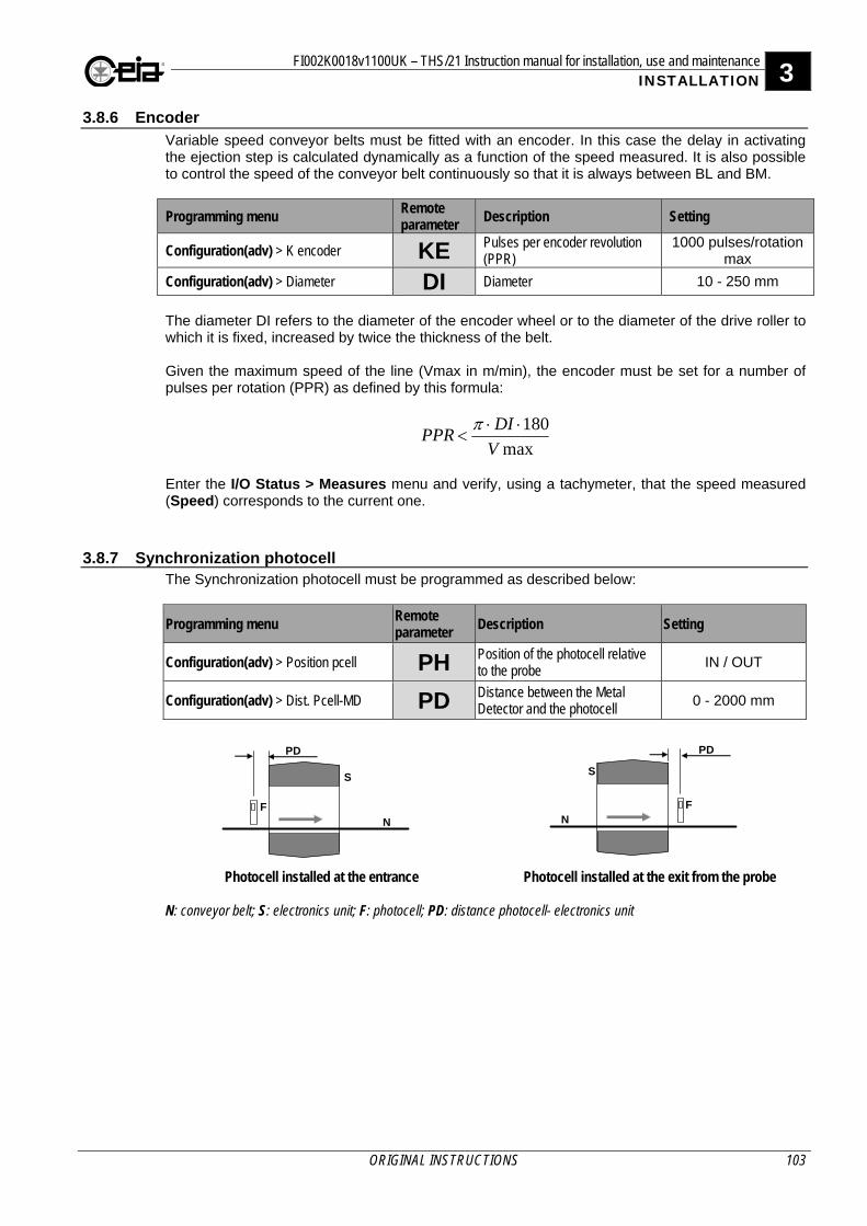
FI002K0018v1100UK – THS/21 Instruction manual for installation, use and maintenance 3 INSTALLATION
ORIGINAL INSTRUCTIONS 103
3.8.6 Encoder Variable speed conveyor belts must be fitted with an encoder. In this case the delay in activating the ejection step is calculated dynamically as a function of the speed measured. It is also possible to control the speed of the conveyor belt continuously so that it is always between BL and BM.
Programming menu Remote parameter Description Setting
Configuration(adv) > K encoder KE Pulses per encoder revolution (PPR)
1000 pulses/rotation max
Configuration(adv) > Diameter DI Diameter 10 - 250 mm
The diameter DI refers to the diameter of the encoder wheel or to the diameter of the drive roller to which it is fixed, increased by twice the thickness of the belt. Given the maximum speed of the line (Vmax in m/min), the encoder must be set for a number of pulses per rotation (PPR) as defined by this formula:
max
180
V
DIPPR
Enter the I/O Status > Measures menu and verify, using a tachymeter, that the speed measured (Speed) corresponds to the current one.
3.8.7 Synchronization photocell The Synchronization photocell must be programmed as described below:
Programming menu Remote parameter Description Setting
Configuration(adv) > Position pcell PH Position of the photocell relative to the probe
IN / OUT
Configuration(adv) > Dist. Pcell-MD PD Distance between the Metal Detector and the photocell
0 - 2000 mm
F
S
N
PD
F
S
N
PD
Photocell installed at the entrance
Photocell installed at the exit from the probe
N: conveyor belt; S: electronics unit; F: photocell; PD: distance photocell- electronics unit
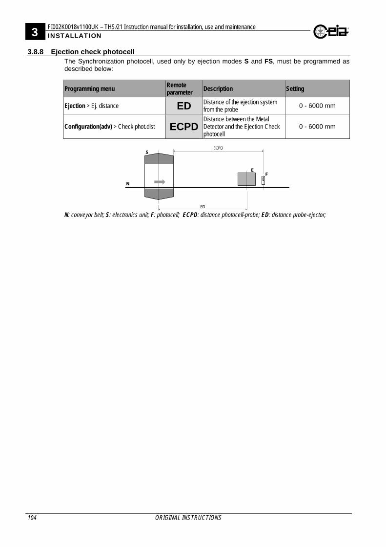
3 FI002K0018v1100UK – THS/21 Instruction manual for installation, use and maintenance INSTALLATION
104 ORIGINAL INSTRUCTIONS
3.8.8 Ejection check photocell The Synchronization photocell, used only by ejection modes S and FS, must be programmed as described below:
Programming menu Remote parameter
Description Setting
Ejection > Ej. distance ED Distance of the ejection system from the probe
0 - 6000 mm
Configuration(adv) > Check phot.dist ECPDDistance between the Metal Detector and the Ejection Check photocell
0 - 6000 mm
N: conveyor belt; S: electronics unit; F: photocell; ECPD: distance photocell-probe; ED: distance probe-ejector;
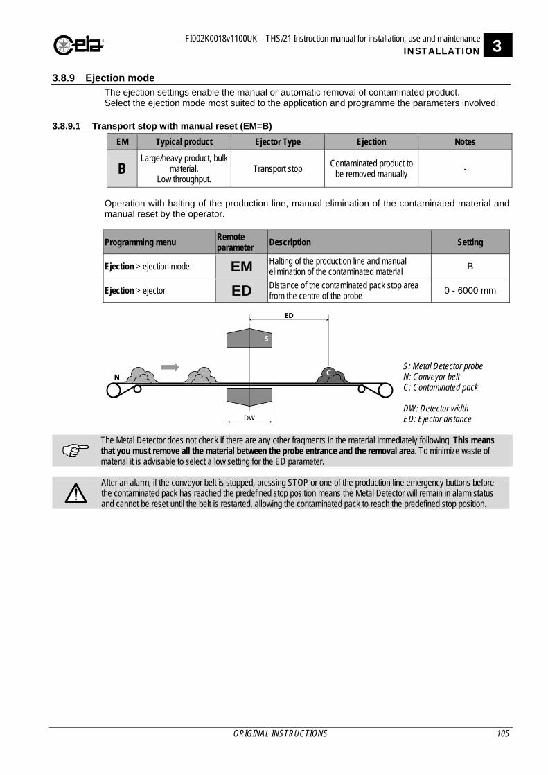
FI002K0018v1100UK – THS/21 Instruction manual for installation, use and maintenance 3 INSTALLATION
ORIGINAL INSTRUCTIONS 105
3.8.9 Ejection mode The ejection settings enable the manual or automatic removal of contaminated product. Select the ejection mode most suited to the application and programme the parameters involved:
3.8.9.1 Transport stop with manual reset (EM=B)
EM Typical product Ejector Type Ejection Notes
B Large/heavy product, bulk
material. Low throughput.
Transport stop Contaminated product to
be removed manually -
Operation with halting of the production line, manual elimination of the contaminated material and manual reset by the operator.
Programming menu Remote parameter Description Setting
Ejection > ejection mode EM Halting of the production line and manual elimination of the contaminated material
B
Ejection > ejector ED Distance of the contaminated pack stop area from the centre of the probe
0 - 6000 mm
S: Metal Detector probe N: Conveyor belt C: Contaminated pack DW: Detector width ED: Ejector distance
The Metal Detector does not check if there are any other fragments in the material immediately following. This means that you must remove all the material between the probe entrance and the removal area. To minimize waste of material it is advisable to select a low setting for the ED parameter.
After an alarm, if the conveyor belt is stopped, pressing STOP or one of the production line emergency buttons before the contaminated pack has reached the predefined stop position means the Metal Detector will remain in alarm status and cannot be reset until the belt is restarted, allowing the contaminated pack to reach the predefined stop position.
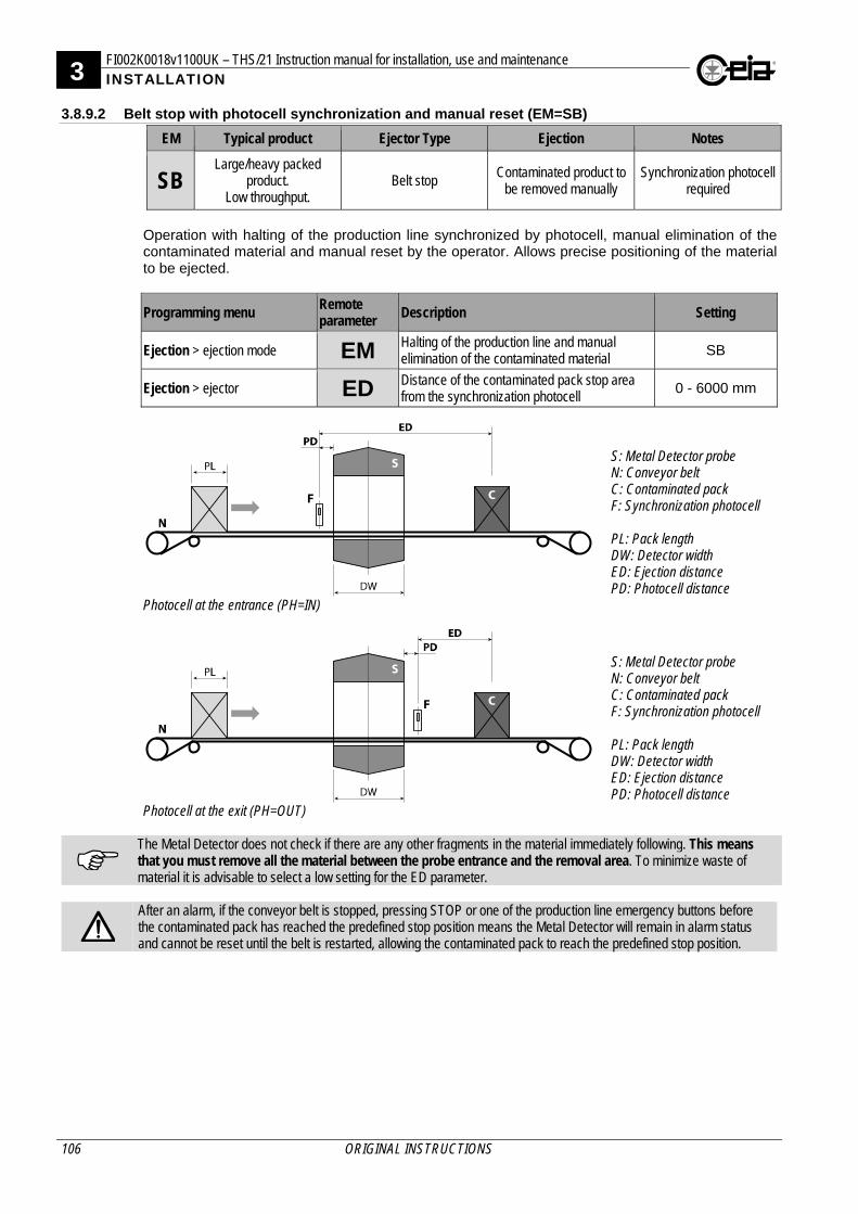
3 FI002K0018v1100UK – THS/21 Instruction manual for installation, use and maintenance INSTALLATION
106 ORIGINAL INSTRUCTIONS
3.8.9.2 Belt stop with photocell synchronization and manual reset (EM=SB)
EM Typical product Ejector Type Ejection Notes
SB Large/heavy packed
product. Low throughput.
Belt stop Contaminated product to
be removed manually Synchronization photocell
required
Operation with halting of the production line synchronized by photocell, manual elimination of the contaminated material and manual reset by the operator. Allows precise positioning of the material to be ejected.
Programming menu Remote parameter Description Setting
Ejection > ejection mode EM Halting of the production line and manual elimination of the contaminated material
SB
Ejection > ejector ED Distance of the contaminated pack stop area from the synchronization photocell
0 - 6000 mm
S: Metal Detector probe N: Conveyor belt C: Contaminated pack F: Synchronization photocell PL: Pack length DW: Detector width ED: Ejection distance PD: Photocell distance
Photocell at the entrance (PH=IN)
S: Metal Detector probe N: Conveyor belt C: Contaminated pack F: Synchronization photocell PL: Pack length DW: Detector width ED: Ejection distance PD: Photocell distance
Photocell at the exit (PH=OUT)
The Metal Detector does not check if there are any other fragments in the material immediately following. This means that you must remove all the material between the probe entrance and the removal area. To minimize waste of material it is advisable to select a low setting for the ED parameter.
After an alarm, if the conveyor belt is stopped, pressing STOP or one of the production line emergency buttons before the contaminated pack has reached the predefined stop position means the Metal Detector will remain in alarm status and cannot be reset until the belt is restarted, allowing the contaminated pack to reach the predefined stop position.
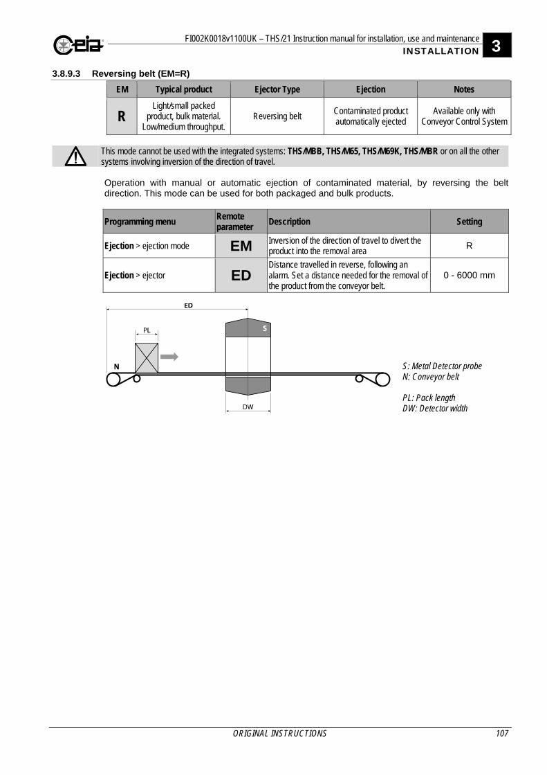
FI002K0018v1100UK – THS/21 Instruction manual for installation, use and maintenance 3 INSTALLATION
ORIGINAL INSTRUCTIONS 107
3.8.9.3 Reversing belt (EM=R)
EM Typical product Ejector Type Ejection Notes
R Light/small packed
product, bulk material. Low/medium throughput.
Reversing belt Contaminated product automatically ejected
Available only with Conveyor Control System
This mode cannot be used with the integrated systems: THS/MBB, THS/M65, THS/M69K, THS/MBR or on all the other systems involving inversion of the direction of travel. Operation with manual or automatic ejection of contaminated material, by reversing the belt direction. This mode can be used for both packaged and bulk products.
Programming menu Remote parameter
Description Setting
Ejection > ejection mode EM Inversion of the direction of travel to divert the product into the removal area
R
Ejection > ejector ED Distance travelled in reverse, following an alarm. Set a distance needed for the removal of the product from the conveyor belt.
0 - 6000 mm
S: Metal Detector probe N: Conveyor belt PL: Pack length DW: Detector width
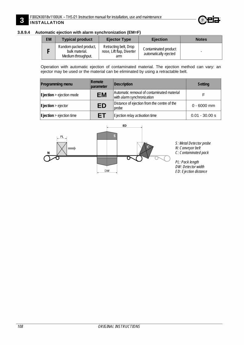
3 FI002K0018v1100UK – THS/21 Instruction manual for installation, use and maintenance INSTALLATION
108 ORIGINAL INSTRUCTIONS
3.8.9.4 Automatic ejection with alarm synchronization (EM=F)
EM Typical product Ejector Type Ejection Notes
F Random packed product,
bulk material. Medium throughput.
Retracting belt, Drop nose, Lift flap, Diverter
arm
Contaminated product automatically ejected
-
Operation with automatic ejection of contaminated material. The ejection method can vary: an ejector may be used or the material can be eliminated by using a retractable belt.
Programming menu Remote parameter
Description Setting
Ejection > ejection mode EM Automatic removal of contaminated material with alarm synchronization
F
Ejection > ejector ED Distance of ejection from the centre of the probe
0 - 6000 mm
Ejection > ejection time ET Ejection relay activation time 0.01 - 30.00 s
S: Metal Detector probe N: Conveyor belt C: Contaminated pack PL: Pack length DW: Detector width ED: Ejection distance
FI002K0018v1100UK – THS/21 Instruction manual for installation, use and maintenance 3 INSTALLATION
ORIGINAL INSTRUCTIONS 109
3.8.9.5 Automatic ejection with photocell synchronization (EM=S)
EM Typical product Ejector Type Ejection Notes
S Properly aligned and
spaced packed product. High throughput.
Air jet, Pusher Contaminated product automatically ejected
Synchronization photocell required
Operation with automatic ejection of contaminated material, synchronized by photocell. Very similar to the previous application, this mode can be used for packaged products.
Programming menu Remote parameter
Description Setting
Ejection > ejection mode EM Automatic removal of contaminated material with alarm synchronization
F
Ejection > ejector ED Distance of the ejector from the synchronization photocell
0 - 6000 mm
Ejection > ejection time ET Ejection relay activation time 0.01 - 30.00 s
Photocell at the entrance to the probe
S: Metal Detector probe N: Conveyor belt E: Ejector F1: Synchronization photocell F2: Ejection check sensor PL: Pack length DW: Detector width ED: Ejection distance PD: Photocell distance Dp: distance between packs
Photocell at the exit from the probe
S: Metal Detector probe N: Conveyor belt E: Ejector F1: Synchronization photocell F2: Ejection check sensor PL: Pack length DW: Detector width ED: Ejection distance PD: Photocell distance Dp: distance between packs
3 FI002K0018v1100UK – THS/21 Instruction manual for installation, use and maintenance INSTALLATION
110 ORIGINAL INSTRUCTIONS
3.8.9.6 Automatic ejection with photocell synchronization (EM=FS)
EM Typical product Ejector Type Ejection Notes
FS Single-line, light, poorly spaced packed product. Very high throughput.
Air jet Contaminated product automatically ejected
Synchronization photocell required
Operation with automatic ejection of contaminated material, synchronized by photocell. Very similar to the previous application, this mode can be used for packaged products, for applications at speeds greater than 60 m/min. The synchronizing photocell must be installed at the antenna exit only. In this case, the response times of the photocell, the Metal Detector and the ejector cannot be ignored. We would generally advise users to check operation of the ejector through trial and error, changing its position and adjusting parameter ED.
Programming menu Remote parameter
Description Setting
Ejection > ejection mode EM Automatic removal of contaminated material with synchronization on the removing area
FS
Ejection > ejector ED Distance of ejector from the centre of the probe 0 - 6000 mm
Ejection > pack length PLEN Nominal length of pack 20 - 250 mm
Ejection > eject.sync.start ES Synchronizing zone for the start of ejection 0 - 250 mm
Ejection > eject.sync.end EE Synchronizing zone for the end of ejection 0 - 250 mm
S: Metal Detector probe N: Conveyor belt A: Air jet ejector F1: Synchronization
photocell F2: Ejection check sensor PL: Pack length DW: Detector width ED: Ejection distance PD: Photocell distance ECPD: Photocell distance
E: Ejected pack; C: Contaminated and ejected pack; EE: Ejection end synchronization area; ES: Ejection start synchronization area R: Minimum removal area Re: Actual removal area = R+x+y
Following an alarm, the ejector will be activated for the time of the alarm and to eject all products in the PL+DW+PL area. A control can be introduced, from the photocell, of two areas alongside the removal area, in order to synchronize the start and end of the ejection with the packs in transit (ES and EE respectively). For more accurate adjustment of the ejection cycle, the early and delayed activation times can be adjusted based on the actual activation and deactivation times, respectively, using ERT and ERF.
FI002K0018v1100UK – THS/21 Instruction manual for installation, use and maintenance 3 INSTALLATION
ORIGINAL INSTRUCTIONS 111
3.8.10 Barcode reader Where present, the reader must be mounted upstream of the probe, in order to read a code stamped on the pack; it must be connected to connector J11 on the ALM card. If the code is recognized, the reader sends a command to the Metal Detector to select the relevant product type. The time required by the THS/21 to process the barcode is usually insignificant, but becomes significant if the detection mode, or band, is changed due to a modification in the type of product. When the Metal Detector receives the signal to change product type, an internal adjustment procedure is activated to adjust the length of the minimum distance between two packs with different codes, that is to say containing different products.
Programming menu Remote parameter
Description Setting
Configuration(adv) > Barcode enable BE Code provided by CEIA to enable the barcode reader.
6-digit alphanumeric string
Barcode reader * - Barcode reader settings -
* The menu is shown only when the barcode reader is enabled. The serial port of the barcode reader must be set to: 9600,N,8,1. The following code formats are supported: - XXXXXX<CR> - XXXXXX<CR><LF> - <STX>XXXXXX<ETX>
Where XXXXXX is a string of 48 characters (max.)
3.8.10.1 With change of Detection Mode or Band between two products For more information about the Detection Mode, see the DM Parameter section of the Programming Manual. For more information about the Band, see the BA Parameter section of the Programming Manual.
Distance between the packs
Distance between the barcode reader and the THS/21 probe
Dp L + 3000 mm Dsbr 3000 mm
S: probe/electronics unit of the Metal Detector; L: length of probe; N: conveyor belt; BR: Barcode reader;
Dsbr:Distance THS/21 probe-barcode reader; Dp: Distance between the packs of different products Installing the barcode reader closer than 3000 mm will result in product ejection during two detection mode cycles. After the cycle time, the system will be operated normally.
3.8.10.2 Without change of Detection Mode or Band between two products
L
S
Dp
BR
N
Dsbr
Distance between the packs
Distance between the barcode reader and the THS/21 probe
Dp L + 300 mm Dsbr 300 mm
S: probe/electronics unit of the Metal Detector; L: length of probe; N: conveyor belt; BR: Barcode reader;
Dsbr:Distance THS/21 probe-barcode reader; Dp: Distance between the packs of different products
These distances are indicative and also depend on the speed of transit of the products involved.
L
S
Dp
BR
N
Dsbr
3 FI002K0018v1100UK – THS/21 Instruction manual for installation, use and maintenance INSTALLATION
112 ORIGINAL INSTRUCTIONS
3.9 Timing
This section describes the timings for the signals activated after a stoppage. For systems fitted with a Conveyor Control System or Control Power Box with encoder, the timings are based on the actual speed of the conveying system. For systems with a Control Power Box without encoder, the timings are based on the speed set in the BS parameter and do not take into account any transit stoppages after an alarm or during ejection. In applications with intermittent product conveying, we recommend synchronizing with the conveyor signal (for details see paragraph 3.10).
3.9.1 Belt stop (EM=B)
S: Metal Detector probe N: Conveyor belt C: Contaminated pack PL: Pack length DW: Detector width ED: Ejector distance
Conveyor Control System Waveform Description
Metal alarm Metal alarm
Conveyor belt movement Conveyor belt movement
Alarm relay (ALARM) External alarm signalling
Ejection relay (EJECT) Not activated
Reset button Alarm reset
Start button Belt restart
Yellow lamp Alarm beacon operation
ED = Stop area distance; BS = Transit speed set on BS parameter or, in presence of an encoder (KE>0), measured
Control Power Box Waveform Description
Metal alarm Metal alarm
Alarm relay (ALARM) External alarm signalling
Ejection relay (EJECT) Product transportation stop
Reset button Alarm reset
Yellow lamp Alarm beacon operation
ED = Stop area distance; BS = Transit speed set on BS parameter or, in presence of an encoder (KE>0), measured
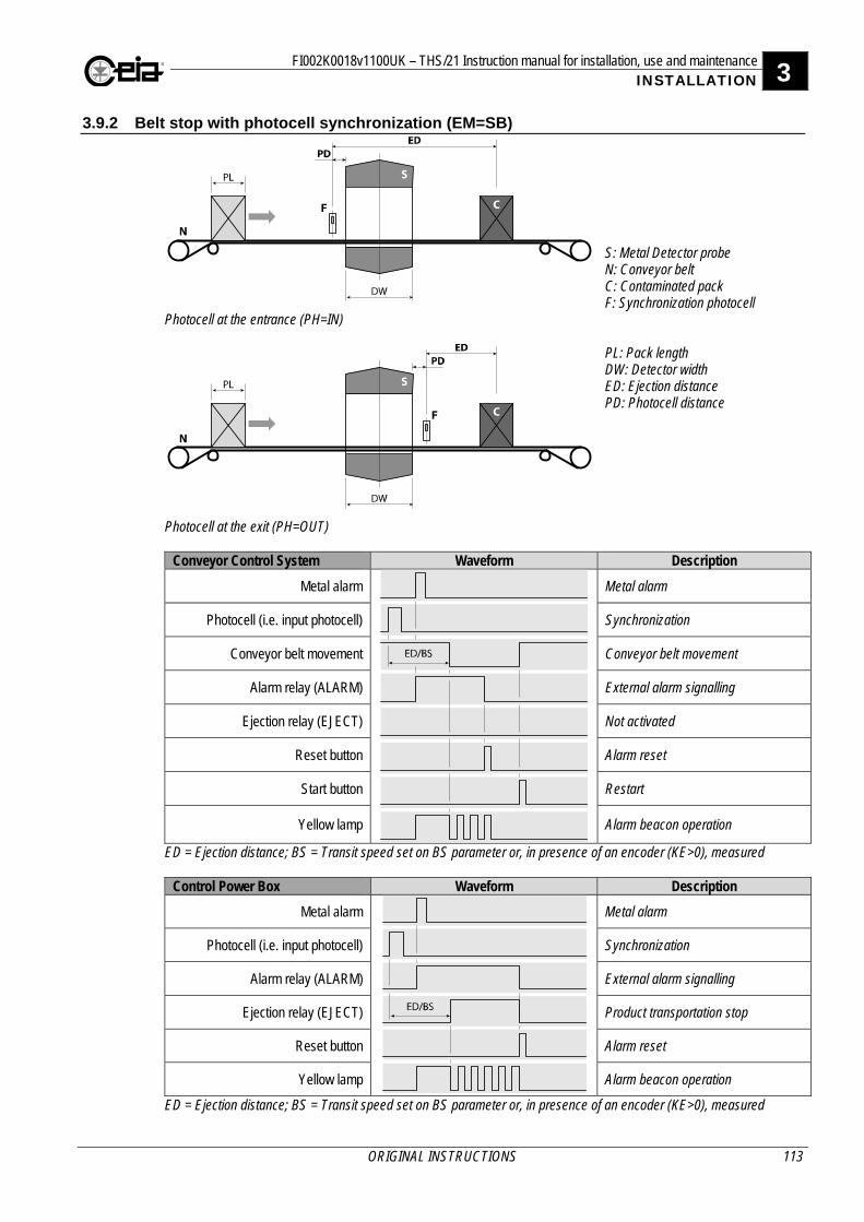
FI002K0018v1100UK – THS/21 Instruction manual for installation, use and maintenance 3 INSTALLATION
ORIGINAL INSTRUCTIONS 113
3.9.2 Belt stop with photocell synchronization (EM=SB)
S: Metal Detector probe N: Conveyor belt C: Contaminated pack F: Synchronization photocell
Photocell at the entrance (PH=IN)
PL: Pack length DW: Detector width ED: Ejection distance PD: Photocell distance
Photocell at the exit (PH=OUT)
Conveyor Control System Waveform Description
Metal alarm Metal alarm
Photocell (i.e. input photocell) Synchronization
Conveyor belt movement Conveyor belt movement
Alarm relay (ALARM) External alarm signalling
Ejection relay (EJECT) Not activated
Reset button Alarm reset
Start button Restart
Yellow lamp Alarm beacon operation
ED = Ejection distance; BS = Transit speed set on BS parameter or, in presence of an encoder (KE>0), measured
Control Power Box Waveform Description
Metal alarm Metal alarm
Photocell (i.e. input photocell) Synchronization
Alarm relay (ALARM) External alarm signalling
Ejection relay (EJECT) Product transportation stop
Reset button Alarm reset
Yellow lamp Alarm beacon operation
ED = Ejection distance; BS = Transit speed set on BS parameter or, in presence of an encoder (KE>0), measured
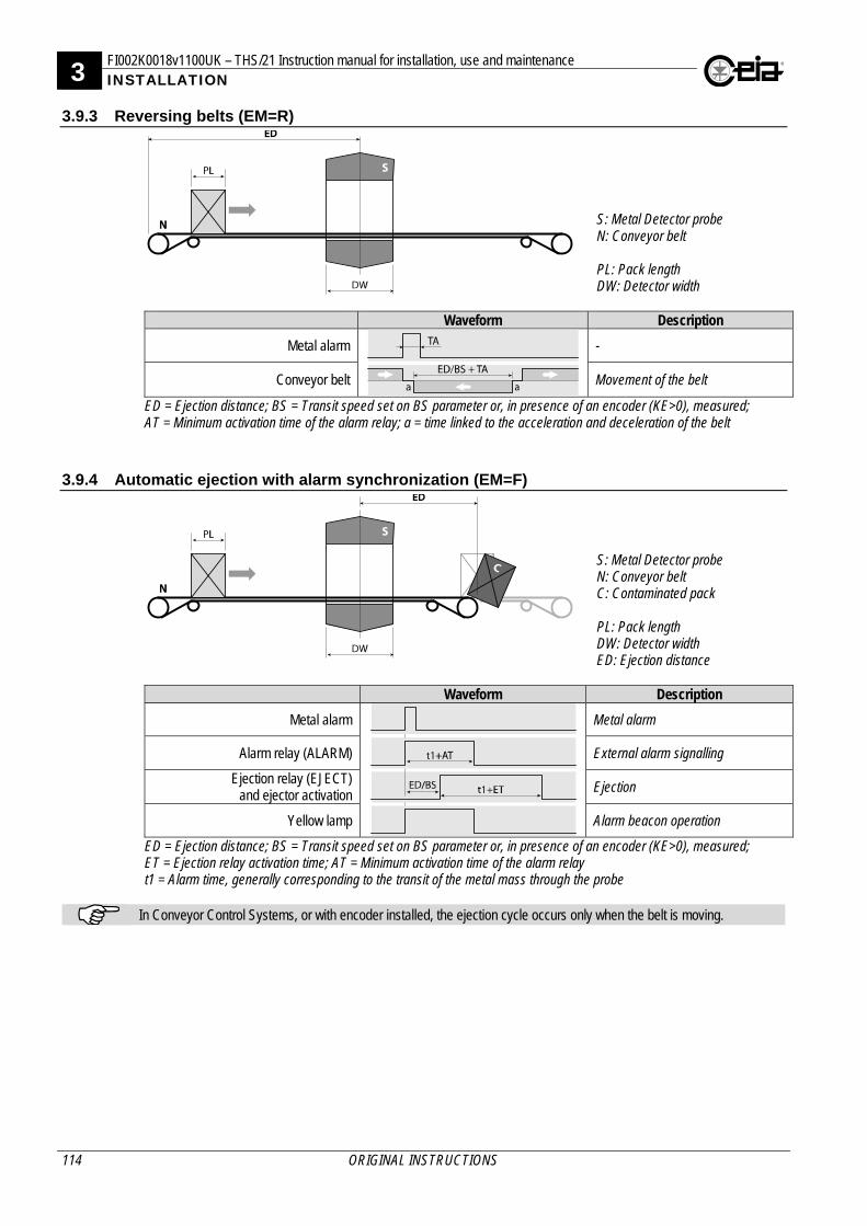
3 FI002K0018v1100UK – THS/21 Instruction manual for installation, use and maintenance INSTALLATION
114 ORIGINAL INSTRUCTIONS
3.9.3 Reversing belts (EM=R)
S: Metal Detector probe N: Conveyor belt PL: Pack length DW: Detector width
Waveform Description
Metal alarm -
Conveyor belt Movement of the belt
ED = Ejection distance; BS = Transit speed set on BS parameter or, in presence of an encoder (KE>0), measured; AT = Minimum activation time of the alarm relay; a = time linked to the acceleration and deceleration of the belt
3.9.4 Automatic ejection with alarm synchronization (EM=F)
S: Metal Detector probe N: Conveyor belt C: Contaminated pack PL: Pack length DW: Detector width ED: Ejection distance
Waveform Description
Metal alarm Metal alarm
Alarm relay (ALARM) External alarm signalling
Ejection relay (EJECT) and ejector activation Ejection
Yellow lamp Alarm beacon operation
ED = Ejection distance; BS = Transit speed set on BS parameter or, in presence of an encoder (KE>0), measured; ET = Ejection relay activation time; AT = Minimum activation time of the alarm relay t1 = Alarm time, generally corresponding to the transit of the metal mass through the probe
In Conveyor Control Systems, or with encoder installed, the ejection cycle occurs only when the belt is moving.
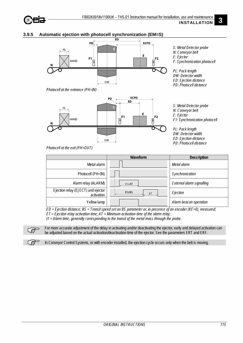
FI002K0018v1100UK – THS/21 Instruction manual for installation, use and maintenance 3 INSTALLATION
ORIGINAL INSTRUCTIONS 115
3.9.5 Automatic ejection with photocell synchronization (EM=S)
S: Metal Detector probe N: Conveyor belt E: Ejector F: Synchronization photocell PL: Pack length DW: Detector width ED: Ejection distance PD: Photocell distance
Photocell at the entrance (PH=IN)
S: Metal Detector probe N: Conveyor belt E: Ejector F1: Synchronization photocell PL: Pack length DW: Detector width ED: Ejection distance PD: Photocell distance
Photocell at the exit (PH=OUT)
Waveform Description
Metal alarm Metal alarm
Photocell (PH=IN) Synchronization
Alarm relay (ALARM) External alarm signalling
Ejection relay (EJECT) and ejector activation Ejection
Yellow lamp Alarm beacon operation
ED = Ejection distance; BS = Transit speed set on BS parameter or, in presence of an encoder (KE>0), measured; ET = Ejection relay activation time; AT = Minimum activation time of the alarm relay; t1 = Alarm time, generally corresponding to the transit of the metal mass through the probe.
For more accurate adjustment of the delay in activating and/or deactivating the ejector, early and delayed activation can be adjusted based on the actual activation/deactivation time of the ejector. See the parameters ERT and ERF.
In Conveyor Control Systems, or with encoder installed, the ejection cycle occurs only when the belt is moving.
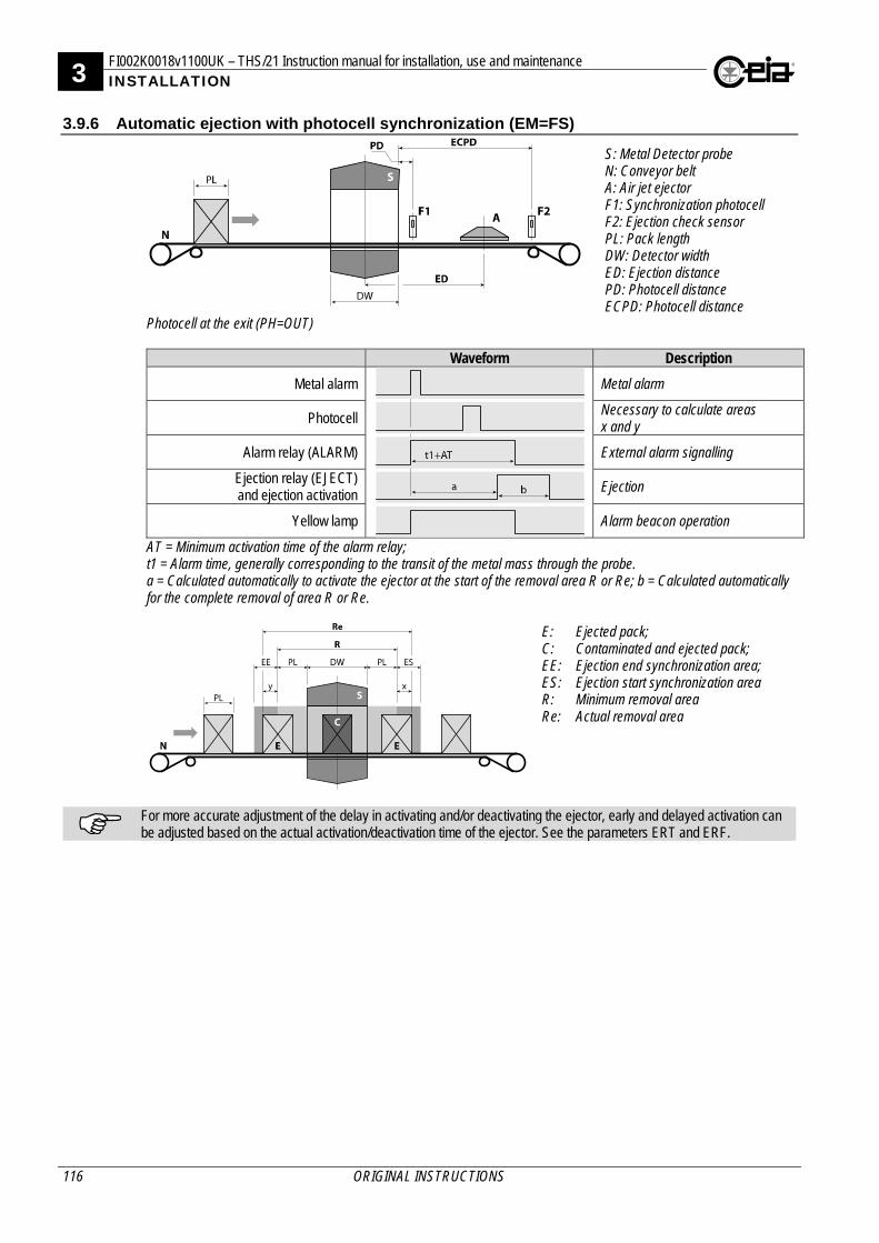
3 FI002K0018v1100UK – THS/21 Instruction manual for installation, use and maintenance INSTALLATION
116 ORIGINAL INSTRUCTIONS
3.9.6 Automatic ejection with photocell synchronization (EM=FS)
S: Metal Detector probe N: Conveyor belt A: Air jet ejector F1: Synchronization photocell F2: Ejection check sensor PL: Pack length DW: Detector width ED: Ejection distance PD: Photocell distance ECPD: Photocell distance
Photocell at the exit (PH=OUT)
Waveform Description
Metal alarm Metal alarm
Photocell Necessary to calculate areas x and y
Alarm relay (ALARM) External alarm signalling
Ejection relay (EJECT) and ejection activation
Ejection
Yellow lamp Alarm beacon operation
AT = Minimum activation time of the alarm relay; t1 = Alarm time, generally corresponding to the transit of the metal mass through the probe. a = Calculated automatically to activate the ejector at the start of the removal area R or Re; b = Calculated automatically for the complete removal of area R or Re.
E: Ejected pack; C: Contaminated and ejected pack; EE: Ejection end synchronization area; ES: Ejection start synchronization area R: Minimum removal area Re: Actual removal area
For more accurate adjustment of the delay in activating and/or deactivating the ejector, early and delayed activation can be adjusted based on the actual activation/deactivation time of the ejector. See the parameters ERT and ERF.
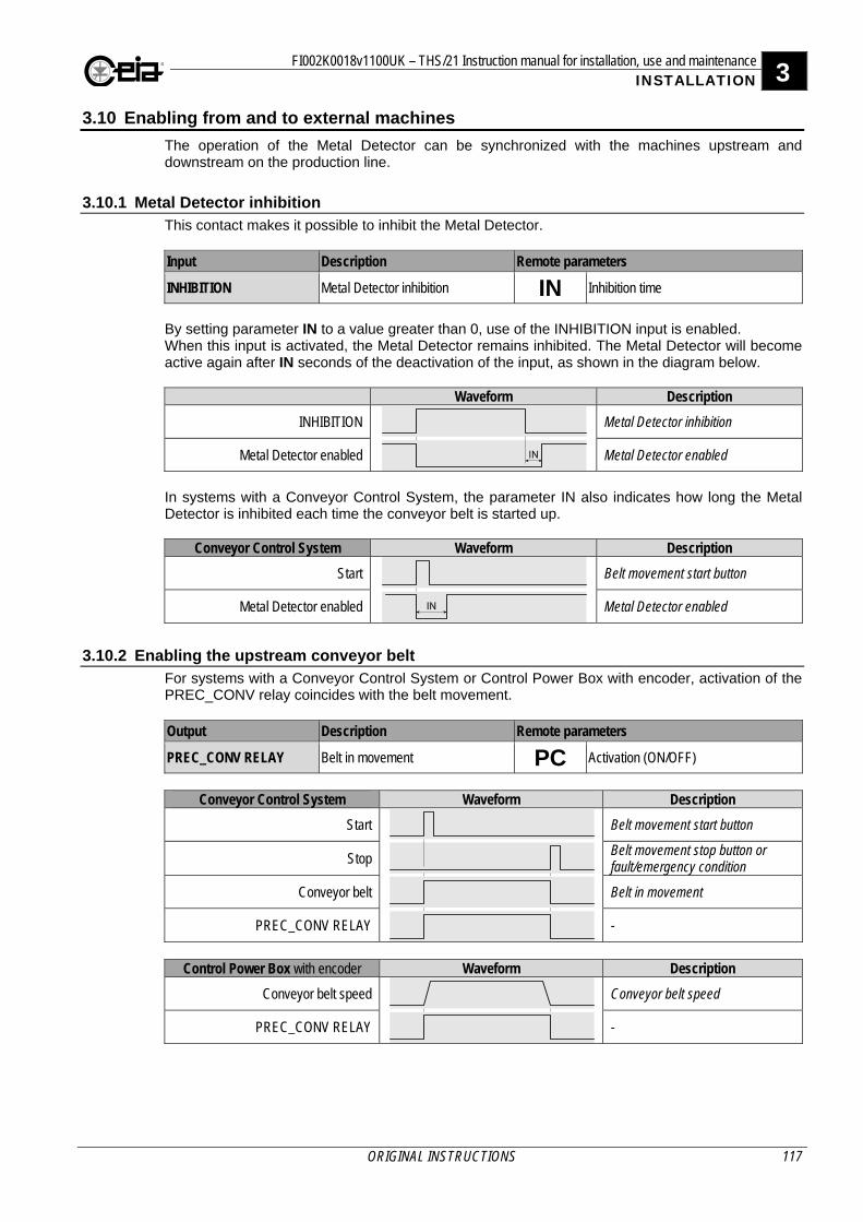
FI002K0018v1100UK – THS/21 Instruction manual for installation, use and maintenance 3 INSTALLATION
ORIGINAL INSTRUCTIONS 117
3.10 Enabling from and to external machines
The operation of the Metal Detector can be synchronized with the machines upstream and downstream on the production line.
3.10.1 Metal Detector inhibition This contact makes it possible to inhibit the Metal Detector. Input Description Remote parameters
INHIBITION Metal Detector inhibition IN Inhibition time By setting parameter IN to a value greater than 0, use of the INHIBITION input is enabled. When this input is activated, the Metal Detector remains inhibited. The Metal Detector will become active again after IN seconds of the deactivation of the input, as shown in the diagram below.
Waveform Description
INHIBITION Metal Detector inhibition
Metal Detector enabled Metal Detector enabled
In systems with a Conveyor Control System, the parameter IN also indicates how long the Metal Detector is inhibited each time the conveyor belt is started up.
Conveyor Control System Waveform Description
Start Belt movement start button
Metal Detector enabled Metal Detector enabled
3.10.2 Enabling the upstream conveyor belt For systems with a Conveyor Control System or Control Power Box with encoder, activation of the PREC_CONV relay coincides with the belt movement. Output Description Remote parameters
PREC_CONV RELAY Belt in movement PC Activation (ON/OFF)
Conveyor Control System Waveform Description
Start Belt movement start button
Stop Belt movement stop button or fault/emergency condition
Conveyor belt Belt in movement
PREC_CONV RELAY -
Control Power Box with encoder Waveform Description
Conveyor belt speed Conveyor belt speed
PREC_CONV RELAY -
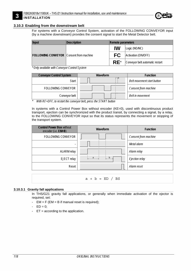
3 FI002K0018v1100UK – THS/21 Instruction manual for installation, use and maintenance INSTALLATION
118 ORIGINAL INSTRUCTIONS
3.10.3 Enabling from the downstream belt For systems with a Conveyor Control System, activation of the FOLLOWING CONVEYOR input (by a machine downstream) provides the consent signal to start the Metal Detector belt. Input Description Remote parameters
FOLLOWING CONVEYOR Consent from machine
IW Logic (NO/NC)
FC Activation (ON/OFF)
RE* Conveyor belt automatic restart * Only available with Conveyor Control System
Conveyor Control System Waveform Function
Start Belt movement start button
FOLLOWING CONVEYOR Consent from machine
Conveyor belt Belt in movement
* With RE=OFF, to restart the conveyor belt, press the START button In systems with a Control Power Box without encoder (KE=0), used with discontinuous product transport, ejection can be synchronized with the product transit, by connecting a signal, by a relay, to the FOLLOWING CONVEYOR input so that its status represents the movement or stopping of the transport system.
Control Power Box without encoder (i.e. EM=B)
Waveform Function
FOLLOWING CONVEYOR Consent from machine
- Metal alarm
ALARM relay Alarm relay
EJECT relay Ejection relay
Reset Alarm reset
a + b = ED / BS
3.10.3.1 Gravity fall applications
In THS/G21 gravity fall applications, or generally when immediate activation of the ejector is required, set:
- EM = F (EM = B if manual reset is required);
- ED = 0;
- ET = according to the application.
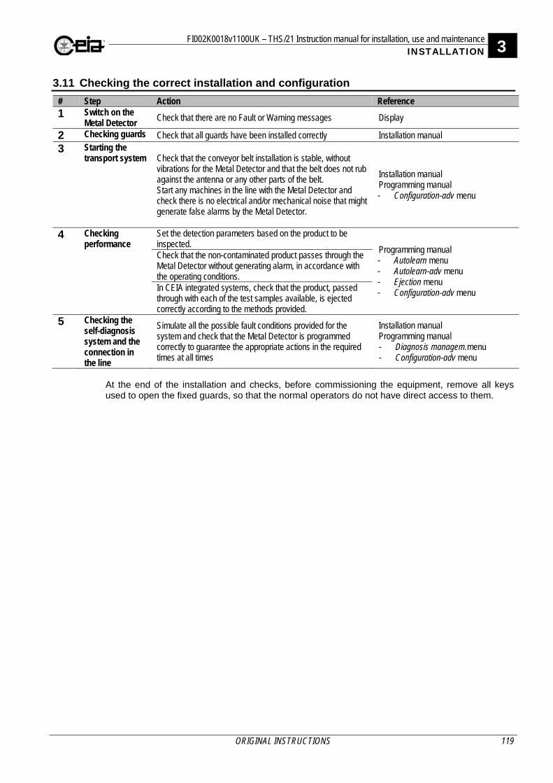
FI002K0018v1100UK – THS/21 Instruction manual for installation, use and maintenance 3 INSTALLATION
ORIGINAL INSTRUCTIONS 119
3.11 Checking the correct installation and configuration
# Step Action Reference 1 Switch on the
Metal Detector Check that there are no Fault or Warning messages Display
2 Checking guards Check that all guards have been installed correctly Installation manual
3 Starting the transport system Check that the conveyor belt installation is stable, without
vibrations for the Metal Detector and that the belt does not rub against the antenna or any other parts of the belt. Start any machines in the line with the Metal Detector and check there is no electrical and/or mechanical noise that might generate false alarms by the Metal Detector.
Installation manual Programming manual - Configuration-adv menu
4 Checking performance
Set the detection parameters based on the product to be inspected.
Programming manual - Autolearn menu - Autolearn-adv menu - Ejection menu - Configuration-adv menu
Check that the non-contaminated product passes through the Metal Detector without generating alarm, in accordance with the operating conditions. In CEIA integrated systems, check that the product, passed through with each of the test samples available, is ejected correctly according to the methods provided.
5 Checking the self-diagnosis system and the connection in the line
Simulate all the possible fault conditions provided for the system and check that the Metal Detector is programmed correctly to guarantee the appropriate actions in the required times at all times
Installation manual Programming manual - Diagnosis managem.menu - Configuration-adv menu
At the end of the installation and checks, before commissioning the equipment, remove all keys used to open the fixed guards, so that the normal operators do not have direct access to them.
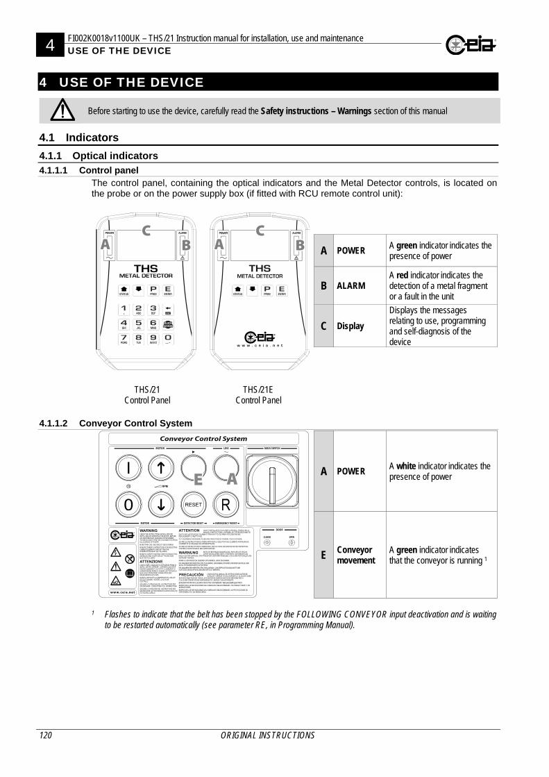
4 FI002K0018v1100UK – THS/21 Instruction manual for installation, use and maintenance USE OF THE DEVICE
120 ORIGINAL INSTRUCTIONS
4 USE OF THE DEVICE
Before starting to use the device, carefully read the Safety instructions – Warnings section of this manual
4.1 Indicators
4.1.1 Optical indicators
4.1.1.1 Control panel The control panel, containing the optical indicators and the Metal Detector controls, is located on the probe or on the power supply box (if fitted with RCU remote control unit):
A POWER A green indicator indicates the presence of power
B ALARM A red indicator indicates the detection of a metal fragment or a fault in the unit
C Display
Displays the messages relating to use, programming and self-diagnosis of the device
THS/21 Control Panel
THS/21E Control Panel
4.1.1.2 Conveyor Control System
A POWER A white indicator indicates the presence of power
E Conveyor movement
A green indicator indicates that the conveyor is running 1
1 Flashes to indicate that the belt has been stopped by the FOLLOWING CONVEYOR input deactivation and is waiting
to be restarted automatically (see parameter RE, in Programming Manual).
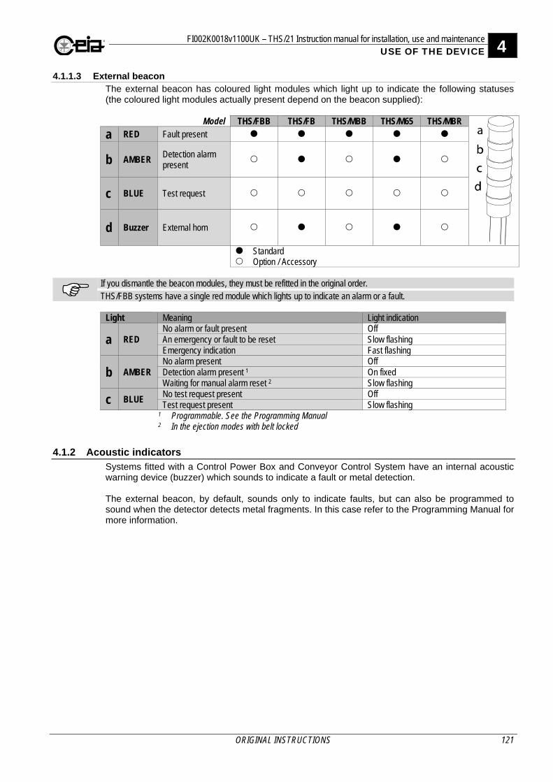
FI002K0018v1100UK – THS/21 Instruction manual for installation, use and maintenance 4 USE OF THE DEVICE
ORIGINAL INSTRUCTIONS 121
4.1.1.3 External beacon The external beacon has coloured light modules which light up to indicate the following statuses (the coloured light modules actually present depend on the beacon supplied):
Model THS/FBB THS/FB THS/MBB THS/M65 THS/MBR
a RED Fault present
b AMBER Detection alarm present
c BLUE Test request
d Buzzer External horn
Standard Option / Accessory
If you dismantle the beacon modules, they must be refitted in the original order. THS/FBB systems have a single red module which lights up to indicate an alarm or a fault. Light Meaning Light indication
a RED No alarm or fault present Off An emergency or fault to be reset Slow flashing Emergency indication Fast flashing
b AMBER No alarm present Off Detection alarm present 1 On fixed Waiting for manual alarm reset 2 Slow flashing
c BLUE No test request present Off Test request present Slow flashing
1 Programmable. See the Programming Manual 2 In the ejection modes with belt locked
4.1.2 Acoustic indicators Systems fitted with a Control Power Box and Conveyor Control System have an internal acoustic warning device (buzzer) which sounds to indicate a fault or metal detection. The external beacon, by default, sounds only to indicate faults, but can also be programmed to sound when the detector detects metal fragments. In this case refer to the Programming Manual for more information.
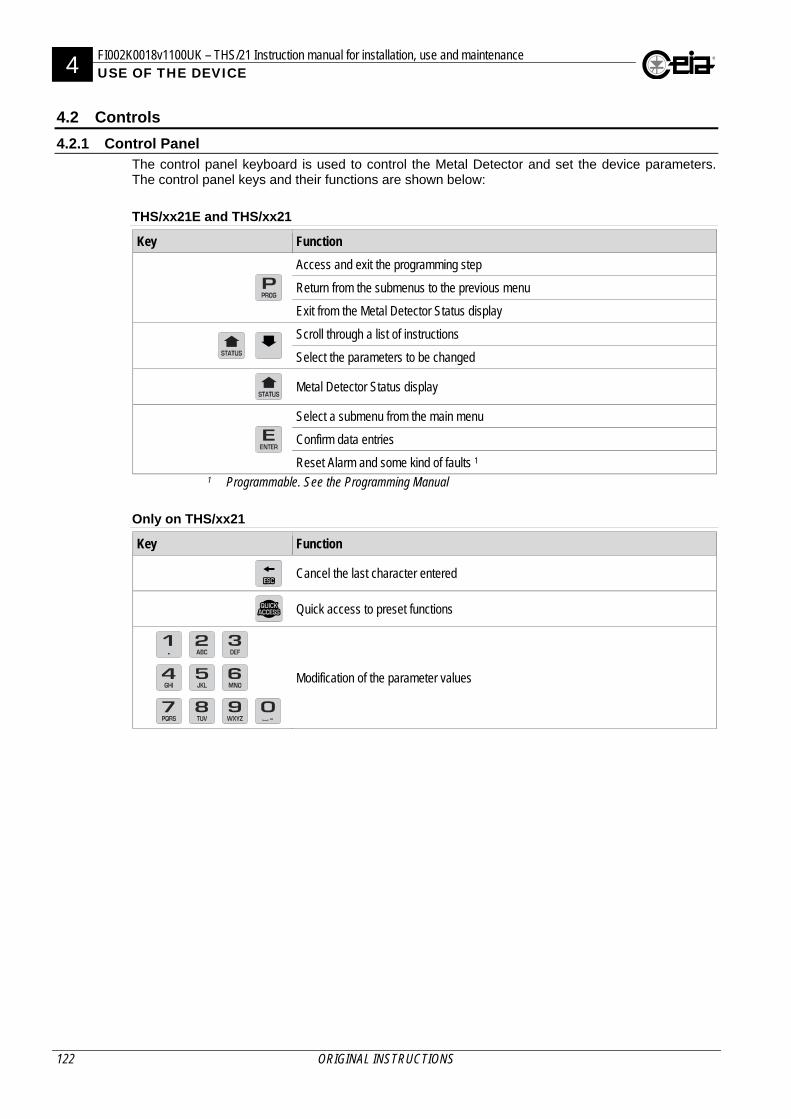
4 FI002K0018v1100UK – THS/21 Instruction manual for installation, use and maintenance USE OF THE DEVICE
122 ORIGINAL INSTRUCTIONS
4.2 Controls
4.2.1 Control Panel The control panel keyboard is used to control the Metal Detector and set the device parameters. The control panel keys and their functions are shown below:
THS/xx21E and THS/xx21
Key Function
Access and exit the programming step
Return from the submenus to the previous menu
Exit from the Metal Detector Status display
Scroll through a list of instructions
Select the parameters to be changed
Metal Detector Status display
Select a submenu from the main menu
Confirm data entries
Reset Alarm and some kind of faults 1 1 Programmable. See the Programming Manual
Only on THS/xx21
Key Function
Cancel the last character entered
Quick access to preset functions
Modification of the parameter values
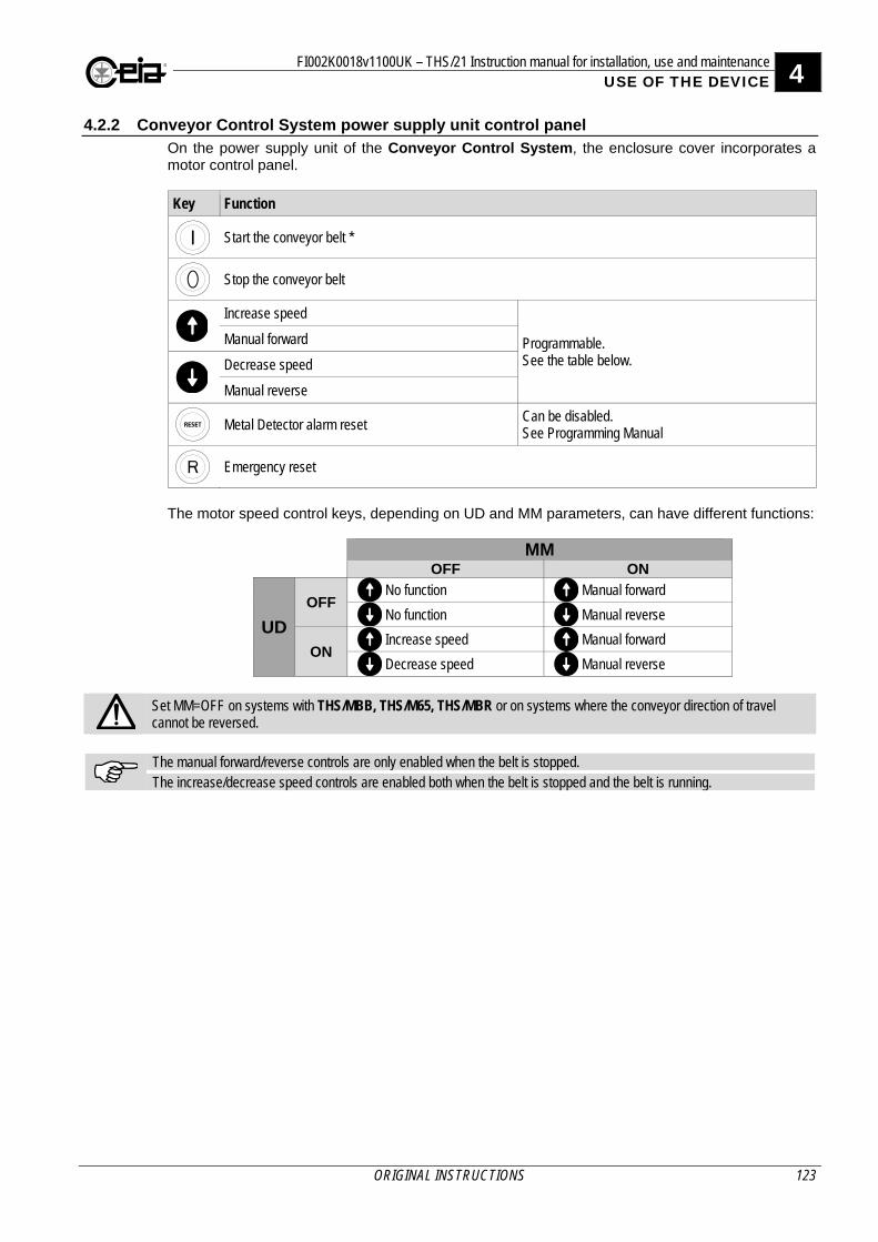
FI002K0018v1100UK – THS/21 Instruction manual for installation, use and maintenance 4 USE OF THE DEVICE
ORIGINAL INSTRUCTIONS 123
4.2.2 Conveyor Control System power supply unit control panel On the power supply unit of the Conveyor Control System, the enclosure cover incorporates a motor control panel.
Key Function
Start the conveyor belt *
Stop the conveyor belt
Increase speed
Programmable. See the table below.
Manual forward
Decrease speed
Manual reverse
Metal Detector alarm reset
Can be disabled. See Programming Manual
Emergency reset
The motor speed control keys, depending on UD and MM parameters, can have different functions:
MM OFF ON
UD
OFF No function Manual forward
No function Manual reverse
ON Increase speed Manual forward
Decrease speed Manual reverse
Set MM=OFF on systems with THS/MBB, THS/M65, THS/MBR or on systems where the conveyor direction of travel cannot be reversed.
The manual forward/reverse controls are only enabled when the belt is stopped. The increase/decrease speed controls are enabled both when the belt is stopped and the belt is running.
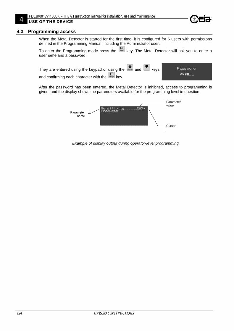
4 FI002K0018v1100UK – THS/21 Instruction manual for installation, use and maintenance USE OF THE DEVICE
124 ORIGINAL INSTRUCTIONS
4.3 Programming access
When the Metal Detector is started for the first time, it is configured for 6 users with permissions defined in the Programming Manual, including the Administrator user.
To enter the Programming mode press the key. The Metal Detector will ask you to enter a username and a password:
They are entered using the keypad or using the and keys
and confirming each character with the key.
Password
***#__
After the password has been entered, the Metal Detector is inhibited, access to programming is given, and the display shows the parameters available for the programming level in question:
Parameter
name
Parameter value
Cursor
Sensitivity~~~~~~265@ Products
Example of display output during operator-level programming
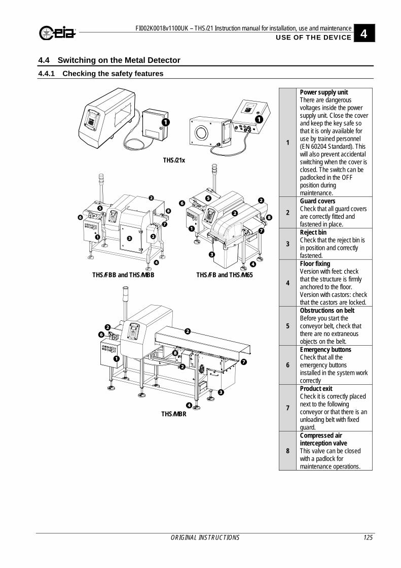
FI002K0018v1100UK – THS/21 Instruction manual for installation, use and maintenance 4 USE OF THE DEVICE
ORIGINAL INSTRUCTIONS 125
4.4 Switching on the Metal Detector
4.4.1 Checking the safety features
THS/21x
1
Power supply unit There are dangerous voltages inside the power supply unit. Close the cover and keep the key safe so that it is only available for use by trained personnel (EN 60204 Standard). This will also prevent accidental switching when the cover is closed. The switch can be padlocked in the OFF position during maintenance.
2
Guard covers Check that all guard covers are correctly fitted and fastened in place.
3
Reject bin Check that the reject bin is in position and correctly fastened.
4
Floor fixing Version with feet: check that the structure is firmly anchored to the floor. Version with castors: check that the castors are locked.
5
Obstructions on belt Before you start the conveyor belt, check that there are no extraneous objects on the belt.
6
Emergency buttons Check that all the emergency buttons installed in the system work correctly
7
Product exit Check it is correctly placed next to the following conveyor or that there is an unloading belt with fixed guard.
8
Compressed air interception valve This valve can be closed with a padlock for maintenance operations.
THS/FBB and THS/MBB
THS/FB and THS/M65
THS/MBR
11
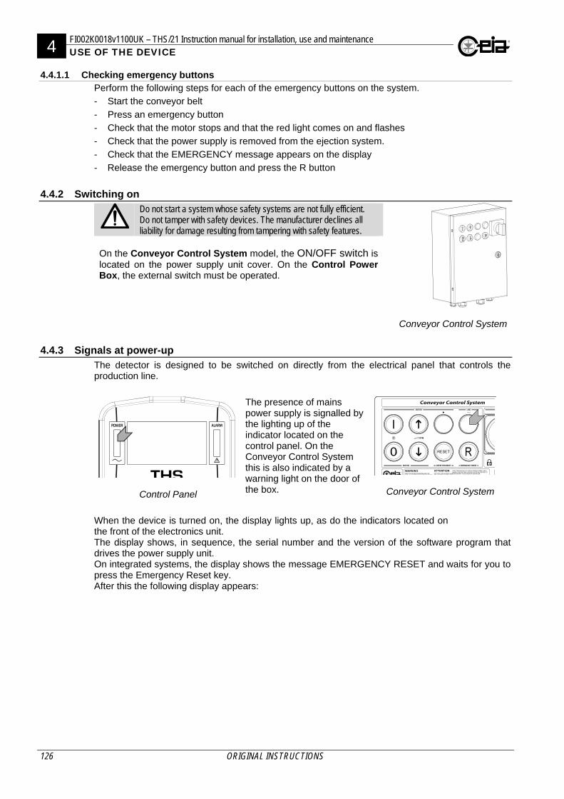
4 FI002K0018v1100UK – THS/21 Instruction manual for installation, use and maintenance USE OF THE DEVICE
126 ORIGINAL INSTRUCTIONS
4.4.1.1 Checking emergency buttons Perform the following steps for each of the emergency buttons on the system.
- Start the conveyor belt
- Press an emergency button
- Check that the motor stops and that the red light comes on and flashes
- Check that the power supply is removed from the ejection system.
- Check that the EMERGENCY message appears on the display
- Release the emergency button and press the R button
4.4.2 Switching on
Do not start a system whose safety systems are not fully efficient. Do not tamper with safety devices. The manufacturer declines all liability for damage resulting from tampering with safety features.
Conveyor Control System
On the Conveyor Control System model, the ON/OFF switch is located on the power supply unit cover. On the Control Power Box, the external switch must be operated.
4.4.3 Signals at power-up The detector is designed to be switched on directly from the electrical panel that controls the production line.
Control Panel
The presence of mains power supply is signalled by the lighting up of the indicator located on the control panel. On the Conveyor Control System this is also indicated by a warning light on the door of the box.
Conveyor Control System
When the device is turned on, the display lights up, as do the indicators located on the front of the electronics unit. The display shows, in sequence, the serial number and the version of the software program that drives the power supply unit. On integrated systems, the display shows the message EMERGENCY RESET and waits for you to press the Emergency Reset key. After this the following display appears:
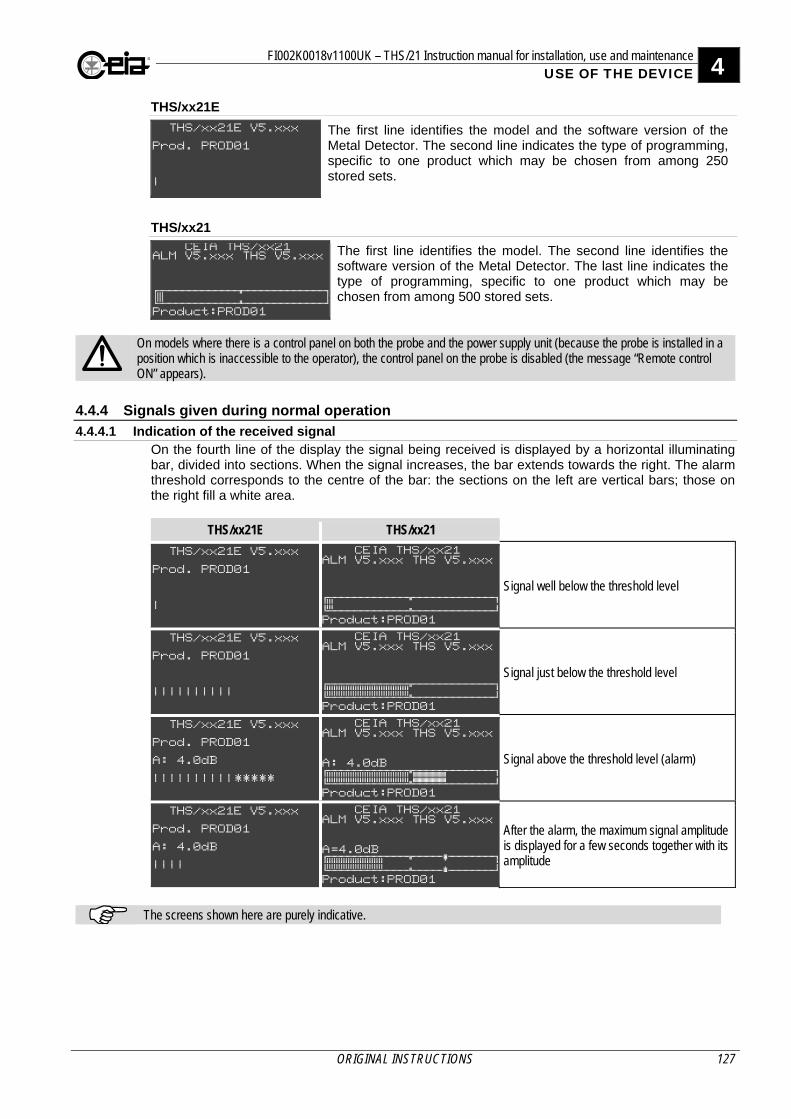
FI002K0018v1100UK – THS/21 Instruction manual for installation, use and maintenance 4 USE OF THE DEVICE
ORIGINAL INSTRUCTIONS 127
THS/xx21E
THS/xx21E V5.xxx
Prod. PROD01
^
The first line identifies the model and the software version of the Metal Detector. The second line indicates the type of programming, specific to one product which may be chosen from among 250 stored sets.
THS/xx21 CEIA THS/xx21 ALM V5.xxx THS V5.xxx
Product:PROD01
The first line identifies the model. The second line identifies the software version of the Metal Detector. The last line indicates the type of programming, specific to one product which may be chosen from among 500 stored sets.
On models where there is a control panel on both the probe and the power supply unit (because the probe is installed in a position which is inaccessible to the operator), the control panel on the probe is disabled (the message “Remote control ON” appears).
4.4.4 Signals given during normal operation
4.4.4.1 Indication of the received signal On the fourth line of the display the signal being received is displayed by a horizontal illuminating bar, divided into sections. When the signal increases, the bar extends towards the right. The alarm threshold corresponds to the centre of the bar: the sections on the left are vertical bars; those on the right fill a white area.
THS/xx21E THS/xx21
THS/xx21E V5.xxx
Prod. PROD01
^
CEIA THS/xx21 ALM V5.xxx THS V5.xxx
Product:PROD01
Signal well below the threshold level
THS/xx21E V5.xxx
Prod. PROD01
^^^^^^^^^^
CEIA THS/xx21ALM V5.xxx THS V5.xxx
Product:PROD01
Signal just below the threshold level
THS/xx21E V5.xxx
Prod. PROD01
A: 4.0dB
^^^^^^^^^^*****
CEIA THS/xx21ALM V5.xxx THS V5.xxx A: 4.0dB
Product:PROD01
Signal above the threshold level (alarm)
THS/xx21E V5.xxx
Prod. PROD01
A: 4.0dB
^^^^
CEIA THS/xx21ALM V5.xxx THS V5.xxx A=4.0dB
Product:PROD01
After the alarm, the maximum signal amplitude is displayed for a few seconds together with its amplitude
The screens shown here are purely indicative.
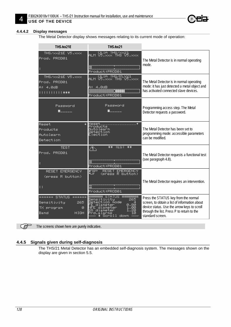
4 FI002K0018v1100UK – THS/21 Instruction manual for installation, use and maintenance USE OF THE DEVICE
128 ORIGINAL INSTRUCTIONS
4.4.4.2 Display messages The Metal Detector display shows messages relating to its current mode of operation:
THS/xx21E THS/xx21
THS/xx21E V5.xxx
Prod. PROD01
^
CEIA THS/xx21 ALM V5.xxx THS V5.xxx
Product:PROD01
The Metal Detector is in normal operating mode.
THS/xx21E V5.xxx
Prod. PROD01
A: 4.0dB
^^^^^^^^^^***
CEIA THS/PLV21 ALM V5.xxx THS V5.xxx A: 4.0dB
Product:PROD01
The Metal Detector is in normal operating mode: it has just detected a metal object and has activated connected slave devices.
Password
#_____
Password #_____
Programming access step. The Metal Detector requests a password.
Reset @
Products
Autolearn
Detection
Reset~~~~~~~~~~~~~~~@Products Autolearn Detection Ejection
The Metal Detector has been set to programming mode: accessible parameters can be modified.
TEST
Prod. PROD01
^
** TEST **
Product:PROD01
The Metal Detector requests a functional test (see paragraph 4.8).
RESET EMERGENCY
(press R button)
^^
RESET EMERGENCY (press R button)
Product:PROD01
The Metal Detector requires an intervention.
====== STATUS ======
Sensitivity 265
TX program 0
Band HIGH
[\\\\\ STATUS \\\\\\]Sensitivity 265 Detection mode 4 FE diameter 0.80 NFE diameter 1.00 SS diameter 1.20 Prd.alarms 10 {|| & Scroll down ||}
Press the STATUS key from the normal screen, to obtain a list of information about device status. Use the arrow keys to scroll through the list. Press P to return to the standard screen.
The screens shown here are purely indicative.
4.4.5 Signals given during self-diagnosis The THS/21 Metal Detector has an embedded self-diagnosis system. The messages shown on the display are given in section 5.5.
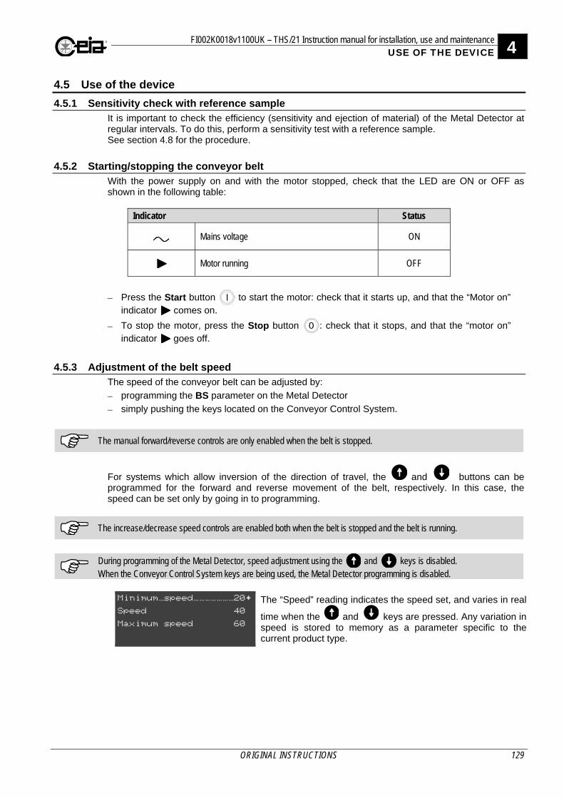
FI002K0018v1100UK – THS/21 Instruction manual for installation, use and maintenance 4 USE OF THE DEVICE
ORIGINAL INSTRUCTIONS 129
4.5 Use of the device
4.5.1 Sensitivity check with reference sample It is important to check the efficiency (sensitivity and ejection of material) of the Metal Detector at regular intervals. To do this, perform a sensitivity test with a reference sample. See section 4.8 for the procedure.
4.5.2 Starting/stopping the conveyor belt With the power supply on and with the motor stopped, check that the LED are ON or OFF as shown in the following table:
Indicator Status
Mains voltage ON
Motor running OFF
Press the Start button to start the motor: check that it starts up, and that the “Motor on” indicator comes on.
To stop the motor, press the Stop button : check that it stops, and that the “motor on” indicator goes off.
4.5.3 Adjustment of the belt speed The speed of the conveyor belt can be adjusted by:
programming the BS parameter on the Metal Detector
simply pushing the keys located on the Conveyor Control System.
The manual forward/reverse controls are only enabled when the belt is stopped.
For systems which allow inversion of the direction of travel, the and buttons can be programmed for the forward and reverse movement of the belt, respectively. In this case, the speed can be set only by going in to programming.
The increase/decrease speed controls are enabled both when the belt is stopped and the belt is running.
During programming of the Metal Detector, speed adjustment using the and keys is disabled. When the Conveyor Control System keys are being used, the Metal Detector programming is disabled.
Minimum~speed~~~~~~~20@
Speed 40
Maximum speed 60
The “Speed” reading indicates the speed set, and varies in real
time when the and keys are pressed. Any variation in speed is stored to memory as a parameter specific to the current product type.
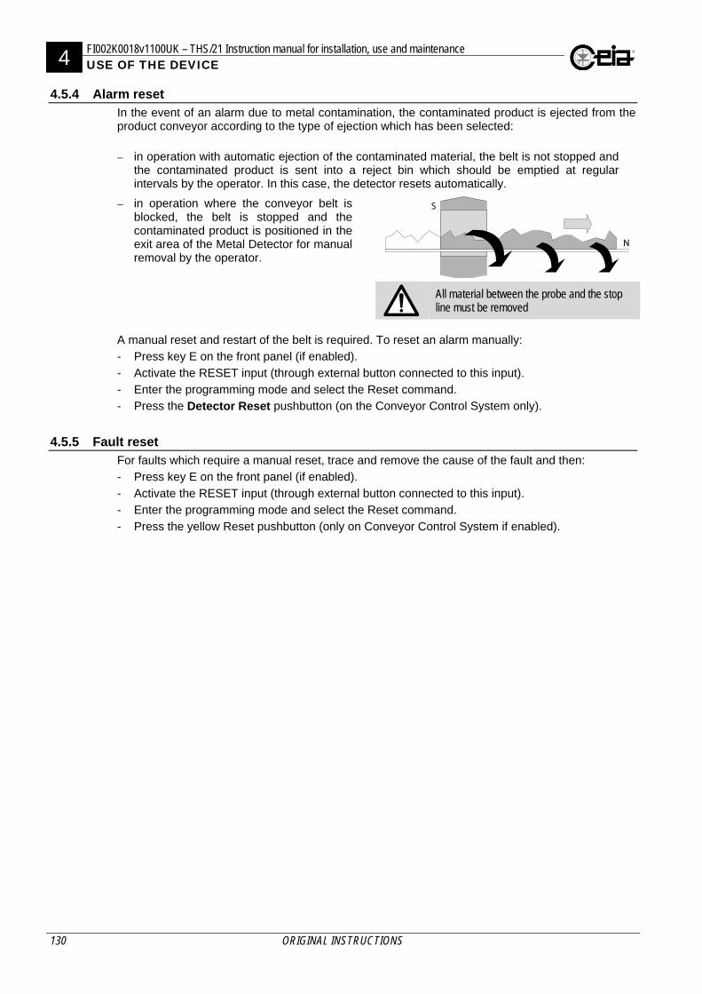
4 FI002K0018v1100UK – THS/21 Instruction manual for installation, use and maintenance USE OF THE DEVICE
130 ORIGINAL INSTRUCTIONS
4.5.4 Alarm reset In the event of an alarm due to metal contamination, the contaminated product is ejected from the product conveyor according to the type of ejection which has been selected:
in operation with automatic ejection of the contaminated material, the belt is not stopped and the contaminated product is sent into a reject bin which should be emptied at regular intervals by the operator. In this case, the detector resets automatically.
in operation where the conveyor belt is blocked, the belt is stopped and the contaminated product is positioned in the exit area of the Metal Detector for manual removal by the operator.
All material between the probe and the stop line must be removed
A manual reset and restart of the belt is required. To reset an alarm manually:
- Press key E on the front panel (if enabled).
- Activate the RESET input (through external button connected to this input).
- Enter the programming mode and select the Reset command. - Press the Detector Reset pushbutton (on the Conveyor Control System only).
4.5.5 Fault reset For faults which require a manual reset, trace and remove the cause of the fault and then:
- Press key E on the front panel (if enabled).
- Activate the RESET input (through external button connected to this input).
- Enter the programming mode and select the Reset command.
- Press the yellow Reset pushbutton (only on Conveyor Control System if enabled).
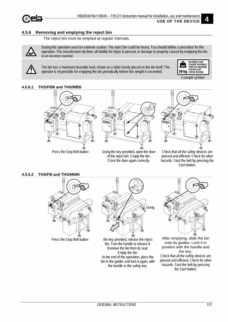
FI002K0018v1100UK – THS/21 Instruction manual for installation, use and maintenance 4 USE OF THE DEVICE
ORIGINAL INSTRUCTIONS 131
4.5.6 Removing and emptying the reject bin The reject bin must be emptied at regular intervals.
During this operation exercise extreme caution. The reject bin could be heavy. You should define a procedure for this operation. The manufacturer declines all liability for injury to persons or damage to property caused by emptying the bin in an incorrect manner.
The bin has a maximum bearable load, shown on a label clearly placed on the bin itself. The operator is responsible for emptying the bin periodically before this weight is exceeded.
Example of label
4.5.6.1 THS/FBB and THS/MBB
Press the Stop Belt button
Using the key provided, open the door
of the reject bin. Empty the bin. Close the door again correctly.
Check that all the safety devices are present and efficient. Check for other hazards. Start the belt by pressing the
Start button.
4.5.6.2 THS/FB and THS/M69K
Press the Stop Belt button
Using
the key provided, release the reject bin. Turn the handle to release it.
Remove the bin from its seat. Empty the bin.
At the end of the operation, place the bin in the guides and lock it again, with
the handle or the safety key.
After emptying, slide the bin
onto its guides. Lock it in position with the handle and
the key. Check that all the safety devices are present and efficient. Check for other
hazards. Start the belt by pressing the Start button.
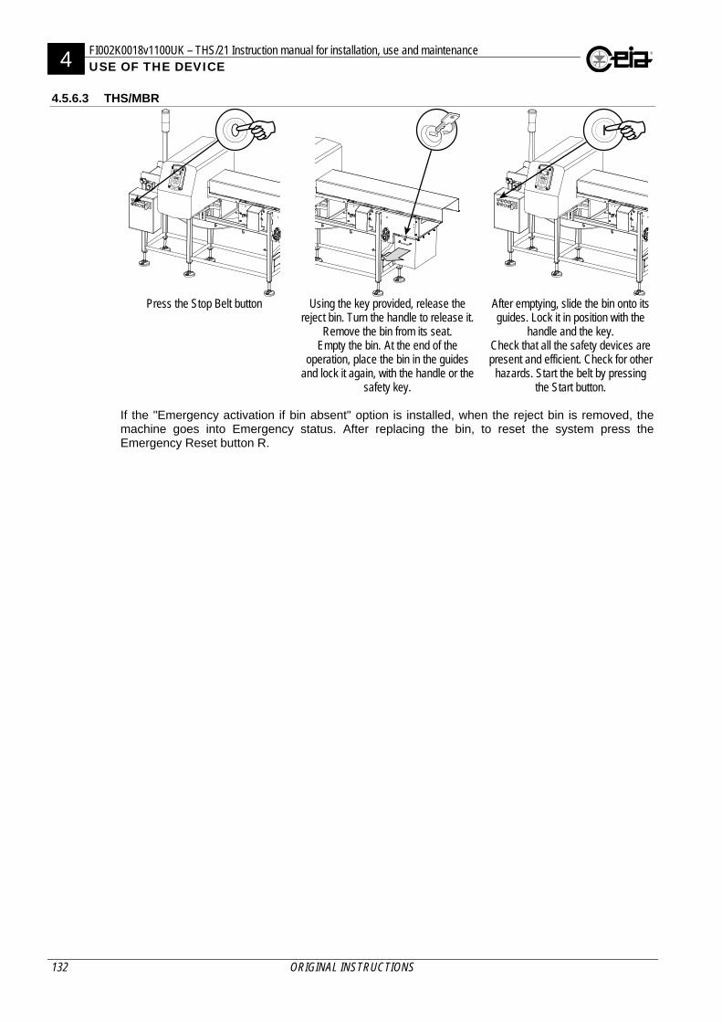
4 FI002K0018v1100UK – THS/21 Instruction manual for installation, use and maintenance USE OF THE DEVICE
132 ORIGINAL INSTRUCTIONS
4.5.6.3 THS/MBR
Press the Stop Belt button
Using the key provided, release the
reject bin. Turn the handle to release it. Remove the bin from its seat.
Empty the bin. At the end of the operation, place the bin in the guides
and lock it again, with the handle or the safety key.
After emptying, slide the bin onto its guides. Lock it in position with the
handle and the key. Check that all the safety devices are present and efficient. Check for other
hazards. Start the belt by pressing the Start button.
If the "Emergency activation if bin absent" option is installed, when the reject bin is removed, the machine goes into Emergency status. After replacing the bin, to reset the system press the Emergency Reset button R.

FI002K0018v1100UK – THS/21 Instruction manual for installation, use and maintenance 4 USE OF THE DEVICE
ORIGINAL INSTRUCTIONS 133
4.5.7 Automatic stop
This function is only available on the Conveyor Control System.
The conveyor belt is automatically stopped in the following cases:
Self-diagnosis status
If there are self-diagnosis messages, the conveyor belt stops automatically.
It is possible to disable the belt stop if there are self-diagnosis messages. However, the READY relay is deactivated. See the Programming Manual (SF parameter).
Pressing an emergency button
There are several emergency buttons on the conveyor belt and if one of them is pressed the conveyor belt stops immediately. The external optical signalling device shows the amber light flashing slowly.
If necessary, the main system switch can also be used for this purpose.
RESET EMERGENCY (press R button)
Product:PROD01
Trace and remove the cause of the emergency stop and then reset the system by pressing the Emergency Reset key
Disabling from an external machine
Activation of the FOLLOWING CONVEYOR input from an external machine connected to it, causes the conveyor belt to stop immediately.
Automatic stop due to absence of product in transit
On systems fitted with a synchronizing photocell, it is possible to set the conveyor belt to stop automatically if nothing passes through the Metal Detector for a certain length of time. See parameter ST on Programming Manual.
4.6 Programming
For all programming operations, modifications of installation parameters, local and remote control, see the Programming Manual, shipped with the present manual.
4.7 Programming the Metal Detector according to the product type
See paragraph 2.8 of the Programming Manual.
4 FI002K0018v1100UK – THS/21 Instruction manual for installation, use and maintenance USE OF THE DEVICE
134 ORIGINAL INSTRUCTIONS
4.8 Sensitivity check with reference sample
It is important to check at regular intervals that the Metal Detector is operating efficiently. This is done by running a detection and ejection test using test reference samples.
- Depending on product characteristics and/or internal quality procedures, customers can use samples they have defined themselves or request specific samples from CEIA.
- The tests can be carried out at any time deemed necessary (e.g. at the shift changeover) and/or pre-programmed. In the latter case, the Metal Detector will automatically request the test.
It is possible to test the detection capability of the Metal Detector by selecting the DEFAULT product mode and using the reference samples indicated in the Factory Acceptance test (FAT).
4.8.1 Programming the request frequency of the periodic tests
- Select the time between the system power-on and the first test request, through the 1st test delay parameter (FTD, see Q-C setup menu).
- Select the time between one test and another, through the Test period parameter (TE, see Q-C setup menu).
Example: Setting a test period of 2 hours and a 1st test delay of 5 minutes, switching on the system at 08:22, the first test will be requested at 08:27 and subsequent tests will be requested at 10:27, 12:27, 14:27 and so on. At each Metal Detector start-up, the first test will be requested after 5 minutes and the subsequent tests every 2 hours, starting from the first request.
To disable periodic test requests, set the parameter Test period = 00:00. - Set the waiting period for carrying out the test via the Test delay parameter (TD, see Q-C
setup).
- Where required you can set the other parameters involved in the test (TMD, SAC, STM).
4.8.2 Performing tests
For the programmed tests, at the end of the Test period, a message requesting a test is displayed. At the same time the external blue lamp is activated (BLUE LAMP output).
TEST
Prod. PROD01
^
** TEST **
Product:PROD01
The test can be started by the Quality Control Operator or the Quality Control Supervisor (and in any case by an authorized user).
If the periodic test is started beyond the maximum time TD since it was requested, the TEST TIME OUT message is displayed. The diagnostics status may be activated in accordance with the FT parameter (see the Programming Manual).
FI002K0018v1100UK – THS/21 Instruction manual for installation, use and maintenance 4 USE OF THE DEVICE
ORIGINAL INSTRUCTIONS 135
4.8.2.1 Test procedure The procedure below describes a test with a ferrous sample; the other two samples, made from non-ferrous metal and in stainless steel, follow the same procedure. For the double and the triple test (see TMD on Programming Manual), the tests will be requested one after the other. The execution of the tests and the final response will be recorded in the event log.
THS/21E THS/21
To perform the Metal Detector test (independently or in response to the automatic request), select MD Test > FE test and press E key.
FE test -0.80 @
NFE test-1.00
SS test -1.20
FE~test~-0.80~~~~~~~@NFE test-1.00 SS test -1.20
Wait a few seconds, before performing the sample transit.
=====================
WAIT
---------------------
[\\\\\\\\\\\\\\\\\\\] WAIT
{|||||||||||||||||||}
Pass the requested sample, together with the pure product, through the probe within 1 minute.
=====================
PASSE FE SAMPLE
---------------------
[\\\\\\\\\\\\\\\\\\\] PASS FE SAMPLE
{|||||||||||||||||||}
If the sample is correctly detected and ejected (through the Ejection Confirmation check), the test is successful.
=====================
TEST PASSED
---------------------
[\\\\\\\\\\\\\\\\\\\] TEST PASSED
{|||||||||||||||||||}
Pressing any key, the display returns to the MD test menu, where the positive outcome is also shown.
FE test -0.80 OK
NFE test-1.00
SS test -1.20
FE~test~-0.80~~~~~OKNFE test-1.00 SS test -1.20
Repeat the test with the non-ferrous and stainless steel samples. If the test is unsuccessful, one of the following messages will be seen:
TEST FAILED for Sample not detected
THS/21E THS/21
If the sample is not detected it could be that the transit was performed in the 20 seconds immediately after the request, or the sample signal is lower than the alarm threshold.
=====================
TEST FE FAILED
NO SAMPLE DETECTED
---------------------
[\\\\\\\\\\\\\\\\\\\] TEST FE FAILED NO SAMPLE DETECTED
{|||||||||||||||||||}
Pressing any key, the display returns to the MD test menu, where the negative outcome is also shown.
FE test -0.80 NO(1)@
NFE test-1.00
SS test -1.20
1- NO SAMPLE DETECTED
FE~Test~-0.80~~NO(1)@NFE Test-1.00 SS test -1.20 1- NO SAMPLE DETECTED
4 FI002K0018v1100UK – THS/21 Instruction manual for installation, use and maintenance USE OF THE DEVICE
136 ORIGINAL INSTRUCTIONS
TEST FAILED for Sample too big
THS/21E THS/21
The signal given by the sample is considered too high to perform a valid test, according to SAC settings (see Programming Manual).
=====================
TEST FE FAILED
SAMPLE TOO BIG
---------------------
[\\\\\\\\\\\\\\\\\\\] TEST FE FAILED SAMPLE TOO BIG
{|||||||||||||||||||}
Pressing any key, the display returns to the MD test menu, where the negative outcome is also shown.
FE test -0.80 NO(2)@
NFE test-1.00
SS test -1.20
2- SAMPLE TOO BIG
FE~Test~-0.80~~NO(2)@NFE Test-1.00 SS test -1.20 2- SAMPLE TOO BIG
TEST FAILED for Ejection not confirmed
THS/21E THS/21
If the sample is correctly detected, but there is not any confirmation of its ejection, the test is considered to be unsuccessful.
=====================
TEST FE FAILED
EJECT.NOT CONFIRM
---------------------
[\\\\\\\\\\\\\\\\\\\] TEST FE FAILED EJECT.NOT CONFIRM
{|||||||||||||||||||}
Pressing any key, the display returns to the MD test menu, where the negative outcome is also shown.
FE test -0.80 NO(3)@
NFE test-1.00
SS test -1.20
3- EJECT.NOT CONFIRM
FE~Test~-0.80~~NO(3)@NFE Test-1.00 SS test -1.20 3- EJECT.NOT CONFIRM
TEST FAILED for Ejection timeout
THS/21E THS/21
If the ejection cycle is not completed following an alarm within a minute of starting the test, the test is considered to be unsuccessful.
=====================
TEST FE FAILED
EJECTION TIMEOUT
---------------------
[\\\\\\\\\\\\\\\\\\\] TEST FE FAILED EJECTION TIMEOUT
{|||||||||||||||||||}
Pressing any key, the display returns to the MD test menu, where the negative outcome is also shown.
FE test -0.80 NO(3)@
NFE test-1.00
SS test -1.20
3- EJECTION TIMEOUT
FE~Test~-0.80~~NO(3)@NFE Test-1.00 SS test -1.20 3- EJECTION TIMEOUT
TEST FAILED for synchronization photocell error
THS/21E THS/21
In the FS ejection mode, if the synchronization photocell is not activated following an alarm during the test, the test is considered to be unsuccessful.
=====================
TEST FE FAILED
SYNC PHOTOC.ERROR
---------------------
[\\\\\\\\\\\\\\\\\\\] TEST FE FAILED SYNC PHOTOC.ERROR
{|||||||||||||||||||}
Pressing any key, the display returns to the MD test menu, where the negative outcome is also shown.
FE test -0.80 NO(3)@
NFE test-1.00
SS test -1.20
3- SYNC PHOTOC.ERROR
FE~Test~-0.80~~NO(3)@NFE Test-1.00 SS test -1.20 3- SYNC PHOTOC.ERROR
FI002K0018v1100UK – THS/21 Instruction manual for installation, use and maintenance 4 USE OF THE DEVICE
ORIGINAL INSTRUCTIONS 137
TEST ABORTED
If the self-diagnosis system detects a fault of any kind, the test procedure will be interrupted and the message shown here will be displayed. In this case, the “REMOVE FAULT CONDITIONS” message warns that the test cannot be repeated without first resetting the system.
THS/21E THS/21
=====================
TEST ABORTED
---------------------
FE~Test~-0.80~~NO(1)@NFE Test-1.00 [\\\\\\\\\\\\\\\\\\\]
TEST ABORTED
{|||||||||||||||||||}
The test can also be interrupted by pressing P during the test.
In the event of an unsuccessful test, the message “TEST FAILED” is shown and the fault condition may be activated according to the FF parameter (see Programming Manual). The system can be set so that, after resetting, the test must be performed successfully (see the STM parameter in the Programming Manual).
4.8.3 Quick test You can run a single test without having to enter the programming mode. This is done by enabling the input IN_AUX1 (for example with a pushbutton connected to it). Select the test by selecting the QCKT parameter in the QA Configuration menu. When you activate the input, the display will show a message requesting the corresponding test. Run the test by passing the sample through the unit in the manual mode. The result of the test will be recorded as usual in the event log as a Quick Test.
4 FI002K0018v1100UK – THS/21 Instruction manual for installation, use and maintenance USE OF THE DEVICE
138 ORIGINAL INSTRUCTIONS
4.9 Settings for CFR21 Standards
4.9.1 General information The U.S. Code of Federal Regulations, CFR Title 21, Volume 1 – Part 11 “Electronic Records; Electronic Signatures” contains a series of requirements for the secure and reliable management of electronic records, electronic signatures and for accessing, reading and processing the stored data. The requirements contained in the regulation can be grouped into two categories:
- Requirements applicable to the intrinsic operation and to the programming of the equipment under test (in this case the Pharmaceutical Metal Detector THS/PH21N®).
- Requirements that govern correct management and organization by the user, so as to comply completely with the regulation in question.
The complete range of procedures applied by the user and applied to the operational characteristics of the Metal Detector must guarantee complete compliance with the regulation.
4.9.2 Metal Detector settings In order to ensure compliance with CFR21 standards you should note the following:
- All users working with the Metal Detector must have their own username and password. This management shall be performed according to CFR21 standards. Direct access to any of the programming menus, without a password (user 000000), must not be available. The Administrator must periodically change the passwords of all operators.
- Set the Restricted access (FLR) parameter to ON, to prevent any access by unauthorized
personnel.
- In the case of remote programming, without the IXC card, check that the way to access remote programming will be treated as per local programming, setting RS232Password (RM) and AuxRS232passw (AURM) to “NULL”. Also check that the automatic exit from remote programming is set (RPTO = ON).
- Set the Event buffer fault parameter (FB) to ON, to prevent loss of stored data and events not yet printed or saved.
- All production data must be printed and/or saved and stored separately, on a regular basis and managed according to CFR21 standards. This can be easily performed using THS Production software.
- The saved data can be validated using the THS Production software, or by connecting to the site http://www.ceia.it/cfr21validation, selecting the file to be analysed and pressing the “Check Digital Signature” button.
If the file is not valid (incomplete data or data partially modified), the message “Invalid Digital Signature” is shown: in this case, the relevant data needs to be saved again.
FI002K0018v1100UK – THS/21 Instruction manual for installation, use and maintenance 5 MAINTENANCE
ORIGINAL INSTRUCTIONS 139
5 MAINTENANCE
Before starting any installation operation, carefully read the Safety instructions – Warnings section of this manual.
Any maintenance or repair of the device while open and powered up should be avoided and in any case should only be carried out by trained personnel who are fully aware of the risks which the operation entails, following the instructions given in the Maintenance section.
When the mains is disconnected using the main switch of the Conveyor Control System, the power supply section is deactivated, but any contacts which can be connected to the mains, e.g. the relay outputs, remain energized.
5.1 Periodic Maintenance
The following is a list of maintenance operations and their suggested frequency.
Operation Frequency Operator Procedure
Preventive maintenance At the beginning of each shift
Operator Visual check of the integrity of the components and check of safety components – Par.4.4.1
On changing product type Periodically
Emptying the reject bin Periodically Operator Par. 4.5.6
Detection check At the beginning of each shift Quality control
operator; Head of quality control
Section 4.8.2 On changing product type Periodically
Checking the bearings
Periodically Operator Visual check of bearing efficiency and lack of lubricant leaks.
Monthly (wet environments subject to frequent washing) Maintenance personnel Grease where specified 6 months (dry environments)
Cleaning At the beginning of each shift Operator
Section 5.2.1 On changing product type Operator
Periodically Cleaning the conveyor belt When needed Operator Section 5.2.2 Emptying the compressed air filter container When needed Operator
Conveyor belt tension adjustment (THS/FBB and THS/FB) 6 months or when needed Maintenance personnel Section 5.2.3
Locking terminals used to connect control panels
6 months Maintenance personnel
Tightening the screws 6 months Maintenance personnel
The operator must monitor the condition of the system and its suitability for use and consult the maintenance personnel if necessary.
5.2 Periodic Maintenance procedures
5.2.1 External cleaning instructions Only use products compatible with stainless steel (AISI 316), PETG and silicon. Use a slightly damp, non-abrasive cloth
Do NOT use HYDROCHLORIC ACID or its solutions.
Do NOT use any other cleaning procedure.
.
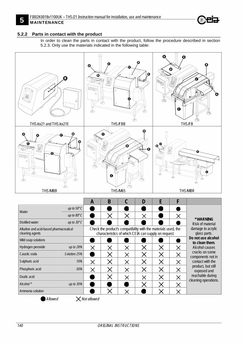
5 FI002K0018v1100UK – THS/21 Instruction manual for installation, use and maintenance MAINTENANCE
140 ORIGINAL INSTRUCTIONS
5.2.2 Parts in contact with the product In order to clean the parts in contact with the product, follow the procedure described in section 5.2.3. Only use the materials indicated in the following table:
THS/xx21 and THS/xx21E
THS/FBB
THS/FB
THS/MBB
THS/M65
THS/MBR
A B C D E F
Water up to 50°C
* WARNING Risk of material
damage to acrylic glass parts.
Do not use alcohol to clean them. Alcohol causes cracks on some
components not in contact with the product, but still
exposed and reachable during
cleaning operations.
up to 80°C Distilled water up to 30°C Alkaline and acid-based pharmaceutical cleaning agents
Check the product's compatibility with the materials used, the characteristics of which CEIA can supply on request
Mild soap solutions Hydrogen peroxide up to 28% Caustic soda Solution 25% Sulphuric acid 10% Phosphoric acid 50% Oxalic acid Alcohol * up to 30% Ammonia solution
Allowed Not allowed
B
A E
B
A
D
C
C
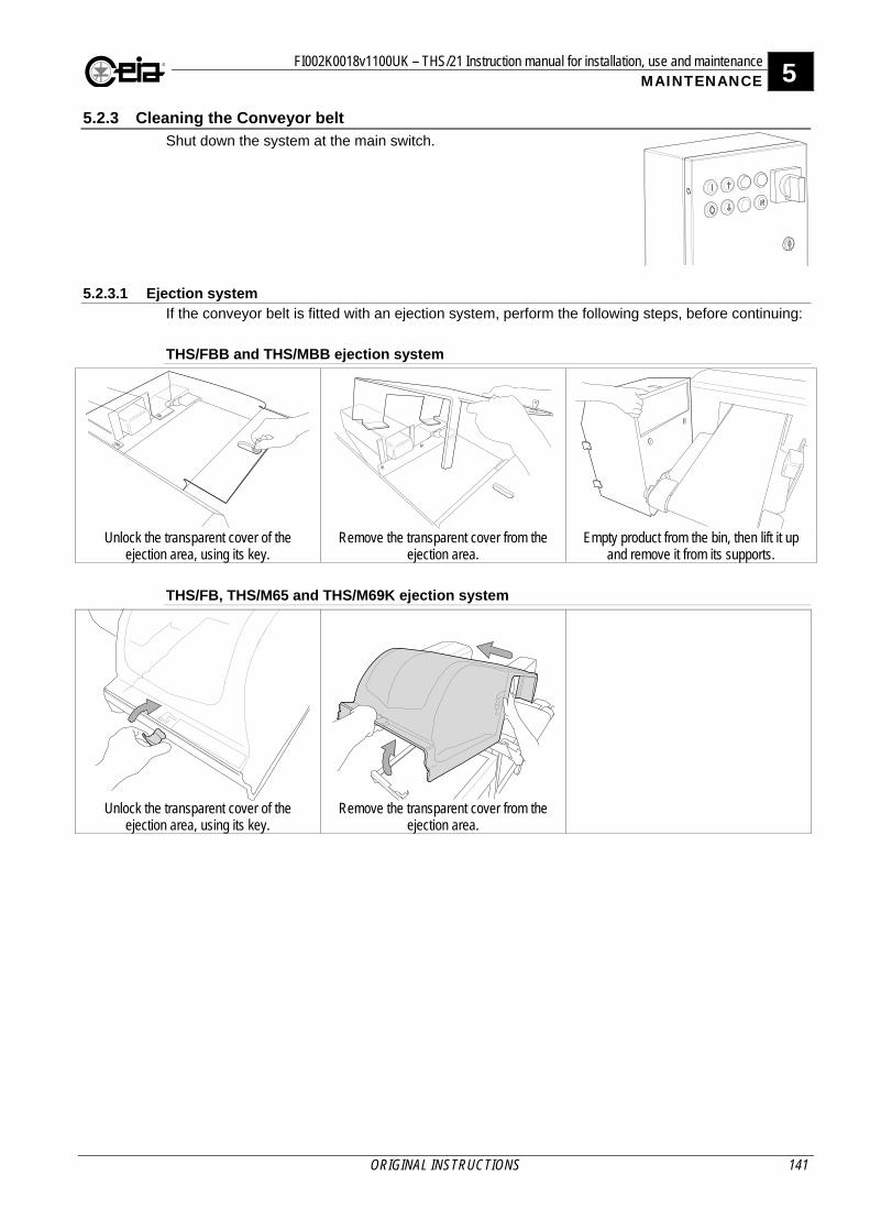
FI002K0018v1100UK – THS/21 Instruction manual for installation, use and maintenance 5 MAINTENANCE
ORIGINAL INSTRUCTIONS 141
5.2.3 Cleaning the Conveyor belt Shut down the system at the main switch.
5.2.3.1 Ejection system
If the conveyor belt is fitted with an ejection system, perform the following steps, before continuing:
THS/FBB and THS/MBB ejection system
Unlock the transparent cover of the
ejection area, using its key. Remove the transparent cover from the
ejection area. Empty product from the bin, then lift it up
and remove it from its supports.
THS/FB, THS/M65 and THS/M69K ejection system
Unlock the transparent cover of the ejection area, using its key.
Remove the transparent cover from the ejection area.
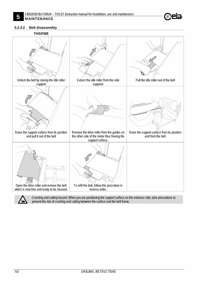
5 FI002K0018v1100UK – THS/21 Instruction manual for installation, use and maintenance MAINTENANCE
142 ORIGINAL INSTRUCTIONS
5.2.3.2 Belt disassembly
THS/FBB
Unlock the belt by raising the idle roller
support Extract the idle roller from the side
supports Pull the idle roller out of the belt
Raise the support surface from its position
and pull it out of the belt Remove the drive roller from the guides on the other side of the motor thus freeing the
support surface.
Raise the support surface from its position and from the belt
Open the drive roller and remove the belt
which is now free and ready to be cleaned. To refit the belt, follow this procedure in
reverse order.
Crushing and cutting hazard. When you are positioning the support surface on the entrance side, take precautions to prevent the risk of crushing and cutting between the surface and the belt frame.
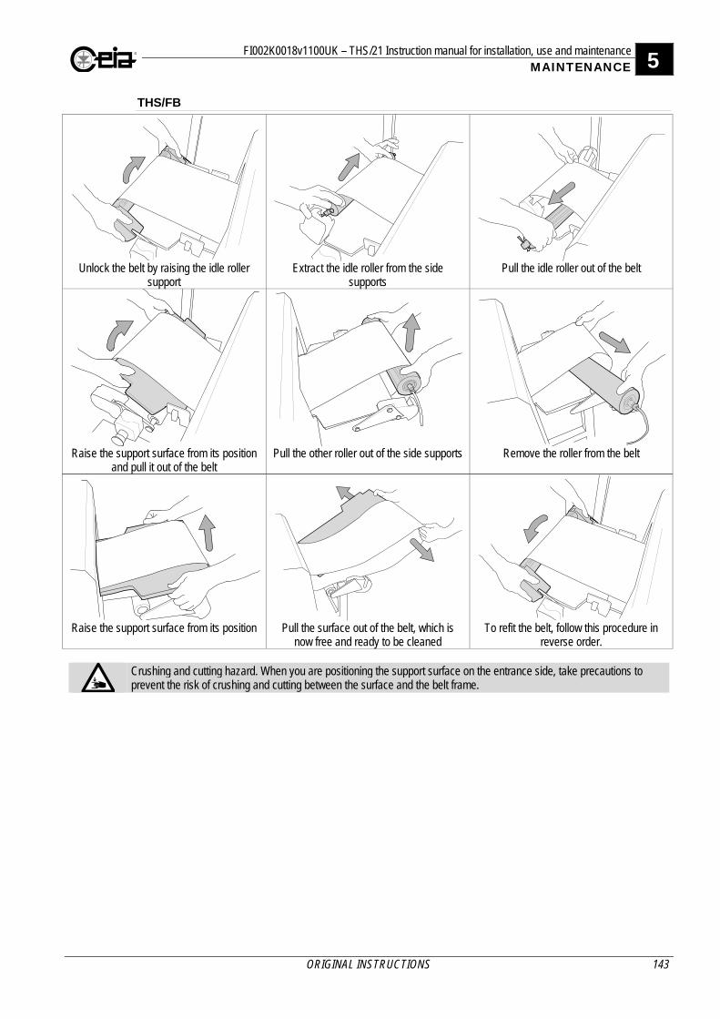
FI002K0018v1100UK – THS/21 Instruction manual for installation, use and maintenance 5 MAINTENANCE
ORIGINAL INSTRUCTIONS 143
THS/FB
Unlock the belt by raising the idle roller
support Extract the idle roller from the side
supports Pull the idle roller out of the belt
Raise the support surface from its position
and pull it out of the belt Pull the other roller out of the side supports Remove the roller from the belt
Raise the support surface from its position Pull the surface out of the belt, which is
now free and ready to be cleaned To refit the belt, follow this procedure in
reverse order.
Crushing and cutting hazard. When you are positioning the support surface on the entrance side, take precautions to prevent the risk of crushing and cutting between the surface and the belt frame.
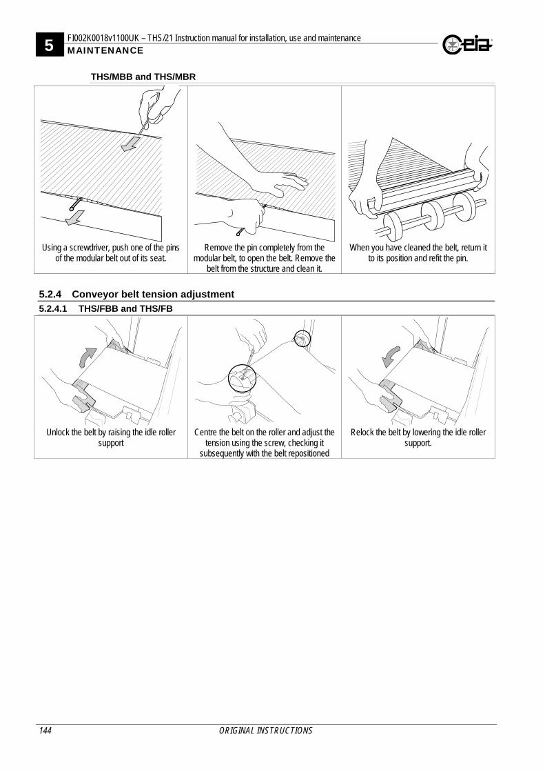
5 FI002K0018v1100UK – THS/21 Instruction manual for installation, use and maintenance MAINTENANCE
144 ORIGINAL INSTRUCTIONS
THS/MBB and THS/MBR
Using a screwdriver, push one of the pins
of the modular belt out of its seat. Remove the pin completely from the
modular belt, to open the belt. Remove the belt from the structure and clean it.
When you have cleaned the belt, return it to its position and refit the pin.
5.2.4 Conveyor belt tension adjustment
5.2.4.1 THS/FBB and THS/FB
Unlock the belt by raising the idle roller
support Centre the belt on the roller and adjust the
tension using the screw, checking it subsequently with the belt repositioned
Relock the belt by lowering the idle roller support.
FI002K0018v1100UK – THS/21 Instruction manual for installation, use and maintenance 5 MAINTENANCE
ORIGINAL INSTRUCTIONS 145
5.3 Troubleshooting
All the power supply voltages in the power supply card are protected by self-resetting fuses which can be activated if there is an overload or faulty connection, for the voltage values on the card, except for the mains voltage. Refer to the description of the inputs and outputs. The THS systems have a self-diagnosis system which displays error messages, strictly related to the operation of the Metal Detector or to controls activated on the system input lines. For these messages, refer to the Self-diagnosis section. For fault conditions not indicated because of faulty electrical installation or configuration of the Metal Detector, see the following tables:
The control panel display is not on
Green and red indicators off, internal siren activated
Check that the SCD card is correctly connected to the ALM card. If the problem persists, contact Assistance Service.
Green and red indicators off, internal siren not activated
If the Metal Detector is capable of expelling metal masses, check that the RCU card is correctly connected to the ALM card; otherwise check the state of fuse F10 (and F11/F12 for Conveyor Control System) and that the power supply voltage is within the permitted range.
Green and red indicators on
Check the connections between the SCD card and the ALM card. Disconnect all the devices connected, switch off the system and switch it on again after a few minutes, if self-resetting protective devices have been activated. If the problem persists, contact Assistance Service.
The Metal Detector does not provide alarms when test samples are used
Sample does not have the right diameter for the current product
Set the default product and create a new one. Check that the samples are detected, if necessary by increasing the sensitivity value. If they are detected, samples with a bigger diameter must be used for the current product; otherwise contact Assistance Service.
Incorrect detection parameters for current product
Check that the correct product has been selected; otherwise repeat the Autolearn procedure for the product setting automatic selection of sensitivity and, for THS/xMS21 or THS/3F systems, automatic selection of the detection mode or band, respectively. For Control Power Box systems without an encoder, check that the product transit speed is compatible with the corresponding parameters set.
The Metal Detector provides false alarms without the passage of the product
Electrical or mechanical disturbances With the settings for normal operating conditions, perform the Environmental Compatibility Check procedure. If the source of the disturbance is not identified, see below.
Metal Detector malfunction
Disconnect all the devices connected to the Metal Detector. If possible, connect it to a different power supply and earth source, in an atmosphere free of possible sources of interference. If the disturbance remains the same, contact Assistance Service.
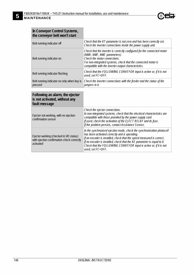
5 FI002K0018v1100UK – THS/21 Instruction manual for installation, use and maintenance MAINTENANCE
146 ORIGINAL INSTRUCTIONS
In Conveyor Control Systems, the conveyor belt won't start
Belt running indicator off Check that the KT parameter is not zero and has been correctly set. Check the inverter connections inside the power supply unit.
Belt running indicator on
Check that the inverter is correctly configured for the connected motor (NMV, NMF, NMC parameters). Check the motor connections. For non-integrated systems, check that the connected motor is compatible with the inverter output characteristics.
Belt running indicator flashing Check that the FOLLOWING CONVEYOR input is active or, if it is not used, set FC=OFF.
Belt running indicator on only when key is pressed
Check the inverter connections with the feeder and the status of the jumpers in it.
Following an alarm, the ejector is not activated, without any fault message
Ejector not working, with no ejection confirmation sensor
Check the ejector connections. In non-integrated systems, check that the electrical characteristics are compatible with those provided by the power supply card. If used, check the activation of the EJECT RELAY and its fuse. If the problem persists, contact Assistance Service.
Ejector working (checked in I/O status) with ejection confirmation check correctly activated
In the synchronized ejection mode, check the synchronization photocell has been activated correctly and is operating. If an encoder is installed, check that the speed measured is correct. If no encoder is installed, check that the KE parameter is equal to 0. Check that the FOLLOWING CONVEYOR input is active or, if it is not used, set FC=OFF.
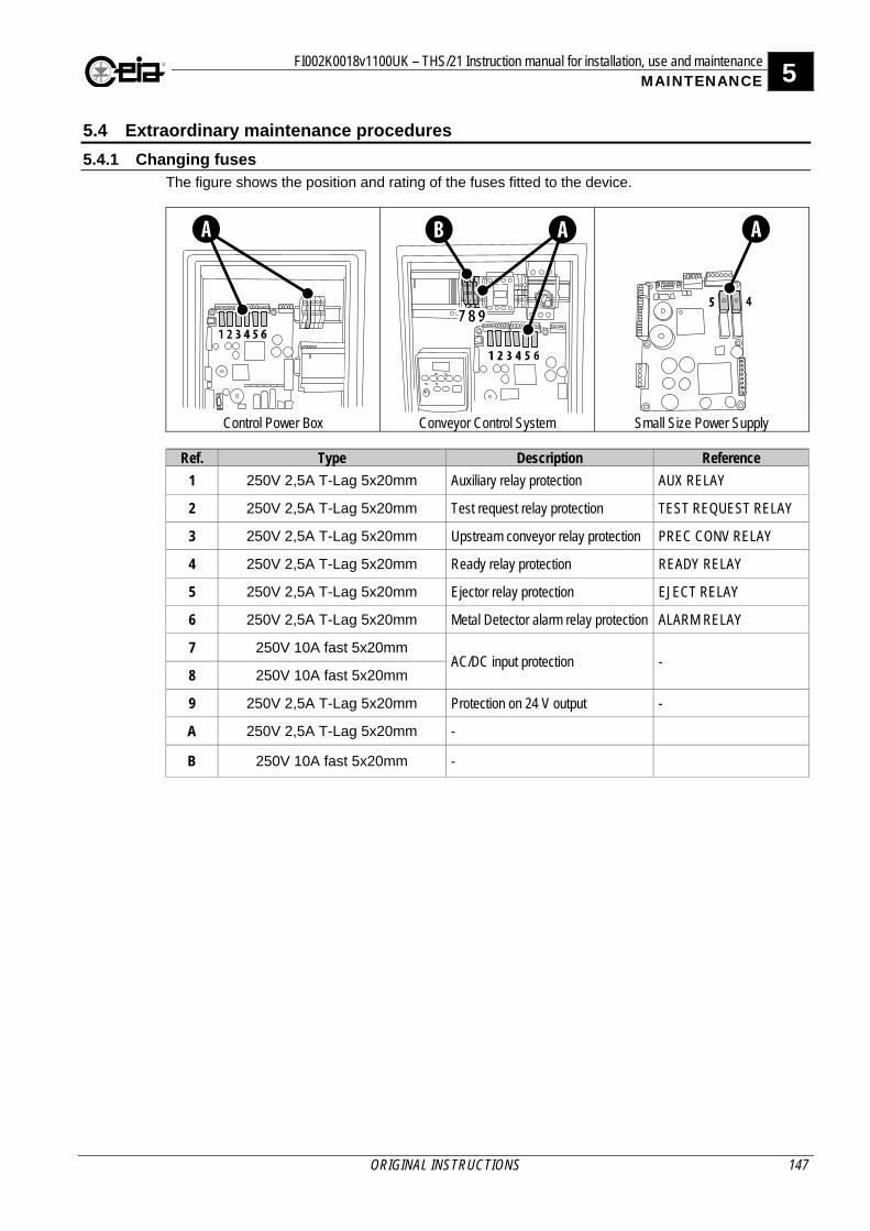
FI002K0018v1100UK – THS/21 Instruction manual for installation, use and maintenance 5 MAINTENANCE
ORIGINAL INSTRUCTIONS 147
5.4 Extraordinary maintenance procedures
5.4.1 Changing fuses The figure shows the position and rating of the fuses fitted to the device.
Control Power Box Conveyor Control System Small Size Power Supply
Ref. Type Description Reference
1 250V 2,5A T-Lag 5x20mm Auxiliary relay protection AUX RELAY
2 250V 2,5A T-Lag 5x20mm Test request relay protection TEST REQUEST RELAY
3 250V 2,5A T-Lag 5x20mm Upstream conveyor relay protection PREC CONV RELAY
4 250V 2,5A T-Lag 5x20mm Ready relay protection READY RELAY
5 250V 2,5A T-Lag 5x20mm Ejector relay protection EJECT RELAY
6 250V 2,5A T-Lag 5x20mm Metal Detector alarm relay protection ALARM RELAY
7 250V 10A fast 5x20mm AC/DC input protection -
8 250V 10A fast 5x20mm
9 250V 2,5A T-Lag 5x20mm Protection on 24 V output -
A 250V 2,5A T-Lag 5x20mm -
B 250V 10A fast 5x20mm -
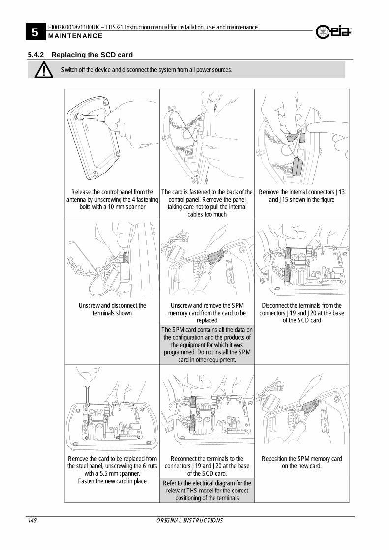
5 FI002K0018v1100UK – THS/21 Instruction manual for installation, use and maintenance MAINTENANCE
148 ORIGINAL INSTRUCTIONS
5.4.2 Replacing the SCD card
Switch off the device and disconnect the system from all power sources.
Release the control panel from the antenna by unscrewing the 4 fastening
bolts with a 10 mm spanner
The card is fastened to the back of the control panel. Remove the panel taking care not to pull the internal
cables too much
Remove the internal connectors J13 and J15 shown in the figure
Unscrew and disconnect the terminals shown
Unscrew and remove the SPM memory card from the card to be
replaced
Disconnect the terminals from the connectors J19 and J20 at the base
of the SCD card The SPM card contains all the data on the configuration and the products of
the equipment for which it was programmed. Do not install the SPM
card in other equipment.
Remove the card to be replaced from the steel panel, unscrewing the 6 nuts
with a 5.5 mm spanner. Fasten the new card in place
Reconnect the terminals to the connectors J19 and J20 at the base
of the SCD card.
Reposition the SPM memory card on the new card.
Refer to the electrical diagram for the relevant THS model for the correct
positioning of the terminals
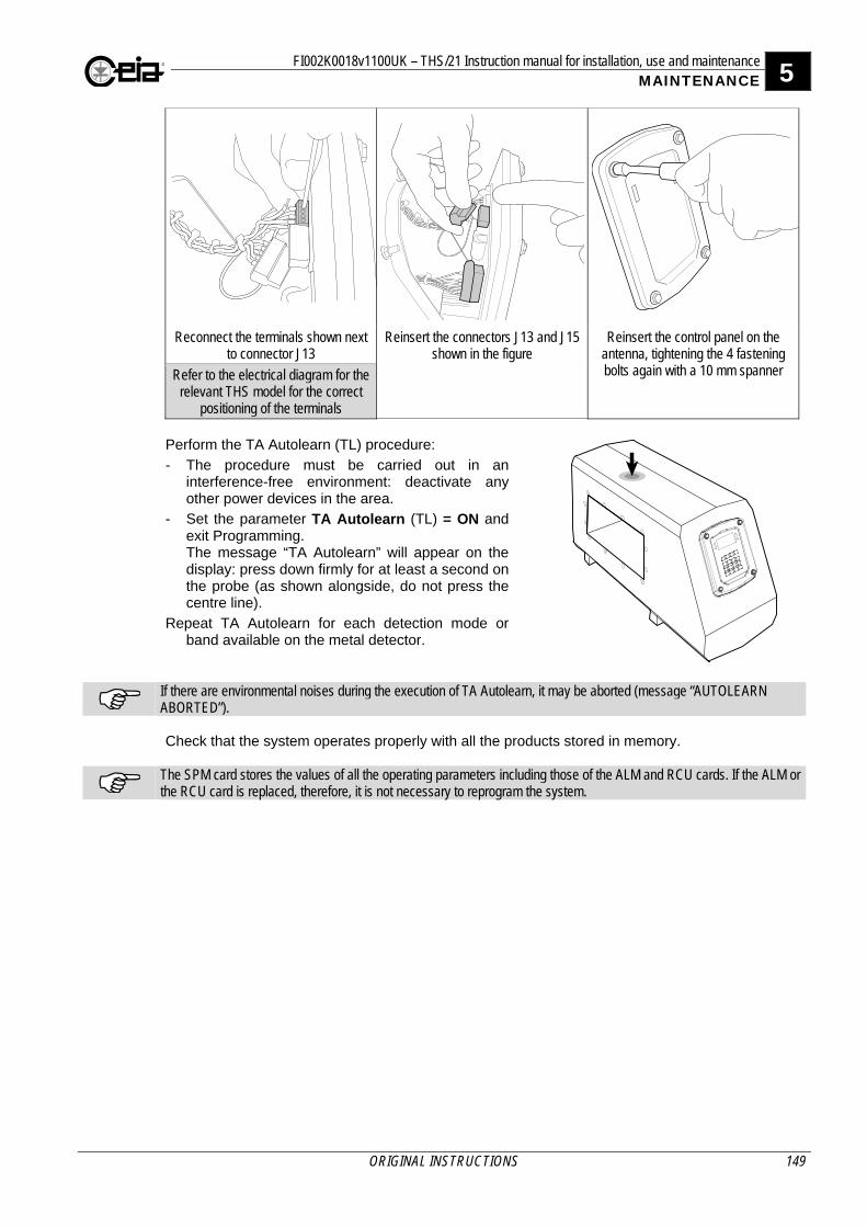
FI002K0018v1100UK – THS/21 Instruction manual for installation, use and maintenance 5 MAINTENANCE
ORIGINAL INSTRUCTIONS 149
Reconnect the terminals shown next to connector J13
Reinsert the connectors J13 and J15 shown in the figure
Reinsert the control panel on the antenna, tightening the 4 fastening bolts again with a 10 mm spanner Refer to the electrical diagram for the
relevant THS model for the correct positioning of the terminals
Perform the TA Autolearn (TL) procedure:
- The procedure must be carried out in an interference-free environment: deactivate any other power devices in the area.
- Set the parameter TA Autolearn (TL) = ON and exit Programming. The message “TA Autolearn” will appear on the display: press down firmly for at least a second on the probe (as shown alongside, do not press the centre line).
Repeat TA Autolearn for each detection mode or band available on the metal detector.
If there are environmental noises during the execution of TA Autolearn, it may be aborted (message “AUTOLEARN ABORTED”). Check that the system operates properly with all the products stored in memory.
The SPM card stores the values of all the operating parameters including those of the ALM and RCU cards. If the ALM or the RCU card is replaced, therefore, it is not necessary to reprogram the system.
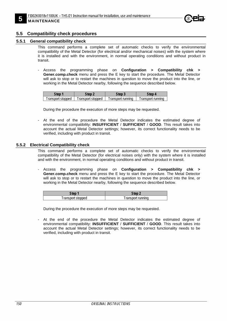
5 FI002K0018v1100UK – THS/21 Instruction manual for installation, use and maintenance MAINTENANCE
150 ORIGINAL INSTRUCTIONS
5.5 Compatibility check procedures
5.5.1 General compatibility check This command performs a complete set of automatic checks to verify the environmental compatibility of the Metal Detector (for electrical and/or mechanical noises) with the system where it is installed and with the environment, in normal operating conditions and without product in transit. - Access the programming phase on Configuration > Compatibility chk >
Gener.comp.check menu and press the E key to start the procedure. The Metal Detector will ask to stop or to restart the machines in question to move the product into the line, or working in the Metal Detector nearby, following the sequence described below.
Step 1 Step 2 Step 3 Step 4 Transport stopped Transport stopped Transport running Transport running
During the procedure the execution of more steps may be requested.
- At the end of the procedure the Metal Detector indicates the estimated degree of environmental compatibility: INSUFFICIENT / SUFFICIENT / GOOD. This result takes into account the actual Metal Detector settings; however, its correct functionality needs to be verified, including with product in transit.
5.5.2 Electrical Compatibility check This command performs a complete set of automatic checks to verify the environmental compatibility of the Metal Detector (for electrical noises only) with the system where it is installed and with the environment, in normal operating conditions and without product in transit. - Access the programming phase on Configuration > Compatibility chk >
Gener.comp.check menu and press the E key to start the procedure. The Metal Detector will ask to stop or to restart the machines in question to move the product into the line, or working in the Metal Detector nearby, following the sequence described below.
Step 1 Step 2 Transport stopped Transport running
During the procedure the execution of more steps may be requested.
- At the end of the procedure the Metal Detector indicates the estimated degree of environmental compatibility: INSUFFICIENT / SUFFICIENT / GOOD. This result takes into account the actual Metal Detector settings; however, its correct functionality needs to be verified, including with product in transit.
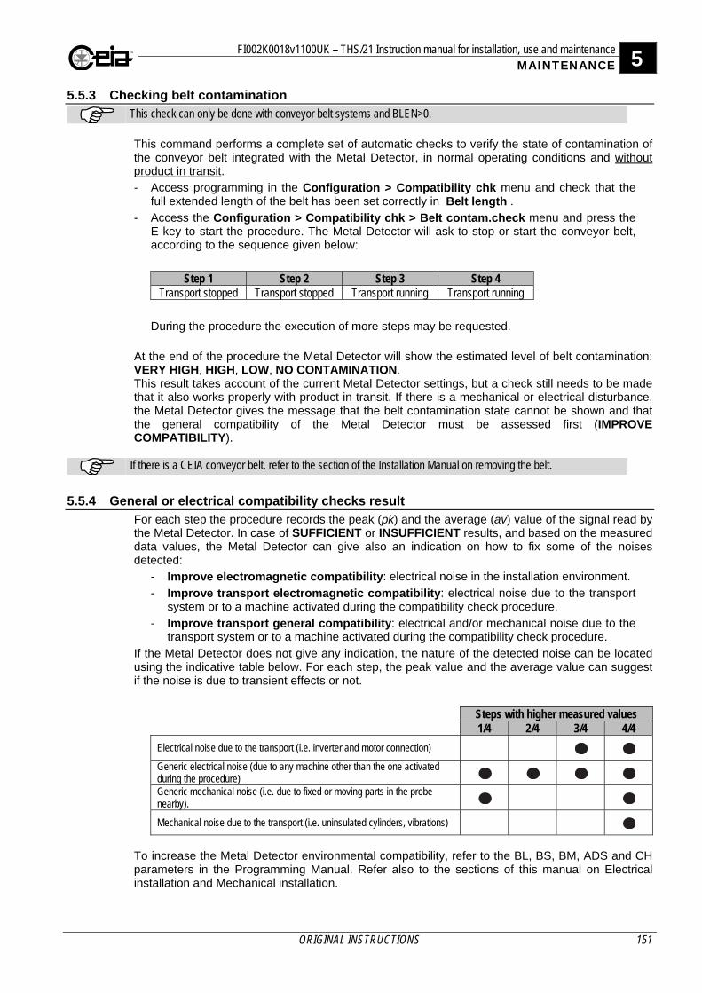
FI002K0018v1100UK – THS/21 Instruction manual for installation, use and maintenance 5 MAINTENANCE
ORIGINAL INSTRUCTIONS 151
5.5.3 Checking belt contamination
This check can only be done with conveyor belt systems and BLEN>0. This command performs a complete set of automatic checks to verify the state of contamination of the conveyor belt integrated with the Metal Detector, in normal operating conditions and without product in transit. - Access programming in the Configuration > Compatibility chk menu and check that the
full extended length of the belt has been set correctly in Belt length .
- Access the Configuration > Compatibility chk > Belt contam.check menu and press the E key to start the procedure. The Metal Detector will ask to stop or start the conveyor belt, according to the sequence given below:
Step 1 Step 2 Step 3 Step 4 Transport stopped Transport stopped Transport running Transport running
During the procedure the execution of more steps may be requested.
At the end of the procedure the Metal Detector will show the estimated level of belt contamination: VERY HIGH, HIGH, LOW, NO CONTAMINATION. This result takes account of the current Metal Detector settings, but a check still needs to be made that it also works properly with product in transit. If there is a mechanical or electrical disturbance, the Metal Detector gives the message that the belt contamination state cannot be shown and that the general compatibility of the Metal Detector must be assessed first (IMPROVE COMPATIBILITY).
If there is a CEIA conveyor belt, refer to the section of the Installation Manual on removing the belt.
5.5.4 General or electrical compatibility checks result For each step the procedure records the peak (pk) and the average (av) value of the signal read by the Metal Detector. In case of SUFFICIENT or INSUFFICIENT results, and based on the measured data values, the Metal Detector can give also an indication on how to fix some of the noises detected:
- Improve electromagnetic compatibility: electrical noise in the installation environment.
- Improve transport electromagnetic compatibility: electrical noise due to the transport system or to a machine activated during the compatibility check procedure.
- Improve transport general compatibility: electrical and/or mechanical noise due to the transport system or to a machine activated during the compatibility check procedure.
If the Metal Detector does not give any indication, the nature of the detected noise can be located using the indicative table below. For each step, the peak value and the average value can suggest if the noise is due to transient effects or not.
Steps with higher measured values 1/4 2/4 3/4 4/4
Electrical noise due to the transport (i.e. inverter and motor connection)
Generic electrical noise (due to any machine other than the one activated during the procedure)
Generic mechanical noise (i.e. due to fixed or moving parts in the probe nearby).
Mechanical noise due to the transport (i.e. uninsulated cylinders, vibrations)
To increase the Metal Detector environmental compatibility, refer to the BL, BS, BM, ADS and CH parameters in the Programming Manual. Refer also to the sections of this manual on Electrical installation and Mechanical installation.
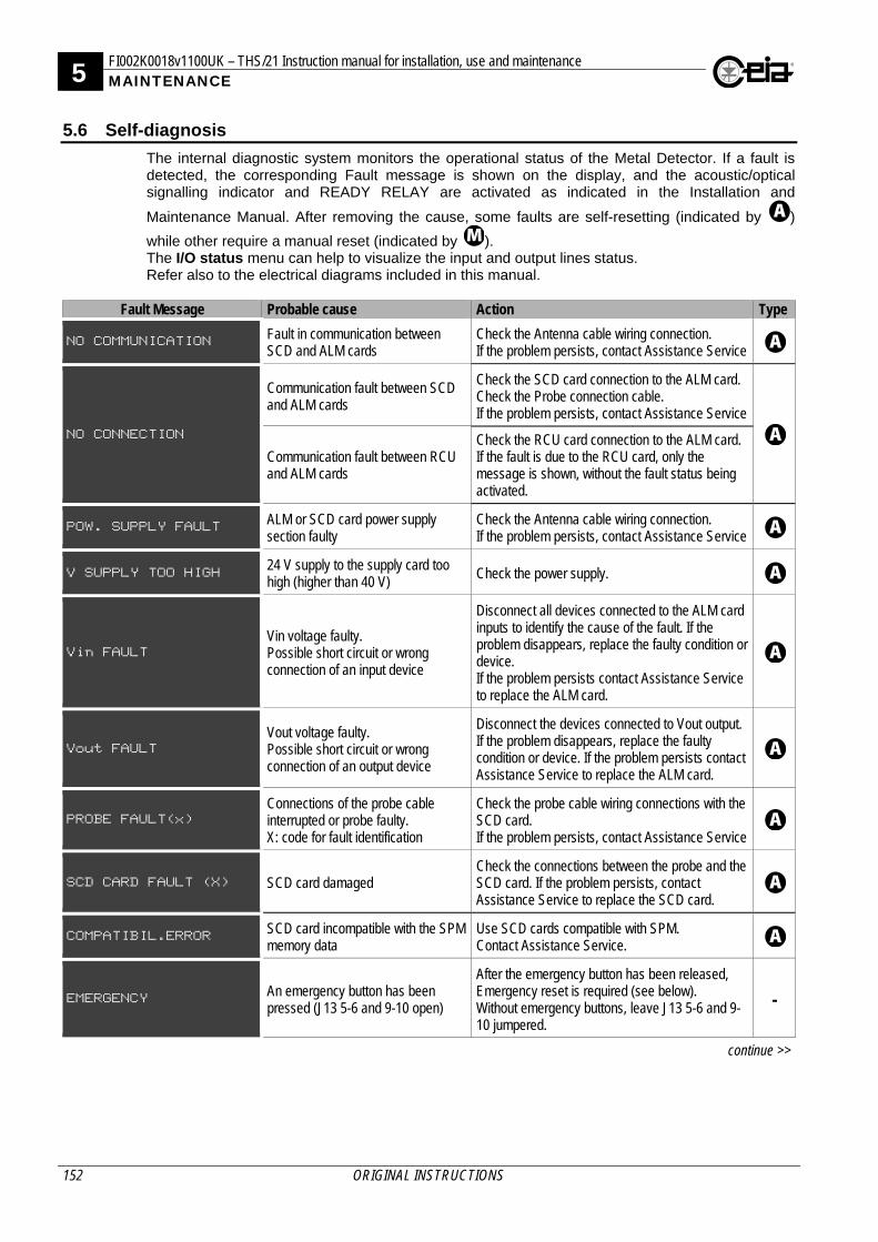
5 FI002K0018v1100UK – THS/21 Instruction manual for installation, use and maintenance MAINTENANCE
152 ORIGINAL INSTRUCTIONS
5.6 Self-diagnosis
The internal diagnostic system monitors the operational status of the Metal Detector. If a fault is detected, the corresponding Fault message is shown on the display, and the acoustic/optical signalling indicator and READY RELAY are activated as indicated in the Installation and
Maintenance Manual. After removing the cause, some faults are self-resetting (indicated by )
while other require a manual reset (indicated by ). The I/O status menu can help to visualize the input and output lines status. Refer also to the electrical diagrams included in this manual.
Fault Message Probable cause Action Type
NO COMMUNICATION Fault in communication between SCD and ALM cards
Check the Antenna cable wiring connection. If the problem persists, contact Assistance Service
NO CONNECTION
Communication fault between SCD and ALM cards
Check the SCD card connection to the ALM card. Check the Probe connection cable. If the problem persists, contact Assistance Service
Communication fault between RCU and ALM cards
Check the RCU card connection to the ALM card. If the fault is due to the RCU card, only the message is shown, without the fault status being activated.
POW. SUPPLY FAULT ALM or SCD card power supply section faulty
Check the Antenna cable wiring connection. If the problem persists, contact Assistance Service
V SUPPLY TOO HIGH 24 V supply to the supply card too high (higher than 40 V)
Check the power supply.
Vin FAULT
Vin voltage faulty. Possible short circuit or wrong connection of an input device
Disconnect all devices connected to the ALM card inputs to identify the cause of the fault. If the problem disappears, replace the faulty condition or device. If the problem persists contact Assistance Service to replace the ALM card.
Vout FAULT
Vout voltage faulty. Possible short circuit or wrong connection of an output device
Disconnect the devices connected to Vout output. If the problem disappears, replace the faulty condition or device. If the problem persists contact Assistance Service to replace the ALM card.
PROBE FAULT(x)
Connections of the probe cable interrupted or probe faulty. X: code for fault identification
Check the probe cable wiring connections with the SCD card. If the problem persists, contact Assistance Service
SCD CARD FAULT (X) SCD card damaged Check the connections between the probe and the SCD card. If the problem persists, contact Assistance Service to replace the SCD card.
COMPATIBIL.ERROR SCD card incompatible with the SPM memory data
Use SCD cards compatible with SPM. Contact Assistance Service.
EMERGENCY An emergency button has been pressed (J13 5-6 and 9-10 open)
After the emergency button has been released, Emergency reset is required (see below). Without emergency buttons, leave J13 5-6 and 9-10 jumpered.
-
continue >>
FI002K0018v1100UK – THS/21 Instruction manual for installation, use and maintenance 5 MAINTENANCE
ORIGINAL INSTRUCTIONS 153
Fault Message Probable cause Action Type
RESET EMERGENCY
A manual reset is required after the emergency button has been released or when starting the Conveyor Control System
Press R to enable the conveyor belt and the ejector. Without emergency buttons, leave J5 4-5 jumpered.
EXTERN EMERGENCY The external emergency button has been pressed (J13 3-4 open)
After the emergency button has been released, Emergency reset is required (see above). Without emergency buttons, leave J13 3-4 jumpered.
-
EMERG.CIRC.FAULT Emergency circuit faulty. ((J13 5-6 or 9-10 open)
Check the Emergency button connections. After removing the cause, press the Emergency Reset button to reset the Fault status. If the problem persists, contact Assistance Service.
-
BIN FULL
Reject bin full Empty the bin.
Sensor connected to the BIN FULL input faulty or disconnected
Check the sensor mechanical and electrical installation. Check the correct programming, simulating the input activation and verify (in I/O Status menu) that the status changes correctly. If the problem persists, contact Assistance Service.
BIN ABSENT
Reject bin absent or not correctly in position
Put the bin back in the correct position.
Sensor connected to the BIN ABSENT input faulty or disconnected
Check the sensor mechanical and electrical installation. Check the correct programming, simulating the input activation and verify (in I/O Status menu) that the status changes correctly. If the problem persists, contact Assistance Service.
LOW AIR PRESSURE
Air supply pressure too low Check the air supply connection and pressure.
Sensor connected to the LOW PRESSURE input faulty or disconnected
Check the sensor electrical installation. Check the correct programming, simulating the input activation and verify (in I/O Status menu) that the status changes correctly. If the problem persists, contact Assistance Service.
NO EJECT.CONFIRM
Product ejection not correctly confirmed
Check that the ejector is correctly activated and that the product is properly ejected.
Self-diagnosis not correctly set Check that the ejection confirmation diagnosis is
correctly programmed for the application.
Sensor connected to the EJ.CONFIRMATION input faulty or disconnected
Check the sensor mechanical and electrical connections. If the problem persists, contact Assistance Service.
continue >>
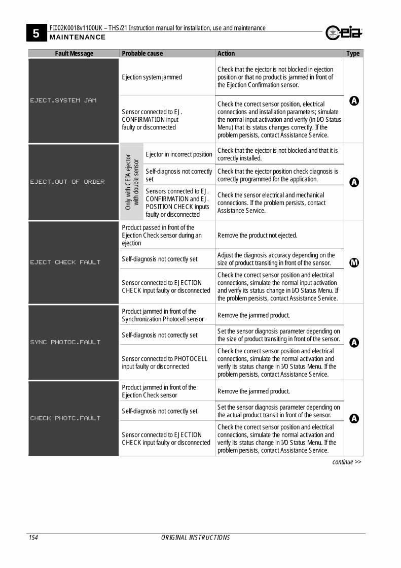
5 FI002K0018v1100UK – THS/21 Instruction manual for installation, use and maintenance MAINTENANCE
154 ORIGINAL INSTRUCTIONS
Fault Message Probable cause Action Type
EJECT.SYSTEM JAM
Ejection system jammed Check that the ejector is not blocked in ejection position or that no product is jammed in front of the Ejection Confirmation sensor.
Sensor connected to EJ. CONFIRMATION input faulty or disconnected
Check the correct sensor position, electrical connections and installation parameters; simulate the normal input activation and verify (in I/O Status Menu) that its status changes correctly. If the problem persists, contact Assistance Service.
EJECT.OUT OF ORDER
Onl
y w
ith C
EIA
ejec
tor
with
dou
ble
sens
or Ejector in incorrect position Check that the ejector is not blocked and that it is
correctly installed.
Self-diagnosis not correctly set
Check that the ejector position check diagnosis is correctly programmed for the application.
Sensors connected to EJ. CONFIRMATION and EJ. POSITION CHECK inputs faulty or disconnected
Check the sensor electrical and mechanical connections. If the problem persists, contact Assistance Service.
EJECT CHECK FAULT
Product passed in front of the Ejection Check sensor during an ejection
Remove the product not ejected.
Self-diagnosis not correctly set Adjust the diagnosis accuracy depending on the size of product transiting in front of the sensor.
Sensor connected to EJECTION CHECK input faulty or disconnected
Check the correct sensor position and electrical connections, simulate the normal input activation and verify its status change in I/O Status Menu. If the problem persists, contact Assistance Service.
SYNC PHOTOC.FAULT
Product jammed in front of the Synchronization Photocell sensor Remove the jammed product.
Self-diagnosis not correctly set
Set the sensor diagnosis parameter depending on the size of product transiting in front of the sensor.
Sensor connected to PHOTOCELL input faulty or disconnected
Check the correct sensor position and electrical connections, simulate the normal activation and verify its status change in I/O Status Menu. If the problem persists, contact Assistance Service.
CHECK PHOTC.FAULT
Product jammed in front of the Ejection Check sensor
Remove the jammed product.
Self-diagnosis not correctly set
Set the sensor diagnosis parameter depending on the actual product transit in front of the sensor.
Sensor connected to EJECTION CHECK input faulty or disconnected
Check the correct sensor position and electrical connections, simulate the normal activation and verify its status change in I/O Status Menu. If the problem persists, contact Assistance Service.
continue >>
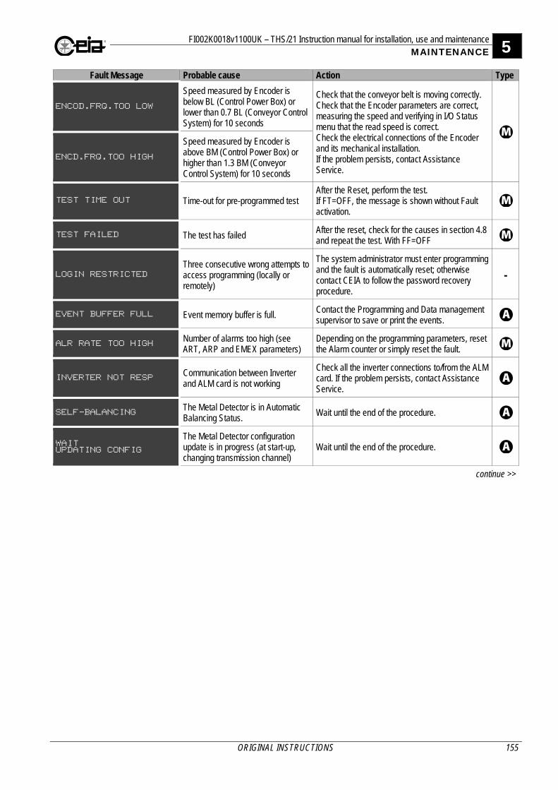
FI002K0018v1100UK – THS/21 Instruction manual for installation, use and maintenance 5 MAINTENANCE
ORIGINAL INSTRUCTIONS 155
Fault Message Probable cause Action Type
ENCOD.FRQ.TOO LOW
Speed measured by Encoder is below BL (Control Power Box) or lower than 0.7 BL (Conveyor Control System) for 10 seconds
Check that the conveyor belt is moving correctly. Check that the Encoder parameters are correct, measuring the speed and verifying in I/O Status menu that the read speed is correct. Check the electrical connections of the Encoder and its mechanical installation. If the problem persists, contact Assistance Service.
ENCD.FRQ.TOO HIGH
Speed measured by Encoder is above BM (Control Power Box) or higher than 1.3 BM (Conveyor Control System) for 10 seconds
TEST TIME OUT Time-out for pre-programmed test After the Reset, perform the test. If FT=OFF, the message is shown without Fault activation.
TEST FAILED The test has failed After the reset, check for the causes in section 4.8 and repeat the test. With FF=OFF
LOGIN RESTRICTED
Three consecutive wrong attempts to access programming (locally or remotely)
The system administrator must enter programming and the fault is automatically reset; otherwise contact CEIA to follow the password recovery procedure.
-
EVENT BUFFER FULL Event memory buffer is full. Contact the Programming and Data management supervisor to save or print the events.
ALR RATE TOO HIGH Number of alarms too high (see ART, ARP and EMEX parameters)
Depending on the programming parameters, reset the Alarm counter or simply reset the fault.
INVERTER NOT RESP Communication between Inverter and ALM card is not working
Check all the inverter connections to/from the ALM card. If the problem persists, contact Assistance Service.
SELF-BALANCING The Metal Detector is in Automatic Balancing Status.
Wait until the end of the procedure.
WAIT UPDATING CONFIG
The Metal Detector configuration update is in progress (at start-up, changing transmission channel)
Wait until the end of the procedure.
continue >>
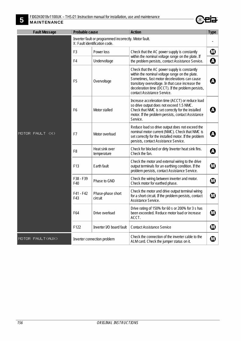
5 FI002K0018v1100UK – THS/21 Instruction manual for installation, use and maintenance MAINTENANCE
156 ORIGINAL INSTRUCTIONS
Fault Message Probable cause Action Type
MOTOR FAULT (X)
Inverter fault or programmed incorrectly. Motor fault. X: Fault identification code. -
F3 Power loss Check that the AC power supply is constantly within the nominal voltage range on the plate. If the problem persists, contact Assistance Service.
F4 Undervoltage
F5 Overvoltage
Check that the AC power supply is constantly within the nominal voltage range on the plate. Sometimes, fast motor decelerations can cause transitory overvoltage. In that case increase the deceleration time (DCCT). If the problem persists, contact Assistance Service.
F6 Motor stalled
Increase acceleration time (ACCT) or reduce load so drive output does not exceed 1.5 NMC. Check that NMC is set correctly for the installed motor. If the problem persists, contact Assistance Service.
F7 Motor overload
Reduce load so drive output does not exceed the nominal motor current (NMC). Check that NMC is set correctly for the installed motor. If the problem persists, contact Assistance Service.
F8 Heat sink over temperature
Check for blocked or dirty Inverter heat sink fins. Check the fan.
F13 Earth fault Check the motor and external wiring to the drive output terminals for an earthing condition. If the problem persists, contact Assistance Service.
F38 - F39 F40
Phase to GND Check the wiring between inverter and motor. Check motor for earthed phase.
F41 - F42 F43
Phase-phase short circuit
Check the motor and drive output terminal wiring for a short circuit. If the problem persists, contact Assistance Service.
F64 Drive overload Drive rating of 150% for 60 s or 200% for 3 s has been exceeded. Reduce motor load or increase ACCT.
F122 Inverter I/O board fault Contact Assistance Service
MOTOR FAULT(AUX) Inverter connection problem Check the connection of the inverter cable to the ALM card. Check the jumper status on it.
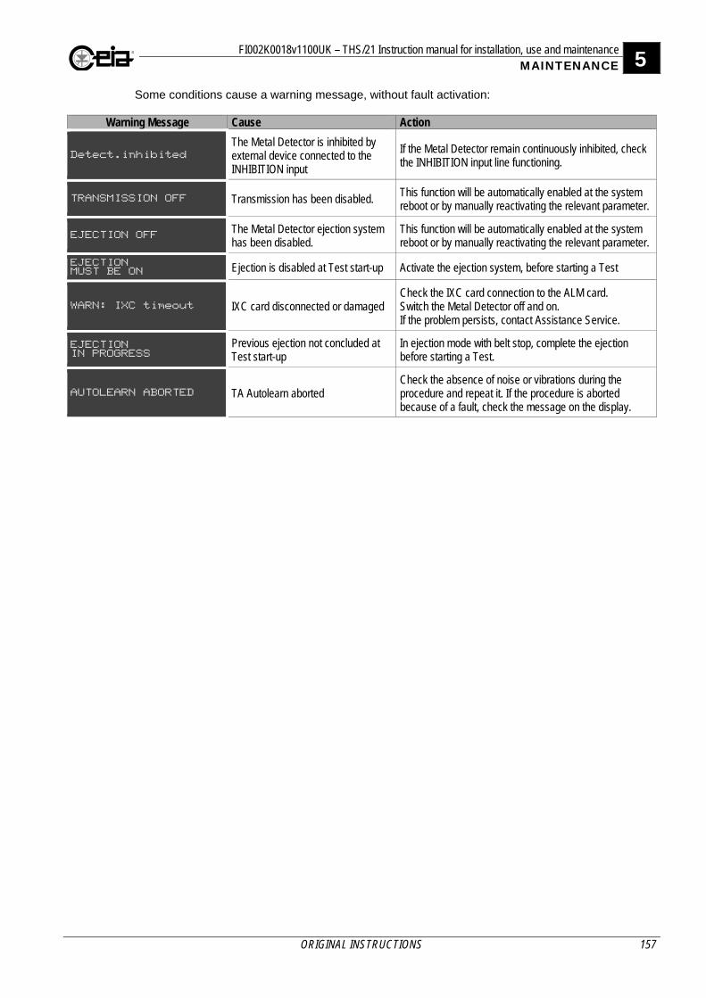
FI002K0018v1100UK – THS/21 Instruction manual for installation, use and maintenance 5 MAINTENANCE
ORIGINAL INSTRUCTIONS 157
Some conditions cause a warning message, without fault activation:
Warning Message Cause Action
Detect.inhibited
The Metal Detector is inhibited by external device connected to the INHIBITION input
If the Metal Detector remain continuously inhibited, check the INHIBITION input line functioning.
TRANSMISSION OFF Transmission has been disabled. This function will be automatically enabled at the system reboot or by manually reactivating the relevant parameter.
EJECTION OFF The Metal Detector ejection system has been disabled.
This function will be automatically enabled at the system reboot or by manually reactivating the relevant parameter.
EJECTION MUST BE ON Ejection is disabled at Test start-up Activate the ejection system, before starting a Test
WARN: IXC timeout IXC card disconnected or damaged Check the IXC card connection to the ALM card. Switch the Metal Detector off and on. If the problem persists, contact Assistance Service.
EJECTION IN PROGRESS
Previous ejection not concluded at Test start-up
In ejection mode with belt stop, complete the ejection before starting a Test.
AUTOLEARN ABORTED TA Autolearn aborted Check the absence of noise or vibrations during the procedure and repeat it. If the procedure is aborted because of a fault, check the message on the display.
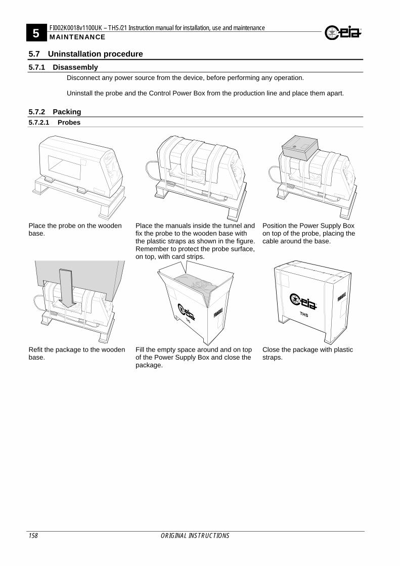
5 FI002K0018v1100UK – THS/21 Instruction manual for installation, use and maintenance MAINTENANCE
158 ORIGINAL INSTRUCTIONS
5.7 Uninstallation procedure
5.7.1 Disassembly Disconnect any power source from the device, before performing any operation. Uninstall the probe and the Control Power Box from the production line and place them apart.
5.7.2 Packing
5.7.2.1 Probes
Place the probe on the wooden base.
Place the manuals inside the tunnel and fix the probe to the wooden base with the plastic straps as shown in the figure. Remember to protect the probe surface, on top, with card strips.
Position the Power Supply Box on top of the probe, placing the cable around the base.
Refit the package to the wooden base.
Fill the empty space around and on top of the Power Supply Box and close the package.
Close the package with plastic straps.
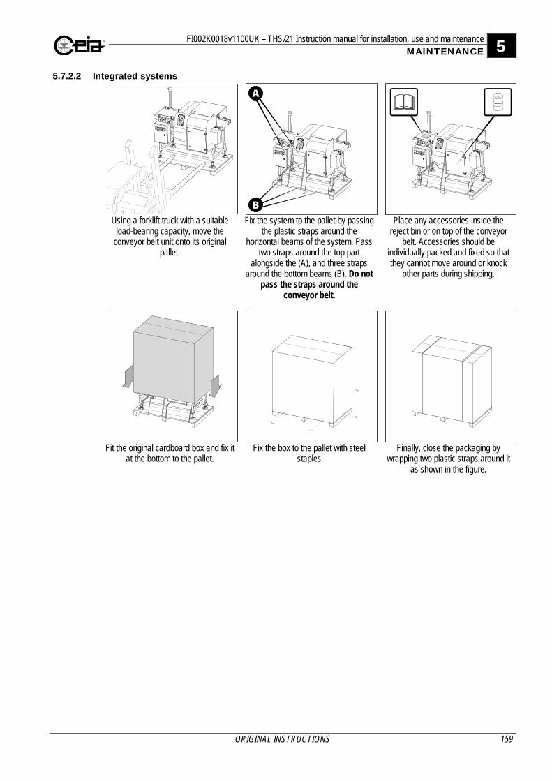
FI002K0018v1100UK – THS/21 Instruction manual for installation, use and maintenance 5 MAINTENANCE
ORIGINAL INSTRUCTIONS 159
5.7.2.2 Integrated systems
Using a forklift truck with a suitable load-bearing capacity, move the
conveyor belt unit onto its original pallet.
Fix the system to the pallet by passing the plastic straps around the
horizontal beams of the system. Pass two straps around the top part
alongside the (A), and three straps around the bottom beams (B). Do not
pass the straps around the conveyor belt.
Place any accessories inside the reject bin or on top of the conveyor
belt. Accessories should be individually packed and fixed so that they cannot move around or knock
other parts during shipping.
Fit the original cardboard box and fix it at the bottom to the pallet.
Fix the box to the pallet with steel staples
Finally, close the packaging by wrapping two plastic straps around it
as shown in the figure.
A
B

5 FI002K0018v1100UK – THS/21 Instruction manual for installation, use and maintenance MAINTENANCE
160 ORIGINAL INSTRUCTIONS
5.8 Disposal of the device
5.8.1 Disposal of the device and of consumables with environmental impact For disposal follow the regulations in force in the country where the device is being used.
FI002K0018v1100UK – THS/21 Instruction manual for installation, use and maintenance 6 APPENDICES
ORIGINAL INSTRUCTIONS 161
6 APPENDICES 6.1 CE Declaration of Conformity
6.1.1 THS/21, THS/G21, THS/SL21, THSMN21, THS/MS21

6 FI 023 I 2K8 v3 – THS/G-ATEX Instruction manual APPENDICES
162 ORIGINAL INSTRUCTIONS
6.1.2 THS/FB, THS/FBB, THS/M69K, THS/MBB and THS/MBR Originals of the CE Declaration of Conformity for each model are provided with the documentation.
6.2 Spare Parts
For the list of spare parts available for each model, see the Spare parts, Accessories and Options Manual.


![[doi 10.1007%2F978-1-4020-2103-9_6] Shur, Michael S.; Žukauskas, Artūras -- UV Solid-State Light Emitters and Detectors __ UV Metal Semiconductor Metal Detectors (1).pdf](https://img.pdfslide.us/doc/110x75/577c7d3a1a28abe0549de5a7/doi-1010072f978-1-4020-2103-96-shur-michael-s-zukauskas-arturas.jpg)