Embed Size (px)
Citation preview

1
E l e c t r a kM o v o a c t
L o a d M a s t e r 8 0A c t u a t o r C o n t r o l s
. GB
www.LinearActuators.com
Industrial LinearActuators
2
Conventions• Drawings are made to European standard.
• Comma (,) instead of a point (.) is used as separator between
integers and decimals (e.g. 40,5).
• All dimensions are metric unless otherwise stated. For conversion
to imperial measures, please use the chart below.
To obtain Multiply By
inches mm 0,0393701
feet mm 0,00328084
inches m 39,3701
feet m 3,28084
lb. -force N 0,224809
lb ft Nm 0,737562
lb kg 2,20462
feet/sec m/s 3,28084
DANAHER MOTION is a trademark.
Danaher Motion makes every attempt to ensure accuracy and reliability
of the specifi cations in this publication. Specifi cations are subject to
change without notice. Danaher Motion provides this information “AS
IS” and disclaims all warranties, express or implied, including, but not
limited to, implied warranties of merchantability and fi tness for a particu-
lar purpose. It is the responsibility of the product user to determine the
suitability of this product for a specifi c application.
© February, 2004 Danaher Motion
1 2 3 4 5 6 7 8 9 10 11 12 13 14 15 16 17 18 19 200
3
Introduction
Rugged and reliableThomson Tollo linear actuators incorporate strong, high
quality components that has been proven under the hard-
est operation conditions to ensure a long and trouble free
operation.
Rugged spur gearings, aircraft quality lubricants, non
corrosive extension tube and high performance motors
with built in thermal protection maximum the life and value
for the user.
Linear actuator advantagesA Thomson Tollo actuator with 100 mm stroke can pro-
vide 6800 N of force from a 300 mm long package. This
means that pneumatic and hyudralic cylinders easily can
be replaced thus saving energy, space and power sourc-
es while making control easier and accurate positioning
possible.
The actuators will operate equally well if pulling or push-
ing the load. They hold a load indefi nitely without power
and can be equipped with position feedback devices, limit
switches and other optional functions and features.
Broad range of modelsThe broad range of models makes it easy to choose the
perfect actuator for your application. We can offer an
actuator whether it should be small, fast, quiet, strong,
wheater protected or light weight. And if you can not fi nd
anything that fi ts among our standard range we are happy
to customize an actuator to your needs.
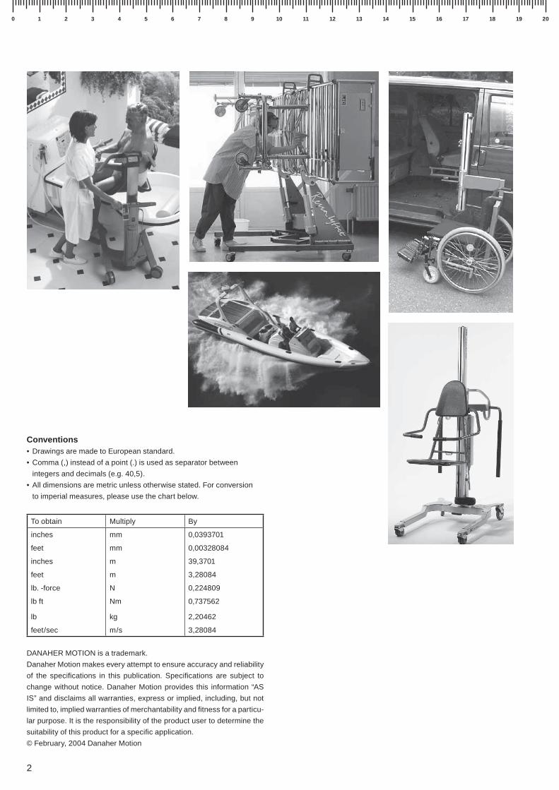
Typical applicationsApplications areas where linear actuators are used in-
cludes:
• Mobile-off-Highway equipment (harvesters, tractors,
trucks, bailers, forestry vehicles, trains, construction
equipment, boats, etc.)
• Health and fi tness equipment (x-ray equipment, wheel
chairs, handicap adaption of cars, gym equipment,
dental chairs, patient lifts, etc.)
• In ventilation and valve control
• In the operation of windows, gates, doors and hatches
• In all type of industrial equipment where linear motion is
a need.

4
Performance overview
Actuator
model
Max.
load
[N]
Max.
stroke
[mm]
Max.
speed
[mm/s]
Available
supply voltages
Available
screw types
Overload
clutch
End of stroke
limit switches
Anti rotation
mechanism
[Vdc] [Vac] Acme Ball Worm Yes No Yes No Yes No
Electrak LA1-S 500 150 75 12, 24, 36 x x x x
Electrak LA1-SP 500 150 75 12, 24, 36 x x x x
Electrak LA10 6800 600 60 12, 24, 36 x x x x x
Electrak LA14 6800 600 60 12, 24, 36 x x x x x
Electrak LA5 6800 600 60 230, 400 x x x x x
Electrak LA24 6800 600 60 230, 400 x x x x x
Electrak FA14 6800 600 60 no motor no motor x x x x x
Electrak PPA-AC 6670 914 33 110, 230 x x x* x
Electrak PPA-DC 6670 914 15 12, 24, 36 x x x* x
Electrak PPA-M 6670 914 8,3 no motor no motor x x x x
Electrak E050 510 200 48 12, 24, 36 x x x* x
Electrak Q050 510 200 38 12, 24, 36 x x x* x
Electrak E150 2000 400 71 12, 24, 36 x x x* x
Movoact-AC 6800 600 60 230, 400 x x x x x
Movoact-DC 6800 600 60 12, 24, 36 x x x x x
LoadMaster 80 2000 1500 110 12, 24 x x x x not applicable
Control
model
Part numberSuitable
actuators
Input voltage Output
voltage
[Vdc]
Number
of
outputs
Max. output
current
[A]
Duty cycle
@ 20° C
[%]
Electronic
limit
switches
Limit
switch
inputs[Vac] [Vdc]
AC-020 DCB21-1S3 LA1 230 – 24 1 3 10 yes no
AC-020 DCB24-2S33 LA1 230 – 24 2 3 10 yes no
AC-050 DCE24-1E E050, Q050 230 – 24 1 2,5 10 yes no
AC-050 DCE24-2E E050, Q050 230 – 24 2 2,5 10 yes no
AC-150 DCE24-1F E150, LoadMaster 80 230 – 24 1 8 10 yes no
AC-150 DCE24-2F E150, LoadMaster 80 230 – 24 2 8 10 yes no
AC-063B DCA24-1B LA14 – 12 – 36 12 – 36 1 30 – 12 10 no yes
AC-063B DC24-1B LA10, PPA-DC, Movoact – 12 – 36 12 – 36 1 30 – 12 10 no no
AC-063C DCA24-1C LA14 230 – 24 1 17 10 no yes
AC-063C DC24-1C LA10, PPA-DC, Movoact 230 – 24 1 17 10 no no
AC-247ELS D604 110LA1, E050, Q050,
E150, LoadMaster 80– 12 – 24 12 – 24 1 10 – 5 10 yes no
AC-247ELS D604 111LA1, E050, Q050,
E150, LoadMaster 80– 12 12 1 12 10 yes no
AC-247ELS D604 112LA1, E050, Q050,
E150, LoadMaster 80– 24 24 1 8 10 yes no
Actuators
Controls
* optional
5
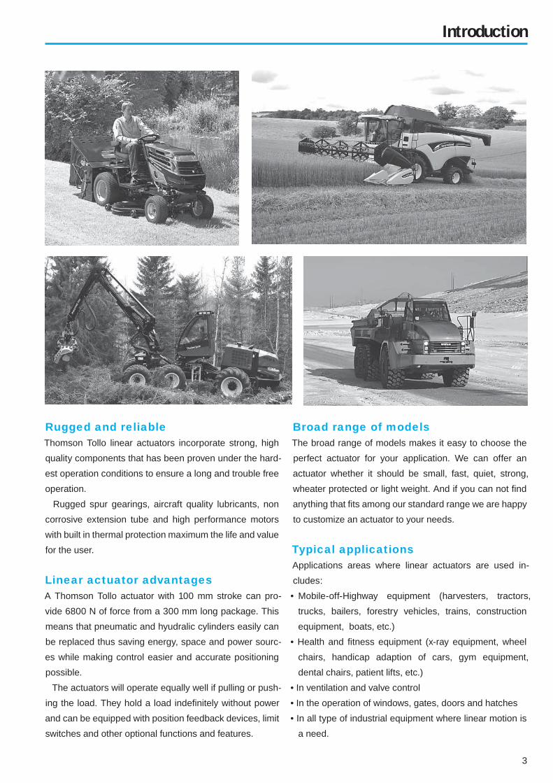
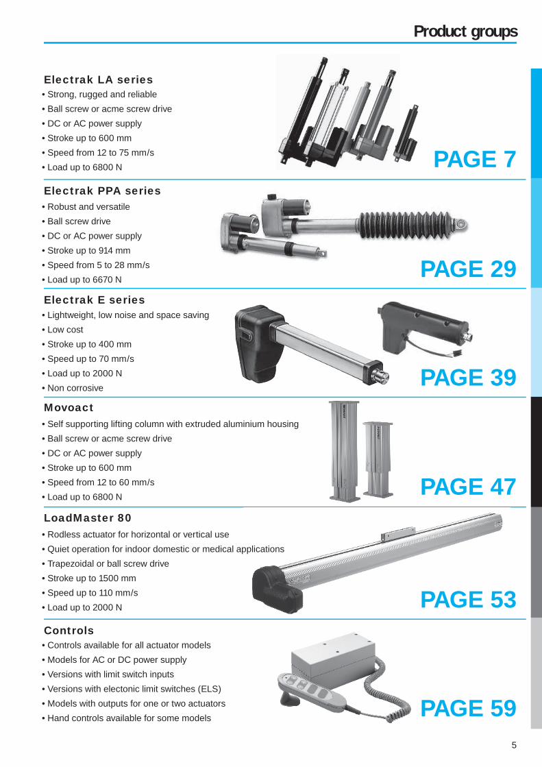
Product groups
• Strong, rugged and reliable
• Ball screw or acme screw drive
• DC or AC power supply
• Stroke up to 600 mm
• Speed from 12 to 75 mm/s
• Load up to 6800 N
LoadMaster 80
Electrak LA series
Electrak E series
Movoact
• Robust and versatile
• Ball screw drive
• DC or AC power supply
• Stroke up to 914 mm
• Speed from 5 to 28 mm/s
• Load up to 6670 N
• Lightweight, low noise and space saving
• Low cost
• Stroke up to 400 mm
• Speed up to 70 mm/s
• Load up to 2000 N
• Non corrosive
PAGE 7
PAGE 29
PAGE 39
PAGE 47
PAGE 59
Electrak PPA series
PAGE 53
• Self supporting lifting column with extruded aluminium housing
• Ball screw or acme screw drive
• DC or AC power supply
• Stroke up to 600 mm
• Speed from 12 to 60 mm/s
• Load up to 6800 N
• Rodless actuator for horizontal or vertical use
• Quiet operation for indoor domestic or medical applications
• Trapezoidal or ball screw drive
• Stroke up to 1500 mm
• Speed up to 110 mm/s
• Load up to 2000 N
• Controls available for all actuator models
• Models for AC or DC power supply
• Versions with limit switch inputs
• Versions with electonic limit switches (ELS)
• Models with outputs for one or two actuators
• Hand controls available for some models
Controls

6
Technology overview
Basic actuator design
Technology overview
Anti coast brakeBall screw actuators with an AC motor can, depending of the load, overrun before it comes
to a complete stand still after the power is being switched off. This overrun is eliminated
by the anti coast brake option.
Anti rotation mechanismThe anti rotation mechanism prevents the extension tube from rotating at the end of stroke
thus eliminating the restraining torque.
Duty cycleThe duty cycle is the allowed time in percent of the total time that he actuator may be work-
ing at the maximum rated load at a specifi ed temperature. Example: a duty cycle of 25 % at
25° C means that a unit that runs for 10 second must be off for 30 seconds (10 / (10+30) =
25 %) if the temperature is 25° C and it runs at max. rated load. The duty cycle may be higher
if the temperature is lower or/and the load is less than maximum.
ELS - Electronic Limit SwitchesELS which stands for Electronic Limit Switches and is a current sensing function used in
some actuator control models. The function sense the current and if the current exceeds
a pre-set level in any direction the control cuts the power to the motor in that particular
direction. This function can be used to detect and stop at the ends of the actuator stroke
or to stop the actuator if it runs into an obstacle.
IP codeThe IP code describe how well the actuator is protected from objects and water.
IP33: protected against the penetration of solid objects having a diameter greater than 2,5
mm and from rain at an angle up to 60°.
IP44: protected against the penetration of solid objects having a diameter greater than 1
mm and from splashing water in all directions.
IP45: protected against the penetration of solid objects having a diameter greater than 1
mm and from water jets in all directions.
IP51: protected from dust and vertical dripping water (condensation).
IP56: protected from dust and jets of water and waves in all directions.
IP65: dust tight and protected against water jets in all directions.
Limit switchesThere are two types of limit switches. The "end of stroke limit switches" stops the motion
at the end of the stroke while the "adjustable limit switches" can be set to stop the motion
at any desired position along the stroke.
Maximum operation timeThe maximum operation time is the max. time that the actuator may work before it must stand
still with the power switched off. If the duty cycle is 25 % and the max. operation time is 45
seconds then the actuator may run for 45 seconds before it must stand still for 180 seconds.
Position feedback optionThe position feedback can either be obtained by a potentiometer or a hall effect sensor. In
the fi rst case a potentiometer in the actuator linearly changes resistance in accordance
with the position of the extension tube. In the second case a hall effect sensor generates
a pulse every 0,84 mm of extension tube travel. In both cases the restistance/pulses are
measured/counted by a customer supplied control.
Restraining torqueRestraining torque is the torque that the load and the holding brackets must withstand so
that the extension tube moves instead of rotate. Actuators with "anti rotation mechanism"
do not have any restraining torque as they are restrained internally.
Spline safety functionThe spline safety function is an optional safety function on LoadMaster 80 that will stop
downwards motion in case the carriage (the moving member) collides with an obstacle.
The motor will keep running but the carriage will stand still. When reversing the motor
rotation the carriage will automatically start to move upwards again.
7
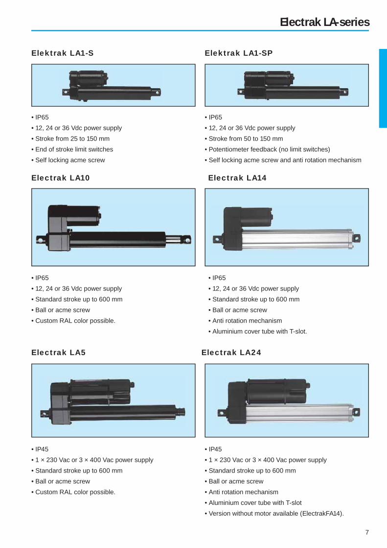
Electrak LA-series
Elektrak LA1-S
Electrak LA10 Electrak LA14
Electrak LA5 Electrak LA24
• IP45
• 1 × 230 Vac or 3 × 400 Vac power supply
• Standard stroke up to 600 mm
• Ball or acme screw
• Anti rotation mechanism
• Aluminium cover tube with T-slot
• Version without motor available (ElectrakFA14).
• IP65
• 12, 24 or 36 Vdc power supply
• Stroke from 25 to 150 mm
• End of stroke limit switches
• Self locking acme screw
• IP65
• 12, 24 or 36 Vdc power supply
• Stroke from 50 to 150 mm
• Potentiometer feedback (no limit switches)
• Self locking acme screw and anti rotation mechanism
• IP65
• 12, 24 or 36 Vdc power supply
• Standard stroke up to 600 mm
• Ball or acme screw
• Anti rotation mechanism
• Aluminium cover tube with T-slot.
• IP65
• 12, 24 or 36 Vdc power supply
• Standard stroke up to 600 mm
• Ball or acme screw
• Custom RAL color possible.
• IP45
• 1 × 230 Vac or 3 × 400 Vac power supply
• Standard stroke up to 600 mm
• Ball or acme screw
• Custom RAL color possible.
Elektrak LA1-SP

8
Electrak LA1 -S and LA1-SP
Available input voltages [Vdc] 12, 24 or 36
Available screw types Acme
Max. static load at fully retracted [N] 1300
Min. / max. standard stroke [inch]
S-model
SP-model
1 / 6
2 / 6
Duty cycle @ 25° C [%] 25
Temperature limits at operation [°C] - 25 to + 65
Protection degree IP65
Max. end play [mm] 0,9
Restraining torque [Nm]
S-model
SP-model
2,3
–
Wire cross section [mm2] 1
Wire length [mm] 100
Connector included yes
Technical data Features for both LA1-S and LA1-SP
• Small
• Weather resistant (IP65)
• Withstand 96 hour salt spray test
• Motor with auto reset thermal overload protection
• Self locking acme screw
• Can operate in a large temperature range
• Accepts large input voltage variations
• Maintenance free
• Models with higher load capacity possible on demand
• End of stroke limit switches
• Six standard strokes
• Potentiometer feedback
• Anti rotation mechanism
• Three standard strokes
• Custom RAL color
• No clutch
ModelMax.
dynamic
load [N]
Speed
@ min. load
[mm/s]
Speed
@ max. load
[mm/s]
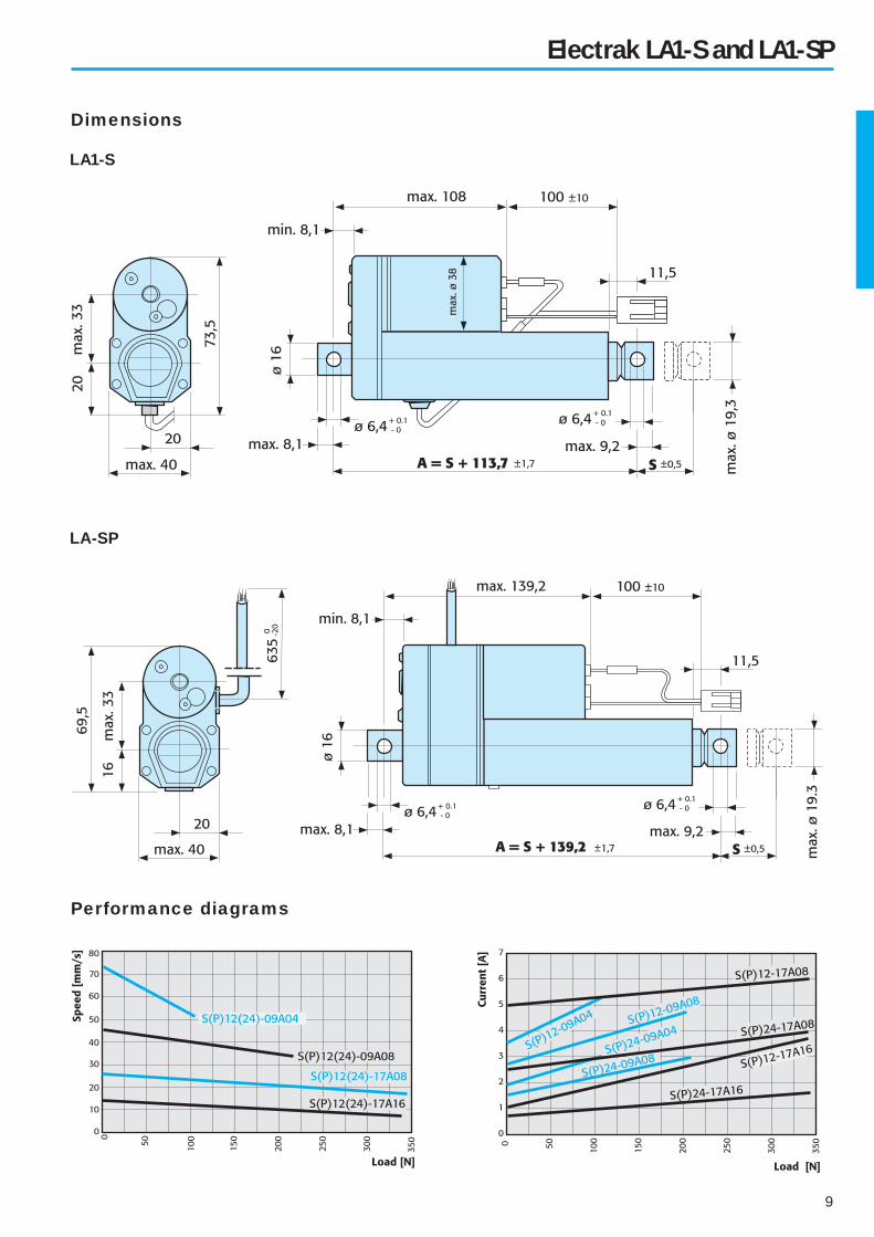
S(P)12–09A04 110 75 52
S(P)24–09A04 110 75 52
S(P)12–09A08 225 45 33
S(P)24–09A08 225 45 33
S(P)12–17A08 340 26 17
S(P)24–17A08 340 26 17
S(P)12–17A16 340 14 7
S(P)24–17A16 340 14 7
LA1-S
ordering
stroke
Actual stroke
S
[mm]
01 21
02 46
03 72
04 97
05 122
06 148
Standard strokesPerformance table
Features for LA1-S
Features for LA1-SP
Options
Engineering notes
LA1-SP
ordering
stroke
Actual stroke
S
[mm]
02 59
04 115
06 171
9
LA1-S
Dimensions
Electrak LA1 -S and LA1-SP
Performance diagrams
LA-SP

10
Electrak LA10
Available input voltages [Vdc] 12, 24 or 36
Available screw types Acme or Ball
Max. static load at fully retracted [N]
Acme screw models
Ball screw models
11 350
18 000
Min. / max. standard stroke [inch] 4 / 24
Duty cycle @ 25° C [%] 25
Temperature limits at operation [°C] - 25 to + 65
Protection degree IP65
Max. end play [mm] 1
Restraining torque [Nm] 11,3
Wire cross section [mm2] 2
Wire length [mm] 165
Connector included yes
Technical data Features
• Rugged and robust
• Weather resistant (IP65)
• Withstand 96 hour salt spray test
• Overload clutch (set to 1,2 – 1,5 × max. permissible load)
• Motor with auto reset thermal overload protection
• Acme or ball screw drive
• Holding brake prevents back driving on ball screw models
• Acme screw models are self-locking
• Safety nut on all ball screw models
• Can operate in a large temperature range
• Accepts large input voltage variations
• Maintenance free
• Potentiometer feedback
• Hand wind
• Custom RAL color
ModelMax.
dynamic
load [N]
Speed
@ min. load
[mm/s]
Speed
@ max. load
[mm/s]
D12–05A5 1100 54 32
D24–05A5 1100 54 32
D12–05B5 2250 61 37
D24–05B5 2250 61 37
D12–10A5 2250 30 18
D24–10A5 2250 30 18
D12–10B5 4500 30 19
D24–10B5 4500 30 19
D12–20A5 2250 15 12
D24–20A5 2250 15 12
D12–20B5 4500 15 12
D24–20B5 4500 15 12
D12–21B5 6800 15 11
D24–21B5 6800 15 11
Ordering
stroke
[inch]
Actual stroke
S
[mm]
4 102
6 152
8 203
10 254
12 305
14 356
16 406
18 457
20 508
24 610
Standard strokesPerformance table
Options
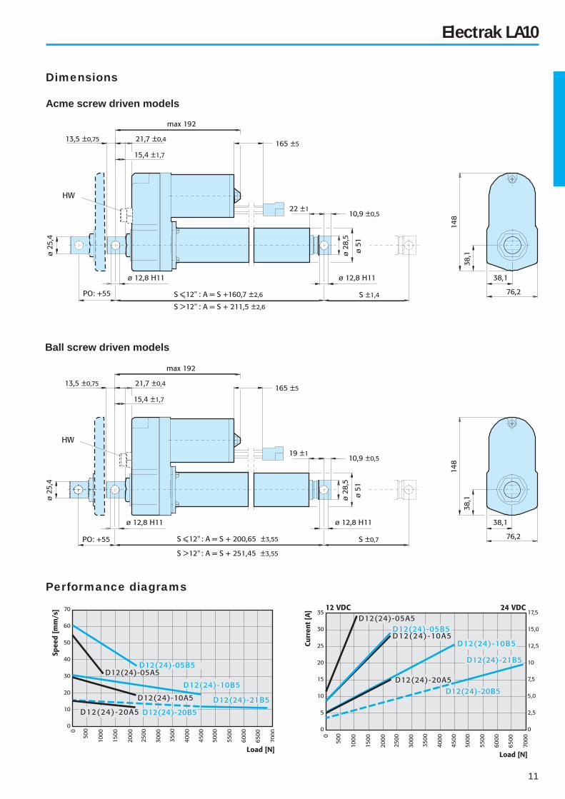
11
Ball screw driven models
Dimensions
Electrak LA10
Performance diagrams
Acme screw driven models

12
Electrak LA14
Available input voltages [Vdc] 12, 24 or 36
Available screw types Acme or Ball
Max. static load at fully retracted [N]
Acme screw models
Ball screw models
11 350
18 000
Min. / max. standard stroke [mm] 50 / 600
Duty cycle @ 25° C [%] 25
Temperature limits at operation [°C] - 25 to + 65
Protection degree IP65
Max. end play [mm] 1
Restraining torque [Nm] –
Wire cross section [mm2] 2
Wire length [mm] 165
Connector included yes
Technical data Features
• Rugged and robust
• Aluminium cover tube with T-slot
• Position sensors can be fi tted to the T-slots
• Trunnion mounting possible
• Anti rotation mechanism
• Weather resistant (IP65)
• Overload clutch (set to 1,2 – 1,5 × max. permissible load)
• Motor with auto reset thermal overload protection
• Acme or ball screw drive
• Holding brake prevents back driving on ball screw models
• Acme screw models are self-locking
• Safety nut on all ball screw models
• Can operate in a large temperature range
• Accepts large input voltage variations
• Maintenance free
Options
• Potentiometer feedback
• Hand wind
• Custom RAL color
ModelMax.
dynamic
load [N]
Speed
@ min. load
[mm/s]
Speed
@ max. load
[mm/s]
DA12–05A5 1100 54 32
DA24–05A5 1100 54 32
DA12–05B5 2250 61 37
DA24–05B5 2250 61 37
DA12–10A5 2250 30 18
DA24–10A5 2250 30 18
DA12–10B5 4500 30 19
DA24–10B5 4500 30 19
DA12–20A5 2250 15 12
DA24–20A5 2250 15 12
DA12–20B5 4500 15 12
DA24–20B5 4500 15 12
DA12–21B5 6800 15 11
DA24–21B5 6800 15 11
Ordering
stroke
[cm]
Actual stroke
S
[mm]
5 50
10 100
15 150
20 200
25 250
30 300
35 350
40 400
45 450
50 500
55 550
60 600
Standard strokesPerformance table
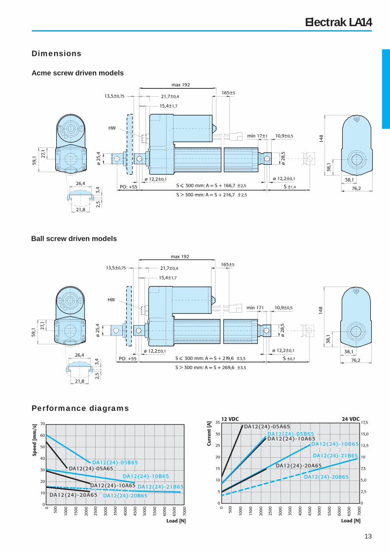
13
Ball screw driven models
Dimensions
Electrak LA14
Performance diagrams
Acme screw driven models

14
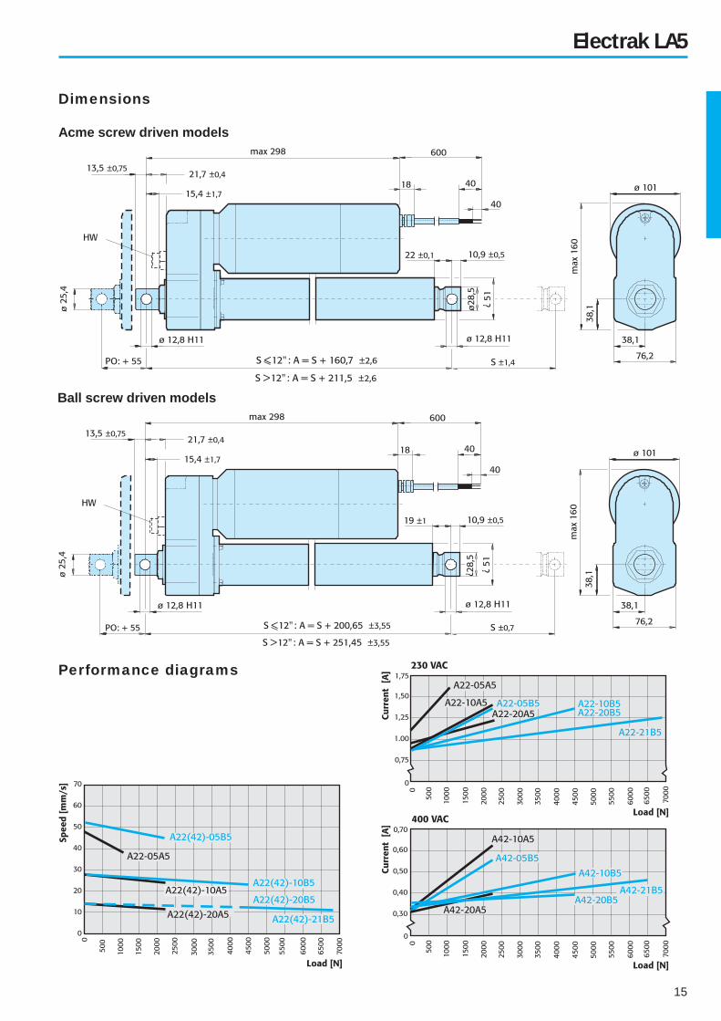
Electrak LA5
Available input voltages [Vac] 1 × 230 or 3 × 400
Input frequency [Hz] 50
Available screw types Acme or Ball
Max. static load at fully retracted [N]
Acme screw models
Ball screw models
11 350
18 000
Min. / max. standard stroke [inch] 4 / 24
Duty cycle @ 25° C [%] 25
Max. operation time [s] 45
Temperature limits at operation [°C] - 25 to + 65
Protection degree IP45
Max. end play [mm] 1
Restraining torque [Nm] 12
Wire cross section [mm2] 1,5
Wire length [mm] 600
Connector included no
Technical data Features
• Rugged and robust
• Overload clutch (set to 1,2 – 1,5 × max. permissible load)
• Motor with auto reset thermal overload protection
• Acme or ball screw drive
• Holding brake prevents back driving on ball screw models
• Acme screw models are self-locking
• Anti coast brake on all ball screw models (optional on
acme models)
• Safety nut on all ball screw models
• Can operate in a large temperature range
• Accepts large input voltage variations
• Maintenance free
• Potentiometer feedback
• Hand wind
• Custom RAL color
• Capacitor (10 µF) necessary on 230 Vac models,
p/no. D9200-448-003
ModelMax.
dynamic
load [N]
Speed
@ min. load
[mm/s]
Speed
@ max. load
[mm/s]
A22–05A5 1100 48 38
A22–05B5 2250 61 37
A42–05B5 2250 61 37
A22–10A5 2250 30 18
A42–10A5 2250 30 18
A22–10B5 4500 30 19
A42–10B5 4500 30 19
A22–20A5 2250 15 12
A42–20A5 2250 15 12
A22–20B5 4500 15 12
A42–20B5 4500 15 12
A22–21B5 6800 15 11
A42–21B5 6800 15 11
Ordering
stroke
[inch]
Actual stroke
S
[mm]
4 102
6 152
8 203
10 254
12 305
14 356
16 406
18 457
20 508
24 610
Standard strokesPerformance table
Engineering notes
Options
15
Ball screw driven models
Dimensions
Electrak LA5
Performance diagrams
Acme screw driven models
16
• Rugged and robust
• Aluminium cover tube with T-slot
• Position sensors can be fi tted to the T-slots
• Trunnion mounting possible
• Anti rotation mechanism
• Withstand 96 hour salt spray test
• Overload clutch (set to 1,2 – 1,5 × max. permissible load)
• Motor with auto reset thermal overload protection
• Acme or ball screw drive
• Holding brake prevents back driving on ball screw models
• Acme screw models are self-locking
• Safety nut on all ball screw models
• Can operate in a large temperature range
• Accepts large input voltage variations
• Maintenance free
• Potentiometer feedback
• Hand wind
• Custom RAL color
• Capacitor (10 µF) necessary on 230 Vac models
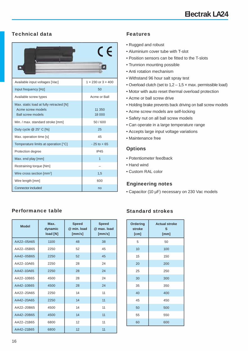
Electrak LA24
Available input voltages [Vac] 1 × 230 or 3 × 400
Input frequency [Hz] 50
Available screw types Acme or Ball
Max. static load at fully retracted [N]
Acme screw models
Ball screw models
11 350
18 000
Min. / max. standard stroke [mm] 50 / 600
Duty cycle @ 25° C [%] 25
Max. operation time [s] 45
Temperature limits at operation [°C] - 25 to + 65
Protection degree IP45
Max. end play [mm] 1
Restraining torque [Nm] –
Wire cross section [mm2] 1,5
Wire length [mm] 600
Connector included no
Technical data Features
Standard strokesPerformance table
Engineering notes
ModelMax.
dynamic
load [N]
Speed
@ min. load
[mm/s]
Speed
@ max. load
[mm/s]
AA22–05A65 1100 48 38
AA22–05B65 2250 52 45
AA42–05B65 2250 52 45
AA22–10A65 2250 28 24
AA42–10A65 2250 28 24
AA22–10B65 4500 28 24
AA42–10B65 4500 28 24
AA22–20A65 2250 14 11
AA42–20A65 2250 14 11
AA22–20B65 4500 14 11
AA42–20B65 4500 14 11
AA22–21B65 6800 12 11
AA42–21B65 6800 12 11
Ordering
stroke
[cm]
Actual stroke
S
[mm]
5 50
10 100
15 150
20 200
25 250
30 300
35 350
40 400
45 450
50 500
55 550
60 600
Options
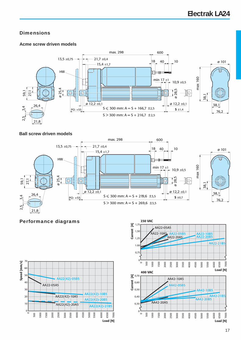
17
Ball screw driven models
Electrak LA24
Performance diagrams
Acme screw driven models
Dimensions

18
• Rugged and robust
• Motor fi tted by customer
• Aluminium cover tube with T-slot
• Position sensors can be fi tted to the T-slots
• Trunnion mounting possible
• Anti rotation mechanism
• Overload clutch (set to 1,2 – 1,5 × max. permissible load)
• Acme or ball screw drive
• Holding brake prevents back driving on ball screw models
• Acme screw models are self-locking
• Safety nut on all ball screw models
• Maintenance free
• Hand wind
• Custom RAL color
Electrak FA14 (no motor)
Available screw types Acme or Ball
Max. static load at fully retracted [N]
Acme screw models
Ball screw models
11 350
18 000
Min. / max. standard stroke [mm] 100 / 600
Max. input speed [rpm] 3000
Max. input torque [Nm] 1,8
Max. end play [mm] 1
Restraining torque [Nm] –
Technical data Features
Standard strokesPerformance table
ModelMax.
dynamic
load [N]
Speed
@ max. load
[mm/s]*
FA14–05A65 1100 32
FA14–05B65 2250 37
FA14–10A65 2250 18
FA14– 0B65 4500 19
FA14–20A65 2250 12
FA14–20B65 4500 12
FA14–21B65 6800 11
Ordering
stroke
[cm]
Actual stroke
S
[mm]
5 50
10 100
15 150
20 200
25 250
30 300
35 350
40 400
45 450
50 500
55 550
60 600
Options
*Recommended value

19
Ball screw driven models
Dimensions
Electrak FA14 (no motor)
Acme screw driven models

20
Designation example S 12 – 09A04 – 02
Electrak LA1-S
Actuator type
LA1-S (with end of stroke limit switches) S
Supply voltage
12 Vdc
24 Vdc
36 Vdc
12
24
36
Hyphen –
Gear ratio / screw type / screw lead
9:1 / acme screw / 6,35 mm
9:1 / acme screw / 3,18 mm
17:1 / acme screw / 3,18 mm
17:1 / acme screw / 1,59 mm
09A04
09A08
17A08
17A16
Hyphen –
Stroke
21 mm
46 mm
72 mm
97 mm
122 mm
148 mm
01
02
03
04
05
06
Ordering keys
Designation example SP 12 – 09A04 – 02
Electrak LA1-SP
Actuator type
LA1-SP (with feedback potentiometer) SP
Supply voltage
12 Vdc
24 Vdc
36 Vdc
12
24
36
Hyphen –
Gear ratio / screw type / screw lead
9:1 / acme screw / 6,35 mm
9:1 / acme screw / 3,18 mm
17:1 / acme screw / 3,18 mm
17:1 / acme screw / 1,59 mm (not possible with 171,5 mm stroke)
09A04
09A08
17A08
17A16
Hyphen –
Stroke
59 mm
115 mm
172 mm (not possible with gear and screw combination 17A16)
02
04
06

21
Ordering keys
Designation example D 24 – 10B5 – 06 M0 N
Electrak LA10
Actuator type
LA10 D
Supply voltage
12 Vdc
24 Vdc
36 Vdc
12
24
36
Hyphen –
Gear ratio / screw type / screw lead
5:1 / acme screw / 5,08 mm
10:1 / acme screw / 5,08 mm
20:1 / acme screw / 5,08 mm
5:1 / ball screw / 5,08 mm
10:1 / ball screw / 5,08 mm
20:1 / ball screw / 5,08 mm
20:1 / ball screw / 5,08 mm with hardened gear
05A5
10A5
20A5
05B5
10B5
20B5
21B5
Engineering unit
Inch –
Stroke
4 inch (102 mm)
6 inch (152 mm)
8 inch (203 mm)
10 inch (254 mm)
12 inch (305 mm)
14 inch (356 mm)
16 inch (406 mm)
18 inch (457 mm)
20 inch (508 mm)
24 inch (610 mm)
04
06
08
10
12
14
16
18
20
24
Adaptor hole position (for defi nition see page 26)
Rear adaptor 0° (standard position)
Rear adaptor 30°
Rear adaptor 60°
Rear adaptor 90°
Rear adaptor 120°
Rear adaptor 150°
M0
M1
M2
M3
M4
M5
Anti coast brake
No anti coast brake N
Options
No option - leave position blank
Feedback potentiometer
Hand wind
PO
HW
22
Ordering keys
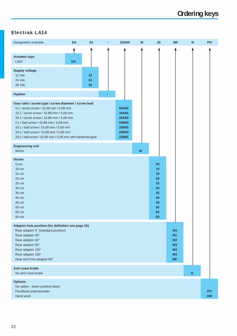
Designation example DA 24 – 20A65 M 25 MF N PO
Electrak LA14
Actuator type
LA14 DA
Supply voltage
12 Vdc
24 Vdc
36 Vdc
12
24
36
Hyphen –
Gear ratio / screw type / screw diameter / screw lead
5:1 / acme screw / 15,88 mm / 5,08 mm
10:1 / acme screw / 15,88 mm / 5,08 mm
20:1 / acme screw / 15,88 mm / 5,08 mm
5:1 / ball screw / 15,88 mm / 5,08 mm
10:1 / ball screw / 15,88 mm / 5,08 mm
20:1 / ball screw / 15,88 mm / 5,08 mm
20:1 / ball screw / 15,88 mm / 5,08 mm with hardened gear
05A65
10A65
20A65
05B65
10B65
20B65
21B65
Engineering unit
Metric M
Stroke
5 cm
10 cm
15 cm
20 cm
25 cm
30 cm
35 cm
40 cm
45 cm
50 cm
55 cm
60 cm
05
10
15
20
25
30
35
40
45
50
55
60
Adaptor hole position (for defi nition see page 26)
Rear adaptor 0° (standard position)
Rear adaptor 30°
Rear adaptor 60°
Rear adaptor 90°
Rear adaptor 120°
Rear adaptor 150°
Rear and front adaptor 90°
M0
M1
M2
M3
M4
M5
MF
Anti coast brake
No anti coast brake N
Options
No option - leave position blank
Feedback potentiometer
Hand wind
PO
HW

23
Ordering keys
Designation example A 22 – 10B5 – 04 M0 B HW
Electrak LA5
Actuator type
LA5 A
Supply voltage
1 × 230 Vac, 50 Hz
3 × 400 Vac, 50 Hz
22
42
Hyphen –
Gear ratio / screw type / screw diameter / screw lead
5:1 / acme screw / 15,88 mm / 5,08 mm (not possible with 400 Vac motor)
10:1 / acme screw / 15,88 mm / 5,08 mm
20:1 / acme screw / 15,88 mm / 5,08 mm
5:1 / ball screw / 15,88 mm / 5,08 mm
10:1 / ball screw / 15,88 mm / 5,08 mm
20:1 / ball screw / 15,88 mm / 5,08 mm
20:1 / ball screw / 15,88 mm / 5,08 mm with hardened gear
05A5
10A5
20A5
05B5
10B5
20B5
21B5
Engineering unit
Inch –
Stroke
4 inch (102 mm)
6 inch (152 mm)
8 inch (203 mm)
10 inch (254 mm)
12 inch (305 mm)
14 inch (356 mm)
16 inch (406 mm)
18 inch (457 mm)
20 inch (508 mm)
24 inch (610 mm)
04
06
08
10
12
14
16
18
20
24
Adaptor hole position (for defi nition see page 26)
Rear adaptor 0° (standard position)
Rear adaptor 30°
Rear adaptor 60°
Rear adaptor 90°
Rear adaptor 120°
Rear adaptor 150°
M0
M1
M2
M3
M4
M5
Anti coast brake
No anti coast brake
Anti coast brake
N
B
Options
No option - leave position blank
Feedback potentiometer
Hand wind
PO
HW

24
Ordering keys
Designation example AA 42 – 20A65 M 30 M3 N HW
Electrak LA24
Actuator type
LA24 AA
Supply voltage
1 × 230 Vac, 50 Hz
3 × 400 Vac, 50 Hz
22
42
Hyphen –
Gear ratio / screw type / screw diameter / screw lead
5:1 / acme screw / 15,88 mm / 5,08 mm (not possible with 400 Vac motor)
10:1 / acme screw / 15,88 mm / 5,08 mm
20:1 / acme screw / 15,88 mm / 5,08 mm
5:1 / ball screw / 15,88 mm / 5,08 mm
10:1 / ball screw / 15,88 mm / 5,08 mm
20:1 / ball screw / 15,88 mm / 5,08 mm
20:1 / ball screw / 15,88 mm / 5,08 mm with hardened gear
05A65
10A65
20A65
05B65
10B65
20B65
21B65
Engineering unit
Metric M
Stroke
5 cm
10 cm
15 cm
20 cm
25 cm
30 cm
35 cm
40 cm
45 cm
50 cm
55 cm
60 cm
05
10
15
20
25
30
35
40
45
50
55
60
Adaptor hole position (for defi nition see page 26)
Rear adaptor 0° (standard position)
Rear adaptor 30°
Rear adaptor 60°
Rear adaptor 90°
Rear adaptor 120°
Rear adaptor 150°
Rear and front adaptor 90°
M0
M1
M2
M3
M4
M5
MF
Anti coast brake
No anti coast brake
Anti coast brake
N
B
Options
No option - leave position blank
Feedback potentiometer
Hand wind
PO
HW
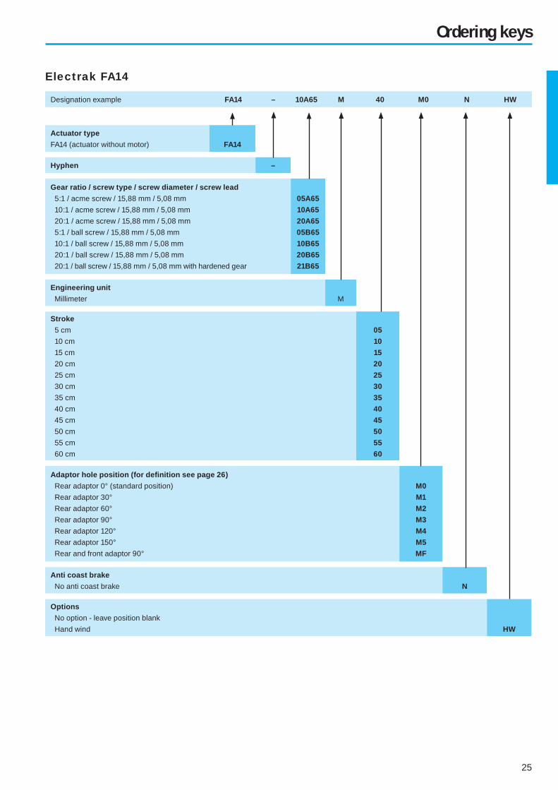
25
Ordering keys
Electrak FA14
Designation example FA14 – 10A65 M 40 M0 N HW
Actuator type
FA14 (actuator without motor) FA14
Hyphen –
Gear ratio / screw type / screw diameter / screw lead
5:1 / acme screw / 15,88 mm / 5,08 mm
10:1 / acme screw / 15,88 mm / 5,08 mm
20:1 / acme screw / 15,88 mm / 5,08 mm
5:1 / ball screw / 15,88 mm / 5,08 mm
10:1 / ball screw / 15,88 mm / 5,08 mm
20:1 / ball screw / 15,88 mm / 5,08 mm
20:1 / ball screw / 15,88 mm / 5,08 mm with hardened gear
05A65
10A65
20A65
05B65
10B65
20B65
21B65
Engineering unit
Millimeter M
Stroke
5 cm
10 cm
15 cm
20 cm
25 cm
30 cm
35 cm
40 cm
45 cm
50 cm
55 cm
60 cm
05
10
15
20
25
30
35
40
45
50
55
60
Adaptor hole position (for defi nition see page 26)
Rear adaptor 0° (standard position)
Rear adaptor 30°
Rear adaptor 60°
Rear adaptor 90°
Rear adaptor 120°
Rear adaptor 150°
Rear and front adaptor 90°
M0
M1
M2
M3
M4
M5
MF
Anti coast brake
No anti coast brake N
Options
No option - leave position blank
Hand wind HW
26
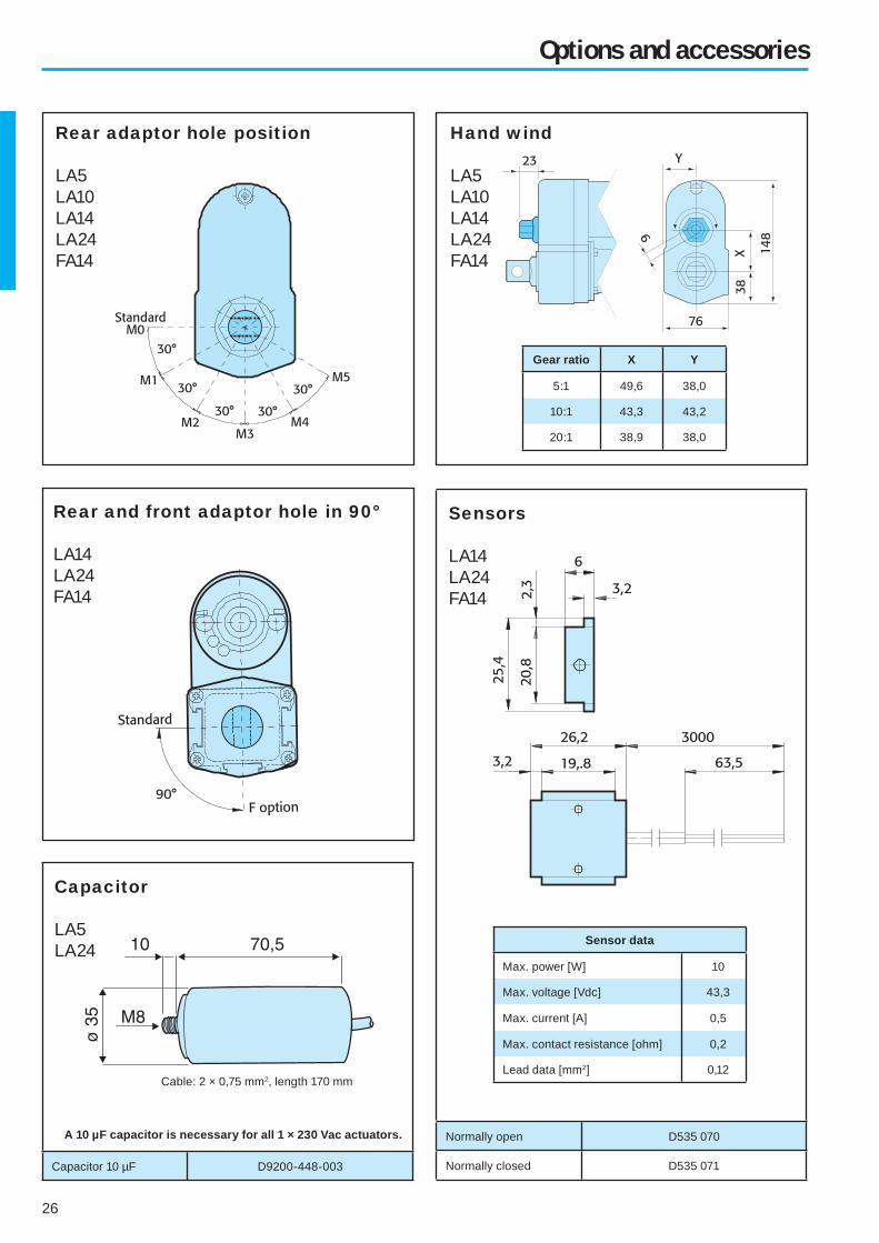
Cable: 2 × 0,75 mm2, length 170 mm
A 10 µF capacitor is necessary for all 1 × 230 Vac actuators.
Capacitor 10 µF D9200-448-003
Options and accessories
Rear adaptor hole position
LA5LA10LA14LA24FA14
Rear and front adaptor hole in 90°
LA14LA24FA14
Hand wind
LA5LA10LA14LA24FA14
Capacitor
LA5LA24
Normally open D535 070
Normally closed D535 071
Gear ratio X Y
5:1 49,6 38,0
10:1 43,3 43,2
20:1 38,9 38,0
Sensors
LA14LA24FA14
Sensor data
Max. power [W] 10
Max. voltage [Vdc] 43,3
Max. current [A] 0,5
Max. contact resistance [ohm] 0,2
Lead data [mm2] 0,12
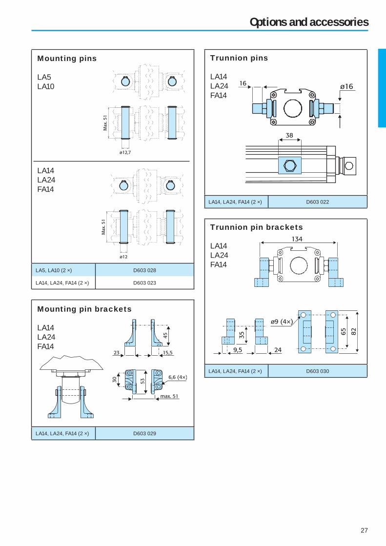
27
LA14, LA24, FA14 (2 ×) D603 029
LA5, LA10 (2 ×) D603 028
LA14, LA24, FA14 (2 ×) D603 023
Options and accessories
Mounting pin brackets
LA14LA24FA14
Mounting pins
LA5LA10
LA14LA24FA14
LA14, LA24, FA14 (2 ×) D603 022
Trunnion pins
LA14LA24FA14
LA14, LA24, FA14 (2 ×) D603 030
Trunnion pin brackets
LA14LA24FA14

28
– Page intentionally left blank –

29
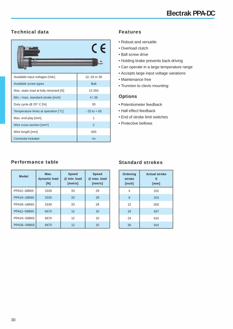
Elektrak PPA-DC
• Robust and vesatile
• Trunnion to clevis mounting
• 12, 24 or 36 Vdc
• Ball screw driven
• Stroke from 102 to 914 mm
• Speed from 12 to 33 mm/s
Electrak PPA-series
• Robust and vesatile
• Trunnion to clevis mounting
• 110 or 230 Vac power supply
• Ball screw driven
• Stroke from 102 to 914 mm
• Speed from 5 to 15 mm/s
Elektrak PPA-AC
• Load up to 6670 N
• Maintenance free
• End of stroke limit switches available as option
• Feedback potentiometer available as option
• Hall effect position sensor available as option
• Load up to 6670 N
• Motor with auto reset thermal overload protection
• Maintenance free
• End of stroke limit switches available as option
• Feedback potentiometer available as option
• Hall effect position sensor available as option
30
Available input voltages [Vdc] 12, 24 or 36
Available screw types Ball
Max. static load at fully retracted [N] 13 350
Min. / max. standard stroke [inch] 4 / 36
Duty cycle @ 20° C [%] 30
Temperature limits at operation [°C] - 25 to + 65
Max. end play [mm] 1
Wire cross section [mm2] 2
Wire length [mm] 400
Connector included no
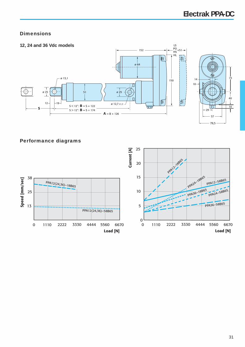
Electrak PPA-DC
Technical data Features
• Robust and versatile
• Overload clutch
• Ball screw drive
• Holding brake prevents back driving
• Can operate in a large temperature range
• Accepts large input voltage variations
• Maintenance free
• Trunnion to clevis mounting
• Potentiometer feedback
• Hall effect feedback
• End of stroke limit switches
• Protective bellows
ModelMax.
dynamic load
[N]
Speed
@ min. load
[mm/s]
Speed
@ max. load
[mm/s]
PPA12–18B65 3330 33 28
PPA24–18B65 3330 33 28
PPA36–18B65 3330 33 28
PPA12–58B65 6670 12 10
PPA24–58B65 6670 12 10
PPA36–58B65 6670 12 10
Ordering
stroke
[inch]
Actual stroke
S
[mm]
4 102
8 203
12 305
18 457
24 610
36 914
Standard strokesPerformance table
Options
31
Electrak PPA-DC
Performance diagrams
Dimensions
12, 24 and 36 Vdc models

32
Available input voltages [Vac] 1 × 110 or 1 × 230
Input frequency [Hz] 50 / 60
Available screw types Ball
Max. static load at fully retracted [N] 13 350
Min. / max. standard stroke [inch] 4 / 36
Max. coast distance (without anti coast or
electrical brake option) [mm] 1,6
Duty cycle @ 20° C [%] 30
Temperature limits at operation [°C] - 25 to + 65
Max. end play [mm] 1
Wire cross section [mm2] 0,75
Wire length [mm] 500
Connector included no
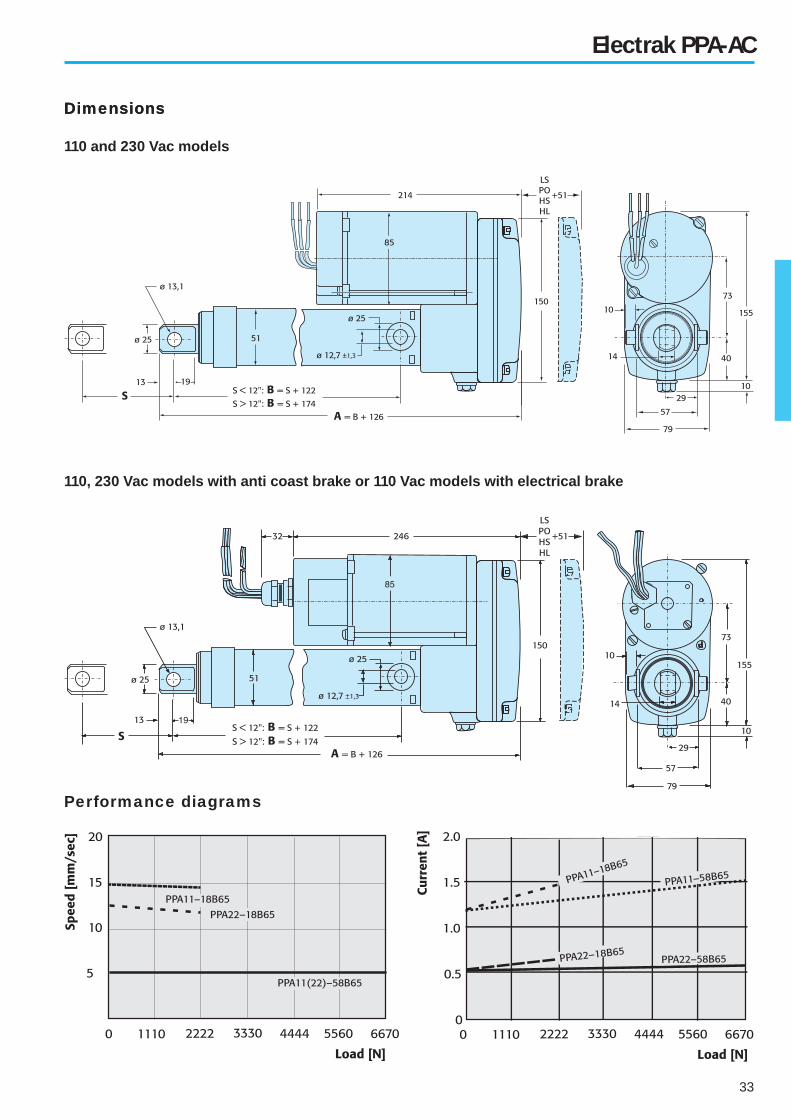
Electrak PPA-AC
Technical data Features
• Robust and versatile
• Overload clutch
• Motor with auto reset thermal overload protection
• Ball screw drive
• Holding brake prevents back driving
• Can operate in a large temperature range
• Accepts large input voltage variations
• Maintenance free
• Built in capacitor
• Trunnion to clevis mounting
• Anti coast brake on 110 and 230 Vac models
• Electrical brake on 110 Vac models
• Potentiometer feedback
• Hall effect feedback
• End of stroke limit switches
• Protective bellows
ModelMax.
dynamic load
[N]
Speed
@ min. load
[mm/s]
Speed
@ max. load
[mm/s]
PPA11–18B65 2220 15 14
PPA22–18B65 2220 12,5 12
PPA11–58B65 6670 5 5
PPA22–58B65 6670 5 5
Ordering
stroke
[inch]
Actual stroke
S
[mm]
4 102
8 203
12 305
18 457
24 610
36 914
Standard strokesPerformance table
Options
33
Electrak PPA-AC
Dimensions
Performance diagrams
Dimensions
110 and 230 Vac models
110, 230 Vac models with anti coast brake or 110 Vac models with electrical brake
34
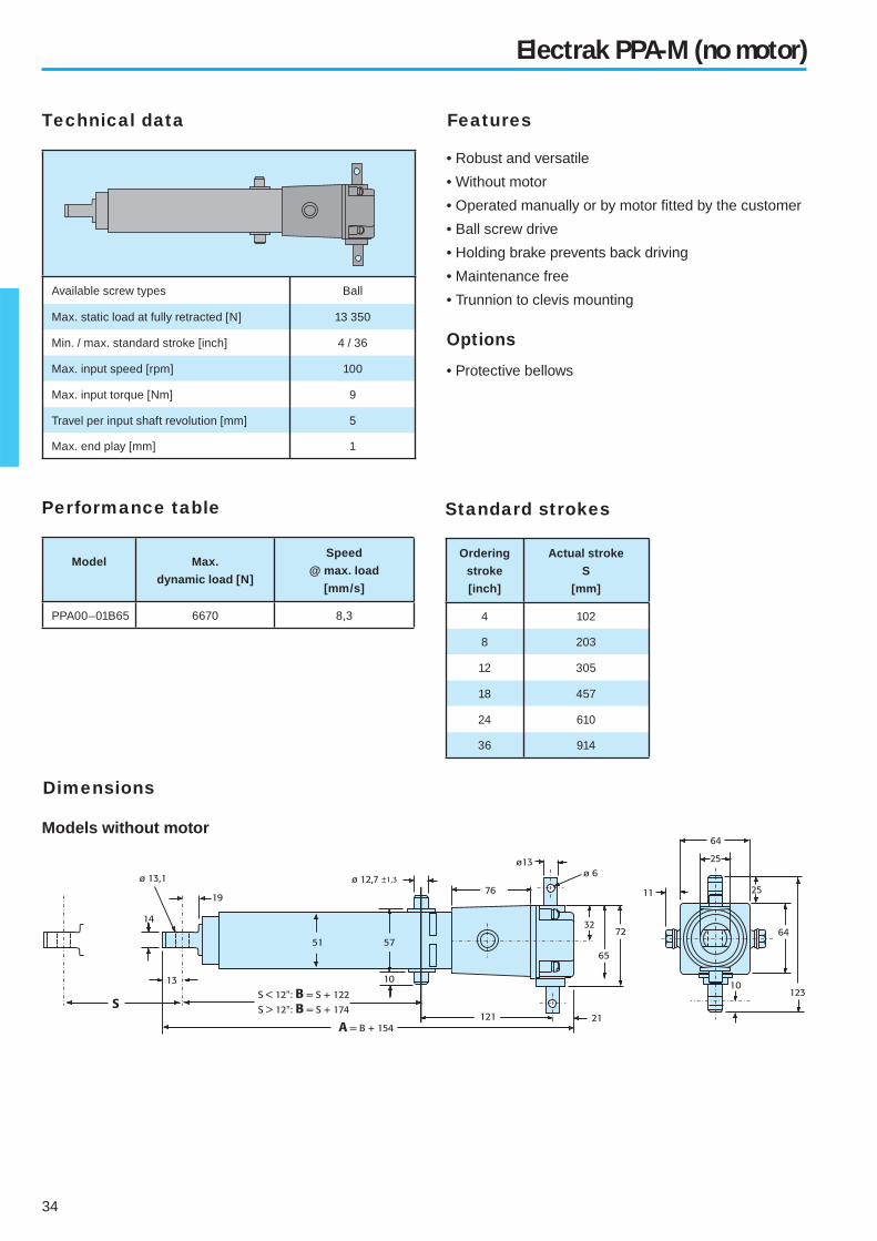
Available screw types Ball
Max. static load at fully retracted [N] 13 350
Min. / max. standard stroke [inch] 4 / 36
Max. input speed [rpm] 100
Max. input torque [Nm] 9
Travel per input shaft revolution [mm] 5
Max. end play [mm] 1
Electrak PPA-M (no motor)
Models without motor
Dimensions
Technical data Features
• Robust and versatile
• Without motor
• Operated manually or by motor fi tted by the customer
• Ball screw drive
• Holding brake prevents back driving
• Maintenance free
• Trunnion to clevis mounting
• Protective bellows
Ordering
stroke
[inch]
Actual stroke
S
[mm]
4 102
8 203
12 305
18 457
24 610
36 914
Standard strokes
Model Max.
dynamic load [N]
Speed
@ max. load
[mm/s]
PPA00–01B65 6670 8,3
Performance table
Options
35
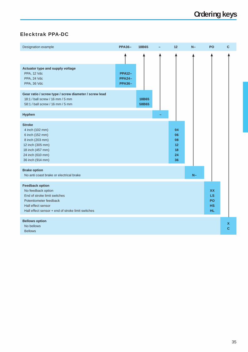
Ordering keys
Elecktrak PPA-DC
Designation example PPA36– 18B65 – 12 N– PO C
Actuator type and supply voltage
PPA, 12 Vdc
PPA, 24 Vdc
PPA, 36 Vdc
PPA12–
PPA24–
PPA36–
Gear ratio / screw type / screw diameter / screw lead
18:1 / ball screw / 16 mm / 5 mm
58:1 / ball screw / 16 mm / 5 mm
18B65
58B65
Hyphen –
Stroke
4 inch (102 mm)
6 inch (152 mm)
8 inch (203 mm)
12 inch (305 mm)
18 inch (457 mm)
24 inch (610 mm)
36 inch (914 mm)
04
06
08
12
18
24
36
Brake option
No anti coast brake or electrical brake N–
Feedback option
No feedback option
End of stroke limit switches
Potentiometer feedback
Hall effect sensor
Hall effect sensor + end of stroke limit switches
XX
LS
PO
HS
HL
Bellows option
No bellows
Bellows
X
C

36
Ordering keys
Elecktrak PPA-AC
Designation example PPA22– 58B65 – 06 SB XX X
Actuator type and supply voltage
PPA, 1 × 110 Vac, 50/60 Hz
PPA, 1 × 230 Vac, 50/60 Hz
PPA11–
PPA22–
Gear ratio / screw type / screw diameter / screw lead
18:1 / ball screw / 16 mm / 5 mm
58:1 / ball screw / 16 mm / 5 mm
18B65
58B65
Hyphen –
Stroke
4 inch (102 mm)
6 inch (152 mm)
8 inch (203 mm)
12 inch (305 mm)
18 inch (457 mm)
24 inch (610 mm)
36 inch (914 mm)
04
06
08
12
18
24
36
Brake option
No anti coast brake or electrical brake
Anti coast brake
Electrical brake (only possible on 110 Vac models)
N–
SB
EB
Feedback option
No feedback option
End of stroke limit switches
Potentiometer feedback
Hall effect sensor
Hall effect sensor + end of stroke limit switches
XX
LS
PO
HS
HL
Bellows option
No bellows
Bellows
X
C
37
Ordering keys
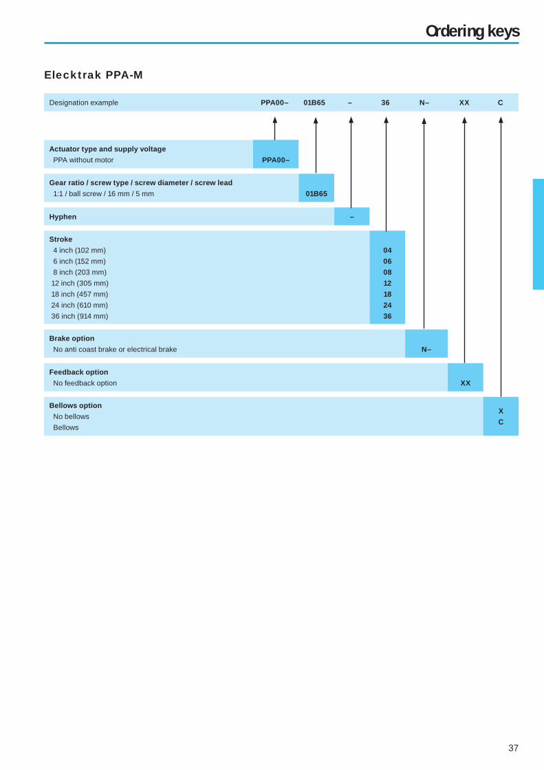
Elecktrak PPA-M
Designation example PPA00– 01B65 – 36 N– XX C
Actuator type and supply voltage
PPA without motor PPA00–
Gear ratio / screw type / screw diameter / screw lead
1:1 / ball screw / 16 mm / 5 mm 01B65
Hyphen –
Stroke
4 inch (102 mm)
6 inch (152 mm)
8 inch (203 mm)
12 inch (305 mm)
18 inch (457 mm)
24 inch (610 mm)
36 inch (914 mm)
04
06
08
12
18
24
36
Brake option
No anti coast brake or electrical brake N–
Feedback option
No feedback option XX
Bellows option
No bellows
Bellows
X
C

38
– Page intentionally left blank –

39
Electrak E-series
Electrak E050
Electrak E150
• Small, low noise and lightweight
• Shortest retracted length in the industry
• Low cost
• Load up to 510 N
• 12, 24 or 36 Vdc power supply
• Stroke from 25 to 200 mm
• Speed up to 48 mm/s
• IP 56
• Overload clutch
• End of stroke limit switches available as option
• Potentiometer feedback available as option
• LIghtweight, fl exible and durable
• Load up to 2000 N
• Speed up to 71 mm/s
• 12, 24 or 36 Vdc power supply
• Stroke from 100 to 400 mm
• IP56
Electrak Q050
• Share most features and technical data with E050
• Quiet operation
• Speed up to 38 mm/s
• IP 51
• Adjustable end of stroke limit switches available as option
• Potentiometer feedback available as option

40
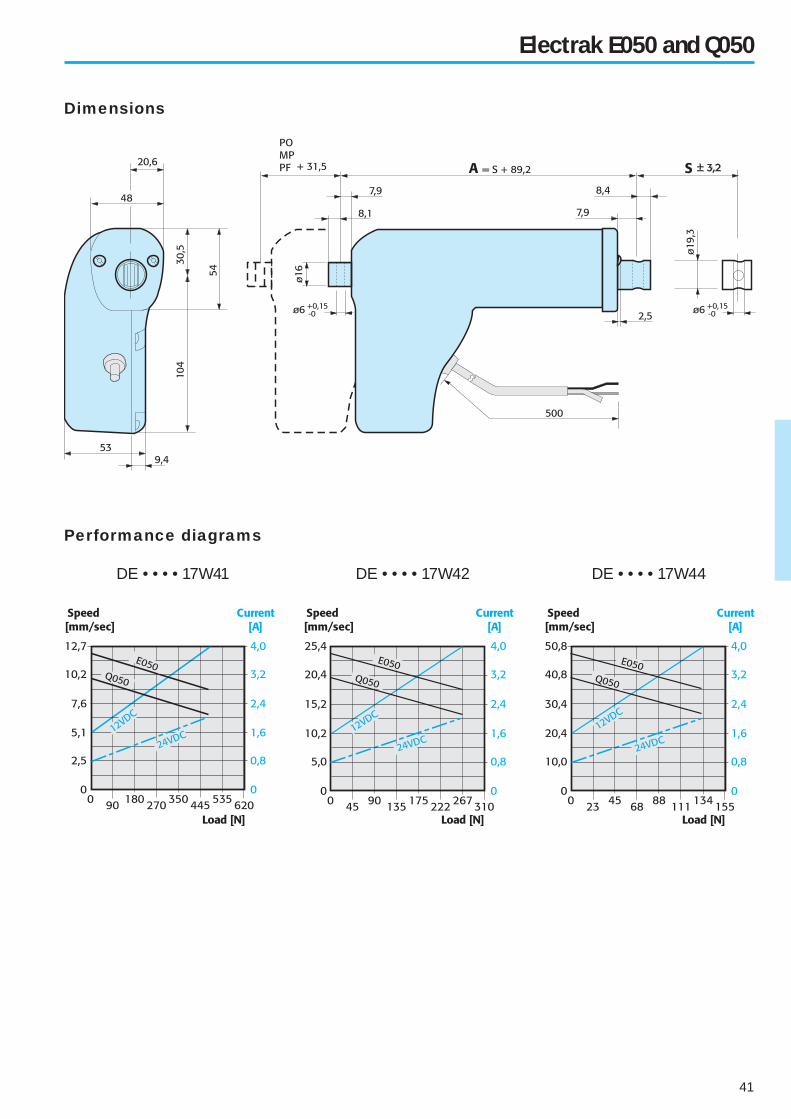
Electrak E050 and Q050
Available input voltages [Vdc] 12, 24 or 36
Screw type Worm
Max. static load at fully retracted [N]
DE • • • 17W41
DE • • • 17W42
DE • • • 17W44
1020
550
280
Min. / max. standard stroke [mm] 25 / 200
Duty cycle @ 20° C [%] 25
Temperature limits at operation [°C] - 30 to + 80
Protection degree
E050
Q050
IP56
IP51
Max. end play [mm] 1,5
Restraining torque [Nm] –
Wire cross section [mm2] 1
Wire length [mm] 500
Connector included no
Technical data Features for both E050 and Q050
• Small, quiet and lightweight
• Overload clutch
• Motor with auto reset thermal overload protection
• Anti rotation mechanism
• Estimated life is min. 40 000 cycles
• Vent tube
• Can operate in a large temperature range
• Accepts large input voltage variations
• Maintenance free
• End of stroke limit switches
• Potentiometer feedback
• Speed up to 48 mm/s
• Black housing
• IP56
• Quiet
• Speed up to 38 mm/s
• White housing
• IP51
ModelMax.
dynamic
load [N]
Speed
@ min. load
[mm/s]
Speed
@ max. load
[mm/s]
DE12–17W41 510 12 9
DE24–17W41 510 12 9
DE12–17W42 275 24 18
DE24–17W42 275 24 18
DE12–17W44 140 48 37
DE24–17W44 140 48 37
DE12Q17W41 510 9 7,5
DE24Q17W41 510 9 7,5
DE12Q17W42 275 18 14
DE24Q17W42 275 18 14
DE12Q17W44 140 38 30
DE24Q17W44 140 38 30
Ordering
stroke
[mm]
Actual stroke
S
[mm]
25 25
50 50
75 75
100 100
125 125
150 150
175 175
200* 200
Standard strokesPerformance table
Features for E050
Features for Q050
Options
*Not possible with option PO, PF and MP.
41
Dimensions
Electrak E050 and Q050
Performance diagrams
DE • • • • 17W41 DE • • • • 17W42 DE • • • • 17W44

42
Available input voltages [Vdc] 12, 24 or 36
Screw type Worm
Max. static load at fully retracted [N]
DF • • • 10W51
DF • • • 10W52
DF • • • 10W54
4000
2000
1000
Min. / max. standard stroke [mm] 100 / 400
Duty cycle @ 20° C [%] 25
Temperature limits at operation [°C] - 30 to + 65
Protection degree IP56
Max. end play [mm]
DF • • • 10W51
DF • • • 10W52
DF • • • 10W54
0,5
0,5
1,2
Stall current [A]
DF12
DF24
DF36
50
25
17
Restraining torque [Nm] –
Wire cross section [mm2] 1,5
Wire length [mm] 1000
Connector included on request
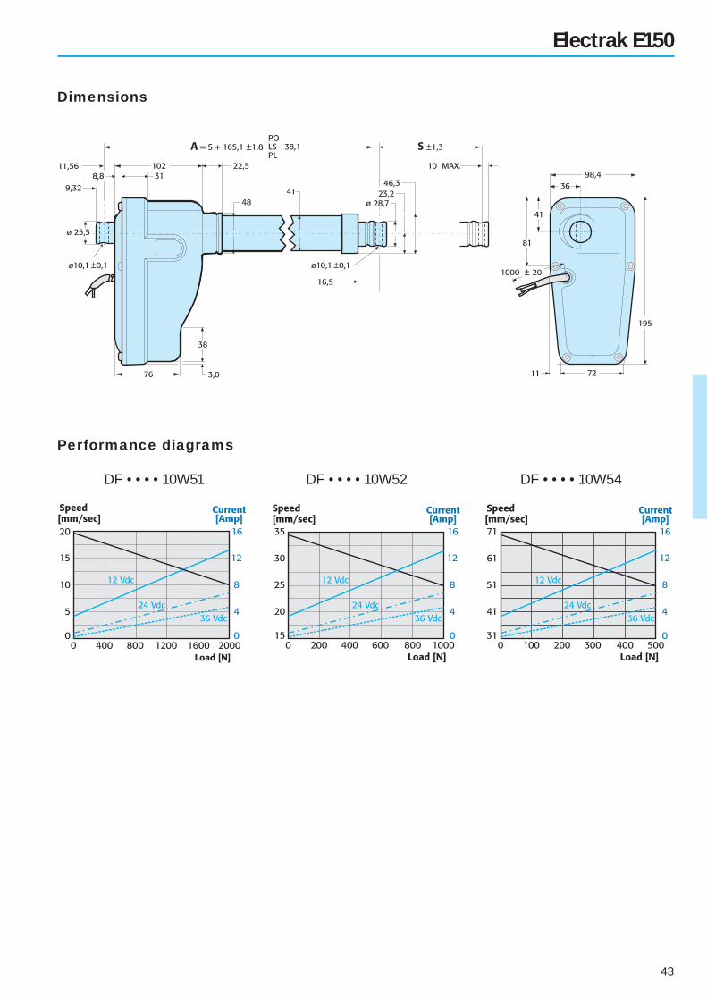
Electrak E150
Technical data Features
• Lightweight, fl exible and durable
• Motor with auto reset thermal overload protection
• Anti rotation mechanism
• Estimated life is min. 40 000 cycles
• Vent tube
• Can operate in a large temperature range
• Speed up to 70 mm/s
• IP56
• Accepts large input voltage variations
• Maintenance free
• Adjustable end of stroke limit switches
• Potentiometer feedback
• No clutch
Engineering notes
ModelMax.
dynamic
load [N]
Speed
@ min. load
[mm/s]
Speed
@ max. load
[mm/s]
DF12–10W51 2000 19 13
DF24–10W51 2000 19 13
DF36–10W51 2000 19 13
DF12– 10W52 1000 35 25
DF24–10W52 1000 35 25
DF36–10W52 1000 35 25
DF12–10W54 500 71 51
DF24–10W54 500 71 51
DF36–10W54 500 71 51
Ordering
stroke
[cm]
Actual stroke
S
[mm]
10 100
15 150
20 100
25 250
30 300
35 350
40 400
Standard strokesPerformance table
Options
43
Dimensions
Electrak E150
Performance diagrams
DF • • • • 10W51 DF • • • • 10W52 DF • • • • 10W54
44
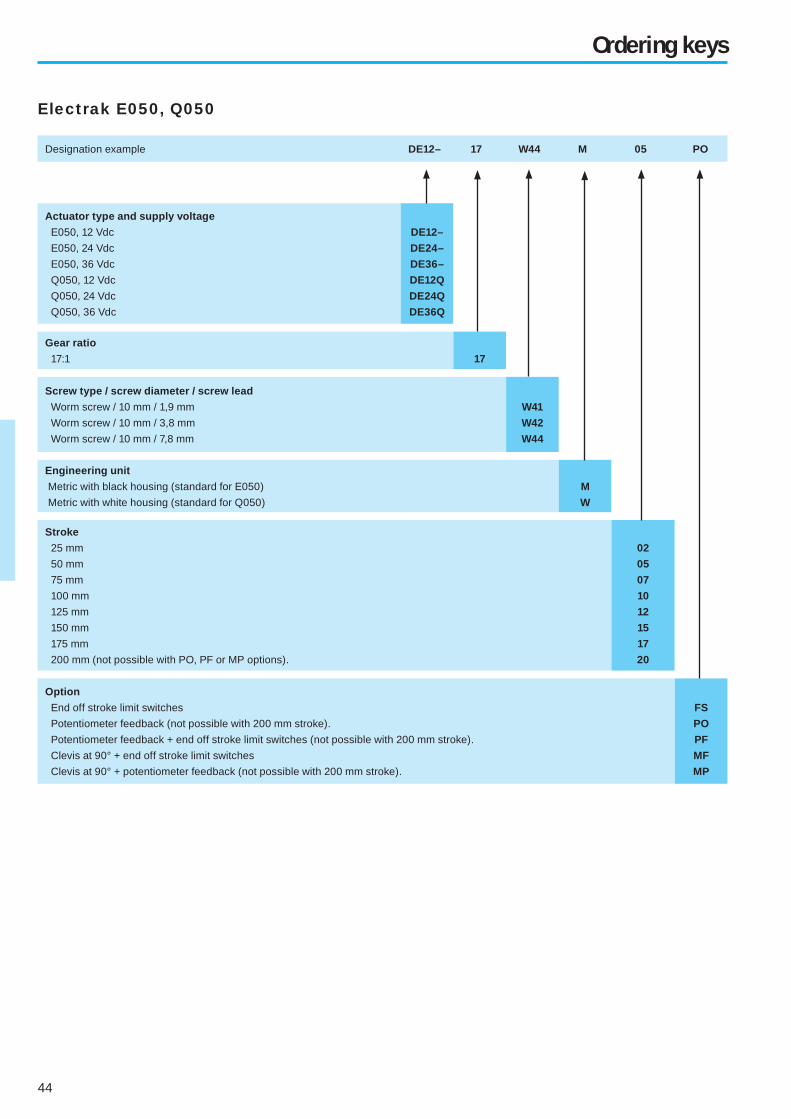
Ordering keys
Electrak E050, Q050
Designation example DE12– 17 W44 M 05 PO
Actuator type and supply voltage
E050, 12 Vdc
E050, 24 Vdc
E050, 36 Vdc
Q050, 12 Vdc
Q050, 24 Vdc
Q050, 36 Vdc
DE12–
DE24–
DE36–
DE12Q
DE24Q
DE36Q
Gear ratio
17:1 17
Screw type / screw diameter / screw lead
Worm screw / 10 mm / 1,9 mm
Worm screw / 10 mm / 3,8 mm
Worm screw / 10 mm / 7,8 mm
W41
W42
W44
Engineering unit
Metric with black housing (standard for E050)
Metric with white housing (standard for Q050)
M
W
Stroke
25 mm
50 mm
75 mm
100 mm
125 mm
150 mm
175 mm
200 mm (not possible with PO, PF or MP options).
02
05
07
10
12
15
17
20
Option
End off stroke limit switches
Potentiometer feedback (not possible with 200 mm stroke).
Potentiometer feedback + end off stroke limit switches (not possible with 200 mm stroke).
Clevis at 90° + end off stroke limit switches
Clevis at 90° + potentiometer feedback (not possible with 200 mm stroke).
FS
PO
PF
MF
MP

45
Ordering keys
Designation example DF12 – 10 W52 M 25 PL
Electrak E150
Actuator type and supply voltage
E150, 12 Vdc
E150, 24 Vdc
E150, 36 Vdc
DF12
DF24
DF36
Hyphen –
Gear ratio
10:1 10
Screw type / screw diameter / screw lead
Worm screw / 14 mm / 2,9 mm
Worm screw / 14 mm / 5,8 mm
Worm screw / 14 mm / 12,2 mm
W51
W52
W54
Engineering unit
Metric M
Stroke
100 mm
150 mm
200 mm
250 mm
300 mm
350 mm
400 mm
10
15
20
25
30
35
40
Option
Adjustable end off stroke limit switches
Potentiometer feedback
Potentiometer feedback + adjustable end off stroke limit switches
Clevis at 90°
Clevis at 90° + adjustable end off stroke limit switches
Clevis at 90° + potentiometer feedback
LS
PO
PL
M3
ML
MP

46
– Page intentionally left blank –
47
Movoact lifting columns
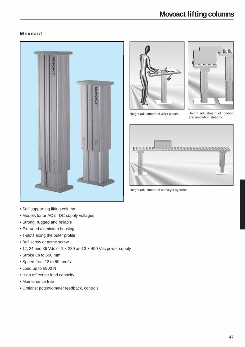
Movoact
• Self supporting lifting column
• Models for or AC or DC supply voltages
• Strong, rugged and reliable
• Extruded aluminium housing
• T-slots along the outer profi le
• Ball screw or acme screw
• 12, 24 and 36 Vdc or 1 × 230 and 3 × 400 Vac power supply
• Stroke up to 600 mm
• Speed from 12 to 60 mm/s
• Load up to 6800 N
• High off center load capacity
• Maintenance free
• Options: potentiometer feedback, controls.
Height adjustment of loading and unloading stations.
Height adjustment of conveyor systems.
Height adjustment of work places.

48
Movoact-DC
Available input voltages [Vdc] 12, 24 or 36
Available screw types Acme or Ball
Max. static load at fully retracted [N]
Acme screw models
Ball screw models
11 350
18 000
Min. / max. standard stroke [inch] 4 / 24
Duty cycle @ 25° C [%] 25
Temperature limits at operation [°C] - 25 to + 65
Max. end play [mm] 1
Wire cross section [mm2] 2,5
Wire length [mm] 2000
Connector included no
Technical data Features
• Rugged and robust
• Overload clutch (set to 1,2 – 1,5 × max. permissible load)
• Motor with auto reset thermal overload protection
• Accepts off center loads up to 700 Nm
• Acme or ball screw drive
• Holding brake prevents back driving on ball screw models
• Acme screw models are self-locking
• Safety nut on all ball screw models
• Can operate in a large temperature range
• Accepts large input voltage variations
• Maintenance free
• Potentiometer feedback
ModelMax.
dynamic
load [N]
Speed
@ min. load
[mm/s]
Speed
@ max. load
[mm/s]
DMD12–05A65 1100 54 32
DMD24–05A65 1100 54 32
DMD12–05B65 2250 61 37
DMD24–05B65 2250 61 37
DMD12–10A65 2250 30 18
DMD24–10A65 2250 30 18
DMD12–10B65 4500 30 19
DMD24–10B65 4500 30 19
DMD12–20A65 2250 15 12
DMD24–20A65 2250 15 12
DMD12–20B65 4500 15 12
DMD24–20B65 4500 15 12
DMD12–21B65 6800 15 11
DMD24–21B65 6800 15 11
Ordering
stroke
[inch]
Actual stroke
S
[mm]
4 102
6 152
8 203
10 254
12 305
14 356
16 406
18 457
20 508
24 610
Standard strokesPerformance table
Options

49
Ball screw driven models
Dimensions
Movoact-DC
Performance diagrams
Acme screw driven models
Speed and current
Off center load capacity

50
Movoact-AC
Available input voltages [Vac] 1 × 230 or 3 × 400
Input frequency [Hz] 50
Available screw types Acme or Ball
Max. static load at fully retracted [N]
Acme screw models
Ball screw models
11 350
18 000
Min. / max. standard stroke [inch] 4 / 24
Duty cycle @ 25° C [%] 25
Max. operation time [s] 45
Temperature limits at operation [°C] - 25 to + 65
Max. end play [mm] 1
Wire cross section [mm2] 2,5
Wire length [mm] 2000
Connector included no
Technical data Features
• Rugged and robust
• Overload clutch (set to 1,2 – 1,5 × max. permissible load)
• Motor with auto reset thermal overload protection
• Accepts off center loads up to 700 Nm
• Acme or ball screw drive
• Holding brake prevents back driving on ball screw models
• Acme screw models are self-locking
• Safety nut on all ball screw models
• Can operate in a large temperature range
• Accepts large input voltage variations
• Maintenance free
• Potentiometer feedback
Ordering
stroke
[inch]
Actual stroke
S
[mm]
4 102
6 152
8 203
10 254
12 305
14 356
16 406
18 457
20 508
24 610
Standard strokesPerformance table
ModelMax.
dynamic
load [N]
Speed
@ min. load
[mm/s]
Speed
@ max. load
[mm/s]
DMA22–05A65 1100 48 38
DMA22–05B65 2250 61 37
DMA42–05B65 2250 61 37
DMA22–10A65 2250 30 18
DMA42–10A65 2250 30 18
DMA22–10B65 4500 30 19
DMA42–10B65 4500 30 19
DMA22–20A65 2250 15 12
DMA42–20A65 2250 15 12
DMA22–20B65 4500 15 12
DMA42–20B65 4500 15 12
DMA22–21B65 6800 15 11
DMA42–21B65 6800 15 11
Options
51
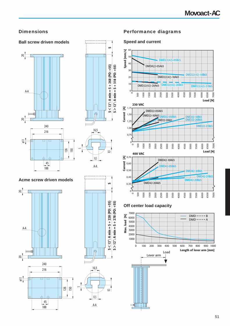
Ball screw driven models
Dimensions
Movoact-AC
Performance diagrams
Acme screw driven models
Speed and current
Off center load capacity
52
Ordering key
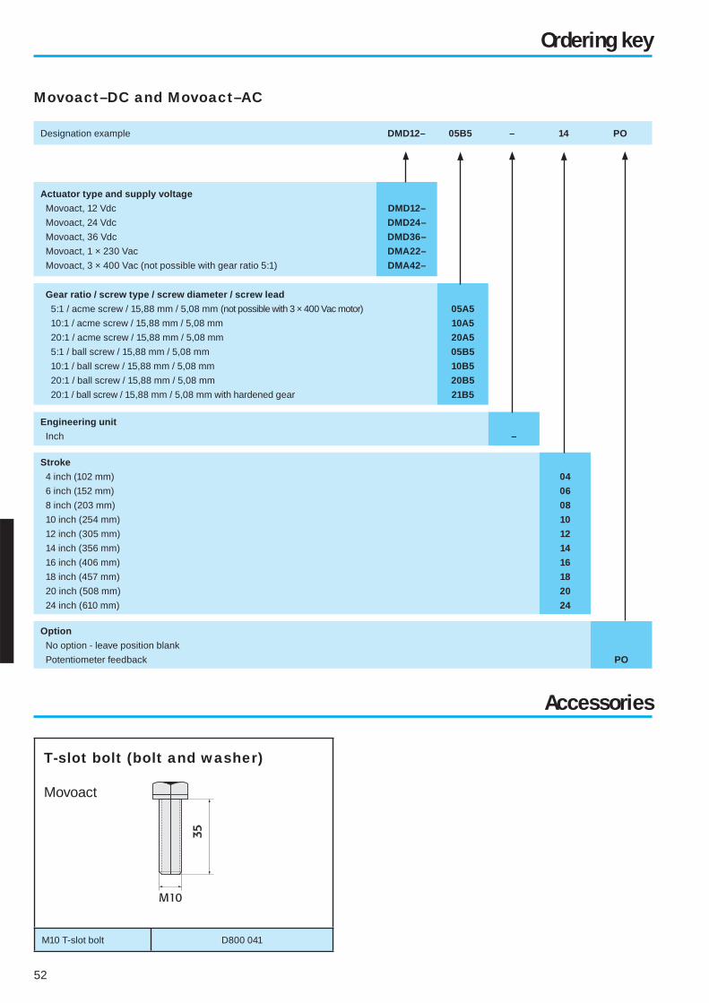
Movoact–DC and Movoact–AC
Designation example DMD12– 05B5 – 14 PO
Actuator type and supply voltage
Movoact, 12 Vdc
Movoact, 24 Vdc
Movoact, 36 Vdc
Movoact, 1 × 230 Vac
Movoact, 3 × 400 Vac (not possible with gear ratio 5:1)
DMD12–
DMD24–
DMD36–
DMA22–
DMA42–
Gear ratio / screw type / screw diameter / screw lead
5:1 / acme screw / 15,88 mm / 5,08 mm (not possible with 3 × 400 Vac motor)
10:1 / acme screw / 15,88 mm / 5,08 mm
20:1 / acme screw / 15,88 mm / 5,08 mm
5:1 / ball screw / 15,88 mm / 5,08 mm
10:1 / ball screw / 15,88 mm / 5,08 mm
20:1 / ball screw / 15,88 mm / 5,08 mm
20:1 / ball screw / 15,88 mm / 5,08 mm with hardened gear
05A5
10A5
20A5
05B5
10B5
20B5
21B5
Engineering unit
Inch –
Stroke
4 inch (102 mm)
6 inch (152 mm)
8 inch (203 mm)
10 inch (254 mm)
12 inch (305 mm)
14 inch (356 mm)
16 inch (406 mm)
18 inch (457 mm)
20 inch (508 mm)
24 inch (610 mm)
04
06
08
10
12
14
16
18
20
24
Option
No option - leave position blank
Potentiometer feedback PO
Accessories
M10 T-slot bolt D800 041
T-slot bolt (bolt and washer)
Movoact

53
LoadMaster 80 rodless actuator
LoadMaster 80
• Rodless actuator
• Two versions, for horizontal or vertical operation
• Rigid self supporting aluminium profi le
• Quiet operation for indoor domestic or medical use
• Trapezoidal or ball screw drive
• Spring loaded soft stop at end of stroke
• Stroke up to 1500 mm (longer possible upon request)
• Speed up to 110 mm/s
• Load up to 2000 N
• Options such as hand wind, spline safety function and
alternative motor positions.Handicap adaptation of vehicles
Lifting aids for disabled Patient lifts Loading an unloading stations

54
Forces Motor positions
LoadMaster 80 – version for vertical operation
Features
• Rodless actuator for vertical operation
• Durable, corrosion free and lightweight
• Stable self supporting extruded aluminium profi le
• Easy T-slot mounting
• Trapezoidal or ball screw drive
• Holds load at stand still (self locking)
• Spring loaded soft stop at end of stroke
• Safety nut on all ball screw models
• Motor with auto reset thermal overload protection
• Can operate in a large temperature range
• Accepts large input voltage variations
• IP44 (enclosed version) or IP33
• Maintenance free
• Hand wind
• Alternative motor position
• Spline safety function
Available input voltages [Vdc] 12, 24
Available screw types Trapezoidal or Ball
Max. load Fa [N]
DT • • – T68M • • • • • V(F)
DT • • – B61M • • • • • V(F)
DT • • – B62M • • • • • V(F)
DT • • – B65M • • • • • V(F)
650
1000
450
2000
Max. load torque Ma [Nm]
DT • • – T68M • • • • • V(F)
DT • • – B61M • • • • • V(F)
DT • • – B62M • • • • • V(F)
DT • • – B65M • • • • • V(F)
250
400
180
750
Min. / max. standard stroke [mm] 500 / 1500
Duty cycle @ 20° C [%] 15
Max. operation time [s] 120
Temperature limits at operation [°C] -0 to + 40
Protection degree
With motor enclosure
Without motor enclosure
IP44
IP33
Weight [kg] L × 5,7 + 2,8
Wire cross section [mm2] 1,5
Cable length [mm]
Models with motor enclosure
Models without motor enclosure
2000
cable clips on motor
Connector included
Models with motor enclosure
Models without motor enclosure
yes
no
Ma
Fa
Model
Maximum
load Fa
[N]
Speed
@ min. load
[mm/s]
Speed
@ max. load
[mm/s]
DT12–T68M • • • • • V(F) 650 44 29
DT24–T68M • • • • • V(F) 650 44 35
DT12–B61M • • • • • V(F) 1000 55 37
DT24–B61M • • • • • V(F) 1000 55 43
DT12–B62M • • • • • V(F) 450 110 67
DT24–B62M • • • • • V(F) 450 110 83
DT12–B65M • • • • • V(F) 2000 28 19
DT24–B65M • • • • • V(F) 2000 28 22
Performance table
Technical data
Ordering
stroke
[cm]
Actual stroke
S
[mm]
50 500
60 600
70 700
80 800
90 900
100 1000
110 1100
120 1200
130 1300
140 1400
150 1500
Standard strokes T-slot bolt kit
P/n D680 507
Options

55
Performance diagrams
DT • • – T68M • • • • • V(F) •
DT • • – B61M • • • • • V(F) •
DT • • – B62M • • • • • V(F) •
DT • • – B65M • • • • • V(F)
LoadMaster 80 – version for vertical operation
Dimensions
Model “A” “B”
DT • • – B65M • • • • • V • 53 97
DT • • – B62M • • • • • V • 53 120
DT • • – B61M • • • • • V • 53 120
DT • • – T68M • • • • • V • 50 88
Model “A” “B”
DT • • – B65M • • • • • F • 53 126
DT • • – B62M • • • • • F • 53 144
DT • • – B61M • • • • • F • 53 144
DT • • – T68M • • • • • F • 50 92
Vertical models

56
LoadMaster 80 – version for horizontal operation
Available input voltages [Vdc] 12, 24
Available screw types Trapezoidal or Ball
Max. load Fb [N] 2000
Max. load torque Mb [Nm]
DT • • – T68M • • • • • H
DT • • – B61M • • • • • H
DT • • – B62M • • • • • H
DT • • – B65M • • • • • H
250
400
180
750
Min. / max. standard stroke [mm] 500 / 1500
Duty cycle @ 20° C [%] 15
Max. operation time [s] 120
Temperature limits at operation [°C] -0 to + 40
Protection degree
With motor enclosure
Without motor enclosure
IP44
IP33
Weight [kg] L × 5,7 + 2,8
Wire cross section [mm2] 1,5
Cable length [mm]
Models with motor enclosure
Models without motor enclosure
2000
cable clips on motor
Connector included
Models with motor enclosure
Models without motor enclosure
yes
no
Technical data Features
• Rodless actuator for horizontal operation
• Durable, corrosion free and lightweight
• Stable self supporting extruded aluminium profi le
• Easy T-slot mounting
• Trapezoidal or ball screw drive
• Spring loaded soft stop at end of stroke
• Safety nut on all ball screw models
• Motor with auto reset thermal overload protection
• Can operate in a large temperature range
• Accepts large input voltage variations
• IP44 (enclosed version) or IP33
• Maintenance free
• Hand wind
• Alternative motor position
Model
Maximum
load Fb
[N]
Speed
@ min. load
[mm/s]
Speed
@ max. load
[mm/s]
DT12–T68M • • • • • H 2000 44 37
DT24–T68M • • • • • H 2000 44 37
DT12–B61M • • • • • H 2000 55 50
DT24–B61M • • • • • H 2000 55 50
DT12–B62M • • • • • H 2000 110 73
DT24–B62M • • • • • H 2000 110 87
DT12–B65M • • • • • H 2000 28 28
DT24–B65M • • • • • H 2000 28 28
Ordering
stroke
[cm]
Actual stroke
S
[mm]
50 500
60 600
70 700
80 800
90 900
100 1000
110 1100
120 1200
130 1300
140 1400
150 1500
Standard strokes T-slot bolt kitPerformance table
Mb
Fb
Forces Motor positions
P/n D680 507
Options

57
LoadMaster 80 – version for horizontal operation
Dimensions
Performance diagrams DT • • – T68M • • • • • H • DT • • – B61M • • • • • H •
DT • • – B62M • • • • • H • DT • • – B65M • • • • • H •
Horizontal models
Defl ection of profi le
Model “A” “B”
DT • • – B65M • • • • • H • 79,0 77,0
DT • • – B62M • • • • • H • 102,0 77,0
DT • • – B61M • • • • • H • 102,0 77,0
DT • • – T68M • • • • • H • 55,0 76,0
58
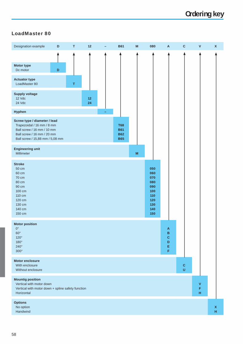
Designation example D T 12 – B61 M 080 A C V X
Motor type Dc motor D
Actuator type LoadMaster 80 T
Supply voltage 12 Vdc 24 Vdc
1224
Hyphen –
Screw type / diameter / lead Trapezoidal / 16 mm / 8 mm Ball screw / 16 mm / 10 mm Ball screw / 16 mm / 20 mm Ball screw / 15,88 mm / 5,08 mm
T68B61B62B65
Engineering unit Millimeter M
Stroke 50 cm 60 cm 70 cm 80 cm 90 cm 100 cm 110 cm 120 cm 130 cm 140 cm 150 cm
050060070080090100110120130140150
Motor position 0° 60° 120° 180° 240° 300°
ABCDEF
Motor enclosure With enclosure Without enclosure
CU
Mountig position Vertical with motor down Vertical with motor down + spline safety function Horizontal
VFH
Options No option Handwind
XH
Ordering key
LoadMaster 80

59
Controls
• Controls available for all actuator models
• Models for AC or DC power supply
• Versions with limit switch inputs
• Versions with electronic limit switches (ELS)
• Models with outputs for one or two actuators
• Hand controls available for most models
60
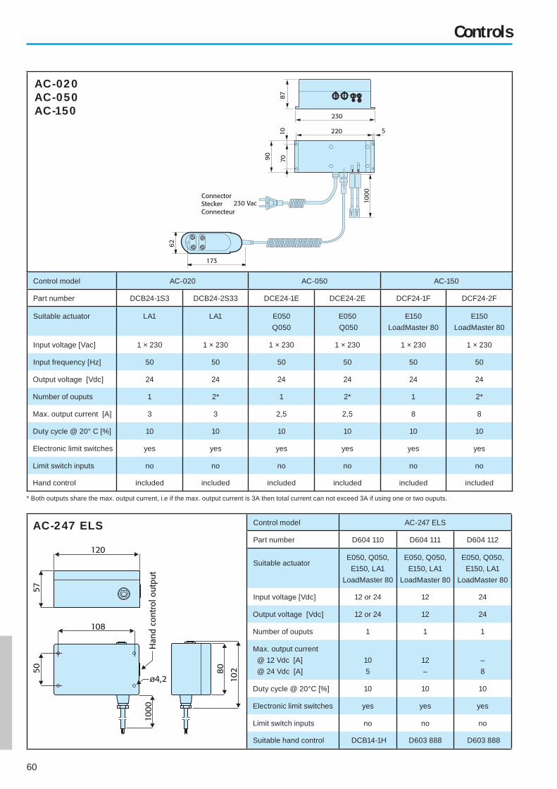
Control model AC-020 AC-050 AC-150
Part number DCB24-1S3 DCB24-2S33 DCE24-1E DCE24-2E DCF24-1F DCF24-2F
Suitable actuator LA1 LA1 E050
Q050
E050
Q050
E150
LoadMaster 80
E150
LoadMaster 80
Input voltage [Vac] 1 × 230 1 × 230 1 × 230 1 × 230 1 × 230 1 × 230
Input frequency [Hz] 50 50 50 50 50 50
Output voltage [Vdc] 24 24 24 24 24 24
Number of ouputs 1 2* 1 2* 1 2*
Max. output current [A] 3 3 2,5 2,5 8 8
Duty cycle @ 20° C [%] 10 10 10 10 10 10
Electronic limit switches yes yes yes yes yes yes
Limit switch inputs no no no no no no
Hand control included included included included included included
AC-020AC-050AC-150
Controls
Control model AC-247 ELS
Part number D604 110 D604 111 D604 112
Suitable actuatorE050, Q050,
E150, LA1
LoadMaster 80
E050, Q050,
E150, LA1
LoadMaster 80
E050, Q050,
E150, LA1
LoadMaster 80
Input voltage [Vdc] 12 or 24 12 24
Output voltage [Vdc] 12 or 24 12 24
Number of ouputs 1 1 1
Max. output current
@ 12 Vdc [A]
@ 24 Vdc [A]
10
5
12
–
–
8
Duty cycle @ 20°C [%] 10 10 10
Electronic limit switches yes yes yes
Limit switch inputs no no no
Suitable hand control DCB14-1H D603 888 D603 888
AC-247 ELS
* Both outputs share the max. output current, i.e if the max. output current is 3A then total current can not exceed 3A if using one or two ouputs.

61
Part number DCB14-1H D603 888
Suitable control D604 110 D604 111 / D604 112
Cable lenght [m] 850 ±50 850 ±50
Hand controls
Controls
Control model AC-063B
Part number DC24-1B DCA24-1B
Suitable actuator LA10
PPA-DC
Movoact
LA14
Input voltage [Vdc] 12 - 36 12 - 36
Output voltage [Vdc] 12 - 36 12 - 36
Number of ouputs 1 1
Max. output current
@ 12 Vdc [A]
@ 24 Vdc [A]
@ 36 Vdc [A]
30
17
12
30
17
12
Duty cycle @ 20° C [%] 10 10
Electronic limit switches no no
Limit switch inputs no yes*
Hand control* not included not included
AC-063B
Control model AC-063C
Part number DC24-1C DCA24-1C
Suitable actuator LA10
PPA-DC
Movoact
LA14
Input voltage [Vac] 1 × 230 1 × 230
Input frequency [Hz] 50 50
Output voltage [Vdc] 24 24
Number of ouputs 1 1
Max. output current [A] 17 17
Duty cycle @ 20° C [%] 10 10
Electronic limit switches no no
Limit switch inputs no yes*
Hand control included included
AC-063C
*Limit switches or sensors must be of type normally open.
*Suitable handcontrol DCB14-1H

62
– Page intentionally left blank –

63
– Page intentionally left blank –

64
ThomsonThomson Tollo
MicronDeltran PT
BRANDSFranceDanaher Motion S.A.S.C.P. 8001812, Rue Antoine Becquerel - Z.I. SudBâtiment Paul Tiger 2F-72026 Le Mans Cedex 2Tel. +33 (02) 43 50 03 30Fax. +33 (02) 43 50 03 39E-mail [email protected]
GermanyDanaher MotionPostfach 1153D-72645 WolfschlugenTel. +49 (0)180 5 24 67 90Fax. +49 (0)180 5 24 40 85E-mail [email protected]
SpainDanaher MotionTollo Linear SpainBadal, 29–31 7th, 1st08014 BarcelonaTel. +34 (0) 9329 80278Fax. +34 (0) 9329 80278E-mail [email protected]
Most products are available through authorised local distributors. Please visit our web site for further in for ma tion or contact your nearest offi ce. Dis tri bu tors are located in the following countries:
SwedenDanaher MotionTollo Linear ABBox 9053SE-291 09 KristianstadTel. +46 (0)44 24 67 00Fax. +46 (0)44 24 40 85E-mail [email protected]
United KingdomDanaher Motion Thomson IBL CompanyFishleigh RoadRoundswell Business Park Barnstaple, Devon EX31 3UDTel. +44 (0) 1271 334500Fax. +44 (0) 1271 334502E-mail [email protected]
U.S.A.Danaher Motion45 Hazelwood DriveAmherst, New YorkTel. +1-716-691-9100Fax. +1-716-691-9196E-mail [email protected]
NetherlandsNorwayPolandPortugalScotlandSingaporeSouth Africa
GermanyHong KongIndiaIrelandIsraelItalyJapan
SpainSwedenSwitzerlandThailandTaiwanTurkeyU.S.A.
AustraliaAustriaBelgiumDenmarkEnglandFinlandFrance
OFFICES
DISTRIBUTORS
Your distributor
DW110450gb-0410Tollo Linear AB © 2004 Printed in Sweden
www.LinearActuators.com