Embed Size (px)
Citation preview
98175000 REV. D
1302 WEST BEARDSLEY AVENUE • P.O. BOX 1127 • ELKHART IN 46515 • (574) 295-8330 • FAX (574) 293-9914
© 2014 ELKHART BRASS MFG. CO., INC.
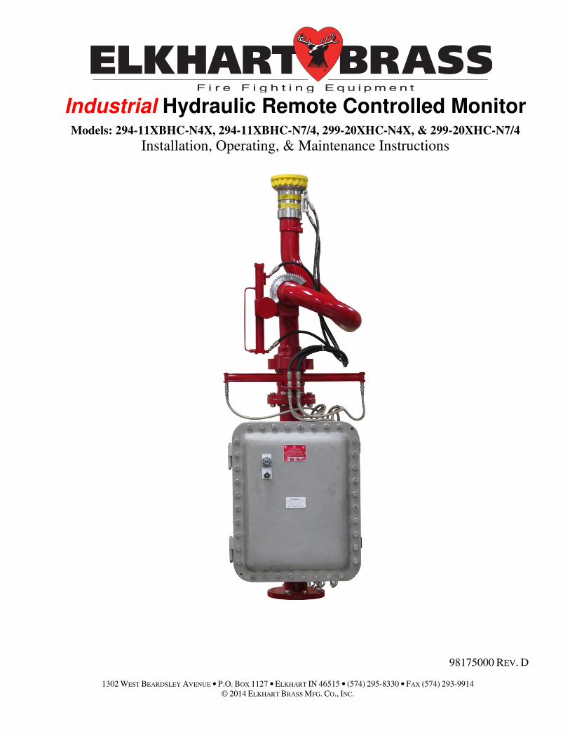
Industrial Hydraulic Remote Controlled Monitor Models: 294-11XBHC-N4X, 294-11XBHC-N7/4, 299-20XHC-N4X, & 299-20XHC-N7/4
Installation, Operating, & Maintenance Instructions

2
PRODUCT SAFETY
Important:
Before installing and operating this equipment, read & study this manual thoroughly. Proper installation is essential to safe operation. In addition, the following points should be adhered to in order to ensure the safety of equipment and personnel:
• All personnel who may be expected to operate this equipment must be thoroughly trained in its safe
and proper use.
• Before flowing water from this device, check that all personnel (fire service and civilian) are clear of
the stream path. Also confirm stream direction will not cause avoidable property damage.
• Become thoroughly familiar with the hydraulic characteristics of this equipment, and the pumping
system used to supply it. To produce effective fire streams, operating personnel must be properly
trained.
• Whenever possible, this equipment should be operated from a remote location to avoid exposing
personnel to dangerous fire conditions.
• Always open and close valves supplying this equipment slowly, so that the piping fills with water
slowly, thus preventing the possible occurrence of water hammer.
• After each use, and on a scheduled basis, inspect equipment per instructions in the maintenance section.
• Disconnect power prior to servicing controls.
• Any modifications to the electrical enclosure will destroy the NEMA 4 rating and void warranty
coverage of the enclosure and all components within.
• All equipment must be installed in accordance with local codes (NFPA 70 or EN/IEC 60079-14) as
appropriate and in areas where equipment classification is suitable.
WARNING: Do not attempt to disconnect or work on any electrical equipment in
this system unless power is removed or the area is known to be non-hazardous.
SYSTEM INFORMATION:
SERIAL NUMBER: ______________________________
DETAILS:
______________________________________________________________________________________
______________________________________________________________________________________
______________________________________________________________________________________
3
TABLE OF CONTENTS
I. OVERVIEW ------------------------------------------------------------------------------------------------ 4
II. SPECIFICATIONS --------------------------------------------------------------------------------------- 5
III. INSTALLATION INSTRUCTIONS ----------------------------------------------------------------- 6
A. Component Mounting - Monitor and Nozzle Installation ------------------------------------ 6
B. Interconnecting and Wiring Control System -------------------------------------------------- 8
C. Energize and adjust the hydraulic system ------------------------------------------------------ 8
D. Hydraulic pump pressure adjustment procedure ---------------------------------------------- 9
E. Adjusting speed of monitor and nozzle -------------------------------------------------------- 9
F. Manual Hydraulic Pump Installation Instruction --------------------------------------------- 13
IV. OPERATING INSTRUCTIONS --------------------------------------------------------------------- 14
A. Monitor control function operation ------------------------------------------------------------- 14
B. Automatic Horizontal Oscillation Operation (Optional) ------------------------------------ 15
C. Manual Hydraulic Pump Operation Instructions (Optional) ------------------------------- 16
V. MAINTENANCE --------------------------------------------------------------------------------------- 18
VI. TROUBLSHOOTING --------------------------------------------------------------------------------- 19
VII. MOUNTING DIMENSIONS AND REFERENCE DIAGRAMS ----------------------------- 22
VIII. SPARES ----------------------------------------------------------------------------------------------- 27
IX. ENGINEERING CHANGE REVISION EXPLANATIONS ------------------------------------ 28
4
I. OVERVIEW
Equipment
This Monitor, Nozzle, and Valve and Pump box is intended to be used in hazardous locations.
Depending on the configuration ordered it may be suitable for NFPA 70 class 1, Division 1 locations
and the compliance with local codes and company policies are required to maintain that area
classification.
The equipment is hydraulically actuated by a self-contained hydraulic pump that is enclosed within
the valve and pump box. All controls to the monitor are via hydraulic means and only control signals
are electrical. Power for an entire monitor is typically all sourced from the valve and pump box
connections except by special order in the case of remote/auxiliary control panels and RF controls.
Controls
Control switches are provided by push button or turn switches for:
• Power on/off
• Up
• Down
• Left
• Right
• Straight Stream
• Wide Fog
• Water on/off (if ordered as option)
• Foam on/off (if ordered as option)
• Oscillate on/off (if ordered as option)
Control voltages are typically 24VDC and share the same 24VDC power source as the hydraulic
pump.
An auxiliary control panel can be supplied.
Construction
The monitor is constructed of marine brass (85 Brass) and an option for Stainless Steel is available
for the 299-20 model.
The Valve and pump box is mounted on a steel riser spool and is a NEMA 7/4 enclosure constructed
of heavy cast aluminum and meets NFPA 70 / NEC article 505-Class 1, Division 1 requirements.
General
While the equipment is designed for long service, regular maintenance is required to insure that these
long life goals are achieved and your equipment is available for use when needed. Reduced
maintenance schedules have been shown to significantly reduce equipment life and serviceability.
5
II. SPECIFICATIONS
General Specifications
• Input Power (Automatic Wide Range Power Supply)
Voltage 85-264 VAC, 50/60 Hz., 1 Phase
Max Current 7.0 Amp
Other power supplies available by special order
• Monitor and Valve & Pump Box approximate Dimensions (W x H x D)
294-11XBHC w/Oscillation 25(635) x 82(2090) x 30(765)
294-11XBHC w/o Oscillation 25(635) x 76(2000) x 30(765)
299-20XHC w/ Oscillation 25(635) x 95(2325) x 30(765)
299-20XHC w/o Oscillation 25(635) x 89(2260) x 30(765)
• Monitor and Valve & Pump Box Weight
294-11XBHC 650 lbs.
299-20XHC 650 lbs.
• Operating Temperature range
Monitors have been installed in a wide variety of climates ranging from equatorial locations to
northern Europe. Due to the nature of the design with hydraulic controls, the forces available
generally exceed operational requirements. However, it should be noted that at extremely low
temperatures the viscosity of the oil will become thicker and movement rates will slow down. At
such time as water begins to flow, and from general use, the monitor will be warmed by the water
flowing to above freezing temperatures and the functions will approach room temperature
operation.
At extremely low temperatures the operation will be limited by the viscosity of the oil and
lubricating grease used. We estimate a practical limitation to be at -20°F but satisfactory
operation may be achieved below that temperature.
6
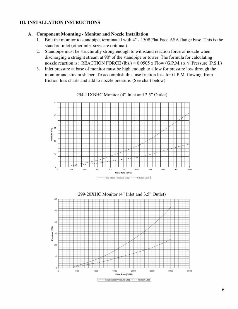
III. INSTALLATION INSTRUCTIONS
A. Component Mounting - Monitor and Nozzle Installation
1. Bolt the monitor to standpipe, terminated with 4" - 150# Flat Face ASA flange base. This is the
standard inlet (other inlet sizes are optional).
2. Standpipe must be structurally strong enough to withstand reaction force of nozzle when
discharging a straight stream at 90º of the standpipe or tower. The formula for calculating
nozzle reaction is: REACTION FORCE (lbs.) = 0.0505 x Flow (G.P.M.) x √¯ Pressure (P.S.I.)
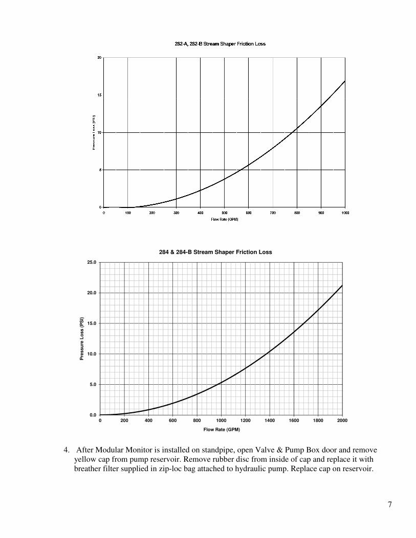
3. Inlet pressure at base of monitor must be high enough to allow for pressure loss through the
monitor and stream shaper. To accomplish this, use friction loss for G.P.M. flowing, from
friction loss charts and add to nozzle pressure. (See chart below).
294-11XBHC Monitor (4” Inlet and 2.5” Outlet)
299-20XHC Monitor (4” Inlet and 3.5” Outlet)
7
4. After Modular Monitor is installed on standpipe, open Valve & Pump Box door and remove
yellow cap from pump reservoir. Remove rubber disc from inside of cap and replace it with
breather filter supplied in zip-loc bag attached to hydraulic pump. Replace cap on reservoir.
0.0
5.0
10.0
15.0
20.0
25.0
0 200 400 600 800 1000 1200 1400 1600 1800 2000
Pre
ssu
re L
oss (
PS
I)
Flow Rate (GPM)
284 & 284-B Stream Shaper Friction Loss
8
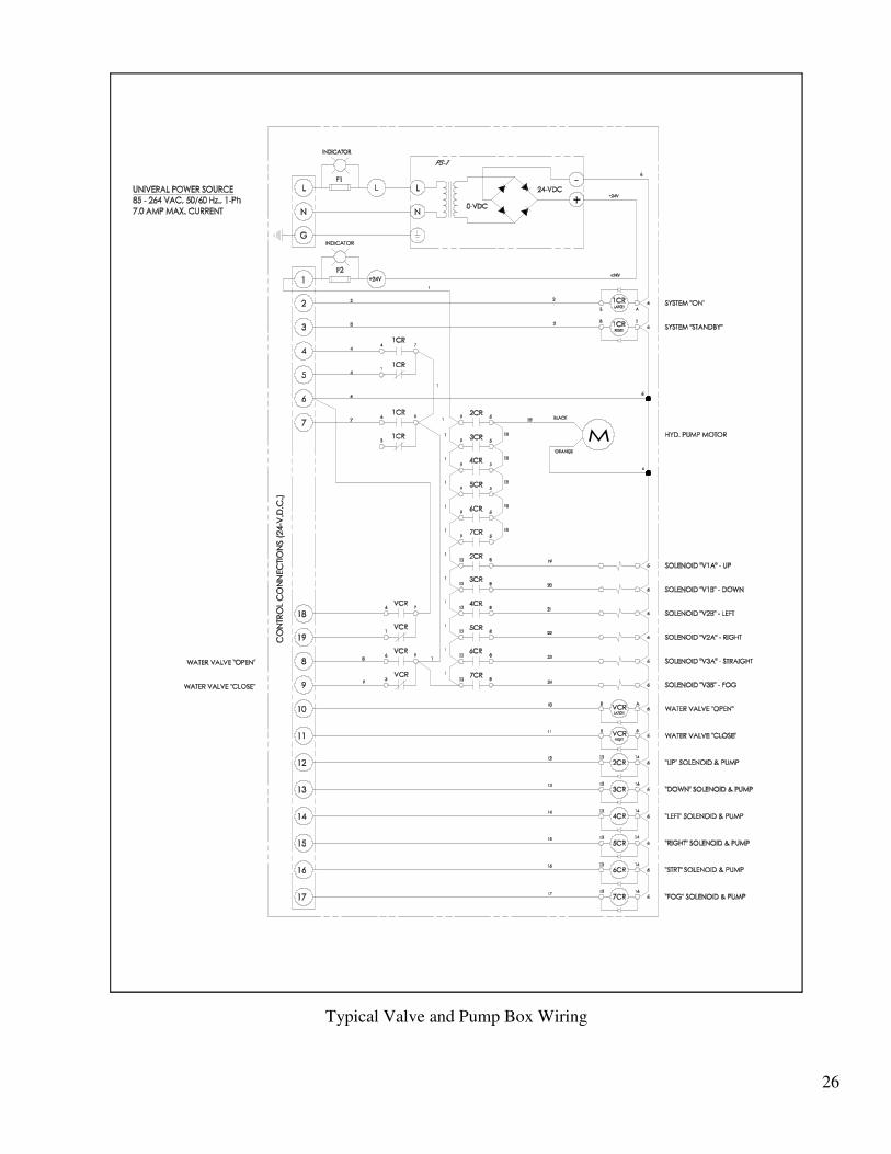
B. Interconnecting and Wiring Control System
1. Install control boxes at designated locations and cut out holes in box to attach conduit. All
cable entry knockouts on all NEMA #4X enclosures are provided by others. All NEMA #7/4
enclosures have N.P.T. female threaded entries provided.
2. Install conduit and pull electrical conductors between control boxes and Valve & Pump Box.
Main power source to be connected at Valve & Pump Box, supplied by others. Primary power
source required is: 85-265 VAC, 47-264 Hz., single-phase power. When power is connected,
ACDC power supplies will automatically set at voltage and cycles within range required. All
operating voltages for control system and hydraulic pump is 24-VDC powered through power
supply located in Valve & Pump Box. 15 conductors are required from each valve & pump box
to control box, see electrical drawings for connections.
3. Conductor size is determined by length of wire needed between control boxes. Recommended
conductor size is as follows:
0 – 300 foot length use #22 AWG wire (voltage drop = 0.48 maximum)
301 – 500 foot length use #20 AWG wire (voltage drop = 0.52 maximum)
501 – 800 foot length use #18 AWG wire (voltage drop = 0.52 maximum)
801 – 1200 foot length use #16 AWG wire (voltage drop = 0.51 maximum)
1201 – 1800 foot length use #14 AWG wire (voltage drop=0.49 maximum)
1801 – 3000 foot length use #12 AWG wire (voltage drop = 0.51 maximum)
WARNING: Make sure panels are grounded according to area classification and
company policy to assure panel code compliance.
C. Energize and adjust the hydraulic system
1. Fill reservoir with hydraulic fluid. For best results use automatic transmission fluid (Dexron III
or Chevron MD-3). Check reservoir fluid after each function is bled out.
WARNING!! Do not operate hydraulic pump without hydraulic fluid to avoid pump damage.
2. Priming hydraulic pump:
3. Remove electrical plug from valve solenoid V1B and hydraulic pressure tube between pump &
solenoid valve manifold.
4. Jog “UP” switch on control panel until hydraulic fluid flows out pressure port of pump.
5. Reconnect pressure hydraulic tube and valve solenoid electrical plug.
6. Bleed air out of system by using the following procedure:
a) Set pump relief valve pressure to 50 P.S.I., which is as low as possible. Lower monitor
vertical movement to maximum down position and disconnect hydraulic hoses from
vertical actuator ports V1A & VIB. Open port controls at both ends of rotary actuator; turn
screws counterclockwise until it stops. (See illustration 1 for location of port control valve
adjusting screws).
b) Insert open end of V1B hydraulic hose into clean container, and activate “UP” mode
switch at control box. Hold switch until hydraulic fluid is discharging from hose and is free
of air. Reconnect hydraulic hose to port V1B, increase pump pressure then, activate “UP”
switch until monitor rises to maximum elevation.
9
c) Close port controls valves at V1A & V1B actuator ports, turn screws clockwise until it
stops, and then open both screws one complete revolution.
d) Insert open end of V1A hydraulic hose into clean container, and activate “DOWN” mode
switch at control box. Hold switch until hydraulic fluid is discharging from hose and is free
of air. Reconnect hydraulic hose to port V1A, then activate “DOWN” switch until monitor
is lowered to minimum elevation.
e) Disconnect hydraulic lines from horizontal actuator ports V2A & V2B. Open port control
valves at both ends of rotary actuator, turn screws counterclockwise until they stop. (See
illustrations 1 & 4 for location). Manually turn monitor to maximum horizontal clockwise
position.
f) Insert open end of V2A hydraulic hose into clean container, and activate “LEFT” mode
switch at control box. Hold switch until hydraulic fluid is discharging from hose and is free
of air. Reconnect hydraulic hose to actuator port V2A, then activate “LEFT” switch until
monitor reaches maximum counterclockwise position.
g) Insert open end of V2B hydraulic hose into clean container, and activate “RIGHT” mode
switch at control box. Hold switch until hydraulic fluid is discharging from hose and is free
of air. Reconnect hydraulic hose to actuator port V2B, then activate “RIGHT” switch until
monitor is moved to maximum clockwise position.
h) Reposition monitor so nozzle hydraulic line connections are easily accessible. Disconnect
hydraulic lines V3A & V3B from nozzle ports. Open needle valve on nozzle (see
illustration 2) to full counterclockwise position. Then manually push nozzle tip to full fog
position. Insert open end of V3A hydraulic hose into clean container and activate “STRT”
switch at control box. Hold switch until fluid is discharging from hose and is free of air.
Reconnect hydraulic hose to nozzle port V3A and activate “STRT” switch until nozzle
reaches the straight stream position.
i) Insert open end of V3B hydraulic hose into clean container and activate “FOG” switch at
control box. Hold switch until fluid is discharging from hose and is free of air. Reconnect
hydraulic hose to nozzle port V3B and activate “FOG” switch until nozzle reaches the
maximum fog position. Lower monitor to approximately 45º below horizontal and move
from fog to straight stream positions several times allowing about one minute idle time at
each end of stroke, this will remove any remaining air bubbles in nozzle cylinder.
D. Hydraulic pump pressure adjustment procedure
1. Check hydraulic fluid levels in reservoir, if low add fluid.
2. Activate and hold “FOG” function switch, this will start hydraulic pump and move tip to fog
position. Hold switch in fog position and check pressure on gauge located in valve & pump
box.
3. Open adjustable relief valve until pressure reads 1000 PSI, and then tighten down lock nut on
relief valve screw. Turn relief valve screw clockwise to increase pressure and counter
clockwise to decrease pressure.
E. Adjusting speed of monitor and nozzle
1. Port control valves are located at each end of the monitor rotary actuators and needle valve is
plumbed into hydraulic line of piston on nozzle. (See illustrations on page 5).
2. Horizontal movement should operate at proper speed with port control valves at full open
(counter-clockwise) position.
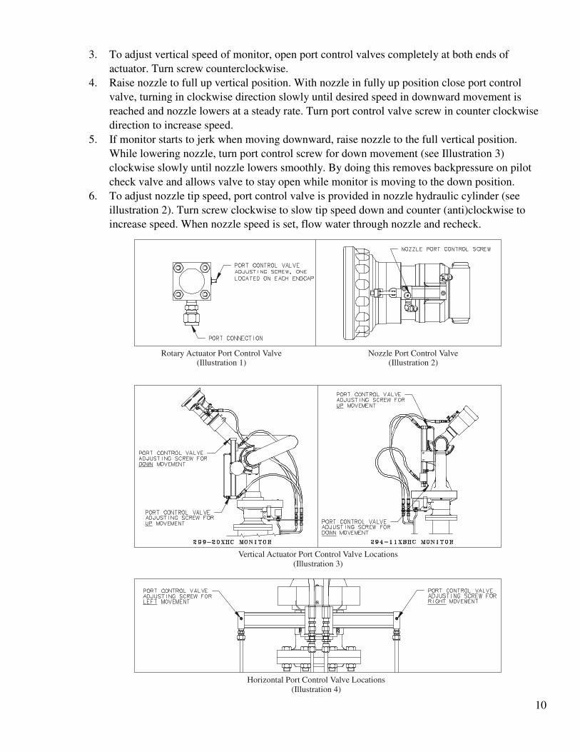
10
3. To adjust vertical speed of monitor, open port control valves completely at both ends of
actuator. Turn screw counterclockwise.
4. Raise nozzle to full up vertical position. With nozzle in fully up position close port control
valve, turning in clockwise direction slowly until desired speed in downward movement is
reached and nozzle lowers at a steady rate. Turn port control valve screw in counter clockwise
direction to increase speed.
5. If monitor starts to jerk when moving downward, raise nozzle to the full vertical position.
While lowering nozzle, turn port control screw for down movement (see Illustration 3)
clockwise slowly until nozzle lowers smoothly. By doing this removes backpressure on pilot
check valve and allows valve to stay open while monitor is moving to the down position.
6. To adjust nozzle tip speed, port control valve is provided in nozzle hydraulic cylinder (see
illustration 2). Turn screw clockwise to slow tip speed down and counter (anti)clockwise to
increase speed. When nozzle speed is set, flow water through nozzle and recheck.
Rotary Actuator Port Control Valve(Illustration 1)
Nozzle Port Control Valve(Illustration 2)
Vertical Actuator Port Control Valve Locations(Illustration 3)
Horizontal Port Control Valve Locations(Illustration 4)
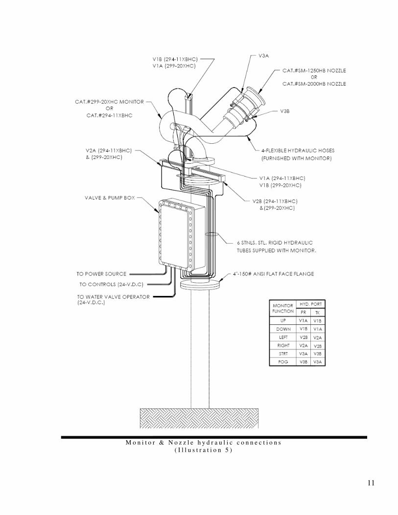
11
M o n i t o r & N o z z l e h y d r a u l i c c o n n e c t i o n s
( I l l u s t r a t i o n 5 )
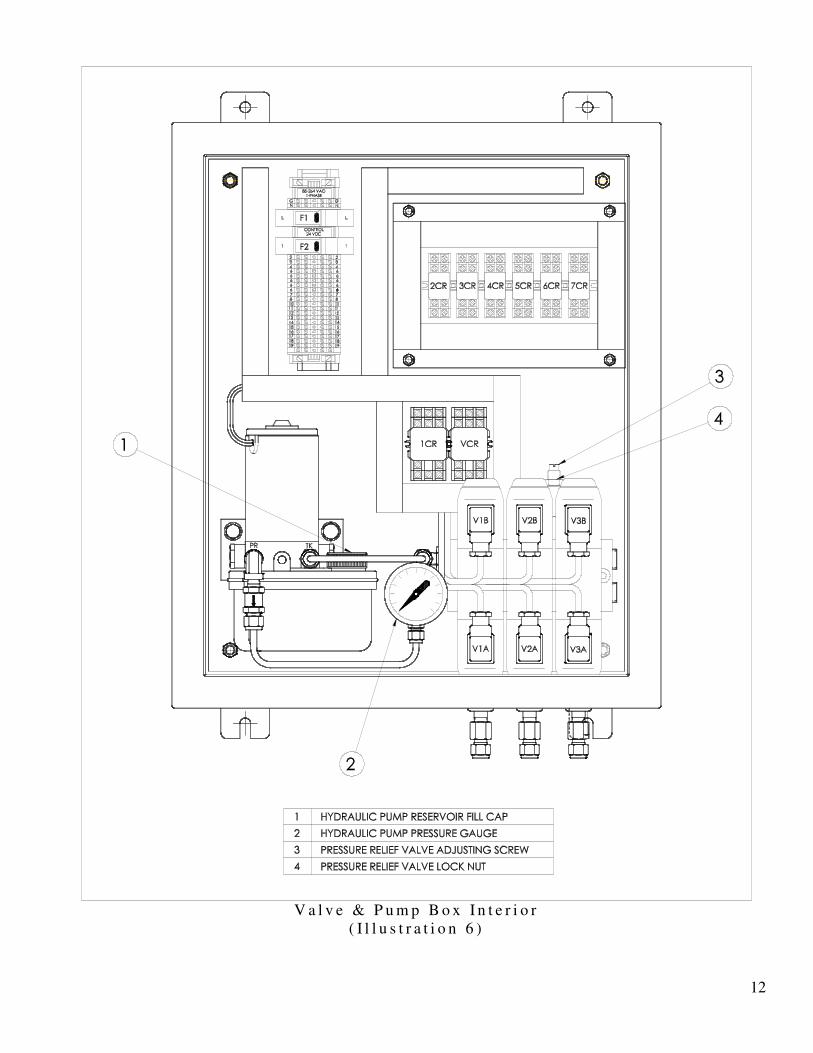
12
V a l v e & P u m p B o x I n t e r i o r
( I l l u s t r a t i o n 6 )
13
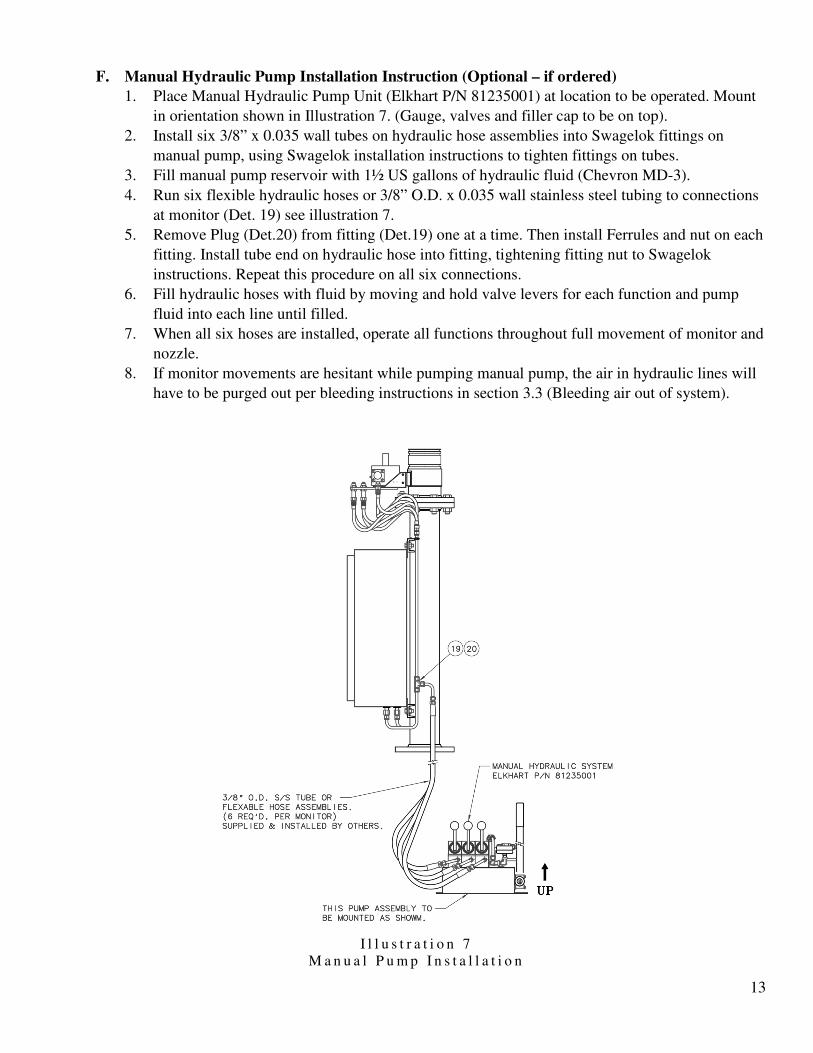
F. Manual Hydraulic Pump Installation Instruction (Optional – if ordered)
1. Place Manual Hydraulic Pump Unit (Elkhart P/N 81235001) at location to be operated. Mount
in orientation shown in Illustration 7. (Gauge, valves and filler cap to be on top).
2. Install six 3/8” x 0.035 wall tubes on hydraulic hose assemblies into Swagelok fittings on
manual pump, using Swagelok installation instructions to tighten fittings on tubes.
3. Fill manual pump reservoir with 1½ US gallons of hydraulic fluid (Chevron MD-3).
4. Run six flexible hydraulic hoses or 3/8” O.D. x 0.035 wall stainless steel tubing to connections
at monitor (Det. 19) see illustration 7.
5. Remove Plug (Det.20) from fitting (Det.19) one at a time. Then install Ferrules and nut on each
fitting. Install tube end on hydraulic hose into fitting, tightening fitting nut to Swagelok
instructions. Repeat this procedure on all six connections.
6. Fill hydraulic hoses with fluid by moving and hold valve levers for each function and pump
fluid into each line until filled.
7. When all six hoses are installed, operate all functions throughout full movement of monitor and
nozzle.
8. If monitor movements are hesitant while pumping manual pump, the air in hydraulic lines will
have to be purged out per bleeding instructions in section 3.3 (Bleeding air out of system).
I l l u s t r a t i o n 7
M a n u a l P u m p I n s t a l l a t i o n
14
IV. OPERATING INSTRUCTIONS
A. Monitor control function operation
1. Manual control operation:
a) “SYSTEM ON” push button switch will turn on power to all control circuits and can be
activated at any control box. This will enable all monitor controls.
b) “SYSTEM STANDBY” push button switch will disconnect power from all monitor
functions at any control panel.
c) Water valve “OPEN” & “CLOSE” push button switches are momentary contact
switches that operate a latching relay in Valve & Pump Box. Control power has to be on
for either one of these functions to switch. If power is lost on monitor, valve will maintain
last position set.
d) Monitor “LEFT” & “RIGHT” switch controls horizontal position of monitor & nozzle.
Hold switch in direction desired, until nozzle discharge position is reached. Then release
switch to stop movement.
e) Monitor “UP” & “DOWN” switch controls vertical movement of monitor & nozzle.
Hold switch in direction of vertical movement required, until nozzle discharge position is
reached, then release switch to stop.
f) Nozzle “STRT” & “FOG” switch controls stream pattern of nozzle and will adjust from
straight stream to wide fog. Tip movement can be stopped at any position by releasing
switch.
g) Note: On NEMA #4X control boxes “UP”, “DOWN”, “LEFT”, & “RIGHT” functions
are combined into one switch (4 way joystick switch).
2. Monitor control panel pilot lights:
a) “POWER ON” pilot light is located on each control panel. This indicates 24 Volts D.C.
control power is available at each Valve & Pump Box.
b) WATER VALVE “OPEN” pilot light indicates that water valve relay located in the Valve
& Pump Box is switched to the “open” position.
c) Horizontal “OSCILLATION” switch (Optional) controls Horizontal Oscillation mode,
automatic or manual.
15
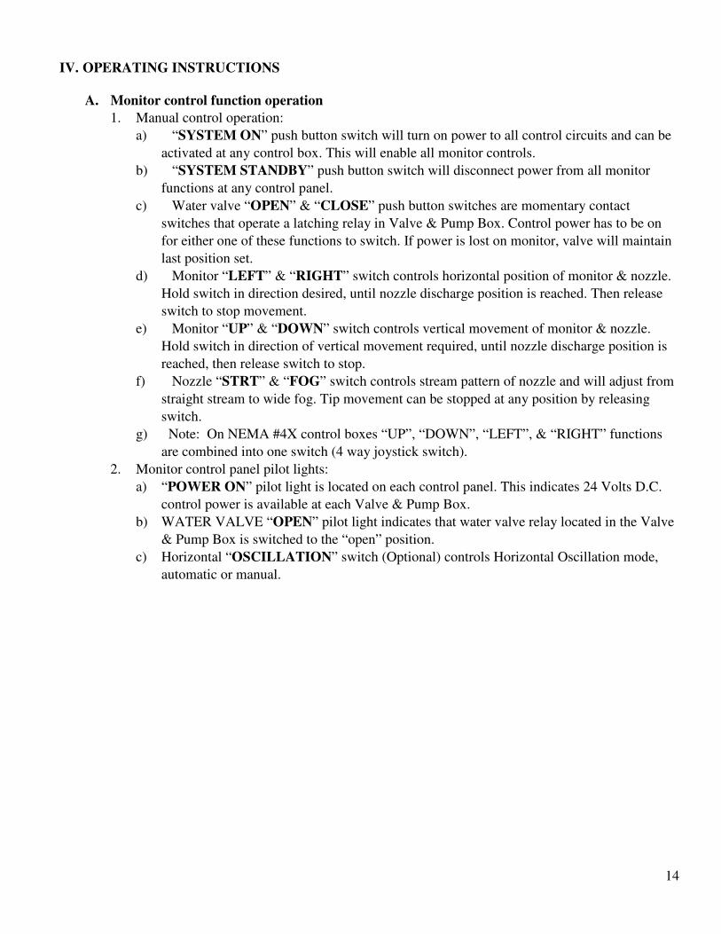
B. Automatic Horizontal Oscillation Operation (Optional)
1. Horizontal sweep switch will activate either automatic or manual horizontal sweep. The
position of switch will be indicated by pilot lights on control box, either “manual” or
“Automatic”. When in “AUTO” mode, monitor will automatically oscillate horizontal
movement within the perimeters of the limit switches that are mounted on the horizontal
actuator. Loosening set screws on reed switch brackets and moving them along cylinder until
desired oscillation pattern is reached can change these perimeters. Then tighten set screws to
lock switch into place (see illustration 8).
Horizontal Actuator with Limit Switches Installed
(Illustration 8)
16
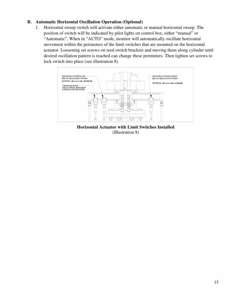
C. Manual Hydraulic Pump Operation Instructions (OPTIONAL)
1. The hydraulic manual pump (Illustration 9) has 3 directional valves with levers. There is one
hand pump with handle
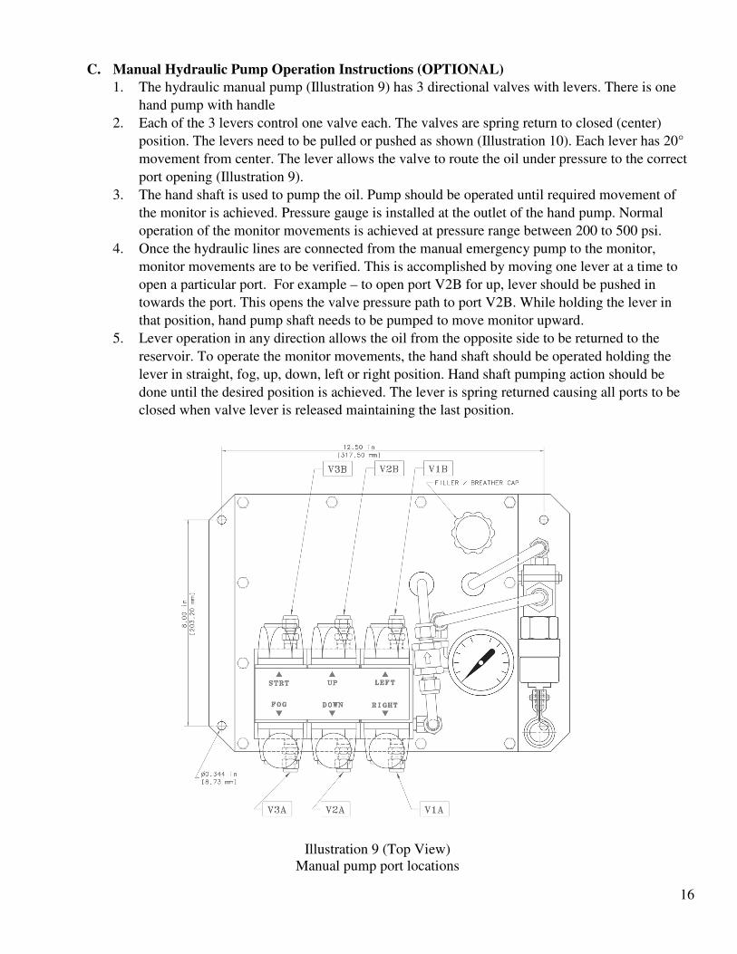
2. Each of the 3 levers control one valve each. The valves are spring return to closed (center)
position. The levers need to be pulled or pushed as shown (Illustration 10). Each lever has 20°
movement from center. The lever allows the valve to route the oil under pressure to the correct
port opening (Illustration 9).
3. The hand shaft is used to pump the oil. Pump should be operated until required movement of
the monitor is achieved. Pressure gauge is installed at the outlet of the hand pump. Normal
operation of the monitor movements is achieved at pressure range between 200 to 500 psi.
4. Once the hydraulic lines are connected from the manual emergency pump to the monitor,
monitor movements are to be verified. This is accomplished by moving one lever at a time to
open a particular port. For example – to open port V2B for up, lever should be pushed in
towards the port. This opens the valve pressure path to port V2B. While holding the lever in
that position, hand pump shaft needs to be pumped to move monitor upward.
5. Lever operation in any direction allows the oil from the opposite side to be returned to the
reservoir. To operate the monitor movements, the hand shaft should be operated holding the
lever in straight, fog, up, down, left or right position. Hand shaft pumping action should be
done until the desired position is achieved. The lever is spring returned causing all ports to be
closed when valve lever is released maintaining the last position.
Illustration 9 (Top View)
Manual pump port locations
17
Illustration 10 (Right View)
Lever movement of the 4-way directional valves
18
V. MAINTENANCE INSTRUCTIONS
A. Monthly inspection and maintenance:
1. Check all indicator lights and replace bulbs if not operating correctly.
2. Check hydraulic pump reservoir for fluid level.
3. Operate all functions on system to insure proper working condition.
4. Operate all monitor and nozzle functions several times, to activate solenoid valves in
Valve & Pump Box. This will clean any residue from spools and keep them from
sticking.
B. Six month inspection and maintenance:
1. Grease monitor ball races through grease fittings located at each swivel joint. Use a good
grade waterproof lithium grease.
2. Check flexible hydraulic hoses at monitor for cracks and deterioration.
3. Check all hydraulic connections at rigid lines and in valve & pump box for leaks. Repair
as needed.
4. Check all painted surfaces for chips or scratches and repaint as required.
5. Visually check all electrical equipment in control boxes and valve & pump boxes.
C. Refer to individual manuals for valves, nozzles, and any other associated equipment for their
individual maintenance requirements.
19
VI. TROUBLESHOOTING
A. Electrical Checks
1. Is the problem isolated to a particular function (Left/Right, Up/Down, Straight/Fog)
2. If the problem is repeatedly only on a particular function it indicates that the issue is less likely to
be hydraulic and more likely to be with the electrical controls or connections.
3. Even if it is isolated to one particular function it is still possible to be a hydraulic issue.
4. Verify that all terminal screws for both internal and external functions are tight.
5. Frequently interconnection wires do not get tightened at the job site.
6. Sometimes the wires work loose from shipping and handling.
7. Proper torque should be 4.5 – 7.1 in-lbs. (0.508 – 0.802 Nm).
8. Confirm solenoid operation by sound or feel while operating it from the controls.
a) Functions are as follows:
(1) 2CR –Up
(2) 3CR –Down
(3) 4CR –Left
(4) 5CR –Right
(5) 6CR – Nozzle Straight Stream
(6) 7CR – Nozzle Wide Fog
b) If exchanging these relays causes the problem to move from one function to another this
indicates that the relay is not operating correctly.
9. Verify the response of the Valve & Pump box (V&P) to input signals.
a) The system operates on 24 VDC signals.
b) Terminal assignments are as follows:
(1) 1 – 24 VDC
(2) 10 – Water valve open (CAUTION, Read Below)
(a) Terminal 10 will open the water valve if it is powered. This could pose a physical
hazard to others.
(3) 11 – Water valve closed
(4) 12 – Up
(5) 13 – Down
(6) 14 – Left
(7) 15 – Right
(8) 16 – Straight
(9) 17 – Fog
c) A piece of jumper wire can be used to apply those signals for testing. A 24VDC source can
be used from terminal 1 to the terminal of the function being tested.
CAUTION – There are some things to be careful of in performing this test.
(1) Never come into contact with terminals labeled L, L1, L2, or L3 or similar as these
carry the mains voltage and are extremely dangerous.
(2) Mains voltage is present at the terminals of the power switch. Do not touch them.
d) Does the monitor respond correctly to the input signals?
(1) Does the hydraulic pressure rise to approximately 1000 PSI on pressure gauge when
function is activated against the end of stroke?
(a) This indicates that the pump is operating correctly.
(b) See manual for regulator adjusting procedures.
e) Verify that the pump stops when the signal is removed.
(1) Does the hydraulic pressure drop to 0-25 PSI on pressure gauge when function is
released?
20
10. Is the correct signal being sent to the Valve & Pump box from the control panel?
a) Verify that for each function there is the appropriate 24 VDC signal at the correct terminal.
b) The signal must be constant and not intermittent when applied.
c) Terminal assignments for operation are listed above.
B. Hydraulic checks
1. Verify the oil level in the reservoir
a) It should be between the Max and Min marks on the side of the reservoir
(1) If the oil level becomes too low it will allow air to be introduced into the system
causing functional problems. From a practical perspective the oil pump intake will not
be uncovered until the oil is below approximately 0.5 inches (13 mm), but we do not
recommend operation below the minimum level.
b) If the oil level is low it will be necessary to determine if there is a leak.
(1) Does oil repeatedly need to be added to maintain the level?
(2) Is the leak inside the panel, or outside? Similar detection techniques apply and are
described below.
2. If the oil level is very low, or if air leakage into the system is suspected, it will be necessary to
bleed the hydraulics (horizontal, vertical and nozzle) according to the manual.
a) Indications of air in the system are:
(1) Erratic or no operation even though the relays are energizing properly
(2) The monitor position is not rigid and can be moved manually by grasping the nozzle
and pulling the monitor left/right or up/down.
3. Is there oil in the bottom of the enclosure:
a) How much oil is present?
(1) The reservoir can allow for a significant amount of oil to be lost and still operate.
b) What area (location) in the enclosure is the oil observed?
(1) The location the oil first strikes the bottom indicates where it is dripping from. This
may or may not be directly from the leak but helps to locate it and define what is not
leaking.
c) Can a source be located? It may help to:
(1) Use a clean tissue to wipe around each fitting. The leaking one should show a red oily
residue on the tissue. Fittings below the leaking one may also show the same residue
due to the leak above.
(2) Wipe up the oil in the cabinet.
(3) Place a white paper or a rag on the bottom of the enclosure.
(4) Wrap tissue around suspect fittings.
(5) Close the panel and operate the monitors and nozzles periodically looking for leaks.
(6) This will apply pressure to the hydraulics.
(7) The leak may be insufficient to present itself immediately.
(8) Check back later (maybe even the next day) to see if a leak has occurred or if a source
can be located.
(9) Periodic operation will help to insure the leak occurs.
(10) If a fitting connection is leaking it is possible to tighten it up, but proceed with caution
as it is also possible to over tighten them. No more than 1/8 turn should be required
(probably much less) unless they are only finger tight. Fittings are tightened up
according to dimension and not by torque. Detailed procedure can be found at
http://www.swagelok.com/downloads/webcatalogs/EN/MS-13-151.PDF.
(11) A similar process to that described in the steps above can be used on external
connections as well.
21
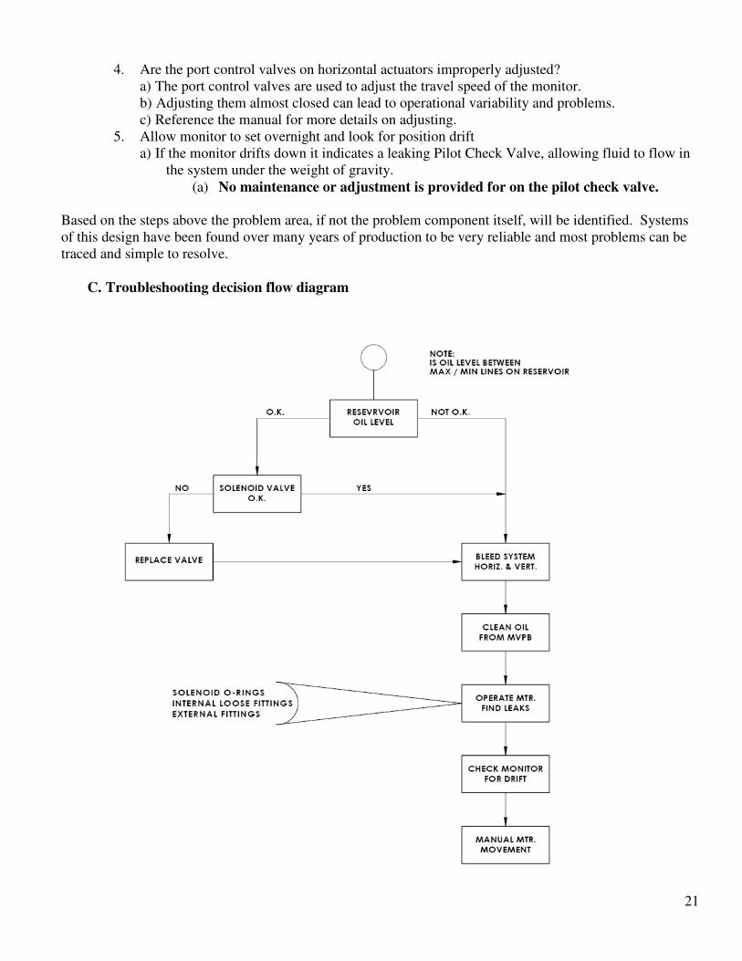
4. Are the port control valves on horizontal actuators improperly adjusted?
a) The port control valves are used to adjust the travel speed of the monitor.
b) Adjusting them almost closed can lead to operational variability and problems.
c) Reference the manual for more details on adjusting.
5. Allow monitor to set overnight and look for position drift
a) If the monitor drifts down it indicates a leaking Pilot Check Valve, allowing fluid to flow in
the system under the weight of gravity.
(a) No maintenance or adjustment is provided for on the pilot check valve.
Based on the steps above the problem area, if not the problem component itself, will be identified. Systems
of this design have been found over many years of production to be very reliable and most problems can be
traced and simple to resolve.
C. Troubleshooting decision flow diagram
22
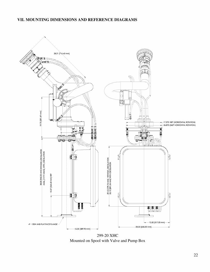
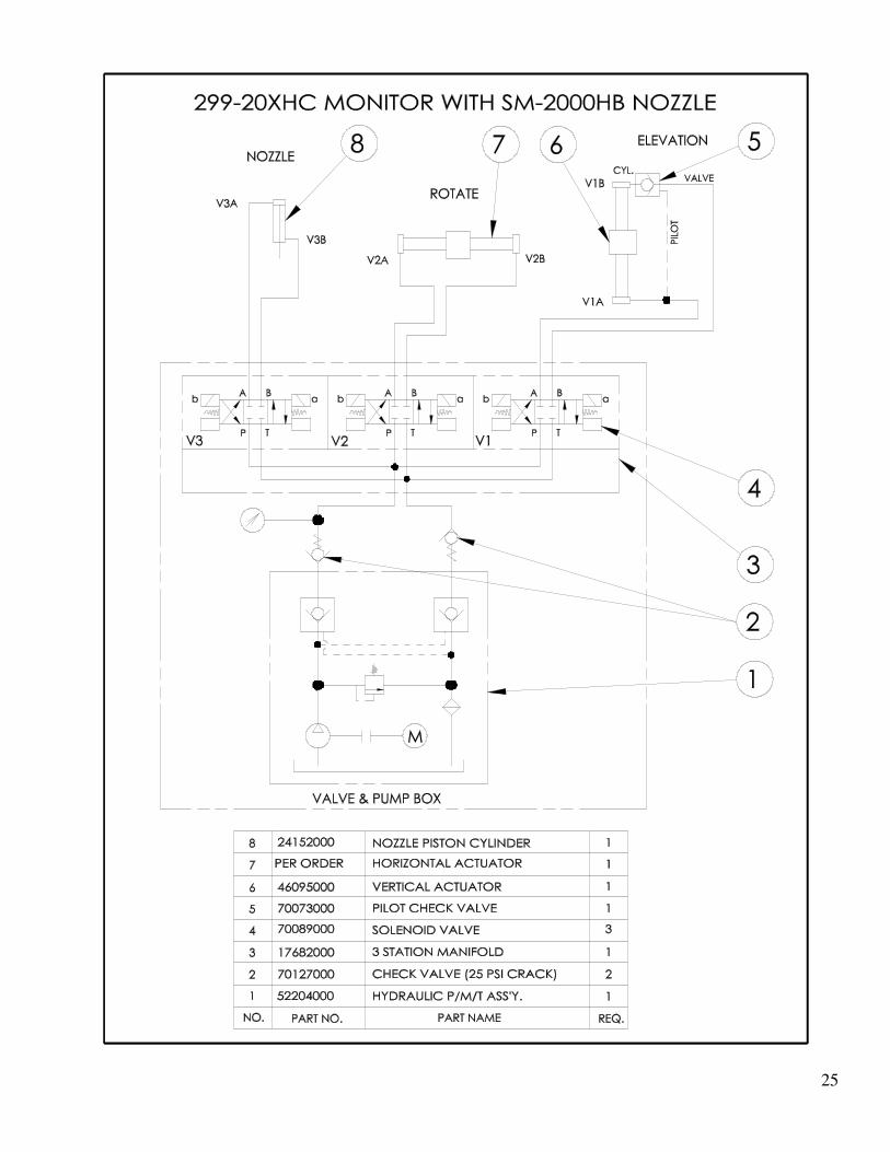
VII. MOUNTING DIMENSIONS AND REFERENCE DIAGRAMS
299-20 XHC
Mounted on Spool with Valve and Pump Box
23
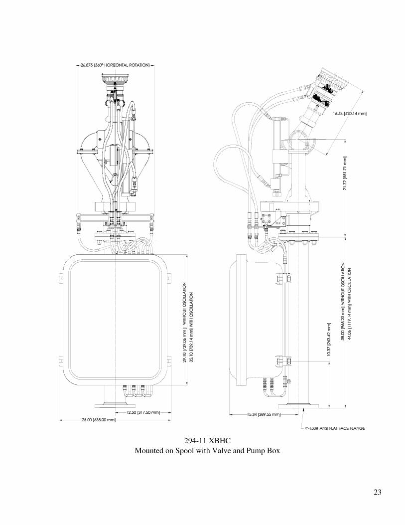
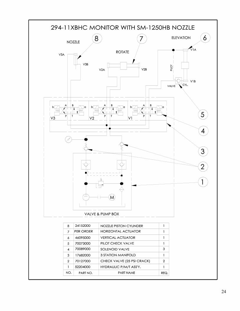
294-11 XBHC
Mounted on Spool with Valve and Pump Box
24
25
26
Typical Valve and Pump Box Wiring

27
VIII. SPARES
The following list of spares are not necessarily required but may be desired to keep on hand depending
on the environment and need for quick service. The regular maintenance schedule is a recommended
practice that influences both the life of the equipment and the need for component replacement as it
directly defines the environment the equipment must live in.

28
IX. CHANGE REVISION EXPLANATIONS

29
Elkhart Brass Mfg. Co. Inc. Elkhart , Indiana, USA
S h i p p i ng a d dr e s s
1 3 0 2 W e s t B e a r d s l e y Av e .
E l k h a r t , I n d i an a 4 6 5 1 4
M a i l i ng a d d re s s
P . O . B o x 1 1 2 7
E l k h a r t , I n d i an a 4 6 5 1 5
Phone: (574) 295-8330
(800) 346-0250
Fax: (574) 293-9914