Embed Size (px)
Citation preview
LUND UNIVERSITY
PO Box 117221 00 Lund+46 46-222 00 00
Industrial heating using energy efficient induction technology
Frogner, Kenneth; Andersson, Mats; Cedell, Tord; Siesing, Leif; Jeppsson, Peter; Ståhl, Jan-EricPublished in:Proceedings of the 44th CIRP International Conference on Manufacturing Systems
2011
Link to publication
Citation for published version (APA):Frogner, K., Andersson, M., Cedell, T., Siesing, L., Jeppsson, P., & Ståhl, J-E. (2011). Industrial heating usingenergy efficient induction technology. In K. Frogner (Ed.), Proceedings of the 44th CIRP InternationalConference on Manufacturing Systems
Total number of authors:6
General rightsUnless other specific re-use rights are stated the following general rights apply:Copyright and moral rights for the publications made accessible in the public portal are retained by the authorsand/or other copyright owners and it is a condition of accessing publications that users recognise and abide by thelegal requirements associated with these rights. • Users may download and print one copy of any publication from the public portal for the purpose of private studyor research. • You may not further distribute the material or use it for any profit-making activity or commercial gain • You may freely distribute the URL identifying the publication in the public portal
Read more about Creative commons licenses: https://creativecommons.org/licenses/Take down policyIf you believe that this document breaches copyright please contact us providing details, and we will removeaccess to the work immediately and investigate your claim.
Industrial heating using energy efficient induction technology
Kenneth Frogner, Mats Andersson, Tord Cedell, Leif Svensson, Peter Jeppsson, Jan-Eric Ståhl
Production and Materials Engineering Lund University, Sweden
Abstract The demands for energy efficent heating solutions for the manufacturing industry can be met by a new induction heating platform, presented in this article. A new concept and technology to design and manufacture induction heating unit is presented, as well as a prototype induction heater, evaluated and tested in an industrial environment. Improvements compared to existing heating solutions can be clearly shown, e.g. higher heating efficiency, no requirement for advanced cooling, a higher geometrical flexibility and also environmental gains. The Greenheat platform is built on Litz wiring, SMC flux conductors, and a casting technology which is outlined in the article. Keywords: Induction heating, Energy efficiency, SMC.
1. INTRODUCTION
New materials open up for improvements of induction heating equipment for industrial applications. The preservation of energy and energy efficiency will be key issues in a sustainable society. In this regard, induction heating is the most energy efficient heating technology in many applications, provided that the technology can be adapted to industrial needs and conditions. Such a condition would be to easily fit a heating unit onto an existing production line, another one would be to provide even and fast heating with a minimum of energy waste.
This article presents the results from a research project named Greenheat. This project has been part of a larger research programme, ProEnviro, financed by the Swedish Foundation for Strategic Research (SSF) and the Foundation for Strategic Environmental Research (Mistra), with a focus on developing sustainable technology for industry, also with a high market potential.
The Greenheat technology is the result of cross disciplinary research in a number of preceding research projects, ranging from basic electromagnetic circuit design and material characterisation, to development of manufacturing processes. By combining new materials with improved manufacturing methods, state of the art electronic components and well designed control systems, a greatly improved induction heating platform can be achieved. The new technology has the potential of not only reduce the energy consumption but also reduce production costs and cycle times compared to traditional methods.
The overall goal for the Greenheat project has been to develop a generic induction heating solution which can be adapted to different industrial applications with a small effort and setup cost. The research focus has been put on development of a new induction coil concept, the part of an induction heating platform having the highest improvement potential.
Quantified goals were mainly focused on the environmental performance of the induction heating unit, and specifically on the energy saving potential:
• Energy saving goal 1: Eliminate wasted energy for idle running furnaces.
• Energy saving goal 2: Demonstrate at least 50% reduced losses compared to electric or combustion furnaces, in a representative industrial application.
• Energy saving goal 3: Demonstrate at least 1/3 reduced losses when heating flat objects, compared to conventional inductive heating
• Reduce the magnetic leak fields down to 5% of today’s levels in conventional induction heating.
The fulfilment of these goals can be demonstrated in different ways, but will always involve some general estimation of the performance of existing industrial heating solutions.
2. STATE OF THE ART – INDUSTRIAL HEATING
The demand for controlled industrial heating is enormous in manufacturing industry all over the world. The applications range from brazing, heat treating, hardening, annealing, tempering and stress relieving to pre heating and shrink fitting, and more general purpose heating like bonding, sealing, soldering, crystal pulling, material testing, drying, curing, degassing, sintering etc.
Many of these heating operations are performed using fossil fuels and thus contributing to an increase of greenhouse gasses. Some of the operations are performed using induction heating, but where the energy efficiency can be greatly improved. The benefits with induction heating are not only related to energy savings; the total heating time and duty cycle can also be reduced, heat can be located to exact positions, decarburization, scaling, unwanted structural changes can be reduced etc.
However, conventional heating is still the dominant method, due to technical limitations in existing induction heating technology. Conventional heating is often performed in ovens or furnaces, powered by electricity or combustion of fossil fuels. They often represent a large investment and the energy efficiency is low. In addition to this, start-up times and lead times are long. Manual heating operations can be accomplished by using an

open flame. Heating processes are very common in industry and the heating installations that immediately could be replaced by induction heating represent huge values.
3. STATE OF THE ART – INDUCTION HEATING
Induction heating is a method of providing fast, consistent heat for numerous of applications, from low power cookers to demanding manufacturing systems. The process relies on induced electrical currents within the workpiece and works on all conductive materials, e.g. sheets, rolls or dies of metal. Depending on the geometry and the properties of the workpiece as well as the desired heating pattern, different frequencies of the alternating current is prefered. Low frequencies can be effective for thicker materials requiring deep heat penetration, while higher frequencies of up to about 400 kHz are used for smaller parts or shallow penetration. The current density is decreasing exponentially with the thickness of the conductor according to equation 1, where J is the current density at distance d from the surface, having the current density JS. δ is the skin depth, defining the distance from the surface to the point where the current density has decreased with e-1. δ is a material dependent parameter according to equation 2, where f is the frequency, ρ the resistivity and μ the permeability of the material.
dS eJJ /δ−⋅= [3] (1)
μπρδ⋅⋅
=f
[3] (2)
The heat is created from resistive losses and for ferromagnetic materials also from magnetic hysteresis losses. The hysteresis contribution decreases with the temperature up to the Curie point (770ºC for iron), where no effect is remaining.
The resistive losses Pe can be calculated using Ohm’s law, as I2·R, which under the assumption of uniform workpiece material, uniform magnetic field and sheet thicknesses d much smaller than the skin depth, can be stated as in equation 3, B denoting the magnetic flux density.[2] Non of the assumptions are correct; the skin depth should be significant smaller than the thickness of the workpiece for induction heating to work well, in reality the magnetic field is very large on the surface compared to in the center of the workpiece. The non-uniform heat distribution create non-uniform resistivity in the material and for ferromagnetic workpieces, also the permeability is changed by the temperature as well as by saturation in the surfaces. The approximation will not give reliable results, but gives an idea of which parameters affects the result.
ρπ
6
2222 fBdPe = [2] (3)
When applying a magnetic field to a ferromagnetic material, it is magnetized according to a hysteresis loop similar to figure 1. The energy to reach a certain state on the hysteresis curve equals the product of the H and the B-field, meaning a required contribution of energy of the same size as the area in the loop to complete a full period of de-magnetization and re-magnetization. The total hysteresis loss Pm can be obtained by integrating the magnetization energy over the entire volume V of the
workpiece, multiplied with the number of loops per second, equation 4. [3]
Figure 1. Typical magnetization curve for ferromagnetic materials.
∫∫ ⋅=⋅=VV
m dVHfdVBHfP 2μ [3] (4)
When comparing the equation for electric and magnetic losses, Pe and Pm, it can be noticed that the resistive heating has an f2 dependency while the hysteresis contribution is proportional to the frequency. The conclution from this is that it requires a higher switching frequency to heat non-ferrous materials. The other remark is the resistivity in the denominator of Pe, showing that it is easier to heat a workpiece with good conductivity. Finally, the heating power is proportional to the square of the magnetic field, cruicial for good result.
Induction heating is a versatile method with respect to geometry, material and power, still having very high energy efficiency, although not 100%. The undesired power losses Ploss can be divided into resistive losses created by the current I through the coil with resistance R according to equation 5. Also losses in the power electronics are present, typically in the range of 2-5% according to the manufacturers. In high temperature heating, the major loss is generally due to heat radiation caused by unsatisfactory isolation.
RIPloss ⋅= 2 [3] (5)
The basic components of an induction heating system are a switched mode frequency inverter, transformer, phase advancing filter capacitor, induction coil, and workpiece. The transformer is not cruicial, but frequently used to adapt the voltage and current from the power supply to the impedance of the coil, generating a magnetic field. The capacitors may be a part of the inverter or distributed to create the desired resonance frequency where the system has the best performance. When the workpiece is placed in the coil area, the magnetic field induces eddy currents in the workpiece, generating a well defined heat pattern without any physical contact between the coil and the workpiece.
Since the skin depth of copper at the typical frequencies for induction heating is significant smaler than 1 mm, the effective area of a solid copper bar as the conductor is very small. By driving a high current through this kind of wire would create a large amount of losses in the coil, increasing its temperature, which results in higher resistance of the bar and ever more losses. A better solution is to use copper tubing which has the same effective conduction area as the bar but also the space for running cooling water through it to keep the temperature and thereby the resistance low. This is the reason why most induction coils are made from copper tubing, typically with a diameter of 1/8" to 3/16" (4-6mm). The shape of the coil is to reflect the geometry of the part
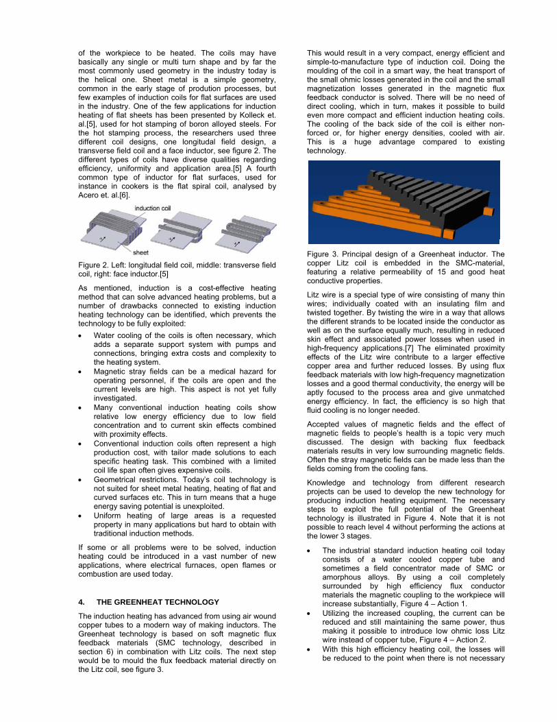
of the workpiece to be heated. The coils may have basically any single or multi turn shape and by far the most commonly used geometry in the industry today is the helical one. Sheet metal is a simple geometry, common in the early stage of prodution processes, but few examples of induction coils for flat surfaces are used in the industry. One of the few applications for induction heating of flat sheets has been presented by Kolleck et. al.[5], used for hot stamping of boron alloyed steels. For the hot stamping process, the researchers used three different coil designs, one longitudal field design, a transverse field coil and a face inductor, see figure 2. The different types of coils have diverse qualities regarding efficiency, uniformity and application area.[5] A fourth common type of inductor for flat surfaces, used for instance in cookers is the flat spiral coil, analysed by Acero et. al.[6].
Figure 2. Left: longitudal field coil, middle: transverse field coil, right: face inductor.[5]
As mentioned, induction is a cost-effective heating method that can solve advanced heating problems, but a number of drawbacks connected to existing induction heating technology can be identified, which prevents the technology to be fully exploited: • Water cooling of the coils is often necessary, which
adds a separate support system with pumps and connections, bringing extra costs and complexity to the heating system.
• Magnetic stray fields can be a medical hazard for operating personnel, if the coils are open and the current levels are high. This aspect is not yet fully investigated.
• Many conventional induction heating coils show relative low energy efficiency due to low field concentration and to current skin effects combined with proximity effects.
• Conventional induction coils often represent a high production cost, with tailor made solutions to each specific heating task. This combined with a limited coil life span often gives expensive coils.
• Geometrical restrictions. Today’s coil technology is not suited for sheet metal heating, heating of flat and curved surfaces etc. This in turn means that a huge energy saving potential is unexploited.
• Uniform heating of large areas is a requested property in many applications but hard to obtain with traditional induction methods.
If some or all problems were to be solved, induction heating could be introduced in a vast number of new applications, where electrical furnaces, open flames or combustion are used today.
4. THE GREENHEAT TECHNOLOGY
The induction heating has advanced from using air wound copper tubes to a modern way of making inductors. The Greenheat technology is based on soft magnetic flux feedback materials (SMC technology, described in section 6) in combination with Litz coils. The next step would be to mould the flux feedback material directly on the Litz coil, see figure 3.
This would result in a very compact, energy efficient and simple-to-manufacture type of induction coil. Doing the moulding of the coil in a smart way, the heat transport of the small ohmic losses generated in the coil and the small magnetization losses generated in the magnetic flux feedback conductor is solved. There will be no need of direct cooling, which in turn, makes it possible to build even more compact and efficient induction heating coils. The cooling of the back side of the coil is either non-forced or, for higher energy densities, cooled with air. This is a huge advantage compared to existing technology.
Figure 3. Principal design of a Greenheat inductor. The copper Litz coil is embedded in the SMC-material, featuring a relative permeability of 15 and good heat conductive properties.
Litz wire is a special type of wire consisting of many thin wires; individually coated with an insulating film and twisted together. By twisting the wire in a way that allows the different strands to be located inside the conductor as well as on the surface equally much, resulting in reduced skin effect and associated power losses when used in high-frequency applications.[7] The eliminated proximity effects of the Litz wire contribute to a larger effective copper area and further reduced losses. By using flux feedback materials with low high-frequency magnetization losses and a good thermal conductivity, the energy will be aptly focused to the process area and give unmatched energy efficiency. In fact, the efficiency is so high that fluid cooling is no longer needed.
Accepted values of magnetic fields and the effect of magnetic fields to people’s health is a topic very much discussed. The design with backing flux feedback materials results in very low surrounding magnetic fields. Often the stray magnetic fields can be made less than the fields coming from the cooling fans.
Knowledge and technology from different research projects can be used to develop the new technology for producing induction heating equipment. The necessary steps to exploit the full potential of the Greenheat technology is illustrated in Figure 4. Note that it is not possible to reach level 4 without performing the actions at the lower 3 stages.
• The industrial standard induction heating coil today consists of a water cooled copper tube and sometimes a field concentrator made of SMC or amorphous alloys. By using a coil completely surrounded by high efficiency flux conductor materials the magnetic coupling to the workpiece will increase substantially, Figure 4 – Action 1.
• Utilizing the increased coupling, the current can be reduced and still maintaining the same power, thus making it possible to introduce low ohmic loss Litz wire instead of copper tube, Figure 4 – Action 2.
• With this high efficiency heating coil, the losses will be reduced to the point when there is not necessary
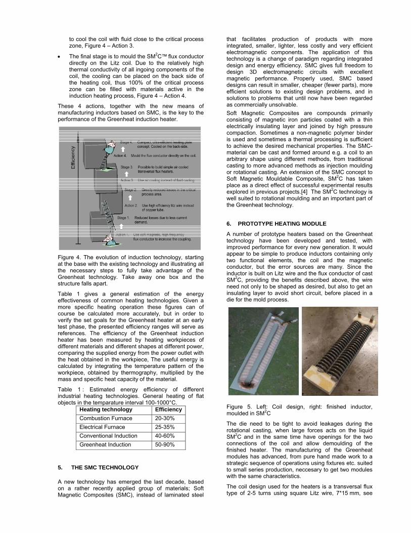
to cool the coil with fluid close to the critical process zone, Figure 4 – Action 3.
• The final stage is to mould the SM2C™ flux conductor directly on the Litz coil. Due to the relatively high thermal conductivity of all ingoing components of the coil, the cooling can be placed on the back side of the heating coil, thus 100% of the critical process zone can be filled with materials active in the induction heating process, Figure 4 – Action 4.
These 4 actions, together with the new means of manufacturing inductors based on SMC, is the key to the performance of the Greenheat induction heater.
Figure 4. The evolution of induction technology, starting at the base with the existing technology and illustrating all the necessary steps to fully take advantage of the Greenheat technology. Take away one box and the structure falls apart. Table 1 gives a general estimation of the energy effectiveness of common heating technologies. Given a more specific heating operation these figures can of course be calculated more accurately, but in order to verify the set goals for the Greenheat heater at an early test phase, the presented efficiency ranges will serve as references. The efficiency of the Greenheat induction heater has been measured by heating workpieces of different materials and different shapes at different power, comparing the supplied energy from the power outlet with the heat obtained in the workpiece, The useful energy is calculated by integrating the temperature pattern of the workpiece, obtained by thermography, multiplied by the mass and specific heat capacity of the material.
Table 1 : Estimated energy efficiency of different industrial heating technologies. General heating of flat objects in the temparature interval 100-1000°C.
Heating technology Efficiency Combustion Furnace 20-30% Electrical Furnace 25-35% Conventional Induction 40-60% Greenheat Induction 50-90%
5. THE SMC TECHNOLOGY A new technology has emerged the last decade, based on a rather recently applied group of materials; Soft Magnetic Composites (SMC), instead of laminated steel
that facilitates production of products with more integrated, smaller, lighter, less costly and very efficient electromagnetic components. The application of this technology is a change of paradigm regarding integrated design and energy efficiency. SMC gives full freedom to design 3D electromagnetic circuits with excellent magnetic performance. Properly used, SMC based designs can result in smaller, cheaper (fewer parts), more efficient solutions to existing design problems, and in solutions to problems that until now have been regarded as commercially unsolvable. Soft Magnetic Composites are compounds primarily consisting of magnetic iron particles coated with a thin electrically insulating layer and joined by high pressure compaction. Sometimes a non-magnetic polymer binder is used and sometimes a thermal processing is sufficient to achieve the desired mechanical properties. The SMC-material can be cast and formed around e.g. a coil to an arbitrary shape using different methods, from traditional casting to more advanced methods as injection moulding or rotational casting. An extension of the SMC concept to Soft Magnetic Mouldable Composite, SM2C has taken place as a direct effect of successful experimental results explored in previous projects.[4] The SM2C technology is well suited to rotational moulding and an important part of the Greenheat technology.
6. PROTOTYPE HEATING MODULE
A number of prototype heaters based on the Greenheat technology have been developed and tested, with improved performance for every new generation. It would appear to be simple to produce inductors containing only two functional elements, the coil and the magnetic conductor, but the error sources are many. Since the inductor is built on Litz wire and the flux conductor of cast SM2C, providing the benefits described above, the wire need not only to be shaped as desired, but also to get an insulating layer to avoid short circuit, before placed in a die for the mold process.
Figure 5. Left: Coil design, right: finished inductor, moulded in SM2C
The die need to be tight to avoid leakages during the rotational casting, when large forces acts on the liquid SM2C and in the same time have openings for the two connections of the coil and allow demoulding of the finished heater. The manufacturing of the Greenheat modules has advanced, from pure hand made work to a strategic sequence of operations using fixtures etc. suited to small series production, neccesary to get two modules with the same characteristics.
The coil design used for the heaters is a transversal flux type of 2-5 turns using square Litz wire, 7*15 mm, see
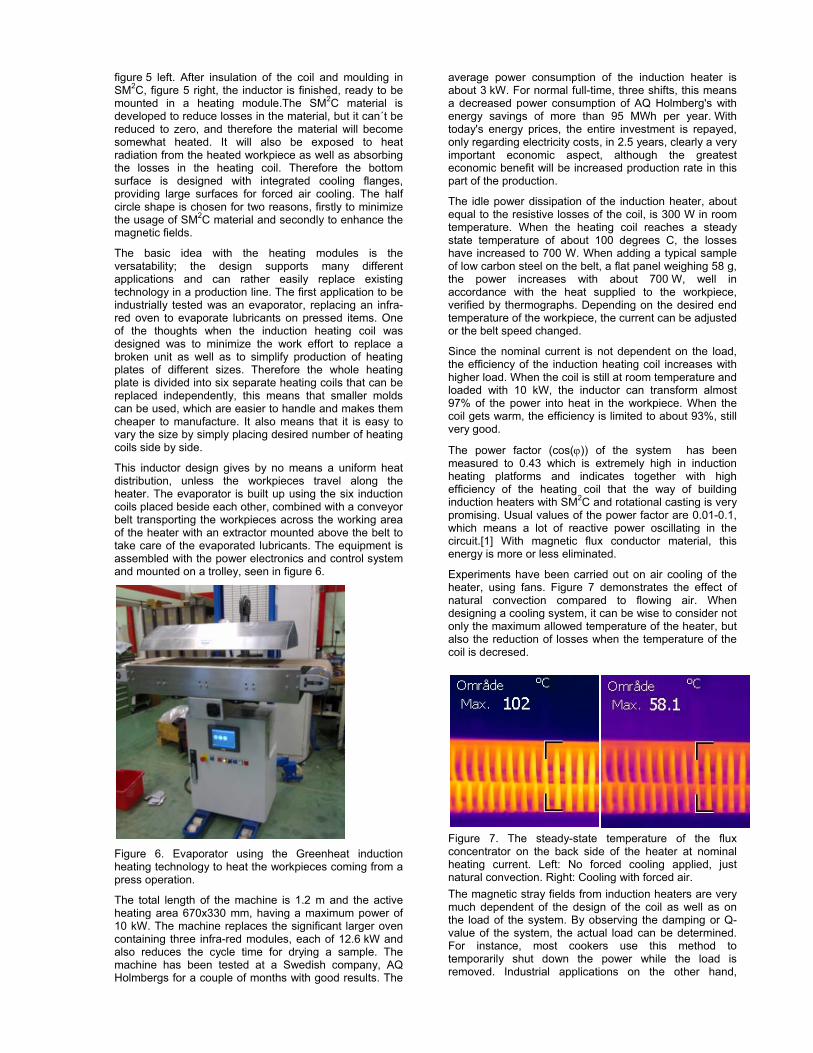
figure 5 left. After insulation of the coil and moulding in SM2C, figure 5 right, the inductor is finished, ready to be mounted in a heating module.The SM2C material is developed to reduce losses in the material, but it can´t be reduced to zero, and therefore the material will become somewhat heated. It will also be exposed to heat radiation from the heated workpiece as well as absorbing the losses in the heating coil. Therefore the bottom surface is designed with integrated cooling flanges, providing large surfaces for forced air cooling. The half circle shape is chosen for two reasons, firstly to minimize the usage of SM2C material and secondly to enhance the magnetic fields.
The basic idea with the heating modules is the versatability; the design supports many different applications and can rather easily replace existing technology in a production line. The first application to be industrially tested was an evaporator, replacing an infra-red oven to evaporate lubricants on pressed items. One of the thoughts when the induction heating coil was designed was to minimize the work effort to replace a broken unit as well as to simplify production of heating plates of different sizes. Therefore the whole heating plate is divided into six separate heating coils that can be replaced independently, this means that smaller molds can be used, which are easier to handle and makes them cheaper to manufacture. It also means that it is easy to vary the size by simply placing desired number of heating coils side by side.
This inductor design gives by no means a uniform heat distribution, unless the workpieces travel along the heater. The evaporator is built up using the six induction coils placed beside each other, combined with a conveyor belt transporting the workpieces across the working area of the heater with an extractor mounted above the belt to take care of the evaporated lubricants. The equipment is assembled with the power electronics and control system and mounted on a trolley, seen in figure 6.
Figure 6. Evaporator using the Greenheat induction heating technology to heat the workpieces coming from a press operation.
The total length of the machine is 1.2 m and the active heating area 670x330 mm, having a maximum power of 10 kW. The machine replaces the significant larger oven containing three infra-red modules, each of 12.6 kW and also reduces the cycle time for drying a sample. The machine has been tested at a Swedish company, AQ Holmbergs for a couple of months with good results. The
average power consumption of the induction heater is about 3 kW. For normal full-time, three shifts, this means a decreased power consumption of AQ Holmberg's with energy savings of more than 95 MWh per year. With today's energy prices, the entire investment is repayed, only regarding electricity costs, in 2.5 years, clearly a very important economic aspect, although the greatest economic benefit will be increased production rate in this part of the production.
The idle power dissipation of the induction heater, about equal to the resistive losses of the coil, is 300 W in room temperature. When the heating coil reaches a steady state temperature of about 100 degrees C, the losses have increased to 700 W. When adding a typical sample of low carbon steel on the belt, a flat panel weighing 58 g, the power increases with about 700 W, well in accordance with the heat supplied to the workpiece, verified by thermographs. Depending on the desired end temperature of the workpiece, the current can be adjusted or the belt speed changed.
Since the nominal current is not dependent on the load, the efficiency of the induction heating coil increases with higher load. When the coil is still at room temperature and loaded with 10 kW, the inductor can transform almost 97% of the power into heat in the workpiece. When the coil gets warm, the efficiency is limited to about 93%, still very good.
The power factor (cos(ϕ)) of the system has been measured to 0.43 which is extremely high in induction heating platforms and indicates together with high efficiency of the heating coil that the way of building induction heaters with SM2C and rotational casting is very promising. Usual values of the power factor are 0.01-0.1, which means a lot of reactive power oscillating in the circuit.[1] With magnetic flux conductor material, this energy is more or less eliminated.
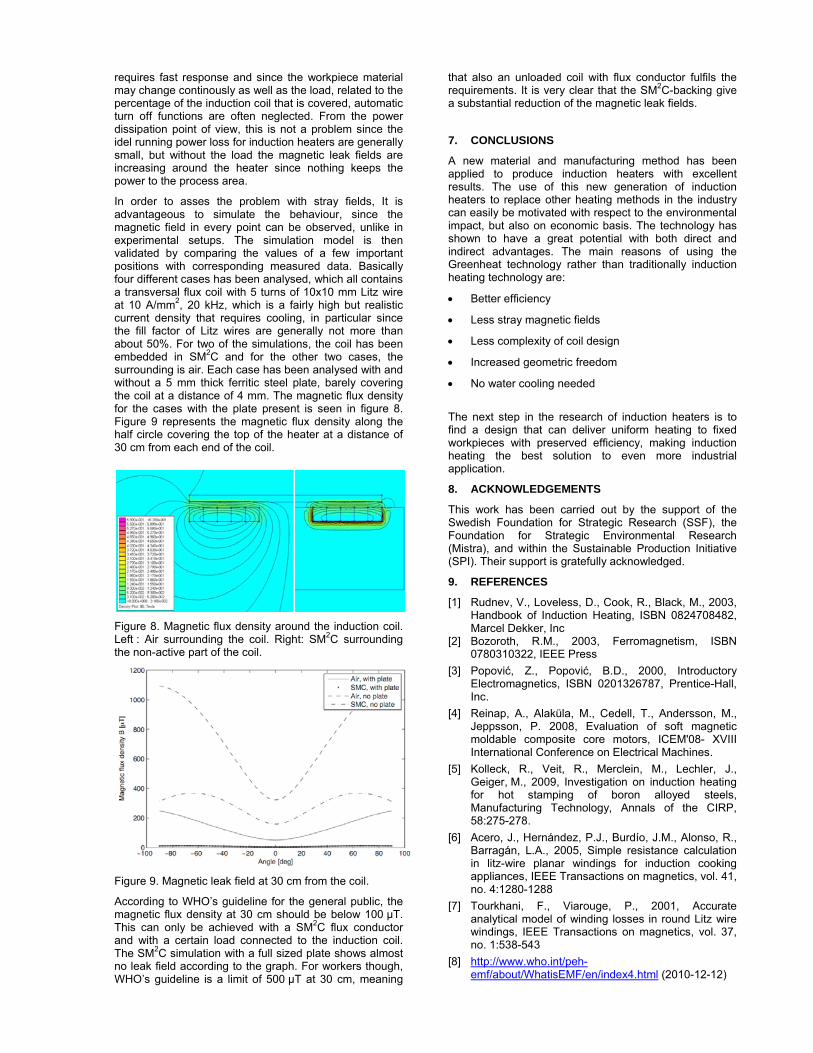
Experiments have been carried out on air cooling of the heater, using fans. Figure 7 demonstrates the effect of natural convection compared to flowing air. When designing a cooling system, it can be wise to consider not only the maximum allowed temperature of the heater, but also the reduction of losses when the temperature of the coil is decresed.
Figure 7. The steady-state temperature of the flux concentrator on the back side of the heater at nominal heating current. Left: No forced cooling applied, just natural convection. Right: Cooling with forced air. The magnetic stray fields from induction heaters are very much dependent of the design of the coil as well as on the load of the system. By observing the damping or Q-value of the system, the actual load can be determined. For instance, most cookers use this method to temporarily shut down the power while the load is removed. Industrial applications on the other hand,
requires fast response and since the workpiece material may change continously as well as the load, related to the percentage of the induction coil that is covered, automatic turn off functions are often neglected. From the power dissipation point of view, this is not a problem since the idel running power loss for induction heaters are generally small, but without the load the magnetic leak fields are increasing around the heater since nothing keeps the power to the process area.
In order to asses the problem with stray fields, It is advantageous to simulate the behaviour, since the magnetic field in every point can be observed, unlike in experimental setups. The simulation model is then validated by comparing the values of a few important positions with corresponding measured data. Basically four different cases has been analysed, which all contains a transversal flux coil with 5 turns of 10x10 mm Litz wire at 10 A/mm2, 20 kHz, which is a fairly high but realistic current density that requires cooling, in particular since the fill factor of Litz wires are generally not more than about 50%. For two of the simulations, the coil has been embedded in SM2C and for the other two cases, the surrounding is air. Each case has been analysed with and without a 5 mm thick ferritic steel plate, barely covering the coil at a distance of 4 mm. The magnetic flux density for the cases with the plate present is seen in figure 8. Figure 9 represents the magnetic flux density along the half circle covering the top of the heater at a distance of 30 cm from each end of the coil.
Figure 8. Magnetic flux density around the induction coil. Left : Air surrounding the coil. Right: SM2C surrounding the non-active part of the coil.
Figure 9. Magnetic leak field at 30 cm from the coil.
According to WHO’s guideline for the general public, the magnetic flux density at 30 cm should be below 100 μT. This can only be achieved with a SM2C flux conductor and with a certain load connected to the induction coil. The SM2C simulation with a full sized plate shows almost no leak field according to the graph. For workers though, WHO’s guideline is a limit of 500 μT at 30 cm, meaning
that also an unloaded coil with flux conductor fulfils the requirements. It is very clear that the SM2C-backing give a substantial reduction of the magnetic leak fields.
7. CONCLUSIONS
A new material and manufacturing method has been applied to produce induction heaters with excellent results. The use of this new generation of induction heaters to replace other heating methods in the industry can easily be motivated with respect to the environmental impact, but also on economic basis. The technology has shown to have a great potential with both direct and indirect advantages. The main reasons of using the Greenheat technology rather than traditionally induction heating technology are:
• Better efficiency
• Less stray magnetic fields
• Less complexity of coil design
• Increased geometric freedom
• No water cooling needed
The next step in the research of induction heaters is to find a design that can deliver uniform heating to fixed workpieces with preserved efficiency, making induction heating the best solution to even more industrial application.
8. ACKNOWLEDGEMENTS
This work has been carried out by the support of the Swedish Foundation for Strategic Research (SSF), the Foundation for Strategic Environmental Research (Mistra), and within the Sustainable Production Initiative (SPI). Their support is gratefully acknowledged.
9. REFERENCES
[1] Rudnev, V., Loveless, D., Cook, R., Black, M., 2003, Handbook of Induction Heating, ISBN 0824708482, Marcel Dekker, Inc
[2] Bozoroth, R.M., 2003, Ferromagnetism, ISBN 0780310322, IEEE Press
[3] Popović, Z., Popović, B.D., 2000, Introductory Electromagnetics, ISBN 0201326787, Prentice-Hall, Inc.
[4] Reinap, A., Alaküla, M., Cedell, T., Andersson, M., Jeppsson, P. 2008, Evaluation of soft magnetic moldable composite core motors, ICEM'08- XVIII International Conference on Electrical Machines.
[5] Kolleck, R., Veit, R., Merclein, M., Lechler, J., Geiger, M., 2009, Investigation on induction heating for hot stamping of boron alloyed steels, Manufacturing Technology, Annals of the CIRP, 58:275-278.
[6] Acero, J., Hernández, P.J., Burdío, J.M., Alonso, R., Barragán, L.A., 2005, Simple resistance calculation in litz-wire planar windings for induction cooking appliances, IEEE Transactions on magnetics, vol. 41, no. 4:1280-1288
[7] Tourkhani, F., Viarouge, P., 2001, Accurate analytical model of winding losses in round Litz wire windings, IEEE Transactions on magnetics, vol. 37, no. 1:538-543
[8] http://www.who.int/peh-emf/about/WhatisEMF/en/index4.html (2010-12-12)