Embed Size (px)
Citation preview
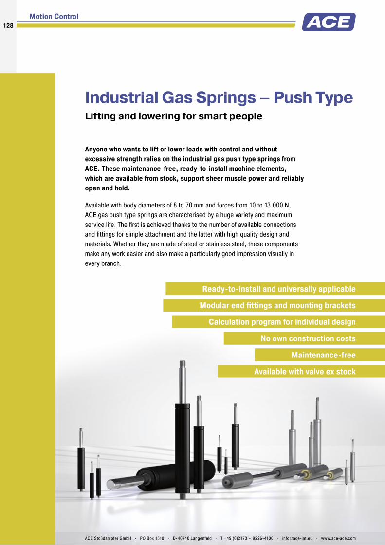
Industrial Gas Springs – Push TypeLifting and lowering for smart people
Anyone who wants to lift or lower loads with control and without
excessive strength relies on the industrial gas push type springs from
ACE. These maintenance-free, ready-to-install machine elements,
which are available from stock, support sheer muscle power and reliably
open and hold.
Available with body diameters of 8 to 70 mm and forces from 10 to 13,000 N,
ACE gas push type springs are characterised by a huge variety and maximum
service life. The fi rst is achieved thanks to the number of available connections
and fi ttings for simple attachment and the latter with high quality design and
materials. Whether they are made of steel or stainless steel, these components
make any work easier and also make a particularly good impression visually in
every branch.
Motion Control
Ready-to-install and universally applicable
Modular end fi ttings and mounting brackets
Calculation program for individual design
No own construction costs
Maintenance-free
Available with valve ex stock
128128
ACE Stoßdämpfer GmbH . PO Box 1510 . D-40740 Langenfeld . T +49 (0)2173 - 9226-4100 . [email protected] . www.ace-ace.com

Extension
55
Total Stroke mm
F3
FR
F1
F2
F4
Compression
Gas Springs (Push Type)
Type Progression
approx. %
1 Friction FR
approx. in N
GS-8 28 10
GS-10 20 10GS-12 25 20
GS-15 27 20
GS-19 26 - 39 2 30
GS-22 30 - 40 2 30
GS-28 58 - 67 2 40
GS-40 37 - 49 2 50
GS-70 25 50
1 Depending on the fi lling force 2 Depending on the stroke
Product Families
Overview
Industrial Gas Springs – Push Type
GS-8 to GS-70
Valve Technology Individual stroke length and extension forces
Hoods, Shutters, Machine housing, Conveyor systems
Page 130
GS-8-V4A to GS-40-VA
Valve Technology, Stainless Steel With food grade oil according to FDA approval
Hoods, Shutters, Machine housing, Conveyor systems
Page 140
GST-40 Tandem
Valve Technology Optimised dual force for heavy fl aps and wide angle
applications
Hoods, Shutters, Machine housing, Conveyor systems
Page 150
Free calculation service see page 168!
F1 = nominal force at 20 °C
(this is the pressure fi gure normally used when specifying the gas spring)
F2 = force in the complete compressed position
When compressing the piston rod, there is an additional friction force caused by the contact pressure of the seals (this only occurs during the compression stroke): F
3 = force at the beginning of the compression stroke
F4 = force at the end of the compression stroke
Calculation Principles
Force-Stroke Characteristics of Gas Spring (Push Type)
ACE gas springs are individually fi lled to a predetermined pressure to suit a customer’s require-ment (extension Force F
1). The cross-sectional area of the piston rod and fi lling pressure
determines the extension force.
During the compression of the piston rod, nitrogen fl ows through an orifi ce in the piston from the full bore side of the piston to the annulus. The nitrogen is compressed by the volume of the piston rod. As the piston rod is compressed the pressure increases, so increasing the reaction force (progression). The force depends on the proportional relationship between the piston rod and the inner tube diameter, which is approximately linear.
Function of a Gas Spring – Push Type
Progression: (the slope of the force line in the diagram above) is due to the reduction of the internal gas volume as the piston rod moves from its initial position to its fully stroked position. The approx. progression values given above for standard springs can be altered on request.
Effect of termperature: The nominal F1 fi gure is given at 20 °C.
An increase of 10 °C will increase force by 3.4 %.
Filling tolerances: 20 N to +40 N or 5 % to 7 %. Depending on size and extension force the tolerances can differ.
129
Issu
e 0
8.2
016
– S
pec
ifi ca
tio
ns s
ubje
ct t
o c
hang
e
ACE Stoßdämpfer GmbH . PO Box 1510 . D-40740 Langenfeld . T +49 (0)2173 - 9226-4100 . F +49 (0)2173 - 9226-89 . [email protected] . www.ace-ace.com

Metering Orifice for Controlled Velocities
Filled with High Pressure Nitrogen Gas
Valve
Oil Zone for End Position Damping
Seals
Outer Body
Grease Chamber for Low Breakaway Force
Main Bearing
Piston Rod
Thread for End Fittings
Technical Data
Universal and tailor made: ACE industrial gas push type springs of the NEWTONLINE family offer perfect support of muscle power with forces from 10 to 13,000 N with body diameter of 8 to 70 mm. With their high quality features the NEWTONLINE gas springs form the industry standard. These durable and sealed systems are ready for installation, maintenance-free and fi lled with pressurised nitrogen gas.
They are supplied fi lled according to individual customer pressure requirements and maybe adjusted later by use of the inbuilt valve. The free of charge ACE calculation service designs the gas springs with mounting points specifi cally for the particular application. A variety of additional components makes assembly even easier and allows universal application of the gas springs.
ACE industrial gas push type springs are used in industrial applications, mechanical engineering and medical technology as well as in the electronics, automobile and furniture industries.
GS-8 to GS-70Industrial Gas Springs – Push Type
Individual stroke length and extension forces
Industrial Gas Springs – Push Type
Valve Technology
Force range: 10 N to 13,000 N
Piston rod diameter: Ø 3 mm to Ø 30 mm
Progression: Approx. 20 % to 67 % (depending on size and stroke)
Lifetime: Approx. 10,000 m
Operating temperature range: -20 °C to +80 °C
Material: Outer body: Coated steel; Piston rod: Steel or stainless steel with wear-resistant coating; End fi ttings: Zinc plated steel
Operating fl uid: Nitrogen gas and oil
Mounting: We recommend mounting with piston rod downwards to take advantage of the built-in end position damping.
End position damping length: Approx. 5 mm to 70 mm (depending on the stroke)
Positive stop: External positive stop at the end of stroke provided by the customer.
Application fi eld: Hoods, Shutters, Machine housing, Conveyor systems
Note: Increased break-away force if unit has not moved for some time.
End fi ttings: They are interchangeable and must be positively secured by the customer to prevent unscrewing.
Safety instructions: Gas springs (push type) should not be installed under pre-tension.
On request: Special oils and other special options. Alternative accessories. Different end position damping and extension speed.
130
Issu
e 0
8.2
016
– S
pec
ifi ca
tio
ns s
ubje
ct t
o c
hang
e
ACE Stoßdämpfer GmbH . PO Box 1510 . D-40740 Langenfeld . T +49 (0)2173 - 9226-4100 . F +49 (0)2173 - 9226-89 . [email protected] . www.ace-ace.com
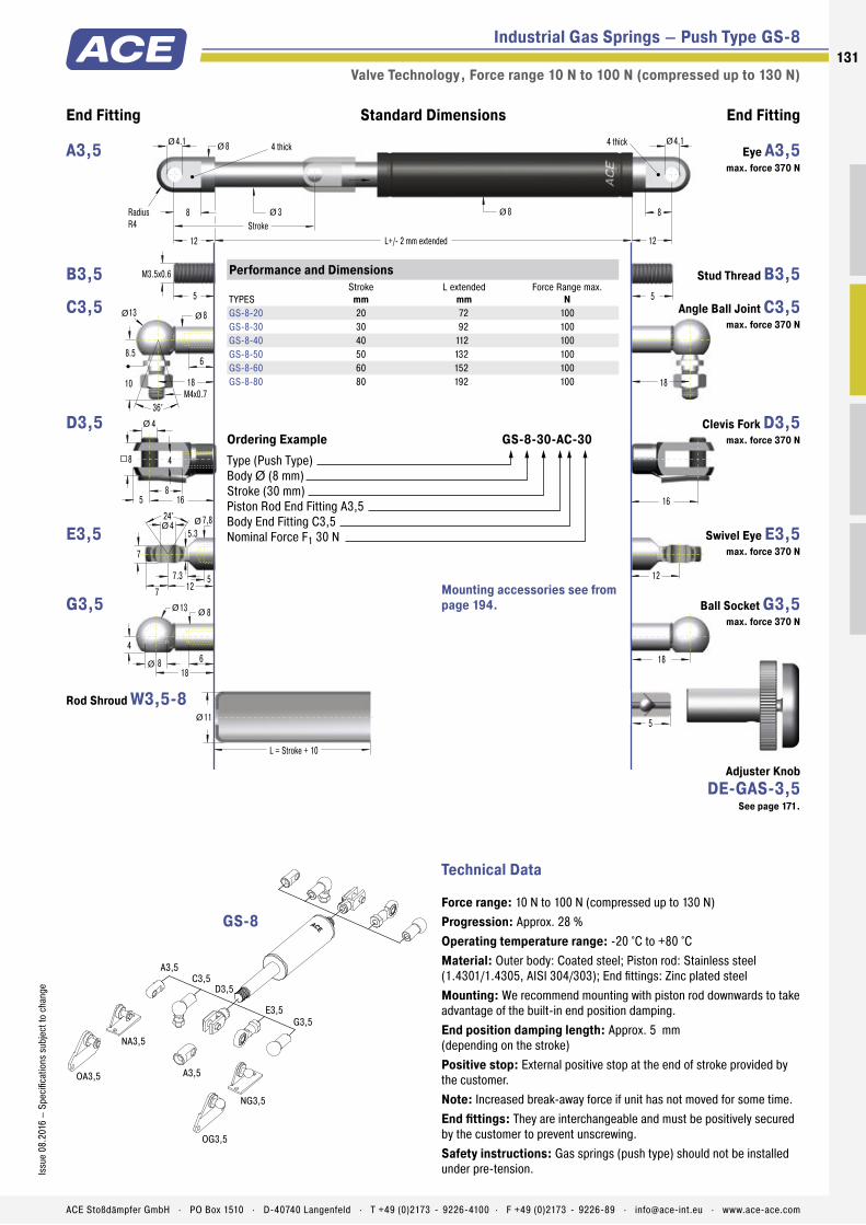
Industrial Gas Springs – Push Type GS-8
Valve Technology , Force range 10 N to 100 N (compressed up to 130 N)
End Fitting End FittingStandard Dimensions
5
24° 7,8 4
5
5.3
712
7.3
ØØ
7
18
18
4
138
68
5
M3.5x0.6
18
8
8
12 L+/- 2 mm extended
3
4.1
Stroke
Radius
R4
4 thick
12
4 thick
8 8
L = Stroke + 10
11
ØØ
Ø
Ø Ø
ØØ
4
8
4
5 16
8
Ø
Ø
Ø
18
M4x0.7
8.5
13 8
6
10
36°
Ø Ø
5
4.1
16
12
A3,5
NG3,5
NA3,5
OG3,5
OA3,5
C3,5D3,5
E3,5
G3,5
A3,5
Technical Data
Force range: 10 N to 100 N (compressed up to 130 N)
Progression: Approx. 28 %
Operating temperature range: -20 °C to +80 °C
Material: Outer body: Coated steel; Piston rod: Stainless steel (1.4301/1.4305, AISI 304/303); End fi ttings: Zinc plated steel
Mounting: We recommend mounting with piston rod downwards to take advantage of the built-in end position damping.
End position damping length: Approx. 5 mm (depending on the stroke)
Positive stop: External positive stop at the end of stroke provided by the customer.
Note: Increased break-away force if unit has not moved for some time.
End fi ttings: They are interchangeable and must be positively secured by the customer to prevent unscrewing.
Safety instructions: Gas springs (push type) should not be installed under pre-tension.
Performance and Dimensions
TYPES
Stroke
mm
L extended
mm
Force Range max.
N
GS-8-20 20 72 100
GS-8-30 30 92 100
GS-8-40 40 112 100
GS-8-50 50 132 100
GS-8-60 60 152 100
GS-8-80 80 192 100
Ordering Example GS-8-30-AC-30
Type (Push Type)
Body Ø (8 mm)
Stroke (30 mm)
Piston Rod End Fitting A3,5
Body End Fitting C3,5
Nominal Force F1 30 N
GS-8
Mounting accessories see from
page 194.
Eye A3,5
max. force 370 N
A3,5
Stud Thread B3,5 B3,5
Angle Ball Joint C3,5
max. force 370 N
C3,5
Clevis Fork D3,5
max. force 370 N
D3,5
Swivel Eye E3,5
max. force 370 N
E3,5
Ball Socket G3,5
max. force 370 N
G3,5
Rod Shroud W3,5-8
Adjuster Knob
DE-GAS-3,5
See page 171.
131
Issu
e 0
8.2
016
– S
pec
ifi ca
tio
ns s
ubje
ct t
o c
hang
e
ACE Stoßdämpfer GmbH . PO Box 1510 . D-40740 Langenfeld . T +49 (0)2173 - 9226-4100 . F +49 (0)2173 - 9226-89 . [email protected] . www.ace-ace.com

Industrial Gas Springs – Push Type GS-10
Valve Technology , Force range 10 N to 100 N (compressed up to 120 N)
End Fitting End FittingStandard Dimensions
5
24° 7.8 4
5
5.3
712
7.3
ØØ
7
18
18
4
138
68
5
M3.5x0.6
18
8
8
12 L+/- 2 mm extended
3
4.1
Stroke
Radius
R4
4 thick
12
4 thick
10 8
L = Stroke + 10
13
ØØ
Ø
Ø Ø
ØØ
4
8
4
5 16
8
Ø
Ø
Ø
18
M4x0.7
8.5
13 8
6
10
36°
Ø Ø
5
4.1
16
12
A3,5
NG3,5
NA3,5
OG3,5
OA3,5
C3,5D3,5
E3,5
G3,5
A3,5
Technical Data
Force range: 10 N to 100 N (compressed up to 120 N)
Progression: Approx. 28 %
Operating temperature range: -20 °C to +80 °C
Material: Outer body: Coated steel; Piston rod: Stainless steel (1.4301/1.4305, AISI 304/303); End fittings: Zinc plated steel
Mounting: We recommend mounting with piston rod downwards to take advantage of the built-in end position damping.
End position damping length: Approx. 5 mm (depending on the stroke)
Positive stop: External positive stop at the end of stroke provided by the customer.
Note: Increased break-away force if unit has not moved for some time.
End fittings: They are interchangeable and must be positively secured by the customer to prevent unscrewing.
Safety instructions: Gas springs (push type) should not be installed under pre-tension.
Performance and Dimensions
TYPES
Stroke
mm
L extended
mm
Force Range max.
N
GS-10-20 20 72 100
GS-10-30 30 92 100
GS-10-40 40 112 100
GS-10-50 50 132 100
GS-10-60 60 152 100
GS-10-80 80 192 100
Ordering Example GS-10-80-AC-60
Type (Push Type)
Body Ø (10 mm)
Stroke (80 mm)
Piston Rod End Fitting A3,5
Body End Fitting C3,5
Nominal Force F1 60 N
GS-10
Mounting accessories see from
page 194.
Eye A3,5
max. force 370 N
A3,5
Stud Thread B3,5 B3,5
Angle Ball Joint C3,5
max. force 370 N
C3,5
Clevis Fork D3,5
max. force 370 N
D3,5
Swivel Eye E3,5
max. force 370 N
E3,5
Ball Socket G3,5
max. force 370 N
G3,5
Rod Shroud W3,5-10
Adjuster Knob
DE-GAS-3,5
See page 171.
132
Issu
e 0
8.2
016
– S
peci
ficat
ion
s su
bje
ct t
o c
han
ge
ACE Stoßdämpfer GmbH . PO Box 1510 . D-40740 Langenfeld . T +49 (0)2173 - 9226-4100 . F +49 (0)2173 - 9226-89 . [email protected] . www.ace-ace.com

Industrial Gas Springs – Push Type GS-12
Valve Technology , Force range 15 N to 180 N (compressed up to 225 N)
End Fitting End FittingStandard Dimensions
5
24° 7.8 4
5
5.3
712
7.3
ØØ
7
18
18
4
138
68
5
M3.5x0.6
18
8
8
12 L+/- 2 mm extended
4
4.1
Stroke
Radius
R4
4 thick
12
4 thick
12 8
L = Stroke + 10
15.6
ØØ
Ø
Ø Ø
ØØ
4
8
4
5 16
8
Ø
Ø
Ø
18
M4x0.7
8.5
13 8
6
10
36°
Ø Ø
5
4.1
16
12
A3,5
NG3,5
NA3,5
OG3,5
OA3,5
C3,5D3,5
E3,5
G3,5
A3,5
Technical Data
Force range: 15 N to 180 N (compressed up to 225 N)
Progression: Approx. 25 %
Operating temperature range: -20 °C to +80 °C
Material: Outer body: Coated steel; Piston rod: Stainless steel (1.4301/1.4305, AISI 304/303); End fittings: Zinc plated steel
Mounting: We recommend mounting with piston rod downwards to take advantage of the built-in end position damping.
End position damping length: Approx. 10 mm (depending on the stroke)
Positive stop: External positive stop at the end of stroke provided by the customer.
Note: Increased break-away force if unit has not moved for some time.
End fittings: They are interchangeable and must be positively secured by the customer to prevent unscrewing.
Safety instructions: Gas springs (push type) should not be installed under pre-tension.
Performance and Dimensions
TYPES
Stroke
mm
L extended
mm
Force Range max.
N
GS-12-20 20 72 180
GS-12-30 30 92 180
GS-12-40 40 112 180
GS-12-50 50 132 180
GS-12-60 60 152 180
GS-12-80 80 192 150
GS-12-100 100 232 150
GS-12-120 120 272 120
GS-12-150 150 332 100
Ordering Example GS-12-100-AA-30
Type (Push Type)
Body Ø (12 mm)
Stroke (100 mm)
Piston Rod End Fitting A3,5
Body End Fitting A3,5
Nominal Force F1 30 N
GS-12
Mounting accessories see from
page 194.
Eye A3,5
max. force 370 N
A3,5
Stud Thread B3,5 B3,5
Angle Ball Joint C3,5
max. force 370 N
C3,5
Clevis Fork D3,5
max. force 370 N
D3,5
Swivel Eye E3,5
max. force 370 N
E3,5
Ball Socket G3,5
max. force 370 N
G3,5
Rod Shroud W3,5-12
Adjuster Knob
DE-GAS-3,5
See page 171.
133
Issu
e 0
8.2
016
– S
peci
ficat
ion
s su
bje
ct t
o c
han
ge
ACE Stoßdämpfer GmbH . PO Box 1510 . D-40740 Langenfeld . T +49 (0)2173 - 9226-4100 . F +49 (0)2173 - 9226-89 . [email protected] . www.ace-ace.com

Industrial Gas Springs – Push Type GS-15
Valve Technology , Force range 40 N to 400 N (compressed up to 500 N)
End Fitting End FittingStandard Dimensions
5
22
28
30
20
22
4.5
138
128
1028
AF13
20
45°M5x0.8
8
24° 10 6
6
5
10
5
6 20
10
5
M5x0.8
22
10
10
16 L+/- 2 mm extended
6
6.1
Stroke
Radius
R5
6 thick
16
6 thick
15.6 10
L = Stroke + 20
19
22
M5x0.8
8
13 8
12
10
36°
12
13
4.5
1030
12
Ø
Ø Ø
Ø
ØØ
Ø
Ø Ø
Ø
ØØ
Ø
Ø
Ø
5
6.1
Ø
A5
MA5
MA5
NG5
NA5
OG5
OA5
PA5
PG5
C5D5
E5
G5
NA5
OA5
PA5
F5
Performance and Dimensions
TYPES
Stroke
mm
L extended
mm
Force Range max.
N
GS-15-20 20 67 400
GS-15-40 40 107 400
GS-15-50 50 127 400
GS-15-60 60 147 400
GS-15-80 80 187 400
GS-15-100 100 227 400
GS-15-120 120 267 400
GS-15-150 150 327 400
GS-15-200 200 427 400
Ordering Example GS-15-150-AC-150
Type (Push Type)
Body Ø (15.6 mm)
Stroke (150 mm)
Piston Rod End Fitting A5
Body End Fitting C5
Nominal Force F1 150 N
GS-15
Mounting accessories see from
page 194.
Eye A5
max. force 800 N
A5
Stud Thread B5 B5
Angle Ball Joint C5
max. force 500 N
C5
Clevis Fork D5
max. force 800 N
D5
Swivel Eye E5
max. force 800 N
E5
Inline Ball Joint F5
max. force 500 N
F5
Ball Socket G5
max. force 500 N
G5
Rod Shroud W5-15
Technical Data
Force range: 40 N to 400 N (compressed up to 500 N)
Progression: Approx. 27 %
Operating temperature range: -20 °C to +80 °C
Material: Outer body: Steel coated with UV paint; Piston rod: Steel with wear-resistant coating; End fittings: Zinc plated steel
Mounting: We recommend mounting with piston rod downwards to take advantage of the built-in end position damping.
End position damping length: Approx. 10 mm (depending on the stroke)
Positive stop: External positive stop at the end of stroke provided by the customer.
Note: Increased break-away force if unit has not moved for some time.
End fittings: They are interchangeable and must be positively secured by the customer to prevent unscrewing.
Safety instructions: Gas springs (push type) should not be installed under pre-tension.
Adjuster Knob
DE-GAS-5
See page 171.
134
Issu
e 0
8.2
016
– S
peci
ficat
ion
s su
bje
ct t
o c
han
ge
ACE Stoßdämpfer GmbH . PO Box 1510 . D-40740 Langenfeld . T +49 (0)2173 - 9226-4100 . F +49 (0)2173 - 9226-89 . [email protected] . www.ace-ace.com
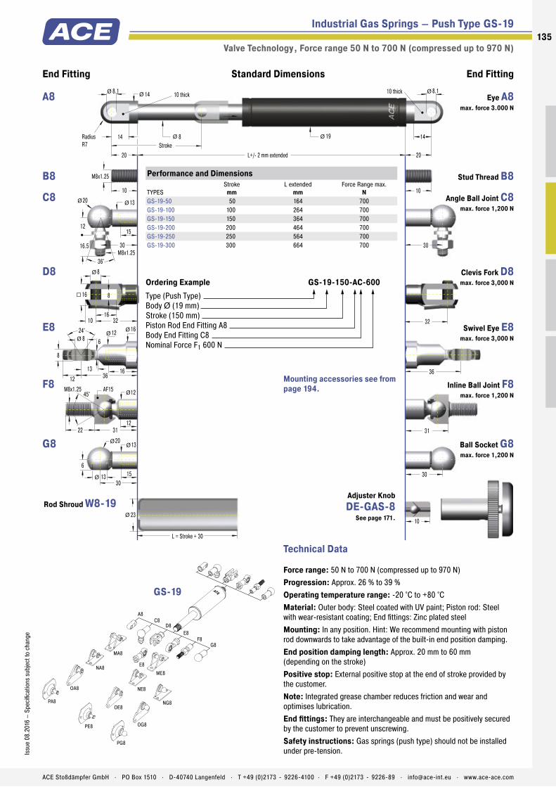
Industrial Gas Springs – Push Type GS-19
Valve Technology , Force range 50 N to 700 N (compressed up to 970 N)
End Fitting End FittingStandard Dimensions
10
30
31
36
32
30
6
2013
1513
1231
AF15
22
45°M8x1.25
12
24° 12 8
8
8
16
8
10 32
16
10
M8x1.25
30
14
14
20 L+/- 2 mm extended
8
8.1
Stroke
Radius
R7
10 thick
20
10 thick
19 14
L = Stroke + 30
23
30
M8x1.25
12
20 13
15
16.5
36°
16
16
6
1236
13
Ø
Ø Ø
Ø
ØØ
Ø
Ø Ø
Ø
ØØ
Ø
Ø
Ø
10
8.1
Ø
A8
MA8
NG8
NA8
OG8
OA8
PA8
PG8
C8D8
E8
G8F8
ME8
NE8
OE8
PE8
E8
Performance and Dimensions
TYPES
Stroke
mm
L extended
mm
Force Range max.
N
GS-19-50 50 164 700
GS-19-100 100 264 700
GS-19-150 150 364 700
GS-19-200 200 464 700
GS-19-250 250 564 700
GS-19-300 300 664 700
Ordering Example GS-19-150-AC-600
Type (Push Type)
Body Ø (19 mm)
Stroke (150 mm)
Piston Rod End Fitting A8
Body End Fitting C8
Nominal Force F1 600 N
GS-19
Mounting accessories see from
page 194.
Eye A8
max. force 3.000 N
A8
Stud Thread B8 B8
Angle Ball Joint C8
max. force 1,200 N
C8
Clevis Fork D8
max. force 3,000 N
D8
Swivel Eye E8
max. force 3,000 N
E8
Inline Ball Joint F8
max. force 1,200 N
F8
Ball Socket G8
max. force 1,200 N
G8
Rod Shroud W8-19Adjuster Knob
DE-GAS-8
See page 171.
Technical Data
Force range: 50 N to 700 N (compressed up to 970 N)
Progression: Approx. 26 % to 39 %
Operating temperature range: -20 °C to +80 °C
Material: Outer body: Steel coated with UV paint; Piston rod: Steel with wear-resistant coating; End fittings: Zinc plated steel
Mounting: In any position. Hint: We recommend mounting with piston rod downwards to take advantage of the built-in end position damping.
End position damping length: Approx. 20 mm to 60 mm (depending on the stroke)
Positive stop: External positive stop at the end of stroke provided by the customer.
Note: Integrated grease chamber reduces friction and wear and optimises lubrication.
End fittings: They are interchangeable and must be positively secured by the customer to prevent unscrewing.
Safety instructions: Gas springs (push type) should not be installed under pre-tension.
135
Issu
e 0
8.2
016
– S
peci
ficat
ion
s su
bje
ct t
o c
han
ge
ACE Stoßdämpfer GmbH . PO Box 1510 . D-40740 Langenfeld . T +49 (0)2173 - 9226-4100 . F +49 (0)2173 - 9226-89 . [email protected] . www.ace-ace.com

Industrial Gas Springs – Push Type GS-22
Valve Technology , Force range 80 N to 1,300 N (compressed up to 1,820 N)
End Fitting End FittingStandard Dimensions
10
30
31
36
32
30
6
2013
1513
1231
AF15
22
45°M8x1.25
12
24° 12 8
8
8
16
8
10 32
16
10
M8x1.25
30
14
14
20 L+/- 2 mm extended
10
8.1
Stroke
Radius
R7
10 thick
20
10 thick
23 14
L = Stroke + 30
28
30
M8x1.25
12
20 13
15
16.5
36°
16
16
6
1236
13
Ø
Ø Ø
Ø
ØØ
Ø
Ø Ø
Ø
ØØ
Ø
Ø
Ø
10
8.1
Ø
A8
MA8
NG8
NA8
OG8
OA8
PA8
PG8
C8D8
E8
G8F8
ME8
NE8
OE8
PE8
E8
Performance and Dimensions
TYPES
Stroke
mm
L extended
mm
Force Range max.
N
GS-22-50 50 164 1,300
GS-22-100 100 264 1,300
GS-22-150 150 364 1,300
GS-22-200 200 464 1,300
GS-22-250 250 564 1,300
GS-22-300 300 664 1,300
GS-22-350 350 764 1,300
GS-22-400 400 864 1,300
GS-22-450 450 964 1,300
GS-22-500 500 1,064 1,300
GS-22-550 550 1,164 1,300
GS-22-600 600 1,264 1,300
GS-22-650 650 1,364 1,300
GS-22-700 700 1,464 1,300
Ordering Example GS-22-150-AE-800
Type (Push Type)
Body Ø (23 mm)
Stroke (150 mm)
Piston Rod End Fitting A8
Body End Fitting E8
Nominal Force F1 800 N
GS-22
Mounting accessories see from
page 194.
Eye A8
max. force 3.000 N
A8
Stud Thread B8 B8
Angle Ball Joint C8
max. force 1,200 N
C8
Clevis Fork D8
max. force 3,000 N
D8
Swivel Eye E8
max. force 3,000 N
E8
Inline Ball Joint F8
max. force 1,200 N
F8
Ball Socket G8
max. force 1,200 N
G8
Rod Shroud W8-22Adjuster Knob
DE-GAS-8
See page 171.
Technical Data
Force range: 80 N to 1,300 N (compressed up to 1,820 N)
Progression: Approx. 30 % to 40 %
Operating temperature range: -20 °C to +80 °C
Material: Outer body: Steel coated with UV paint; Piston rod: Steel with wear-resistant coating; End fittings: Zinc plated steel
Mounting: In any position. Hint: We recommend mounting with piston rod downwards to take advantage of the built-in end position damping.
End position damping length: Approx. 20 mm to 70 mm (depending on the stroke)
Positive stop: External positive stop at the end of stroke provided by the customer.
Note: Integrated grease chamber reduces friction and wear and optimises lubrication.
End fittings: They are interchangeable and must be positively secured by the customer to prevent unscrewing.
Safety instructions: Gas springs (push type) should not be installed under pre-tension.
136
Issu
e 0
8.2
016
– S
peci
ficat
ion
s su
bje
ct t
o c
han
ge
ACE Stoßdämpfer GmbH . PO Box 1510 . D-40740 Langenfeld . T +49 (0)2173 - 9226-4100 . F +49 (0)2173 - 9226-89 . [email protected] . www.ace-ace.com

Industrial Gas Springs – Push Type GS-28
Valve Technology , Force range 150 N to 2,500 N (compressed up to 4,175 N)
End Fitting End FittingStandard Dimensions
12
40
10
20
10
12 40
20
12
M10x1.5
35
18
17
25 L+/- 2 mm extended
14
8.1
Stroke
Radius
R9
12 thick
25
12 thick
28 17
L = Stroke + 40
32
35
M10x1.5
16
24 16
18
20
36°
Ø
Ø Ø
Ø Ø
Ø
43
43
Ø
Ø
Ø
12
8.1
24° 15 10
9
18
19
7
1443
16
ØØ
Ø
1943
AF17
25
45°M10x1.5 AF17
A10
MA10
ME10
C10D10
E10
F10
OE10
PE10
E10
Technical Data
Force range: 150 N to 2,500 N (compressed up to 4,175 N)
Progression: Approx. 58 % to 67 %
Operating temperature range: -20 °C to +80 °C
Material: Outer body: Steel coated with UV paint; Piston rod: Steel with wear-resistant coating; End fittings: Zinc plated steel
Mounting: In any position. Hint: We recommend mounting with piston rod downwards to take advantage of the built-in end position damping.
End position damping length: Approx. 30 mm to 70 mm (depending on the stroke)
Positive stop: External positive stop at the end of stroke provided by the customer.
Note: Integrated grease chamber reduces friction and wear and optimises lubrication.
End fittings: They are interchangeable and must be positively secured by the customer to prevent unscrewing.
Safety instructions: Gas springs (push type) should not be installed under pre-tension.
Performance and Dimensions
TYPES
Stroke
mm
L extended
mm
Force Range max.
N
GS-28-100 100 262 2,500
GS-28-150 150 362 2,500
GS-28-200 200 462 2,500
GS-28-250 250 562 2,500
GS-28-300 300 662 2,500
GS-28-350 350 762 2,500
GS-28-400 400 862 2,500
GS-28-450 450 962 2,500
GS-28-500 500 1,062 2,500
GS-28-550 550 1,162 2,500
GS-28-600 600 1,262 2,500
GS-28-650 650 1,362 2,500
GS-28-700 700 1,462 2,500
GS-28-750 750 1,562 2,500
Ordering Example GS-28-150-EE-1200
Type (Push Type)
Body Ø (28 mm)
Stroke (150 mm)
Piston Rod End Fitting E10
Body End Fitting E10
Nominal Force F1 1200 N
GS-28
Mounting accessories see from
page 194.
Eye A10
max. force 10,000 N
A10
Stud Thread B10 B10
Angle Ball Joint C10
max. force 1,800 N
C10
Clevis Fork D10
max. force 10,000 N
D10
Swivel Eye E10
max. force 10,000 N
E10
Inline Ball Joint F10
max. force 1,800 N
F10
Rod Shroud W10-28
Adjuster Knob
DE-GAS-10
See page 171.
137
Issu
e 0
8.2
016
– S
peci
ficat
ion
s su
bje
ct t
o c
han
ge
ACE Stoßdämpfer GmbH . PO Box 1510 . D-40740 Langenfeld . T +49 (0)2173 - 9226-4100 . F +49 (0)2173 - 9226-89 . [email protected] . www.ace-ace.com
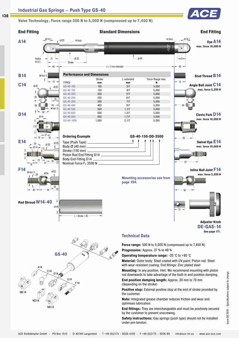
Industrial Gas Springs – Push Type GS-40
Valve Technology , Force range 500 N to 5,000 N (compressed up to 7,450 N)
End Fitting End FittingStandard Dimensions
15
56
14
27
14
16 56
27
15
M14x1.5
45
25
21
40 L+/- 2 mm extended
20
14.1
Stroke
Radius
R12.5
14 thick
40
14 thick
40 21
L = Stroke + 40
45
45
M14x1.5
20
30 22
25
28
36°
Ø
Ø Ø
Ø Ø
Ø
57
56
Ø
Ø
Ø
15
14.1
30° 20 14
19
30
26
13
1857
18
ØØ
Ø
1856
AF24
40
30°M14x1.5 AF22
ME14
ME14
ND14
A14
C14D14
E14
F14
Technical Data
Force range: 500 N to 5,000 N (compressed up to 7,450 N)
Progression: Approx. 37 % to 49 %
Operating temperature range: -20 °C to +80 °C
Material: Outer body: Steel coated with UV paint; Piston rod: Steel with wear-resistant coating; End fittings: Zinc plated steel
Mounting: In any position. Hint: We recommend mounting with piston rod downwards to take advantage of the built-in end position damping.
End position damping length: Approx. 30 mm to 70 mm (depending on the stroke)
Positive stop: External positive stop at the end of stroke provided by the customer.
Note: Integrated grease chamber reduces friction and wear and optimises lubrication.
End fittings: They are interchangeable and must be positively secured by the customer to prevent unscrewing.
Safety instructions: Gas springs (push type) should not be installed under pre-tension.
Performance and Dimensions
TYPES
Stroke
mm
L extended
mm
Force Range max.
N
GS-40-100 100 317 5,000
GS-40-150 150 417 5,000
GS-40-200 200 517 5,000
GS-40-250 250 617 5,000
GS-40-300 300 717 5,000
GS-40-400 400 917 5,000
GS-40-500 500 1,117 5,000
GS-40-600 600 1,317 5,000
GS-40-800 800 1,717 5,000
GS-40-1000 1,000 2,117 5,000
Ordering Example GS-40-150-DD-3500
Type (Push Type)
Body Ø (40 mm)
Stroke (150 mm)
Piston Rod End Fitting D14
Body End Fitting D14
Nominal Force F1 3500 N
GS-40
Mounting accessories see from
page 194.
Eye A14
max. force 10,000 N
A14
Stud Thread B14 B14
Angle Ball Joint C14
max. force 3,200 N
C14
Clevis Fork D14
max. force 10,000 N
D14
Swivel Eye E14
max. force 10,000 N
E14
Inline Ball Joint F14
max. force 3,200 N
F14
Rod Shroud W14-40
Adjuster Knob
DE-GAS-14
See page 171.
138
Issu
e 0
8.2
016
– S
peci
ficat
ion
s su
bje
ct t
o c
han
ge
ACE Stoßdämpfer GmbH . PO Box 1510 . D-40740 Langenfeld . T +49 (0)2173 - 9226-4100 . F +49 (0)2173 - 9226-89 . [email protected] . www.ace-ace.com

Industrial Gas Springs – Push Type GS-70
Valve Technology , Force range 2,000 N to 13,000 N (compressed up to 16,250 N)
End Fitting End FittingStandard Dimensions
35L+/- 2 mm extended
30
Stroke35
70
L = Stroke + 130
80
Ø
Ø
94
25
50
25
32 100
50
Ø
Ø
100
30° 34 25
31
40
42
22
3094
30
ØØ
Ø
M24x2
D24
E24
ME24
ND24
Technical Data
Force range: 2,000 N to 13,000 N (compressed up to 16,250 N)
Progression: Approx. 25 %
Operating temperature range: -20 °C to +80 °C
Material: Outer body: Coated steel; Piston rod: Hard chrome plated steel; End fittings: Zinc plated steel
Mounting: In any position. Hint: We recommend mounting with piston rod downwards to take advantage of the built-in end position damping.
End position damping length: Approx. 10 mm to 20 mm (depending on the stroke)
Positive stop: External positive stop at the end of stroke provided by the customer.
Note: Increased break-away force if unit has not moved for some time.
End fittings: They are interchangeable and must be positively secured by the customer to prevent unscrewing.
Safety instructions: Gas springs (push type) should not be installed under pre-tension.
Performance and Dimensions
TYPES
Stroke
mm
L extended
mm
Force Range max.
N
GS-70-100 100 320 13,000
GS-70-200 200 520 13,000
GS-70-300 300 720 13,000
GS-70-400 400 920 13,000
GS-70-500 500 1,120 13,000
GS-70-600 600 1,320 13,000
GS-70-700 700 1,520 13,000
GS-70-800 800 1,720 13,000
Ordering Example GS-70-200-EE-8000
Type (Push Type)
Body Ø (70 mm)
Stroke (200 mm)
Piston Rod End Fitting E24
Body End Fitting E24
Nominal Force F1 8000 N
GS-70
Mounting accessories see from
page 194.
Stud Thread B24 B24
Clevis Fork D24
max. force 50,000 N
D24
Swivel Eye E24
max. force 50,000 N
E24
Rod Shroud W24-70
139
Issu
e 0
8.2
016
– S
peci
ficat
ion
s su
bje
ct t
o c
han
ge
ACE Stoßdämpfer GmbH . PO Box 1510 . D-40740 Langenfeld . T +49 (0)2173 - 9226-4100 . F +49 (0)2173 - 9226-89 . [email protected] . www.ace-ace.com

Metering Orifice for Controlled Velocities
Filled with High Pressure Nitrogen Gas
Valve
Oil Zone for End Position Damping
Seals
Stainless Steel Outer Body
Main Bearing
Stainless Steel Piston Rod
Thread for End Fittings
Technical Data
Protection against corrosion and superior optics for even more sophisticated require-ments: Based on ACE‘s industrial gas push type springs GS-8 to 40 made of steel, these models combine all advantages of stainless steel: they look great and are rust free. They are fi lled with food-grade oil as standard, which conforms to the requirements of FDA 21 CFR 178.3570.
These ACE gas push type springs do not only look good, they also are available in various stroke lengths and possible extension forces. A comprehensive range of accessories in stainless steel guarantees easy assembly and a broad range of uses.
ACE industrial gas pressure springs made of stainless steel are used in the automotive sector, in industrial applications, mechanical engineering and medical cleanroom technolo-gy as well as in the food, electronics and shipbuilding industries.
GS-8-V4A to GS-40-VAIndustrial Gas Springs – Push Type
With food grade oil according to FDA approval
Industrial Gas Springs – Push Type
Valve Technology, Stainless Steel
Force range: 10 N to 5,000 N
Piston rod diameter: Ø 3 mm to Ø 20 mm
Progression: Approx. 12 % to 40 % (depending on size and stroke)
Lifetime: Approx. 10.000 m
Operating temperature range: -20 °C to +80 °C
Material: Outer body, Piston rod, End fi ttings: Stainless steel (1.4301/1.4305, AISI 304/303 and 1.4404/1.4571, AISI 316L/316Ti)
Operating fl uid: Nitrogen gas and HLP oil according to DIN 51524, part 2
Mounting: We recommend mounting with piston rod downwards to take advantage of the built-in end position damping.
End position damping length: Approx. 5 mm to 30 mm (depending on the stroke)
Positive stop: External positive stop at the end of stroke provided by the customer.
Application fi eld: Hoods, Shutters, Machine housing, Conveyor systems
Note: Special oil according to FDA 21 CFR 178.3570 of the food industry
End fi ttings: They are interchangeable and must be positively secured by the customer to prevent unscrewing.
Safety instructions: Gas pressure springs should not be installed under pre-tension.
On request: Special oils and other special options. Alternative accessories. Different end position damping and extension speed. Other gas springs material 1.4404/1.4571, AISI 316L/316Ti (V4A) available on request.
140
Issu
e 0
8.2
016
– S
pec
ifi ca
tio
ns s
ubje
ct t
o c
hang
e
ACE Stoßdämpfer GmbH . PO Box 1510 . D-40740 Langenfeld . T +49 (0)2173 - 9226-4100 . F +49 (0)2173 - 9226-89 . [email protected] . www.ace-ace.com

Industrial Gas Springs – Push Type GS-8-V4A
Valve Technology, Stainless Steel , Force range 10 N to 100 N (compressed up to 130 N)
16
4
8
4
5 16
8
Ø
18
18
4
138
68
18
ØØ
Ø
18
M4x0.7
8.5
13 8
6
10
36°
Ø Ø
11
8
11
4.1
6
8Ø
Radius
R4
4 thick
End Fitting End FittingStandard Dimensions
5
M3.5x0.6
5 L +/- 2 mm extended
3
Stroke
5
8Ø Ø
A3,5-V4A
C3,5-V4A
NA3,5-V4A
A3,5-V4A
NG3,5-V4A
OG3,5-V4A
OA3,5-V4A
D3,5-V4A
G3,5-V4A
Technical Data
Force range: 10 N to 100 N (compressed up to 130 N)
Progression: Approx. 27 %
Operating temperature range: -20 °C to +80 °C
Material: Outer body, Piston rod, End fi ttings: Stainless steel (1.4404/1.4571, AISI 316L/316Ti)
Mounting: We recommend mounting with piston rod downwards to take advantage of the built-in end position damping.
End position damping length: Approx. 5 mm (depending on the stroke)
Positive stop: External positive stop at the end of stroke provided by the customer.
Note: Special oil according to FDA 21 CFR 178.3570 of the food industry
End fi ttings: They are interchangeable and must be positively secured by the customer to prevent unscrewing.
Safety instructions: Gas pressure springs should not be installed under pre-tension.
Performance and Dimensions
TYPES
Stroke
mm
L extended
mm
Force Range max.
N
GS-8-20-V4A 20 72 100
GS-8-30-V4A 30 92 100
GS-8-40-V4A 40 112 100
GS-8-50-V4A 50 132 100
GS-8-60-V4A 60 152 100
GS-8-80-V4A 80 192 100
Ordering Example GS-8-30-AC-30-V4A
Type (Push Type)
Body Ø (8 mm)
Stroke (30 mm)
Piston Rod End Fitting A3,5-V4A
Body End Fitting C3,5-V4A
Nominal Force F1 30 N
Material (1.4404/1.4571, AISI 316L/316Ti, V4A)
GS-8-V4A
Mounting accessories see from
page 202.
Stud Thread B3,5 B3,5
Eye A3,5-V4A
max. force 370 N
A3,5-V4A
Angle Ball Joint C3,5-V4A
max. force 370 N
C3,5-V4A
Clevis Fork D3,5-V4A
max. force 370 N
D3,5-V4A
Ball Socket G3,5-V4A
max. force 370 N
G3,5-V4A
Adjuster Knob
DE-GAS-3,5
See page 171.
141
Issu
e 0
8.2
016
– S
pec
ifi ca
tio
ns s
ubje
ct t
o c
hang
e
ACE Stoßdämpfer GmbH . PO Box 1510 . D-40740 Langenfeld . T +49 (0)2173 - 9226-4100 . F +49 (0)2173 - 9226-89 . [email protected] . www.ace-ace.com
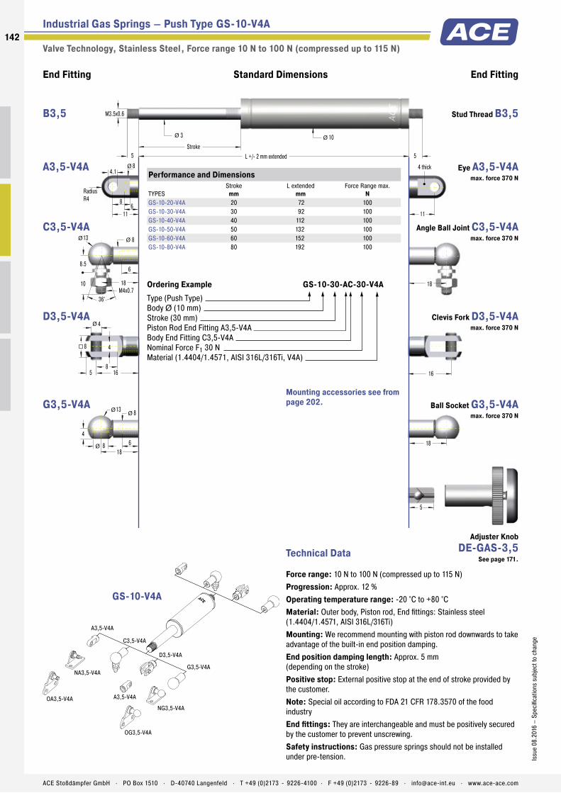
Industrial Gas Springs – Push Type GS-10-V4A
Valve Technology, Stainless Steel , Force range 10 N to 100 N (compressed up to 115 N)
16
4
8
4
5 16
8
Ø
18
18
4
138
68
18
ØØ
Ø
18
M4x0.7
8.5
13 8
6
10
36°
Ø Ø
11
8
11
4.1
6
8Ø
Radius
R4
4 thick
End Fitting End FittingStandard Dimensions
5
M3.5x0.6
5 L +/- 2 mm extended
3
Stroke
5
10Ø Ø
A3,5-V4A
C3,5-V4A
NA3,5-V4A
A3,5-V4A
NG3,5-V4A
OG3,5-V4A
OA3,5-V4A
D3,5-V4A
G3,5-V4A
Technical Data
Force range: 10 N to 100 N (compressed up to 115 N)
Progression: Approx. 12 %
Operating temperature range: -20 °C to +80 °C
Material: Outer body, Piston rod, End fittings: Stainless steel (1.4404/1.4571, AISI 316L/316Ti)
Mounting: We recommend mounting with piston rod downwards to take advantage of the built-in end position damping.
End position damping length: Approx. 5 mm (depending on the stroke)
Positive stop: External positive stop at the end of stroke provided by the customer.
Note: Special oil according to FDA 21 CFR 178.3570 of the food industry
End fittings: They are interchangeable and must be positively secured by the customer to prevent unscrewing.
Safety instructions: Gas pressure springs should not be installed under pre-tension.
Performance and Dimensions
TYPES
Stroke
mm
L extended
mm
Force Range max.
N
GS-10-20-V4A 20 72 100
GS-10-30-V4A 30 92 100
GS-10-40-V4A 40 112 100
GS-10-50-V4A 50 132 100
GS-10-60-V4A 60 152 100
GS-10-80-V4A 80 192 100
Ordering Example GS-10-30-AC-30-V4A
Type (Push Type)
Body Ø (10 mm)
Stroke (30 mm)
Piston Rod End Fitting A3,5-V4A
Body End Fitting C3,5-V4A
Nominal Force F1 30 N
Material (1.4404/1.4571, AISI 316L/316Ti, V4A)
GS-10-V4A
Mounting accessories see from
page 202.
Stud Thread B3,5 B3,5
Eye A3,5-V4A
max. force 370 N
A3,5-V4A
Angle Ball Joint C3,5-V4A
max. force 370 N
C3,5-V4A
Clevis Fork D3,5-V4A
max. force 370 N
D3,5-V4A
Ball Socket G3,5-V4A
max. force 370 N
G3,5-V4A
Adjuster Knob
DE-GAS-3,5
See page 171.
142
Issu
e 0
8.2
016
– S
peci
ficat
ion
s su
bje
ct t
o c
han
ge
ACE Stoßdämpfer GmbH . PO Box 1510 . D-40740 Langenfeld . T +49 (0)2173 - 9226-4100 . F +49 (0)2173 - 9226-89 . [email protected] . www.ace-ace.com

Industrial Gas Springs – Push Type GS-12-V4A
Valve Technology, Stainless Steel , Force range 15 N to 180 N (compressed up to 212 N)
16
4
8
4
5 16
8
Ø
18
18
4
138
68
18
ØØ
Ø
18
M4x0.7
8.5
13 8
6
10
36°
Ø Ø
11
8
11
4.1
6
8Ø
Radius
R4
4 thick
End Fitting End FittingStandard Dimensions
5
M3.5x0.6
5 L +/- 2 mm extended
4
Stroke
5
12Ø Ø
A3,5-V4A
C3,5-V4A
NA3,5-V4A
A3,5-V4A
NG3,5-V4A
OG3,5-V4A
OA3,5-V4A
D3,5-V4A
G3,5-V4A
Technical Data
Force range: 15 N to 180 N (compressed up to 212 N)
Progression: Approx. 18 %
Operating temperature range: -20 °C to +80 °C
Material: Outer body, Piston rod, End fittings: Stainless steel (1.4404/1.4571, AISI 316L/316Ti)
Mounting: We recommend mounting with piston rod downwards to take advantage of the built-in end position damping.
End position damping length: Approx. 10 mm (depending on the stroke)
Positive stop: External positive stop at the end of stroke provided by the customer.
Note: Special oil according to FDA 21 CFR 178.3570 of the food industry
End fittings: They are interchangeable and must be positively secured by the customer to prevent unscrewing.
Safety instructions: Gas pressure springs should not be installed under pre-tension.
Performance and Dimensions
TYPES
Stroke
mm
L extended
mm
Force Range max.
N
GS-12-20-V4A 20 72 180
GS-12-30-V4A 30 92 180
GS-12-40-V4A 40 112 180
GS-12-50-V4A 50 132 180
GS-12-60-V4A 60 152 180
GS-12-80-V4A 80 192 150
GS-12-100-V4A 100 232 150
GS-12-120-V4A 120 272 120
GS-12-150-V4A 150 332 100
Ordering Example GS-12-100-AA-30-V4A
Type (Push Type)
Body Ø (12 mm)
Stroke (100 mm)
Piston Rod End Fitting A3,5-V4A
Body End Fitting A3,5-V4A
Nominal Force F1 30 N
Material (1.4404/1.4571, AISI 316L/316Ti, V4A)
GS-12-V4A
Mounting accessories see from
page 202.
Stud Thread B3,5 B3,5
Eye A3,5-V4A
max. force 370 N
A3,5-V4A
Angle Ball Joint C3,5-V4A
max. force 370 N
C3,5-V4A
Clevis Fork D3,5-V4A
max. force 370 N
D3,5-V4A
Ball Socket G3,5-V4A
max. force 370 N
G3,5-V4A
Adjuster Knob
DE-GAS-3,5
See page 171.
143
Issu
e 0
8.2
016
– S
peci
ficat
ion
s su
bje
ct t
o c
han
ge
ACE Stoßdämpfer GmbH . PO Box 1510 . D-40740 Langenfeld . T +49 (0)2173 - 9226-4100 . F +49 (0)2173 - 9226-89 . [email protected] . www.ace-ace.com

Industrial Gas Springs – Push Type GS-15-VA
Valve Technology, Stainless Steel , Force range 40 N to 400 N (compressed up to 535 N)
End Fitting End FittingStandard Dimensions
7
22
22
4.5
138
128
M5x0.8
22
7 L+/- 2 mm extended
6
Stroke
7
15.6
L = Stroke + 20
19
ØØ
Ø
Ø Ø
27
Ø
22
M5x0.8
8
13 8
12
10
36°
Ø Ø
20
16
24° 10 5
8
12
13
4.5
1027
12
ØØ
Ø
5
10
5
6 20
10
Ø
14
9
16
6.1
8
10Ø
Radius
R5
6 thick
A5-VA
MA5-V4A
NG5-V4A
NA5-V4A
OG5-V4A
OA5-V4A
PA5-V4A
PG5-V4A
C5-VAD5-VA
E5-VAG5-VA
Technical Data
Force range: 40 N to 400 N (compressed up to 535 N)
Progression: Approx. 34 %
Operating temperature range: -20 °C to +80 °C
Material: Outer body, Piston rod, End fittings: Stainless steel (1.4301/1.4305, AISI 304/303)
Mounting: We recommend mounting with piston rod downwards to take advantage of the built-in end position damping.
End position damping length: Approx. 20 mm (depending on the stroke)
Positive stop: External positive stop at the end of stroke provided by the customer.
Note: Special oil according to FDA 21 CFR 178.3570 of the food industry
End fittings: They are interchangeable and must be positively secured by the customer to prevent unscrewing.
Safety instructions: Gas pressure springs should not be installed under pre-tension.
Performance and Dimensions
TYPES
Stroke
mm
L extended
mm
Force Range max.
N
GS-15-20-VA 20 74 400
GS-15-40-VA 40 114 400
GS-15-50-VA 50 134 400
GS-15-60-VA 60 154 400
GS-15-80-VA 80 194 400
GS-15-100-VA 100 234 400
GS-15-120-VA 120 274 400
GS-15-150-VA 150 334 400
Ordering Example GS-15-150-AC-150-VA
Type (Push Type)
Body Ø (15.6 mm)
Stroke (150 mm)
Piston Rod End Fitting A5-VA
Body End Fitting C5-VA
Nominal Force F1 150 N
Material (1.4301/1.4305, AISI 304/303, VA)
GS-15-VA
Mounting accessories see from
page 202.
Stud Thread B5 B5
Eye A5-VA
max. force 490 N
A5-VA
Angle Ball Joint C5-VA
max. force 430 N
C5-VA
Clevis Fork D5-VA
max. force 490 N
D5-VA
Swivel Eye E5-VA
max. force 490 N
E5-VA
Ball Socket G5-VA
max. force 430 N
G5-VA
Rod Shroud
W5-15-VA
Adjuster Knob
DE-GAS-5
See page 171.
144
Issu
e 0
8.2
016
– S
peci
ficat
ion
s su
bje
ct t
o c
han
ge
ACE Stoßdämpfer GmbH . PO Box 1510 . D-40740 Langenfeld . T +49 (0)2173 - 9226-4100 . F +49 (0)2173 - 9226-89 . [email protected] . www.ace-ace.com

Industrial Gas Springs – Push Type GS-19-VA
Valve Technology, Stainless Steel , Force range 50 N to 700 N (compressed up to 930 N)
End Fitting End FittingStandard Dimensions
10
30
30
6
2013
1513
M8x1.25
30
10 L+/- 2 mm extended
8
Stroke
10
19
L = Stroke + 30
23
ØØ
Ø
Ø Ø
36
Ø
30
M8x1.25
12
20 13
15
16,5
36°
Ø Ø
32
19
24° 12 8
12
16
16
6
1236
13
ØØ
Ø
8
16
8
10 32
16
Ø
22
11.5
19
8.1
10
14Ø
Radius
R7
10 thick
A8-VA
MA8-V4A
MA8-V4A
NG8-V4A
NA8-V4A
OG8-V4A
OA8-V4A
PA8-V4A
PG8-V4A
C8-VAD8-VA
E8-VAG8-VA
Technical Data
Force range: 50 N to 700 N (compressed up to 930 N)
Progression: Approx. 33 %
Operating temperature range: -20 °C to +80 °C
Material: Outer body, Piston rod, End fittings: Stainless steel (1.4301/1.4305, AISI 304/303)
Mounting: We recommend mounting with piston rod downwards to take advantage of the built-in end position damping.
End position damping length: Approx. 20 mm (depending on the stroke)
Positive stop: External positive stop at the end of stroke provided by the customer.
Note: Special oil according to FDA 21 CFR 178.3570 of the food industry
End fittings: They are interchangeable and must be positively secured by the customer to prevent unscrewing.
Safety instructions: Gas pressure springs should not be installed under pre-tension.
Performance and Dimensions
TYPES
Stroke
mm
L extended
mm
Force Range max.
N
GS-19-50-VA 50 164 700
GS-19-100-VA 100 264 700
GS-19-150-VA 150 364 700
GS-19-200-VA 200 464 700
GS-19-250-VA 250 564 700
GS-19-300-VA 300 664 700
Ordering Example GS-19-150-AC-600-VA
Type (Push Type)
Body Ø (19 mm)
Stroke (150 mm)
Piston Rod End Fitting A8-VA
Body End Fitting C8-VA
Nominal Force F1 600 N
Material (1.4301/1.4305, AISI 304/303, VA)
GS-19-VA
Mounting accessories see from
page 202.
Stud Thread B8 B8
Eye A8-VA
max. force 1,560 N
A8-VA
Angle Ball Joint C8-VA
max. force 1,140 N
C8-VA
Clevis Fork D8-VA
max. force 1,560 N
D8-VA
Swivel Eye E8-VA
max. force 1,560 N
E8-VA
Ball Socket G8-VA
max. force 1,140 N
G8-VA
Rod Shroud
W8-19-VA
Adjuster Knob
DE-GAS-8
See page 171.
145
Issu
e 0
8.2
016
– S
peci
ficat
ion
s su
bje
ct t
o c
han
ge
ACE Stoßdämpfer GmbH . PO Box 1510 . D-40740 Langenfeld . T +49 (0)2173 - 9226-4100 . F +49 (0)2173 - 9226-89 . [email protected] . www.ace-ace.com
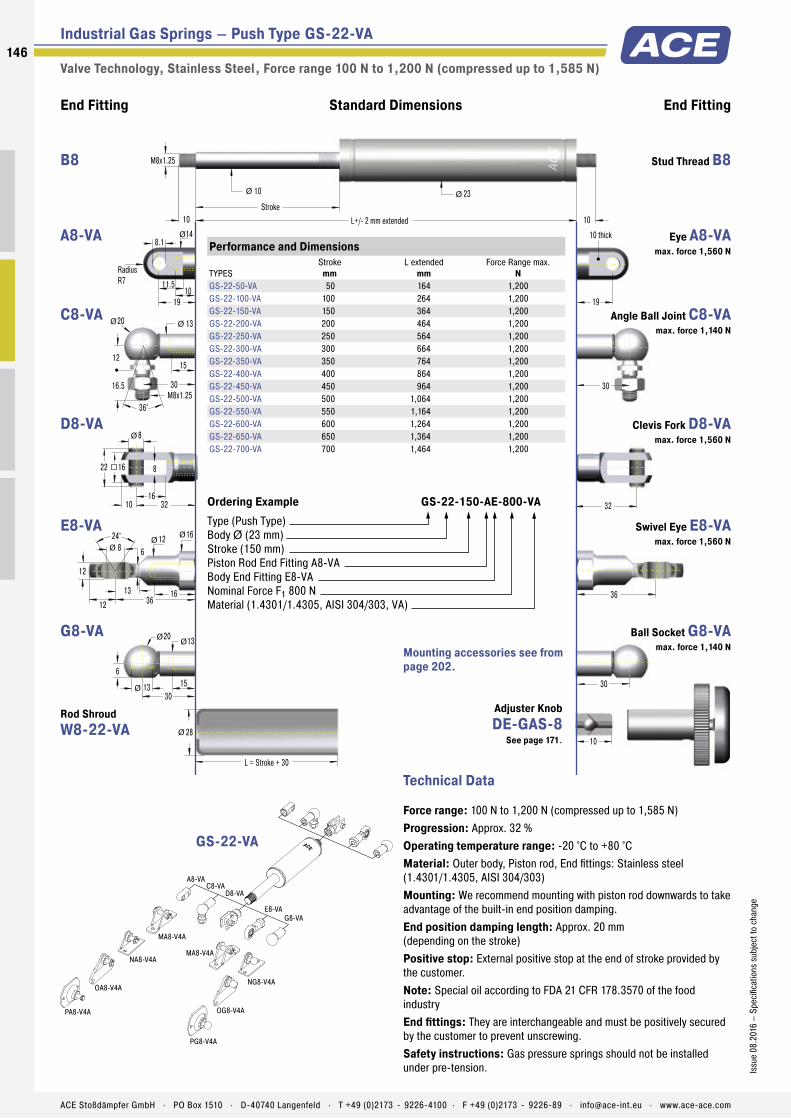
Industrial Gas Springs – Push Type GS-22-VA
Valve Technology, Stainless Steel , Force range 100 N to 1,200 N (compressed up to 1,585 N)
End Fitting End FittingStandard Dimensions
10
30
30
6
2013
1513
M8x1.25
30
10 L+/- 2 mm extended
10
Stroke
10
23
L = Stroke + 30
28
ØØ
Ø
Ø Ø
36
Ø
30
M8x1.25
12
20 13
15
16.5
36°
Ø Ø
32
19
24° 12 8
12
16
16
6
1236
13
ØØ
Ø
8
16
8
10 32
16
Ø
22
11.5
19
8.1
10
14Ø
Radius
R7
10 thick
A8-VA
MA8-V4A
MA8-V4A
NG8-V4A
NA8-V4A
OG8-V4A
OA8-V4A
PA8-V4A
PG8-V4A
C8-VAD8-VA
E8-VAG8-VA
Technical Data
Force range: 100 N to 1,200 N (compressed up to 1,585 N)
Progression: Approx. 32 %
Operating temperature range: -20 °C to +80 °C
Material: Outer body, Piston rod, End fittings: Stainless steel (1.4301/1.4305, AISI 304/303)
Mounting: We recommend mounting with piston rod downwards to take advantage of the built-in end position damping.
End position damping length: Approx. 20 mm (depending on the stroke)
Positive stop: External positive stop at the end of stroke provided by the customer.
Note: Special oil according to FDA 21 CFR 178.3570 of the food industry
End fittings: They are interchangeable and must be positively secured by the customer to prevent unscrewing.
Safety instructions: Gas pressure springs should not be installed under pre-tension.
Performance and Dimensions
TYPES
Stroke
mm
L extended
mm
Force Range max.
N
GS-22-50-VA 50 164 1,200
GS-22-100-VA 100 264 1,200
GS-22-150-VA 150 364 1,200
GS-22-200-VA 200 464 1,200
GS-22-250-VA 250 564 1,200
GS-22-300-VA 300 664 1,200
GS-22-350-VA 350 764 1,200
GS-22-400-VA 400 864 1,200
GS-22-450-VA 450 964 1,200
GS-22-500-VA 500 1,064 1,200
GS-22-550-VA 550 1,164 1,200
GS-22-600-VA 600 1,264 1,200
GS-22-650-VA 650 1,364 1,200
GS-22-700-VA 700 1,464 1,200
Ordering Example GS-22-150-AE-800-VA
Type (Push Type)
Body Ø (23 mm)
Stroke (150 mm)
Piston Rod End Fitting A8-VA
Body End Fitting E8-VA
Nominal Force F1 800 N
Material (1.4301/1.4305, AISI 304/303, VA)
GS-22-VA
Mounting accessories see from
page 202.
Stud Thread B8 B8
Eye A8-VA
max. force 1,560 N
A8-VA
Angle Ball Joint C8-VA
max. force 1,140 N
C8-VA
Clevis Fork D8-VA
max. force 1,560 N
D8-VA
Swivel Eye E8-VA
max. force 1,560 N
E8-VA
Ball Socket G8-VA
max. force 1,140 N
G8-VA
Rod Shroud
W8-22-VA
Adjuster Knob
DE-GAS-8
See page 171.
146
Issu
e 0
8.2
016
– S
peci
ficat
ion
s su
bje
ct t
o c
han
ge
ACE Stoßdämpfer GmbH . PO Box 1510 . D-40740 Langenfeld . T +49 (0)2173 - 9226-4100 . F +49 (0)2173 - 9226-89 . [email protected] . www.ace-ace.com

Industrial Gas Springs – Push Type GS-28-VA
Valve Technology, Stainless Steel , Force range 150 N to 2,500 N (compressed up to 3,800 N)
End Fitting End FittingStandard Dimensions
12
M10x1.5
35
12 L+/- 2 mm extended
14
Stroke
12
28
L = Stroke + 40
32
Ø Ø
43
Ø
35
M10x1.5
16
24 16
18
20
36°
Ø Ø
40
27
24° 15 10
14
18
19
7
1443
16
ØØ
Ø
10
20
10
12 40
20
Ø
26.5
15
27
8.1
15
18Ø
Radius
R9
10 thick
A10-VA
C10-VA
D10-VA
E10-VA
MA10-V4A
Technical Data
Force range: 150 N to 2,500 N (compressed up to 3,800 N)
Progression: Approx. 52 %
Operating temperature range: -20 °C to +80 °C
Material: Outer body, Piston rod, End fittings: Stainless steel (1.4301/1.4305, AISI 304/303)
Mounting: We recommend mounting with piston rod downwards to take advantage of the built-in end position damping.
End position damping length: Approx. 20 mm (depending on the stroke)
Positive stop: External positive stop at the end of stroke provided by the customer.
Note: Special oil according to FDA 21 CFR 178.3570 of the food industry
End fittings: They are interchangeable and must be positively secured by the customer to prevent unscrewing.
Safety instructions: Gas pressure springs should not be installed under pre-tension.
Performance and Dimensions
TYPES
Stroke
mm
L extended
mm
Force Range max.
N
GS-28-100-VA 100 262 2,500
GS-28-150-VA 150 362 2,500
GS-28-200-VA 200 462 2,500
GS-28-250-VA 250 562 2,500
GS-28-300-VA 300 662 2,500
GS-28-350-VA 350 762 2,500
GS-28-400-VA 400 862 2,500
GS-28-450-VA 450 962 2,500
GS-28-500-VA 500 1,062 2,500
GS-28-550-VA 550 1,162 2,500
GS-28-600-VA 600 1,262 2,500
GS-28-650-VA 650 1,362 2,500
Ordering Example GS-28-150-EE-1200-VA
Type (Push Type)
Body Ø (28 mm)
Stroke (150 mm)
Piston Rod End Fitting E10-VA
Body End Fitting E10-VA
Nominal Force F1 1200 N
Material (1.4301/1.4305, AISI 304/303, VA)
GS-28-VA
Mounting accessories see from
page 202.
Stud Thread B10 B10
Eye A10-VA
max. force 3,800 N
A10-VA
Angle Ball Joint C10-VA
max. force 1,750 N
C10-VA
Clevis Fork D10-VA
max. force 3,800 N
D10-VA
Swivel Eye E10-VA
max. force 3,800 N
E10-VA
Rod Shroud
W10-28-VA
Adjuster Knob
DE-GAS-10
See page 171.
147
Issu
e 0
8.2
016
– S
peci
ficat
ion
s su
bje
ct t
o c
han
ge
ACE Stoßdämpfer GmbH . PO Box 1510 . D-40740 Langenfeld . T +49 (0)2173 - 9226-4100 . F +49 (0)2173 - 9226-89 . [email protected] . www.ace-ace.com
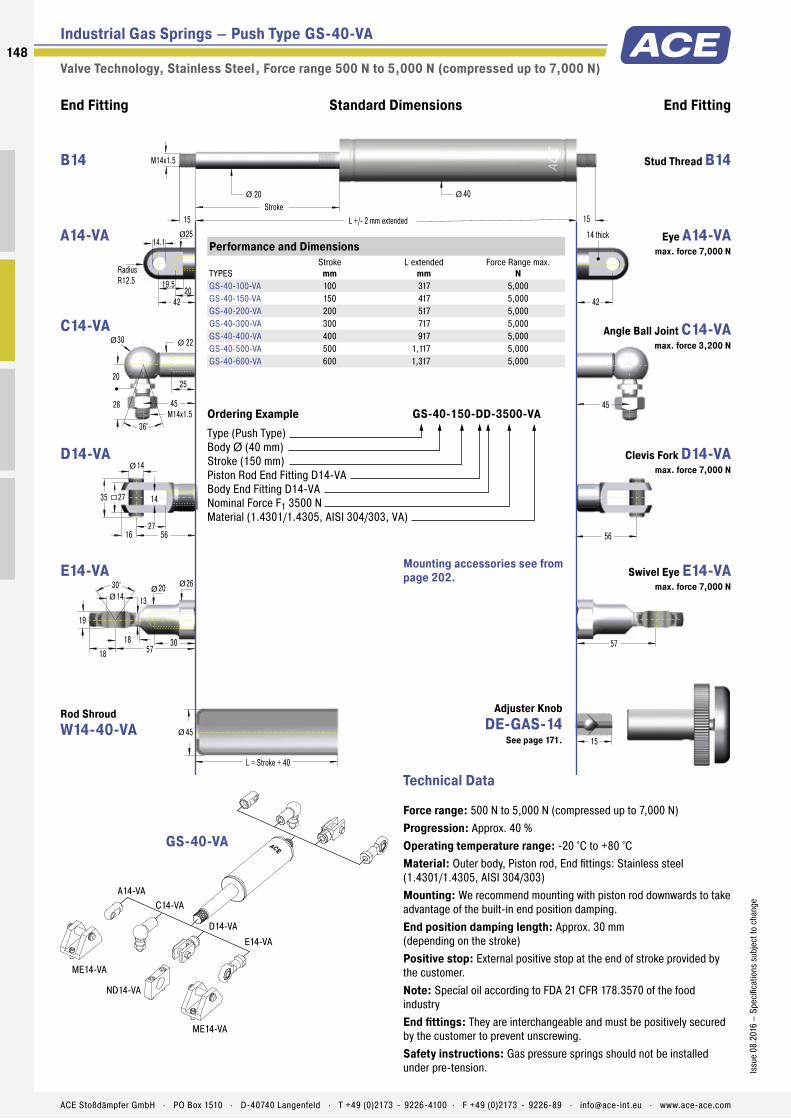
Industrial Gas Springs – Push Type GS-40-VA
Valve Technology, Stainless Steel , Force range 500 N to 5,000 N (compressed up to 7,000 N)
End Fitting End FittingStandard Dimensions
15
M14x1.5
45
15 L +/- 2 mm extended
20
Stroke
15
40
L = Stroke + 40
45
Ø Ø
57
Ø
45
M14x1.5
20
30 22
25
28
36°
Ø Ø
56
42
30° 20 14
19
30
26
13
1857
18
ØØ
Ø
14
27
14
16 56
27
Ø
35
19.5
42
14.1
20
25Ø
Radius
R12.5
14 thick
A14-VA
C14-VA
D14-VA
E14-VA
ME14-VA
ME14-VA
ND14-VA
Technical Data
Force range: 500 N to 5,000 N (compressed up to 7,000 N)
Progression: Approx. 40 %
Operating temperature range: -20 °C to +80 °C
Material: Outer body, Piston rod, End fittings: Stainless steel (1.4301/1.4305, AISI 304/303)
Mounting: We recommend mounting with piston rod downwards to take advantage of the built-in end position damping.
End position damping length: Approx. 30 mm (depending on the stroke)
Positive stop: External positive stop at the end of stroke provided by the customer.
Note: Special oil according to FDA 21 CFR 178.3570 of the food industry
End fittings: They are interchangeable and must be positively secured by the customer to prevent unscrewing.
Safety instructions: Gas pressure springs should not be installed under pre-tension.
Performance and Dimensions
TYPES
Stroke
mm
L extended
mm
Force Range max.
N
GS-40-100-VA 100 317 5,000
GS-40-150-VA 150 417 5,000
GS-40-200-VA 200 517 5,000
GS-40-300-VA 300 717 5,000
GS-40-400-VA 400 917 5,000
GS-40-500-VA 500 1,117 5,000
GS-40-600-VA 600 1,317 5,000
Ordering Example GS-40-150-DD-3500-VA
Type (Push Type)
Body Ø (40 mm)
Stroke (150 mm)
Piston Rod End Fitting D14-VA
Body End Fitting D14-VA
Nominal Force F1 3500 N
Material (1.4301/1.4305, AISI 304/303, VA)
GS-40-VA
Mounting accessories see from
page 202.
Stud Thread B14 B14
Eye A14-VA
max. force 7,000 N
A14-VA
Angle Ball Joint C14-VA
max. force 3,200 N
C14-VA
Clevis Fork D14-VA
max. force 7,000 N
D14-VA
Swivel Eye E14-VA
max. force 7,000 N
E14-VA
Rod Shroud
W14-40-VA
Adjuster Knob
DE-GAS-14
See page 171.
148
Issu
e 0
8.2
016
– S
peci
ficat
ion
s su
bje
ct t
o c
han
ge
ACE Stoßdämpfer GmbH . PO Box 1510 . D-40740 Langenfeld . T +49 (0)2173 - 9226-4100 . F +49 (0)2173 - 9226-89 . [email protected] . www.ace-ace.com

Stainless Steel Gas Springs – Push Type (V4A)
Performance
TYPES
Stroke
mm
L extended
mm
Dimensions
see Page
GS-15-20-V4A 20 74 144
GS-15-40-V4A 40 114 144
GS-15-50-V4A 50 134 144
GS-15-60-V4A 60 154 144
GS-15-80-V4A 80 194 144
GS-15-100-V4A 100 234 144
GS-15-120-V4A 120 274 144
GS-15-150-V4A 150 334 144
GS-19-50-V4A 50 164 145
GS-19-100-V4A 100 264 145
GS-19-150-V4A 150 364 145
GS-19-200-V4A 200 464 145
GS-19-250-V4A 250 564 145
GS-19-300-V4A 300 664 145
GS-22-50-V4A 50 164 146
GS-22-100-V4A 100 264 146
GS-22-150-V4A 150 364 146
GS-22-200-V4A 200 464 146
GS-22-250-V4A 250 564 146
GS-22-300-V4A 300 664 146
GS-22-350-V4A 350 764 146
GS-22-400-V4A 400 864 146
GS-22-450-V4A 450 964 146
GS-22-500-V4A 500 1,064 146
GS-22-550-V4A 550 1,164 146
GS-22-600-V4A 600 1,264 146
GS-22-650-V4A 650 1,364 146
GS-22-700-V4A 700 1,464 146
GS-28-100-V4A 100 262 147
GS-28-150-V4A 150 362 147
GS-28-200-V4A 200 462 147
GS-28-250-V4A 250 562 147
GS-28-300-V4A 300 662 147
GS-28-350-V4A 350 762 147
GS-28-400-V4A 400 862 147
GS-28-450-V4A 450 962 147
GS-28-500-V4A 500 1,062 147
GS-28-550-V4A 550 1,162 147
GS-28-600-V4A 600 1,262 147
GS-28-650-V4A 650 1,362 147
GS-40-100-V4A 100 317 148
GS-40-150-V4A 150 417 148
GS-40-200-V4A 200 517 148
GS-40-300-V4A 300 717 148
GS-40-400-V4A 400 917 148
GS-40-500-V4A 500 1,117 148
GS-40-600-V4A 600 1,317 148
Further Stainless Steel Gas Springs (Push Type), V4A
Further Stainless Steel Accessories, V4A
End Fittings
TYPES
Dimensions
see Page
A5-V4A 204
C5-V4A 204
D5-V4A 204
E5-V4A 204
G5-V4A 204
A8-V4A 205
C8-V4A 205
D8-V4A 205
E8-V4A 205
G8-V4A 06
End Fittings
TYPES
Dimensions
see Page
A10-V4A 206
C10-V4A 206
D10-V4A 206
E10-V4A 206
A14-V4A 206
C14-V4A 206
D14-V4A 206
E14-V4A 206
149
Issu
e 0
8.2
016
– S
peci
ficat
ion
s su
bje
ct t
o c
han
ge
ACE Stoßdämpfer GmbH . PO Box 1510 . D-40740 Langenfeld . T +49 (0)2173 - 9226-4100 . F +49 (0)2173 - 9226-89 . [email protected] . www.ace-ace.com

Metering Orifice for Controlled Velocities
Filled with High Pressure Nitrogen Gas
Valve
Oil Zone for End Position Damping
Seals
Piston Rod
Main Bearing
Outer Body
Thread for End Fittings
Grease Chamber for Low Breakaway Force
Body A
Body B
Technical Data
Cover two differing force ranges: Tandem push type gas springs by ACE are maintenance-free and ready-to-install with two pressure tubes with different extension forces and progression curves. With this type of gas spring you cover the different force ranges between the start and end of an application. These force ranges are adjusted and compliment each other, designed individually for the relevant application by the free of charge ACE calculation service, then are specifi cally manufactured adjusted precisely to the required dynamics of the application.
The customer specifi c systems, for which there are many fi tting parts, are specifi cally suitable for heavy loads with large opening angle and can also be delivered in stainless steel versions.
Tandem push type gas springs from ACE are used in industrial applications such as in mechanical engineering, in the automobile, electronics and furniture industries, but also in medical technology as well as for service hatches.
GST-40 TandemIndustrial Gas Springs – Push Type
Optimised dual force for heavy fl aps and
wide angle applications
Industrial Gas Springs – Push Type
Valve Technology
Force range: 300 N to 5,000 N
Piston rod diameter: Ø 20 mm
Progression: According to calculation relating to your application.
Lifetime: Approx. 10,000 m
Operating temperature range: -20 °C to +80 °C
Material: Outer body, End fi ttings: Zinc plated steel; Piston rod: Steel with wear-resistant coating
Operating fl uid: Nitrogen gas and oil
Mounting: In any position. Please adopt the mounting points determined by ACE.
End position damping length: Application-specifi c end position damping and extension speed.
Positive stop: External positive stop at the end of stroke provided by the customer.
Application fi eld: Hoods, Shutters, Machine housing, Conveyor systems
Note: These gas springs are tailored to the relevant application and are therefore not available ex stock.
End fi ttings: They are interchangeable and must be positively secured by the customer to prevent unscrewing.
On request: Special oils and other special options. Alternative accessories. Material 1.4301/1.4305, AISI 304/303 (V2A) and 1.4404/1.4571, AISI 316L/316Ti (V4A).
150
Issu
e 0
8.2
016
– S
pec
ifi ca
tio
ns s
ubje
ct t
o c
hang
e
ACE Stoßdämpfer GmbH . PO Box 1510 . D-40740 Langenfeld . T +49 (0)2173 - 9226-4100 . F +49 (0)2173 - 9226-89 . [email protected] . www.ace-ace.com

Industrial Gas Springs – Push Type GST-40
Valve Technology , Force range 300 N to 5,000 N
End Fitting End FittingStandard Dimensions
56
14
27
14
16 56
27
15
M14x1.5
25
21
40 L +/- 2 mm extended
14.1
Radius
R12.5
14 thick
40
14 thick
21
Ø
Ø
57
Ø Ø
15
14.1
30° 20 14
19
30
26
13
1857
18
ØØ
Ø
Body AØ 40
Body BØ 40 Stroke BStroke A
20Ø
A14
ME14
D14
E14
ND14
ME14
Technical Data
Progression: According to calculation relating to your application.
Operating temperature range: -20 °C to +80 °C
Material: Outer body, End fi ttings: Zinc plated steel; Piston rod: Steel with wear-resistant coating
Mounting: In any position. Please adopt the mounting points deter-mined by ACE.
End position damping length: Application-specifi c end position damping and extension speed.
Positive stop: External positive stop at the end of stroke provided by the customer.
Note: These gas springs are tailored to the relevant application and are therefore not available ex stock.
End fi ttings: They are interchangeable and must be positively secured by the customer to prevent unscrewing.
Performance and Dimensions
TYPES
Stroke A
mm
Stroke B
mm
L extended
mm
Force Range max.
N
GST-40-50-100 50 100 485 5,000
GST-40-50-150 50 150 585 5,000
GST-40-50-200 50 200 685 5,000
GST-40-70-250 70 250 825 5,000
GST-40-70-300 70 300 925 5,000
GST-40-70-350 70 350 1,025 5,000
GST-40-70-400 70 400 1,125 5,000
Ordering Example GST-40-50-150-AD-900N-2500N
Type (Tandem Gas Spring)
Body Ø (40 mm)
Stroke A (50 mm)
Stroke B (150 mm)
Body A End Fitting, A14
Body B End Fitting, D14
Nominal Force Body A, 900 N
Nominal Force Body B, 2500 N
GST-40
Mounting accessories see from
page 194.
Eye A14
max. force 10,000 N
A14
Stud Thread B14 B14
Clevis Fork D14
max. force 10,000 N
D14
Swivel Eye E14
max. force 10,000 N
E14
151
Issu
e 0
8.2
016
– S
pec
ifi ca
tio
ns s
ubje
ct t
o c
hang
e
ACE Stoßdämpfer GmbH . PO Box 1510 . D-40740 Langenfeld . T +49 (0)2173 - 9226-4100 . F +49 (0)2173 - 9226-89 . [email protected] . www.ace-ace.com

Application Examples
Industrial Gas Springs – Push Type
GS-12
Safe opening and closingACE industrial gas springs (push type) protect samples in an incubator, which is used for chemical and biochemical applications. The plexiglass hood, under which may be found valuable laboratory goods, is securely held open by two maintenance-free, ready-to-install ACE industrial gas springs (push type) of the type GS-12-60-AA-X . With an end-position damping of 5 mm and an extension force of 10 to 180 N, they help to handle the forces generated. The hood is always easily opened and remains in this position. It also remains securely shut when the incubator is in operation.
Very small ACE industrial gas springs (push type) enable careful opening
and closing movements of a mini-incubator hood, under which may be found
laboratory products
GFL Gesellschaft für Labortechnik mbH, 30938 Burgwedel, Germany
GS-19
Doors open and close safelyACE industrial gas springs make opening and closing doors of rescue helicopters easier. The maintenance-free, sealed systems are installed in the access doors of helicopters of the type EC 135. There, they allow the crew to enter or exit the helicopter quickly, thus contributing to enhanced safety. The GS-19-300-CC gas springs provide a defi ned retraction speed and secure engagement of the door lock. The integrated end position damper allows gentle closing of the door and saves wear and tear on the valuable, lightweight material.
Industrial gas springs: For safe entry and exit
152
Issu
e 0
8.2
016
– S
pec
ifi ca
tio
ns s
ubje
ct t
o c
hang
e
ACE Stoßdämpfer GmbH . PO Box 1510 . D-40740 Langenfeld . T +49 (0)2173 - 9226-4100 . F +49 (0)2173 - 9226-89 . [email protected] . www.ace-ace.com

Industrial Gas Springs – Push Type
Application Examples
GS-22-VA
Made-to-measure stainless steel gas springsA special hygiene and toilet chair, designed for children and young people with disabilities, must be fi rmly lockable in the sit and tilt positions. The practical aid thereby provided for relatives and carers can be attributed to two lockable ACE industrial gas springs (push type) which were especially developed and manufactured for this application and operate on the basis of the so-called tilt-in-space function. This allows the chair to be tilted forwards and backwards and provides signifi cantly more convenience for users and patients. In order to meet all hygiene requirements, the gas springs are constructed in stainless steel.
With inclination angles of 15 degrees to the front and rear, the ACE stainless
steel gas springs facilitate the work of nurses
Rifton Equipment, Rifton, New York 12471, USA
GST-40
Tandemly-operated large fl aps securely under controlUnderground distribution systems are visually advantageous. To facilitate their servicing, the heavy covers of the often large supply systems are brought back to the surface with the help of ACE industrial tandem gas springs (push type). This is quite easily achieved thanks to the use of two pressure pipes, the result of which is two different force ranges. This means fi tters must not endure laborious bending and a downward passage into the system of channels. In addition to these advantages, the springs benefi t from their long service life and their capacity to be used, as stainless steel variants, in even the most hygienically-sensitive areas.
ACE industrial tandem gas springs (push type) enable easy maintenance
of supply boxes by making the heavy fl aps easier to operate
Langmatz GmbH, 82467 Garmisch-Partenkirchen, Germany
153
Issu
e 0
8.2
016
– S
pec
ifi ca
tio
ns s
ubje
ct t
o c
hang
e
ACE Stoßdämpfer GmbH . PO Box 1510 . D-40740 Langenfeld . T +49 (0)2173 - 9226-4100 . F +49 (0)2173 - 9226-89 . [email protected] . www.ace-ace.com