Embed Size (px)
Citation preview
L3
GTT AND APTH, J, AND HJ GH
Serial #
Installation Date
2 YEAR WARRANTYTHIS PRODUCT IS TO BE INSTALLED AND SERVICED BY A TRAINED DOOR SYSTEMS TECHNICIAN ONLY.Operators are shipped in C2 operating mode. Visit www.liftmaster.com to locate a professional installing dealer in your area.
CONTACT INFORMATION
INDUSTRIAL DUTYCOMMERCIAL DOOR OPERATOR
INSTALLATION MANUAL
Security+ 2.0TM

TABLE OF CONTENTSSAFETY INFORMATION 3
TROLLEY OPERATORS 4-12 Carton Inventory . . . . . . . . . . . . . . . . . . . . . . . . . . . . . . . 4 Operator Specifications . . . . . . . . . . . . . . . . . . . . . . . . .4-5 Maximum Door Area . . . . . . . . . . . . . . . . . . . . . . . . . . . . 5 Weights and Dimensions . . . . . . . . . . . . . . . . . . . . . . . . . 6 ASSEMBLY. . . . . . . . . . . . . . . . . . . . . . . . . . . . . . . . . . .7-9 Assemble the Operator (Models T and GT) . . . . . . . . . 7 Install the Chain (Models T and GT) . . . . . . . . . . . . . . 8 Assemble the Operator (Model APT) . . . . . . . . . . . . . . 9 TYPICAL INSTALLATION . . . . . . . . . . . . . . . . . . . . . .10-12 Install the Header Bracket . . . . . . . . . . . . . . . . . . . . . 10 Attach the Track to the Header Bracket . . . . . . . . . . . 11 Hang the Operator . . . . . . . . . . . . . . . . . . . . . . . . . . . 11 Attach the Door Arm . . . . . . . . . . . . . . . . . . . . . . . . . 12
HOIST AND JACKSHAFT OPERATORS 13-17 Carton Inventory . . . . . . . . . . . . . . . . . . . . . . . . . . . . . . 13 Operator Specifications . . . . . . . . . . . . . . . . . . . . . . .13-14 Maximum Door Area . . . . . . . . . . . . . . . . . . . . . . . . . . . 14 Weights and Dimensions . . . . . . . . . . . . . . . . . . . . . . . . 15 ASSEMBLY. . . . . . . . . . . . . . . . . . . . . . . . . . . . . . . . . . . 16 Assemble the Operator . . . . . . . . . . . . . . . . . . . . . . . 16 TYPICAL INSTALLATION . . . . . . . . . . . . . . . . . . . . . .16-17 Determine Mounting Location . . . . . . . . . . . . . . . . . . 16 Mounting . . . . . . . . . . . . . . . . . . . . . . . . . . . . . . . . . . 17 Install the Manual Disconnect . . . . . . . . . . . . . . . . . . 17
WIRING 18-19 Power and Ground . . . . . . . . . . . . . . . . . . . . . . . . . . . . . 18 Motor Power Plug Selection . . . . . . . . . . . . . . . . . . . . . 18 Control Station . . . . . . . . . . . . . . . . . . . . . . . . . . . . . . . . 19
ENTRAPMENT PROTECTION 20-22 LiftMaster Monitored Entrapment Protection (LMEP) . . . . . . . . . . . . . . . . . . . . . . . . . . . . . 20 Install the LMEP’s (Optional) . . . . . . . . . . . . . . . . . . . . . 21 Wire the LiftMaster Monitored Entrapment
Protection (LMEP) Devices . . . . . . . . . . . . . . . . . . . . . . 21
ADJUSTMENT 22-23 Limit Adjustment . . . . . . . . . . . . . . . . . . . . . . . . . . . . . . 22 Clutch Adjustment (Belt Drive Model Operators) . . . . . . 23
TESTING 24
MANUAL RELEASE 25-26 Emergency Disconnect System Model GT and T . . . . . . 25 Emergency Disconnect System Model APT . . . . . . . . . . 25
Emergency Disconnect System Model H, GH, J, and HJ . . . . . . . . . . . . . . . . . . . . . . . . . 26
PROGRAMMING 27-34 Introduction to Programming . . . . . . . . . . . . . . . . . . . . 27 Determine and Set Wiring Type . . . . . . . . . . . . . . . . . . . 28 Programming Remote Controls . . . . . . . . . . . . . . . . .29-30 Programming for MyQ® Devices (Optional) . . . . . . . . . . 31 Maintenance Alert System (MAS) . . . . . . . . . . . . . . . . . 31 Open Mid Stop . . . . . . . . . . . . . . . . . . . . . . . . . . . . . . . . 32 Timer-To-Close . . . . . . . . . . . . . . . . . . . . . . . . . . . . .32-33 Car Dealer Mode . . . . . . . . . . . . . . . . . . . . . . . . . . . . . . 33 Maximum Run Timer (MRT) . . . . . . . . . . . . . . . . . . . . . 34 Resetting Factory Defaults - Clearing Memory. . . . . . . . 34
MAINTENANCE 35 Maintenance Schedule . . . . . . . . . . . . . . . . . . . . . . . . . . 35 Life of Operator Feature (Odometer/Cycle Counter). . . . 35 Brake (If Present). . . . . . . . . . . . . . . . . . . . . . . . . . . . . . 35 How to Order Repair Parts. . . . . . . . . . . . . . . . . . . . . . . 35
TROUBLESHOOTING 36-39 Diagnostic Chart. . . . . . . . . . . . . . . . . . . . . . . . . . . . . . . 36 Troubleshooting Guide. . . . . . . . . . . . . . . . . . . . . . . . . . 37 Troubleshooting Error Codes . . . . . . . . . . . . . . . . . . . . . 38 Troubleshooting Radio Functionality . . . . . . . . . . . . . . . 39
WIRING DIAGRAMS 40-41 Logic 5 Single Phase Wiring Diagram . . . . . . . . . . . . . . 40 Logic 5 Three Phase Wiring Diagram . . . . . . . . . . . . . . 41
ACCESSORIES 42
CONTROL CONNECTION DIAGRAM 43
Table of Contents 2

SA
FE
TY
INF
OR
MA
TIO
N
TO REDUCE THE RISK OF SEVERE INJURY OR DEATH:
IMPORTANT INSTALLATION INSTRUCTIONS
1. READ AND FOLLOW ALL INSTALLATION WARNINGS AND INSTRUCTIONS.
2. Install door operator ONLY on properly balanced and lubricated door. An improperly balanced door may NOT reverse when required and could result in SEVERE INJURY or DEATH.
3. ALL repairs to cables, spring assemblies and other hardware MUST be made by a trained door systems technician BEFORE installing operator.
4. Disable ALL locks and remove ALL ropes connected to door BEFORE installing operator to avoid entanglement.
5. Install door operator 8 feet (2.44 m) or more above floor.6. NEVER connect door operator to power source until
instructed to do so.7. NEVER wear watches, rings or loose clothing while installing
or servicing operator. They could be caught in door or operator mechanisms.
8. Install control station: • within sight of the door. • out of reach of children at minimum height of
5 feet (1.5 m). • away from ALL moving parts of the door. 9. Install the control station far enough from the door to
prevent the user from coming in contact with the door while operating the controls.
10. Install the entrapment warning placard on wall next to the control station in a prominent location that is visible from the door.
11. Place manual release/safety reverse test label in plain view on inside of door.
12. Upon completion of installation, test entrapment protection device.
13. SAVE THESE INSTRUCTIONS.
WARNING
WARNING
WARNING WARNING
When you see these Safety Symbols and Signal Words on the following pages, they will alert you to the possibility of serious injury or death if you do not comply with the warnings that accompany them. The hazard may come from something mechanical or from electric shock. Read the warnings carefully.When you see this Signal Word on the following pages, it will alert you to the possibility of damage to your door and/or the door operator if you do not comply with the cautionary statements that accompany it. Read them carefully.
Mechanical
Electrical
IMPORTANT NOTES:• BEFORE attempting to install, operate or maintain the operator,
you must read and fully understand this manual and follow all safety instructions.
• DO NOT attempt repair or service of your commercial door and gate operator unless you are an Authorized Service Technician.
• Operator intended to be installed on a properly balanced door only. Make sure door is properly balanced before installing.
ATTENTION
AVERTISSEMENT AVERTISSEMENT
AVERTISSEMENT
WARNING WARNING
CAUTION
WARNING
WARNING
PRECAUCIÓN ADVERTENCIA
ADVERTENCIA ADVERTENCIA
ATTENTION
AVERTISSEMENT AVERTISSEMENT
AVERTISSEMENT
WARNING
CAUTION
WARNING WARNING
WARNING
PRECAUCIÓN ADVERTENCIA
ADVERTENCIA ADVERTENCIA
ATTENTION
AVERTISSEMENT AVERTISSEMENT
AVERTISSEMENT
WARNING
CAUTION CAUTION
WARNING
WARNING
PRECAUCIÓN ADVERTENCIA
ADVERTENCIA ADVERTENCIA
SAFETY INFORMATION
Safety Information3
TR
OL
LE
Y
4
OPERATOR SPECIFICATIONS
Carton Inventory/Operator Specifi cations - Trolley
TROLLEY OPERATORS
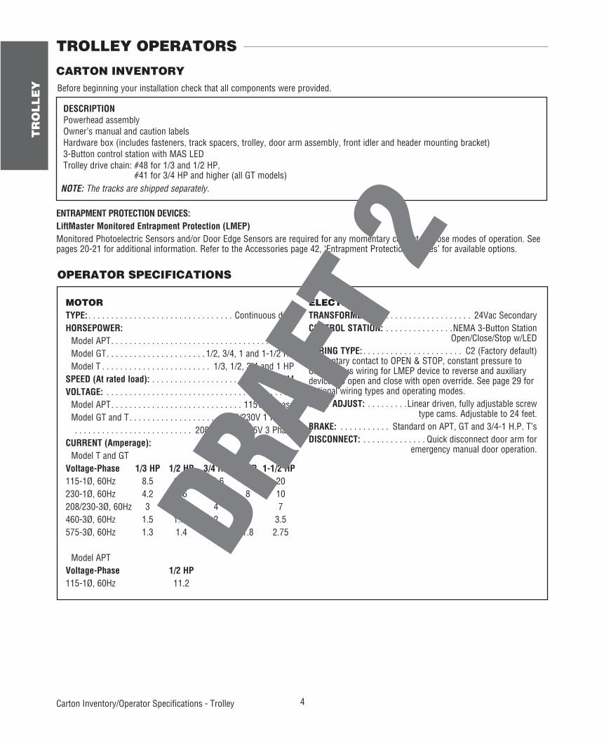
CARTON INVENTORYBefore beginning your installation check that all components were provided.
DESCRIPTION Powerhead assembly Owner’s manual and caution labels Hardware box (includes fasteners, track spacers, trolley, door arm assembly, front idler and header mounting bracket) 3-Button control station with MAS LED Trolley drive chain: #48 for 1/3 and 1/2 HP,
#41 for 3/4 HP and higher (all GT models)NOTE: The tracks are shipped separately.
MOTORTYPE: . . . . . . . . . . . . . . . . . . . . . . . . . . . . . . . . Continuous dutyHORSEPOWER: Model APT . . . . . . . . . . . . . . . . . . . . . . . . . . . . . . . . . . .1/2 HP Model GT . . . . . . . . . . . . . . . . . . . . . . 1/2, 3/4, 1 and 1-1/2 HP Model T . . . . . . . . . . . . . . . . . . . . . . . . 1/3, 1/2, 3/4 and 1 HPSPEED (At rated load): . . . . . . . . . . . . . . . . . . . . . . .1725 RPMVOLTAGE: . . . . . . . . . . . . . . . . . . . . . . . . . . . . . . . . . . . . . . . . . Model APT . . . . . . . . . . . . . . . . . . . . . . . . . . . . . 115V 1 Phase Model GT and T . . . . . . . . . . . . . . . . . . . . . 115/230V 1 Phase, . . . . . . . . . . . . . . . . . . . . . . . . . . 208/230/460/575V 3 PhaseCURRENT (Amperage): Model T and GTVoltage-Phase 1/3 HP 1/2 HP 3/4 HP 1 HP 1-1/2 HP115-1Ø, 60Hz 8.5 11.2 13.6 16 20230-1Ø, 60Hz 4.2 5.6 6.8 8 10208/230-3Ø, 60Hz 3 3.1 4 6 7460-3Ø, 60Hz 1.5 1.75 2 3 3.5575-3Ø, 60Hz 1.3 1.4 1.6 1.8 2.75
Model APTVoltage-Phase 1/2 HP115-1Ø, 60Hz 11.2
ELECTRICALTRANSFORMER: . . . . . . . . . . . . . . . . . . . . . . 24Vac SecondaryCONTROL STATION: . . . . . . . . . . . . . . .NEMA 3-Button Station Open/Close/Stop w/LEDWIRING TYPE: . . . . . . . . . . . . . . . . . . . . . . C2 (Factory default)Momentary contact to OPEN & STOP, constant pressure to CLOSE, plus wiring for LMEP device to reverse and auxiliary devices to open and close with open override. See page 29 for optional wiring types and operating modes.LIMIT ADJUST: . . . . . . . . .Linear driven, fully adjustable screw type cams. Adjustable to 24 feet.BRAKE: . . . . . . . . . . . Standard on APT, GT and 3/4-1 H.P. T’sDISCONNECT: . . . . . . . . . . . . . . Quick disconnect door arm for emergency manual door operation.
ENTRAPMENT PROTECTION DEVICES:LiftMaster Monitored Entrapment Protection (LMEP)Monitored Photoelectric Sensors and/or Door Edge Sensors are required for any momentary contact to close modes of operation. See pages 20-21 for additional information. Refer to the Accessories page 42, ‘Entrapment Protection Devices’ for available options.

5
TR
OL
LE
Y
MAXIMUM DOOR AREA (SQ. FT.)
MODEL T
STAN
DARD
SEC
TION
AL
24 ga.22 ga.SteelAlum.Doors
---
285350500625
---
FiberglassDoors
---
310400560640
20 ga.Steel
WoodDoors24 ga.SteelInsul.260320450560
16 ga.Steel
---
20 ga.SteelInsul.175250325400
---
---
16 ga.SteelInsul.125200275310
1/3 HP1/2 HP3/4 HP1 HP
MODEL GT
STAN
DARD
SEC
TION
AL
24 ga.22 ga.SteelAlum.Doors
---
350500575625
---
FiberglassDoors
---
400560625---
20 ga.Steel
WoodDoors24 ga.SteelInsul.320450500550
16 ga.Steel
---
20 ga.SteelInsul.250325400475
---
---
16 ga.SteelInsul.200250300380
1/2 HP3/4 HP1 HP1-1/2 HP
MODEL APT
STAN
DARD
SEC
TION
AL20 ga.Steel
WoodDoors24 ga.SteelInsul.225
24 ga.22 ga.SteelAlum.Doors
FiberglassDoors
250
16 ga.Steel
---
20 ga.SteelInsul.150
---
---
16 ga.SteelInsul.1001/2 HP
Operator Specifi cations - Trolley
MECHANICALDRIVE REDUCTION: Model APT and T . . . . . . . . . . Primary: Heavy duty (5L) V-Belt
Secondary: #41 chain/sprocket;Output: #48 chain (1/3 and 1/2 HP Model T and APT)
or #41 chain (3/4 and 1 HP Model T ONLY) Model GT . . . . . . . . . . . . . . . . . . . . . .Primary: 20:1 Heavy duty
worm gear-in-oil-bath speed reducerOutput: #41 chain
OUTPUT SHAFT SPEED: Model APT . . . . . . . . . . . . . . . . . . . . . . . . . . . . . . . . . .96 RPM Model GT . . . . . . . . . . . . . . . . . . . . . . . . . . . . . . . . 113.5 RPM Model T . . . . . . . . . . . . . . . . . . . . . . . . . . . . . . . . . . .140 RPM
DOOR SPEED (not adjustable): Model APT . . . . . . . . . . . . . . . . . . . . . . . . . . . .6-7" per second Model GT . . . . . . . . . . . . . . . . . . . . . . . . . . .11-12" per second Model T . . . . . . . . . . . . . . . . . . . . . . . . . . . .11-12" per secondBRAKE: Solenoid actuated disc brake on 3/4 and 1 HP, standard
on Model APT and GT (Available as an option for 1/3 and 1/2 HP)
BEARINGS: . . . . . . . . . . . . . . Output Shaft: Shielded ball bearing Model APT and T . . . .Clutch Shaft: IronCopper sintered and oil
impregnated
OPERATOR SPECIFICATIONS
TR
OL
LE
Y
6 Operator Specifi cations - Trolley
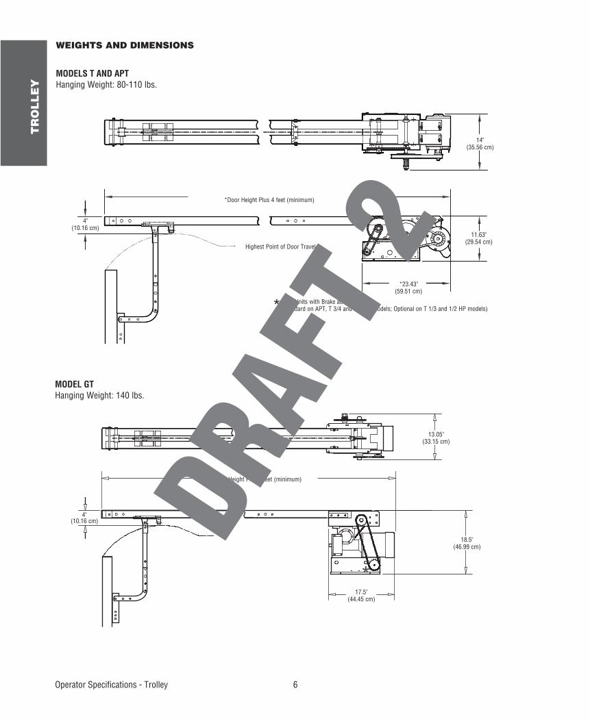
11.63"(29.54 cm)
*Door Height Plus 4 feet (minimum)
*23.43"(59.51 cm)
14"(35.56 cm)
Highest Point of Door Travel
4"(10.16 cm)
*- For Units with Brake add 3-1/2"(Standard on APT, T 3/4 and T 1 HP models; Optional on T 1/3 and 1/2 HP models)
WEIGHTS AND DIMENSIONS
MODELS T AND APTHanging Weight: 80-110 lbs.
*
MODEL GTHanging Weight: 140 lbs.
Door Height Plus 4 feet (minimum)
13.05"(33.15 cm)
18.5"(46.99 cm)
17.5"(44.45 cm)
4"(10.16 cm)
7
TR
OL
LE
Y
Assembly - Trolley
1
2
4
5
3
6
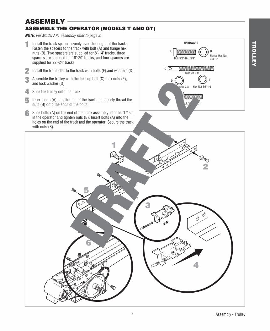
ASSEMBLE THE OPERATOR (MODELS T AND GT) ASSEMBLY
NOTE: For Model APT assembly refer to page 9.
1 Install the track spacers evenly over the length of the track. Fasten the spacers to the track with bolt (A) and fl ange hex nuts (B). Two spacers are supplied for 8’-14’ tracks, three spacers are supplied for 16’-20’ tracks, and four spacers are supplied for 22’-24’ tracks.
2 Install the front idler to the track with bolts (F) and washers (D).
3 Assemble the trolley with the take up bolt (C), hex nuts (E), and lock washer (D).
4 Slide the trolley onto the track.
5 Insert bolts (A) into the end of the track and loosely thread the nuts (B) onto the ends of the bolts.
6 Slide bolts (A) on the end of the track assembly into the “L” slot in the operator and tighten nuts (B). Insert bolts (A) into the holes on the end of the track and the operator. Secure the track with nuts (B).
HARDWARE
Bolt 3/8"-16 x 3/4"
Bolt 3/8"-16 x 1"
Take Up Bolt
Lock Washer 3/8" Hex Nut 3/8"-16
Flange Hex Nut 3/8"-16
A B
C
D E
F
TR
OL
LE
Y
8 Assembly - Trolley
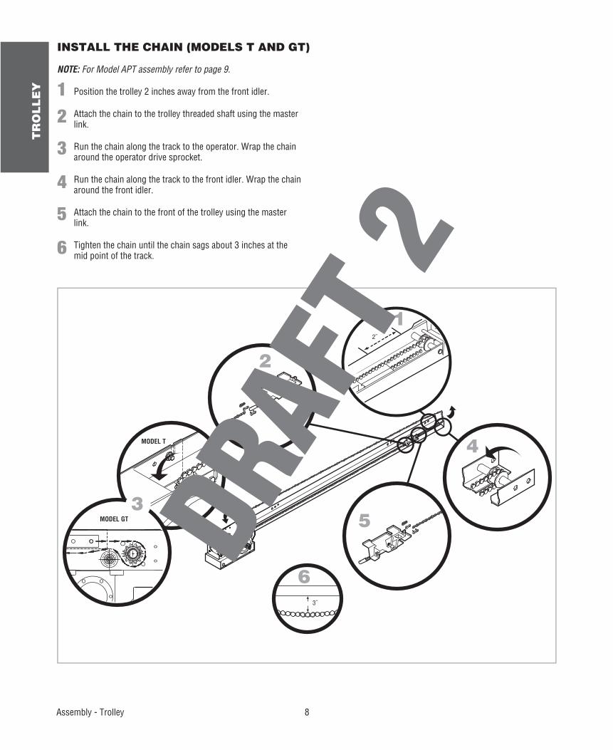
INSTALL THE CHAIN (MODELS T AND GT)
3˝
2˝
1
2
4
5
6
3
NOTE: For Model APT assembly refer to page 9.
1 Position the trolley 2 inches away from the front idler.
2 Attach the chain to the trolley threaded shaft using the master link.
3 Run the chain along the track to the operator. Wrap the chain around the operator drive sprocket.
4 Run the chain along the track to the front idler. Wrap the chain around the front idler.
5 Attach the chain to the front of the trolley using the master link.
6 Tighten the chain until the chain sags about 3 inches at the mid point of the track.
MODEL T
MODEL GT
9
TR
OL
LE
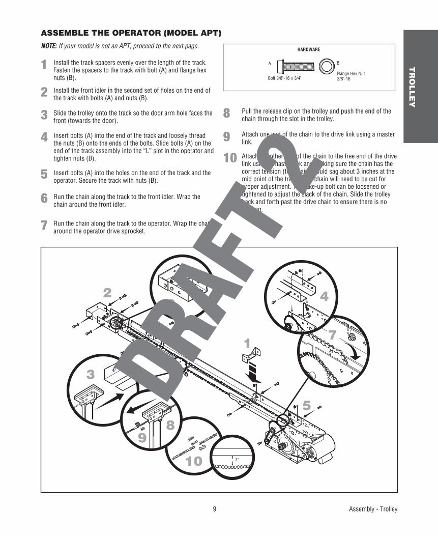
YASSEMBLE THE OPERATOR (MODEL APT)
NOTE: If your model is not an APT, proceed to the next page.HARDWARE
Bolt 3/8"-16 x 3/4"Flange Hex Nut 3/8"-16
A B
Assembly - Trolley
1
26
3
3˝10
4
7
89
5
Pull the release clip on the trolley and push the end of the chain through the slot in the trolley.
Install the track spacers evenly over the length of the track. Fasten the spacers to the track with bolt (A) and fl ange hex nuts (B).
Install the front idler in the second set of holes on the end of the track with bolts (A) and nuts (B).
Slide the trolley onto the track so the door arm hole faces the front (towards the door).
Insert bolts (A) into the end of the track and loosely thread the nuts (B) onto the ends of the bolts. Slide bolts (A) on the end of the track assembly into the “L” slot in the operator and tighten nuts (B).
Insert bolts (A) into the holes on the end of the track and the operator. Secure the track with nuts (B).
Run the chain along the track to the front idler. Wrap the chain around the front idler.
Run the chain along the track to the operator. Wrap the chain around the operator drive sprocket.
Attach one end of the chain to the drive link using a master link.
Attach the other end of the chain to the free end of the drive link using a master link and making sure the chain has the correct tension (the chain should sag about 3 inches at the mid point of the track). The chain will need to be cut for proper adjustment. The take-up bolt can be loosened or tightened to adjust the slack of the chain. Slide the trolley back and forth past the drive chain to ensure there is no binding.
1
2
3
4
5
6
7
8
9
10
TR
OL
LE
Y
10 Typical Installation - Trolley
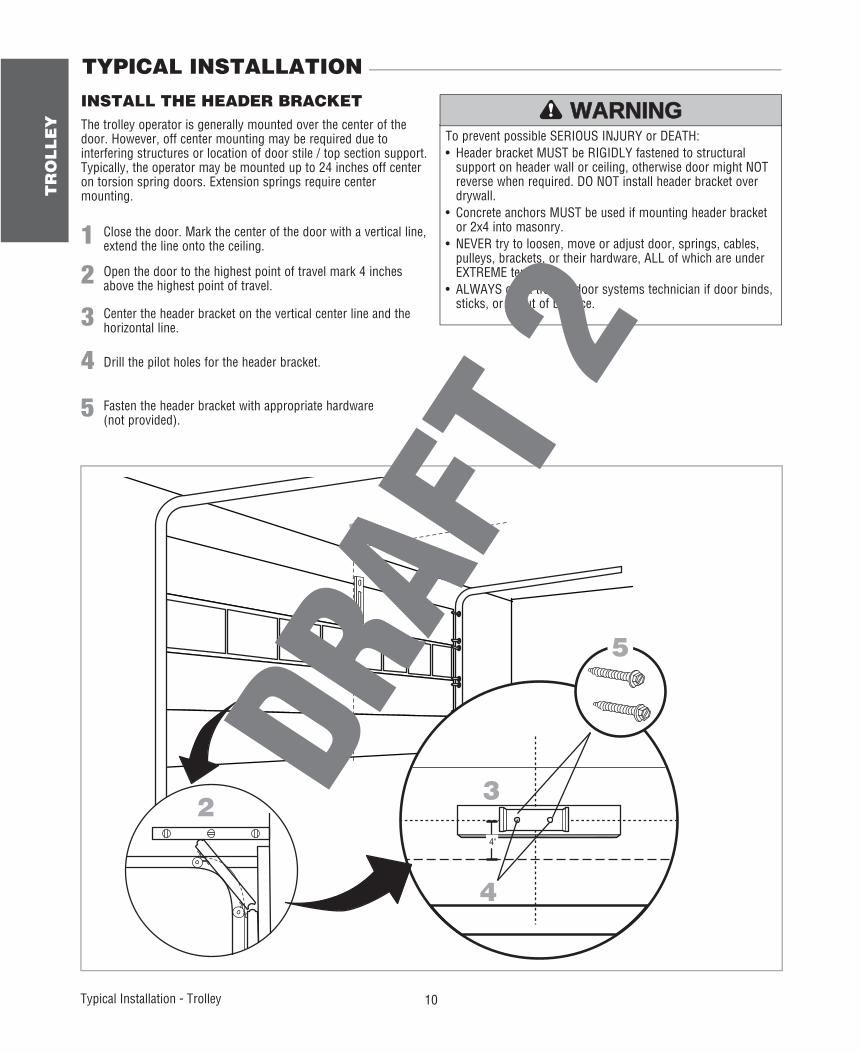
TYPICAL INSTALLATION
To prevent possible SERIOUS INJURY or DEATH:• Header bracket MUST be RIGIDLY fastened to structural
support on header wall or ceiling, otherwise door might NOT reverse when required. DO NOT install header bracket over drywall.
• Concrete anchors MUST be used if mounting header bracket or 2x4 into masonry.
• NEVER try to loosen, move or adjust door, springs, cables, pulleys, brackets, or their hardware, ALL of which are under EXTREME tension.
• ALWAYS call a trained door systems technician if door binds, sticks, or is out of balance.
ATTENTION
AVERTISSEMENT AVERTISSEMENT
AVERTISSEMENT
WARNING WARNING
CAUTION
WARNING
WARNING
PRECAUCIÓN ADVERTENCIA
ADVERTENCIA ADVERTENCIA
1 Close the door. Mark the center of the door with a vertical line, extend the line onto the ceiling.
INSTALL THE HEADER BRACKET
2 Open the door to the highest point of travel mark 4 inches above the highest point of travel.
1
2
4
3
4"
5
The trolley operator is generally mounted over the center of the door. However, off center mounting may be required due to interfering structures or location of door stile / top section support. Typically, the operator may be mounted up to 24 inches off center on torsion spring doors. Extension springs require center mounting.
3
4
Center the header bracket on the vertical center line and the horizontal line.
Drill the pilot holes for the header bracket.
5 Fasten the header bracket with appropriate hardware (not provided).
11
TR
OL
LE
Y
Typical Installation - Trolley
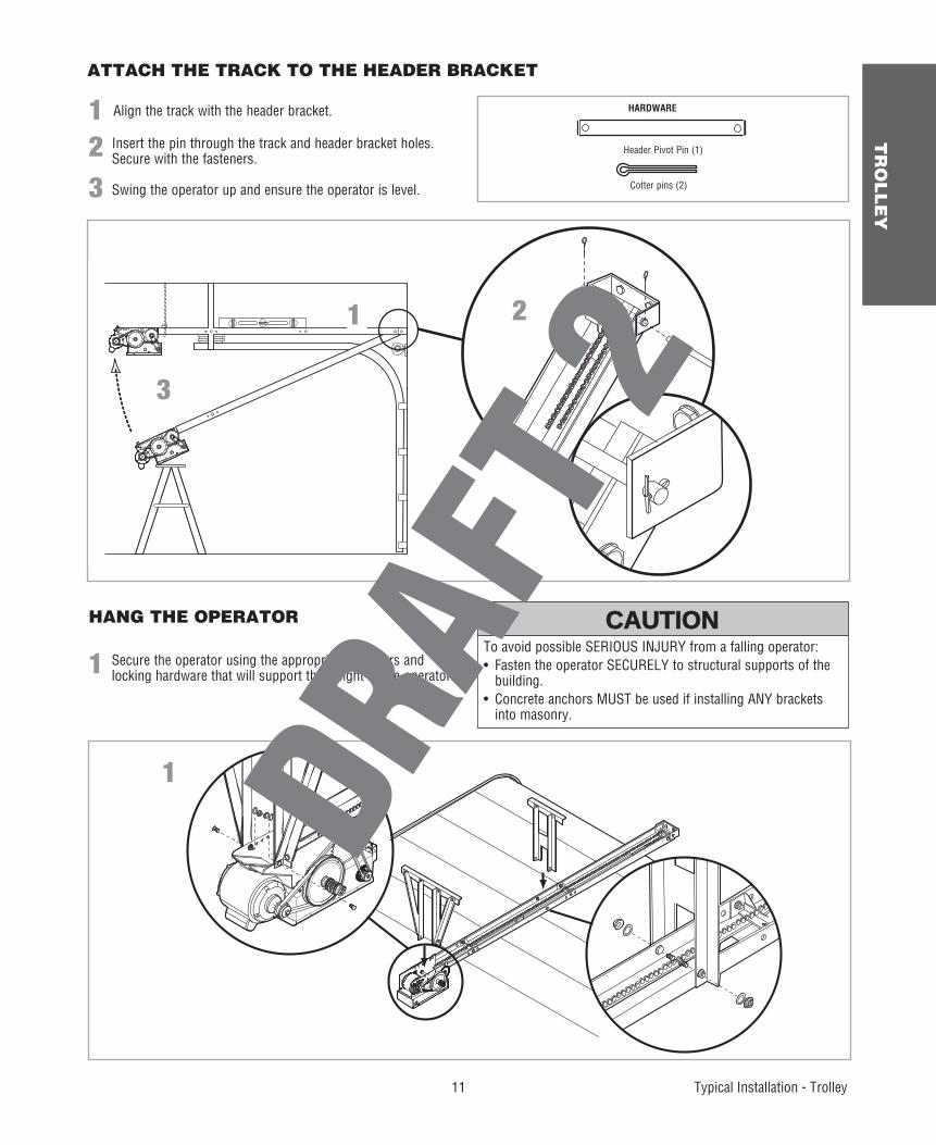
ATTACH THE TRACK TO THE HEADER BRACKET
HANG THE OPERATOR
1 Secure the operator using the appropriate fasteners and locking hardware that will support the weight of the operator.
1
1
3
2
To avoid possible SERIOUS INJURY from a falling operator:• Fasten the operator SECURELY to structural supports of the
building.• Concrete anchors MUST be used if installing ANY brackets
into masonry.
ATTENTION
AVERTISSEMENT AVERTISSEMENT
AVERTISSEMENT
WARNING
CAUTION CAUTION
WARNING
WARNING
PRECAUCIÓN ADVERTENCIA
ADVERTENCIA ADVERTENCIA
1 Align the track with the header bracket.
23
Insert the pin through the track and header bracket holes. Secure with the fasteners.
Swing the operator up and ensure the operator is level.
HARDWARE
Header Pivot Pin (1)
Cotter pins (2)
TR
OL
LE
Y
12 Typical Installation - Trolley
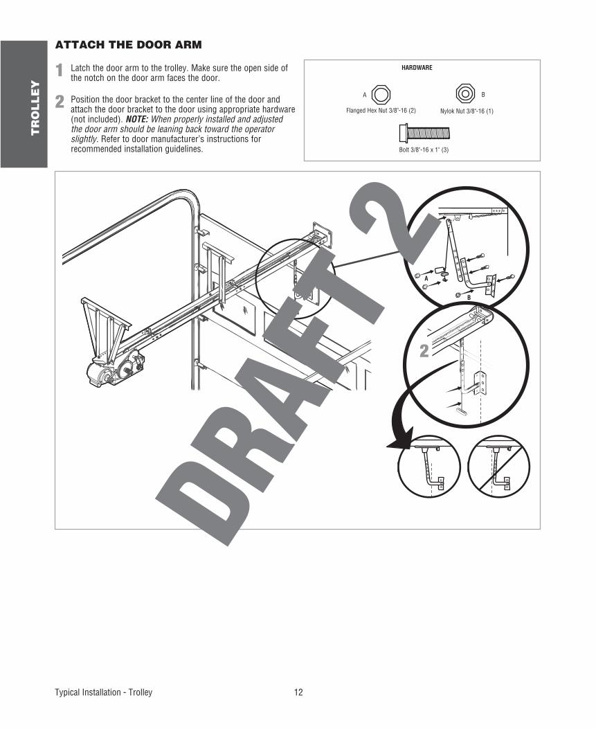
ATTACH THE DOOR ARM
1
2
Latch the door arm to the trolley. Make sure the open side of the notch on the door arm faces the door.
Position the door bracket to the center line of the door and attach the door bracket to the door using appropriate hardware (not included). NOTE: When properly installed and adjusted the door arm should be leaning back toward the operator slightly. Refer to door manufacturer’s instructions for recommended installation guidelines.
NO ECIT
1
2
HARDWARE
A
B
Nylok Nut 3/8"-16 (1)Flanged Hex Nut 3/8"-16 (2)
A B
Bolt 3/8"-16 x 1" (3)
13
HO
IST
AN
D J
AC
KS
HA
FT
Carton Inventory/Operator Specifi cations - Hoist and Jackshaft
OPERATOR SPECIFICATIONS
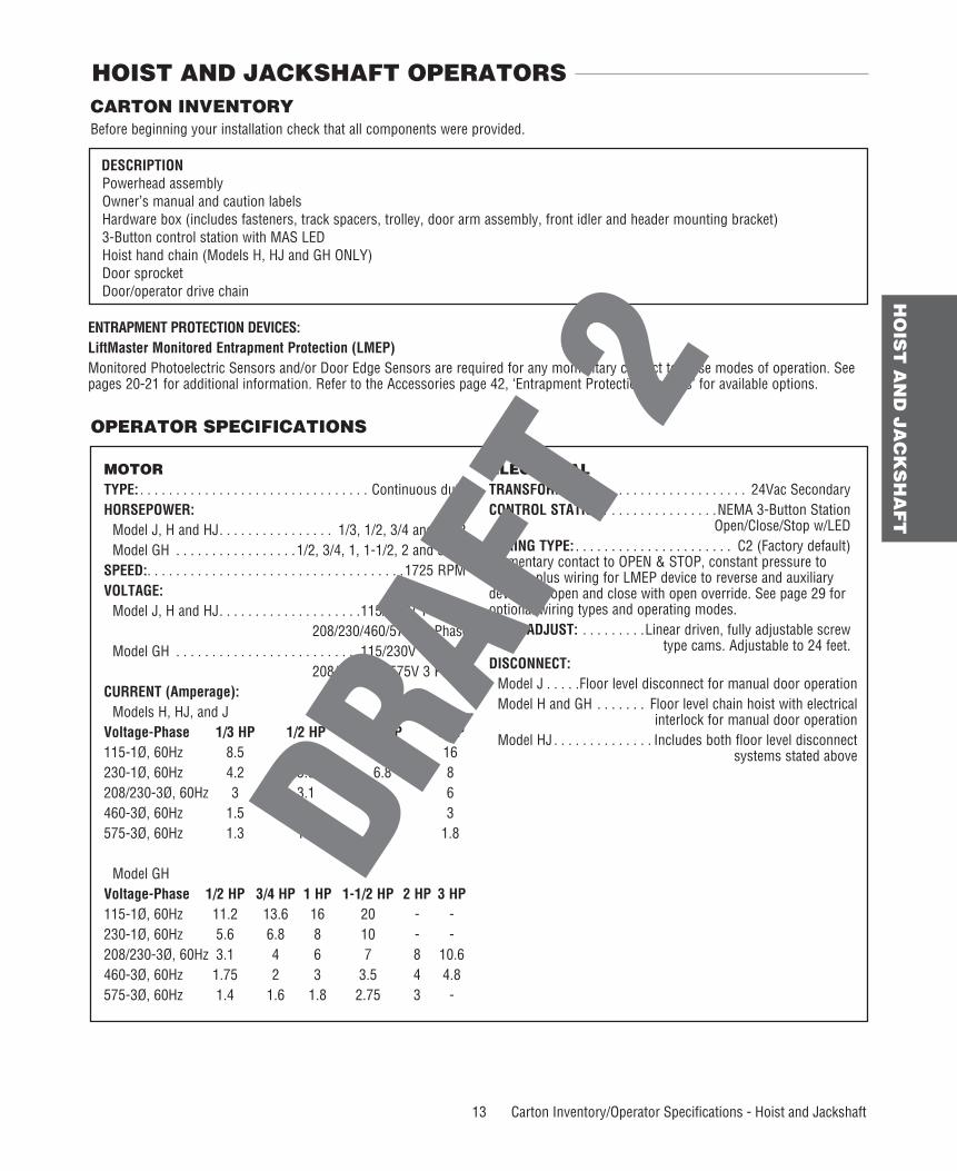
CARTON INVENTORYBefore beginning your installation check that all components were provided.
DESCRIPTION Powerhead assembly Owner’s manual and caution labels Hardware box (includes fasteners, track spacers, trolley, door arm assembly, front idler and header mounting bracket) 3-Button control station with MAS LED Hoist hand chain (Models H, HJ and GH ONLY) Door sprocket Door/operator drive chain
HOIST AND JACKSHAFT OPERATORS
MOTORTYPE: . . . . . . . . . . . . . . . . . . . . . . . . . . . . . . . . Continuous dutyHORSEPOWER: Model J, H and HJ . . . . . . . . . . . . . . . . 1/3, 1/2, 3/4 and 1 HP Model GH . . . . . . . . . . . . . . . . .1/2, 3/4, 1, 1-1/2, 2 and 3 HPSPEED:. . . . . . . . . . . . . . . . . . . . . . . . . . . . . . . . . . . .1725 RPMVOLTAGE: Model J, H and HJ . . . . . . . . . . . . . . . . . . . .115/230V 1 Phase
208/230/460/575V 3 Phase Model GH . . . . . . . . . . . . . . . . . . . . . . . . . .115/230V 1 Phase
208/230/460/575V 3 PhaseCURRENT (Amperage): Models H, HJ, and JVoltage-Phase 1/3 HP 1/2 HP 3/4 HP 1 HP115-1Ø, 60Hz 8.5 11.2 13.6 16230-1Ø, 60Hz 4.2 5.6 6.8 8208/230-3Ø, 60Hz 3 3.1 4 6460-3Ø, 60Hz 1.5 1.75 2 3575-3Ø, 60Hz 1.3 1.4 1.6 1.8
Model GHVoltage-Phase 1/2 HP 3/4 HP 1 HP 1-1/2 HP 2 HP 3 HP115-1Ø, 60Hz 11.2 13.6 16 20 - -230-1Ø, 60Hz 5.6 6.8 8 10 - -208/230-3Ø, 60Hz 3.1 4 6 7 8 10.6460-3Ø, 60Hz 1.75 2 3 3.5 4 4.8575-3Ø, 60Hz 1.4 1.6 1.8 2.75 3 -
ELECTRICALTRANSFORMER: . . . . . . . . . . . . . . . . . . . . . . 24Vac SecondaryCONTROL STATION: . . . . . . . . . . . . . . .NEMA 3-Button Station Open/Close/Stop w/LEDWIRING TYPE: . . . . . . . . . . . . . . . . . . . . . . C2 (Factory default)Momentary contact to OPEN & STOP, constant pressure to CLOSE, plus wiring for LMEP device to reverse and auxiliary devices to open and close with open override. See page 29 for optional wiring types and operating modes.LIMIT ADJUST: . . . . . . . . .Linear driven, fully adjustable screw type cams. Adjustable to 24 feet.DISCONNECT: Model J . . . . .Floor level disconnect for manual door operation Model H and GH . . . . . . . Floor level chain hoist with electrical
interlock for manual door operation Model HJ . . . . . . . . . . . . . . Includes both floor level disconnect
systems stated above
ENTRAPMENT PROTECTION DEVICES:LiftMaster Monitored Entrapment Protection (LMEP)Monitored Photoelectric Sensors and/or Door Edge Sensors are required for any momentary contact to close modes of operation. See pages 20-21 for additional information. Refer to the Accessories page 42, ‘Entrapment Protection Devices’ for available options.
14
HO
IST
AN
D J
AC
KS
HA
FT
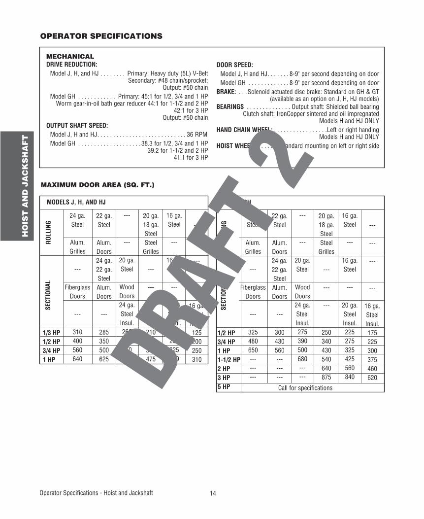
MAXIMUM DOOR AREA (SQ. FT.)
MODELS J, H, AND HJ
SECT
IONA
L
22 ga.Steel
Alum.Doors24 ga.22 ga.SteelAlum.Doors
---
285350500625
24 ga.Steel
Alum.Grilles
---
FiberglassDoors
---
310400560640
---
---
20 ga.Steel
WoodDoors24 ga.SteelInsul.260320450560
20 ga.18 ga.SteelSteel
Grilles
---
---
---
210280380475
---
---
---
---
16 ga.SteelInsul.125200250310
1/3 HP1/2 HP3/4 HP1 HP
ROLL
ING
16 ga.Steel
---
16 ga.Steel
---
20 ga.SteelInsul.175250325400
MODEL GH
SECT
IONA
L22 ga.Steel
Alum.Doors24 ga.22 ga.SteelAlum.Doors
---
300430560---------
24 ga.Steel
Alum.Grilles
---
FiberglassDoors
---
325480650---------
---
---
20 ga.Steel
WoodDoors24 ga.SteelInsul.275390500680------
20 ga.18 ga.SteelSteel
Grilles
---
---
---
250340430540640875
---
---
---
---
16 ga.SteelInsul.175225300375460620
1/2 HP3/4 HP1 HP1-1/2 HP2 HP3 HP5 HP
ROLL
ING
16 ga.Steel
---
16 ga.Steel
---
20 ga.SteelInsul.225275325425560840
Call for specifications
Operator Specifi cations - Hoist and Jackshaft
MECHANICALDRIVE REDUCTION: Model J, H, and HJ . . . . . . . . Primary: Heavy duty (5L) V-Belt
Secondary: #48 chain/sprocket;Output: #50 chain
Model GH . . . . . . . . . . . . Primary: 45:1 for 1/2, 3/4 and 1 HPWorm gear-in-oil bath gear reducer 44:1 for 1-1/2 and 2 HP
42:1 for 3 HPOutput: #50 chain
OUTPUT SHAFT SPEED: Model J, H and HJ . . . . . . . . . . . . . . . . . . . . . . . . . . . . 36 RPM Model GH . . . . . . . . . . . . . . . . . . . . 38.3 for 1/2, 3/4 and 1 HP
39.2 for 1-1/2 and 2 HP41.1 for 3 HP
DOOR SPEED: Model J, H and HJ . . . . . . . 8-9" per second depending on door Model GH . . . . . . . . . . . . . 8-9" per second depending on doorBRAKE: . . .Solenoid actuated disc brake: Standard on GH & GT
(available as an option on J, H, HJ models)BEARINGS . . . . . . . . . . . . . . Output shaft: Shielded ball bearing
Clutch shaft: IronCopper sintered and oil impregnatedModels H and HJ ONLY
HAND CHAIN WHEEL: . . . . . . . . . . . . . . . . .Left or right handingModels H and HJ ONLY
HOIST WHEEL: . . . . . . . Standard mounting on left or right side
OPERATOR SPECIFICATIONS
15
HO
IST
AN
D J
AC
KS
HA
FT
A
A A
B B
BB
A
13.75"(34.93 cm)
1.5" (3.81 cm)
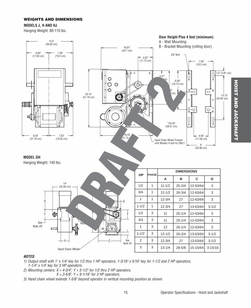
Door Height Plus 4 feet (minimum)A - Wall MountingB - Bracket Mounting (rolling door)
6.59"(16.74 cm)
5.5"(14 cm)
10.5"(26.67 cm)
Hand Chain Wheel Presentwith Models H and HJ ONLY
WEIGHTS AND DIMENSIONS
MODELS J, H AND HJHanging Weight: 80-110 lbs.
14 "
WEIGHTS AND DIMENSIONS HANGING WEIGHT : .........80-1 10 LBS.
Hand Chain Wheel
SeeNote #1See
Note #2
A
X
BY
C
D
Y
SeeNote #3
A
11-1/2
12-1/2
12-3/4
12-3/4
11
11
12
12-1/2
12-3/4
13-1/4
B
25-3/4
26-3/4
27
27
25-1/4
25-1/4
26-1/4
26-3/4
27
28-5/8
C
12-63/64
12-63/64
12-63/64
13-63/64
12-63/64
12-63/64
12-63/64
13-63/64
13-63/64
15-15/64
D
3
3
3
3-1/2
3
3
3
3-1/2
3-1/2
3-15/16
1/2
3/4
1
1-1/2
1/2
3/4
1
1-1/2
2
3
1
1
1
1
3
3
3
3
3
3
HP DIMENSIONS
PHASE
MODEL GHHanging Weight: 140 lbs.
Operator Specifi cations - Hoist and Jackshaft
14.5"(36.83 cm)
16.81"(42.7 cm)
6.94"(17.63 cm)
7.56"(19.2 cm)
7.56"(19.2 cm)
4.62"(11.73 cm)
3/8" Bolt
4.41"(11.2 cm)
4.56"(11.58 cm)
9"(22.86 cm)
7.62"(19.35 cm)
20.15"(51.18 cm)
16.43"(41.73 cm)
14"(35.56 cm)
8.34" (21.18 cm)
NOTES:1) Output shaft with 1" x 1/4" key for 1/2 thru 1 HP operators, 1-3/16" x 5/16" key for 1-1/2 and 2 HP operators, 1-1/4" x 1/4" key for 3 HP operators.2) Mounting centers: X = 4-3/4"; Y = 5-1/2" for 1/2 thru 2 HP operators.
X = 3-5/8"; Y = 9-1/16" for 3 HP operators.3) Hand chain wheel extends 1-5/8" beyond operator in vertical mounting position as shown.
*23.43"(59.51 cm)
16
HO
IST
AN
D J
AC
KS
HA
FT
Assembly/Typical Installation - Hoist and Jackshaft
DETERMINE MOUNTING LOCATION
TYPICAL INSTALLATION
1
1
1a1b
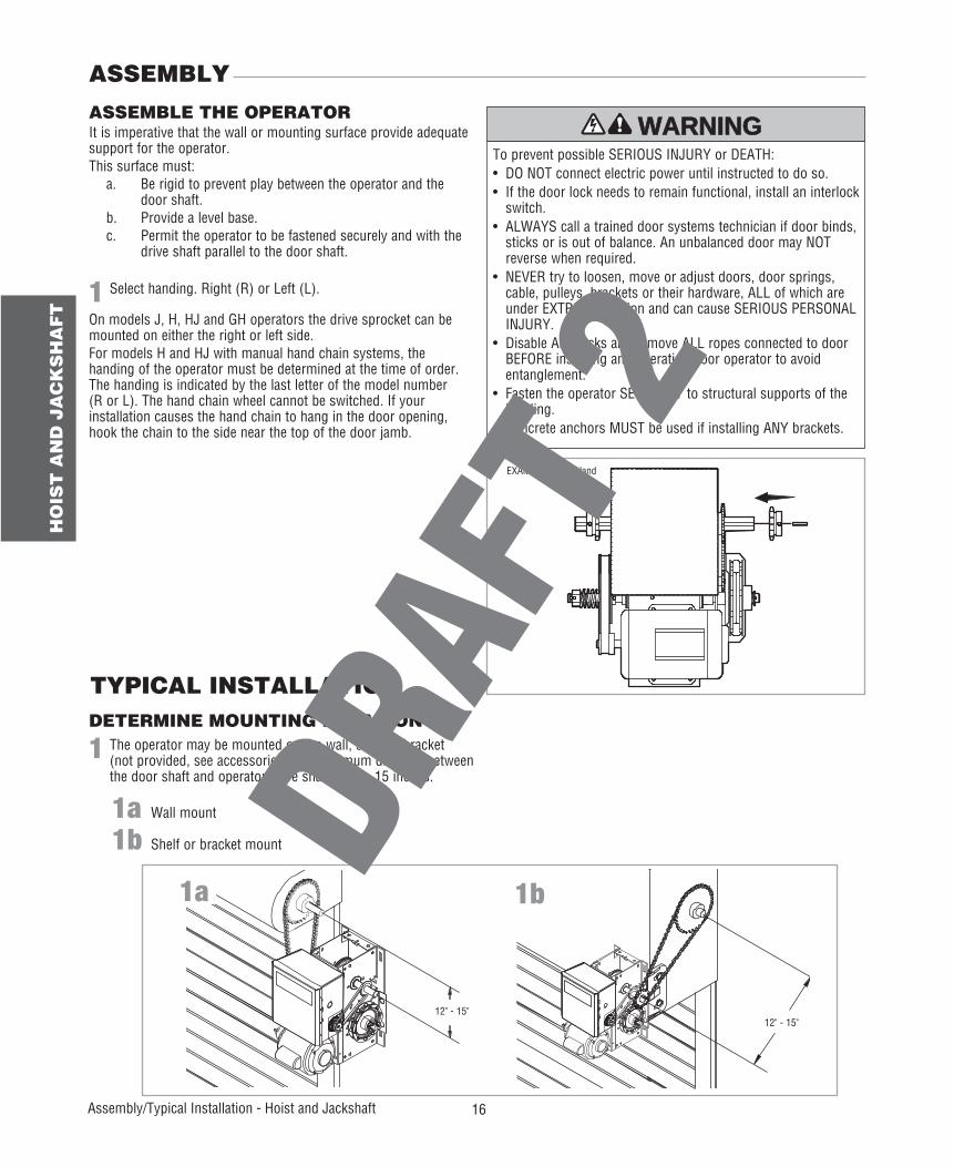
Select handing. Right (R) or Left (L).
On models J, H, HJ and GH operators the drive sprocket can be mounted on either the right or left side.For models H and HJ with manual hand chain systems, the handing of the operator must be determined at the time of order. The handing is indicated by the last letter of the model number (R or L). The hand chain wheel cannot be switched. If your installation causes the hand chain to hang in the door opening, hook the chain to the side near the top of the door jamb.
The operator may be mounted on the wall, shelf or bracket (not provided, see accessories). The optimum distance between the door shaft and operator drive shaft is 12 - 15 inches.
Wall mount
Shelf or bracket mount
It is imperative that the wall or mounting surface provide adequate support for the operator.This surface must: a. Be rigid to prevent play between the operator and the
door shaft. b. Provide a level base. c. Permit the operator to be fastened securely and with the
drive shaft parallel to the door shaft.
To prevent possible SERIOUS INJURY or DEATH:• DO NOT connect electric power until instructed to do so.• If the door lock needs to remain functional, install an interlock
switch.• ALWAYS call a trained door systems technician if door binds,
sticks or is out of balance. An unbalanced door may NOT reverse when required.
• NEVER try to loosen, move or adjust doors, door springs, cable, pulleys, brackets or their hardware, ALL of which are under EXTREME tension and can cause SERIOUS PERSONAL INJURY.
• Disable ALL locks and remove ALL ropes connected to door BEFORE installing and operating door operator to avoid entanglement.
• Fasten the operator SECURELY to structural supports of the building.
• Concrete anchors MUST be used if installing ANY brackets.ATTENTION
AVERTISSEMENT AVERTISSEMENT
AVERTISSEMENT
WARNING
CAUTION
WARNING
WARNING WARNING
PRECAUCIÓN ADVERTENCIA
ADVERTENCIA ADVERTENCIA
ASSEMBLE THE OPERATOR
ASSEMBLY
1a 1b
12" - 15"12" - 15"
EXAMPLE: Right Hand
17
HO
IST
AN
D J
AC
KS
HA
FT
Typical Installation - Hoist and Jackshaft
MOUNTING
INSTALL THE MANUAL DISCONNECT
1
1
2
3
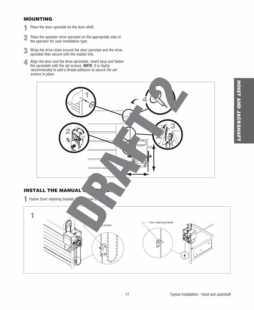
Place the door sprocket on the door shaft.
Fasten Door retaining bracket 4 feet above the floor.
Place the operator drive sprocket on the appropriate side of the operator for your installation type.
Wrap the drive chain around the door sprocket and the drive sprocket then secure with the master link.
4 Align the door and the drive sprockets. Insert keys and fasten the sprockets with the set screws. NOTE: It is highly recommended to add a thread adhesive to secure the set screws in place.
1
23
4
1Door retaining bracket
Door retaining bracket
18
WIR
ING
Wiring
WIRING
To reduce the risk of SEVERE INJURY or DEATH:• ANY maintenance to the operator or in the area near the
operator MUST NOT be performed until disconnecting the electrical power and locking-out the power. Upon completion of maintenance the area MUST be cleared and secured, at that time the unit may be returned to service.
• Disconnect power at the fuse box BEFORE proceeding. Operator MUST be properly grounded and connected in accordance with national and local electrical codes. The operator should be on a separate fused line of adequate capacity.
• ALL electrical connections MUST be made by a qualified individual.
• DO NOT install ANY wiring or attempt to run the operator without consulting the wiring diagram.
• ALL power wiring should be on a dedicated circuit and well protected. The location of the power disconnect should be visible and clearly labeled.
• ALL power and control wiring MUST be run in separate conduit.
Three Phase Power WiringSingle Phase Power Wiring
Line Power115/230 VacSingle Phase
Hot
Neutral
Ground
Phase 1
Phase 2
Phase 3
WARNING
WARNING
WARNING WARNING
2
1 3
Line Power208/230/460/575 VacThree Phase
POWER AND GROUND
MOTOR POWER PLUG SELECTION
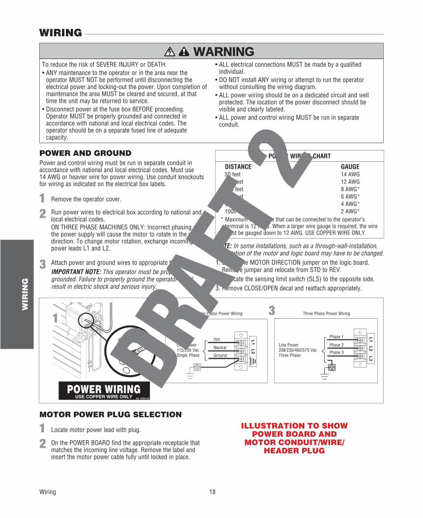
Power and control wiring must be run in separate conduit in accordance with national and local electrical codes. Must use 14 AWG or heavier wire for power wiring. Use conduit knockouts for wiring as indicated on the electrical box labels.
Remove the operator cover.
Locate motor power lead with plug.
Attach power and ground wires to appropriate terminals.IMPORTANT NOTE: This operator must be properly grounded. Failure to properly ground the operator could result in electric shock and serious injury.
NOTE: In some installations, such as a through-wall-installation, the rotation of the motor and logic board may have to be changed.1. Locate the MOTOR DIRECTION jumper on the logic board.
Remove jumper and relocate from STD to REV.2. Relocate the sensing limit switch (SLS) to the opposite side.3. Remove CLOSE/OPEN decal and reattach appropriately.
1
1
3
2
2
Run power wires to electrical box according to national and local electrical codes.ON THREE PHASE MACHINES ONLY: Incorrect phasing of the power supply will cause the motor to rotate in the wrong direction. To change motor rotation, exchange incoming power leads L1 and L2.
On the POWER BOARD find the appropriate receptacle that matches the incoming line voltage. Remove the label and insert the motor power cable fully until locked in place.
DISTANCE GAUGE 50 feet 14 AWG 100 feet 12 AWG 200 feet 8 AWG* 350 feet 6 AWG* 500 feet 4 AWG* 1000 feet 2 AWG*
POWER WIRING CHART
* Maximum wire gauge that can be connected to the operator’s terminal is 12 AWG. When a larger wire gauge is required, the wire must be gauged down to 12 AWG. USE COPPER WIRE ONLY.
ILLUSTRATION TO SHOW POWER BOARD AND
MOTOR CONDUIT/WIRE/HEADER PLUG
19
WIR
ING
Wiring
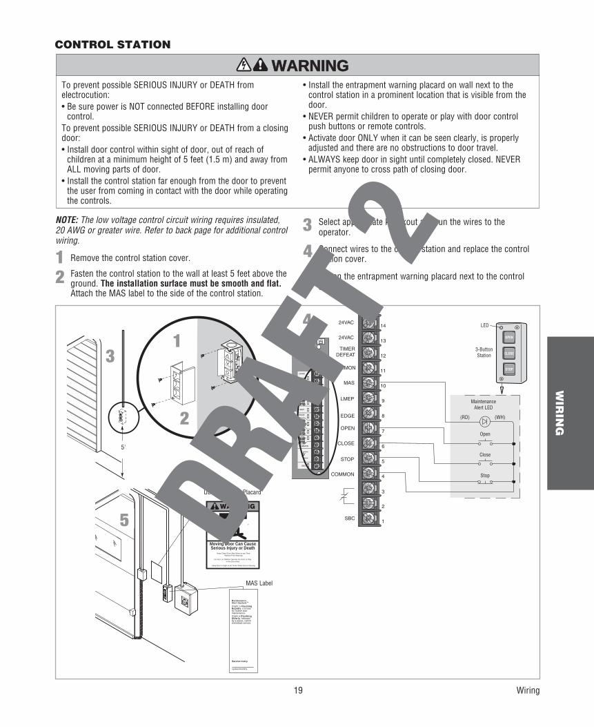
Remove the control station cover.
Select appropriate knockout and run the wires to the operator.
1Connect wires to the control station and replace the control station cover.4
3
Fasten the entrapment warning placard next to the control station.52 Fasten the control station to the wall at least 5 feet above the
ground. The installation surface must be smooth and flat. Attach the MAS label to the side of the control station.
DATA
24VAC
24VAC
LMEP:
EDGE:
OPEN
CLOSE
STOP
COMMON
SBC
MAS
COMMON
TIMERDEFEAT
POWER
MERABLE
3-PH
AS
E
Open
Close
Stop
MaintenanceAlert LED
(WH)(RD)
3-ButtonStation
OPEN
CLOSE
STOP
24VAC
24VAC
TIMERDEFEAT
COMMON
MAS
LMEP
EDGE
OPEN
CLOSE
STOP
COMMON
SBC
11
10
9
14
13
12
8
7
6
5
4
3
2
1
LED
CONTROL STATION
4
^
O
OPEN
STOP
^CLOSE
5'
1
2
3
To prevent possible SERIOUS INJURY or DEATH from electrocution:• Be sure power is NOT connected BEFORE installing door
control.To prevent possible SERIOUS INJURY or DEATH from a closing door:• Install door control within sight of door, out of reach of
children at a minimum height of 5 feet (1.5 m) and away from ALL moving parts of door.
• Install the control station far enough from the door to prevent the user from coming in contact with the door while operating the controls.
• Install the entrapment warning placard on wall next to the control station in a prominent location that is visible from the door.
• NEVER permit children to operate or play with door control push buttons or remote controls.
• Activate door ONLY when it can be seen clearly, is properly adjusted and there are no obstructions to door travel.
• ALWAYS keep door in sight until completely closed. NEVER permit anyone to cross path of closing door.
ATTENTION
AVERTISSEMENT AVERTISSEMENT
AVERTISSEMENT
WARNING
CAUTION
WARNING
WARNING WARNING
PRECAUCIÓN ADVERTENCIA
ADVERTENCIA ADVERTENCIA
WARNING
Keep Door in Sight at all Times When Door is Moving
Moving Door Can CauseSerious Injury or Death
Keep Clear! Door May Move at any TimeWithout Prior Warning
Do Not Let Children Operate the Door or Playin the Door Area
MaintenanceAlert SystemTM
If light is FlashingRapidly, it is timefor routine doormaintenance.If light is FlashingSlowly, followedby a pause, call forimmediate service.
Service every
cycles/months
5
NOTE: The low voltage control circuit wiring requires insulated, 20 AWG or greater wire. Refer to back page for additional control wiring.
UL Entrapment Placard
MAS Label

20
EN
TR
AP
ME
NT
PR
OT
EC
TIO
N
Entrapment Protection
To prevent possible SERIOUS INJURY or DEATH from a closing door:• Be sure power is NOT connected to the door operator BEFORE
installing the photoelectric sensor.• The door MUST be in the fully opened or closed position
BEFORE installing the LiftMaster Monitored Entrapment Protection device.
To prevent SERIOUS INJURY, DEATH, ENTRAPMENT, or PROPERTY DAMAGE:• Correctly connect and align the photoelectric sensor.• Install the photoelectric sensor beam NO HIGHER than
6" (15 cm) above the floor.• This is a required LMEP device for B2, TS, T, and FSTS wiring
types and MUST NOT be disabled. For D1, C2, and E2 wiring the installation of an entrapment protection device is recommended.
• LiftMaster Monitored Entrapment Protection devices are for use with LiftMaster Commercial Door Operators ONLY. Use with ANY other product voids the warranty.
• If an edge sensor is being used on a horizontal slide door, then place one or more edge sensors on both the leading and trailing edge.
• If an edge sensor is being used on a vertically moving door, then place edge sensors on the bottom edge of the door.
ATTENTION
AVERTISSEMENT AVERTISSEMENT
AVERTISSEMENT
WARNING
CAUTION
WARNING
WARNING WARNING
PRECAUCIÓN ADVERTENCIA
ADVERTENCIA ADVERTENCIA
LIFTMASTER MONITORED ENTRAPMENT PROTECTION (LMEP)
Invisible Light BeamProtection Area
Monitored Photoelectric Sensor 6" (15 cm) max. above floor and from the door.
Monitored Edge Sensormounted to the bottom of door.
Monitored Photoelectric Sensor 6" (15 cm) max. above floor and from the door.
ENTRAPMENT PROTECTION
IMPORTANT INFORMATION ABOUT THE LIFTMASTER MONITORED ENTRAPMENT PROTECTION DEVICESA LiftMaster Monitored Entrapment Protection (LMEP) device is required for most wiring types (refer to page 28). If a LiftMaster Monitored Entrapment Protection device is not installed, constant pressure to close will be required from the control station.Refer to Accessories page for a complete list of LMEP devices.
TYPICAL ENTRAPMENT PROTECTION DEVICE(S) OVERVIEW
21
EN
TR
AP
ME
NT
PR
OT
EC
TIO
N
Entrapment Protection
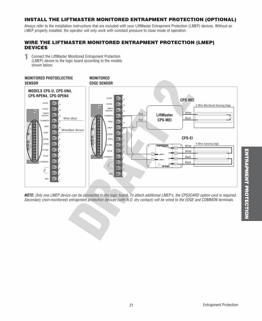
INSTALL THE LIFTMASTER MONITORED ENTRAPMENT PROTECTION (OPTIONAL)Always refer to the installation instructions that are included with your LiftMaster Entrapment Protection (LMEP) devices. Without an LMEP properly installed, the operator will only work with constant pressure to close mode of operation.
WIRE THE LIFTMASTER MONITORED ENTRAPMENT PROTECTION (LMEP) DEVICES
Connect the LiftMaster Monitored Entrapment Protection (LMEP) device to the logic board according to the models shown below:
1
DATA
24VAC
24VAC
LMEP:
EDGE:
OPEN
CLOSE
STOP
COMMON
SBC
MAS
COMMON
TIMERDEFEAT
POWER
24VAC
24VAC
TIMERDEFEAT
COMMON
MAS
LMEP
EDGE
OPEN
CLOSE
STOP
COMMON
SBC
11
10
9
14
13
12
8
7
6
5
4
3
2
1
White (Blue)
White/Black (Brown)
MODELS CPS-U, CPS-UN4, CPS-RPEN4, CPS-OPEN4
DATA
24VAC
24VAC
LMEP:
EDGE:
OPEN
CLOSE
STOP
COMMON
SBC
MAS
COMMON
TIMERDEFEAT
POWER
24VAC
24VAC
TIMERDEFEAT
COMMON
MAS
LMEP
EDGE
OPEN
CLOSE
STOP
COMMON
SBC
11
10
9
14
13
12
8
7
6
5
4
3
2
140-34141-1
LMEP2
LMEP1
E1
E2
E3
E4
CPS-EI
MONITORED PHOTOELECTRIC SENSOR
MONITORED EDGE SENSOR
White
White
White
Black
Black
Black
4-Wire Sensing Edge
2-Wire Monitored Sensing Edge
Red
Red
CPS-MEI
CPS-EI
NOTE: Only one LMEP device can be connected to the logic board. To attach additional LMEP’s, the CPS3CARD option card is required. Secondary (non-monitored) entrapment protection devices (with N.O. dry contact) will be wired to the EDGE and COMMON terminals.
LiftMasterCPS-MEI
22
AD
JU
ST
ME
NT
Adjustment
ADJUSTMENT
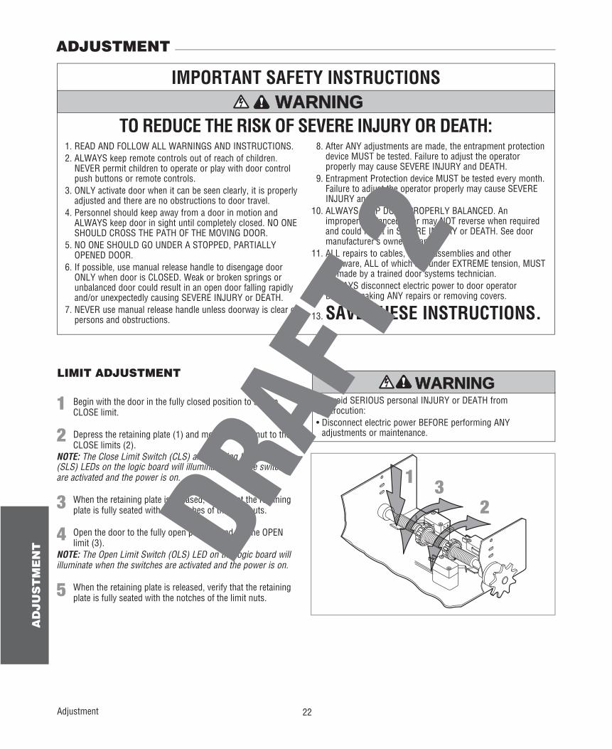
LIMIT ADJUSTMENT
To avoid SERIOUS personal INJURY or DEATH from electrocution:• Disconnect electric power BEFORE performing ANY
adjustments or maintenance.
ATTENTION
AVERTISSEMENT AVERTISSEMENT
AVERTISSEMENT
WARNING
CAUTION
WARNING
WARNING WARNING
PRECAUCIÓN ADVERTENCIA
ADVERTENCIA ADVERTENCIA
TO REDUCE THE RISK OF SEVERE INJURY OR DEATH:
IMPORTANT SAFETY INSTRUCTIONS
1. READ AND FOLLOW ALL WARNINGS AND INSTRUCTIONS.2. ALWAYS keep remote controls out of reach of children.
NEVER permit children to operate or play with door control push buttons or remote controls.
3. ONLY activate door when it can be seen clearly, it is properly adjusted and there are no obstructions to door travel.
4. Personnel should keep away from a door in motion and ALWAYS keep door in sight until completely closed. NO ONE SHOULD CROSS THE PATH OF THE MOVING DOOR.
5. NO ONE SHOULD GO UNDER A STOPPED, PARTIALLY OPENED DOOR.
6. If possible, use manual release handle to disengage door ONLY when door is CLOSED. Weak or broken springs or unbalanced door could result in an open door falling rapidly and/or unexpectedly causing SEVERE INJURY or DEATH.
7. NEVER use manual release handle unless doorway is clear of persons and obstructions.
8. After ANY adjustments are made, the entrapment protection device MUST be tested. Failure to adjust the operator properly may cause SEVERE INJURY and DEATH.
9. Entrapment Protection device MUST be tested every month. Failure to adjust the operator properly may cause SEVERE INJURY and DEATH.
10. ALWAYS KEEP DOOR PROPERLY BALANCED. An improperly balanced door may NOT reverse when required and could result in SEVERE INJURY or DEATH. See door manufacturer’s owners manual.
11. ALL repairs to cables, spring assemblies and other hardware, ALL of which are under EXTREME tension, MUST be made by a trained door systems technician.
12. ALWAYS disconnect electric power to door operator BEFORE making ANY repairs or removing covers.
13. SAVE THESE INSTRUCTIONS.
WARNING
WARNING
WARNING WARNING
1
23
1 Begin with the door in the fully closed position to set the CLOSE limit.
2 Depress the retaining plate (1) and move the limit nut to the CLOSE limits (2).
NOTE: The Close Limit Switch (CLS) and Sensing Limit Switch (SLS) LEDs on the logic board will illuminate when the switches are activated and the power is on.
3 When the retaining plate is released, verify that the retaining plate is fully seated with the notches of the limit nuts.
4 Open the door to the fully open position and set the OPEN limit (3).
NOTE: The Open Limit Switch (OLS) LED on the logic board will illuminate when the switches are activated and the power is on.
5 When the retaining plate is released, verify that the retaining plate is fully seated with the notches of the limit nuts.