Embed Size (px)
Citation preview

Industrial Design Application Industrial Design Application for Power Distribution for Power Distribution
over Extra-Long Distancesover Extra-Long Distances
OrOr
Lots of Wire Lots of Wire Little Vd Little Vd
Robert A Durham, PERobert A Durham, PE
New Dominion, LLCNew Dominion, LLC
Tulsa, OKTulsa, OK
Marcus O Durham, PhD, PEMarcus O Durham, PhD, PE
THEWAY CorpTHEWAY Corp
Tulsa, OKTulsa, OK

IntroductionIntroductionTypical petrochemical installations:Typical petrochemical installations:
Geographically confined Geographically confined Large loadsLarge loads
Utility installations:Utility installations: Geographically dispersedGeographically dispersed Distributed loadsDistributed loads
Large loads over large distance Large loads over large distance cause unique problemscause unique problems

• Downtime eliminatedDowntime eliminated• Protection system isolates faultsProtection system isolates faults• Total system voltage > 95%Total system voltage > 95%• Contingency is bi-directional feedContingency is bi-directional feed• Adequate Ampacity to prevent sagsAdequate Ampacity to prevent sags
IntroductionIntroductionGoalsGoals

LoadsLoads• Primary loads Primary loads
– 150 – 400 Hp, 2400 VAC150 – 400 Hp, 2400 VAC– 2 pole, low inertia2 pole, low inertia– Steep speed-torque curveSteep speed-torque curve– Centrifugal pumpsCentrifugal pumps– Eff Eff 80%, pf 80%, pf 78% 78%

LoadsLoads
Secondary LoadsSecondary Loads– 1000 Hp, 2400VAC1000 Hp, 2400VAC– 4 pole, induction machines4 pole, induction machines– Reciprocating compressorsReciprocating compressors

LoadsLoadsStartingStarting
• Primary Loads (150 – 400 Hp)Primary Loads (150 – 400 Hp)– Generally started across the lineGenerally started across the line– Some use VFDSome use VFD– Inherent robustness of system adequateInherent robustness of system adequate

LoadsLoadsStartingStarting
• Secondary Loads (1000 hp)Secondary Loads (1000 hp)– Vd caused by starting trips primary loadVd caused by starting trips primary load– Need soft start – 60% FLANeed soft start – 60% FLA

GeographyGeography
• System spread: over 900 square milesSystem spread: over 900 square miles• Main trunk line: 25 miles in lengthMain trunk line: 25 miles in length• Radial lines: 1 – 12 miles longRadial lines: 1 – 12 miles long• Each radial: 1 – 5 MWEach radial: 1 – 5 MW

Design PhilosophyDesign Philosophy
• Difference between utility & industrialDifference between utility & industrial- purely a matter of economics- purely a matter of economics
• Utility: Downtime = loss of electric salesUtility: Downtime = loss of electric sales
• Industrial: Downtime = loss of production Industrial: Downtime = loss of production sales sales
• Damage to production may be unrecoverableDamage to production may be unrecoverable
• Industrial has much larger riskIndustrial has much larger risk

Construction ManagementConstruction Management
• Emphasis on elimination of maintenanceEmphasis on elimination of maintenance• Contractors used on day work basisContractors used on day work basis

Environmental ControlsEnvironmental Controls
• ROW clearingROW clearing– 60’ - 100’ wide60’ - 100’ wide– leave root balls for erosion controlleave root balls for erosion control– treat with herbicidetreat with herbicide
• 95% of recovered product is waste95% of recovered product is waste
• Extensive load shedding and motor controlExtensive load shedding and motor control
used to ensure responsible disposalused to ensure responsible disposal

Meteorological ConsiderationsMeteorological Considerations
• Temperature range: –23C to 47CTemperature range: –23C to 47C• Thunderstorms: 55 isoceraunic days Thunderstorms: 55 isoceraunic days • Ice: “Heavy” ice loading areaIce: “Heavy” ice loading area• Wind: Basic winds 80 MPHWind: Basic winds 80 MPH• Severe: Heart of Tornado AlleySevere: Heart of Tornado Alley• Seismic: Occasional earthquakeSeismic: Occasional earthquake• No applicable industry standardsNo applicable industry standardsBuild above utility standardsBuild above utility standards

Table 1 Table 1 Line Construction Practices Line Construction Practices
Conductor Industrial UtilityConductor Industrial UtilitySize (ACSR) Span SpanSize (ACSR) Span Span
477 kcmil 64 m (210 ft) 76 m (250 ft)477 kcmil 64 m (210 ft) 76 m (250 ft)
#4/0 69 m (225 ft) 76 m (250 ft)#4/0 69 m (225 ft) 76 m (250 ft)
#1/0 69 m (225 ft) 90 m (295 ft)#1/0 69 m (225 ft) 90 m (295 ft)
#2 76 m (250 ft) 90 m (295 ft)#2 76 m (250 ft) 90 m (295 ft)
Add 4 poles / mile (1.63 km)Add 4 poles / mile (1.63 km)

Results of PhilosophyResults of Philosophy
• Recent winter stormRecent winter storm• Severe icing in regionSevere icing in region• Some areas w/o utility for 30 daysSome areas w/o utility for 30 days• The system discussed hereThe system discussed here
– single incidence of blown fusessingle incidence of blown fuses– no line on groundno line on ground

SupplySupply
• Most loads this size served from transmissionMost loads this size served from transmission• Limited number of 69 /138 kV lines in areaLimited number of 69 /138 kV lines in area• Supply taken at distribution levelsSupply taken at distribution levels
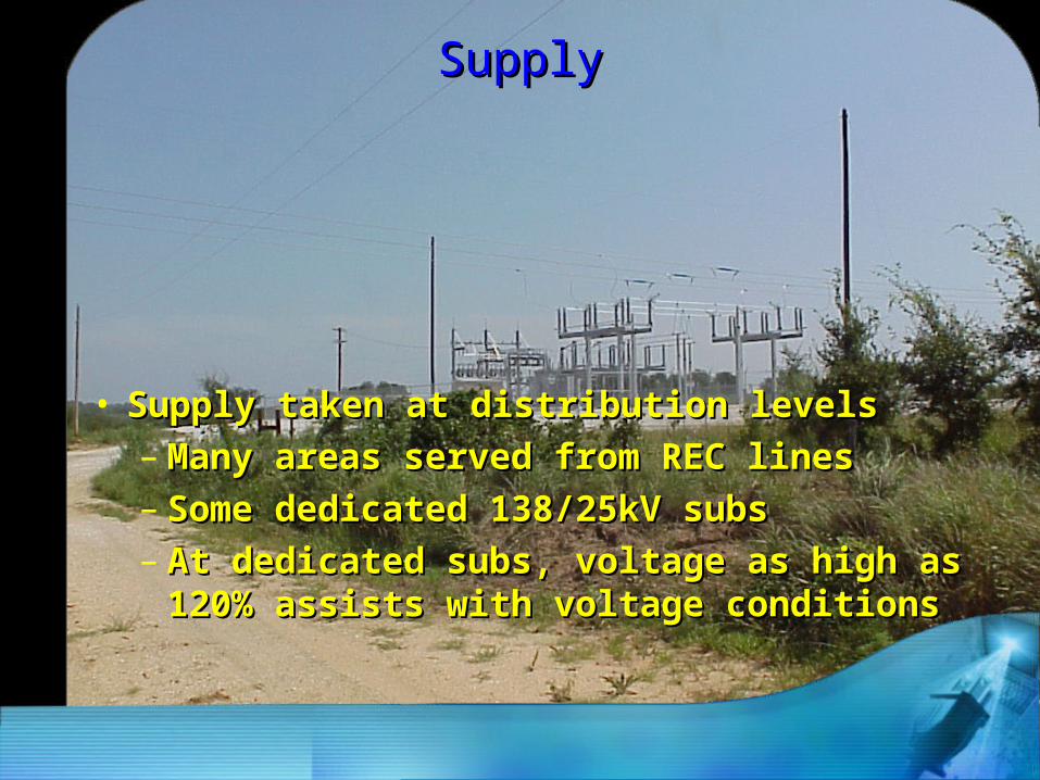
SupplySupply
• Supply taken at distribution levelsSupply taken at distribution levels– Many areas served from REC linesMany areas served from REC lines– Some dedicated 138/25kV subsSome dedicated 138/25kV subs– At dedicated subs, voltage as high as At dedicated subs, voltage as high as
120% assists with voltage conditions120% assists with voltage conditions

Electrical ConstraintsElectrical Constraints
Wire size based on ampacity- SagWire size based on ampacity- Sag
Here, voltage drop is main concernHere, voltage drop is main concern
Low power factor contributesLow power factor contributes
Main trunk line : 477 ACSRMain trunk line : 477 ACSR
Main branch feeders: 4/0 ACSRMain branch feeders: 4/0 ACSR
Individual load service: #2 ACSRIndividual load service: #2 ACSR

CapacitorsCapacitors• With no correction – system at 80% pfWith no correction – system at 80% pf
• Standard – place caps on linesStandard – place caps on lines

CapacitorsCapacitors• Extensive load shedding systemExtensive load shedding system
can trip large quantities of loadcan trip large quantities of load• Resulting excessively leading pfResulting excessively leading pf
can damage equipment, cause tripscan damage equipment, cause trips
• Must switch caps with load shedMust switch caps with load shed• Place oil reclosers or sectionalizersPlace oil reclosers or sectionalizers
at each 25kV cap bankat each 25kV cap bank

CapacitorsCapacitors - Options - Options
• Place mediumPlace mediumvoltage capsvoltage capsat motorsat motors
• AutomaticallyAutomaticallyswitch w/ loadswitch w/ load
• Nearest to loadNearest to load• Can downsizeCan downsize
transformerstransformersand fusesand fuses
• Cost less than Cost less than oil switchesoil switches

Overcurrent ProtectionOvercurrent Protection
• Two unique systemsTwo unique systems– Protect motor & transformer (load point)Protect motor & transformer (load point)– Protect system from cascading faultsProtect system from cascading faults

Overcurrent ProtectionOvercurrent Protection
• Load points protected with fused cutoutsLoad points protected with fused cutouts– Fuse links sized tightly to avoid extra tripsFuse links sized tightly to avoid extra trips– Use high speed (X speed) fuse linksUse high speed (X speed) fuse links

Overcurrent ProtectionOvercurrent ProtectionMain Line CutoutsMain Line Cutouts
• High risk of single phasing motorsHigh risk of single phasing motors• High rating of fuses makes coordinationHigh rating of fuses makes coordination
with utility difficult with utility difficult• Electric storms cause unacceptable # of Electric storms cause unacceptable # of
outages due to arrestor operation outages due to arrestor operation
• Outages require electrician to restore powerOutages require electrician to restore power
= excessive downtime= excessive downtime

Overcurrent ProtectionOvercurrent ProtectionMain Line ReclosersMain Line Reclosers
• Oil reclosers placed at utility supply pointOil reclosers placed at utility supply point
and each main branch feederand each main branch feeder
(2MW or greater load)(2MW or greater load)• Oil reclosers placed along trunk every 10 MWOil reclosers placed along trunk every 10 MW

Overcurrent ProtectionOvercurrent ProtectionMain Line ReclosersMain Line Reclosers
• Main line reclosers use Main line reclosers use processor relaysprocessor relays
• Branch reclosers can use Branch reclosers can use – plug-setting type relays plug-setting type relays processor when availableprocessor when available

LightningLightning
• Lightning is a major concern in this areaLightning is a major concern in this area• 55 isoceraunic days per year 55 isoceraunic days per year
– odds of induced or direct strike highodds of induced or direct strike high
• Lightning arrestors Lightning arrestors – placed every 1500 – 1700 feetplaced every 1500 – 1700 feet
• Excellent ground system is imperativeExcellent ground system is imperative
Effective GroundingEffective Grounding
Multi-point ground required Multi-point ground required Personnel safetyPersonnel safetyEquipment protectionEquipment protection
Length of system #1 factorLength of system #1 factorL of ground wire L of ground wire length lengthLong distance = high ZLong distance = high ZSingle point groundSingle point ground
Does Not ExistDoes Not Exist

Computer Modeling Computer Modeling SelectionSelection
• Cost - $10,000 Cost - $10,000
• Cost - Approximately two weeksCost - Approximately two weeksengineering timeengineering time
• Numerous products on the marketNumerous products on the market
• Two are usable for this type designTwo are usable for this type design
• One was selected based on One was selected based on overhead line modeling capabilitiesoverhead line modeling capabilities

Computer ModelingComputer ModelingProceduresProcedures
• Build single motor model for each service pointBuild single motor model for each service point• Create motor subsystem consisting of Create motor subsystem consisting of
motor, transformer, switches, etcmotor, transformer, switches, etc• Combine several subsystemsCombine several subsystems
on a sub-trunk feederon a sub-trunk feeder

Computer ModelingComputer ModelingProceduresProcedures
• Tie sub-trunk feeders to main trunk lineTie sub-trunk feeders to main trunk line• Add detail for protection devices, fuses, Add detail for protection devices, fuses,
switches, capacitor, microprocessor relays, switches, capacitor, microprocessor relays, motor protection devicesmotor protection devices

FUSE13
FUSE12
CONT5
T6225 kVA
MOTOR1184 HP
FUSE101
CAP27120 kvar
SCHEMATICMOTOR MODEL

Computer ModelingComputer ModelingUsesUses
• Original model created asOriginal model created asdesign tool before any constructiondesign tool before any construction
• Allowed alternatives forAllowed alternatives forconductor size, lengths, protectionconductor size, lengths, protection
• Used model during construction forUsed model during construction for communication with crews communication with crews
Computer ModelingComputer ModelingUsesUses
• Refined model for operations – Refined model for operations –
voltage drop, current, power factor voltage drop, current, power factor • Updated model for system upgradesUpdated model for system upgrades• Recent upgrade netted 8% reductionRecent upgrade netted 8% reduction
in electric bill – 6 month payoutin electric bill – 6 month payout

• Downtime eliminatedDowntime eliminated• Protection system isolates faultsProtection system isolates faults• Total system voltage > 95%Total system voltage > 95%• Contingency is bi-directional feedContingency is bi-directional feed• Adequate Ampacity to prevent sagsAdequate Ampacity to prevent sags
Review GoalsReview Goals

Computer modelingComputer modelingSystem ResultsSystem Results
• Under normal conditions voltage drop is 8%Under normal conditions voltage drop is 8%
• Supply voltages at 115% allow forSupply voltages at 115% allow for continuous operation under contingency continuous operation under contingency
• Advanced coordination of protection allowedAdvanced coordination of protection allowed advanced devices with little on-site prep advanced devices with little on-site prep
• Properly coordinated protection shieldsProperly coordinated protection shields equipment w/o unnecessary downtime equipment w/o unnecessary downtime

• Uncommon: spread out industrial systemUncommon: spread out industrial system• Semi-utility design + uniquely industrial opsSemi-utility design + uniquely industrial ops
• Enhanced specs, > cost, more reliableEnhanced specs, > cost, more reliable• w/o computer, complex system impossiblew/o computer, complex system impossible• Design, construction, operations, mgt.Design, construction, operations, mgt.• One engineerOne engineer
ConclusionsConclusions

ConclusionConclusion
• ConclusivelyConclusivelyWith the aid of modern tools, With the aid of modern tools, a system can be designed thata system can be designed that
* can meet industrial needs * can meet industrial needs * in a utility environment * in a utility environment * with environmental astuteness* with environmental astuteness* by a single engineer* by a single engineer

QUESTIONS?QUESTIONS?


![Vacuum drying chambers - mkparr.com · Vacuum drying chambers | Series VD. 7 . TECHNICAL DATA. Description VD 23 VD 53 VD 115. Measures - Outer dimensions Width net [mm] 515 635 740](https://img.pdfslide.us/doc/110x75/5f9cd02547f36b61d46e5c37/vacuum-drying-chambers-vacuum-drying-chambers-series-vd-7-technical-data.jpg)