Embed Size (px)
Citation preview
INDUSTRIAL CRANE
• • • • • • • • • • • • • • • • • • • • •
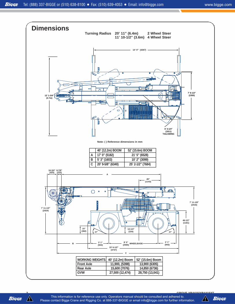
Dimensions
GROVE YB4415/YB4415XT2
6' 3-1/4"(1911)
TAILSWING
7' 8-1/2"(2350)12' 1-3/4"
(3.7m)
14'0" (4267)
15"(382) 27° 27°
13-1/4"(334)
A
8-7/8"(225)
16-3/4"(425)
45"(1143)
7' 11-1/2"(2424)
C
B
15' 6-1/2"(4737)
3' 1"(943)
3' 1"(943)
8' 5"(2565)
46-1/2"(1181)
7' 11-1/8"(2416)
WHEELBASE
Note: ( ) Reference dimensions in mm
Turning Radius 20’ 11” (6.4m) 2 Wheel Steer11’ 10-1/2” (3.6m) 4 Wheel Steer
WORKING WEIGHTS 40’ (12.2m) Boom 52’ (15.6m) BoomFront Axle 11,900, (5398) 13,900 (6305)Rear Axle 15,600 (7076) 14,850 (6736)GVW 27,500 (12,474) 28,750 (13,041)
14’ 0” (4267)
40’ (12.2m) BOOM 52’ (15.6m) BOOMA 17’ 0” (5182) 21’ 5” (6528)B 5’ 3” (1603) 10’ 2” (3099)C 20’ 9-5/8” (6340) 25’ 2-1/2” (7684)
HE
IGH
T F
RO
M G
RO
UN
D IN
FE
ET
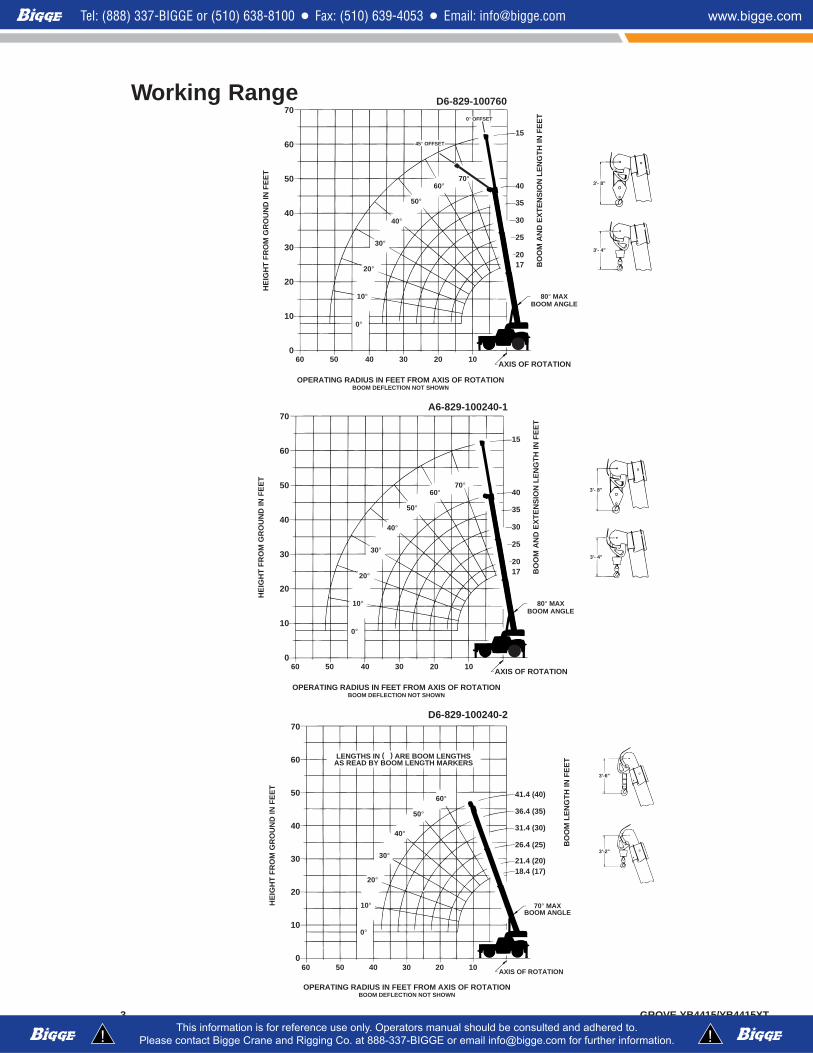
OPERATING RADIUS IN FEET FROM AXIS OF ROTATIONBOOM DEFLECTION NOT SHOWN
70
60
50
40
30
20
10
0
AXIS OF ROTATION
80° MAXBOOM ANGLE
BO
OM
AN
D E
XT
EN
SIO
N L
EN
GT
H IN
FE
ET
5060 40 30 20 10
15
40
35
30
25
2017
70°60°
50°
40°
30°
20°
10°
0°
3'- 8"
3'- 4"
45° OFFSET
0° OFFSET
HE
IGH
T F
RO
M G
RO
UN
D IN
FE
ET
OPERATING RADIUS IN FEET FROM AXIS OF ROTATIONBOOM DEFLECTION NOT SHOWN
70
60
50
40
30
20
10
0
AXIS OF ROTATION
70° MAXBOOM ANGLE
BO
OM
LE
NG
TH
IN F
EE
T
5060 40 30 20 10
41.4 (40)
36.4 (35)
31.4 (30)
26.4 (25)
21.4 (20)18.4 (17)
LENGTHS IN ( ) ARE BOOM LENGTHSAS READ BY BOOM LENGTH MARKERS
60°
50°
40°
30°
20°
10°
0°
3'-6"
3'-2"
GROVE YB4415/YB4415XT3
Working Range D6-829-100760
D6-829-100240-2
HE
IGH
T F
RO
M G
RO
UN
D IN
FE
ET
OPERATING RADIUS IN FEET FROM AXIS OF ROTATIONBOOM DEFLECTION NOT SHOWN
70
60
50
40
30
20
10
0
AXIS OF ROTATION
80° MAXBOOM ANGLE
BO
OM
AN
D E
XT
EN
SIO
N L
EN
GT
H IN
FE
ET
5060 40 30 20 10
15
40
35
30
25
2017
70°60°
50°
40°
30°
20°
10°
0°
3'- 8"
3'- 4"
A6-829-100240-1
GROVE YB4415/YB4415XT4
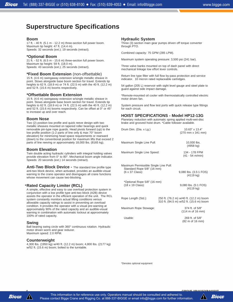
Superstructure Specifications
Boom17 ft. - 40 ft. (5.1 m - 12.2 m) three-section full power boom.Maximum tip height: 47 ft. (14.4 m).Speeds: 32 seconds (ext.); 19 seconds (retract).
*Optional Boom21 ft. - 52 ft. (6.5 m - 15.6 m) three-section full power boom.Maximum tip height: 59 ft. (18.0 m).Speeds: 43 seconds (ext.); 25 seconds (retract).
*Fixed Boom Extension (non-offsettable)15 ft. (4.6 m) swingaway extension w/single metallic sheave inpoint. Stows alongside base boom section for travel. Extends tipheights to 62 ft. (18.9 m) or 74 ft. (22.5 m) with the 40 ft. (12.2 m)and 52 ft. (15.6 m) booms respectively.
*Offsettable Boom Extension15 ft. (4.6 m) swingaway extension w/single metallic sheave inpoint. Stows alongside base boom section for travel. Extends tipheights to 62 ft. (18.9 m) or 74 ft. (22.5 m) with the 40 ft. (12.2 m)and 52 ft. (15.6 m) booms respectively. Can be offset at 0° or 45°to increase up and over reach.
Boom NoseTwo (2) position low profile and quick reeve design with twometallic sheaves mounted on tapered roller bearings and quickremovable pin-type rope guards. Head pivots forward (up) to thelow profile position (1-2 parts of line only & max 70° boomelevation) for minimizing head space requirements or rearward(down) to the conventional position for maximum lifts that exceed 2parts of line reeving or approximately 18,000 lbs. (8165 kg).
Boom ElevationTwin double acting hydraulic cylinders with integral holding valvesprovide elevation from 0° to 80°. Mechanical boom angle indicator.Speeds: 20 seconds (ext.) 14 seconds (retract).
Anti-Two Block Device - The standard low profile typeanti-two block device, when activated, provides an audible-visualwarning to the crane operator and disengages all crane functionswhose movement can cause two-blocking.
Rated Capacity Limiter (RCL)A simple, effective and easy to use overload protection system inconjunction with a low profile type anti-two block (A2B) deviceassists the operator in the efficient operation of the unit. The RCLsystem constantly monitors actual lifting conditions versusallowable capacity ratings to assist in preventing an overloadcondition. It provides the operator with a visual pre-warning atapproximately 90% of the rated capacity and an audible-visualwarning in combination with automatic lockout at approximately100% of rated capacity.
SwingBall bearing swing circle with 360° continuous rotation. Hydraulicmotor driven worm and gear reducer.Maximum speed: 2.0 RPM.
Counterweight4,300 lbs. (1950 kg) w/40 ft. (12.2 m) boom; 4,800 lbs. (2177 kg)w/52 ft. (15.6 m) boom; bolted to the turntable.
Hydraulic SystemThree (3) section main gear pumps driven off torque converterthrough PTO.
Combined capacity: 75 GPM (285 LPM).
Maximum system operating pressure: 3,500 psi (241 bar).
Three valve banks mounted on top of dash panel with directmechanical linkage low effort lever controls.
Return line type filter with full flow by-pass protection and serviceindicator. 10 micron rated replaceable cartridges.
54 gallon (205 L) reservoir with sight level gauge and steel plate toguard against side impact damage.
*Remote-mounted oil cooler with thermostatically controlled electricmotor driven fan.
System pressure and flow test ports with quick release type fittingsfor each circuit.
HOIST SPECIFICATIONS - Model HP12-13GPlanetary reduction with automatic spring applied multi-wet-discbrake and grooved hoist drum. *Cable follower available.
Drum Dim. (Dia. x Lg.) 10.63” x 13.4”(270 mm x 341 mm)
Maximum Single Line Pull: 10,930 lbs.(4958 kg)
Maximum Single Line Speed: 134 - 178 FPM(41 - 54 m/min)
Maximum Permissible Single Line Pull:Standard Rope 5/8” (16 mm) (6 x 37 Class): 9,080 lbs. (3.5:1 FOS)
(4119 kg)
*Optional Rope 5/8” (16 mm) (18 x 19 Class): 9,080 lbs. (5:1 FOS)
(4119 kg)
Rope Length (Std.): 250 ft. (76.2 m) w/40 ft. (12.2 m) boom310 ft. (94.5 m) w/52 ft. (15.6 m) boom
Maximum Rope Stowage: 374 ft. of 5/8”(114 m of 16 mm)
Usable: 269 ft. of 5/8”(82 m of 16 mm)
*Denotes optional equipment
*
5GROVE YB4415/YB4415XT
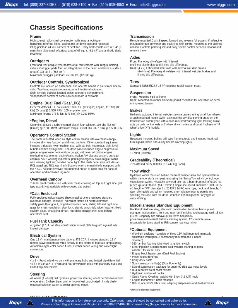
Chassis SpecificationsFrameHigh strength alloy steel construction with integral outriggerhousings; front/rear lifting, towing and tie down lugs and recessedlifting points in all four corners of deck top. Carry deck constructed of 1/4” (6mm) thick plate steel w/surface area of 66 sq. ft. (6.1 m2) and anti-skid decktreatment.
OutriggersFront and rear oblique type beams at all four corners with integral holdingvalves. Outrigger pads form an integral part of the beam and have a surfacearea of 103 sq. in. (665 cm2).Maximum outrigger pad load: 26,539 lbs. (12 038 kg).
Outrigger Controls, SynchronizedControls are located on dash panel and operate beams in pairs from side toside. Two hand sequence minimizes unintentional actuation.Sight leveling bubbles located inside operator’s compartment.*Independent control of each individual beam is available.
Engine, Dual Fuel (Gas/LPG)General Motors 4.3 L, six cylinder, dual fuel (LPG/gas) engine, 115 bhp (85kW) (Gross) @ 2,500 RPM. 100 amp alternator.Maximum torque: 275 ft. lbs. (373 Nm) @ 2,200 RPM.
*Engine, DieselCummins 4BT3.9 L turbo-charged diesel, four cylinder, 110 bhp (82 kW)(Gross) @ 2,500 RPM. Maximum torque: 293 ft. lbs. (397 Nm) @ 1,500 RPM.
Operator’s Control StationThe frame mounted, open air style control station with overhead canopyincludes all crane function and driving controls. Other standard equipmentincludes a durable nylon cushion seat with lap belt; hourmeter; sight levelbubble and fire extinguisher. The dash panel includes engine oil pressuregauge; engine water temperature gauge; voltmeter; all critical enginemonitoring instruments; engine/transmission A/V distress system; outriggercontrols; *A2B warning indicators; parking/emergency brake toggle switchwith warning light and hooded panel light. The dash panel also includes anRCL panel and RCL warning indicators when the machine is equipped withthe *RCL. All control valves are mounted on top of dash area for ease ofoperation and increased leg room.
Overhead CanopyTubular steel construction with steel mesh covering on top and right side grilltype guard. Not available with enclosed cab option.
*Cab, EnclosedFully enclosed galvannealed sheet metal structure replaces standardoverhead canopy. Includes hot water forced air heater/defroster,safety glass throughout, hinged removable door, sliding left and right sideglass for cross ventilation, door lock, electric windshield wiper/ washer, fixedskylight glass, circulating air fan, rear deck storage shelf area behindoperator’s seat.
Fuel Tank Capacity46 gallon (175 L) all steel construction w/steel plate to guard against sideimpact damage.
Electrical SystemOne 12 V - maintenance free battery. 875 CCA. Includes standard 12 Vremote slave receptacle wired directly to the starter to facilitate jump starting.Automotive type color coded fuses, number coded wiring and water tightconnectors.
Drive4 x 2 - Front axle drive only with planetary hubs and limited slip differential.*4 x 4 (YB4415XT) - Front and rear drive/steer axles with planetary hubs andlimited slip differentials.
SteeringAll wheel (4 wheel), full hydraulic power via steering wheel permits two modesof operation: 2 wheel (rear only) or four-wheel coordinated. Inside dash-mounted selector switch to select steering mode.
TransmissionRemote mounted Clark 3 speed forward and reverse full powershift w/enginemounted torque converter and stalk type shift control mounted to the steeringcolumn. Controls permit quick and easy shuttle control between forward andreverse travel.
AxlesFront: Planetary drive/steer with internalmulti-wet-disc brakes and limited slip differential.Rear: (4 x 2) Fabricated steer axle with internal wet disc brakes.
(4x4 drive) Planetary drive/steer with internal wet disc brakes andlimited slip differential.
TiresStandard 385/65R22.5-18 PR tubeless radial traction tread.
SuspensionFront: Mounted rigid to frame.Rear: Mounted on rubber blocks to permit oscillation for operation on semi-unimproved terrain.
BrakesHydraulic actuated internal wet-disc service brakes acting on all four wheels.A dash mounted toggle switch activates the dry disc parking brake on thetransmission output yoke with a dash mounted warning light. Parking brakeacts on both front wheels of 2 wheel drive models and on all 4 wheels of *4wheel drive (XT) models.
LightsRecessed mounted behind grill type frame cutouts and includes head, tail,turn signals, brake and 4-way hazard warning lights.
Maximum Speed19 MPH (30 kph)
Gradeability (Theoretical)75% (Based on 27,000 lbs. [12 247 kg] GVW).
*Tow WinchHydraulic winch mounted behind the front bumper area and operated fromwithin the operator’s compartment using the Swing/Tow winch control levervia selector switch. Hydraulic powered unit has a bare drum pull of 6,000 lbs.(2722 kg) at 48 ft./min. (14.6 m/min.) single line speed. Includes 100 ft. (30.5m) length of 3/8” diameter 6 x 25 EIPS IWRC wire rope, hook and thimble, 4way roller guide and winch mounted drum release lever to permit freespooling the rope from the drum. Winch is not designed for any type ofvertical lifting.
Miscellaneous Standard EquipmentHookblock tiedown sling, electronic combination two-tone back-up andoutrigger motion alarm, front and rear running lights, tool stowage well, 15 ton(15 MT) capacity two sheave quick reeve hookblock,powertrain audio-visual distress warning system, 12 V remote slavereceptacle for jump starting, R/S convex rearview mirror.
*Optional Equipment* Worklight package - consists of three 12V, ball mounted, manually
adjustable worklights (2-cab/canopy mounted and 1 boommounted)
* 360° amber flashing light wired to ignition switch* Ether injection & block heater cold weather starting kit (less
canister) for diesel only* Engine block heater only (Dual Fuel Engine)* Pintle hooks front/rear* Carry deck posts* Spark arrestor muffler(s) (Dual Fuel only)* Sound suppression package for under 90 dBa cab noise levels * Dual rearview west coast mirrors* Hydraulic system oil cooler* Quick Reeve Overhaul weight with 5 ton (4.5 MT) hook* Engine tachometer, dash mounted* Deluxe operator’s fabric seat w/spring suspension and dual armrests
*Denotes optional equipment
GROVE YB4415/YB4415XT6
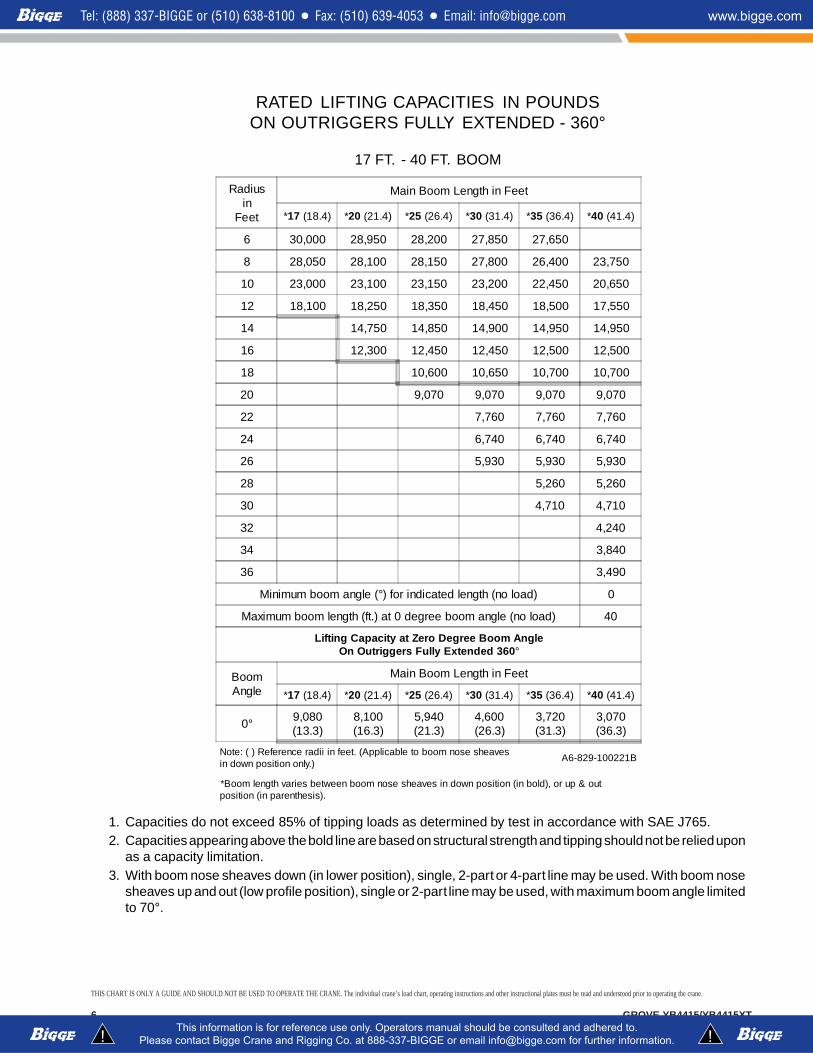
RATED LIFTING CAPACITIES IN POUNDSON OUTRIGGERS FULLY EXTENDED - 360°
17 FT. - 40 FT. BOOM
1. Capacities do not exceed 85% of tipping loads as determined by test in accordance with SAE J765.2. Capacities appearing above the bold line are based on structural strength and tipping should not be relied upon
as a capacity limitation.3. With boom nose sheaves down (in lower position), single, 2-part or 4-part line may be used. With boom nose
sheaves up and out (low profile position), single or 2-part line may be used, with maximum boom angle limitedto 70°.
Radiusin
Feet
Main Boom Length in Feet
*17 (18.4) *20 (21.4) *25 (26.4) *30 (31.4) *35 (36.4) *40 (41.4)
6 30,000 28,950 28,200 27,850 27,650
8 28,050 28,100 28,150 27,800 26,400 23,750
10 23,000 23,100 23,150 23,200 22,450 20,650
12 18,100 18,250 18,350 18,450 18,500 17,550
14 14,750 14,850 14,900 14,950 14,950
16 12,300 12,450 12,450 12,500 12,500
18 10,600 10,650 10,700 10,700
20 9,070 9,070 9,070 9,070
22 7,760 7,760 7,760
24 6,740 6,740 6,740
26 5,930 5,930 5,930
28 5,260 5,260
30 4,710 4,710
32 4,240
34 3,840
36 3,490
Minimum boom angle (°) for indicated length (no load) 0
Maximum boom length (ft.) at 0 degree boom angle (no load) 40
Lifting Capacity at Zero Degree Boom AngleOn Outriggers Fully Extended 360°
BoomAngle
Main Boom Length in Feet
*17 (18.4) *20 (21.4) *25 (26.4) *30 (31.4) *35 (36.4) *40 (41.4)
0° 9,080(13.3)
8,100(16.3)
5,940(21.3)
4,600(26.3)
3,720(31.3)
3,070(36.3)
Note: ( ) Reference radii in feet. (Applicable to boom nose sheavesin down position only.)
A6-829-100221B
*Boom length varies between boom nose sheaves in down position (in bold), or up & outposition (in parenthesis).
THIS CHART IS ONLY A GUIDE AND SHOULD NOT BE USED TO OPERATE THE CRANE. The individual crane’s load chart, operating instructions and other instructional plates must be read and understood prior to operating the crane.
7GROVE YB4415/YB4415XT
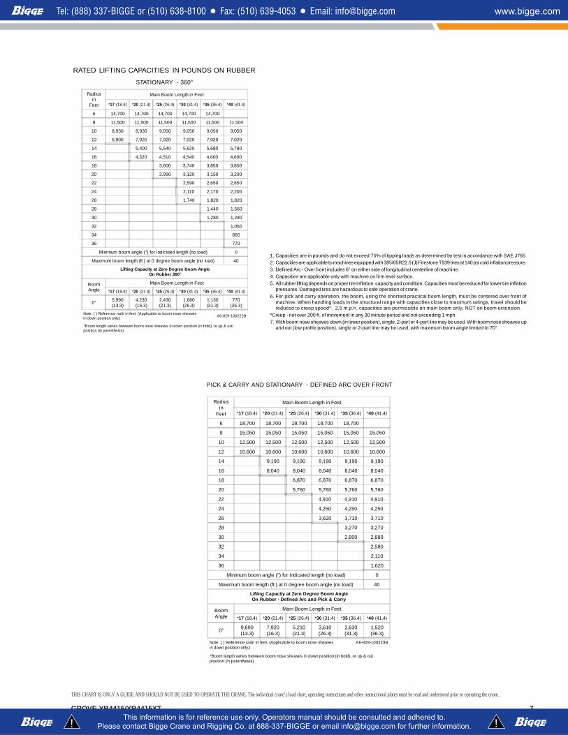
RATED LIFTING CAPACITIES IN POUNDS ON RUBBER
STATIONARY - 360°
Radiusin
Feet
Main Boom Length in Feet
*17 (18.4) *20 (21.4) *25 (26.4) *30 (31.4) *35 (36.4) *40 (41.4)
6 14,700 14,700 14,700 14,700 14,700
8 11,500 11,500 11,500 11,500 11,500 11,500
10 8,930 8,930 9,050 9,050 9,050 9,050
12 6,900 7,020 7,020 7,020 7,020 7,020
14 5,400 5,540 5,620 5,680 5,780
16 4,320 4,510 4,540 4,600 4,600
18 3,600 3,740 3,850 3,850
20 2,990 3,120 3,150 3,200
22 2,590 2,650 2,650
24 2,110 2,170 2,200
26 1,740 1,820 1,820
28 1,440 1,560
30 1,280 1,280
32 1,060
34 860
36 770
Minimum boom angle (°) for indicated length (no load) 0
Maximum boom length (ft.) at 0 degree boom angle (no load) 40
Lifting Capacity at Zero Degree Boom AngleOn Rubber 360°
BoomAngle
Main Boom Length in Feet
*17 (18.4) *20 (21.4) *25 (26.4) *30 (31.4) *35 (36.4) *40 (41.4)
0° 5,990(13.3)
4,230(16.3)
2,430(21.3)
1,680(26.3)
1,130(31.3)
770(36.3)
Note: ( ) Reference radii in feet. (Applicable to boom nose sheavesin down position only.)
A6-829-100222B
*Boom length varies between boom nose sheaves in down position (in bold), or up & outposition (in parenthesis).
1. Capacities are in pounds and do not exceed 75% of tipping loads as determined by test in accordance with SAE J765.2. Capacities are applicable to machines equipped with 385/65R22.5 (J) Firestone T839 tires at 140 psi cold inflation pressure.3. Defined Arc - Over front includes 6° on either side of longitudinal centerline of machine.4. Capacities are applicable only with machine on firm level surface.5. All rubber lifting depends on proper tire inflation, capacity and condition. Capacities must be reduced for lower tire inflation
pressures. Damaged tires are hazardous to safe operation of crane.6. For pick and carry operation, the boom, using the shortest practical boom length, must be centered over front of
machine. When handling loads in the structural range with capacities close to maximum ratings, travel should bereduced to creep speed*. 2.5 m.p.h. capacities are permissible on main boom only, NOT on boom extension.
*Creep - not over 200 ft. of movement in any 30 minute period and not exceeding 1 mph.7. With boom nose sheaves down (in lower position), single, 2-part or 4-part line may be used. With boom nose sheaves up
and out (low profile position), single or 2-part line may be used, with maximum boom angle limited to 70°.
PICK & CARRY AND STATIONARY - DEFINED ARC OVER FRONT
Radiusin
Feet
Main Boom Length in Feet
*17 (18.4) *20 (21.4) *25 (26.4) *30 (31.4) *35 (36.4) *40 (41.4)
6 18,700 18,700 18,700 18,700 18,700
8 15,050 15,050 15,050 15,050 15,050 15,050
10 12,500 12,500 12,500 12,500 12,500 12,500
12 10,600 10,600 10,600 10,600 10,600 10,600
14 9,190 9,190 9,190 9,190 9,190
16 8,040 8,040 8,040 8,040 8,040
18 6,870 6,870 6,870 6,870
20 5,760 5,760 5,760 5,760
22 4,910 4,910 4,910
24 4,250 4,250 4,250
26 3,620 3,710 3,710
28 3,270 3,270
30 2,800 2,880
32 2,580
34 2,110
36 1,620
Minimum boom angle (°) for indicated length (no load) 0
Maximum boom length (ft.) at 0 degree boom angle (no load) 40
Lifting Capacity at Zero Degree Boom AngleOn Rubber - Defined Arc and Pick & Carry
BoomAngle
Main Boom Length in Feet
*17 (18.4) *20 (21.4) *25 (26.4) *30 (31.4) *35 (36.4) *40 (41.4)
0° 9,690(13.3)
7,920(16.3)
5,210(21.3)
3,610(26.3)
2,630(31.3)
1,520(36.3)
Note: ( ) Reference radii in feet. (Applicable to boom nose sheavesin down position only.)
A6-829-100223B
*Boom length varies between boom nose sheaves in down position (in bold), or up & outposition (in parenthesis).
THIS CHART IS ONLY A GUIDE AND SHOULD NOT BE USED TO OPERATE THE CRANE. The individual crane’s load chart, operating instructions and other instructional plates must be read and understood prior to operating the crane.
GROVE YB4415/YB4415XT8
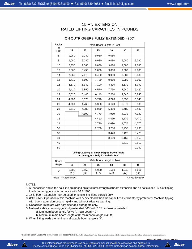
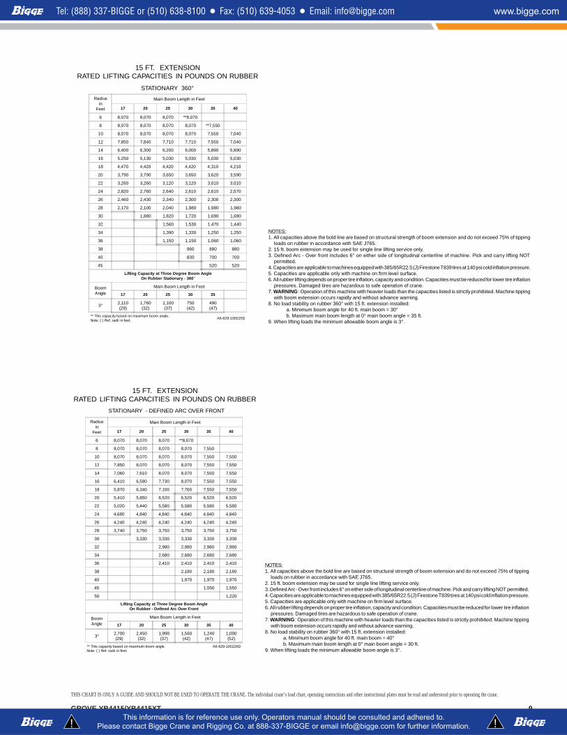
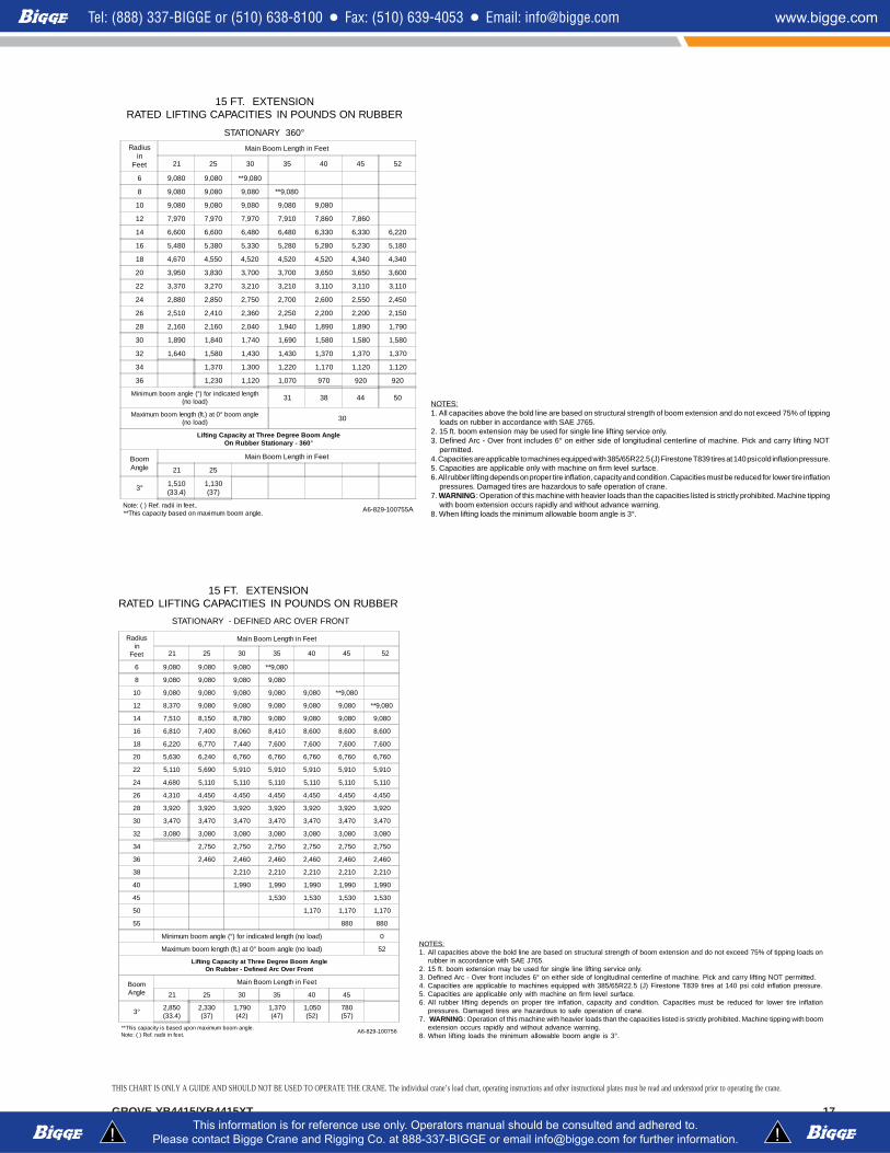
15 FT. EXTENSIONRATED LIFTING CAPACITIES IN POUNDS
ON OUTRIGGERS FULLY EXTENDED - 360°
NOTES:1. All capacities above the bold line are based on structural strength of boom extension and do not exceed 85% of tipping
loads on outriggers in accordance with SAE J765.2. 15 ft. boom extension may be used for single line lifting service only.3. WARNING: Operation of this machine with heavier loads than the capacities listed is strictly prohibited. Machine tipping
with boom extension occurs rapidly and without advance warning.4. Capacities listed are with fully extended outriggers only.5. No load stability on outriggers fully extended 360° with 15 ft. extension installed:
a. Minimum boom angle for 40 ft. main boom = 0°b. Maximum main boom length at 0° main boom angle = 40 ft.
6. When lifting loads the minimum allowable boom angle is 3°.
Radiusin
Feet
Main Boom Length in Feet
17 20 25 30 35 40
6 9,080 9,080 9,080 9,080
8 9,080 9,080 9,080 9,080 9,080 9,080
10 8,850 9,080 9,080 9,080 9,080 9,080
12 7,860 8,450 9,080 9,080 9,080 9,080
14 7,060 7,610 8,480 9,080 9,080 9,080
16 6,410 6,590 7,730 9,080 9,080 8,900
18 5,870 6,340 7,100 8,390 8,330 8,090
20 5,410 5,850 6,570 7,750 7,640 7,420
22 5,020 5,440 6,110 7,260 7,040 6,840
24 4,680 5,070 5,710 6,720 6,530 6,340
26 4,380 4,760 5,360 6,140 6,070 5,900
28 3,740 4,380 5,050 5,480 5,480 5,480
30 4,190 4,770 4,930 4,930 4,930
32 4,410 4,470 4,470 4,470
34 3,790 4,070 4,070 4,070
36 2,730 3,730 3,730 3,730
38 3,420 3,420 3,420
40 3,160 3,160 3,160
45 2,610 2,610
50 2,190
Lifting Capacity at Three Degree Boom AngleOn Outriggers Fully Extended - 360°
BoomAngle
Main Boom Length in Feet
17 20 25 30 35 40
3° 2,700(29)
2,450(32)
1,990(37)
1,560(42)
1,240(47)
1,000(52)
Note: ( ) Ref. radii in feet. A6-829-100224D
THIS CHART IS ONLY A GUIDE AND SHOULD NOT BE USED TO OPERATE THE CRANE. The individual crane’s load chart, operating instructions and other instructional plates must be read and understood prior to operating the crane.
9GROVE YB4415/YB4415XT
15 FT. EXTENSIONRATED LIFTING CAPACITIES IN POUNDS ON RUBBER
STATIONARY 360°Radius
inFeet
Main Boom Length in Feet
17 20 25 30 35 40
6 8,070 8,070 8,070 **8,070
8 8,070 8,070 8,070 8,070 **7,550
10 8,070 8,070 8,070 8,070 7,550 7,040
12 7,850 7,840 7,710 7,710 7,550 7,040
14 6,400 6,300 6,200 6,000 5,890 5,890
16 5,250 5,130 5,030 5,030 5,030 5,030
18 4,470 4,420 4,420 4,420 4,310 4,210
20 3,790 3,790 3,650 3,650 3,620 3,590
22 3,260 3,260 3,120 3,120 3,010 3,010
24 2,820 2,760 2,640 2,610 2,610 2,570
26 2,460 2,430 2,340 2,300 2,300 2,300
28 2,170 2,100 2,040 1,980 1,980 1,980
30 1,880 1,820 1,720 1,690 1,690
32 1,560 1,530 1,470 1,440
34 1,390 1,330 1,250 1,250
36 1,150 1,150 1,060 1,060
38 960 880 880
40 830 700 700
45 520 520
Lifting Capacity at Three Degree Boom AngleOn Rubber Stationary - 360°
BoomAngle
Main Boom Length in Feet
17 20 25 30 35
3° 2,110(29)
1,760(32)
1,100(37)
750(42)
490(47)
** This capacity based on maximum boom angle.Note: ( ) Ref. radii in feet.
A6-829-100225D
NOTES:1. All capacities above the bold line are based on structural strength of boom extension and do not exceed 75% of tipping
loads on rubber in accordance with SAE J765.2. 15 ft. boom extension may be used for single line lifting service only.3. Defined Arc - Over front includes 6° on either side of longitudinal centerline of machine. Pick and carry lifting NOT
permitted.4. Capacities are applicable to machines equipped with 385/65R22.5 (J) Firestone T839 tires at 140 psi cold inflation pressure.5. Capacities are applicable only with machine on firm level surface.6. All rubber lifting depends on proper tire inflation, capacity and condition. Capacities must be reduced for lower tire inflation
pressures. Damaged tires are hazardous to safe operation of crane.7. WARNING: Operation of this machine with heavier loads than the capacities listed is strictly prohibited. Machine tipping
with boom extension occurs rapidly and without advance warning.8. No load stability on rubber 360° with 15 ft. extension installed:
a. Minimum boom angle for 40 ft. main boom = 30°b. Maximum main boom length at 0° main boom angle = 35 ft.
9. When lifting loads the minimum allowable boom angle is 3°.
15 FT. EXTENSIONRATED LIFTING CAPACITIES IN POUNDS ON RUBBER
STATIONARY - DEFINED ARC OVER FRONT
Radiusin
Feet
Main Boom Length in Feet
17 20 25 30 35 40
6 8,070 8,070 8,070 **8,070
8 8,070 8,070 8,070 8,070 7,550
10 8,070 8,070 8,070 8,070 7,550 7,550
12 7,850 8,070 8,070 8,070 7,550 7,550
14 7,060 7,610 8,070 8,070 7,550 7,550
16 6,410 6,590 7,730 8,070 7,550 7,550
18 5,870 6,340 7,100 7,760 7,550 7,550
20 5,410 5,850 6,520 6,520 6,520 6,520
22 5,020 5,440 5,580 5,580 5,580 5,580
24 4,680 4,840 4,840 4,840 4,840 4,840
26 4,240 4,240 4,240 4,240 4,240 4,240
28 3,740 3,750 3,750 3,750 3,750 3,750
30 3,330 3,330 3,330 3,330 3,330
32 2,980 2,980 2,980 2,980
34 2,680 2,680 2,680 2,680
36 2,410 2,410 2,410 2,410
38 2,180 2,180 2,180
40 1,970 1,970 1,970
45 1,550 1,550
50 1,220
Lifting Capacity at Three Degree Boom AngleOn Rubber - Defined Arc Over Front
BoomAngle
Main Boom Length in Feet
17 20 25 30 35 40
3° 2,700(29)
2,450(32)
1,990(37)
1,560(42)
1,240(47)
1,000(52)
** This capacity based on maximum boom angle.Note: ( ) Ref. radii in feet.
A6-829-100226D
NOTES:1. All capacities above the bold line are based on structural strength of boom extension and do not exceed 75% of tipping
loads on rubber in accordance with SAE J765.2. 15 ft. boom extension may be used for single line lifting service only.3. Defined Arc - Over front includes 6° on either side of longitudinal centerline of machine. Pick and carry lifting NOT permitted.4. Capacities are applicable to machines equipped with 385/65R22.5 (J) Firestone T839 tires at 140 psi cold inflation pressure.5. Capacities are applicable only with machine on firm level surface.6. All rubber lifting depends on proper tire inflation, capacity and condition. Capacities must be reduced for lower tire inflation
pressures. Damaged tires are hazardous to safe operation of crane.7. WARNING: Operation of this machine with heavier loads than the capacities listed is strictly prohibited. Machine tipping
with boom extension occurs rapidly and without advance warning.8. No load stability on rubber 360° with 15 ft. extension installed:
a. Minimum boom angle for 40 ft. main boom = 40°b. Maximum main boom length at 0° main boom angle = 30 ft.
9. When lifting loads the minimum allowable boom angle is 3°.
THIS CHART IS ONLY A GUIDE AND SHOULD NOT BE USED TO OPERATE THE CRANE. The individual crane’s load chart, operating instructions and other instructional plates must be read and understood prior to operating the crane.
GROVE YB4415/YB4415XT10
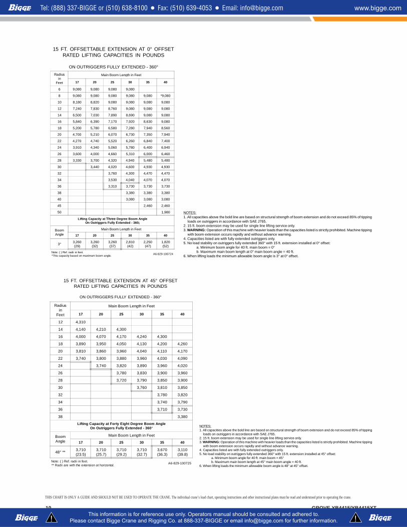
15 FT. OFFSETTABLE EXTENSION AT 0° OFFSETRATED LIFTING CAPACITIES IN POUNDS
ON OUTRIGGERS FULLY EXTENDED - 360°
Radiusin
Feet
Main Boom Length in Feet
17 20 25 30 35 40
6 9,080 9,080 9,080 9,080
8 9,080 9,080 9,080 9,080 9,080 *9,080
10 8,180 8,820 9,080 9,080 9,080 9,080
12 7,240 7,830 8,760 9,080 9,080 9,080
14 6,500 7,030 7,890 8,690 9,080 9,080
16 5,840 6,390 7,170 7,920 8,630 9,080
18 5,200 5,780 6,580 7,280 7,940 8,560
20 4,700 5,210 6,070 6,730 7,350 7,940
22 4,270 4,740 5,520 6,260 6,840 7,400
24 3,910 4,340 5,060 5,780 6,400 6,940
26 3,600 4,000 4,660 5,310 6,000 6,460
28 3,330 3,700 4,320 4,940 5,480 5,480
30 3,440 4,020 4,600 4,930 4,930
32 3,760 4,300 4,470 4,470
34 3,530 4,040 4,070 4,070
36 3,310 3,730 3,730 3,730
38 3,380 3,380 3,380
40 3,080 3,080 3,080
45 2,460 2,460
50 1,980
Lifting Capacity at Three Degree Boom AngleOn Outriggers Fully Extended - 360¡
BoomAngle
Main Boom Length in Feet
17 20 25 30 35 40
3° 3,260(29)
3,260(32)
3,260(37)
2,810(42)
2,250(47)
1,820(52)
Note: ( ) Ref. radii in feet.*This capacity based on maximum boom angle.
A6-829-100724
NOTES:1. All capacities above the bold line are based on structural strength of boom extension and do not exceed 85% of tipping
loads on outriggers in accordance with SAE J765.2. 15 ft. boom extension may be used for single line lifting service only.3. WARNING: Operation of this machine with heavier loads than the capacities listed is strictly prohibited. Machine tipping
with boom extension occurs rapidly and without advance warning.4. Capacities listed are with fully extended outriggers only.5. No load stability on outriggers fully extended 360° with 15 ft. extension installed at 0° offset:
a. Minimum boom angle for 40 ft. main boom = 0°b. Maximum main boom length at 0° main boom angle = 40 ft.
6. When lifting loads the minimum allowable boom angle is 3° at 0° offset.
15 FT. OFFSETTABLE EXTENSION AT 45° OFFSETRATED LIFTING CAPACITIES IN POUNDS
ON OUTRIGGERS FULLY EXTENDED - 360°
Radiusin
Feet
Main Boom Length in Feet
17 20 25 30 35 40
12 4,310
14 4,140 4,210 4,300
16 4,000 4,070 4,170 4,240 4,300
18 3,890 3,950 4,050 4,130 4,200 4,260
20 3,810 3,860 3,960 4,040 4,110 4,170
22 3,740 3,800 3,880 3,960 4,030 4,090
24 3,740 3,820 3,890 3,960 4,020
26 3,780 3,830 3,900 3,960
28 3,720 3,790 3,850 3,900
30 3,760 3,810 3,850
32 3,780 3,820
34 3,740 3,790
36 3,710 3,730
38 3,380
Lifting Capacity at Forty Eight Degree Boom AngleOn Outriggers Fully Extended - 360°
BoomAngle
Main Boom Length in Feet
17 20 25 30 35 40
48° ** 3,710(23.5)
3,710(25.7)
3,710(29.2)
3,710(32.7)
3,670(36.3)
3,110(39.8)
Note: ( ) Ref. radii in feet.** Radii are with the extension at horizontal.
A6-829-100725
NOTES:1. All capacities above the bold line are based on structural strength of boom extension and do not exceed 85% of tipping
loads on outriggers in accordance with SAE J765.2. 15 ft. boom extension may be used for single line lifting service only.3. WARNING: Operation of this machine with heavier loads than the capacities listed is strictly prohibited. Machine tipping
with boom extension occurs rapidly and without advance warning.4. Capacities listed are with fully extended outriggers only.5. No load stability on outriggers fully extended 360° with 15 ft. extension installed at 45° offset:
a. Minimum boom angle for 40 ft. main boom = 45°b. Maximum main boom length at 45° main boom angle = 40 ft.
6. When lifting loads the minimum allowable boom angle is 48° at 45° offset.
THIS CHART IS ONLY A GUIDE AND SHOULD NOT BE USED TO OPERATE THE CRANE. The individual crane’s load chart, operating instructions and other instructional plates must be read and understood prior to operating the crane.
11GROVE YB4415/YB4415XT
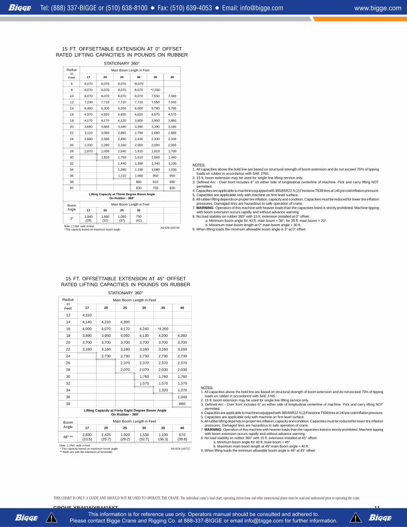
15 FT. OFFSETTABLE EXTENSION AT 0° OFFSETRATED LIFTING CAPACITIES IN POUNDS ON RUBBER
STATIONARY 360°Radius
inFeet
Main Boom Length in Feet
17 20 25 30 35 40
6 8,070 8,070 8,070 *8,070
8 8,070 8,070 8,070 8,070 *7,550
10 8,070 8,070 8,070 8,070 7,550 7,040
12 7,240 7,710 7,710 7,710 7,550 7,040
14 6,400 6,300 6,200 6,000 5,780 5,780
16 4,970 4,920 4,920 4,620 4,570 4,570
18 4,170 4,170 4,120 3,900 3,900 3,860
20 3,660 3,660 3,440 3,390 3,390 3,180
22 3,110 3,060 2,960 2,790 2,680 2,680
24 2,680 2,580 2,490 2,430 2,330 2,330
26 2,330 2,280 2,160 2,000 2,000 2,000
28 2,070 2,050 2,040 1,910 1,810 1,700
30 1,810 1,750 1,610 1,560 1,440
32 1,440 1,390 1,340 1,230
34 1,260 1,190 1,080 1,030
36 1,110 1,060 950 950
38 860 810 690
40 830 700 600
Lifting Capacity at Three Degree Boom AngleOn Rubber - 360°
BoomAngle
Main Boom Length in Feet
17 20 25 30
3° 1,940(29)
1,660(32)
1,080(37)
750(42)
Note: ( ) Ref. radii in feet.*This capacity based on maximum boom angle.
A6-829-100726
NOTES:1. All capacities above the bold line are based on structural strength of boom extension and do not exceed 75% of tipping
loads on rubber in accordance with SAE J765.2. 15 ft. boom extension may be used for single line lifting service only.3. Defined Arc - Over front includes 6° on either side of longitudinal centerline of machine. Pick and carry lifting NOT
permitted.4. Capacities are applicable to machines equipped with 385/65R22.5 (J) Firestone T839 tires at 140 psi cold inflation pressure.5. Capacities are applicable only with machine on firm level surface.6. All rubber lifting depends on proper tire inflation, capacity and condition. Capacities must be reduced for lower tire inflation
pressures. Damaged tires are hazardous to safe operation of crane.7. WARNING: Operation of this machine with heavier loads than the capacities listed is strictly prohibited. Machine tipping
with boom extension occurs rapidly and without advance warning.8. No load stability on rubber 360° with 15 ft. extension installed at 0° offset:
a. Minimum boom angle for 40 ft. main boom = 38°; for 35 ft. main boom = 20°b. Maximum main boom length at 0° main boom angle = 30 ft.
9. When lifting loads the minimum allowable boom angle is 3° at 0° offset.
15 FT. OFFSETTABLE EXTENSION AT 45° OFFSETRATED LIFTING CAPACITIES IN POUNDS ON RUBBER
STATIONARY 360°Radius
inFeet
Main Boom Length in Feet
17 20 25 30 35 40
12 4,310
14 4,140 4,210 4,300
16 4,000 4,070 4,170 4,240 *4,300
18 3,890 3,950 4,050 4,130 4,200 4,260
20 3,700 3,700 3,700 3,700 3,700 3,700
22 3,160 3,160 3,160 3,160 3,160 3,160
24 2,730 2,730 2,730 2,730 2,730
26 2,370 2,370 2,370 2,370
28 2,070 2,070 2,030 2,030
30 1,760 1,760 1,760
32 1,570 1,570 1,570
34 1,320 1,270
36 1,040
38 860
Lifting Capacity at Forty Eight Degree Boom AngleOn Rubber - 360°
BoomAngle
Main Boom Length in Feet
17 20 25 30 35 40
48° ** 2,830(23.5)
2,425(25.7)
1,920(29.2)
1,530(32.7)
1,100(36.3)
670(39.8)
Note: ( ) Ref. radii in feet.* This capacity based on maximum boom angle.** Radii are with the extension at horizontal.
A6-829-100727
NOTES:1. All capacities above the bold line are based on structural strength of boom extension and do not exceed 75% of tipping
loads on rubber in accordance with SAE J765.2. 15 ft. boom extension may be used for single line lifting service only.3. Defined Arc - Over front includes 6° on either side of longitudinal centerline of machine. Pick and carry lifting NOT
permitted.4. Capacities are applicable to machines equipped with 385/65R22.5 (J) Firestone T839 tires at 140 psi cold inflation pressure.5. Capacities are applicable only with machine on firm level surface.6. All rubber lifting depends on proper tire inflation, capacity and condition. Capacities must be reduced for lower tire inflation
pressures. Damaged tires are hazardous to safe operation of crane.7. WARNING: Operation of this machine with heavier loads than the capacities listed is strictly prohibited. Machine tipping
with boom extension occurs rapidly and without advance warning.8. No load stability on rubber 360° with 15 ft. extension installed at 45° offset:
a. Minimum boom angle for 40 ft. main boom = 45°b. Maximum main boom length at 45° main boom angle = 40 ft.
9. When lifting loads the minimum allowable boom angle is 48° at 45° offset.
THIS CHART IS ONLY A GUIDE AND SHOULD NOT BE USED TO OPERATE THE CRANE. The individual crane’s load chart, operating instructions and other instructional plates must be read and understood prior to operating the crane.
12 GROVE YB4415/YB4415XT
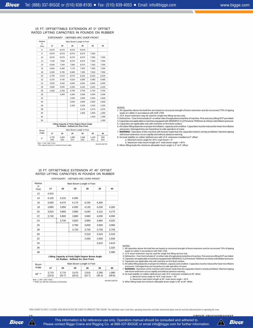
15 FT. OFFSETTABLE EXTENSION AT 0° OFFSETRATED LIFTING CAPACITIES IN POUNDS ON RUBBER
STATIONARY - DEFINED ARC OVER FRONT
Radiusin
Feet
Main Boom Length in Feet
17 20 25 30 35 40
6 8,070 8,070 8,070 *8,070
8 8,070 8,070 8,070 8,070 7,550
10 8,070 8,070 8,070 8,070 7,550 7,550
12 7,240 7,830 8,070 8,070 7,550 7,550
14 6,500 7,030 7,890 8,070 7,550 7,550
16 5,840 6,390 7,170 7,920 7,550 7,550
18 5,200 5,780 6,580 7,280 7,550 7,550
20 4,700 5,210 6,070 6,520 6,520 6,520
22 4,270 4,740 5,520 5,580 5,580 5,580
24 3,910 4,340 4,840 4,840 4,840 4,840
26 3,600 4,000 4,240 4,240 4,240 4,240
28 3,330 3,700 3,750 3,750 3,750 3,750
30 3,300 3,300 3,300 3,300 3,300
32 2,930 2,930 2,930 2,930
34 2,600 2,600 2,600 2,600
36 2,320 2,320 2,320 2,320
38 2,070 2,070 2,070
40 1,850 1,850 1,850
45 1,400 1,400
50 1,050
Lifting Capacity at Three Degree Boom AngleOn Rubber - Defined Arc Over Front
BoomAngle
Main Boom Length in Feet
17 20 25 30 35 40
3° 2,700(29)
2,450(32)
1,990(37)
1,560(42)
1,240(47)
930(52)
Note: ( ) Ref. radii in feet.*This capacity based on maximum boom angle.
A6-829-100728
NOTES:1. All capacities above the bold line are based on structural strength of boom extension and do not exceed 75% of tipping
loads on rubber in accordance with SAE J765.2. 15 ft. boom extension may be used for single line lifting service only.3. Defined Arc - Over front includes 6° on either side of longitudinal centerline of machine. Pick and carry lifting NOT permitted.4. Capacities are applicable to machines equipped with 385/65R22.5 (J) Firestone T839 tires at 140 psi cold inflation pressure.5. Capacities are applicable only with machine on firm level surface.6. All rubber lifting depends on proper tire inflation, capacity and condition. Capacities must be reduced for lower tire inflation
pressures. Damaged tires are hazardous to safe operation of crane.7. WARNING: Operation of this machine with heavier loads than the capacities listed is strictly prohibited. Machine tipping
with boom extension occurs rapidly and without advance warning.8. No load stability on rubber (defined arc) with 15 ft. extension installed at 0° offset:
a. Minimum boom angle for 40 ft. main boom = 0°b. Maximum main boom length at 0° main boom angle = 40 ft.
9. When lifting loads the minimum allowable boom angle is 3° at 0° offset.
15 FT. OFFSETTABLE EXTENSION AT 45° OFFSETRATED LIFTING CAPACITIES IN POUNDS ON RUBBER
STATIONARY - DEFINED ARC OVER FRONT
Radiusin
Feet
Main Boom Length in Feet
17 20 25 30 35 40
12 4,310
14 4,140 4,210 4,300
16 4,000 4,070 4,170 4,240 4,300
18 3,890 3,950 4,050 4,130 4,200 4,260
20 3,810 3,860 3,960 4,040 4,110 4,170
22 3,740 3,800 3,880 3,960 4,030 4,090
24 3,740 3,820 3,890 3,960 4,020
26 3,780 3,830 3,900 3,960
28 3,720 3,750 3,750 3,750
30 3,310 3,310 3,310
32 2,930 2,930 2,930
34 2,610 2,610
36 2,320
38 2,080
Lifting Capacity at Forty Eight Degree Boom AngleOn Rubber - Defined Arc Over Front
BoomAngle
Main Boom Length in Feet
17 20 25 30 35 40
48° ** 3,710(23.5)
3,710(25.7)
3,470(29.2)
2,810(32.7)
2,280(36.3)
1,880(39.8)
Note: ( ) Ref. radii in feet.** Radii are with the extension at horizontal.
A6-829-100729
NOTES:1. All capacities above the bold line are based on structural strength of boom extension and do not exceed 75% of tipping
loads on rubber in accordance with SAE J765.2. 15 ft. boom extension may be used for single line lifting service only.3. Defined Arc - Over front includes 6° on either side of longitudinal centerline of machine. Pick and carry lifting NOT permitted.4. Capacities are applicable to machines equipped with 385/65R22.5 (J) Firestone T839 tires at 140 psi cold inflation pressure.5. Capacities are applicable only with machine on firm level surface.6. All rubber lifting depends on proper tire inflation, capacity and condition. Capacities must be reduced for lower tire inflation
pressures. Damaged tires are hazardous to safe operation of crane.7. WARNING: Operation of this machine with heavier loads than the capacities listed is strictly prohibited. Machine tipping
with boom extension occurs rapidly and without advance warning.8. No load stability on rubber (defined arc) with 15 ft. extension installed at 45° offset:
a. Minimum boom angle for 40 ft. main boom = 45°b. Maximum main boom length at 45° main boom angle = 40 ft.
9. When lifting loads the minimum allowable boom angle is 48° at 45° offset.
ad a e t t e e te s o at o o ta
THIS CHART IS ONLY A GUIDE AND SHOULD NOT BE USED TO OPERATE THE CRANE. The individual crane’s load chart, operating instructions and other instructional plates must be read and understood prior to operating the crane.
GROVE YB4415/YB4415XT 13
80
70
60
50
40
30
20
10
060 50 40 30 20 10
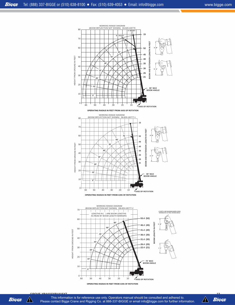
WORKING RANGE DIAGRAM(BOOM DEFLECTION NOT SHOWN) D6-829-100777-1
HE
IGH
T F
RO
M G
RO
UN
D IN
FE
ET
AXIS OF ROTATION
80° MAXBOOM ANGLE
BO
OM
AN
D E
XT
EN
SIO
N L
EN
GT
H IN
FE
ET
0°
10°
20°
30°
40°
50°
60°
70°
15
52
45
40
35
30
25
21
OPERATING RADIUS IN FEET FROM AXIS OF ROTATION
3' -8"
3' -4"
HE
IGH
T F
RO
M G
RO
UN
D IN
FE
ET
AXIS OF ROTATION
70° MAXBOOM ANGLE
BO
OM
LE
NG
TH
IN F
EE
T
OPERATING RADIUS IN FEET FROM AXIS OF ROTATION
70
60
50
40
30
20
10
060 50 40 30 20 10
LENGTHS IN ( ) ARE BOOM LENGTHSAS READ BY BOOM LENGTH MARKERS
WORKING RANGE DIAGRAM(BOOM DEFLECTION NOT SHOWN) DB-829-100777-2
10°
20°
40°
50°
60°
30°
53.4 (52)
46.4 (45)
41.4 (40)
36.4 (35)
31.4 (30)
26.4 (25)22.4 (21)
0°
3' -6"
2 PARTS LINE MAXIMUM WHEN USINGHOOKBLOCK AT MAX. BOOM ANGLE
3' -2"
80
70
60
50
40
30
20
10
060 50 40 30 20 10
WORKING RANGE DIAGRAM(BOOM DEFLECTION NOT SHOWN) D6-829-100778
HE
IGH
T F
RO
M G
RO
UN
D IN
FE
ET
BO
OM
AN
D E
XT
EN
SIO
N L
EN
GT
H IN
FE
ET
80° MAXBOOM ANGLE
AXIS OF ROTATION
OPERATING RADIUS IN FEET FROM AXIS OF ROTATION
3' -8"
3' -4"
45° OFFSET
0° OFFSET
15
52
45
40
35
30
25
21
0°
10°
20°
30°
40°
50°
60°
70°
14 GROVE YB4415/YB4415XT
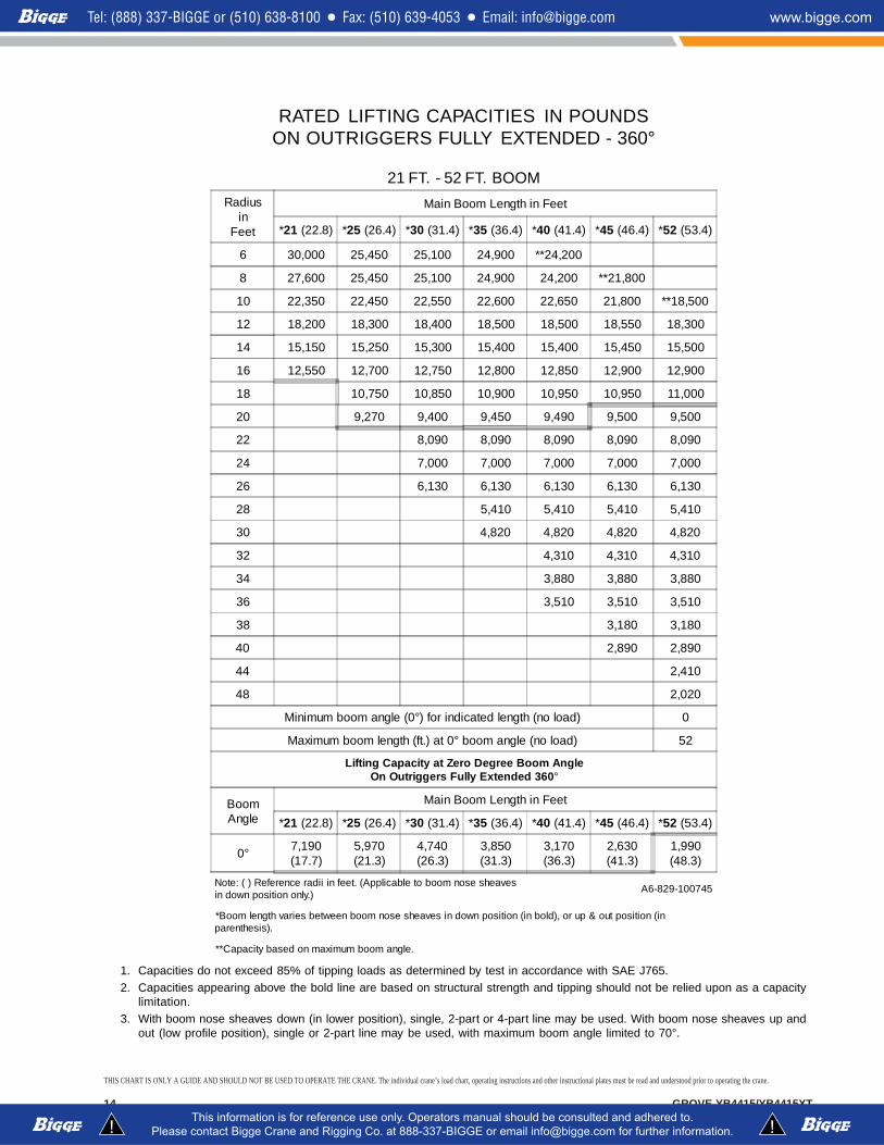
RATED LIFTING CAPACITIES IN POUNDSON OUTRIGGERS FULLY EXTENDED - 360°
21 FT. - 52 FT. BOOM
1. Capacities do not exceed 85% of tipping loads as determined by test in accordance with SAE J765.2. Capacities appearing above the bold line are based on structural strength and tipping should not be relied upon as a capacity
limitation.3. With boom nose sheaves down (in lower position), single, 2-part or 4-part line may be used. With boom nose sheaves up and
out (low profile position), single or 2-part line may be used, with maximum boom angle limited to 70°.
Radiusin
Feet
Main Boom Length in Feet
*21 (22.8) *25 (26.4) *30 (31.4) *35 (36.4) *40 (41.4) *45 (46.4) *52 (53.4)
6 30,000 25,450 25,100 24,900 **24,200
8 27,600 25,450 25,100 24,900 24,200 **21,800
10 22,350 22,450 22,550 22,600 22,650 21,800 **18,500
12 18,200 18,300 18,400 18,500 18,500 18,550 18,300
14 15,150 15,250 15,300 15,400 15,400 15,450 15,500
16 12,550 12,700 12,750 12,800 12,850 12,900 12,900
18 10,750 10,850 10,900 10,950 10,950 11,000
20 9,270 9,400 9,450 9,490 9,500 9,500
22 8,090 8,090 8,090 8,090 8,090
24 7,000 7,000 7,000 7,000 7,000
26 6,130 6,130 6,130 6,130 6,130
28 5,410 5,410 5,410 5,410
30 4,820 4,820 4,820 4,820
32 4,310 4,310 4,310
34 3,880 3,880 3,880
36 3,510 3,510 3,510
38 3,180 3,180
40 2,890 2,890
44 2,410
48 2,020
Minimum boom angle (0°) for indicated length (no load) 0
Maximum boom length (ft.) at 0° boom angle (no load) 52
Lifting Capacity at Zero Degree Boom AngleOn Outriggers Fully Extended 360°
BoomAngle
Main Boom Length in Feet
*21 (22.8) *25 (26.4) *30 (31.4) *35 (36.4) *40 (41.4) *45 (46.4) *52 (53.4)
0° 7,190(17.7)
5,970(21.3)
4,740(26.3)
3,850(31.3)
3,170(36.3)
2,630(41.3)
1,990(48.3)
Note: ( ) Reference radii in feet. (Applicable to boom nose sheavesin down position only.)
A6-829-100745
*Boom length varies between boom nose sheaves in down position (in bold), or up & out position (inparenthesis).
**Capacity based on maximum boom angle.
THIS CHART IS ONLY A GUIDE AND SHOULD NOT BE USED TO OPERATE THE CRANE. The individual crane’s load chart, operating instructions and other instructional plates must be read and understood prior to operating the crane.
GROVE YB4415/YB4415XT 15
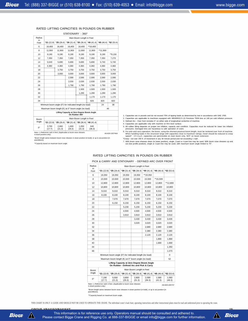
RATED LIFTING CAPACITIES IN POUNDS ON RUBBER
STATIONARY - 360°Radius
inFeet
Main Boom Length in Feet
*21 (22.8) *25 (26.4) *30 (31.4) *35 (36.4) *40 (41.4) *45 (46.4) *52 (53.4)
6 16,400 16,400 16,400 16,400 **16,400
8 11,900 11,900 11,900 11,900 11,900 **11,900
10 9,190 9,190 9,190 9,190 9,190 9,190 **9,150
12 7,350 7,350 7,350 7,350 7,350 7,350 7,270
14 5,540 5,690 5,690 5,690 5,690 5,740 5,740
16 4,360 4,360 4,360 4,360 4,360 4,360 4,360
18 3,750 3,750 3,750 3,750 3,750 3,750
20 3,000 3,000 3,000 3,000 3,000 3,000
22 2,590 2,590 2,590 2,590 2,590
24 2,030 2,030 2,030 2,030 2,030
26 1,790 1,790 1,790 1,790 1,790
28 1,500 1,500 1,500 1,500
30 1,290 1,290 1,290 1,290
32 1,170 1,170 1,170
34 820 820 820
Minimum boom angle (0°) for indicated length (no load) 24 38
Maximum boom length (ft.) at 0° boom angle (no load) 40
Lifting Capacity at Zero Degree Boom AngleOn Rubber 360°
BoomAngle
Main Boom Length in Feet
*21 (22.8) *25 (26.4) *30 (31.4) *35 (36.4) *40 (41.4)
0° 3,700(17.7)
2,660(21.3)
1,600(26.3)
1,050(31.3)
640(36.3)
Note: ( ) Reference radii in feet. (Applicable to boom nose sheavesin down position only.)
A6-829-100746A
*Boom length varies between boom nose sheaves in down position (in bold), or up & out position (inparenthesis).
**Capacity based on maximum boom angle.
1. Capacities are in pounds and do not exceed 75% of tipping loads as determined by test in accordance with SAE J765.2. Capacities are applicable to machines equipped with 385/65R22.5 (J) Firestone T839 tires at 140 psi cold inflation pressure.3. Defined Arc - Over front includes 6° on either side of longitudinal centerline of machine.4. Capacities are applicable only with machine on firm level surface.5. All rubber lifting depends on proper tire inflation, capacity and condition. Capacities must be reduced for lower tire inflation
pressures. Damaged tires are hazardous to safe operation of crane.6. For pick and carry operation, the boom, using the shortest practical boom length, must be centered over front of machine.
When handling loads in the structural range with capacities close to maximum ratings, travel should be reduced to creepspeed*. 2.5 m.p.h. capacities are permissible on main boom only, NOT on boom extension.
*Creep - not over 200 ft. of movement in any 30 minute period and not exceeding 1 mph.7. With boom nose sheaves down (in lower position), single, 2-part or 4-part line may be used. With boom nose sheaves up and
out (low profile position), single or 2-part line may be used, with maximum boom angle limited to 70°.
RATED LIFTING CAPACITIES IN POUNDS ON RUBBER
PICK & CARRY AND STATIONARY - DEFINED ARC OVER FRONT
Radiusin
Feet
Main Boom Length in Feet
*21 (22.8) *25 (26.4) *30 (31.4) *35 (36.4) *40 (41.4) *45 (46.4) *52 (53.4)
6 19,350 19,350 19,350 19,350 **19,350
8 15,500 15,500 15,500 15,500 15,500 **15,500
10 12,800 12,800 12,800 12,800 12,800 12,800 **12,800
12 10,800 10,800 10,800 10,800 10,800 10,800 10,800
14 9,310 9,310 9,310 9,310 9,310 9,310 9,310
16 8,100 8,100 8,100 8,100 8,100 8,100 8,100
18 7,070 7,070 7,070 7,070 7,070 7,070
20 6,150 6,150 6,150 6,150 6,150 6,150
22 5,230 5,230 5,230 5,230 5,230
24 4,500 4,500 4,500 4,500 4,500
26 3,910 3,910 3,910 3,910 3,910
28 3,430 3,430 3,430 3,430
30 3,020 3,020 3,020 3,020
32 2,680 2,680 2,680
34 2,380 2,380 2,380
36 2,120 2,120 2,120
38 1,890 1,890
40 1,690 1,690
44 1,350
48 1,070
Minimum boom angle (0°) for indicated length (no load) 0
Maximum boom length (ft.) at 0° boom angle (no load) 52
Lifting Capacity at Zero Degree Boom AngleOn Rubber - Defined Arc and Pick & Carry
BoomAngle
Main Boom Length in Feet
*21 (22.8) *25 (26.4) *30 (31.4) *35 (36.4) *40 (41.4) *45 (46.4) *52 (53.4)
0° 7,190(17.7)
5,550(21.3)
3,850(26.3)
2,800(31.3)
2,090(36.3)
1,580(41.3)
1,060(48.3)
Note: ( ) Reference radii in feet. (Applicable to boom nose sheavesin down position only.)
A6-829-100747
*Boom length varies between boom nose sheaves in down position (in bold), or up & out position (inparenthesis).
**Capacity based on maximum boom angle.
THIS CHART IS ONLY A GUIDE AND SHOULD NOT BE USED TO OPERATE THE CRANE. The individual crane’s load chart, operating instructions and other instructional plates must be read and understood prior to operating the crane.
16 GROVE YB4415/YB4415XT
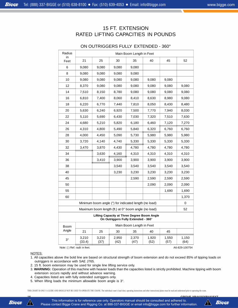
15 FT. EXTENSIONRATED LIFTING CAPACITIES IN POUNDS
ON OUTRIGGERS FULLY EXTENDED - 360°
NOTES:1. All capacities above the bold line are based on structural strength of boom extension and do not exceed 85% of tipping loads on
outriggers in accordance with SAE J765.2. 15 ft. boom extension may be used for single line lifting service only.3. WARNING: Operation of this machine with heavier loads than the capacities listed is strictly prohibited. Machine tipping with boom
extension occurs rapidly and without advance warning.4. Capacities listed are with fully extended outriggers only.5. When lifting loads the minimum allowable boom angle is 3°.
Radiusin
Feet
Main Boom Length in Feet
21 25 30 35 40 45 52
6 9,080 9,080 9,080 9,080
8 9,080 9,080 9,080 9,080
10 9,080 9,080 9,080 9,080 9,080 9,080
12 8,370 9,080 9,080 9,080 9,080 9,080 9,080
14 7,510 8,150 8,780 9,080 9,080 9,080 9,080
16 6,810 7,400 8,060 8,410 8,630 8,980 9,080
18 6,220 6,770 7,440 7,810 8,050 8,430 8,480
20 5,630 6,240 6,920 7,500 7,770 7,940 8,030
22 5,110 5,690 6,430 7,030 7,320 7,510 7,630
24 4,680 5,210 5,820 6,180 6,460 7,120 7,270
26 4,310 4,800 5,490 5,840 6,320 6,760 6,760
28 4,000 4,450 5,090 5,730 5,980 5,980 5,980
30 3,720 4,140 4,740 5,330 5,330 5,330 5,330
32 3,470 3,870 4,430 4,780 4,780 4,780 4,780
34 3,630 4,160 4,310 4,310 4,310 4,310
36 3,410 3,900 3,900 3,900 3,900 3,900
38 3,540 3,540 3,540 3,540 3,540
40 3,230 3,230 3,230 3,230 3,230
45 2,590 2,590 2,590 2,590
50 2,090 2,090 2,090
55 1,690 1,690
60 1,370
Minimum boom angle (°) for indicated length (no load) 0
Maximum boom length (ft.) at 0° boom angle (no load) 52
Lifting Capacity at Three Degree Boom AngleOn Outriggers Fully Extended - 360°
BoomAngle
Main Boom Length in Feet
21 25 30 35 40 45
3° 3,210(33.4)
3,210(37)
2,950(42)
2,370(47)
1,920(52)
1,550(57)
1,150(64)
Note: ( ) Ref. radii in feet. A6-829-100754
THIS CHART IS ONLY A GUIDE AND SHOULD NOT BE USED TO OPERATE THE CRANE. The individual crane’s load chart, operating instructions and other instructional plates must be read and understood prior to operating the crane.
GROVE YB4415/YB4415XT 17
15 FT. EXTENSIONRATED LIFTING CAPACITIES IN POUNDS ON RUBBER
STATIONARY 360°Radius
inFeet
Main Boom Length in Feet
21 25 30 35 40 45 52
6 9,080 9,080 **9,080
8 9,080 9,080 9,080 **9,080
10 9,080 9,080 9,080 9,080 9,080
12 7,970 7,970 7,970 7,910 7,860 7,860
14 6,600 6,600 6,480 6,480 6,330 6,330 6,220
16 5,480 5,380 5,330 5,280 5,280 5,230 5,180
18 4,670 4,550 4,520 4,520 4,520 4,340 4,340
20 3,950 3,830 3,700 3,700 3,650 3,650 3,600
22 3,370 3,270 3,210 3,210 3,110 3,110 3,110
24 2,880 2,850 2,750 2,700 2,600 2,550 2,450
26 2,510 2,410 2,360 2,250 2,200 2,200 2,150
28 2,160 2,160 2,040 1,940 1,890 1,890 1,790
30 1,890 1,840 1,740 1,690 1,580 1,580 1,580
32 1,640 1,580 1,430 1,430 1,370 1,370 1,370
34 1,370 1,300 1,220 1,170 1,120 1,120
36 1,230 1,120 1,070 970 920 920
Minimum boom angle (°) for indicated length(no load) 31 38 44 50
Maximum boom length (ft.) at 0° boom angle(no load) 30
Lifting Capacity at Three Degree Boom AngleOn Rubber Stationary - 360°
BoomAngle
Main Boom Length in Feet
21 25
3° 1,510(33.4)
1,130(37)
Note: ( ) Ref. radii in feet..**This capacity based on maximum boom angle. A6-829-100755A
NOTES:1. All capacities above the bold line are based on structural strength of boom extension and do not exceed 75% of tipping
loads on rubber in accordance with SAE J765.2. 15 ft. boom extension may be used for single line lifting service only.3. Defined Arc - Over front includes 6° on either side of longitudinal centerline of machine. Pick and carry lifting NOT
permitted.4. Capacities are applicable to machines equipped with 385/65R22.5 (J) Firestone T839 tires at 140 psi cold inflation pressure.5. Capacities are applicable only with machine on firm level surface.6. All rubber lifting depends on proper tire inflation, capacity and condition. Capacities must be reduced for lower tire inflation
pressures. Damaged tires are hazardous to safe operation of crane.7. WARNING: Operation of this machine with heavier loads than the capacities listed is strictly prohibited. Machine tipping
with boom extension occurs rapidly and without advance warning.8. When lifting loads the minimum allowable boom angle is 3°.
15 FT. EXTENSIONRATED LIFTING CAPACITIES IN POUNDS ON RUBBER
STATIONARY - DEFINED ARC OVER FRONT
Radiusin
Feet
Main Boom Length in Feet
21 25 30 35 40 45 52
6 9,080 9,080 9,080 **9,080
8 9,080 9,080 9,080 9,080
10 9,080 9,080 9,080 9,080 9,080 **9,080
12 8,370 9,080 9,080 9,080 9,080 9,080 **9,080
14 7,510 8,150 8,780 9,080 9,080 9,080 9,080
16 6,810 7,400 8,060 8,410 8,600 8,600 8,600
18 6,220 6,770 7,440 7,600 7,600 7,600 7,600
20 5,630 6,240 6,760 6,760 6,760 6,760 6,760
22 5,110 5,690 5,910 5,910 5,910 5,910 5,910
24 4,680 5,110 5,110 5,110 5,110 5,110 5,110
26 4,310 4,450 4,450 4,450 4,450 4,450 4,450
28 3,920 3,920 3,920 3,920 3,920 3,920 3,920
30 3,470 3,470 3,470 3,470 3,470 3,470 3,470
32 3,080 3,080 3,080 3,080 3,080 3,080 3,080
34 2,750 2,750 2,750 2,750 2,750 2,750
36 2,460 2,460 2,460 2,460 2,460 2,460
38 2,210 2,210 2,210 2,210 2,210
40 1,990 1,990 1,990 1,990 1,990
45 1,530 1,530 1,530 1,530
50 1,170 1,170 1,170
55 880 880
Minimum boom angle (°) for indicated length (no load) 0
Maximum boom length (ft.) at 0° boom angle (no load) 52
Lifting Capacity at Three Degree Boom AngleOn Rubber - Defined Arc Over Front
BoomAngle
Main Boom Length in Feet
21 25 30 35 40 45
3° 2,850(33.4)
2,330(37)
1,790(42)
1,370(47)
1,050(52)
780(57)
**This capacity is based upon maximum boom angle.Note: ( ) Ref. radii in feet.
A6-829-100756
NOTES:1. All capacities above the bold line are based on structural strength of boom extension and do not exceed 75% of tipping loads on
rubber in accordance with SAE J765.2. 15 ft. boom extension may be used for single line lifting service only.3. Defined Arc - Over front includes 6° on either side of longitudinal centerline of machine. Pick and carry lifting NOT permitted.4. Capacities are applicable to machines equipped with 385/65R22.5 (J) Firestone T839 tires at 140 psi cold inflation pressure.5. Capacities are applicable only with machine on firm level surface.6. All rubber lifting depends on proper tire inflation, capacity and condition. Capacities must be reduced for lower tire inflation
pressures. Damaged tires are hazardous to safe operation of crane.7. WARNING: Operation of this machine with heavier loads than the capacities listed is strictly prohibited. Machine tipping with boom
extension occurs rapidly and without advance warning.8. When lifting loads the minimum allowable boom angle is 3°.
THIS CHART IS ONLY A GUIDE AND SHOULD NOT BE USED TO OPERATE THE CRANE. The individual crane’s load chart, operating instructions and other instructional plates must be read and understood prior to operating the crane.
18 GROVE YB4415/YB4415XT
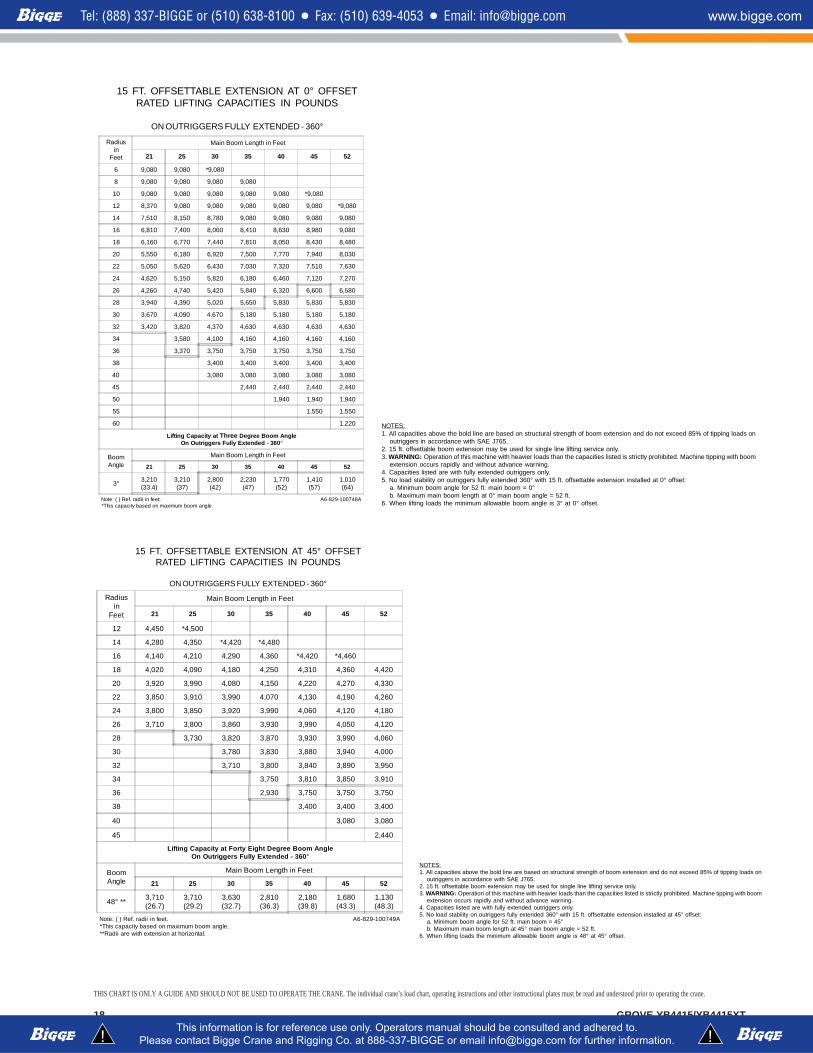
15 FT. OFFSETTABLE EXTENSION AT 0° OFFSETRATED LIFTING CAPACITIES IN POUNDS
ON OUTRIGGERS FULLY EXTENDED - 360°
Radiusin
Feet
Main Boom Length in Feet
21 25 30 35 40 45 52
6 9,080 9,080 *9,080
8 9,080 9,080 9,080 9,080
10 9,080 9,080 9,080 9,080 9,080 *9,080
12 8,370 9,080 9,080 9,080 9,080 9,080 *9,080
14 7,510 8,150 8,780 9,080 9,080 9,080 9,080
16 6,810 7,400 8,060 8,410 8,630 8,980 9,080
18 6,160 6,770 7,440 7,810 8,050 8,430 8,480
20 5,550 6,180 6,920 7,500 7,770 7,940 8,030
22 5,050 5,620 6,430 7,030 7,320 7,510 7,630
24 4,620 5,150 5,820 6,180 6,460 7,120 7,270
26 4,260 4,740 5,420 5,840 6,320 6,600 6,580
28 3,940 4,390 5,020 5,650 5,830 5,830 5,830
30 3,670 4,090 4,670 5,180 5,180 5,180 5,180
32 3,420 3,820 4,370 4,630 4,630 4,630 4,630
34 3,580 4,100 4,160 4,160 4,160 4,160
36 3,370 3,750 3,750 3,750 3,750 3,750
38 3,400 3,400 3,400 3,400 3,400
40 3,080 3,080 3,080 3,080 3,080
45 2,440 2,440 2,440 2,440
50 1,940 1,940 1,940
55 1,550 1,550
60 1,220
Lifting Capacity at Three Degree Boom AngleOn Outriggers Fully Extended - 360°
BoomAngle
Main Boom Length in Feet
21 25 30 35 40 45 52
3° 3,210(33.4)
3,210(37)
2,800(42)
2,230(47)
1,770(52)
1,410(57)
1,010(64)
Note: ( ) Ref. radii in feet.*This capacity based on maximum boom angle.
A6-829-100748A
NOTES:1. All capacities above the bold line are based on structural strength of boom extension and do not exceed 85% of tipping loads on
outriggers in accordance with SAE J765.2. 15 ft. offsettable boom extension may be used for single line lifting service only.3. WARNING: Operation of this machine with heavier loads than the capacities listed is strictly prohibited. Machine tipping with boom
extension occurs rapidly and without advance warning.4. Capacities listed are with fully extended outriggers only.5. No load stability on outriggers fully extended 360° with 15 ft. offsettable extension installed at 0° offset:
a. Minimum boom angle for 52 ft. main boom = 0°b. Maximum main boom length at 0° main boom angle = 52 ft.
6. When lifting loads the minimum allowable boom angle is 3° at 0° offset.
15 FT. OFFSETTABLE EXTENSION AT 45° OFFSETRATED LIFTING CAPACITIES IN POUNDS
ON OUTRIGGERS FULLY EXTENDED - 360°
Radiusin
Feet
Main Boom Length in Feet
21 25 30 35 40 45 52
12 4,450 *4,500
14 4,280 4,350 *4,420 *4,480
16 4,140 4,210 4,290 4,360 *4,420 *4,460
18 4,020 4,090 4,180 4,250 4,310 4,360 4,420
20 3,920 3,990 4,080 4,150 4,220 4,270 4,330
22 3,850 3,910 3,990 4,070 4,130 4,190 4,260
24 3,800 3,850 3,920 3,990 4,060 4,120 4,180
26 3,710 3,800 3,860 3,930 3,990 4,050 4,120
28 3,730 3,820 3,870 3,930 3,990 4,060
30 3,780 3,830 3,880 3,940 4,000
32 3,710 3,800 3,840 3,890 3,950
34 3,750 3,810 3,850 3,910
36 2,930 3,750 3,750 3,750
38 3,400 3,400 3,400
40 3,080 3,080
45 2,440
Lifting Capacity at Forty Eight Degree Boom AngleOn Outriggers Fully Extended - 360°
BoomAngle
Main Boom Length in Feet
21 25 30 35 40 45 52
48° ** 3,710(26.7)
3,710(29.2)
3,630(32.7)
2,810(36.3)
2,180(39.8)
1,680(43.3)
1,130(48.3)
Note: ( ) Ref. radii in feet.*This capacity based on maximum boom angle.**Radii are with extension at horizontal.
A6-829-100749A
NOTES:1. All capacities above the bold line are based on structural strength of boom extension and do not exceed 85% of tipping loads on
outriggers in accordance with SAE J765.2. 15 ft. offsettable boom extension may be used for single line lifting service only.3. WARNING: Operation of this machine with heavier loads than the capacities listed is strictly prohibited. Machine tipping with boom
extension occurs rapidly and without advance warning.4. Capacities listed are with fully extended outriggers only.5. No load stability on outriggers fully extended 360° with 15 ft. offsettable extension installed at 45° offset:
a. Minimum boom angle for 52 ft. main boom = 45°b. Maximum main boom length at 45° main boom angle = 52 ft.
6. When lifting loads the minimum allowable boom angle is 48° at 45° offset.
THIS CHART IS ONLY A GUIDE AND SHOULD NOT BE USED TO OPERATE THE CRANE. The individual crane’s load chart, operating instructions and other instructional plates must be read and understood prior to operating the crane.
GROVE YB4415/YB4415XT 19
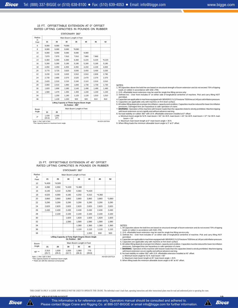
15 FT. OFFSETTABLE EXTENSION AT 0° OFFSETRATED LIFTING CAPACITIES IN POUNDS ON RUBBER
STATIONARY 360°Radius
inFeet
Main Boom Length in Feet
21 25 30 35 40 45 52
6 9,080 9,080 *9,080
8 9,080 9,080 9,080 *9,080
10 9,080 9,080 9,080 9,080 9,080
12 7,970 7,970 7,910 7,910 7,860 7,860
14 6,360 6,360 6,360 6,360 6,220 6,220 *6,220
16 5,280 5,280 5,180 5,180 5,180 5,180 5,180
18 4,350 4,350 4,350 4,350 4,150 4,100 4,000
20 3,770 3,720 3,620 3,500 3,450 3,450 3,330
22 3,230 3,130 3,020 2,910 2,910 2,830 2,780
24 2,730 2,680 2,570 2,520 2,470 2,370 2,370
26 2,420 2,310 2,210 2,160 2,110 2,010 2,010
28 2,060 2,010 1,960 1,840 1,730 1,730 1,730
30 1,820 1,690 1,590 1,540 1,490 1,490 1,490
32 1,580 1,470 1,350 1,300 1,240 1,240 1,240
34 1,250 1,190 1,120 1,120 1,010 1,010
36 1,100 1,040 920 920 810 810
Lifting Capacity at Three Degree Boom AngleOn Rubber - 360°
BoomAngle
Main Boom Length in Feet
21 25
3° 1,430(33.4)
1,090(37)
Note: ( ) Ref. radii in feet.*This capacity based on maximum boom angle.
A6-829-100750A
NOTES:1. All capacities above the bold line are based on structural strength of boom extension and do not exceed 75% of tipping
loads on rubber in accordance with SAE J765.2. 15 ft. offsettable boom extension may be used for single line lifting service only.3. Defined Arc - Over front includes 6° on either side of longitudinal centerline of machine. Pick and carry lifting NOT
permitted.4. Capacities are applicable to machines equipped with 385/65R22.5 (J) Firestone T839 tires at 140 psi cold inflation pressure.5. Capacities are applicable only with machine on firm level surface.6. All rubber lifting depends on proper tire inflation, capacity and condition. Capacities must be reduced for lower tire inflation
pressures. Damaged tires are hazardous to safe operation of crane.7. WARNING: Operation of this machine with heavier loads than the capacities listed is strictly prohibited. Machine tipping
with boom extension occurs rapidly and without advance warning.8. No load stability on rubber 360° with 15 ft. offsettable extension installed at 0° offset:
a. Minimum boom angle for 52 ft. main boom = 50°; for 45 ft. main boom = 43°; for 40 ft. main boom = 37°; for 35 ft. mainboom = 29°
b. Maximum main boom length at 0° main boom angle = 30 ft.9. When lifting loads the minimum allowable boom angle is 3° at 0° offset.
15 FT. OFFSETTABLE EXTENSION AT 45° OFFSETRATED LIFTING CAPACITIES IN POUNDS ON RUBBER
STATIONARY 360°
Radiusin
Feet
Main Boom Length in Feet
21 25 30 35 40 45 52
12 *4,450 *4,500
14 4,280 4,350 *4,420 *4,480
16 4,140 4,210 4,290 4,360 *4,420
18 4,020 4,090 4,180 4,250 4,310 *4,360
20 3,860 3,860 3,860 3,860 3,860 3,860 *3,860
22 3,290 3,290 3,290 3,290 3,290 3,290 3,290
24 2,820 2,820 2,820 2,820 2,820 2,820 2,820
26 2,430 2,430 2,430 2,430 2,430 2,430 2,430
28 2,100 2,100 2,100 2,100 2,100 2,100
30 1,820 1,820 1,820 1,820 1,820
32 1,580 1,580 1,580 1,580 1,580
34 1,360 1,360 1,360 1,360
36 1,110 1,110 1,110 1,110
38 1,000 930 930
Lifting Capacity at Forty Eight Degree Boom AngleOn Rubber - 360°
BoomAngle
Main Boom Length in Feet
21 25 30 35 40
48° ** 2,310(26.7)
1,930(29.2)
1,500(32.7)
1,060(36.3)
770(39.8)
Note: ( ) Ref. radii in feet.*This capacity based on maximum boom angle.** Radii are with the extension at horizontal.
A6-829-100751A
NOTES:1. All capacities above the bold line are based on structural strength of boom extension and do not exceed 75% of tipping
loads on rubber in accordance with SAE J765.2. 15 ft. offsettable boom extension may be used for single line lifting service only.3. Defined Arc - Over front includes 6° on either side of longitudinal centerline of machine. Pick and carry lifting NOT
permitted.4. Capacities are applicable to machines equipped with 385/65R22.5 (J) Firestone T839 tires at 140 psi cold inflation pressure.5. Capacities are applicable only with machine on firm level surface.6. All rubber lifting depends on proper tire inflation, capacity and condition. Capacities must be reduced for lower tire inflation
pressures. Damaged tires are hazardous to safe operation of crane.7. WARNING: Operation of this machine with heavier loads than the capacities listed is strictly prohibited. Machine tipping
with boom extension occurs rapidly and without advance warning.8. No load stability on rubber 360° with 15 ft. offsettable extension installed at 45° offset:
a. Minimum boom angle for 52 ft. main boom = 56°b. Maximum main boom length at 45° main boom angle = 45 ft.
9. When lifting loads the minimum allowable boom angle is 48° at 45° offset.
THIS CHART IS ONLY A GUIDE AND SHOULD NOT BE USED TO OPERATE THE CRANE. The individual crane’s load chart, operating instructions and other instructional plates must be read and understood prior to operating the crane.
20 GROVE YB4415/YB4415XT
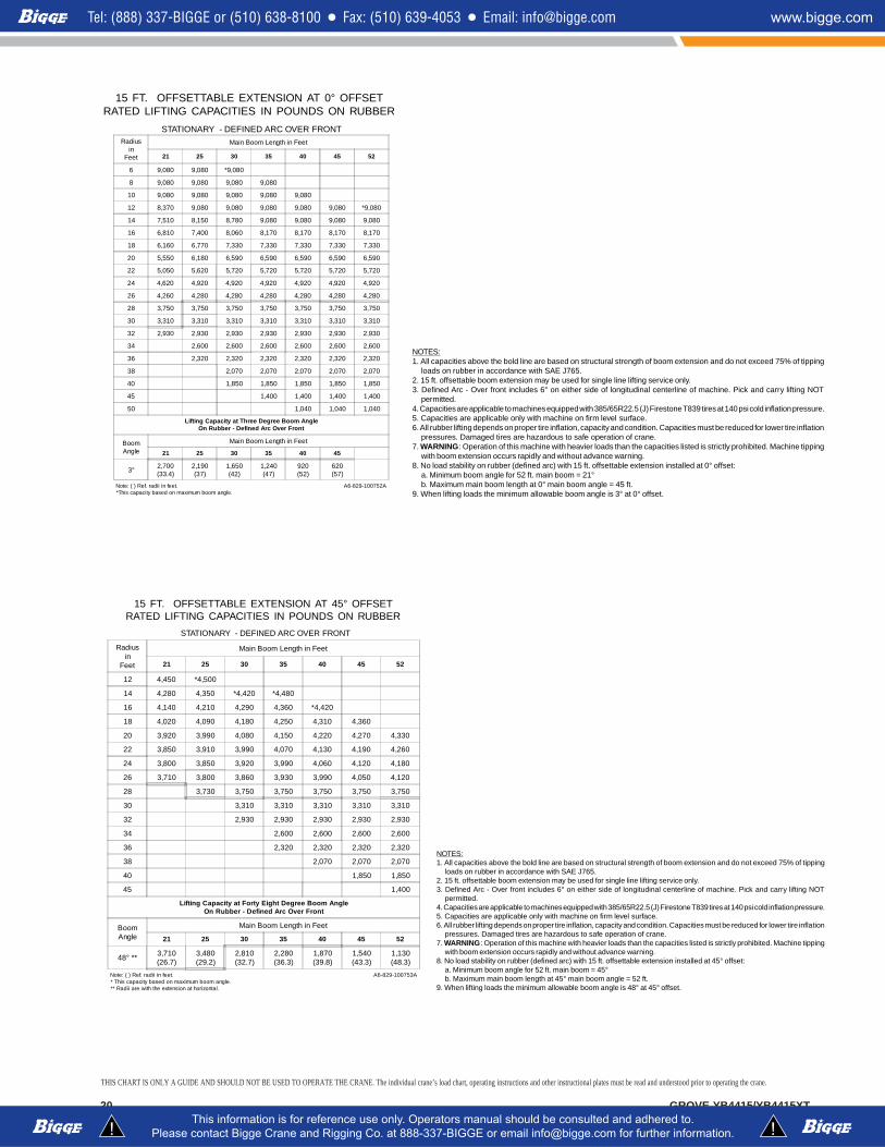
15 FT. OFFSETTABLE EXTENSION AT 0° OFFSETRATED LIFTING CAPACITIES IN POUNDS ON RUBBER
STATIONARY - DEFINED ARC OVER FRONTRadius
inFeet
Main Boom Length in Feet
21 25 30 35 40 45 52
6 9,080 9,080 *9,080
8 9,080 9,080 9,080 9,080
10 9,080 9,080 9,080 9,080 9,080
12 8,370 9,080 9,080 9,080 9,080 9,080 *9,080
14 7,510 8,150 8,780 9,080 9,080 9,080 9,080
16 6,810 7,400 8,060 8,170 8,170 8,170 8,170
18 6,160 6,770 7,330 7,330 7,330 7,330 7,330
20 5,550 6,180 6,590 6,590 6,590 6,590 6,590
22 5,050 5,620 5,720 5,720 5,720 5,720 5,720
24 4,620 4,920 4,920 4,920 4,920 4,920 4,920
26 4,260 4,280 4,280 4,280 4,280 4,280 4,280
28 3,750 3,750 3,750 3,750 3,750 3,750 3,750
30 3,310 3,310 3,310 3,310 3,310 3,310 3,310
32 2,930 2,930 2,930 2,930 2,930 2,930 2,930
34 2,600 2,600 2,600 2,600 2,600 2,600
36 2,320 2,320 2,320 2,320 2,320 2,320
38 2,070 2,070 2,070 2,070 2,070
40 1,850 1,850 1,850 1,850 1,850
45 1,400 1,400 1,400 1,400
50 1,040 1,040 1,040
Lifting Capacity at Three Degree Boom AngleOn Rubber - Defined Arc Over Front
BoomAngle
Main Boom Length in Feet
21 25 30 35 40 45
3° 2,700(33.4)
2,190(37)
1,650(42)
1,240(47)
920(52)
620(57)
Note: ( ) Ref. radii in feet.*This capacity based on maximum boom angle.
A6-829-100752A
NOTES:1. All capacities above the bold line are based on structural strength of boom extension and do not exceed 75% of tipping
loads on rubber in accordance with SAE J765.2. 15 ft. offsettable boom extension may be used for single line lifting service only.3. Defined Arc - Over front includes 6° on either side of longitudinal centerline of machine. Pick and carry lifting NOT
permitted.4. Capacities are applicable to machines equipped with 385/65R22.5 (J) Firestone T839 tires at 140 psi cold inflation pressure.5. Capacities are applicable only with machine on firm level surface.6. All rubber lifting depends on proper tire inflation, capacity and condition. Capacities must be reduced for lower tire inflation
pressures. Damaged tires are hazardous to safe operation of crane.7. WARNING: Operation of this machine with heavier loads than the capacities listed is strictly prohibited. Machine tipping
with boom extension occurs rapidly and without advance warning.8. No load stability on rubber (defined arc) with 15 ft. offsettable extension installed at 0° offset:
a. Minimum boom angle for 52 ft. main boom = 21°b. Maximum main boom length at 0° main boom angle = 45 ft.
9. When lifting loads the minimum allowable boom angle is 3° at 0° offset.
15 FT. OFFSETTABLE EXTENSION AT 45° OFFSETRATED LIFTING CAPACITIES IN POUNDS ON RUBBER
STATIONARY - DEFINED ARC OVER FRONT
Radiusin
Feet
Main Boom Length in Feet
21 25 30 35 40 45 52
12 4,450 *4,500
14 4,280 4,350 *4,420 *4,480
16 4,140 4,210 4,290 4,360 *4,420
18 4,020 4,090 4,180 4,250 4,310 4,360
20 3,920 3,990 4,080 4,150 4,220 4,270 4,330
22 3,850 3,910 3,990 4,070 4,130 4,190 4,260
24 3,800 3,850 3,920 3,990 4,060 4,120 4,180
26 3,710 3,800 3,860 3,930 3,990 4,050 4,120
28 3,730 3,750 3,750 3,750 3,750 3,750
30 3,310 3,310 3,310 3,310 3,310
32 2,930 2,930 2,930 2,930 2,930
34 2,600 2,600 2,600 2,600
36 2,320 2,320 2,320 2,320
38 2,070 2,070 2,070
40 1,850 1,850
45 1,400
Lifting Capacity at Forty Eight Degree Boom AngleOn Rubber - Defined Arc Over Front
BoomAngle
Main Boom Length in Feet
21 25 30 35 40 45 52
48° ** 3,710(26.7)
3,480(29.2)
2,810(32.7)
2,280(36.3)
1,870(39.8)
1,540(43.3)
1,130(48.3)
Note: ( ) Ref. radii in feet.* This capacity based on maximum boom angle.** Radii are with the extension at horizontal.
A6-829-100753A
NOTES:1. All capacities above the bold line are based on structural strength of boom extension and do not exceed 75% of tipping
loads on rubber in accordance with SAE J765.2. 15 ft. offsettable boom extension may be used for single line lifting service only.3. Defined Arc - Over front includes 6° on either side of longitudinal centerline of machine. Pick and carry lifting NOT
permitted.4. Capacities are applicable to machines equipped with 385/65R22.5 (J) Firestone T839 tires at 140 psi cold inflation pressure.5. Capacities are applicable only with machine on firm level surface.6. All rubber lifting depends on proper tire inflation, capacity and condition. Capacities must be reduced for lower tire inflation
pressures. Damaged tires are hazardous to safe operation of crane.7. WARNING: Operation of this machine with heavier loads than the capacities listed is strictly prohibited. Machine tipping
with boom extension occurs rapidly and without advance warning.8. No load stability on rubber (defined arc) with 15 ft. offsettable extension installed at 45° offset:
a. Minimum boom angle for 52 ft. main boom = 45°b. Maximum main boom length at 45° main boom angle = 52 ft.
9. When lifting loads the minimum allowable boom angle is 48° at 45° offset.
THIS CHART IS ONLY A GUIDE AND SHOULD NOT BE USED TO OPERATE THE CRANE. The individual crane’s load chart, operating instructions and other instructional plates must be read and understood prior to operating the crane.
GROVE YB4415/YB4415XT 21
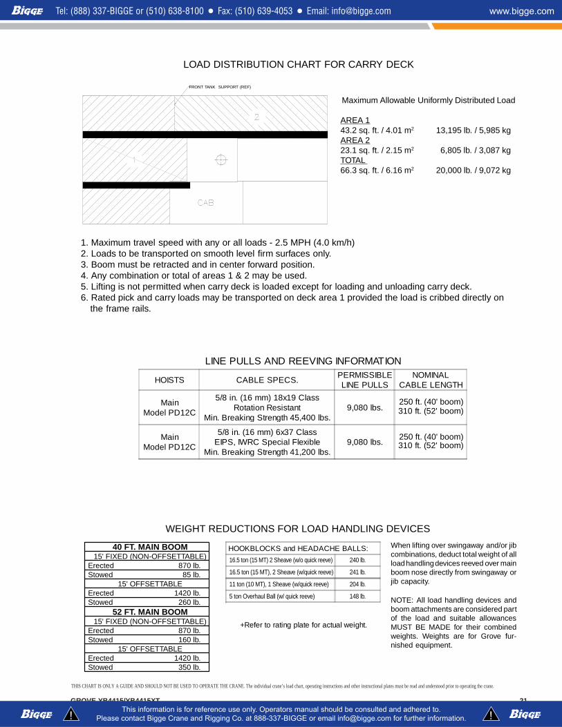
LOAD DISTRIBUTION CHART FOR CARRY DECK
WEIGHT REDUCTIONS FOR LOAD HANDLING DEVICES
When lifting over swingaway and/or jibcombinations, deduct total weight of allload handling devices reeved over mainboom nose directly from swingaway orjib capacity.
NOTE: All load handling devices andboom attachments are considered partof the load and suitable allowancesMUST BE MADE for their combinedweights. Weights are for Grove fur-nished equipment.
LINE PULLS AND REEVING INFORMATION
HOISTS CABLE SPECS.PERMISSIBLELINE PULLS
NOMINALCABLE LENGTH
MainModel PD12C
5/8 in. (16 mm) 18x19 ClassRotation Resistant
Min. Breaking Strength 45,400 lbs.9,080 lbs. 310 ft. (52' boom)
MainModel PD12C
5/8 in. (16 mm) 6x37 ClassEIPS, IWRC Special Flexible
Min. Breaking Strength 41,200 lbs.9,080 lbs. 310 ft. (52 ' boom)
HOOKBLOCKS and HEADACHE BALLS:
+Refer to rating plate for actual weight.
1. Maximum travel speed with any or all loads - 2.5 MPH (4.0 km/h)2. Loads to be transported on smooth level firm surfaces only.3. Boom must be retracted and in center forward position.4. Any combination or total of areas 1 & 2 may be used.5. Lifting is not permitted when carry deck is loaded except for loading and unloading carry deck.6. Rated pick and carry loads may be transported on deck area 1 provided the load is cribbed directly on
the frame rails.
Maximum Allowable Uniformly Distributed Load
AREA 143.2 sq. ft. / 4.01 m2 13,195 lb. / 5,985 kgAREA 223.1 sq. ft. / 2.15 m2 6,805 lb. / 3,087 kgTOTAL66.3 sq. ft. / 6.16 m2 20,000 lb. / 9,072 kg
FRONT TANK SUPPORT (REF)
16.5 ton (15 MT) 2 Sheave (w/o quick reeve) 240 lb.
16.5 ton (15 MT), 2 Sheave (w/quick reeve) 241 lb.
11 ton (10 MT), 1 Sheave (w/quick reeve) 204 lb.
5 ton Overhaul Ball (w/ quick reeve) 148 lb.
250 ft. (40' boom)
250 ft. (40' boom)
40 FT. MAIN BOOM15' FIXED (NON-OFFSETTABLE)
Erected 870 lb.Stowed 85 lb.
15' OFFSETTABLEErected 1420 lb.Stowed 260 lb.
52 FT. MAIN BOOM15' FIXED (NON-OFFSETTABLE)
Erected 870 lb.Stowed 160 lb.
15' OFFSETTABLEErected 1420 lb.Stowed 350 lb.
THIS CHART IS ONLY A GUIDE AND SHOULD NOT BE USED TO OPERATE THE CRANE. The individual crane’s load chart, operating instructions and other instructional plates must be read and understood prior to operating the crane.
Grove Worldwide - WorldHeadquartersWestern Hemisphere, Asia/Pacific1565 Buchanan Trail East P.O. Box 21 Shady Grove, Pennsylvania 17256-0021,USATel: [Int + 1] (717) 597-8121Fax: [Int + 1] (717) 597-4062
Grove Europe Limited*Europe, Africa, Middle East (Sales & Marketing)1 Emperor WayDoxford International Business ParkSunderland SR3 3XR, England Tel: [Int + 44] (191) 515-7253Fax: [Int + 44] (191) 564-0442
Grove Europe Limited*UK & EIRE (Sales & Service)Telford Road, Bicester Oxfordshire OX6 0TZ, England Tel: [Int + 44] (1869) 878-890Fax: [Int + 44] (1869) 878-891
Deutsche Grove GmbHGermany (Sales & Service)Helmholtzstrasse 12, Postfach 5026D-40750 Langenfeld, GermanyTel: [Int + 49] (2173) 8909-0Fax: [Int + 49] (2173) 8909-30
Deutsche Grove GmbH Wilhelmshaven WorksIndustriegelande West, Postfach 1853D-26358 Wilhelmshaven, Germany Tel: [Int + 49] (4421) 294-0Fax: [Int + 49] (4421) 294-301
Grove France SASFrance (Sales & Service)16, Chaussèe Jules-Cèsar, 95520OSNYB.P. 203, 95523 Cergy PontoiseFranceTel: [Int + 33] (1) 303-13150Fax: [Int + 33] (1) 303-86085
Grove Asia/Pacific - RepresentativeOffice Asia/Pacific, Near East171 Chin Swee Road#10-09 San Centre Singapore 16987Tel: [Int + 65] 536-6112 Fax: [Int + 65] 536-6119
Grove China - Representative OfficeRoom 713, Towercrest PlazaNo. 3 Mai Zi Dian West RoadChao Yang DistrictBeijing, China 100016Tel: [Int + 86] (10) 64 67 16 90Fax: [Int + 86] (10) 64 67 16 91
Grove Middle East P.O. Box 290Dubai, United Arab EmiratesTel: [Int + 971] (4) 3484478Fax: [Int + 971] (4) 3484478
Lifetime Customer SupportWestern Hemisphere, Asia/Pacific 1086 Wayne AvenueChambersburg, Pennsylvania 17201USATel: [Int + 1] (717) 263-5100Fax: [Int + 1] (717) 267-0404
Europe, Africa, Middle EastGrove Europe Limited*1 Emperor WayDoxford International Business ParkSunderland SR3 3XR, England Tel: [Int + 44] (191) 565-6281Parts Fax: [Int + 44] (191) 515-7475Service Fax: [Int + 44] (191) 515-7340
*Grove Europe Limited, Registered in England,Number 1845128.
Form No.: SBYB4415 Part No.: 3-1304 0800-4M Printed in U.S.A.
Constant improvement and engineering progress make it necessary that we reserve the right to makespecification, equipment, and price changes without notice. Illustrations shown may include optionalequipment and accessories and may not include all standard equipment.
http://www.groveworldwide.com
Distributed By:
GROVE® and GROVE LOGO are registered trademarks of GROVE in the U.S. and/or other countries.Copyright© 2000 GROVE. All rights reserved.