Embed Size (px)
Citation preview
81974_00_TOC.qxd 03/30/2005 05:40 PM Page ii
Licensed to:
81974_00_TOC.qxd 03/30/2005 05:40 PM Page ii
This is an electronic version of the print textbook. Due to electronic rights restrictions,some third party content may be suppressed. Editorial review has deemed that any suppressed content does not materially affect the overall learning experience. The publisher reserves the right to remove content from this title at any time if subsequent rights restrictions require it. Forvaluable information on pricing, previous editions, changes to current editions, and alternate formats, please visit www.cengage.com/highered to search by ISBN#, author, title, or keyword for materials in your areas of interest.
Copyright 2011 Cengage Learning. All Rights Reserved. May not be copied, scanned, or duplicated, in whole or in part. Due to electronic rights, some third party content may be suppressed from the eBook and/or eChapter(s).
Editorial review has deemed that any suppressed content does not materially affect the overall learning experience. Cengage Learning reserves the right to remove additional content at any time if subsequent rights restrictions require it.
Licensed to:

© 2006 Delmar, Cengage Learning
ALL RIGHTS RESERVED. No part of this work covered by the copyright herein may be reproduced, transmitted, stored or used in any form or by any means graphic, electronic, or mechanical, including but not limited to photocopying, recording, scanning, digitizing, taping, Web distribution, information networks, or information storage and retrieval systems, except as permitted under Section 107 or 108 of the 1976 United States Copyright Act, without the prior written permission of the publisher.
ISBN-13: 978-1-4018-6292-3
ISBN-10: 1-4018-6292-6
DelmarExecutive Woods5 Maxwell DriveClifton Park, NY 12065USA
Cengage Learning is a leading provider of customized learning solutions with offi ce locations around the globe, including Singapore, the United Kingdom, Australia, Mexico, Brazil, and Japan. Locate your local offi ce at international.cengage.com/region
Cengage Learning products are represented in Canada by Nelson Education, Ltd.
For your lifelong learning solutions, visit www.cengage.com/delmar
Visit our corporate website at www.cengage.com
Notice to the ReaderPublisher does not warrant or guarantee any of the products described herein or perform any independent analysis in connection with any of the product information contained herein. Publisher does not assume, and expressly disclaims, any obligation to obtain and include information other than that provided to it by the manufacturer. The reader is expressly warned to consider and adopt all safety precautions that might be indicated by the activities described herein and to avoid all potential hazards. By following the instructions contained herein, the reader willingly assumes all risks in connection with such instructions. The publisher makes no representations or warranties of any kind, including but not limited to, the warranties of fi tness for particular purpose or merchantability, nor are any such representations implied with respect to the material set forth herein, and the publisher takes no responsibility with respect to such material. The publisher shall not be liable for any special, consequential, or exemplary damages resulting, in whole or part, from the readers’ use of, or reliance upon, this material.
Industrial Control Electronics: Devices, Systems, and Applications, Third EditionTerry Bartelt
Vice President, Technology and Trades SBU: Alar Elken
Editorial Director: Sandy Clark
Senior Acquisitions Editor: Stephen Helba
Senior Development Editor: Michelle Ruelos Cannistraci
Marketing Director: Dave Garza
Senior Channel Manager: Dennis Williams
Marketing Coordinator: Stacey Wiktorek
Production Director: Mary Ellen Black
Senior Production Manager: Larry Main
Senior Project Editor: Christopher Chien
Art/Design Coordinator: Francis Hogan
Technology Project Manager: Kevin Smith
Technology Project Specialist: Linda Verde
Senior Editorial Assistant: Dawn Daugherty
For product information and technology assistance, contact us atCengage Learning Customer & Sales Support, 1-800-354-9706
For permission to use material from this text or product,submit all requests online at www.cengage.com/permissions
Further permissions questions can be emailed to [email protected]
Printed in the United States of America
5 6 7 11 10 09 08
Copyright 2011 Cengage Learning. All Rights Reserved. May not be copied, scanned, or duplicated, in whole or in part. Due to electronic rights, some third party content may be suppressed from the eBook and/or eChapter(s).
Editorial review has deemed that any suppressed content does not materially affect the overall learning experience. Cengage Learning reserves the right to remove additional content at any time if subsequent rights restrictions require it.
Licensed to:
S E C T I O N
1Industrial Control
Overview
OUTLINE
Chapter 1 Introduction to Industrial Control Systems
Chapter 2 Interfacing Devices
Chapter 3 Thyristors
Section one introduces key concepts in industrial control. The first chapter intro-duces the student to the ways in which industrial control systems are classified.It then provides an introductory overview of the elements that make up an in-
dustrial control loop.Chapter 2 describes the operation of discrete components and integrated circuits
that are used throughout the book.Chapter 3 covers thyristor devices and circuits that provide power to actuators
of a closed-loop system.The remaining sections describe each element of a control loop in detail so that
the entire spectrum of industrial control is addressed.
81974_01_ch01_pg001-016.qxd 03/31/2005 02:54 PM Page 1
Copyright 2011 Cengage Learning. All Rights Reserved. May not be copied, scanned, or duplicated, in whole or in part. Due to electronic rights, some third party content may be suppressed from the eBook and/or eChapter(s).
Editorial review has deemed that any suppressed content does not materially affect the overall learning experience. Cengage Learning reserves the right to remove additional content at any time if subsequent rights restrictions require it.
Licensed to:

81974_01_ch01_pg001-016.qxd 03/30/2005 06:58 PM Page 2
Copyright 2011 Cengage Learning. All Rights Reserved. May not be copied, scanned, or duplicated, in whole or in part. Due to electronic rights, some third party content may be suppressed from the eBook and/or eChapter(s).
Editorial review has deemed that any suppressed content does not materially affect the overall learning experience. Cengage Learning reserves the right to remove additional content at any time if subsequent rights restrictions require it.
Licensed to:
C H A P T E R
1Introduction toIndustrial ControlSystems
OBJECTIVES
At the conclusion of this chapter, you should be able to:
� List the classifications of industrial control systems.� Describe the differences between the different industrial control systems and provide
examples of each type.� Define the following terms associated with industrial control systems:
� Describe the differences between open-loop and closed-loop systems.� Define the following terms associated with open- and closed-loop systems:
� List the factors that affect the dynamic response of a closed-loop system.� Describe the operation of Feed-Forward Control.� List three factors that cause the controlled variable to differ from the set point.
INTRODUCTION
The industrial revolution began in England during the mid-1700s when it was discoveredthat productivity of spinning wheels and weaving machines could be dramatically increasedby fitting them with steam-powered engines. Further inventions and new ideas in plant lay-outs during the 1850s enabled the United States to surpass England as the manufacturingleader of the world. Around the turn of the twentieth century, the electric motor replacedsteam and water wheels as a power source. Factories became larger, machines were improvedto allow closer tolerances, and the assembly line method of mass production was created.
Between World Wars I and II, the feedback control system was developed, enablingmanually operated machines to be replaced by automated equipment. The feedback controlsystem is a key element in today’s manufacturing operations. The term industrial controlsis used to define this type of system, which automatically monitors manufacturing processes
Negative Feedback
Controlled Variable
Measurement Device
Feedback Signal
Set Point
Error Detector
Error Signal
Controller
Actuator
Manufacturing Process
Disturbance
Measured Variable
Manipulated Variable
Controller Output Signal
Servos
Servomechanisms
Batch
Continuous
Instrumentation
81974_01_ch01_pg001-016.qxd 03/30/2005 06:59 PM Page 3
Copyright 2011 Cengage Learning. All Rights Reserved. May not be copied, scanned, or duplicated, in whole or in part. Due to electronic rights, some third party content may be suppressed from the eBook and/or eChapter(s).
Editorial review has deemed that any suppressed content does not materially affect the overall learning experience. Cengage Learning reserves the right to remove additional content at any time if subsequent rights restrictions require it.
Licensed to:

being executed and takes appropriate corrective action if the operation is not performingproperly.
During World War II, significant advances in feedback technology occurred due to thesophisticated control systems required by military weapons. After the war, the techniquesused in military equipment were applied to industrial controls to further improve the qualityof products and to increase productivity.
Because many modern factory machines are automated, the technicians who install,troubleshoot, and repair them need to be highly trained. To perform effectively, these indi-viduals must understand the elements, operational theory, and terminology associated withindustrial control systems.
Industrial control theory encompasses many fields, but uses the same basic principleswhether controlling the position of an object, the speed of a motor, or the temperature andpressure of a manufacturing process.
In this chapter, the various types of industrial control systems, their characteristics, andimportant terminology will be studied.
1-1 Industrial Control ClassificationsMotion and Process ControlsIndustrial control systems are often classified by what they control: either motion or process.
Motion ControlA motion control system is an automatic control system that controls the physical motionor position of an object. One example is the industrial robot arm which performs weldingoperations and assembly procedures.
There are three characteristics that are common to all motion control systems. First,motion control devices control the position, speed, acceleration, or deceleration of amechanical object. Second, the motion or position of the object being controlled is mea-sured. Third, motion devices typically respond to input commands within fractions of asecond, rather than seconds or minutes, as in process control. Hence, motion control systemsare faster than process control systems.
Motion control systems are also referred to as servos, or servomechanisms. Other exam-ples of motion control applications are CNC machine tool equipment, printing presses,office copiers, packaging equipment, and electronics parts insertion machines that placecomponents onto a printed circuit board.
Process ControlThe other type of industrial control system is process control. In process control, one ormore variables are regulated during the manufacturing of a product. These variables may in-clude temperature, pressure, flow rate, liquid and solid level, pH, or humidity. This regulatedprocess must compensate for any outside disturbance that changes the variable. The responsetime of a process control system is typically slow, and can vary from a few seconds to sev-eral minutes. Process control is the type of industrial control system most often used in man-ufacturing. Process control systems are divided into two categories, batch and continuous.
Batch Process Batch processing is a sequence of timed operations executed on the prod-uct being manufactured. An example is an industrial machine that produces various types ofcookies, as shown in Figure 1-1. Suppose that chocolate-chip cookies are made in the firstproduction run. First, the oven is turned on to the desired temperature. Next, the requiredingredients in proper quantities are dispensed into the sealed mixing chamber. A largeblender then begins to mix the contents.
After a few minutes, vanilla is added, and the mixing process continues. After a pre-scribed period of time, the dough is the proper consistency, the blender stops turning, andthe compressor turns on to force air into the mixing chamber. When the air pressure reaches
4 SECTION 1 � Industrial Control Overview
81974_01_ch01_pg001-016.qxd 03/30/2005 01:58 PM Page 4
Copyright 2011 Cengage Learning. All Rights Reserved. May not be copied, scanned, or duplicated, in whole or in part. Due to electronic rights, some third party content may be suppressed from the eBook and/or eChapter(s).
Editorial review has deemed that any suppressed content does not materially affect the overall learning experience. Cengage Learning reserves the right to remove additional content at any time if subsequent rights restrictions require it.
Licensed to:
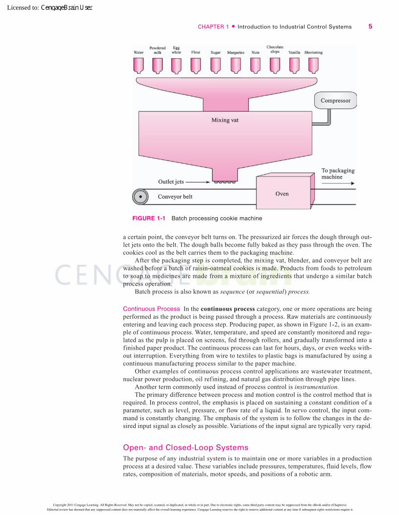
a certain point, the conveyor belt turns on. The pressurized air forces the dough through out-let jets onto the belt. The dough balls become fully baked as they pass through the oven. Thecookies cool as the belt carries them to the packaging machine.
After the packaging step is completed, the mixing vat, blender, and conveyor belt arewashed before a batch of raisin-oatmeal cookies is made. Products from foods to petroleumto soap to medicines are made from a mixture of ingredients that undergo a similar batchprocess operation.
Batch process is also known as sequence (or sequential) process.
Continuous Process In the continuous process category, one or more operations are beingperformed as the product is being passed through a process. Raw materials are continuouslyentering and leaving each process step. Producing paper, as shown in Figure 1-2, is an exam-ple of continuous process. Water, temperature, and speed are constantly monitored and regu-lated as the pulp is placed on screens, fed through rollers, and gradually transformed into afinished paper product. The continuous process can last for hours, days, or even weeks with-out interruption. Everything from wire to textiles to plastic bags is manufactured by using acontinuous manufacturing process similar to the paper machine.
Other examples of continuous process control applications are wastewater treatment,nuclear power production, oil refining, and natural gas distribution through pipe lines.
Another term commonly used instead of process control is instrumentation.The primary difference between process and motion control is the control method that is
required. In process control, the emphasis is placed on sustaining a constant condition of aparameter, such as level, pressure, or flow rate of a liquid. In servo control, the input com-mand is constantly changing. The emphasis of the system is to follow the changes in the de-sired input signal as closely as possible. Variations of the input signal are typically very rapid.
Open- and Closed-Loop SystemsThe purpose of any industrial system is to maintain one or more variables in a productionprocess at a desired value. These variables include pressures, temperatures, fluid levels, flowrates, composition of materials, motor speeds, and positions of a robotic arm.
CHAPTER 1 � Introduction to Industrial Control Systems 5
FIGURE 1-1 Batch processing cookie machine
81974_01_ch01_pg001-016.qxd 03/30/2005 01:58 PM Page 5
Copyright 2011 Cengage Learning. All Rights Reserved. May not be copied, scanned, or duplicated, in whole or in part. Due to electronic rights, some third party content may be suppressed from the eBook and/or eChapter(s).
Editorial review has deemed that any suppressed content does not materially affect the overall learning experience. Cengage Learning reserves the right to remove additional content at any time if subsequent rights restrictions require it.
Licensed to:

Industrial control systems are also classified by how they control variables, either manu-ally in an open-loop system or automatically in a closed-loop system.
Open-Loop SystemsAn open-loop system is the simplest way to control a system. A tank that supplies water foran irrigation system can be used to illustrate an open-loop (or manual control) system. Thediagram in Figure 1-3 shows a system composed of a storage tank, an inlet pipe with amanual control valve, and an outlet pipe. A continuous flow of water from a natural springenters the tank at the inlet, and water flows from the outlet pipe to the irrigation system. Theprocess variable that is maintained in the tank is the water level. Ideally, the manual flowcontrol valve setting and the size of the outlet pipe are exactly the same. When this occurs,the water level in the tank remains the same. Therefore the process reaches a steady-statecondition, or is said to be balanced. The problem with this design is that any change or dis-turbance will upset the balance. For example, a substantial rainfall may occur, causing addi-tional water to enter the storage tank from the top. Since there is more water entering the
6 SECTION 1 � Industrial Control Overview
FIGURE 1-2 A pulp and paper operation is a process control application
81974_01_ch01_pg001-016.qxd 03/30/2005 01:58 PM Page 6
Copyright 2011 Cengage Learning. All Rights Reserved. May not be copied, scanned, or duplicated, in whole or in part. Due to electronic rights, some third party content may be suppressed from the eBook and/or eChapter(s).
Editorial review has deemed that any suppressed content does not materially affect the overall learning experience. Cengage Learning reserves the right to remove additional content at any time if subsequent rights restrictions require it.
Licensed to:
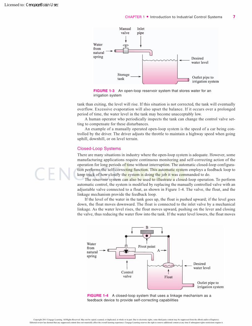
tank than exiting, the level will rise. If this situation is not corrected, the tank will eventuallyoverflow. Excessive evaporation will also upset the balance. If it occurs over a prolongedperiod of time, the water level in the tank may become unacceptably low.
A human operator who periodically inspects the tank can change the control valve set-ting to compensate for these disturbances.
An example of a manually operated open-loop system is the speed of a car being con-trolled by the driver. The driver adjusts the throttle to maintain a highway speed when goinguphill, downhill, or on level terrain.
Closed-Loop SystemsThere are many situations in industry where the open-loop system is adequate. However, somemanufacturing applications require continuous monitoring and self-correcting action of theoperation for long periods of time without interruption. The automatic closed-loop configura-tion performs the self-correcting function. This automatic system employs a feedback loop tokeep track of how closely the system is doing the job it was commanded to do.
The reservoir system can also be used to illustrate a closed-loop operation. To performautomatic control, the system is modified by replacing the manually controlled valve with anadjustable valve connected to a float, as shown in Figure 1-4. The valve, the float, and thelinkage mechanism provide the feedback loop.
If the level of the water in the tank goes up, the float is pushed upward; if the level goesdown, the float moves downward. The float is connected to the inlet valve by a mechanicallinkage. As the water level rises, the float moves upward, pushing on the lever and closingthe valve, thus reducing the water flow into the tank. If the water level lowers, the float moves
CHAPTER 1 � Introduction to Industrial Control Systems 7
FIGURE 1-3 An open-loop reservoir system that stores water for anirrigation system
FIGURE 1-4 A closed-loop system that uses a linkage mechanism as afeedback device to provide self-correcting capabilities
81974_01_ch01_pg001-016.qxd 03/30/2005 01:58 PM Page 7
Copyright 2011 Cengage Learning. All Rights Reserved. May not be copied, scanned, or duplicated, in whole or in part. Due to electronic rights, some third party content may be suppressed from the eBook and/or eChapter(s).
Editorial review has deemed that any suppressed content does not materially affect the overall learning experience. Cengage Learning reserves the right to remove additional content at any time if subsequent rights restrictions require it.
Licensed to:
downward, pulling on the lever and opening the valve, thus admitting more water into thetank. To adjust for a desired level of water in the tank, the float is moved up or down on thefloat rod A.
Most automated manufacturing processes use closed-loop control. These systems thathave a self-regulation capability are designed to produce continuous balance.
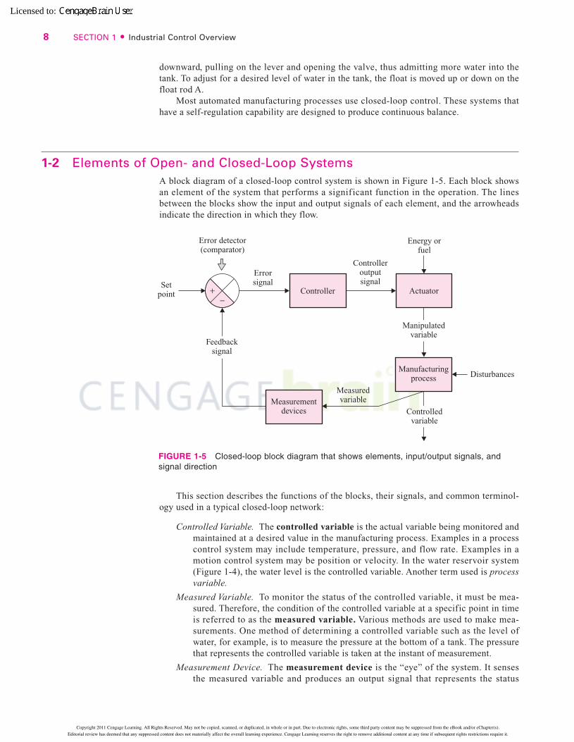
1-2 Elements of Open- and Closed-Loop SystemsA block diagram of a closed-loop control system is shown in Figure 1-5. Each block showsan element of the system that performs a signif icant function in the operation. The linesbetween the blocks show the input and output signals of each element, and the arrowheadsindicate the direction in which they flow.
This section describes the functions of the blocks, their signals, and common terminol-ogy used in a typical closed-loop network:
Controlled Variable. The controlled variable is the actual variable being monitored andmaintained at a desired value in the manufacturing process. Examples in a processcontrol system may include temperature, pressure, and flow rate. Examples in amotion control system may be position or velocity. In the water reservoir system(Figure 1-4), the water level is the controlled variable. Another term used is processvariable.
Measured Variable. To monitor the status of the controlled variable, it must be mea-sured. Therefore, the condition of the controlled variable at a specific point in timeis referred to as the measured variable. Various methods are used to make mea-surements. One method of determining a controlled variable such as the level ofwater, for example, is to measure the pressure at the bottom of a tank. The pressurethat represents the controlled variable is taken at the instant of measurement.
Measurement Device. The measurement device is the “eye” of the system. It sensesthe measured variable and produces an output signal that represents the status
8 SECTION 1 � Industrial Control Overview
FIGURE 1-5 Closed-loop block diagram that shows elements, input/output signals, andsignal direction
81974_01_ch01_pg001-016.qxd 03/30/2005 01:58 PM Page 8
Copyright 2011 Cengage Learning. All Rights Reserved. May not be copied, scanned, or duplicated, in whole or in part. Due to electronic rights, some third party content may be suppressed from the eBook and/or eChapter(s).
Editorial review has deemed that any suppressed content does not materially affect the overall learning experience. Cengage Learning reserves the right to remove additional content at any time if subsequent rights restrictions require it.
Licensed to:
of the controlled variable. Examples in a process control system may include athermocouple to measure temperature or a humidity detector to measure moisture.Examples in a motion control system may be an optical device to measure positionor a tachometer to measure rotational speed. In the water reservoir system, the floatis the measurement device. Other terms used are detector, transducer, and sensor.
Feedback Signal. The feedback signal is the output of the measurement device. In thewater reservoir system, the feedback signal is the vertical position of member A inthe linkage mechanism (see Figure 1-4). Other terms used are measured value,measurement signal, or position feedback if in a position loop, or velocity feedbackif in a velocity loop.
Set Point. The set point is the prescribed input value applied to the loop that indicatesthe desired condition of the controlled variable. The set point may be manually setby a human operator, automatically set by an electronic device, or programmed intoa computer. In the water reservoir system, the set point is determined by the posi-tion at which the float is placed along rod A. Other terms used are command, orreference.
Error Detector. The error detector compares the set point to the feedback signal. It thenproduces an output signal that is proportional to the difference between them. In thewater reservoir system, the error detector is the entire linkage mechanism. Otherterms used are comparator or comparer and summing junction.
Error Signal. The error signal is the output of the error detector. If the set point and thefeedback signal are not equal, an error signal proportional to their difference devel-ops. When the feedback and set point signals are equal, the error signal goes to zero.In the reservoir system (Figure 1-4), the error signal is the angular position of mem-ber B of the linkage mechanism. Other terms used are difference signal and deviation.
Controller. The controller is the “brain” of the system. It receives the error signal (forclosed-loop control) as its input, and develops an output signal that causes thecontrolled variable to become the value specified by the set point. Most controllers areoperated electronically, although some of the older process control systems use airpressure in pneumatic devices. The operation of an electronic controller is performedby hardwired circuitry or computer software. The controller produces a small electricalsignal that usually needs to be conditioned or modified before it is sent to the next ele-ment. For example, it must be amplified if it is applied to an electrical motor, or con-nected to a proportional air pressure if it is applied to a pneumatic positioner or acontrol valve. The control function is also performed by programmable logic con-trollers (PLCs) and panel-mounted microprocessor controllers.
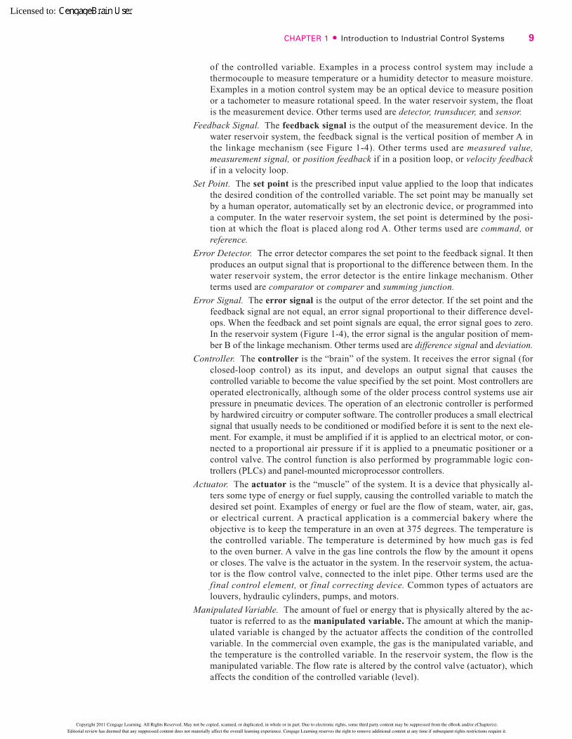
Actuator. The actuator is the “muscle” of the system. It is a device that physically al-ters some type of energy or fuel supply, causing the controlled variable to match thedesired set point. Examples of energy or fuel are the flow of steam, water, air, gas,or electrical current. A practical application is a commercial bakery where theobjective is to keep the temperature in an oven at 375 degrees. The temperature isthe controlled variable. The temperature is determined by how much gas is fedto the oven burner. A valve in the gas line controls the flow by the amount it opensor closes. The valve is the actuator in the system. In the reservoir system, the actua-tor is the flow control valve, connected to the inlet pipe. Other terms used are thefinal control element, or final correcting device. Common types of actuators arelouvers, hydraulic cylinders, pumps, and motors.
Manipulated Variable. The amount of fuel or energy that is physically altered by the ac-tuator is referred to as the manipulated variable. The amount at which the manip-ulated variable is changed by the actuator affects the condition of the controlledvariable. In the commercial oven example, the gas is the manipulated variable, andthe temperature is the controlled variable. In the reservoir system, the flow is themanipulated variable. The flow rate is altered by the control valve (actuator), whichaffects the condition of the controlled variable (level).
CHAPTER 1 � Introduction to Industrial Control Systems 9
81974_01_ch01_pg001-016.qxd 03/30/2005 01:58 PM Page 9
Copyright 2011 Cengage Learning. All Rights Reserved. May not be copied, scanned, or duplicated, in whole or in part. Due to electronic rights, some third party content may be suppressed from the eBook and/or eChapter(s).
Editorial review has deemed that any suppressed content does not materially affect the overall learning experience. Cengage Learning reserves the right to remove additional content at any time if subsequent rights restrictions require it.
Licensed to:
Manufacturing Process. The manufacturing process is the operation performed by theactuator to control a physical variable, such as the motion of a machine or the pro-cessing of a liquid.
Disturbance. A disturbance is a factor that upsets the manufacturing process beingperformed, causing a change in the controlled variable. In the reservoir system, thedisturbances are the rainfall and evaporation that alter the water level.
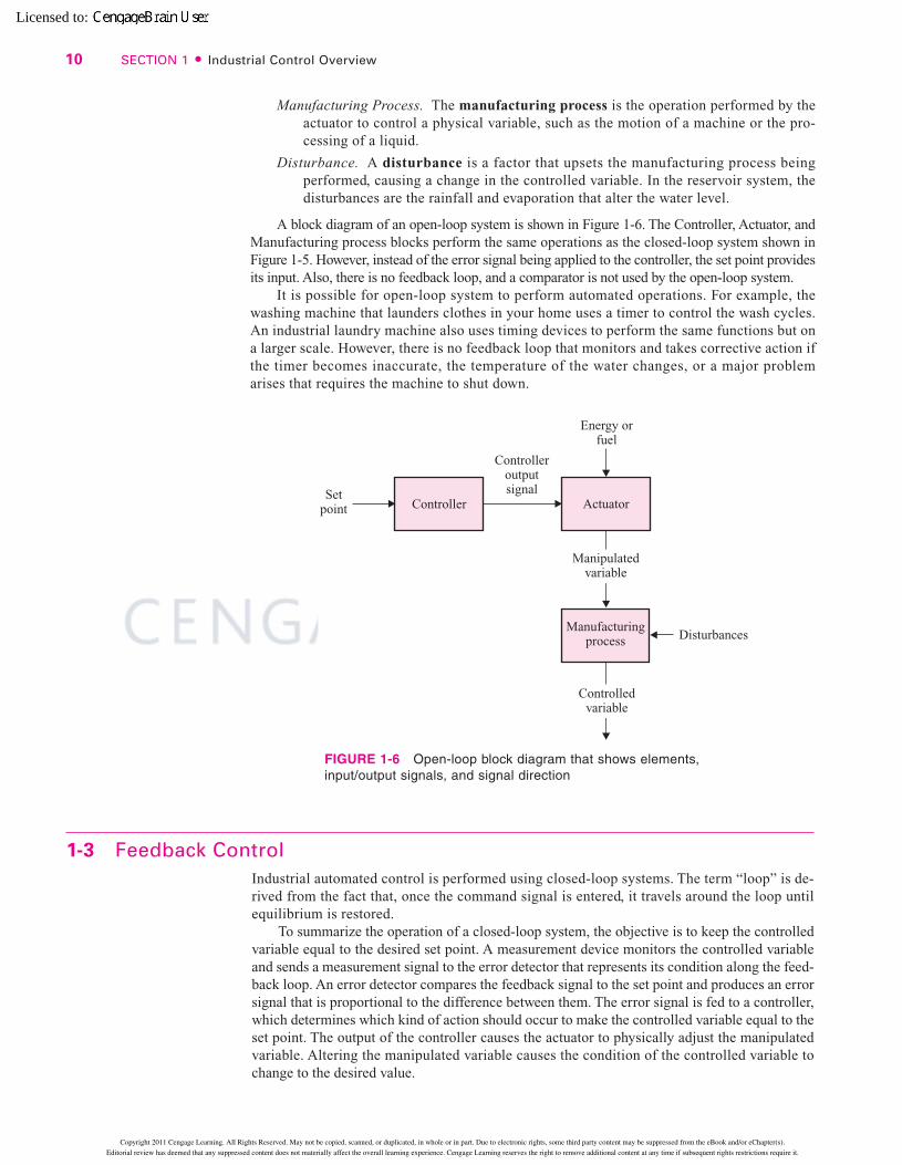
A block diagram of an open-loop system is shown in Figure 1-6. The Controller, Actuator, andManufacturing process blocks perform the same operations as the closed-loop system shown inFigure 1-5. However, instead of the error signal being applied to the controller, the set point providesits input. Also, there is no feedback loop, and a comparator is not used by the open-loop system.
It is possible for open-loop system to perform automated operations. For example, thewashing machine that launders clothes in your home uses a timer to control the wash cycles.An industrial laundry machine also uses timing devices to perform the same functions but ona larger scale. However, there is no feedback loop that monitors and takes corrective action ifthe timer becomes inaccurate, the temperature of the water changes, or a major problemarises that requires the machine to shut down.
10 SECTION 1 � Industrial Control Overview
FIGURE 1-6 Open-loop block diagram that shows elements,input/output signals, and signal direction
1-3 Feedback ControlIndustrial automated control is performed using closed-loop systems. The term “loop” is de-rived from the fact that, once the command signal is entered, it travels around the loop untilequilibrium is restored.
To summarize the operation of a closed-loop system, the objective is to keep the controlledvariable equal to the desired set point. A measurement device monitors the controlled variableand sends a measurement signal to the error detector that represents its condition along the feed-back loop. An error detector compares the feedback signal to the set point and produces an errorsignal that is proportional to the difference between them. The error signal is fed to a controller,which determines which kind of action should occur to make the controlled variable equal to theset point. The output of the controller causes the actuator to physically adjust the manipulatedvariable. Altering the manipulated variable causes the condition of the controlled variable tochange to the desired value.
81974_01_ch01_pg001-016.qxd 03/30/2005 01:59 PM Page 10
Copyright 2011 Cengage Learning. All Rights Reserved. May not be copied, scanned, or duplicated, in whole or in part. Due to electronic rights, some third party content may be suppressed from the eBook and/or eChapter(s).
Editorial review has deemed that any suppressed content does not materially affect the overall learning experience. Cengage Learning reserves the right to remove additional content at any time if subsequent rights restrictions require it.
Licensed to:
The basic concept of feedback control is that an error must exist before some correctiveaction can be made. An error can develop in one of three ways:
1. The set point is changed.
2. A disturbance appears.
3. The load demand varies.
In the reservoir system, the set point is changed by adjusting the position of the float alonglinkage A. A disturbance is caused when rain supplies additional water to the tank, or evapo-ration lowers the level. The water flowing out of the tank to the irrigation system is referredto as the load. If the level of the water in the irrigation system suddenly lowers, the backpressure on the outlet pipe will decrease and cause the fluid to drain faster. This downstreamcondition is referred to as a load change. The set point and load demand are changes thatnormally occur in a system. The disturbance is an unwanted condition.
Feedback signals may be either positive or negative. If the feedback signal’s polarity aidsa command input signal, it is said to be positive or regenerative feedback. Positive feedbackis used in radios. If the radio signal is weak, an Automatic Gain Control (AGC) circuit is ac-tivated. Its output is a feedback signal that boosts the radio signal’s overall strength.
However, when positive feedback is used in industrial closed-loop systems, the inputusually loses control over the output. If the feedback signal opposes the input signal, the sys-tem is said to use negative or degenerative feedback. By combining negative feedback valuesfrom the command signal, a closed-loop system works properly.
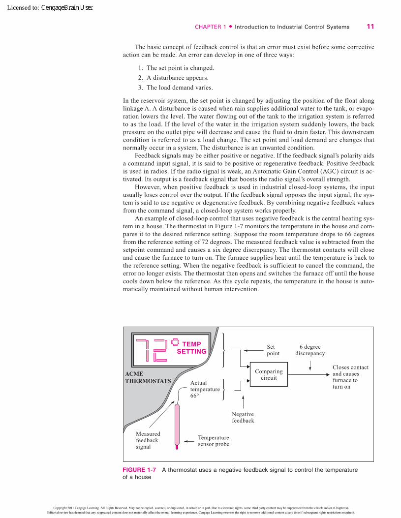
An example of closed-loop control that uses negative feedback is the central heating sys-tem in a house. The thermostat in Figure 1-7 monitors the temperature in the house and com-pares it to the desired reference setting. Suppose the room temperature drops to 66 degreesfrom the reference setting of 72 degrees. The measured feedback value is subtracted from thesetpoint command and causes a six degree discrepancy. The thermostat contacts will closeand cause the furnace to turn on. The furnace supplies heat until the temperature is back tothe reference setting. When the negative feedback is sufficient to cancel the command, theerror no longer exists. The thermostat then opens and switches the furnace off until the housecools down below the reference. As this cycle repeats, the temperature in the house is auto-matically maintained without human intervention.
CHAPTER 1 � Introduction to Industrial Control Systems 11
FIGURE 1-7 A thermostat uses a negative feedback signal to control the temperatureof a house
81974_01_ch01_pg001-016.qxd 03/30/2005 01:59 PM Page 11
Copyright 2011 Cengage Learning. All Rights Reserved. May not be copied, scanned, or duplicated, in whole or in part. Due to electronic rights, some third party content may be suppressed from the eBook and/or eChapter(s).
Editorial review has deemed that any suppressed content does not materially affect the overall learning experience. Cengage Learning reserves the right to remove additional content at any time if subsequent rights restrictions require it.
Licensed to:
The speed of an automobile can also be controlled automatically by a closed-loop sys-tem called a cruise control. The desired speed is set by an electronic mechanism usuallyplaced on the steering wheel assembly. A Hall-effect speed sensor connected to the front axlegenerates a signal proportional to actual speed. An electronic error detector compares the ac-tual speed to the desired speed, and then sends a signal representing the difference betweenthem to a controller. The controller sends a demand signal to a vacuum device called an actu-ator. A part of the vacuum mechanism is a rod connected to the throttle, which varies the fuelflow to the engine. If a car that is traveling on a level road suddenly encounters an uphillgrade, it begins to slow down. Because the actual speed is lower than the desired speed, theerror detector sends a signal to the actuator. A vacuum is varied, which causes the rod tomove the throttle so that more fuel flows to the engine. The additional fuel causes the car toaccelerate until it reaches the desired speed.
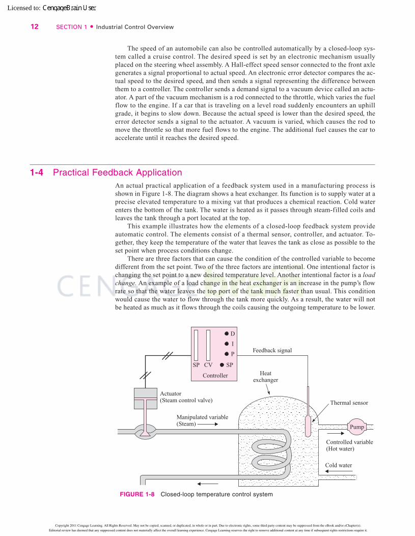
1-4 Practical Feedback ApplicationAn actual practical application of a feedback system used in a manufacturing process isshown in Figure 1-8. The diagram shows a heat exchanger. Its function is to supply water at aprecise elevated temperature to a mixing vat that produces a chemical reaction. Cold waterenters the bottom of the tank. The water is heated as it passes through steam-filled coils andleaves the tank through a port located at the top.
This example illustrates how the elements of a closed-loop feedback system provideautomatic control. The elements consist of a thermal sensor, controller, and actuator. To-gether, they keep the temperature of the water that leaves the tank as close as possible to theset point when process conditions change.
There are three factors that can cause the condition of the controlled variable to becomedifferent from the set point. Two of the three factors are intentional. One intentional factor ischanging the set point to a new desired temperature level. Another intentional factor is a loadchange. An example of a load change in the heat exchanger is an increase in the pump’s flowrate so that the water leaves the top port of the tank much faster than usual. This conditionwould cause the water to flow through the tank more quickly. As a result, the water will notbe heated as much as it flows through the coils causing the outgoing temperature to be lower.
12 SECTION 1 � Industrial Control Overview
FIGURE 1-8 Closed-loop temperature control system
81974_01_ch01_pg001-016.qxd 03/30/2005 01:59 PM Page 12
Copyright 2011 Cengage Learning. All Rights Reserved. May not be copied, scanned, or duplicated, in whole or in part. Due to electronic rights, some third party content may be suppressed from the eBook and/or eChapter(s).
Editorial review has deemed that any suppressed content does not materially affect the overall learning experience. Cengage Learning reserves the right to remove additional content at any time if subsequent rights restrictions require it.
Licensed to:
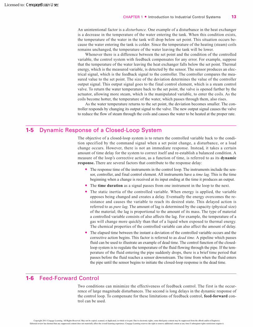
An unintentional factor is a disturbance. One example of a disturbance in the heat exchangeris a decrease in the temperature of the water entering the tank. When this condition exists,the temperature of the water in the tank will drop below set point. This situation occurs be-cause the water entering the tank is colder. Since the temperature of the heating (steam) coilsremains unchanged, the temperature of the water leaving the tank will be lower.
Whenever there is a difference between the set point and the condition of the controlledvariable, the control system with feedback compensates for any error. For example, supposethat the temperature of the water leaving the heat exchanger falls below the set point. Thermalenergy, which is the measured variable, is detected by the sensor. The sensor produces an elec-trical signal, which is the feedback signal to the controller. The controller compares the mea-sured value to the set point. The size of the deviation determines the value of the controlleroutput signal. This output signal goes to the final control element, which is a steam controlvalve. To return the water temperature back to the set point, the valve is opened farther by theactuator, allowing more steam, which is the manipulated variable, to enter the coils. As thecoils become hotter, the temperature of the water, which passes through them, also rises.
As the water temperature returns to the set point, the deviation becomes smaller. The con-troller responds by changing its output signal to the valve. The new output signal causes the valveto reduce the flow of steam through the coils and causes the water to be heated at the proper rate.
1-5 Dynamic Response of a Closed-Loop SystemThe objective of a closed-loop system is to return the controlled variable back to the condi-tion specif ied by the command signal when a set point change, a disturbance, or a loadchange occurs. However, there is not an immediate response. Instead, it takes a certainamount of time delay for the system to correct itself and re-establish a balanced condition. Ameasure of the loop’s corrective action, as a function of time, is referred to as its dynamicresponse. There are several factors that contribute to the response delay:
� The response time of the instruments in the control loop. The instruments include the sen-sor, controller, and final control element. All instruments have a time lag. This is the timebeginning when a change is received at its input ending at the time it produces an output.
� The time duration as a signal passes from one instrument in the loop to the next.� The static inertia of the controlled variable. When energy is applied, the variable
opposes being changed and creates a delay. Eventually the energy overcomes the re-sistance and causes the variable to reach its desired state. This delayed action isreferred to as pure lag. The amount of lag is determined by the capacity (physical size)of the material; the lag is proportional to the amount of its mass. The type of materiala controlled variable consists of also affects the lag. For example, the temperature of agas will change more quickly than that of a liquid when exposed to thermal energy.The chemical properties of the controlled variable can also affect the amount of delay.
� The elapsed time between the instant a deviation of the controlled variable occurs and thecorrective action begins. This factor is referred to as dead time. A pipeline which passesfluid can be used to illustrate an example of dead time. The control function of the closed-loop system is to regulate the temperature of the fluid flowing through the pipe. If the tem-perature of the fluid entering the pipe suddenly drops, there is a brief time period thatpasses before the fluid reaches a sensor downstream. The time from when the fluid entersthe pipe until the sensor begins to initiate the closed-loop response is the dead time.
1-6 Feed-Forward ControlTwo conditions can minimize the effectiveness of feedback control. The first is the occur-rence of large magnitude disturbances. The second is long delays in the dynamic response ofthe control loop. To compensate for these limitations of feedback control, feed-forward con-trol can be used.
CHAPTER 1 � Introduction to Industrial Control Systems 13
81974_01_ch01_pg001-016.qxd 03/30/2005 01:59 PM Page 13
Copyright 2011 Cengage Learning. All Rights Reserved. May not be copied, scanned, or duplicated, in whole or in part. Due to electronic rights, some third party content may be suppressed from the eBook and/or eChapter(s).
Editorial review has deemed that any suppressed content does not materially affect the overall learning experience. Cengage Learning reserves the right to remove additional content at any time if subsequent rights restrictions require it.
Licensed to:
The operation of feed-forward control is very different from feedback control. Feedback controltakes corrective action after an error develops. The objective of feed-forward control is to preventerrors from occurring. Typically, feed-forward cannot prevent errors. Instead, it minimizes them.
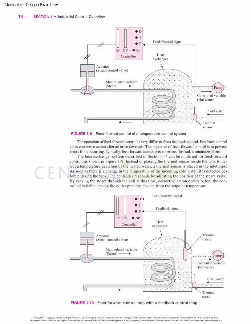
The heat exchanger system described in Section 1-4 can be modified for feed-forwardcontrol, as shown in Figure 1-9. Instead of placing the thermal sensor inside the tank to de-tect a temperature deviation of the heated water, a thermal sensor is placed in the inlet pipe.As soon as there is a change in the temperature of the incoming cold water, it is detected be-fore entering the tank. The controller responds by adjusting the position of the steam valve.By varying the steam through the coil at this time, corrective action occurs before the con-trolled variable leaving the outlet pipe can deviate from the setpoint temperature.
14 SECTION 1 � Industrial Control Overview
FIGURE 1-9 Feed-forward control of a temperature control system
FIGURE 1-10 Feed-forward control loop with a feedback control loop
81974_01_ch01_pg001-016.qxd 03/30/2005 01:59 PM Page 14
Copyright 2011 Cengage Learning. All Rights Reserved. May not be copied, scanned, or duplicated, in whole or in part. Due to electronic rights, some third party content may be suppressed from the eBook and/or eChapter(s).
Editorial review has deemed that any suppressed content does not materially affect the overall learning experience. Cengage Learning reserves the right to remove additional content at any time if subsequent rights restrictions require it.
Licensed to:
The feed-forward control system does not operate perfectly. There are always unmeasur-able disturbances that cannot be detected, such as a worn flow valve, a sensor out of tolerance,or inexact mathematical calculations processed by the controller. Over a period of time, theseunmeasurable disturbances affect the operation and eventually the water temperature in thetank, finally causing the water to reach an unacceptable temperature level. Due to the inaccu-racy of feed-forward control, it is seldom used by itself. By adding feedback control to thesystem, corrections to the controller can be made if the controlled variable deviates from theset point due to unmeasurable disturbances.
Figure 1-10 shows a heat exchanger system that uses both feed-forward and feedbackcontrol. The controller receives input signals from two sensors. The sensor in the inlet lineprovides the feed-forward signal, and the sensor near the outlet provides the feedback signal.
In summary, feed-forward control adjusts the operation of the actuator to preventchanges in the controlled variable. Feed-forward controllers must make very sophisticatedcalculations to compute the changes of the actuator needed to compensate for variations indisturbances. Since they require highly skilled engineers, they typically are used only incritical applications within the plant.
CHAPTER 1 � Introduction to Industrial Control Systems 15
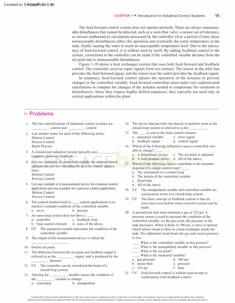
1. The two classifications of industrial control systems arecontrol and control.
2. List another name for each of the following terms.Motion ControlProcess ControlBatch Process
3. A closed-loop industrial system typically uses (negative, positive) feedback.
4. List two examples of controlled variables for motion controlapplications and two examples for process control applica-tions.Motion ControlProcess Control
5. List one example of a measurement device for a motion controlapplication and one example for a process control application.Motion ControlProcess Control
6. The control method used in control applications is tosustain a constant condition of the controlled variable.a. servo b. process
7. An open-loop system does not have a .a. controller c. feedback loopb. final control element d. none of the above
8. T/F The measured variable represents the condition of thecontrolled variable.
9. The output of the measurement device is called the.
10. Define set point.
11. The difference between the set point and feedback signal isreferred to as the signal, and is produced by the
detector.
12. T/F The controller can be considered the brain of aclosed-loop system.
13. Altering the variable causes the condition ofthe variable to change.a. controlled b. manipulated
14. The device that provides the muscle to perform work in theclosed-loop system is referred to as the .
15. The is sent to the final control element.a. measured variable c. error signalb. feedback signal d. control signal
16. Which of the following influences cause a controlled vari-able to change? a. A disturbance occurs. c. The set point is adjusted.b. A load demand varies. d. All of the above.
17. Which of the following factors contribute to the dynamicresponse of a single control loop? a. The instrument in a control loopb. The inertia of the controlled variablec. Dead timed. All of the above
18. T/F The manipulated variable and controlled variable aresynonymous terms in a closed-loop system.
19. T/F The basic concept of feedback control is that anerror must exist before some corrective action can bemade.
20. A pressurized tank must maintain a gas at 325 psi. Apressure sensor is used to measure the condition of thecontrolled variable. As the gas cools, the pressure in thetank decreases. When it drops to 300 psi, a valve is opened,which allows steam to flow to a heat exchanger inside thetank. The additional steam heats the gas and causes pressureto rise.
What is the controlled variable in this process?What is the manipulated variable in this process?What is the set point?What is the measured variable?
a. gas pressure d. 300 psib. steam flow e. pressurec. 325 psi f. heat
21. T/F Feed-forward control is seldom used except incombination with feedback control.
Problems
81974_01_ch01_pg001-016.qxd 03/30/2005 01:59 PM Page 15
Copyright 2011 Cengage Learning. All Rights Reserved. May not be copied, scanned, or duplicated, in whole or in part. Due to electronic rights, some third party content may be suppressed from the eBook and/or eChapter(s).
Editorial review has deemed that any suppressed content does not materially affect the overall learning experience. Cengage Learning reserves the right to remove additional content at any time if subsequent rights restrictions require it.
Licensed to:

22. Which of the following conditions are compensated forby using feed-forward control? a. Excessive lag time c. An error signalb. Large disturbances d. Feedback signal
23. The objective of control is to prevent the controlledvariable from deviating from the set point.a. feedback b. feed-forward
24. When feedback and feed-forward control are performedtogether, the primary function of feed-forward is to makecorrections for disturbances, and feedback control tomake corrections for disturbances.a. measurable b. unmeasurable
16 SECTION 1 � Industrial Control Overview
81974_01_ch01_pg001-016.qxd 03/30/2005 01:59 PM Page 16
Copyright 2011 Cengage Learning. All Rights Reserved. May not be copied, scanned, or duplicated, in whole or in part. Due to electronic rights, some third party content may be suppressed from the eBook and/or eChapter(s).
Editorial review has deemed that any suppressed content does not materially affect the overall learning experience. Cengage Learning reserves the right to remove additional content at any time if subsequent rights restrictions require it.
Licensed to:
Answers to Odd-Numbered Problems t
589
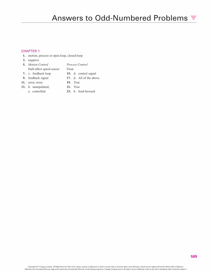
CHAPTER 11. motion, process or open-loop, closed-loop
3. negative
5. Motion Control Process Control
Hall-effect speed sensor Float
7. c. feedback loop 15. d. control signal
9. feedback signal 17. d. All of the above.
11. error, error 19. True
13. b. manipulated; 21. True
a. controlled 23. b. feed-forward
81974_24_Answer.qxd 03/30/2005 07:49 PM Page 589
Copyright 2011 Cengage Learning. All Rights Reserved. May not be copied, scanned, or duplicated, in whole or in part. Due to electronic rights, some third party content may be suppressed from the eBook and/or eChapter(s).
Editorial review has deemed that any suppressed content does not materially affect the overall learning experience. Cengage Learning reserves the right to remove additional content at any time if subsequent rights restrictions require it.