Embed Size (px)
Citation preview
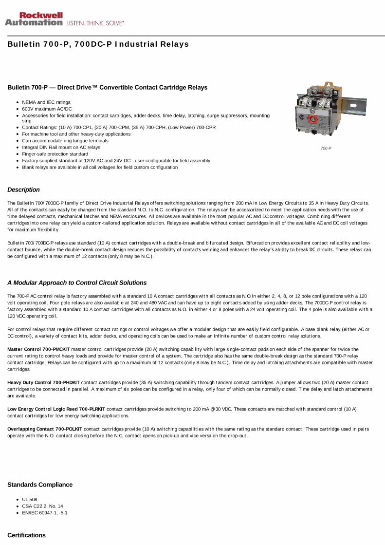
700-P
Bulletin 700-P, 700DC-P Industrial Relays
Bulletin 700P — Direct Drive™ Convertible Contact Cartridge Relays
NEMA and IEC ratings
600V maximum AC/DC
Accessories for field installation: contact cartridges, adder decks, time delay, latching, surge suppressors, mountingstrip
Contact Ratings: (10 A) 700-CP1, (20 A) 700-CPM, (35 A) 700-CPH, (Low Power) 700-CPR
For machine tool and other heavy-duty applications
Can accommodate ring tongue terminals
Integral DIN Rail mount on AC relays
Finger-safe protection standard
Factory supplied standard at 120V AC and 24V DC - user configurable for field assembly
Blank relays are available in all coil voltages for field custom configuration
Description
The Bulletin 700/700DC-P family of Direct Drive Industrial Relays offers switching solutions ranging from 200 mA in Low Energy Circuits to 35 A in Heavy Duty Circuits.
All of the contacts can easily be changed from the standard N.O. to N.C. configuration. The relays can be accessorized to meet the application needs with the use of
time delayed contacts, mechanical latches and NEMA enclosures. All devices are available in the most popular AC and DC control voltages. Combining different
cartridges into one relay can yield a custom-tailored application solution. Relays are available without contact cartridges in all of the available AC and DC coil voltages
for maximum flexibility.
Bulletin 700/700DC-P relays use standard (10 A) contact cartridges with a double-break and bifurcated design. Bifurcation provides excellent contact reliability and low-
contact bounce, while the double‐break contact design reduces the possibility of contacts welding and enhances the relay’s ability to break DC circuits. These relays canbe configured with a maximum of 12 contacts (only 8 may be N.C.).
A Modular Approach to Control Circuit Solutions
The 700-P AC control relay is factory assembled with a standard 10 A contact cartridges with all contacts as N.O.in either 2, 4, 8, or 12 pole configurations with a 120
volt operating coil. Four pole relays are also available at 240 and 480 VAC and can have up to eight contacts added by using adder decks. The 700DC-P control relay is
factory assembled with a standard 10 A contact cartridges with all contacts as N.O. in either 4 or 8 poles with a 24 volt operating coil. The 4 pole is also available with a
120 VDC operating coil.
For control relays that require different contact ratings or control voltages we offer a modular design that are easily field configurable. A base blank relay (either AC or
DC control), a variety of contact kits, adder decks, and operating coils can be used to make an infinite number of custom control relay solutions.
Master Control 700-PMCKIT master control cartridges provide (20 A) switching capability with large single-contact pads on each side of the spanner for twice the
current rating to control heavy loads and provide for master control of a system. The cartridge also has the same double-break design as the standard 700-P relay
contact cartridge. Relays can be configured with up to a maximum of 12 contacts (only 8 may be N.C.). Time delay and latching attachments are compatible with master
cartridges.
Heavy Duty Control 700-PHDKIT contact cartridges provide (35 A) switching capability through tandem contact cartridges. A jumper allows two (20 A) master contact
cartridges to be connected in parallel. A maximum of six poles can be configured in a relay, only four of which can be normally closed. Time delay and latch attachments
are available.
Low Energy Control Logic Reed 700-PLRKIT contact cartridges provide switching to 200 mA @ 30 VDC. These contacts are matched with standard control (10 A)
contact cartridges for low energy switching applications.
Overlapping Contact 700-POLKIT contact cartridges provide (10 A) switching capabilities with the same rating as the standard contact. These cartridge used in pairs
operate with the N.O. contact closing before the N.C. contact opens on pick-up and vice versa on the drop-out.
Standards Compliance
UL 508
CSA C22.2, No. 14
EN/IEC 60947-1, -5-1
Certifications

cULus Listed (File No. E14840, Guide NKCR/NKCR7)
CE Marked
ABS
Standard Contact Cartridge (10 A)
AC-Operated Relays - In-stock Contact Configurations
Contacts Contact Arrangementand Markings
Open Type, DIN Rail, or Relay Rail Mount (700-MP)
N.O.⋆ 120V AC 240V AC 480V AC
0 700-P000A1 — —
2 700-P200A1 — —
4 700-P400A1 700-P400A2 700-P400A4
8 700-P800A1 — —
12 700-P1200A1 — —
⋆ Factory assembled N.O. contacts can be easily to N.C. in the field.
DC-Operated Relays - In-stock Contact Configurations
Contacts Contact Arrangementand Markings
Open Type Relay Rail Mount ‡
N.O.⋆ 24V DC 120V DC
Cat. No. Cat. No.
0 700DC-P000Z24 —
4 700DC-P400Z24 700DC-P400Z1
8 700DC-P800Z24 —
⋆ Factory assembled N.O. contacts can be easily to N.C. in the field.
‡ For DIN Rail mounting, order Cat. No. 700‐DRA.
Base Blank Relay - Factory Assembled
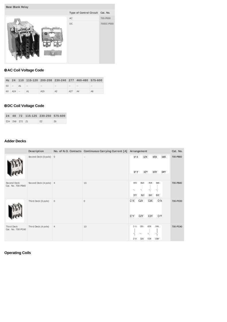
Base Blank Relay
Type of Control Circuit Cat. No.
AC 700-P000
DC 700DC-P000
ÄAC Coil Voltage Code
Hz 24 110 115-120 200-208 230-240 277 460-480 575-600
50 — A1 — — — — — —
60 A24 — A1 A20 A2 A27 A4 A6
ÄDC Coil Voltage Code
24 48 72 115-125 230-250 575-600
Z24 Z48 Z72 Z1 Z2 Z6
Adder Decks
Description No. of N.O. Contacts Continuous Carrying Current [A] Arrangement Cat. No.
Second Deck (0-pole) 0 — 700-PB00
Second DeckCat. No. 700-PB40
Second Deck (4-pole) 4 10 700-PB40
Third Deck (0-pole) 0 0 700-PC00
Third DeckCat. No. 700-PC40
Third Deck (4-pole) 4 10 700-PC40
Operating Coils

Bulletin 700P Relays — Bulletin 700PLLPKLL Mechanical Latch Attachments
CoilVolts⋆
Bulletin 700‐P, 2…12‐pole, AC control Bulletin 700‐PLL–PKLL AC Mechanical Latch Attachment Bulletin 700DC-P2…12‐pole,DC control
60 Hz 50 Hz 60 Hz 50 Hz DC —
24 PA013 PA407 PL013 PL407 PM714 PD714
48 — — — — PM724 PD724
72 — — — — PM730 PD730
110‡ — PA236 — PL236 — PD733 (100…110)
115…120‡ PA236 — PL236 — — —
110…115§ — PA322 — PL322 — —
115…125 — — — — PM735 PD735
Bulletin 700-POperating Coil
120§ PA322 — PL322 — — —
130…140 — — — — — PD738
200…208 PA249 — PL249 — — —
220…230 PA251 PA339 — PL339 — —
230…240 PA254 PA342 PL254 PL342 — —
230…250 — — — — PM748 PD748
277 PA260 — — — — —
380 — PA354 — PL354 PL354 —
415 — PA357 — PL357 PL357 —
440…460 — PA360 — PL360 PL360 —
Bulletin 700-PLUnlatch Coil andMagnet Assembly
460…480 PA273 — PL273 — — —
500 — PA364 — PL364 PL364 —
575…600 PA278 — PL278 — — PD758
⋆ Coils for AC relays cannot be used in DC relays and vice versa.
‡ This coil is optimized for 115…120V, 60 Hz applications and will operate satisfactorily at 110V, 50 Hz.
§ This coil is optimized for 110…115V, 50 Hz applications and will operate satisfactorily at 120V, 60 Hz.
ÄAC Coil Voltage Code
The Cat. No. as listed is incomplete. Select a voltage suffix code from the table below to complete the Cat. No. Example: Cat. No. 700-PLLÄ becomes Cat. No. 700-
PLLA1.
Hz 24 110 110-115 115-120 120 200-208 220-230 230-240 277 347 380 415 440-480 460-480 500 575-600
50 B24 A1♣ B11∆ — — — B22 B2 — — B3 B41 B44 — B50 —
60 A24 — — A1♣ B11∆ A20 A22 A2 A27 A35 — — — A4 — A6
♣ Optimized for 115…120V, 60 Hz. Operates satisfactorily at 110V, 50 Hz.
∆ Optimized for 110…115V, 50 Hz. Operates satisfactorily at 120V, 60 Hz.
ÄDC Coil Voltage Code
The Cat. No. as listed is incomplete. Select a voltage suffix code from the table below to complete the Cat. No. Example: Cat. No. 700DC-PLLÄ becomes Cat. No.
700DC-PLLZ24.
24 48 64 72 115-125 230-250 575-600
Z24 Z48 Z64 Z72 Z1 Z2 Z6
Contact Cartridges (Convertible from N.O. to N.C. and N.C. to N.O.)

Description Continuous CarryingCurrent[A]
Arrangement Pkg.Quantity
Cat. No.
Standard Contact CartridgeAC Rating NEMA A600DC Rating NEMA P600
10 1 700-CP1
Standard ContactCartridgeCat. No. 700-CP1, -CP11Z
Overlap Contact CartridgesOverlappingUsed in pairs. N.O. contact closes before N.C. contact opens on pick-up andvice versa on drop‐out.♦
AC RatingNEMA A600
10 2 700-CP11Z
DC RatingNEMA P150125V DC,138 VAMake andBreak
5
Master ContactCartridgeCat. No. 700-CPM
Master Contact CartridgeAC Rating Twice NEMA A600DC Rating NEMA N150 P600
20 1 700-CPM
Logic Reed Cartridge forLow Energy Circuits150V AC 500 mA 25 VA Max.30V DC 200 mA 6W Max.♠
Maximum150V AC
500 mA 1 700-CPR
Logic Reed CartridgeCat. No. 700-CPR
Maximum30V DC
200 mA
♦ Not Direct Drive.
♠ The 700‐CPR Logic Reed cartridge must be installed only in the 2nd deck (B1X ‐ B4X, B1Y ‐ B4Y position) or 3rd deck (C1X ‐ C4X, C1Y ‐ C4Y position) of the Bulletin 700 Type P relay. It is notrecommended that the 700-CPR cartridge be installed in the single deck (A1X - A4X, A1Y - A4Y position) because this may lead to improper operation.
Electrically Held Relays — Typical Wiring Diagrams

Bulletin 700-PS and -PSR Solid-State Timers
Description Continuous Carrying Current [A] Arrangement Timing Range▶ Cat. No.
Self-ContainedPotentiometer
On-Delay
5 0.1…2 700-PSAA1
0.4…8 700-PSBA1
1.5…30 700-PSCA1
6…120 700-PSDA1
Off-Delay 0.1…2 700-PSPA1
0.4…8 700-PSRA1
1.5…30 700-PSTA1
6…120 700-PSUA1
ExternalPotentiometer
On-Delay
5 0.1…2 s 700-PSRAA1
0.4…8 s 700-PSRBA1
1.5…30 s 700-PSRCA1
6…120 s 700-PSRDA1
Off-Delay 0.1…2 s 700-PSRPA1
0.4…8 s 700-PSRRA1
1.5…30 s 700-PSRTA1
6…120 s 700-PSRUA1
▶ Maximum time may be 50% greater and the minimum time may be 50% less than the value specified.
Remote Potentiometers for Cat. No. 700PSR…
Timing Range [s] Resistance [mW ] Cat. No.
0.1…2 0.75 700-N35
0.4…8 0.75 700-N35
1.5…30 2.0 700-N36
6…120 3.5 700-N37
Pneumatic Time-Delay Unit
Timing Range — 0.1…60 s0, 2, or 4 instantaneous contacts
Two timed contacts — both ON Delay or both OFF DelayConvertible from ON Delay to OFF Delay and vice versa
Standard contact cartridges rated NEMA A600 (AC) and P600 (DC)
Master contact cartridges rated 2X NEMA A600 (AC) and N150 P600 (DC)
Operating Mode No. of Timed Contacts# Continuous Carrying Current [A] Arrangement Timing Range Open TypeWithoutEnclosure&
N.O. N.C. Cat. No.
On-DelayOff-Delay
1 1 10 0.1…60 s 700-PT
Pneumatic Time-Delay 20 700-PKT
& Mounts on 4-pole Bulletin 700-P or -PK relay or 2-pole Bulletin 700-PH relay.
# In addition to instantaneous cartridges on the relay
Mechanical Latch Units
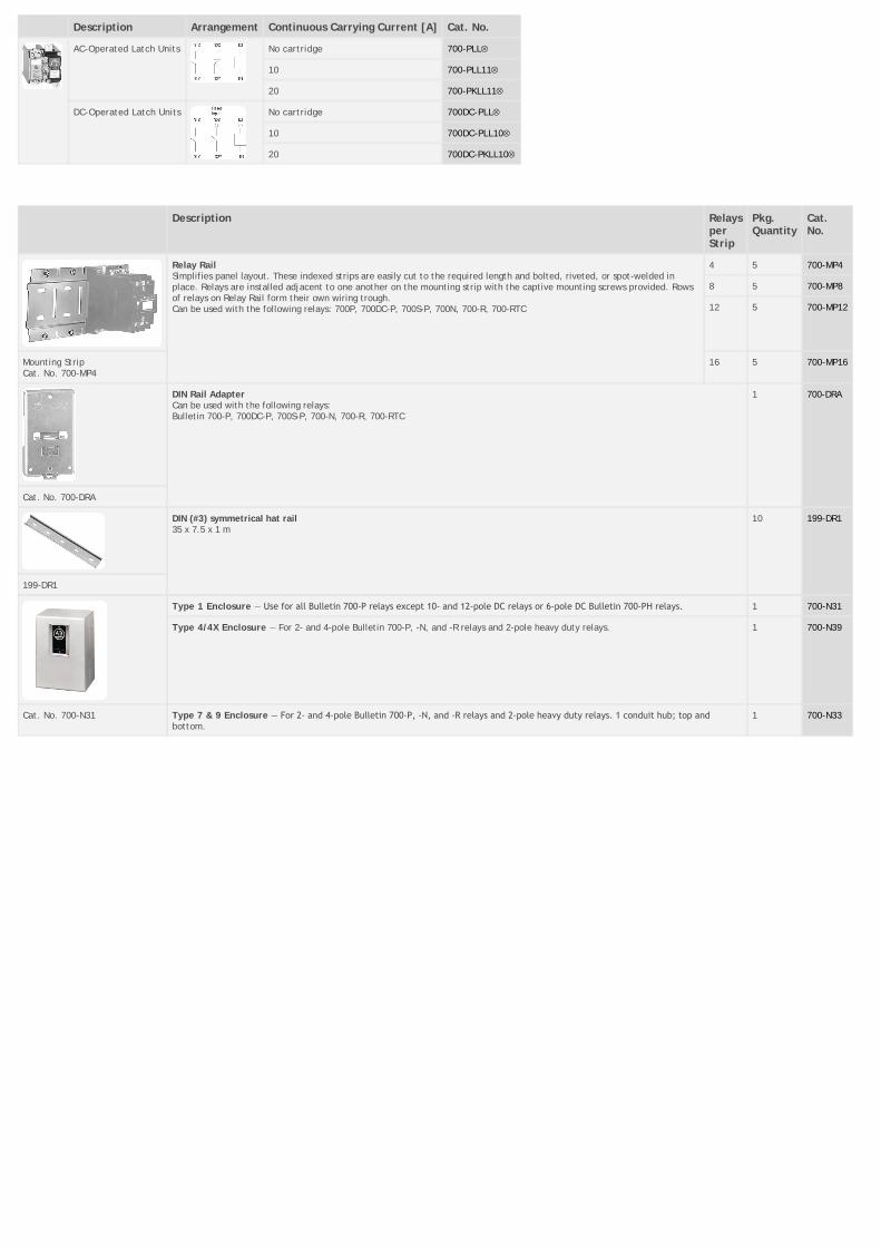
Description Arrangement Continuous Carrying Current [A] Cat. No.
AC-Operated Latch Units No cartridge 700-PLLÄ
10 700-PLL11Ä
20 700-PKLL11Ä
DC-Operated Latch Units No cartridge 700DC-PLLÄ
10 700DC-PLL10Ä
20 700DC-PKLL10Ä
Description RelaysperStrip
Pkg.Quantity
Cat.No.
Relay RailSimplifies panel layout. These indexed strips are easily cut to the required length and bolted, riveted, or spot-welded inplace. Relays are installed adjacent to one another on the mounting strip with the captive mounting screws provided. Rowsof relays on Relay Rail form their own wiring trough.Can be used with the following relays: 700P, 700DC-P, 700S-P, 700N, 700-R, 700-RTC
4 5 700-MP4
8 5 700-MP8
12 5 700-MP12
Mounting StripCat. No. 700-MP4
16 5 700-MP16
DIN Rail AdapterCan be used with the following relays:Bulletin 700-P, 700DC-P, 700S-P, 700-N, 700-R, 700-RTC
1 700-DRA
Cat. No. 700-DRA
DIN (#3) symmetrical hat rail35 x 7.5 x 1 m
10 199-DR1
199-DR1
Type 1 Enclosure — Use for all Bulletin 700‐P relays except 10‐ and 12‐pole DC relays or 6‐pole DC Bulletin 700‐PH relays. 1 700-N31
Type 4/4X Enclosure — For 2- and 4-pole Bulletin 700-P, -N, and -R relays and 2-pole heavy duty relays. 1 700-N39
Cat. No. 700-N31 Type 7 & 9 Enclosure — For 2‐ and 4‐pole Bulletin 700‐P, ‐N, and ‐R relays and 2‐pole heavy duty relays. 1 conduit hub; top andbottom.
1 700-N33

Description Pkg.Quantity
Cat. No.
Surge Suppressors (RC Circuit) — Surge suppressors reduce the high transient voltages generated when the coil circuit is opened.These suppressors can be used with Bulletin 700-P, -PH, -PK, and -N relays, and other electromechanical devices. They contain aresistor and capacitor. Maximum ratings: 150V, AC or DC, 35 VA. Cat. No. 700-N5 requires 1 in. additional depth of enclosure.
Mountingbehindrelay
1 700-N5
Surge SuppressorCat. No. 700-N5
Mountingon coilterminal
1 700-N24
Surge SuppressorCat. No. 700-N24
Surge SuppressorWhen the circuit to a DC operating coil is opened, the inductive energy stored in the coil can generate very high transient voltages.With the addition of the appropriate surge suppressor, the stored energy is absorbed and dissipated limiting the voltage spikes. Asurge suppressor is not required with AC 700-R or -RM relays because the AC operating coil transients are suppressed by a full waverectifier connected to the coil.
24…48VAC/DC
1 199-FSMA9
50…120VAC/DC
1 199-FSMA10
130…250VAC/DC
1 199-FSMA11
Surge SuppressorCat. No. 199-FSMA1
Diode Surge Suppressor — for 6…300V DC voltage coils. Used on Bulletin 700‐P, ‐PH, ‐PK, ‐N, ‐F, and ‐R relays. 1 199-FSMZ-1
35 A Jumper Kit – CSA Approved, UL ListedThis 35 A Jumper Kit can be used with any Bulletin 700-P and -PK AC or DC relay, Time-Delay relay or Latch Unit equipped with 20 A MasterCartridges. It does not require any additional panel space.Jumper Kit terminals are designed for one #8 AWG wire or two #10 AWG wires. When connecting the two 20 A Master Cartridges in parallel, it isimportant that they be the same configuration (Normally Open or Normally Closed).Jumpers can be added to any contact cartridge location on a relay except the two center poles because of the wide spacing. An adhesive label isincluded with each kit listing the contact ratings.
1 700-CPH
35 A Jumper KitCat. No. 700-CPH
Jumpers (Not applicable for Bulletin 700‐PH or ‐PK relays) – For connection between a middle pole and an outer pole on the left orright side of the relay.
Jumper– Forouterpoles
50 700-N3
JumperCat. No.700-N3
JumperCat. No.700-N4
Jumpers (Not applicable for Bulletin 700‐PH or ‐PK relays) – For connection between two middle poles. Jumper– Formiddlepoles
700-N4
Check Out Tool — Mechanically maintains the Bulletin 700-P, -PH, or -PK relay in the energized position for troubleshooting purposes. 1 700-N23
Check Out ToolCat. No. 700-N23
Adapter Plate — Simplified relay conversion. Allows you to use the existing mounting holes when you replace a Bulletin 700-B, -BR, -BX, or -D relaywith a Bulletin 700-P, -PH, or -PK relay.
700-N34
IP 2x Finger-Safe Cover Accessories
Description Pkg. Quantity Cat. No.
Top Covers (Covering Top Level Contact Screws)
IP2X Top Cover for 700-P 1 700-PFSC
Timer Top Cover Kit 1 700-PFSTC
Latch Top Cover Kit (for Relays with Mechanical Latch Attachment) 1 700-PFSLCK
Timer Top Cover Kit, (for Master Cont. Relays with Pneumatic Timer) 1 700-PFSKTC
Latch Top Cover Kit (for Master Cont. Relays with Mechanical Latch) 1 700-PFSKLCK
Deck Covers (Covering all terminals not on top deck, only for multi-deck relays)
IP2X Deck Cover for all AC & DC Relays in the 700P Range 1 700-PFSDEK
Coil Covers
IP2X Coil Cover for all AC Relays in the 700P Range 1 700-PFSACC
IP2X Coil Cover for all DC Relays in the 700P Range 1 700-PFSDCC

Type Standard Cartridge Master Cartridge Heavy duty
Bulletin No. 700-P 700-PMKIT 700-PHDKIT
Electrical
Contact Rating Continuous 10 A @ 600V AC5 A @ 600V DC
20 A @ 600V AC10 A @ 600V DC
35 A @ 600V AC20 A @ 600V DC
RatingsMake/Break
AC NEMA A600 2 x NEMA A600 2 x NEMA A600
DC NEMA P600 N150 P600 N150 P600
Additional Contact Ratings for AC single-phase loads
— 3 Hp @ 240V AC - N.O.2 Hp @ 240V AC - N.O./N.C.1 Hp @ 120V AC - N.O./N.C.20 A Resistive Heating to 600V AC20 A Tungsten Lighting Load to 480V AC
5 Hp @ 240V AC - N.O.3 Hp @ 240V AC - N.O./N.C.2 Hp @ 120V AC - N.O./N.C.35 A General Use At 0.75 PF to 600V AC35 A Tungsten Lighting Load to 480V AC
DC CurrentRatings Make/Break
Cartridge Cat. No. 700-CP1 Cartridge Cat. No. 700-CPM Cartridge Cat. No. 700-CPH
DC SwitchingInductive Load
Contacts in Series Volts DC
24 64 125 250 500 600 24 64 125 250 500 600 24 64 125 250 500 600
480W 480W 275W 138W 135W 120W
1 5 A 2.2 A 1.1 A .55 A .24 A .2 A 10 A 5 A 2.2 A .55 A .24 A .2 A 10 A 5 A 2.2 A .55 A .24 A .2 A
2 10 A 10 A 5 A 2 A .7 A .5 A 20 A 10 A 5 A 2 A .7 A .5 A 20 A 10 A 5 A 2 A .7 A .5 A
3 — — 7 A 3 A 1.5 A 1.0 A — 15 A 7 A 3 A 1.5 A 1.0 A — 15 A 7 A 3 A 1.5 A 1.0 A
4 — — 10 A 5 A 2.5 A 1.5 A — 20 A 10 A 5 A 2.5 A 1.5 A — 20 A 10 A 5 A 2.5 A 1.5 A
Coil Voltage Range AC 85…110% 85…110% 85…110%
DC 80…110% 80…110% 80…110%
Battery Charging 85…115% 85…115% 85…115%
CoilConsumption
50 Hz 60 Hz 50 Hz 60 Hz 50 Hz 60 Hz
AC
Inrush 132VA‡ 138VA‡ 132VA‡ 138VA‡ 132VA‡ 138VA‡
Sealed 19.3VA‡ 19VA‡ 19.3 VA‡ 19VA‡ 19.3VA‡ 19VA‡
DC
Inrush 12.7VA‡ 12.7VA‡ 12.7VA‡
Sealed 12.7VA‡ 12.7VA‡ 12.7VA‡
PLL - PKLLAC Latch Unit
Inrush 15VA‡ 15.6VA‡ 5VA‡ 15.6VA‡ 15VA‡ 15.6VA‡
Sealed 5.4VA‡ 5.5VA‡ 5.4VA‡ 5.5VA‡ 5.4VA‡ 5.5VA‡
PLL - PKLLDC Latch Unit
Unlatch 35VA‡ 35VA‡ —
Intermittent 35 W‡ 35 W‡ —
Reset Time PT – PKT 75 ms 75 ms —
Minimum Pulse PLL–PKLL 75 ms 75 ms —
Mechanical
Operating Time Pickup AC – 10…20 msDC – 30…50 ms
AC – 10…20 msDC – 30…50 ms
AC – 10…20 msDC – 30…50 ms
Dropout AC – 10…20 msDC – 20…33 ms
AC – 10…20 msDC – 20…33 ms
AC – 10…20 msDC – 20…33 ms
Mechanical Life 10 million operations
Construction
Contact Arrangement Up to 12 Poles, Convertible to N.O. or N.C. (8N.C. Maximum)
Up to 12 Poles, Convertible to N.O. or N.C. (8N.C. Maximum)
Up to 6 Poles, Convertible to N.O. or N.C. (4N.C. Maximum)
Contact Material Silver Nickel Silver Cadmium Oxide Silver Cadmium Oxide
Mounting Panel, Strip Mount, or DIN RailHorizontal Mounting Recommended
Panel, Strip Mount, or DIN RailHorizontal Mounting Recommended
Panel, Strip Mount, or DIN RailHorizontal Mounting Recommended
Environmental
Temperature Operating⋆ –20…+65 °C (–4…149 °F) –20…+65 °C (–4…149 °F) –20…+65 °C (–4…149 °F)
Storage –40…+65 °C (–40…149 °F) –40…+65 °C (–40…149 °F) –40…+65 °C (–40…149 °F)
Wire Terminations
Wire size per UL/CSA #18 AWG…(2) #12 AWG
Tightening Torque 8…12 lb•in (0.9…1.4 N•m)
⋆ Temperature inside the panel.
‡ Average value for all coils within range. For values on a specific coil voltage, contact your local Rockwell Automation sales office or Allen‐Bradley distributor.
International Symbol for Mechanically Linked Contacts

Copyright © 2014 Rockwell Automation, Inc. All Rights Reserved.