Embed Size (px)
Citation preview
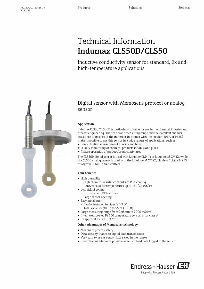
Digital sensor with Memosens protocol or analogsensor
Application
Indumax CLS50/CLS50D is particularly suitable for use in the chemical industry andprocess engineering. The six-decade measuring range and the excellent chemicalresistance properties of the materials in contact with the medium (PFA or PEEK)make it possible to use this sensor in a wide ranges of applications, such as:• Concentration measurement of acids and bases• Quality monitoring of chemical products in tanks and pipes• Phase separation of product/product mixturesThe CLS50D digital sensor is used with Liquiline CM44x or Liquiline M CM42, whilethe CLS50 analog sensor is used with the Liquiline M CM42, Liquisys CLM223/253or Mycom CLM153 transmitters.
Your benefits
• High durability– High chemical resistance thanks to PFA coating– PEEK version for temperatures up to 180 °C (356 °F)
• Low risk of soiling– Dirt-repellent PFA surface– Large sensor opening
• Easy installation– Can be installed in pipes ≥ DN 80– Total cable length up to 55 m (180 ft)
• Large measuring range from 2 μS/cm to 2000 mS/cm• Integrated, coated Pt 100 temperature sensor, error class A• Ex approval Ex ia IIC T4/T6
Other advantages of Memosens technology
• Maximum process safety• Data security thanks to digital data transmission• Very easy to use as sensor data saved in the sensor• Predictive maintenance possible as sensor load data logged in the sensor
Products Solutions Services
Technical InformationIndumax CLS50D/CLS50Inductive conductivity sensor for standard, Ex andhigh-temperature applications
TI00182C/07/EN/16.1571280313
Indumax CLS50D/CLS50
2 Endress+Hauser
Function and system design
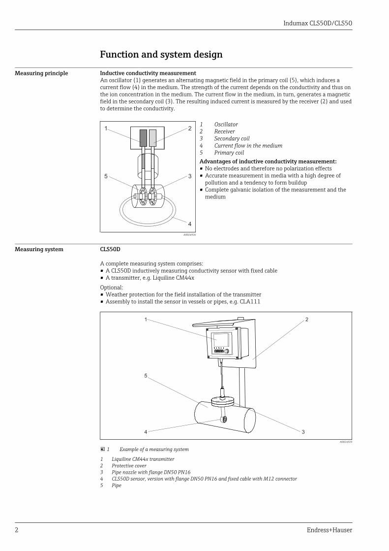
Measuring principle Inductive conductivity measurementAn oscillator (1) generates an alternating magnetic field in the primary coil (5), which induces acurrent flow (4) in the medium. The strength of the current depends on the conductivity and thus onthe ion concentration in the medium. The current flow in the medium, in turn, generates a magneticfield in the secondary coil (3). The resulting induced current is measured by the receiver (2) and usedto determine the conductivity.
1 2
3
4
5
A0024926
12345
OscillatorReceiverSecondary coilCurrent flow in the mediumPrimary coil
Advantages of inductive conductivity measurement:• No electrodes and therefore no polarization effects• Accurate measurement in media with a high degree of
pollution and a tendency to form buildup• Complete galvanic isolation of the measurement and the
medium
Measuring system CLS50D
A complete measuring system comprises:• A CLS50D inductively measuring conductivity sensor with fixed cable• A transmitter, e.g. Liquiline CM44xOptional:• Weather protection for the field installation of the transmitter• Assembly to install the sensor in vessels or pipes, e.g. CLA111
1 2
34
5
A0024929
1 Example of a measuring system
1 Liquiline CM44x transmitter2 Protective cover3 Pipe nozzle with flange DN50 PN164 CLS50D sensor, version with flange DN50 PN16 and fixed cable with M12 connector5 Pipe
Indumax CLS50D/CLS50
Endress+Hauser 3
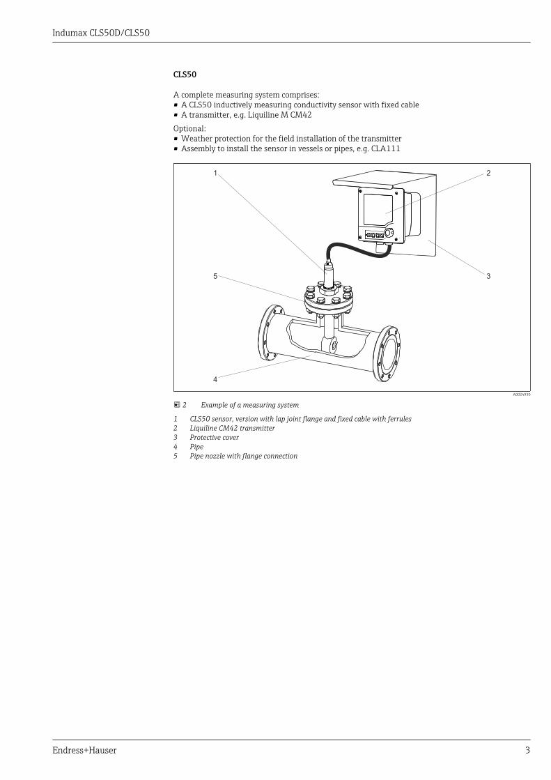
CLS50
A complete measuring system comprises:• A CLS50 inductively measuring conductivity sensor with fixed cable• A transmitter, e.g. Liquiline M CM42Optional:• Weather protection for the field installation of the transmitter• Assembly to install the sensor in vessels or pipes, e.g. CLA111
21
3
4
5
A0024930
2 Example of a measuring system
1 CLS50 sensor, version with lap joint flange and fixed cable with ferrules2 Liquiline CM42 transmitter3 Protective cover4 Pipe5 Pipe nozzle with flange connection

Indumax CLS50D/CLS50
4 Endress+Hauser
Communication and data processing (CLS50D only)Communication with the transmitter
Always connect digital sensors with Memosens technology to a transmitter with Memosenstechnology. Data transmission to a transmitter for analog sensors is not possible.
Digital sensors are able to store the following system data in the sensor:• Manufacturing data
– Serial number– Order code– Date of manufacture
• Calibration data– Calibration date– Cell constant– Delta cell constant– Number of calibrations– Serial number of the transmitter used for the last calibration
• Application data– Temperature application range– Conductivity application range– Date of first commissioning– Maximum temperature value– Hours of operation at high temperatures
Input
Measured variables • Conductivity• Temperature
Measuring ranges Conductivity 2 μS/cm to 2000 mS/cm (uncompensated)Temperature -20 to +180 °C (-4 to +350 °F)
Cell constant k = 1.98 cm–1
Measuring frequency 2 kHz
Temperature measurement CLS50D
Pt 1000 (Class A according to IEC 60751)
CLS50
Pt 100 (Class A according to IEC 60751)

Indumax CLS50D/CLS50
Endress+Hauser 5
Power supply
Electrical connection The sensor is supplied with a fixed cable. The cable between the sensor and transmitter can beextended using the CYK11 (CLS50D) or CLK6 (CLS50) special measuring cable (does not apply foruse in a hazardous environment).
GY
GY
GN
WH
BN
YE
PK
Shield
-
Com A
-
+
Com B
+
MemosensU
U
Additionalsensor supply
A0017984
3 CYK11 for extension for CLS50D
Max. total cable length: 100 m (330 ft)
WH
RD
Pt 1
00
YE
GN
RD
WH
BU
BN n.c.
RD
BU
A0024937
4 CLK6 for extension for CLS50
Max. total cable length: 55 m (180 ft)
CLS50 only:The residual coupling of the sensor increases when the fixed cable is extended.
Performance characteristics
Conductivity response time t95 ≤ 2 s
Temperature response time PEEK version: t90 ≤ 7 minPFA version: t90 ≤ 11 min
Maximum measured error -20 to 100 °C (-4 to 212 °F): ±(5 μS/cm + 0.5 % of reading)> 100 °C (212 °F): ±(10 μS/cm + 0.5 % of reading)
Repeatability 0.2% of reading
Linearity 1.9 % (only applies in the 1 to 20 mS/cm measuring range)
Indumax CLS50D/CLS50
6 Endress+Hauser
Installation
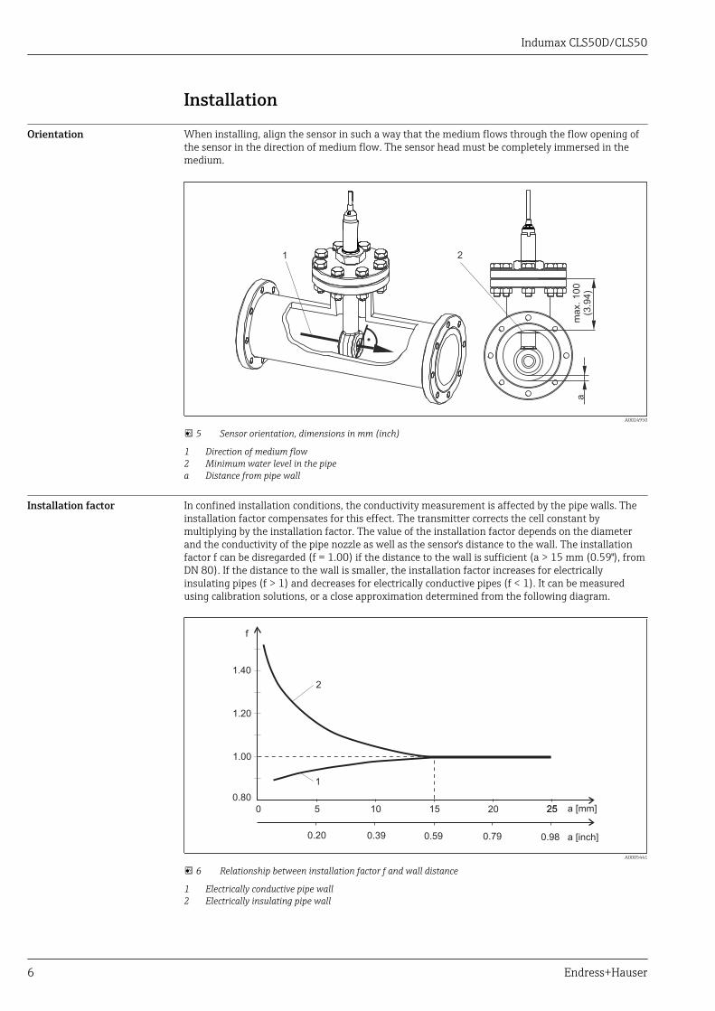
Orientation When installing, align the sensor in such a way that the medium flows through the flow opening ofthe sensor in the direction of medium flow. The sensor head must be completely immersed in themedium.
1 2
am
ax. 100
(3.9
4)
A0024950
5 Sensor orientation, dimensions in mm (inch)
1 Direction of medium flow2 Minimum water level in the pipea Distance from pipe wall
Installation factor In confined installation conditions, the conductivity measurement is affected by the pipe walls. Theinstallation factor compensates for this effect. The transmitter corrects the cell constant bymultiplying by the installation factor. The value of the installation factor depends on the diameterand the conductivity of the pipe nozzle as well as the sensor's distance to the wall. The installationfactor f can be disregarded (f = 1.00) if the distance to the wall is sufficient (a > 15 mm (0.59"), fromDN 80). If the distance to the wall is smaller, the installation factor increases for electricallyinsulating pipes (f > 1) and decreases for electrically conductive pipes (f < 1). It can be measuredusing calibration solutions, or a close approximation determined from the following diagram.
1
2
a [inch]
0 5 10 15 20 2525 a [mm]
0.80
1.00
1.20
1.40
f
0.20 0.39 0.59 0.79 0.98
A0005441
6 Relationship between installation factor f and wall distance
1 Electrically conductive pipe wall2 Electrically insulating pipe wall

Indumax CLS50D/CLS50
Endress+Hauser 7
Air set CLS50D
The digital sensor has already been adjusted at the factory. Onsite compensation is not required.
CLS50
To compensate residual coupling in the cable and between the two sensor coils, zero adjustment inair ("air set") must be performed before installing the sensor. Follow the instructions provided in theOperating Instructions of the transmitter used.
Installation with flange The sensor is suitable for installation in T-pieces ≥ DN 80, with the outgoing diameter reduced to ≥DN 50.
LWARNINGLeakageRisk of injury if medium escapes‣ Tighten the sensor nut with a torque of 20 Nm.‣ To avoid leakages, regularly check the tightness of the nut.
Flange, not in contact with medium
1 2
3
5
4
A0024949
7 Fixed flange, not in contact with medium (for order option: "Process connection" = 5, 6, 7)
1 Flange (stainless steel)2 Nut3 Sealing disk (GYLON)4 O-ring5 Sensor

Indumax CLS50D/CLS50
8 Endress+Hauser
Flange, in contact with medium
1 2
4 3
A0024953
8 Fixed flange, in contact with medium (for order option: "Process connection" = 3, 4)
1 Flange (stainless steel)2 Nut3 O-ring4 Sensor
Lap joint flange, not in contact with medium
1 2
35
4
A0024954
9 Lap joint flange, not in contact with medium (for order option: "Process connection" = A, B, C)
1 Lap joint flange (PP-GF)2 Nut (stainless steel)3 Flange (PVDF)4 O-ring5 Sensor
Indumax CLS50D/CLS50
Endress+Hauser 9
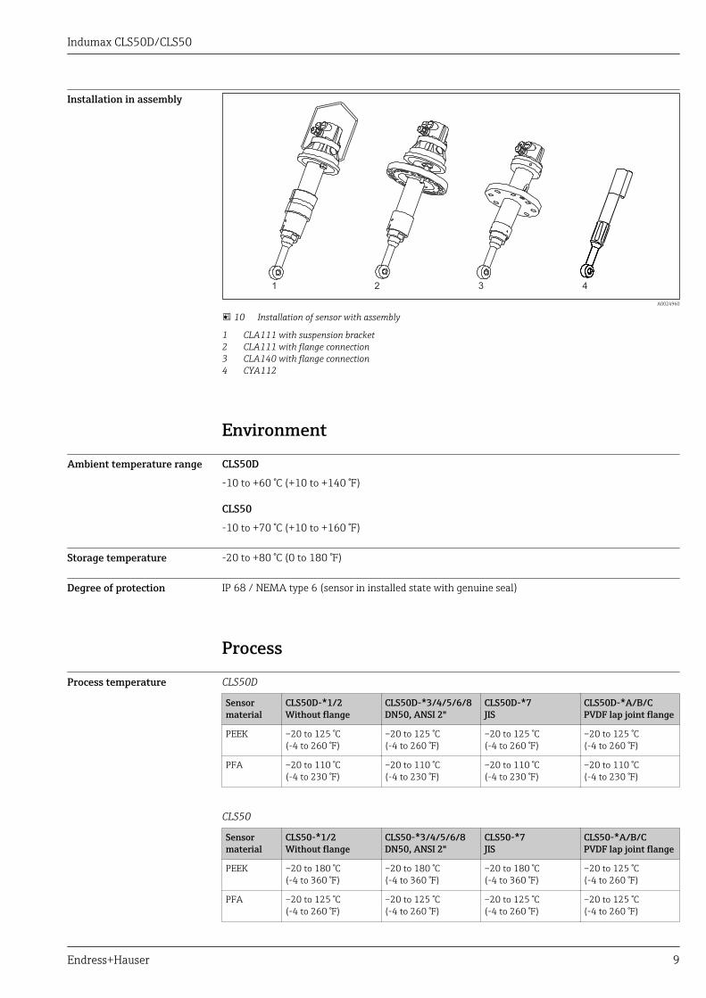
Installation in assembly
1 2 3 4
A0024960
10 Installation of sensor with assembly
1 CLA111 with suspension bracket2 CLA111 with flange connection3 CLA140 with flange connection4 CYA112
Environment
Ambient temperature range CLS50D
-10 to +60 °C (+10 to +140 °F)
CLS50
-10 to +70 °C (+10 to +160 °F)
Storage temperature -20 to +80 °C (0 to 180 °F)
Degree of protection IP 68 / NEMA type 6 (sensor in installed state with genuine seal)
Process
Process temperature CLS50D
Sensormaterial
CLS50D-*1/2Without flange
CLS50D-*3/4/5/6/8DN50, ANSI 2"
CLS50D-*7JIS
CLS50D-*A/B/CPVDF lap joint flange
PEEK –20 to 125 °C(-4 to 260 °F)
–20 to 125 °C(-4 to 260 °F)
–20 to 125 °C(-4 to 260 °F)
–20 to 125 °C(-4 to 260 °F)
PFA –20 to 110 °C(-4 to 230 °F)
–20 to 110 °C(-4 to 230 °F)
–20 to 110 °C(-4 to 230 °F)
–20 to 110 °C(-4 to 230 °F)
CLS50
Sensormaterial
CLS50-*1/2Without flange
CLS50-*3/4/5/6/8DN50, ANSI 2"
CLS50-*7JIS
CLS50-*A/B/CPVDF lap joint flange
PEEK –20 to 180 °C(-4 to 360 °F)
–20 to 180 °C(-4 to 360 °F)
–20 to 180 °C(-4 to 360 °F)
–20 to 125 °C(-4 to 260 °F)
PFA –20 to 125 °C(-4 to 260 °F)
–20 to 125 °C(-4 to 260 °F)
–20 to 125 °C(-4 to 260 °F)
–20 to 125 °C(-4 to 260 °F)

Indumax CLS50D/CLS50
10 Endress+Hauser
Process pressure (absolute) Max. 21 bar (305 psi), depending on the sensor version, see pressure-temperature ratings
Temperature-pressureratings
CLS50D
21
17
11
–20 +20125
1
2 3
4
[°C]
[bar]
[°F]
[psi]
247
160
–4 257+68
5
110
230
0
+23
1006040 80
ExPFA
T
p (abs.)
1
305
15
A0024981
11 Pressure-temperature ratings CLS50D
1 PEEK sensor, without a flange2 PFA sensor, without a flange (blue line)3 PEEK or PFA sensor, with DN50/ANSI 2" flange (red line)4 PEEK or PFA sensor, with JIS flange5 PEEK or PFA sensor, with PVDF lap joint flange (green line)
CLS50
21
17
11
–20 +20125
180
1
2 3
4
[°C]
[bar]
[°F]
[psi]
247
160
–4 257 356+68
5
0
+23
10060 140 16040 80
6
T
p (abs.)
305
115
A0024979
12 Pressure-temperature ratings for CLS50
1 PEEK sensor, without a flange2 PFA sensor, without a flange or with DN50/ANSI 2" flange (blue line)3 PEEK sensor, with DN50/ANSI 2" flange (red line)4 PFA sensor, with JIS flange (black line)5 PEEK or PFA sensor, with PVDF lap joint flange (green line)6 PEEK sensor, with JIS flange (gray line)
Indumax CLS50D/CLS50
Endress+Hauser 11
Mechanical construction
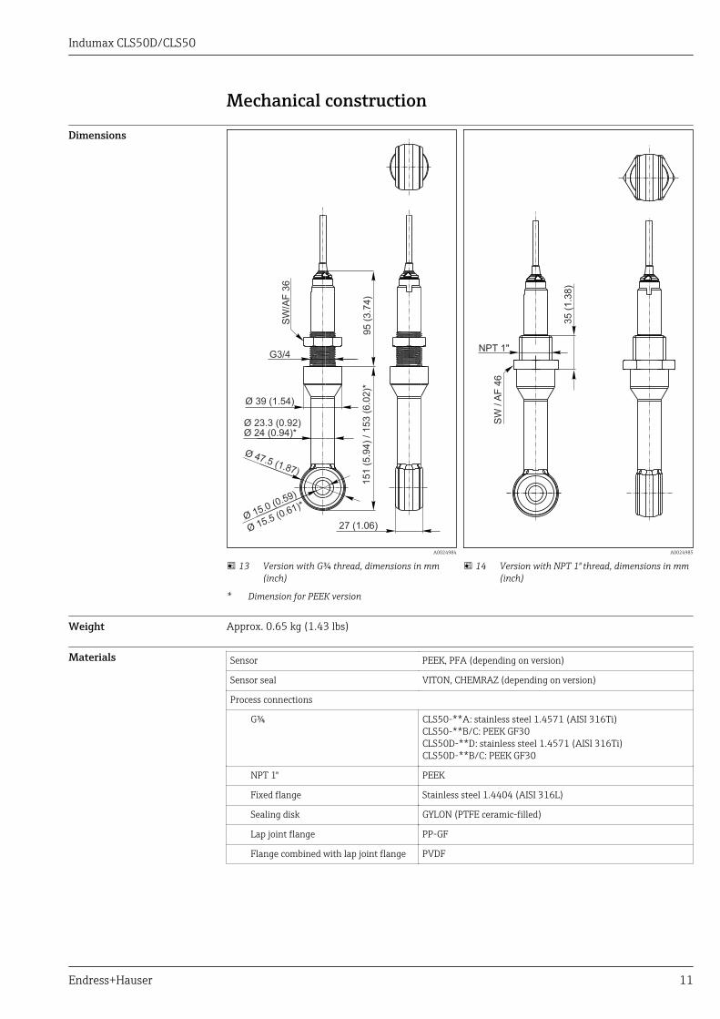
Dimensions
27 (1.06)
Ø 24 (0.94)*
Ø 39 (1.54)
Ø 15.0 (0.59)
Ø 47.5 (1.87)
SW
/AF
36
G3/495 (
3.7
4)
151 (
5.9
4)
/ 153 (
6.0
2)*
Ø 15.5 (0.61)*
Ø 23.3 (0.92)
A0024984
13 Version with G¾ thread, dimensions in mm(inch)
* Dimension for PEEK version
NPT 1"
SW
/A
F 4
6
35 (
1.3
8)
A0024985
14 Version with NPT 1" thread, dimensions in mm(inch)
Weight Approx. 0.65 kg (1.43 lbs)
Materials Sensor PEEK, PFA (depending on version)
Sensor seal VITON, CHEMRAZ (depending on version)
Process connections
G¾ CLS50-**A: stainless steel 1.4571 (AISI 316Ti)CLS50-**B/C: PEEK GF30CLS50D-**D: stainless steel 1.4571 (AISI 316Ti)CLS50D-**B/C: PEEK GF30
NPT 1" PEEK
Fixed flange Stainless steel 1.4404 (AISI 316L)
Sealing disk GYLON (PTFE ceramic-filled)
Lap joint flange PP-GF
Flange combined with lap joint flange PVDF
Indumax CLS50D/CLS50
12 Endress+Hauser
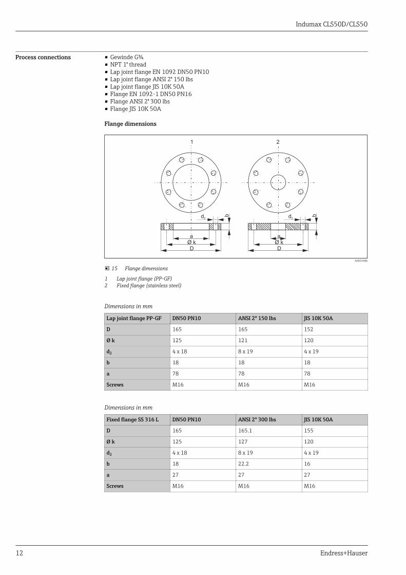
Process connections • Gewinde G¾• NPT 1" thread• Lap joint flange EN 1092 DN50 PN10• Lap joint flange ANSI 2" 150 lbs• Lap joint flange JIS 10K 50A• Flange EN 1092-1 DN50 PN16• Flange ANSI 2" 300 lbs• Flange JIS 10K 50A
Flange dimensions
d2
a
Ø k
D
b d2
a
Ø k
D
b
1 2
A0024986
15 Flange dimensions
1 Lap joint flange (PP-GF)2 Fixed flange (stainless steel)
Dimensions in mm
Lap joint flange PP-GF DN50 PN10 ANSI 2" 150 lbs JIS 10K 50A
D 165 165 152
Ø k 125 121 120
d2 4 x 18 8 x 19 4 x 19
b 18 18 18
a 78 78 78
Screws M16 M16 M16
Dimensions in mm
Fixed flange SS 316 L DN50 PN10 ANSI 2" 300 lbs JIS 10K 50A
D 165 165.1 155
Ø k 125 127 120
d2 4 x 18 8 x 19 4 x 19
b 18 22.2 16
a 27 27 27
Screws M16 M16 M16

Indumax CLS50D/CLS50
Endress+Hauser 13
Chemical resistance Medium Concentration PEEK PFA CHEMRAZ VITON
SodiumhydroxidesolutionNaOH
0 to 50 % 20 to 100 °C(68 to 212 °F)
Not suitable 0 to 150 °C(32 to 302 °F)
Not suitable
Nitric acidHNO3
0 to 10 % 20 to 100 °C(68 to 212 °F)
20 to 80 °C(68 to 176 °F)
0 to 150 °C(32 to 302 °F)
0 to 120 °C(32 to 248 °F)
0 to 40 % 20 °C (68 °F) 20 to 60 °C(68 to 140 °F)
0 to 150 °C(32 to 302 °F)
0 to 120 °C(32 to 248 °F)
Phosphoric acidH3PO4
0 to 80 % 20 to 100 °C(68 to 212 °F)
20 to 60 °C(68 to 140 °F)
0 to 150 °C(32 to 302 °F)
0 to 120 °C(32 to 248 °F)
Sulfuric acidH2SO4
0 to 2.5 % 20 to 80 °C(68 to 176 °F)
20 to 100 °C(68 to 212 °F)
0 to 150 °C(32 to 302 °F)
0 to 120 °C(32 to 248 °F)
0 to 30 % 20 °C (68 °F) 20 to 100 °C(68 to 212 °F)
0 to 150 °C(32 to 302 °F)
0 to 120 °C(32 to 248 °F)
HydrochloricacidHCl
0 to 5 % 20 to 100 °C(68 to 212 °F)
20 to 80 °C(68 to 176 °F)
0 to 150 °C(32 to 302 °F)
0 to 120 °C(32 to 248 °F)
0 to 10 % 20 to 100 °C(68 to 212 °F)
20 to 80 °C(68 to 176 °F)
0 to 150 °C(32 to 302 °F)
0 to 120 °C(32 to 248 °F)
Certificates and approvals
mark Declaration of Conformity
The product meets the requirements of the harmonized European standards. As such, it complieswith the legal specifications of the EC directives. The manufacturer confirms successful testing of theproduct by affixing to it the mark.
Ex approvals CLS50D-BA and CLS50-GATEX II 1G Ex ia IIC T4/T6 GaCLS50D-BVATEX II 3G Ex ic IIC T4/T6CLS50D-IAIECEx ia IIC T4/T6 GaCLS50-VATEX II 3G Ex ic IIC T4/T6 Gc + NEPSI Ex ic IIC T4/T6 GcCLS50D-NA and CLS50-HNEPSI Ex ia IIC T4/T6 GaCLS50D-FB and CLS50-OFM IS NI Cl.I Div.1&2,Group A-DCLS50D-C2 and CLS50-SCSA IS NI Cl.I, II, III Div.1&2,Group A-GCLS50-TTIIS Ex ia IIC T4

Indumax CLS50D/CLS50
14 Endress+Hauser
Ordering information
Product page www.endress.com/cls50d
www.endress.com/cls50
Product Configurator The navigation area is located on the right of the product page.1. Under "Device support" click "Configure your selected product".
The Configurator opens in a separate window.2. Select all the options to configure the device in line with your requirements.
In this way, you receive a valid and complete order code for the device.3. Export the order code as a PDF or Excel file. To do so, click the appropriate button at the top of
the screen.
AccessoriesThe following are the most important accessories available at the time this documentation wasissued. For accessories not listed here, please contact your service or sales office.
Measuring cable For CLS50D
Memosens data cable CYK11• Extension cable for digital sensors with Memosens protocol• Product Configurator on the product page: www.endress.com/cyk11
Technical Information TI00118C
For CLS50
Measuring cable CLK6• Extension cable for inductive conductivity sensors, for extension via VBM junction box• Sold by the meter, order number: 71183688VBM• Junction box for cable extension• 10 terminal strips• Cable entries: 2 x Pg 13.5 or 2 x NPT ½"• Material: aluminum• Degree of protection: IP 65• Order numbers
– Cable entries Pg 13.5 : 50003987– Cable entries NPT ½": 51500177
Assemblies Dipfit CLA111• Immersion assembly for open and closed vessels with flange DN 100• Product Configurator on the product page: www.products.endress.com/cla111
Technical Information TI00135C
Dipfit CLA140• For the CLS50/CLS50D inductive sensor• Immersion assembly with flange connection for very demanding processes• Product Configurator on the product page: www.products.endress.com/cla140
Technical Information TI00196C
Flexdip CYA112• Immersion assembly for water and wastewater• Modular assembly system for sensors in open basins, channels and tanks• Product Configurator on the product page: www.endress.com/cya112
Technical Information TI00432C

Indumax CLS50D/CLS50
Endress+Hauser 15
Calibration solutions Conductivity calibration solutions CLY11Precision solutions referenced to SRM (Standard Reference Material) by NIST for qualifiedcalibration of conductivity measuring systems in accordance with ISO 9000• CLY11-B, 149.6 μS/cm (reference temperature 25 °C (77 °F)), 500 ml (16.9 fl.oz)
Order No. 50081903• CLY11-C, 1.406 mS/cm (reference temperature 25 °C (77 °F)), 500 ml (16.9 fl.oz)
Order No. 50081904• CLY11-D, 12.64 mS/cm (reference temperature 25 °C (77 °F)), 500 ml (16.9 fl.oz)
Order No. 50081905• CLY11-E, 107.00 mS/cm (reference temperature 25 °C (77 °F)), 500 ml (16.9 fl.oz)
Order No. 50081906Technical Information TI00162C

www.addresses.endress.com