Embed Size (px)
Citation preview

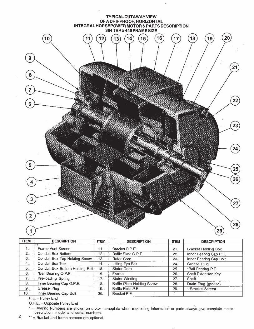

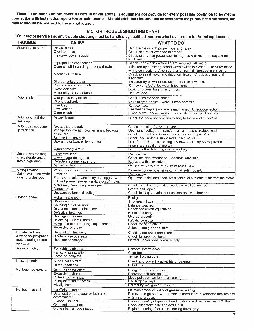

Motor Trouble-Shooting Chart
Caution:1. Disconnect power to the motor before performing service or maintenance.2. Discharge all capacitors before servicing motor.3. Always keep hands and clothing away from moving parts.4. Be sure required safety guards are in place before starting equipment.
Motor fails to start uponinitial installation.
Problem: What To Do:Like Causes:
Motor is miswired. Verify motor is wired correctly.
May be able to reassemble; otherwise, motor should be replaced.Motor damaged and rotor is striking stator.
Replace fan guard.Fan guard bent and contacting fan.
Motor has been running, thenfails to start.
Fuse or circuit breaker tripped. Replace fuse or reset the breaker.
Stator is shorted or went to ground. Motorwill make a humming noise and the circuitbreaker or fuse will trip.
Disassemble motor and inspect windings and internal connections.A blown stator will show a burn mark. Motor must be replaced orthe stator rewound.
Capacitor (on single phase motor) may havefailed.
Inspect to see that the load is free. Verify amp draw of motor versus nameplate rating.
Starting switch has failed.
First discharge capacitor. To check capacitor, set volt-ohm meter toRX100 scale and touch its probes to capacitor terminals. If capacitoris OK, needle will jump to zero ohms, and drift back to high. Steadyzero ohms indicates a short circuit; steady high ohms indicates an open circuit.
Motor runs but dies down. Voltage drop. If voltage is less than 10% of the motor’s rating contact powercompany or check if some other equipment is taking power awayfrom the motor.
Verify the load has not changed. Verify equipment hasn’t got tighter. Iffan application verify the air flow hasn’t changed.
Load increased.
Motor takes too long to accelerate. Defective capacitor Test capacitor per previous instructions.
Faulty stationary switch. Inspect switch contacts and connections. Verify that switch reedshave some spring in them.
Bad bearings. Noisy or rough feeling bearings should be replaced.
Motor runs in the wrong direction. Incorrect wiring.
Make sure that the voltage is within 10% of the motor’s name-plate rating. If not, contact power company or check if some otherequipment is taking power away from the motor.
Motor overload protector continuallytrips.
Load too high.
Rewire motor according to wiring schematic provided.
Motor overloaded or load jammed.
Voltage too low.
Ambient temperature too high.
Protector may be defective.
Winding shorted or grounded.
Disassemble motor and inspect both the centrifugal and stationaryswitches. The weights of the centrifugal switch should move in andout freely. Make sure that the switch is not loose on the shaft.Inspect contacts and connections on the stationary switch.Replace switch if the contacts are burned or pitted.
Verify that the load is not jammed. If motor is a replacement, verify that the rating is the same as the old motor. If previousmotor was a special design, a stock motor may not be able toduplicate the performance. Remove the load from the motor andinspect the amp draw of the motor unloaded. It should be lessthan the full load rating stamped on the nameplate.
Verify that the motor is getting enough air for proper cooling. Mostmotors are designed to run in an ambient temperature of less than40°C. (Note: A properly operating motor may be hot to the touch.)
Replace the motor’s protector with a new one of the same rating.
Inspect stator for defects, or loose or cut wires that may cause itto go to ground.
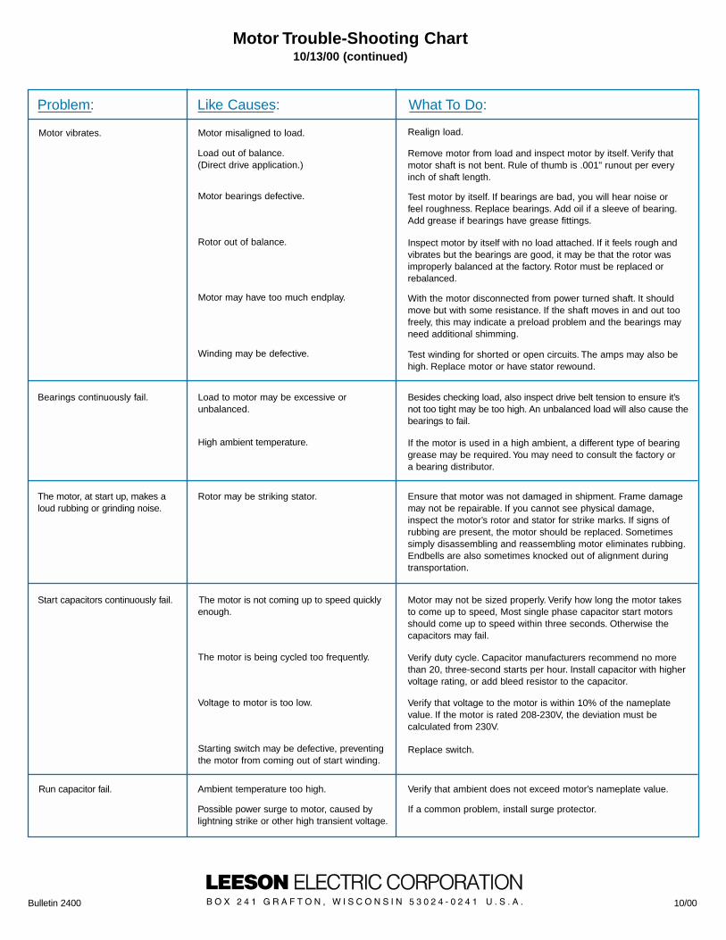
Motor vibrates.
Problem: What To Do:Like Causes:
Motor misaligned to load. Realign load.
Load out of balance.(Direct drive application.)
Remove motor from load and inspect motor by itself. Verify thatmotor shaft is not bent. Rule of thumb is .001" runout per everyinch of shaft length.
Motor bearings defective. Test motor by itself. If bearings are bad, you will hear noise orfeel roughness. Replace bearings. Add oil if a sleeve of bearing.Add grease if bearings have grease fittings.
Rotor out of balance.
Winding may be defective.
Inspect motor by itself with no load attached. If it feels rough andvibrates but the bearings are good, it may be that the rotor wasimproperly balanced at the factory. Rotor must be replaced orrebalanced.
With the motor disconnected from power turned shaft. It shouldmove but with some resistance. If the shaft moves in and out toofreely, this may indicate a preload problem and the bearings mayneed additional shimming.
Test winding for shorted or open circuits. The amps may also behigh. Replace motor or have stator rewound.
Bearings continuously fail. Load to motor may be excessive orunbalanced.
Besides checking load, also inspect drive belt tension to ensure it’snot too tight may be too high. An unbalanced load will also cause thebearings to fail.
High ambient temperature. If the motor is used in a high ambient, a different type of bearinggrease may be required. You may need to consult the factory ora bearing distributor.
The motor, at start up, makes aloud rubbing or grinding noise.
Rotor may be striking stator. Ensure that motor was not damaged in shipment. Frame damagemay not be repairable. If you cannot see physical damage,inspect the motor’s rotor and stator for strike marks. If signs ofrubbing are present, the motor should be replaced. Sometimessimply disassembling and reassembling motor eliminates rubbing.Endbells are also sometimes knocked out of alignment duringtransportation.
Motor may not be sized properly. Verify how long the motor takesto come up to speed, Most single phase capacitor start motorsshould come up to speed within three seconds. Otherwise thecapacitors may fail.
Start capacitors continuously fail. The motor is not coming up to speed quicklyenough.
The motor is being cycled too frequently. Verify duty cycle. Capacitor manufacturers recommend no morethan 20, three-second starts per hour. Install capacitor with highervoltage rating, or add bleed resistor to the capacitor.
Run capacitor fail.
Voltage to motor is too low. Verify that voltage to the motor is within 10% of the nameplatevalue. If the motor is rated 208-230V, the deviation must be calculated from 230V.
Motor Trouble-Shooting Chart10/13/00 (continued)
Motor may have too much endplay.
Starting switch may be defective, preventingthe motor from coming out of start winding.
Replace switch.
Ambient temperature too high.
Possible power surge to motor, caused bylightning strike or other high transient voltage.
Verify that ambient does not exceed motor’s nameplate value.
If a common problem, install surge protector.
Bulletin 2400 10/00

LubricationThis motor is supplied with pre-lubrication ball bearings. No lubrication required before start up.
Relubrication IntervalsThe following intervals are suggested as a guide:
Lubrication
Use high quality ball bearing lubricant. Use consistency of lubricant suitable for class of insulation stamped onnameplate as follows:
Procedure
If motor is equipped with Alemite fitting, clean tip of fitting and apply grease gun. Use 1 to 2 full strokes onmotors in NEMA 215T frame and smaller. Use 2 to 3 strokes on NEMA 254T thru NEMA 365 T frame. Use 3to 4 strokes on NEMA 404T frames and larger. On motors having drain plugs, remove drain plug and operatemotor for 20 minutes before replacing drain plug.
On motors equipped with slotted head grease screw, remove screw and apply grease tube to hole. Insert 2 to3 inch length of grease string into each hole on motors in NEMA 215T frame and smaller. Insert 3 to 5 inchlength on larger motors. For motors having drain plug and operate motor for 20 minutes before replacing drainplug.
CAUTION: Keep lubricant clean. Lubricate motors at standstill. remove and replace drain plugs at standstill. Donot mix petroleum lubricant and silicone lubricant in motor bearings.
Lubrication InstructionsFor Ball Bearing Motors
H.P. RANGESub Fractional to 7 1/2
10 to 4050-200
Sub Fractional to 7 1/210 to 4050 to 200
All
Sub Fractional to 4050 to 200
SUGGESTED RELUBRICATION INTERVALSHOURS OF SERVICE PER YEAR
5,000
Continuous Normal Applications
Season Service MotorIdle 6 Months or More
Continuous High AmbientsDirty or Moist Locations
High VibrationsWhere Shaft End is Hot (Pumps-Fans)
RELUBE INTERVAL5 Years3 Years1 Year2 Years1 Year
9 Months1 Year
(Beginning of Season)6 Months3 Months
300-088.02
CONSISTENCY
Medium
LUBRICATION CONSISTENCYINSULATION
CLASS
B & F
F & H
TYPICALLUBRICATION
Shell Dolium Rand/or
Chevron SR1 2
FRAMETYPE
Sub Fractionalto 447T
All
TYPE
Polyurea

1001212121212121012812612412410282816141404
1501212121210128126124124102828160604002
0002
200121212121012812612412410282616004002
0002
00000
30012121012812610410410281606004
00002
00002
2500
30000
500101281261048281806
0004
0004
00002
3000
3000
50000500000
SINGLE PHASE MOTORS - 230 VOLTS
H.P.
1 1/2235
7 1/2
100
1010866
150
88844
200
88643
300
66421
500
44200
TRANSFORMERKVA
335
7 1/210
DISTANCE - MOTOR TO TRANSF. IN FT.
InstallationAfter unpacking, check for damage. Be sure that shaft rotates freely. Before making electrical power connections,check for proper grounding of motor and application. All electrical contacts and connections must be properlyinsulated and enclosed. Couplings, belts, chains or other mounted devices must be in proper alignment, balanceand secure to insure safe motor operation.
Electrical Wiring
Prior to connecting to the power line, check nameplate for proper voltage and rotation connection. This motorshould be installed in compliance with the National Electrical Code and any other applicable codes. Voltage atmotor not to exceed + or -10% of nameplate. Authorized person should make all electrical connections.
Mounting
This motor should be securely mounted to the application. Sufficient ventilation area should be provided toinsure proper operation.
RECOMMENDED COPPER WIRE & TRANSFORMER SIZE
Installation Maintenance InstructionsAC Induction Motors
VOLTS230460230460230460230460230460230460230460230460230460230460230460230460230460230460
THREE PHASE MOTORS - 230 & 460 VOLTS
H.P.1 1/21 1/2
223355
7 1/27 1/2
101015152020252530304040505060607575
TRANSFORMERKVA
3333557
1/27 1/2
101015152020
ConsultLocalPower
Company
DISTANCE - MOTOR TO TRANSF. IN FT.