Embed Size (px)
Citation preview
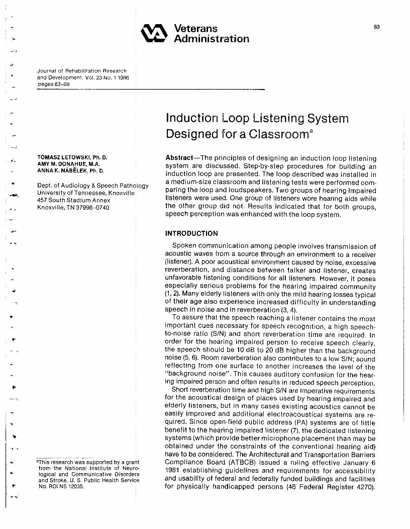
Journal of Rehabilitation Researchand Development, Vol . 23 No . 1 1986pages 63-69
VeteransAdministration
63
`-
TOMASZ LETOWSKI, Ph . D.AMY M. DONAHUE, M .A.ANNA K. NABELEK, Ph . D.
Dept. of Audiology & Speech PathologyUniversity of Tennessee, Knoxville457 South Stadium AnnexKnoxville, TN 37996-0740
aThis research was supported by a grantfrom theNational Institute ofNeuro-logical and Communicative Disordersand Stroke, U . S. Public Health ServiceNo. R01 NS 12035 .
U~~~~~~~^~~~ Loop~~ Listening ~~~~~~~~~~~~^ ^~~~~`~~~~~^ ^
System̂ ~
Designed for ~ a~~ ~~U~~~~~~~~~a~~ .~ .~~~~ . .~°=°
Classroom
Abstra%t--The principles of designing an induction loop listeningsystem are discussed . Step-by-step procedures for building aninduction loop are presented . The loop described was installed ina medium-size classroom and listening tests were performed com-paring the loop and loudspeakers . Two groups of hearing impairedlisteners were used . One group of listeners wore hearing aids whilethe other group did not . Results indicated that for both groupo,speech perception was enhanced with the loop system.
INTRODUCTION
Spoken communication among people involves transmission ofacoustic waves from aaou,oe through an environment to a receiver(listener) . A poor acoustical environment caused by noise, excessivereverberation, and distance between talker and listener, createsunfavorable listening conditions for all listeners. However, it posesespecially serious problems for the hearing impaired community(1, 2) . Many elderly listeners with only the mild hearing losses typicalof their age also experience increased difficulty in understandingspeech in noise and in reverberation (3, 4).
To assure that the speech reaching a listener contains the mostimportant cues necessary for speech recognition, a high speech-to-noise ratio (SIN) and short reverberation time are required . Inorder for the hearing impaired person to receive speech clearly,the speech should be 10 dB to 20 dB higher than the backgroundnoise (5, 6) . Room reverberation also contributes to a low SIN ; soundreflecting from one surface to another increases the level of the"background noise" . This causes auditory confusion for the hear-ing innpeinadporaon endoftenneau!tainneduoedapaeohpencepUon.
Short reverberation time and high SIN are imperative requirementsfor the eoouutioml design of places used by hearing impaired andelderly listeners, but in many cases existing acoustics cannot beeasily improved and additional e!eotroaoouatical systems are re-quired. Since open-field public address (PA) systems are of littlebenefit to the hearing impaired listener (7), the dedicated listeningsystems (which provide better microphone placement than may beobtained under the constraints of the conventional hearing aid)have to be considered . The Architectural and Transportation BarriersCompliance Board (ATBCB) issued a ruling effective January 61981 establishing guidelines and requirements for accessibilityand usability of federal and federally funded buildings and facilitiesfor physically handicapped persons (46 Federal Register 4270) .
64
LETOWSKI et al . : Induction Loop Listening System
The final ATBCB rule stated, in part : "Assemblyareas must be provided with a listening system toassist no fewer than two persons with severe hearingloss." The rule states that acceptable types of lis-tening systems include, but are not limited to, audioloops and radio frequency systems . A buildingdesigned, constructed, altered, or leased after theeffective date of an accessibility standard issuedunder the Architectural Barriers Act (1968) mustcomply with the standard.
There are four basic types of listening systems:( i ) hard-wired systems, (ii) induction loop systems,(iii) radio frequency broadcasting systems, and(iv) infrared-light transmission systems . This paperdiscusses design principles, installation, and per-formance evaluation of an actual induction loopsystem installed in a medium-size classroom . Thisdesign can be replicated easily in places such asauditoriums, small churches and conference roomsrequiring permanent use of a reliable listening sys-tem. The design and construction of an inductionloop system is simple and inexpensive . Basic advan-tages and limitations of such a system are given inTable 1.
SYSTEM DESIGN CALCULATIONS
Induction Loop Principle
The induction loop system consists of a multiturnwire loop (transmitting loop) encircling the area tobe served, with both loop ends connected to theoutput of an audio amplifier into which the programnnetoriml is delivered. The amplifier's output createsa changing electric current passing through theloop, and that, in turn, creates a changing magneticfield in the area within the loop . The changes inthat magnetic field's strength carry, in analog form,the program rnaterial fed into the audio amplifier.
If someone within the circle of the transmittingloop is carrying a small pickup loop, the changingmagnetic field concentrated in that area will inducea similarly changing electric current flow in theGnna\! loop . If the small loop is connected to theinput of a receiving amplifier (or if the small loop isthote!e!oop of a hearing aid with a "T" switch) theelectrical current will produce an acoustic signalwhen it passes through an electroacoustic trans-ducer located at the listener's ear.
An induction loop system can be used either as apermanent installation or as a portable facility forboth individuol and group listening . Another impor-tant feature of this system is that its amplifier canbe used (without any change in the loop installation)as part of a public address system when connected
to a loudspeaker.The dimensions of the loop depend upon the
shape and area of the room to be served.Induction loop systems can work as either direct
audio-frequency, or high-frequency, transmissionsystems. In the latter case, either amplitude modu-lation (AM) or frequency modulation (FM) can be
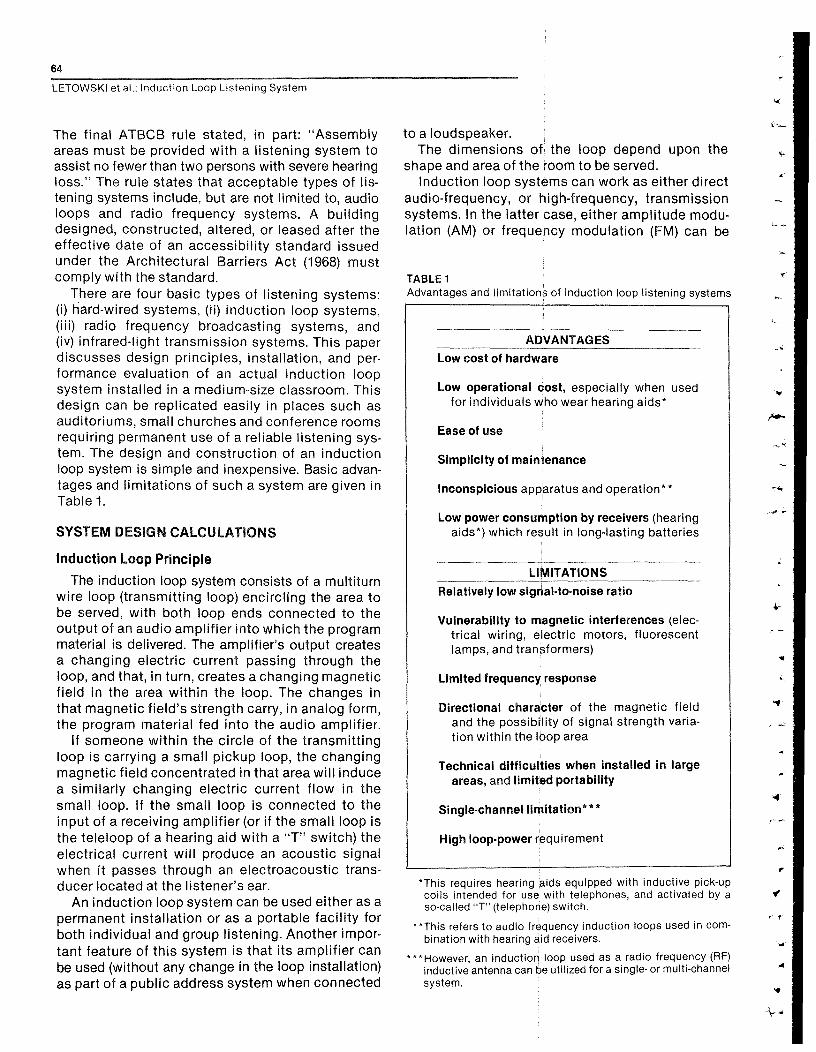
TABLE 1Advantages and limitations of induction loop listening systems
ADVANTAGES
Low cost of hardware
Low operational cost, especially when usedfor individuals who wear hearing aids*
Ease of use
Simplicity of maintenance
Inconspicious apparatus and operation**
Low power consumption by receivers (hearingaids*) which result in long-lasting batteries
LIMITATIONS
Relatively low signal-to-noise ratio
Vulnerability to magnetic interferences (elec-trical
wiring,
electric
motors,
fluorescentlamps, and transformers)
Limited frequency response
Directional character of the magnetic fieldand the possibility of signal strength varia-tion within the loop area
Technical difficulties when installed in largeareas, and limited portability
Single-channel limitation***
High loop-power requirement
*This pick-upcoils intended for use with telephones, and activated by aoo-caxnd^T^(te!ophom) mwivcx.
**This refers to audio frequency induction loops used incom-bination withhaurinOaidmookmm.
***However, an induction loop used aoa radio frequency (RF)inductive antenna can be utilized for a single- or multi-channelsystem .
65
Journal of Rehabilitation Research and Development Vol . 23 No . 1 1986
employed to carry the low frequency audio signals.High frequency induction loop systems, due totheir multichannel capability, are primarily used insimultaneous translation systems . Audio frequencyinduction loop systems are usually employed inschools for hearing impaired children, as attach-ments to home radio and/or television receivers,and in such public places as theaters, cinemas,auditoriums, churches, synagogues, and meetinghalls, for the benefit of anyone experiencing diffi-culties in sound perception . A personal hearing aidused as an audio loop receiver enables the wearerto take advantage of an audio loop signal trans-mission whenever such loops are available, assum-ing that a proper magnetic field strength is provided.
Geometrical Considerations of the Site
The classroom chosen for the installation of theinduction loop system to be described here is rec-tangular in shape. All electrical wiring and outlets,and windows, are on the outer (longer) wall . Theroom has two doors near its corners in the wallopposite the windows. The volume (V) of the roomis 91 .2 m3 (7 .6 x 5 .0 x 2.4 m). The floor of the roomis fully carpeted, the ceiling is tiled with acousticalpanels, and there are three fluorescent light arrayswith axes perpendicular to the windows . Roomwall surface construction consists of painted cinderblocks . Room reverberation time was 0 .35 seconds(average value of octave bands of noise centered at500 Hz, 1000 Hz, and 2000 Hz) measured with thesignal source located on the room axis at 3 m fromthe room center (microphone location) and at about1 m from the adjacent wall . The average level of theambient noise in the classroom was 62 dB (46 dB Aweighting, 32 dB Leg) with occasional peaks reach-ing 72 dB.
The basic design consideration for inductionloop construction is the size and location of the"specified listening area ." That area is not neces-sarily the entire geometric area containing theinduction loop ; it is usually defined as the area ofthe room where the intensity of the magnetic fieldproduced by the loop at 500 Hz does not deviate bymore than 3 dB from a value measured at the centrallistening point . These data refer to the verticalcomponent (Hv) of the magnetic field, since thehorizontal component (H h) is usually ignored in theloop design . This is because : (i) the vertical fieldstrength predominates over most of the loop area,(ii) the telecoils in hearing aids are typically posi-tioned to be most sensitive to the vertical field,and (iii) rotation of the hearing aid about the verticalaxis (as in turning the head) results in no change in
the strength of the pick-up from the vertical Com-ponenLwhereas thepick-up from th*field's hori-zontal component can change from maximum tozero with such rotation.
To obtain the largest possible listening area, theloop was located next to room boundaries encirclingthe floor area S = 38.15 nn 2 . When routing a loop, itis important to avoid any electrical wires in theproximity of the loop, especially where placementwould put the loop and existing wires parallel toeach other . Another basic rule in routing a loop is tomaintain as large a distance as possible betweenany steel elements of the building's structure andthe loop. In the installation described here, it wasnecessary to avoid electrical wiring located in theupper part of the ononn, and metal structure support-ing the ceiling . The solution was to place the loopat the floor level (under the carpet) since it was notprohibited by required listening height (h), i .e . thedistance between the loop plane and the listenerplane.
Listening height has an important effect uponthe uniformity of the magnetic field in the listeningarea. The greater the value of the coefficient Crelat-ing listening height (h) and the size of the listeningarea (S)
C= h
[ 1 ]
the less the variability of magnetic field strengthinside the loop in the listening plane . According toPhilbrick (8) the value of the coefficient C should bebetween 0 .15 and 0.20 to provide the best com-promise between the area of coverage and theacceptable range of variation in magnetic fieldotn*ngth, giving a maximum 4 dB range of verticalfield strength within more than 95 percent of theloop area . In rectangular loops, the minimum listen-ing height also depends slightly on a side ratio . Fora loop with a side ratio of 1 :1 .6. which is the sideratio of the designed loop, the value of coefficientC should be greater than 0.2 to assure that the maxi-mum range of variation in magnetic field is lessthan 4 dB. Thua, according toformula [1], the mini-mum listening height value of the designed loopsystem should fullfill the condition
hmin> C (S/2)'/2
[2]
and
hmin> 0i2 0815Q8a = 0i87m
[3]
Since the above h value secures the proper listeningconditions for both sitting adults and walking/stand-ing children, the loop placement at the floor levelwas ultimately accepted .
66
LeToWSmet al . : Induction Loop Listen ng System
Magnetic Field Intensity
Once the size and location of the loop have beendecided, the required electric current flowing in theloop has to be calculated . The required value of thecurrent is determined by the magnetic field intensityneeded to produce a signal 30dBto40 dB higherthan the level of the ambient noise (5) . The ambientnoise is produced by electromagnetic fields otherthan the loop . The required value of current is alsopartly determined by loop geometry.
The international standards for the magnetic fieldintensity produced by audio induction loop systemscall for the level -20 dB re 1 Alm* at 1000 Hz with aninput signal at a level equal to the long-time averagevalue of the speech signal applied to the input ofthe system (9, 10 ' 11) . This field intensity roughlycorresponds to the volume control setting neededon hearing aids for acoustical reception in typicalenvironments . In other words, when a person listen-ing through a hearing aid switches from the "T"(te!eooi!)to "M" (microphone) mode of reception,the sound of someone speaking normally shouldbe approximately as loud as the sound produced byelectromagnetic transmission from the loop.
On the other hand, the intensity of the magneticfield should not be so high that it could overload ahearing aid or a receiving amplifier . According toIEC recommendations, maximum magnetic fieldintensity should not exceed -8 dB re 1 Alm at 1000Hz (9, 10). This maximum value is derived using thepremise that the ratio of the maximum short-timeaverage level of a speech signal (approx . 0 .125 s) tothe long-time average level is approximately 12 dB(10).
The magnetic ambient noise in the classroomwas measured using the Flux Probe Eagle ModelDL-100. The vertical component of the field wasmuch stronger than any component in the horizontalp!ano, and varied between 0 .001 and 0.002 AJnnthroughout the room . When the frequency com-ponent of 60 Hz was filtered out, the magnetic noise!evel dropped below 0 .0003 and 0 .0006 Alm withlights and air conditioner unit turned off and on,respectively . These results indicate that, for a nomi-nal magnetic field intensity of 0 .1 A/m and with the60'Hz noise component filtered out, the signal-to-noise ratio for electromagnetic transmission exceeds45-50 dB—which assures acceptable listeningconditions.
`AhniaanaUbmwatkmhx^ompem-tumapmmmer,^a moaoumof the combined effect of coil turns, current flow, and distance,in calculating field strength .
Biot and Savart, two French physicists, formulatedthe law for magnetic field intensity (dHv) at a distance(r) from a segment of a conducting wire (cis) carryingcurrent of intensity (I) with a the angle between (s)and (r):
Loop Current Intensity
For a rectangular loop and an observation pointlocated in the listening plane, formula [4] leads tothe equation
4x!xh 1~
+
\
whereloop, h is a listening height, and I is a current inten-sity. Assuming that Hv = 0 .1 Nm, and that h changesbetween 0.9 m and 1 .8 m, which covers variouslistening heights including a standing adult, therequired nominal value of a loop current in the sys-tem is I = 2 .5 A. The short-term maximum currentrequirements call for the value
since the natural peaks of speech can exceed theaverage value by some 12 dB.
Loop Design
The required total cross-sectional area (CSA) ofthe loop conductors can be calculated from theformula
where id =2Ahnnfi an assumed maximum currentdensity in the conductor . Thus,
I max
[8]
A loop wire size and number of loop turns can beconsecutively selected for the wire that will conductthe required current intensity safely and will providea required resistance value (R) matching that of theamplifier. Since
and
where CSA is the total cross-sectional area of theloop conductors, F is the cross-sectional area of asingle loop wire, n is the number of loop turns, p isloop perimeter, and is resistivity of the loop wire (C= 0.025 for metal compound used typically in elec-
[4]
[7]=CGAxid!
~-
67
Journal of Rehabilitation Research and Development Vol . 23 No . 11S88
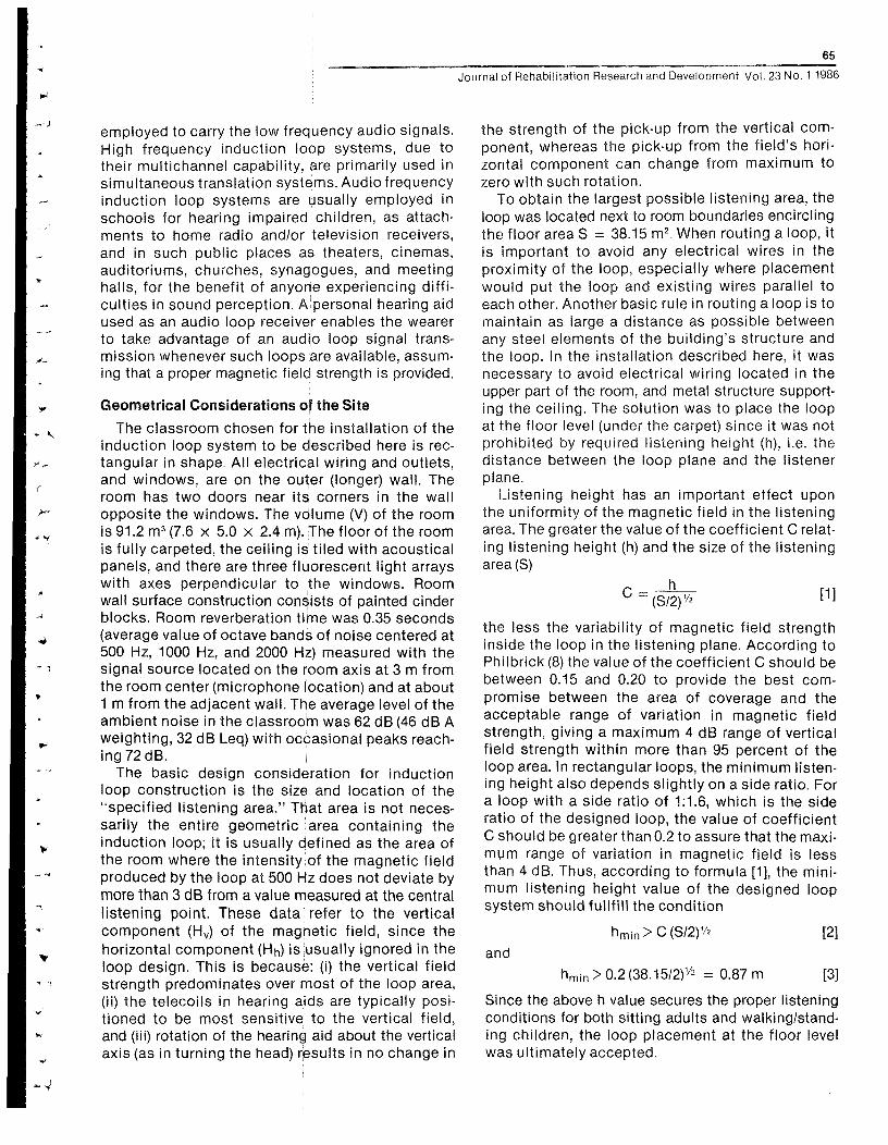
FIGURE 1Schematic of loop wiring.Symbols tl-t8 indicate loopturn number, and numbersfrom 1 to 16 indicate the be-ginning (odd number) and theend (even number) of a turn.
troacoustical wiring), then
[11]
For the values determined above, formula [11] givesa value for n of 7 .3, leading to eight as the numberof loop turns required . The cross-sectional area ofthe individual wires should exceed 0 .625 mnn 2 .
To comply with the above requirements, we havechosen Beldon 9A22016 flat cable consisting of 16wires, each of 0 .76 mm diameter (22 gauge) . By usingtwo wires in parallel per turn (16 wires connected in8 pairs) we have met our cross-sectional area require-ments. The schematic of the wire connections isgiven in Figure 1, where solid lines indicate perma-nent connections and broken lines indicate theconnections to be made with plugs and sockets.The arrangement allows for loop configurations tomatch other resistance values or/and other magneticfield requirements, if needed.
Frequency Response
The loop circuit has both resistive and inductivecharacter (RL circuit) . The loop impedance valueincreases with the signal frequency, resulting in alowering Of the current intensity and of the magneticfield intensity at higher frequencies . The upper limit-ing frequency fu L (3 dB signal loss) for an RL circuitformed by the loop can be calculated from theformula
fU
[12]
where L is loop inductance . In the case ofthnrect-angular !oop ' \nductanoeLcanbeoa!ou!atedfnomn
the formula given by DaIsgaard (12)
L = 0.092 (Sy/2 n x [Gf !og(S/F)] 10' 6[13]
where F is wire cross-sectional area and S is thearea encircled by the loop . The inductance value forthe loop in question is 275 IAH . Thus, accordingto equation [12], upper limiting frequency uL willbe in the range between 4500 Hz and50OOHz.
Power Requirements
Fora loop with resistance (R), the output power(P) supplied by the power amplifier may be deter-mined by the expression
P = R P
[14]
Assuming that nominal current intensity does notexceed 2 .5 A and that loop resistance equals 8 ohms,the nominal power required from the power amplifierwould be 50 W. However, to secure undistortedpeak eignal intensities which require up to 10 A ofcurrent, the short-term power rating should allow800 W.
PERFORMANCE TESTING
System Arrangement and Adjustment
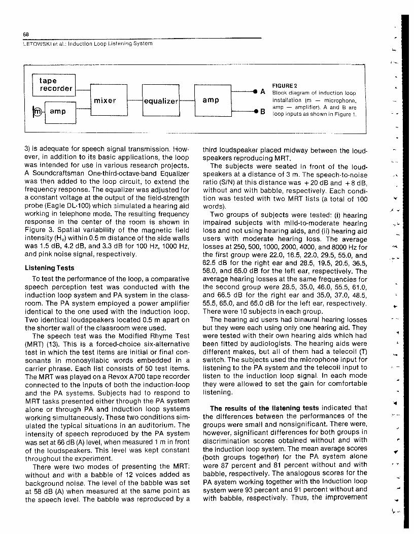
The block diagram of the induction loop installa-tion is presented in Figure 2 . A McIntosh 40 PowerAmplifier, rated at 200 W/8 ohms, was used to pro-vide power to the loop . Initial tests with varioushearing aids (Phonic Ear, Siemens, andVVidex)con-firmed theaetiefectorypovveroapaoityofthe loop.
The frequency response of the loop system (Figure
68
LETOWSKI et al . : Induction Loop Listening System
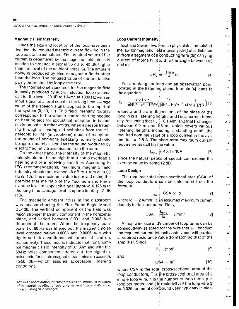
ampmixer equalizer
taperecorder
la amp
FIGURE2A Block diagram of induction loop
installation (m — microphone,amp — amplifier) . A and B areloop inputs as shown in Figure 1.
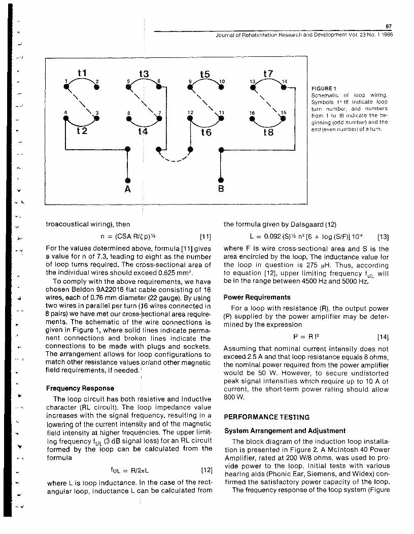
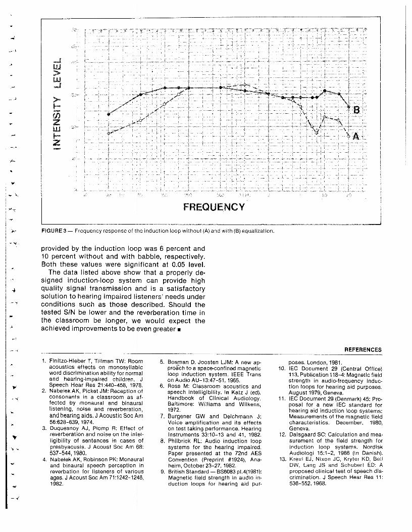
3) is adequate for speech signal transmission . How-ever, in addition to its basic applications, the loopwas intended for use in various research projects.A Soundcraftsman One-third-octave-band Equalizerwas then added to the loop circuit, to extend thefrequency response . The equalizer was adjusted fora constant voltage at the output of the field-strengthprobe (Eagle DL-100) which simulated a hearing aidworking in telephone mode. The resulting frequencyresponse in the center of the room is shown inFigure 3 . Spatial variability of the magnetic fieldintensity (H V) within 0 .5 m distance of the side wallswas 1 .5 dB, 4.2 dB, and 3 .3 dB for 100 Hz, 1000 Hz,and pink noise signal, respectively.
Listening Tests
To test the performance of the loop, a comparativespeech perception test was conducted with theinduction loop system and PA system in the class-room . The PA system employed a power amplifieridentical to the one used with the induction loop.Two identical loudspeakers located 0 .5 m apart onthe shorter wall of the classroom were used.
The speech test was the Modified Rhyme Test(MRT) (13) . This is a forced-choice six-alternativetest in which the test items are initial or final con-sonants in monosyllabic words embedded in acarrier phrase. Each list consists of 50 test items.The MRT was played on a Revox A700 tape recorderconnected to the inputs of both the induction-loopand the PA systems. Subjects had to respond toMRT tasks presented either through the PA systemalone or through PA and induction loop systemsworking simultaneously. These two conditions sim-ulated the typical situations in an auditorium . Theintensity of speech reproduced by the PA systemwas set at 66 dB (A) level, when measured 1 m in frontof the loudspeakers . This level was kept constantthroughout the experiment.
There were two modes of presenting the MRT:without and with a babble of 12 voices added asbackground noise . The level of the babble was setat 58 dB (A) when measured at the same point asthe speech level . The babble was reproduced by a
third loudspeaker placed midway between the loud-speakers reproducing MRT.
The subjects were seated in front of the loud-speakers at a distance of 3 m. The speech-to-noiseratio (S/N) at this distance was +20 dB and +8 dB,without and with babble, respectively . Each condi-tion was tested with two MRT lists (a total of 100words).
Two groups of subjects were tested : (i) hearingimpaired subjects with mild-to-moderate hearingloss and not using hearing aids, and (ii) hearing aidusers with moderate hearing loss . The averagelosses at 250, 500, 1000, 2000, 4000, and 8000 Hz forthe first group were 22 .0, 16 .5, 22 .0, 29 .5, 55 .0, and62.5 dB for the right ear and 28 .5, 19 .5, 20 .5, 36 .5,58.0, and 65.0 dB for the left ear, respectively . Theaverage hearing losses at the same frequencies forthe second group were 28 .5, 35 .0, 46 .0, 55 .5, 61 .0,and 66.5 dB for the right ear and 35 .0, 37 .0, 48 .5,55 .5, 65 .0, and 65.0 dB for the left ear, respectively.There were 10 subjects in each group.
The hearing aid users had binaural hearing lossesbut they were each using only one hearing aid . Theywere tested with their own hearing aids which hadbeen fitted by audiologists . The hearing aids weredifferent makes, but all of them had a telecoil (T)switch. The subjects used the microphone input forlistening to the PA system and the telecoil input tolisten to the induction loop signal . In each modethey were allowed to set the gain for comfortablelistening.
The results of the listening tests indicated thatthe differences between the performances of thegroups were small and nonsignificant . There were,however, significant differences for both groups indiscrimination scores obtained without and withthe induction loop system . The mean average scores(both groups together) for the PA system alonewere 87 percent and 81 percent without and withbabble, respectively . The analogous scores for thePA system working together with the induction loopsystem were 93 percent and 91 percent without andwith babble, respectively . Thus, the improvement
4-
4
F QU ° :N Y
FIGURE 3 — Frequency response of the induction loop without (A) and with (B) equalization.
provided by the induction loop was 6 percent and10 percent without and with babble, respectively.Both these values were significant at 0 .05 level.
The data listed above show that a properly de-signed induction-loop system can provide highquality signal transmission and is a satisfactorysolution to hearing impaired listeners' needs underconditions such as those described. Should thetested SIN be lower and the reverberation time inthe classroom be longer, we would expect theachieved improvements to be even greater n
REFERENCES
1. Finitzo-Hieber T, Tillman TW : Roomacoustics effects on monosyllabicword discrimination ability for normaland hearing-impaired children . JSpeech Hear Res 21 :440-458, 1978.
2. Nabelek AK, Picket JM : Reception ofconsonants in a classroom as af-fected by monaural and binaurallistening, noise and reverberation,and hearing aids . J Acoustic Soc Am56 :628-639, 1974.
3. Duquesnoy AJ, Plomp R : Effect ofreverberation and noise on the intel-ligibility of sentences in cases ofpresbyacusis . J Acoust Soc Am 68:537-544, 1980.
4. Nabelek AK, Robinson PK: Monauraland binaural speech perception inreverbation for listeners of variousages . J Acoust Soc Am 71 :1242-1248,1982 .
5. Bosman D, Joosten LJM : A new ap-proach to a space-confined magneticloop induction system . IEEE Transon Audio AU-13 :47-51, 1965.
6. Ross M: Classroom acoustics andspeech intelligibility . In Katz J (ed),Handbook of Clinical Audiology.Baltimore: Williams and Wilkens,1972.
7. Burgener GW and Deichmann J:Voice amplification and its effectson test taking performance. HearingInstruments 33 :10-13 and 41, 1982.
8. Philbrick RL: Audio induction loopsystems for the hearing impaired.Paper presented at the 72nd AESConvention (Preprint #1924), Ana-heim, October 23-27, 1982.
9. British Standard — BS6083 pt .4(1981):Magnetic field strength in audio in-duction loops for hearing aid pur-
poses . London, 1981.10. IEC Document 29 (Central Office)
113, Publication 118-4 : Magnetic fieldstrength in audio-frequency induc-tion loops for hearing aid purposes.August 1979, Geneva.
11. IEC Document 29 (Denmark) 45 : Pro-posal for a new IEC standard forhearing aid induction loop systems:Measurements of the magnetic fieldcharacteristics . December, 1980,Geneva.
12. Dalsgaard SC : Calculation and mea-surement of the field strength forinduction loop systems. NordiskAudiologi 15 :1-2, 1966 (in Danish).
13. Kreul EJ, Nixon JC, Kryter KD, BellDW, Lang JS and Schubert ED: Aproposed clinical test of speech dis-crimination . J Speech Hear Res 11:536-552, 1968.
4
_y