Embed Size (px)
DESCRIPTION
Heater4
Citation preview
Power Supply: Voltage double and regulated source
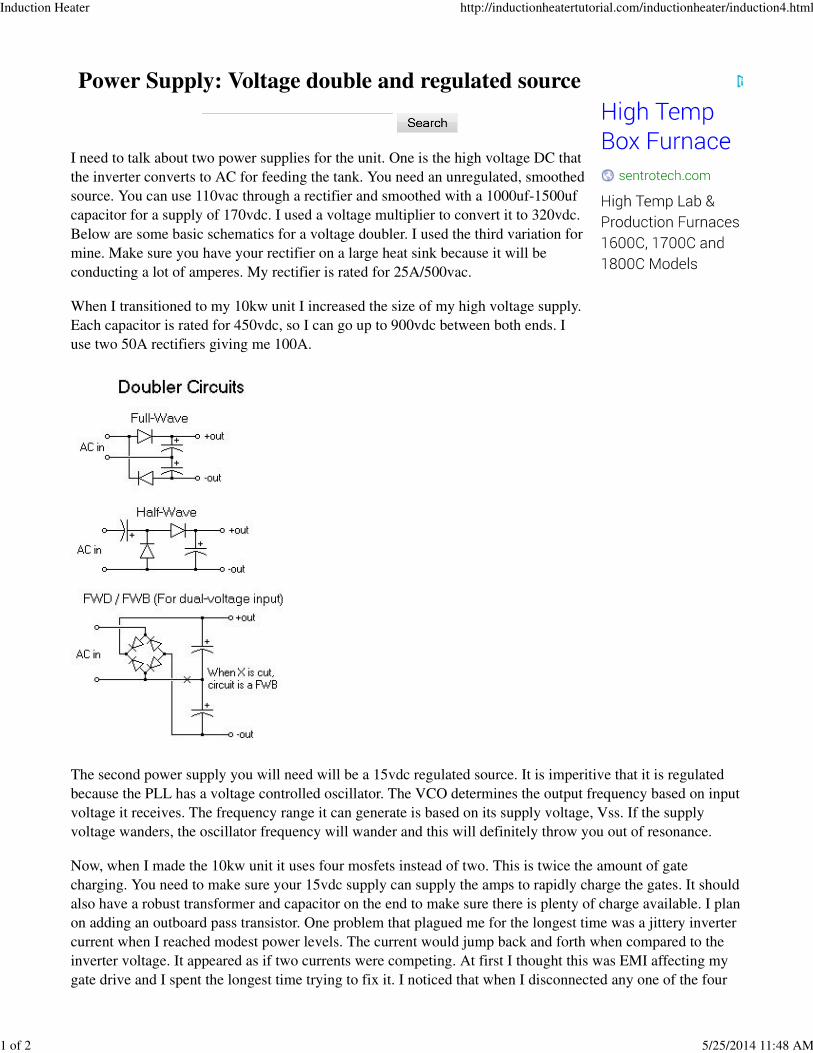
I need to talk about two power supplies for the unit. One is the high voltage DC that
the inverter converts to AC for feeding the tank. You need an unregulated, smoothed
source. You can use 110vac through a rectifier and smoothed with a 1000uf-1500uf
capacitor for a supply of 170vdc. I used a voltage multiplier to convert it to 320vdc.
Below are some basic schematics for a voltage doubler. I used the third variation for
mine. Make sure you have your rectifier on a large heat sink because it will be
conducting a lot of amperes. My rectifier is rated for 25A/500vac.
When I transitioned to my 10kw unit I increased the size of my high voltage supply.
Each capacitor is rated for 450vdc, so I can go up to 900vdc between both ends. I
use two 50A rectifiers giving me 100A.
The second power supply you will need will be a 15vdc regulated source. It is imperitive that it is regulated
because the PLL has a voltage controlled oscillator. The VCO determines the output frequency based on input
voltage it receives. The frequency range it can generate is based on its supply voltage, Vss. If the supply
voltage wanders, the oscillator frequency will wander and this will definitely throw you out of resonance.
Now, when I made the 10kw unit it uses four mosfets instead of two. This is twice the amount of gate
charging. You need to make sure your 15vdc supply can supply the amps to rapidly charge the gates. It should
also have a robust transformer and capacitor on the end to make sure there is plenty of charge available. I plan
on adding an outboard pass transistor. One problem that plagued me for the longest time was a jittery inverter
current when I reached modest power levels. The current would jump back and forth when compared to the
inverter voltage. It appeared as if two currents were competing. At first I thought this was EMI affecting my
gate drive and I spent the longest time trying to fix it. I noticed that when I disconnected any one of the four
Induction Heater http://inductionheatertutorial.com/inductionheater/induction4.html
1 of 2 5/25/2014 11:48 AM
mosfets the current tracing was perfect. This led me to believe that I was falling short on charging all the gates
rapidly enough, and the mosfets were not all conducting identically. Remember, you need to fully turn the
mosfets on in the shortest time possible. I put a scope on the gates and noticed that the slopes changed when I
added the fourth gate. I solved the problem by adding a 39000uf capacitor to my power supply. This was with
a 1.6A transformer and a 2A 15v regulator. The tracing was perfect. I plan on changing the transformer to 3A
and adding adding the outboard pass transistor just to play it safe.
Next Page
Induction Heater http://inductionheatertutorial.com/inductionheater/induction4.html
2 of 2 5/25/2014 11:48 AM