Embed Size (px)
Citation preview
Abstract—The accurate determination of permanent magnet
synchronous machine (PMSM) inductances has been the subject
of much research over a long time. For these reason, this paper
present the calculation of the direct and quadrature inductances
of permanent magnet synchronous machine by the finite element
method (FEM), where the calculation of these parameters is
based on the air gap magnetic field distribution which is the
basis of the analysis of performance electric machines. The
numerical results are presented by diagrams, they discussed and
compared by the experimental once, they show a very good
agreement. This confirms the validity and effectiveness of the
finite element method in solving of these problems
Index Terms—Finite element, inductance direct and
quadrature, magnetic flux density, permanent magnet
synchronous machine.
I. INTRODUCTION
Permanent magnet synchronous motors (PMSM) are
widely used in high-performance drives such as industrial
robots and machine tools for their advantages on high power
density, high-torque, free maintenance and so on. In recent
years, the magnetic and thermal capabilities of the PM have
been considerably increased by employing the high-coercive
PM materials [1]. In last few years, permanent magnet
synchronous motor (PMSM) consequently is acquired in
more and more far-ranging application, because of its
properties such as small volume, light weight, high efficiency,
small inertia, rotor without heat problem, etc. [2]. It is very
important matter to calculate as accurate as possible the
values of the parameters of the PMSM. Of the most important
significance are the direct- and the quadrature- axis
inductances, as they are determining corresponding
synchronous reactances [3]; it is well known that they are the
most significant parameters when dealing with steady state
and/or dynamic performance analysis of PMSM. . Nowadays,
permanent magnet synchronous motor is designed not only to
be more powerful but also with lower mass and lower moment
of inertia. We must into account the required accurate of the
results also the reliability of testing procedures for
determination of the machine parameters, when we develop
permanent magnet synchronous motor model. The
conventional methods of testing for determination of
synchronous machine parameters cannot be applied in the
case of permanent magnet machine. The only alternative to
solve this problem is to use numerical methods [4]-[6].
Manuscript received November 10, 2013; revised March 13, 2014.
The authors are with the Electrical Engineering Department, Badji
Mokhtar University, P. O. Box12, 23000 Annaba, Algeria (e-mail:
bellal.zaghdoud@ gmail.com, [email protected]).
During the last two decades the finite element method proved
to be the most appropriate numerical method in terms of
modeling, flexibility and accuracy to solve the nonlinear
Poisson’s equation governing the magnetic field who's
concerned a principal element in calculation of machine
parameters [5], [6]. Currently, several modeling of electrical
machines softwares are available. The finite element package
FEMM 4.2 (Finite Element Method Magnetic) developed by
D. Meeker available for free on its website was used for the
modeling of the PMSM.
II. RESOLUTION OF THE MAGNETIC FIELD PROBLEM WITH
FEM
The finite element method is a numerical procedure
designed to obtain an approximate solution to a variety of
field problems governed by differential equations. The
solution domain is replaced by the problem of the subdomains
of simple geometric shapes, called elements, in order to
reconstruct the original domain by their assembly. The
unknown variables of the considered field are then expressed
by an approximate function called interpolation function [7],
[8]. These functions are defined on each element using the
values that the variable takes from the field on each node.
Therefore the knowledge of nodal values and interpolation
functions allow defining completely the behavior of the
variable field on each element. Once the nodal variables,
which are actually the unknown factors of the problem, are
calculated, the values of the variables of the field on any point
of the field can also be determined using interpolation
function. The precision of the method depends not only on the
dimensions of elements and their number but also the type of
the interpolation function. As for the numerical method, the
finite element method converges to the exact solution
provided to increase the number of subdivisions of the
solution domain and to ensure continuity of the interpolation
function of its first derivatives along the borders of adjacent
elements [5], [7].
The main steps for implementation of the finite element
method [9] are described below.
A. Pre-Processing
After the problem geometry is defined we have to complete
the entire domain of the electric machine by defining the
material properties and boundary conditions. By imposing the
vector potential zero at the outside diameter of the machine
the magnetic field will be confined to the solution domain,
while the periodicity conditions 𝐴(0) = 𝐴(𝜋) can restrict the
solution domain to a double pole pitch. The basic idea of
FEM application is to divide that complex domain into
Inductances Calculation of Permanent Magnet
Synchronous Machine
Bellal Zaghdoud and Abdallah Saadoun
International Journal of Computer and Electrical Engineering, Vol. 6, No. 3, June 2014
267DOI: 10.7763/IJCEE.2014.V6.836
elements small enough, under assumption to have linear
characteristics and constant parameters. Usually, triangular
elements are widely accepted shapes for 2D FE models. After
this step is completed, the output is always generation of finite
element mesh. It is recommended to make mesh refinements
in the regions carrying the interfaces of different materials, or
with expected or presumed significant changes in the
magnetic field distribution.
B. Processing
In order processing part to be executed and output results to
be obtained system of Maxwell’s equation should be solved.
Using the post-processor software, various results can
viewed as the mapping of field lines and the intensity of the
magnetic induction in different parts of the machine as shown
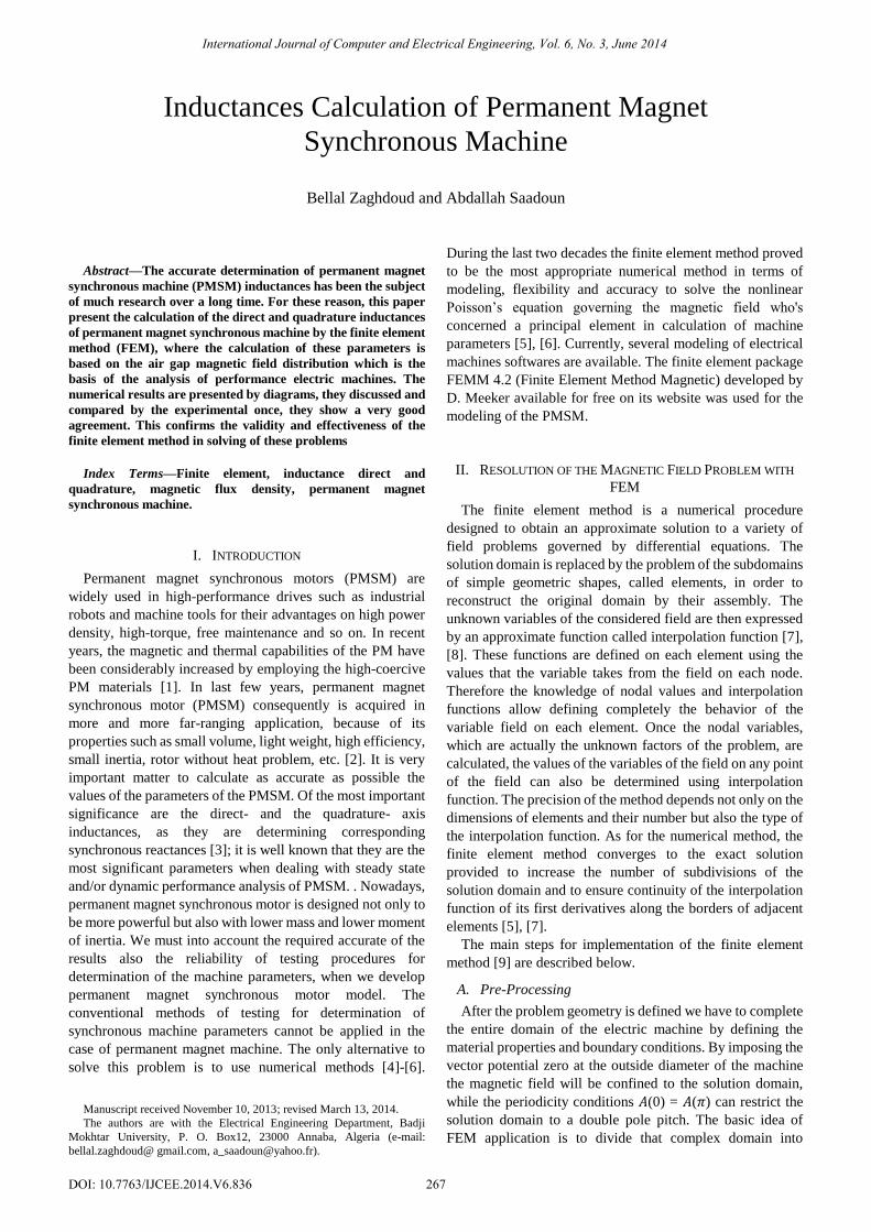
in Fig. 1, however the main result of the simulation is the field
distribution in the air gap which is given either in graphical
form as shown in Fig. 2 or in the form of a table that provides
the magnetic induction at a point as a function of the air gap of
its curvilinear abscissa.
Fig. 1. Magnetic flux distribution in part of the machine.
0 50 100 150 200 250 300-1
-0,8
-0,6
-0,4
-0,2
0
0,2
0,4
0,6
0,8
1
Length, mm
B.n
, Te
sla
Fig. 2. Magnetic field distribution along the air gap.
Examination of these curves shows that rapid variations of
the magnetic field are mainly due to the presence of teeth and
slots of the stator area. Such variations are predictable
because the calculation of the field using an interpolation
function of the first order results in the constancy of the field
[4], [8] at each element of mesh. Moreover, the finite element
solution is incomplete because the model is unable to take into
account electromagnetic phenomena accompanying the
rotation of the rotor. Indeed, in a real machine, the effect of
oscillation of the field between the slots and teeth with
induced eddy currents in the inner surfaces of the teeth,
resulting in a local saturation of the interface zone air gap
magnetic circuit [8]. For these reasons the field variations in a
real machine are less pronounced.
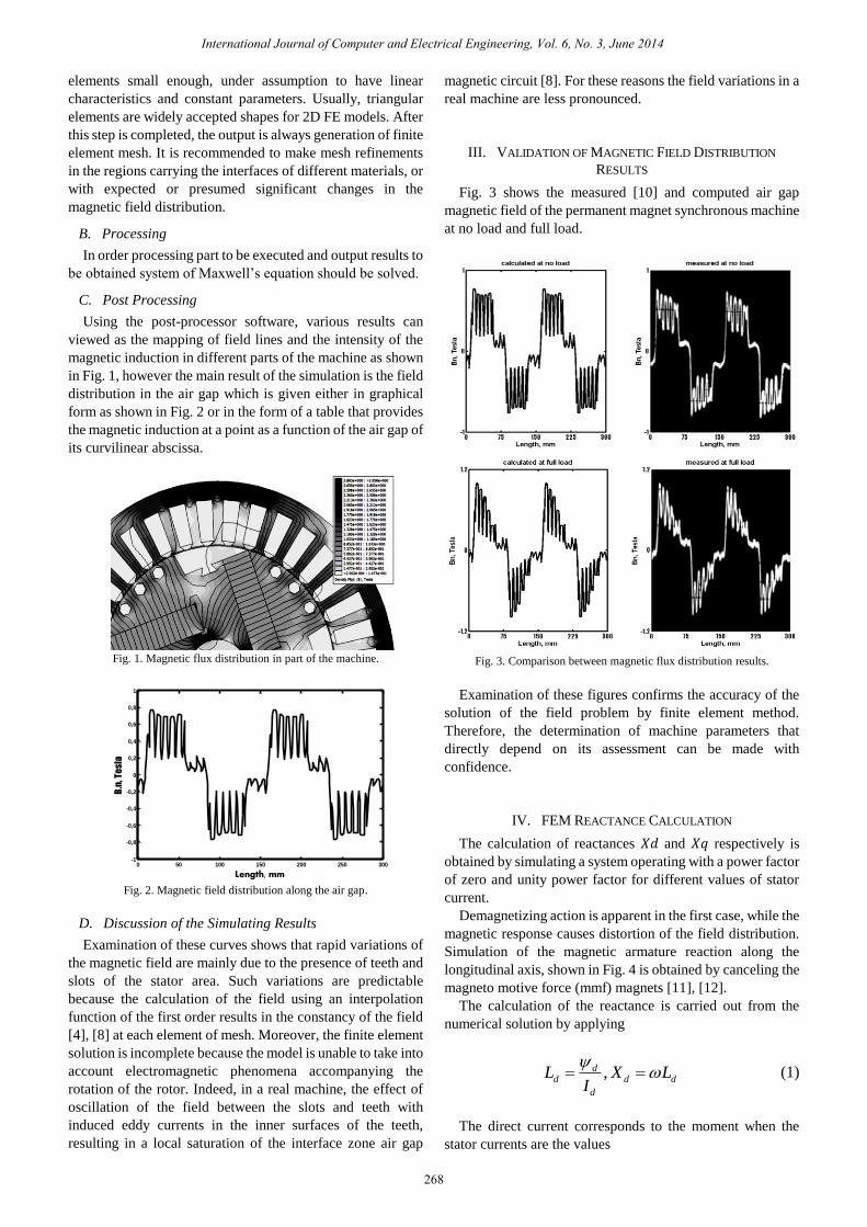
III. VALIDATION OF MAGNETIC FIELD DISTRIBUTION
RESULTS
Fig. 3 shows the measured [10] and computed air gap
magnetic field of the permanent magnet synchronous machine
at no load and full load.
Fig. 3. Comparison between magnetic flux distribution results.
Examination of these figures confirms the accuracy of the
solution of the field problem by finite element method.
Therefore, the determination of machine parameters that
directly depend on its assessment can be made with
confidence.
IV. FEM REACTANCE CALCULATION
The calculation of reactances 𝑋𝑑 and 𝑋𝑞 respectively is
obtained by simulating a system operating with a power factor
of zero and unity power factor for different values of stator
current.
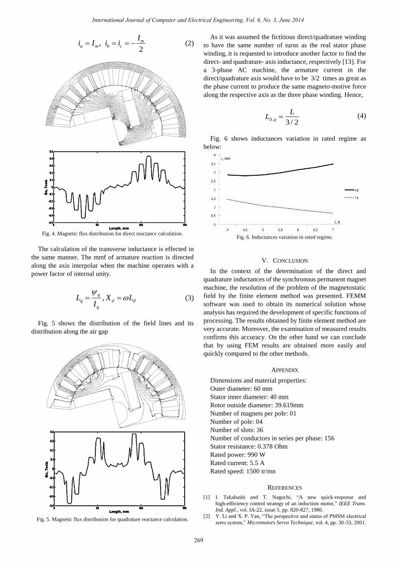
Demagnetizing action is apparent in the first case, while the
magnetic response causes distortion of the field distribution.
Simulation of the magnetic armature reaction along the
longitudinal axis, shown in Fig. 4 is obtained by canceling the
magneto motive force (mmf) magnets [11], [12].
The calculation of the reactance is carried out from the
numerical solution by applying
,dd d d
d
L X LI
(1)
The direct current corresponds to the moment when the
stator currents are the values
International Journal of Computer and Electrical Engineering, Vol. 6, No. 3, June 2014
268
C. Post Processing
D. Discussion of the Simulating Results
,2
ma m b c
Ii I i i (2)
Fig. 4. Magnetic flux distribution for direct reactance calculation.
The calculation of the transverse inductance is effected in
the same manner. The mmf of armature reaction is directed
along the axis interpolar when the machine operates with a
power factor of internal unity.
,q
q d d
q
L X LI
(3)
Fig. 5 shows the distribution of the field lines and its
distribution along the air gap
Fig. 5. Magnetic flux distribution for quadrature reactance calculation.
As it was assumed the fictitious direct/quadrature winding
to have the same number of turns as the real stator phase
winding, it is requested to introduce another factor to find the
direct- and quadrature- axis inductance, respectively [13]. For
a 3-phase AC machine, the armature current in the
direct/quadrature axis would have to be 3/2 times as great as
the phase current to produce the same magneto-motive force
along the respective axis as the three phase winding. Hence,
,3 / 2
d q
LL (4)
Fig. 6 shows inductances variation in rated regime as
below:
Fig. 6. Inductances variation in rated regime.
V. CONCLUSION
In the context of the determination of the direct and
quadrature inductances of the synchronous permanent magnet
machine, the resolution of the problem of the magnetostatic
field by the finite element method was presented. FEMM
software was used to obtain its numerical solution whose
analysis has required the development of specific functions of
processing. The results obtained by finite element method are
very accurate. Moreover, the examination of measured results
confirms this accuracy. On the other hand we can conclude
that by using FEM results are obtained more easily and
quickly compared to the other methods.
APPENDIX
Dimensions and material properties:
Outer diameter: 60 mm
Stator inner diameter: 40 mm
Rotor outside diameter: 39.619mm
Number of magnets per pole: 01
Number of pole: 04
Number of slots: 36
Number of conductors in series per phase: 156
Stator resistance: 0.378 Ohm
Rated power: 990 W
Rated current: 5.5 A
Rated speed: 1500 tr/mn
REFERENCES
[1] I. Takahashi and T. Naguchi, “A new quick-response and
high-efficiency control strategy of an induction motor,” IEEE Trans.
Ind. Appl., vol. IA-22, issue 5, pp. 820-827, 1986.
[2] Y. Li and X. P. Yan, “The perspective and status of PMSM electrical
serro system,” Micromotors Servo Technique, vol. 4, pp. 30-33, 2001.
International Journal of Computer and Electrical Engineering, Vol. 6, No. 3, June 2014
269
[3] M. Hadef, M. R. Mekideche, A. Djerdir, and A. Miraoui, “An inverse
problem approach for parameter estimation of interior permanent
magnet synchronous motors,” Progress in Electromagnetics Research
B, vol. 31, no. 15, 2011.
[4] P. Silvester, “Finite elements for electrical engineers,” Cambridge
University Press, 1990,
[5] P. Silvester and M. V. K. Chari, “Finite element solution of saturable
magnetic field problem,” IEEE Trans. on Power Apparatus and
Systems, PAS-89, vol. 7, pp 1642-1651, 1970.
[6] G. O. Young, “Synthetic structure of industrial plastics,” in Plastics,
2nd ed. J. Peters, Ed. New York: McGraw-Hill, vol. 3, pp. 15-64, 1964.
[7] K. J. Binns, C. P. Riley, and T. M. Wong, “The efficient evaluation of
torque and field gradient in permanent magnet with small air gap,”
IEEE Transactions on Magnetics, vol. 21, no. 6, pp 2435-2438, Nov.
1985.
[8] M. Kostenko and L. Piotroski, Electric Machines: Alternating Current
Machines, Moscow: Mir Publishers, vol. 2, 1963.
[9] D. Meeker, “Finite Element Magnetics,” User Manual for FEMM Ver.
4.2, Boston, Massachusets, USA, 2009.
[10] A. Saadoun, “The analysis of the performance of a permanent magnet
synchronous generator,” M.Sc Thesis, University of Liverpool, Aug.
1989.
[11] D. Ban. Zarko, and R. Klaric, “Finite element approach to calculation
of parameters of an interior permanent magnet motor,” Automatika, vol.
46, pp. 113-122, 2005.
[12] K. M. Rahman and S. Hiti, “Identification of machine parameters of a
synchronous motor,” IEEE Trans. Ind. Appl., vol. 41, no. 2, pp.
557–565, Mar.–Apr. 2005.
[13] L. Chedot, G. Friedrich, and A. Cross, “Saturation model for interior
permanent magnet synchronous machine application to a
starter-generator,” in Proc. 39th IAS Annual Meeting, Seattle, USA,
3–7 Oct. 2004, vol. 1, p. 70.
Bella Zaghdoud was born in Annaba, Algeria. He
received the BS and MS degrees in Institute of
Electrical Engineering from University of Badji
Mokhtar Annaba, Algeria, 2007 and 2009,
respectively. He is currently a PhD student at
Electrical Engineering Department, University of
Annaba, Algeria. His research interests include
electrical machines: modeling, parameters
calculation and control, power converters.
Abdallah Saadoun received his MSc from
University of Liverpool, UK in 1989. He got his DC
degree in 2007 from university of Badji Mokhtar,
Annaba. Currently he is an associate professor in the
Institute of Electrical Engineering and he is a member
of the FP Laboratory at University of Annaba. His
research interests are on power electronics, power
converters, design of electrical machines and control.
International Journal of Computer and Electrical Engineering, Vol. 6, No. 3, June 2014
270