Embed Size (px)
Citation preview
Induced-Drag Minimization of Nonplanar GeometriesBased on the Euler Equations
Jason E. Hicken! and David W. Zingg†
University of Toronto, Toronto, Ontario M3H 5T6, Canada
DOI: 10.2514/1.J050379
The induced drag of several nonplanar con!gurations is minimized using an aerodynamic shape optimizationalgorithm based on the Euler equations. The algorithm is !rst validated using twist optimization to recover anelliptical lift distribution. Planform optimization reveals that an elliptical planform is not optimal when side-edgeseparation is present. Optimized winglet and box-wing geometries are found to have span ef!ciencies that agree wellwith lifting-line analysis, provided the bound constraints on the entire geometry are accounted for in the linearanalyses. For the same spanwise and vertical bound constraints, a nonplanar split-tip geometry outperforms both thewinglet and box-wing geometries, because it canmore easilymaximize the vertical extent at the tip. The performanceof all the optimized geometries is veri!ed using re!ned grids consisting of 88–152 million nodes.
Nomenclatureb = wing spanCD = coef!cient of dragCD;ellip = CD for an elliptical lift distributionCL = coef!cient of liftc = sectional chord lengthcd = sectional drag lengthcl = sectional lift coef!cientD = drage = span ef!ciencyL = liftM = Mach numberq1 = freestream dynamic pressureS = reference areaU1 = freestream velocity magnitude! = angle of attack with respect to the root chord! = circulation distribution" = aspect ratio"1 = freestream density
I. Introduction
F UEL-SUPPLY uncertainty and climate-change mitigation de-mand action from all transportation sectors. Addressing these
challenges will likely require multiple strategies, including ef!-ciency improvements. To this end, drag reduction remains a criticalarea of research for the aviation industry.
Induced drag, also called vortex drag, is an inviscid form of dragexperienced by lifting wings of !nite span. It is the result of workdone on the "uid to sustain the kinetic energy in the trailing vorticalwake. Induced drag represents approximately 40% of the total dragon a conventional aircraft in cruise "ight [1], so concepts that reducevortex drag are certainly worth studying. This is the motivation
behind the present study of nonplanar con!gurations and theiroptimal design.
Roughly speaking, nonplanar con!gurations are geometries thatproduce wakes with vertical structure. Munk [2] established anumber of fundamental results concerning such nonplanar con!g-urations. Among his contributions, Munk showed that nonplanarcon!gurations can have signi!cantly lower induced drag relative toplanar wings with the same span and lift. The example given byMunk is an optimally loaded circular ring-wing, which has half theinduced drag of an optimally loaded planar wing. In the decadesfollowing Munk’s work, nonplanarity has been the subject ofnumerous studies. Wemention a few notable examples here, primar-ily analytical and numerical results. For a more complete reviewsee [1].
Induced-drag theory for nonplanar con!gurations was extendedby Cone [3] to include general circulation distributions. Cone alsoconsidered the induced drag on a number of optimally loaded con!g-urations. In particular, he showed that the elliptical distribution isoptimal for families of closed elliptical loops, including the line andcircle as limiting cases.
Mangler’s [4] analysis of end-plate con!gurations presaged laterwork on winglets. His results were re!ned and generalized byLundry and Lissaman [5], who presented a method to accuratelyevaluate the induced drag of nonplanar con!gurations consisting ofline segments. The induced drag analysis of wing-tip geometries wasfurther generalized by Lowson [6]. He represented winglets aspolynomial curves and superelliptic functions. While the verticalend-plate is optimal, Lowson found that superelliptical functions ofmodest degree can achieve near-optimal induced drags.
Van Dam [7] studied planar geometries that produce nonplanarwakes at angle of attack. While his initial results were shown to beoverly optimistic due to numerical errors [8], the idea of exploitingplanform shape has merit. This is supported by Smith’s work with aplanar split-tip con!guration [9], which was shown to reduce theinduced drag by 6% according to linear theory.More impressive still,a nonlinear analysis using wake relaxation showed a 10% reductionrelative to an optimally loaded planar wing.
Smith’s work with the split-tip con!guration illustrates a seriousdrawback with linear theory: the static-wake assumption. Thisassumption is adequate for a !rst-order analysis of most geometries,but the split-tip example demonstrates that higher-order effects mustbe included for accurate induced drag prediction.
Wake shape is one way that nonlinearity can impact the induceddrag. Another important higher-order effect is induced lift, which,unlikewake shape, is unique tononplanar con!gurations. Induced liftis generatedonnonplanargeometries by thevertical component of thebound vortex, which increases or decreases the streamwise velocityon parts of the geometry. For !xed lift, Cone [3] argued that induced
Presented as Paper 2008-5807 at the 12thAIAA/ISSMOMultidisciplinaryAnalysis and Optimization Conference, Victoria, British Columbia, Canada,10–12September 2008; received4December 2009; revision received11 June2010; accepted for publication 15 June 2010. Copyright © 2010 by Jason E.Hicken and David W. Zingg. Published by the American Institute ofAeronautics andAstronautics, Inc., with permission. Copies of this papermaybe made for personal or internal use, on condition that the copier pay the$10.00 per-copy fee to the Copyright Clearance Center, Inc., 222 RosewoodDrive, Danvers, MA 01923; include the code 0001-1452/10 and $10.00 incorrespondence with the CCC.
!Postdoctoral Fellow, Institute for Aerospace Studies. Member AIAA.†Professor and Director, Institute for Aerospace Studies, Canada Research
Chair in Computational Aerodynamics, J. Armand Bombardier FoundationChair in Aerospace Flight. Associate Fellow AIAA.
AIAA JOURNALVol. 48, No. 11, November 2010
2564
lift leads to lower induced drag on con!gurations with positivespanwise camber (e.g.,winglets orientedupward) andhigher induceddrag on con!gurationswith negative spanwise camber (e.g., wingletsoriented downward). This was con!rmed by Eppler using lifting-surface theory with induced lift contributions [10].
One of the aims of this paper is to study the impact of nonlineareffects on induced drag by employing an Euler-based optimization.While computational "uid dynamics (CFD) introduces its own set ofissues to induced drag prediction, there are several advantages tousing CFD in this context.Most obviously, induced lift contributionsand nonlinear wake-wing interactions are inherently included in theanalyses. Moreover, the Euler equations model the wake auto-matically and do not require the user to prescribe where the wakebegins, although the separation location on wing tips may not matchthe true viscous "ow (see discussion in Sec. II.B). Finally, the Eulerequations can be used to accuratelymodelwave drag, and they can beextended naturally to the Navier–Stokes equations.
WhileCFDanalyses of induced drag are becomingmore common,the use of aerodynamic shape optimization (ASO) to minimizeexclusively induced drag is much less common. The focus within theASO literature has been the minimization of wave drag and, to alesser extent, viscous drag. When induced drag is considered, a low-!delity model is often used to !nd an optimal geometry, which issubsequently analyzed using an Euler "ow solver (see, for example,[11,12]). A clear drawback with this approach is that the geometryhas not be optimized with respect to the Euler equations.
Two notable investigations of induced drag in the ASO literatureare the works of Yamazaki et al. [13] and Liersch et al. [14].Yamazaki et al. [13] used drag decomposition and a genetic algo-rithm to explore the tradeoffs between minimizing differentcomponents of drag, including induced drag. Liersch et al. [14] wereinterested in whether or not nonplanar wings outperform planarwings when both have the same unfolded span (i.e., equal spanwisearclength). They used a lifting-line method to probe the design spaceinitially, while Euler-based inverse design and drag minimizationwere used to re!ne the twist in some cases. Their study produced anumber of interesting results. In particular, they concluded that thereexist nonplanar wings with lower induced drag than a planar wingwith the same unfolded span and elliptical planform.
In this work, our primary objective is explore the use of Euler-based aerodynamic shape optimization to minimize induced drag.The algorithm and methodology are described in Sec. II. As avalidation, we use twist optimization to recover an elliptical liftdistribution (Sec. III). We believe this to be an important, yet oftenoverlooked, benchmark for high-!delity ASO algorithms. In thesame section, we demonstrate the subtleties of planform optimi-zation. Subsequently, we investigate several nonplanar geometries:the winglet-up and winglet-down con!gurations in Sec. IV, the box-wing con!guration in Sec. V, and the split-tip con!guration inSec. VI. These studies also accomplish our secondary objectives,namely, demonstrating the capabilities of the Newton–Krylov ASOalgorithm and illustrating the potential of exploratory ASO to revealnovel design concepts. Our results are summarized in Sec.VII, wherewe also provide some discussion and conclusions.
II. MethodologyA. Aerodynamic Shape Optimization Algorithm
This section contains a brief summary of the ASO algorithm tofamiliarize the readerwith our approach. The algorithm is thoroughlydescribed and veri!ed in [15].
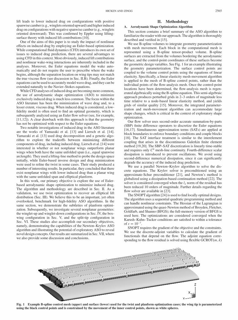
We use B-spline volumes to integrate geometry parameterizationwith mesh movement. Each block in the computational mesh isrepresented using a B-spline tensor-product volume. B-splinesurfaces are extracted from the volumes bordering the aerodynamicsurface, and the control-point coordinates of these surfaces becomethe geometric design variables. See Fig. 1 for an example illustratingthe geometry parameterization. The surface control points arecoupled to the volume control points using the equations of linearelasticity. Speci!cally, a linear elasticity mesh-movement algorithmis applied to the mesh of B-spline control points, rather than theindividual points of the "ow-analysis mesh. Once the control-pointlocations have been determined, the "ow-analysis mesh is regen-erated algebraically using the B-spline equation. This semi-algebraicapproach produces perturbed grids in 2–3 orders of magnitude lesstime relative to a node-based linear elasticity method, and yieldsgrids of similar quality [15]. Moreover, the integrated parameter-ization and mesh-movement algorithm can accommodate largeshape changes, which is critical in the context of exploratory shapeoptimization.
Our "ow solver uses second-order accurate summation-by-parts(SBP) !nite difference operators to discretize the Euler equations[16,17]. Simultaneous approximation terms (SATs) are applied atblock boundaries to enforce boundary conditions and couple blocks[18]. The SAT interface treatment is similar to the interelementcoupling that arises in the discontinuous Galerkin !nite elementmethod [19,20]. The SBP–SAT discretization is linearly time-stableand requires only C0 mesh-line continuity. Fourth-difference scalardissipation is introduced to prevent oscillations. We avoid usingsecond-difference numerical dissipation, since it can signi!cantlydegrade the accuracy of the induced drag prediction.
We use a parallel Newton–Krylov algorithm to solve the dis-crete equations. The Krylov solver is preconditioned using anapproximate-Schur preconditioner [21], and Newton’s method isglobalized using a dissipation-based continuation method [22]. Thesolver is considered converged when the l2 norm of the residual hasbeen reduced 10 orders of magnitude. Further details regarding the"ow solver are available in [23].
The SNOPTalgorithm [24] is used to !nd locally optimal designs.The algorithm uses a sequential quadratic programming method andcan handle nonlinear constraints. The Hessian of the Lagrangian isapproximated using the quasi-Newton method of Broyden, Fletcher,Goldfarb, and Shanno (BFGS); the full-memory version of BFGS isused here. The optimizations are considered converged when theKarush–Kuhn–Tucker conditions are satis!ed to within a toleranceof "! 10"7.
SNOPT requires the gradient of the objective and the constraints.We use the discrete-adjoint variables to calculate the gradient offunctionals that depend on the "ow. The adjoint equation corre-sponding to the "ow residual is solved using "exible GCROT#m; k$
Fig. 1 Example B-spline control mesh (upper) and surface (lower) used for the twist and planform optimization cases; the wing tip is parameterizedusing the black control points and is constrained by the movement of the inner control points, shown as white spheres.
HICKEN AND ZINGG 2565
with the approximate-Schur preconditioner; GCROT#m; k$ has beenshown to be robust and ef!cient compared with several othertruncated Krylov-subspace methods [25].
Gradient-based optimization algorithms, like SNOPT, perform alocal search of the design space, and there is no guarantee that theywill !nd the global optimum. The studies presented below use amodest number of degrees of freedom, and experience suggests thatthe design space is not particularly complex; hence, a multistartstrategy is often effective in locating additional local optima. Morecomplicated optimization problems will require an automated andef!cient search of the design space, and this remains an active area ofresearch.
B. Induced Drag Prediction
Induced drag is notoriously dif!cult to evaluate accurately. Thisdif!culty is observed in panel codes as well as Euler and Navier–Stokes solvers. It has been attributed to the thin shape of wings,poorly resolved pressure gradients, and fore-aft subtractive cancel-lation [8].
Modern panel codes model the wake roll-up explicitly by solvingfor the shape of the wake. Smith and Kroo [8,26] developed a hybridmethod to determine the wake shape and used this method to studyelliptical and crescent-shaped planforms. Their study showed thatmodelling thewake shape is important for nonplanar con!gurations,even when the nonplanar wake is a consequence of trailing-edgeshape as it is for the elliptical planform. They also concluded that aTrefftz-plane integration is more reliable than surface-based inte-gration for induced drag prediction, but only if the wake shape isaccurately modeled.
Induced drag can also be predicted from numerical solutions of theEuler equations; however, as mentioned in the introduction, thisapproach is not without dif!culties. Van Dam and Nikfetrat [27] andvan Dam et al. [28] were among the !rst to address the issuesassociated with calculating induced drag in Euler "ow solvers.Similar to panel codes, surface-based integrationwas found to be lessaccurate than wake-plane-based integration techniques. Wake-planeanalysis also provides themeans to decompose the drag into differentcomponents (induced drag, viscous drag, etc.). The vorticity in thewake can decay before reaching the wake-analysis plane due to thenumerical dissipation in CFD solvers. More recent wake-planeanalyses account for this transfer of energy by including entropycontributions in the induced drag calculation [29–31].
We have experimented with the wake-plane analysis of Giles andCummings [32] in an attempt to address the dif!culties associatedwith accurate prediction of induced drag. In our experience, thewake-plane drag prediction is more accurate on coarse grids, but ofsimilar accuracy to surface-based integration on !ner grids. Inaddition, we have observed nonmonotonic convergence of wake-based induced drag on !ne grids.
Based on ourmixed experiencewithwake-based drag analysis, wehave elected to use suf!ciently !ne mesh spacing to offset thepotential problems of surface-based drag prediction. Table 1 lists the
statistics for the baseline grids used in the following studies. Somevariation in themesh spacingwill occurwhen the grids are perturbed.However, the wall-normal spacing remains on the order of 10"3 forthe duration of an optimization. To con!rm the predicted forces onthe optimal designs, we repeat the "ow analysis for these shapesusing re!ned grids with a factor of 3 to 4 more nodes in eachcoordinate direction. The re!ned grids are obtained using the B-spline volumes, which ensures that the surface nodes coincide withthe predicted optimal shapes. Table 1 lists representative statistics forthe re!ned grids immediately below their corresponding coarsegrids. The re!ned grids are used to produce all spanwise lift- anddrag-distribution plots.
The far-!eld boundary is at least 22 chord lengths from the surfacegeometry on all grids. In their study, Phillips et al. [12] found thatdoubling the far-!eld distance from 10 to 20 chord lengths changedthe induced drag by less than 1%, which suggests that 22 chordlengths is a conservative choice.
Euler codes often produce tip vortices that release off the side ofthewing tip, rather than at the trailing edge. This side-edge separationdeserves some discussion, because it in"uences the induced drag bycreating a nonplanar wake (see [9] as well as Sec. III). While itsaccurate prediction with an Euler code is debatable, edge separationis a real phenomenon [33], which has even been observed on wingswith rounded tips [34,35]. Thus, the perspective taken here is to studythe role of edge separation on induced drag, while acknowledgingthat the separation location and vortex size may not correspond withthe true (viscous) "ow.
C. De!nitions and ConventionsWe use the freestream values of the density and sound speed to
nondimensionalize the "owvariables. The characteristic length is theinitial root chord of the con!guration. For all of the studies we use a!xed Mach number ofM! 0:5. This Mach number ensures that the"ow remains subsonic for the geometries considered. We acknowl-edge that practical aerodynamic designs must consider multipleoperating conditions; however, induced drag depends only weaklyon Mach number [9], so our conclusions should be applicable to awide range of "ows.
The coef!cients of lift and drag are de!ned as
CL ! L
q1Sand CD ! D
q1S
respectively, where S is the reference area (see subsequentdiscussion) and q1 ! 1
2"1U2
1 is the dynamic pressure. When onlyvortex drag is present, the coef!cient of drag can be expressed as
CD ! C2L
#"e! CD;ellip
e(1)
where "! b2=S is the aspect ratio, b is the span, and CD;ellip is theminimum induced drag predicted by lifting-line theory for a planarwake. The parameter e is the span ef!ciency. Ideally, the spanef!ciency would depend only on geometry, but, in general, it may bea function of the coef!cient of lift [1]. However, this dependence isoften weak, so span ef!ciency remains a useful and popular means ofcomparing the induced drag of different con!gurations.
Rearranging Eq. (1) we have
e! C2L
#"CD
! L2
q1b2D
This suggests there are two distinct ways of isolating the effects ofgeometry on the span ef!ciency: 1) minimize CD while holding CL
and" !xed, or 2)minimizeDwhile holdingL and b !xed.However,neither one of these choices is suf!cient to guarantee a uniquegeometry in an inviscid "ow. To appreciate why, consider a lifting-line analysis of an elliptically shaped planform, which will yield aspan ef!ciency of e! 1. The aspect ratio and coef!cient of lift can beheld !xed while the geometry undergoes an isotropic scaling. Thus,there is an in!nite family of geometries that meet the constraints and
Table 1 Dimensions and length parameters (in root-chord units)for the grids used in the studies
Study Blocks Grid size Spacing Far-!elddistanceb
(Nodes) Off-wall Surfacea
Twist, planformCoarse 18 1 381 050 0.00374 0.0278 36.8Fine 1152 88 387 200 0.00086 0.0070 36.8Winglet, box wingCoarse 48 5 647 152 0.00072 0.0153 22.0Fine 1296 152 473 104 0.00013 0.0060 22.0Wing with split tipCoarse 42 3 827 250 0.00050 0.0187 22.0Fine 1134 103 335 750 0.00017 0.0062 22.0
aAverage surface spacing %!!!!!!!!!!!!!!!S=Nsurf
p, where S is the area, and Nsurf is the number
of cells on the surface.bMinimum distance to the far-!eld boundary.
2566 HICKEN AND ZINGG
achieve the sameCD. A similar nonuniqueness arises if we constrainonly L and b. By varying the root chord, we can create a set ofgeometries with elliptical planforms and !xed span, and each geo-metry in this family can achieve the same lift with an appropriatelychosen angle of attack.
Constraining either CL or L, and any two of b, S, and ", issuf!cient to produce a unique design. In the studies below, weconstrain the span and the reference area. We then choose a liftconstraint based on S such that CL ! 0:375 for all geometries.
Unless stated otherwise, the reference area is the planform area ofthe geometry (i.e., the area projected onto the xy-plane). Theplanform area is calculated using derivatives of the coordinatetransformations. For example, suppose the surface coincideswith thecomputational plane $! 0. Then the surface area is approximated by
S& 1
2
X
j
X
k
"j@z$jJ
#
jk
wkwj
where J is the Jacobian of the mapping, and the sum is taken over allnodes #j; k$ on the surface. Coordinate-mapping derivatives, such as@z$, are available from the second-order accurate discretization of thegoverning equations. The weights wj and wk are based on the trap-ezoid rule, which produces a second-order accurate estimate for S.The integration includes contributions from both sides of a geometry,so the factor of 1=2 ensures that the resulting surface area isconsistent with the projected area for planar geometries. Thesensitivities of the surface areawith respect to the designvariables arecalculated analytically.
III. ValidationAccording to linear aerodynamic theory, an elliptical spanwise lift
distribution produces the minimum induced drag when the wake isplanar. This provides a challenging benchmark for optimizationalgorithms, because an order-% perturbation of the elliptical liftdistribution produces an order-%2 perturbation in the induced drag[36]. Hence, obtaining the elliptical lift distribution requiressuf!cient accuracy in the drag prediction.
Elliptical lift distributions are not unique to one geometry. Thesame distribution can be obtained using changes in planform, twist,sectional lift, or some combination of these. We !rst consider twistoptimization to recover an elliptical lift distribution; subsequently,we investigate planform optimization.
Both the twist and planform optimizations use the 18 block griddescribed in Table 1. They also share a common wing geometry andparameterization, which is shown in Fig. 1. Thewing geometry has aspan of six root-chord units, NACA 0012 airfoil sections, and aninitially rectangular planform shape. Thewing consists of an inboardsection over 97.5% of the semispan and a wing-tip cap over the last2.5% of the semispan. The upper and lower surfaces of the inboardsection are parameterized using 9 B-spline control points in thestreamwise direction and 5 to 15 control points in the spanwisedirection (white spheres in Fig. 1). The number of spanwise controlpoints is varied to ensure the optimal loading has been achieved.
The wing-tip cap is parameterized using two B-spline patches(upper and lower surfaces) consisting of 9 ' 4 control points in thestreamwise and spanwise directions, respectively. The three out-board control points of these patches, shown as dark spheres in Fig. 1,are controlled by the movement of the inboard section such thatchanges in the cap shape are limited to linear shears.
A. Twist OptimizationFor twist optimization, the inboard control-point sections are free
to rotate about a !xed trailing edge, i.e., the effective designvariablesare the local angles of attack. Fixing the trailing edge helps reducenonplanar effects, although wing-tip edge separation makes acompletely planar wake dif!cult to achieve. The angle of attack is setsuch that the initial geometry meets the CL constraint of 0.375, andthe projected area is constrained at its initial value of S! 6.
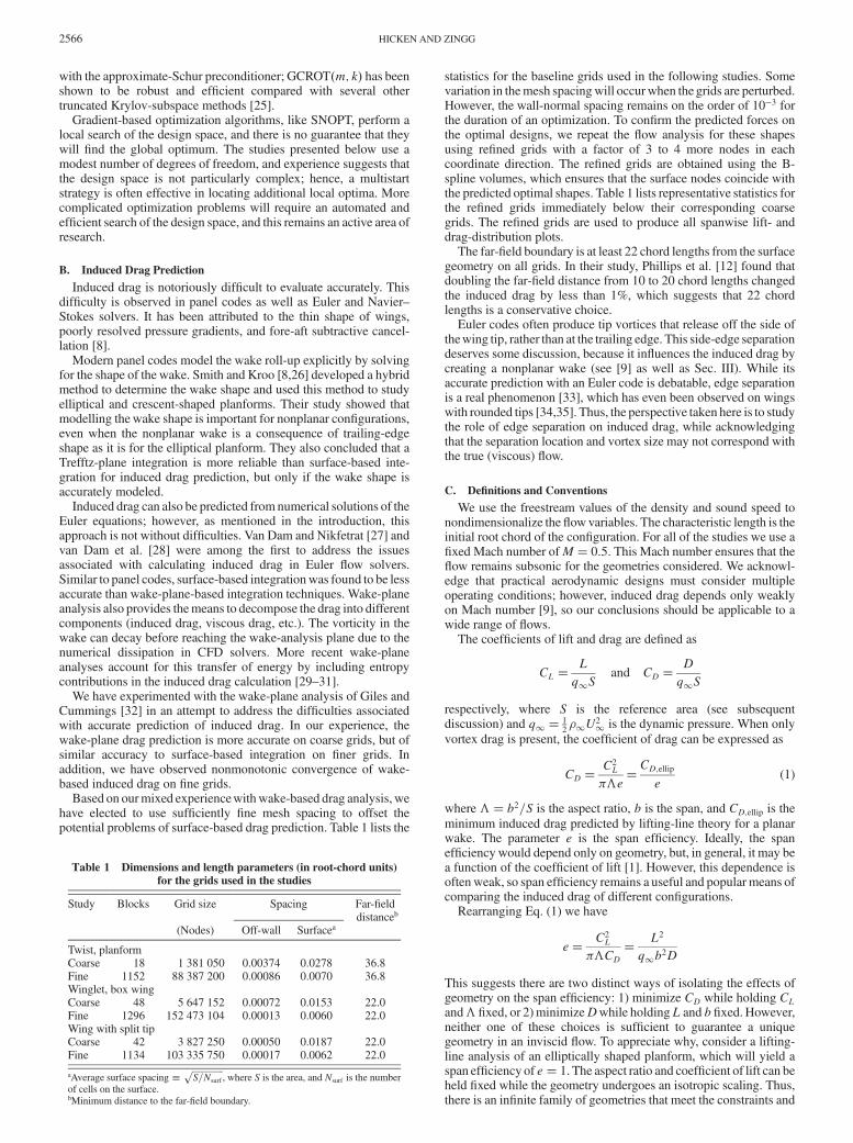
Figure 2 plots the span ef!ciency of the optimally twistedgeometries versus the number of spanwise control points on theinboard section. For twist optimization, we see that the span ef!-ciency is relatively constant over the range of spanwise control pointsconsidered. With 15 spanwise control points, the span ef!ciency isapproximately e! 0:993, in excellent agreement with the lifting-lineprediction of e! 1.
To con!rm the predicted span ef!ciency, the B-spline meshcorresponding to the 15 spanwise-control-point case was re!ned byincreasing the number of nodes by a factor of 4 in each direction. Theresulting grid has the nodal density of the 1152 block grid in Table 1.Using the re!ned grid, the predicted coef!cients of lift and drag areCL ! 0:37889 andCD ! 0:00766, respectively, and the revised spanef!ciency is e! 0:994. For comparison, the initial untwistedgeometry has a predicted span ef!ciency of e! 0:978, based on are!ned grid.
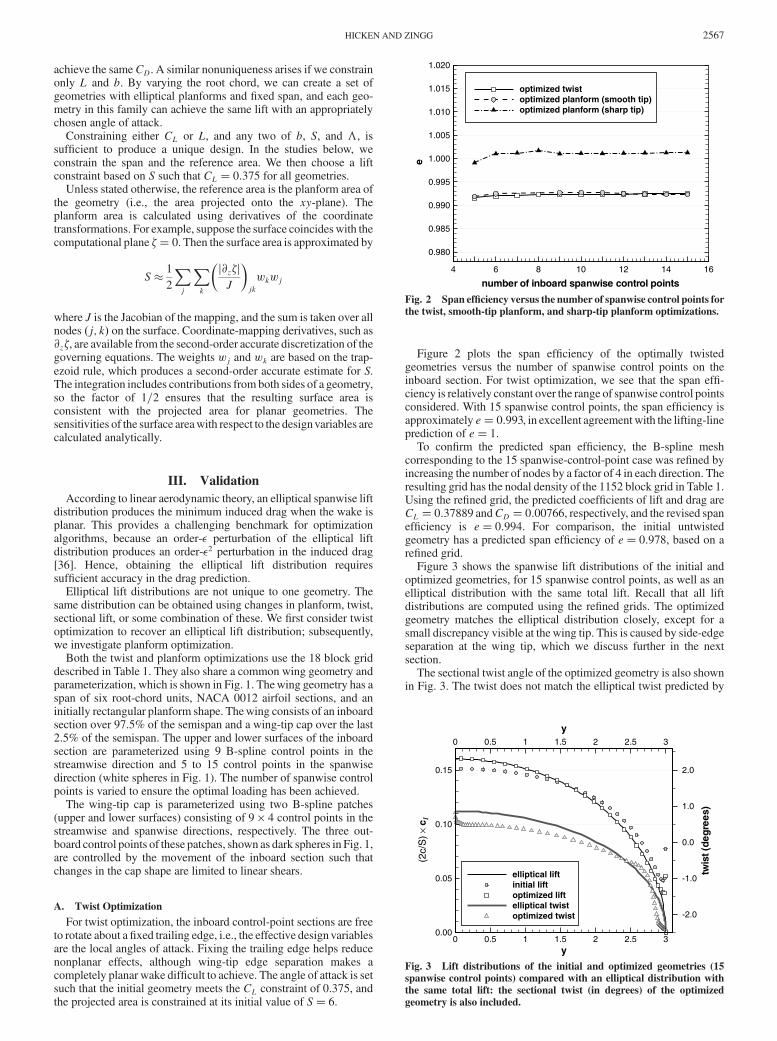
Figure 3 shows the spanwise lift distributions of the initial andoptimized geometries, for 15 spanwise control points, as well as anelliptical distribution with the same total lift. Recall that all liftdistributions are computed using the re!ned grids. The optimizedgeometry matches the elliptical distribution closely, except for asmall discrepancy visible at the wing tip. This is caused by side-edgeseparation at the wing tip, which we discuss further in the nextsection.
The sectional twist angle of the optimized geometry is also shownin Fig. 3. The twist does not match the elliptical twist predicted by
number of inboard spanwise control points
e
4 6 8 10 12 14 16
0.980
0.985
0.990
0.995
1.000
1.005
1.010
1.015
1.020
optimized twistoptimized planform (smooth tip)optimized planform (sharp tip)
Fig. 2 Span ef!ciency versus the number of spanwise control points forthe twist, smooth-tip planform, and sharp-tip planform optimizations.
y
y
(2c/
S)!
c l
twis
t(de
gree
s)
0
0
0.5
0.5
1
1
1.5
1.5
2
2
2.5
2.5
3
3
0.00
0.05
0.10
0.15
-2.0
-1.0
0.0
1.0
2.0
elliptical liftinitial liftoptimized liftelliptical twistoptimized twist
Fig. 3 Lift distributions of the initial and optimized geometries (15spanwise control points) compared with an elliptical distribution withthe same total lift: the sectional twist (in degrees) of the optimizedgeometry is also included.
HICKEN AND ZINGG 2567
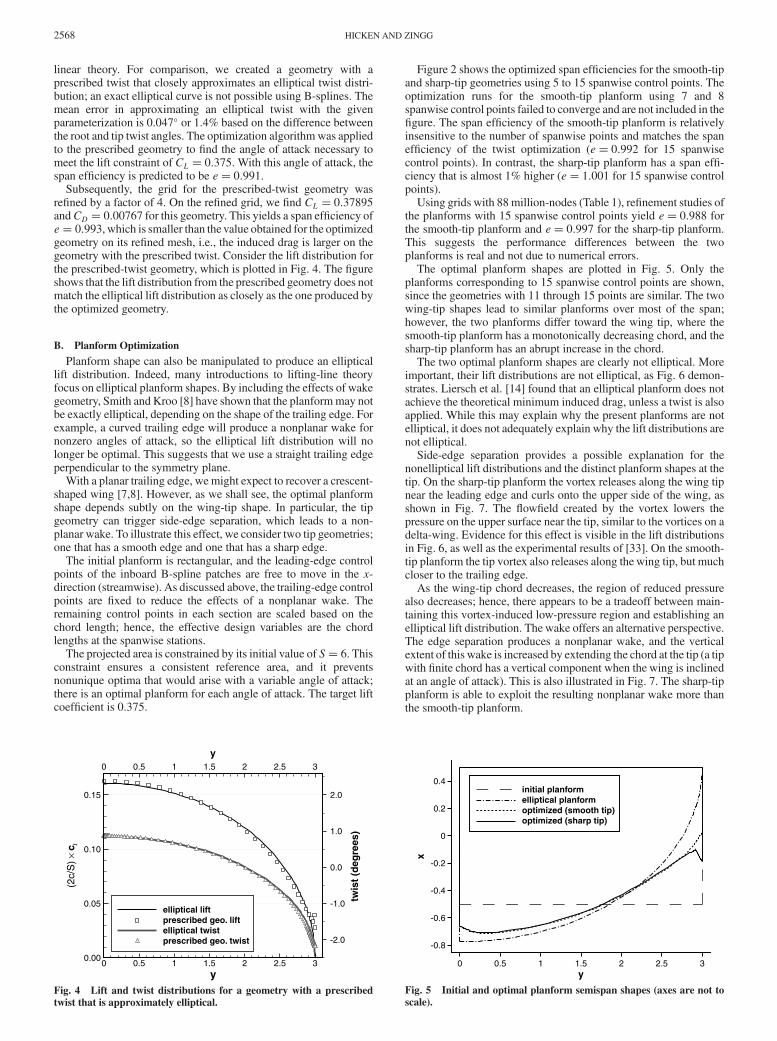
linear theory. For comparison, we created a geometry with aprescribed twist that closely approximates an elliptical twist distri-bution; an exact elliptical curve is not possible using B-splines. Themean error in approximating an elliptical twist with the givenparameterization is 0.047( or 1.4% based on the difference betweenthe root and tip twist angles. The optimization algorithmwas appliedto the prescribed geometry to !nd the angle of attack necessary tomeet the lift constraint of CL ! 0:375. With this angle of attack, thespan ef!ciency is predicted to be e! 0:991.
Subsequently, the grid for the prescribed-twist geometry wasre!ned by a factor of 4. On the re!ned grid, we !nd CL ! 0:37895andCD ! 0:00767 for this geometry. This yields a span ef!ciency ofe! 0:993, which is smaller than the value obtained for the optimizedgeometry on its re!ned mesh, i.e., the induced drag is larger on thegeometry with the prescribed twist. Consider the lift distribution forthe prescribed-twist geometry, which is plotted in Fig. 4. The !gureshows that the lift distribution from the prescribed geometry does notmatch the elliptical lift distribution as closely as the one produced bythe optimized geometry.
B. Planform Optimization
Planform shape can also be manipulated to produce an ellipticallift distribution. Indeed, many introductions to lifting-line theoryfocus on elliptical planform shapes. By including the effects of wakegeometry, Smith and Kroo [8] have shown that the planformmay notbe exactly elliptical, depending on the shape of the trailing edge. Forexample, a curved trailing edge will produce a nonplanar wake fornonzero angles of attack, so the elliptical lift distribution will nolonger be optimal. This suggests that we use a straight trailing edgeperpendicular to the symmetry plane.
With a planar trailing edge, we might expect to recover a crescent-shaped wing [7,8]. However, as we shall see, the optimal planformshape depends subtly on the wing-tip shape. In particular, the tipgeometry can trigger side-edge separation, which leads to a non-planar wake. To illustrate this effect, we consider two tip geometries;one that has a smooth edge and one that has a sharp edge.
The initial planform is rectangular, and the leading-edge controlpoints of the inboard B-spline patches are free to move in the x-direction (streamwise). As discussed above, the trailing-edge controlpoints are !xed to reduce the effects of a nonplanar wake. Theremaining control points in each section are scaled based on thechord length; hence, the effective design variables are the chordlengths at the spanwise stations.
The projected area is constrained by its initial value of S! 6. Thisconstraint ensures a consistent reference area, and it preventsnonunique optima that would arise with a variable angle of attack;there is an optimal planform for each angle of attack. The target liftcoef!cient is 0.375.
Figure 2 shows the optimized span ef!ciencies for the smooth-tipand sharp-tip geometries using 5 to 15 spanwise control points. Theoptimization runs for the smooth-tip planform using 7 and 8spanwise control points failed to converge and are not included in the!gure. The span ef!ciency of the smooth-tip planform is relativelyinsensitive to the number of spanwise points and matches the spanef!ciency of the twist optimization (e! 0:992 for 15 spanwisecontrol points). In contrast, the sharp-tip planform has a span ef!-ciency that is almost 1% higher (e! 1:001 for 15 spanwise controlpoints).
Using grids with 88 million-nodes (Table 1), re!nement studies ofthe planforms with 15 spanwise control points yield e! 0:988 forthe smooth-tip planform and e! 0:997 for the sharp-tip planform.This suggests the performance differences between the twoplanforms is real and not due to numerical errors.
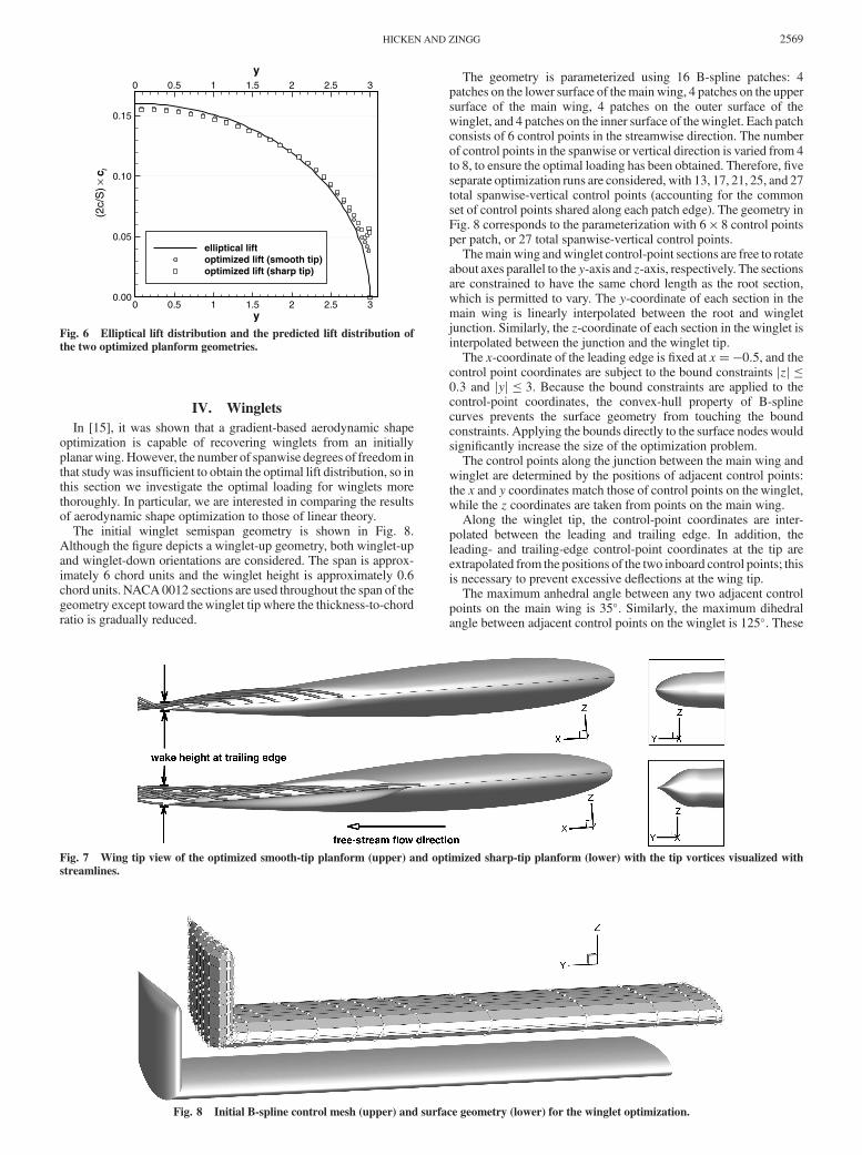
The optimal planform shapes are plotted in Fig. 5. Only theplanforms corresponding to 15 spanwise control points are shown,since the geometries with 11 through 15 points are similar. The twowing-tip shapes lead to similar planforms over most of the span;however, the two planforms differ toward the wing tip, where thesmooth-tip planform has a monotonically decreasing chord, and thesharp-tip planform has an abrupt increase in the chord.
The two optimal planform shapes are clearly not elliptical. Moreimportant, their lift distributions are not elliptical, as Fig. 6 demon-strates. Liersch et al. [14] found that an elliptical planform does notachieve the theoretical minimum induced drag, unless a twist is alsoapplied. While this may explain why the present planforms are notelliptical, it does not adequately explain why the lift distributions arenot elliptical.
Side-edge separation provides a possible explanation for thenonelliptical lift distributions and the distinct planform shapes at thetip. On the sharp-tip planform the vortex releases along the wing tipnear the leading edge and curls onto the upper side of the wing, asshown in Fig. 7. The "ow!eld created by the vortex lowers thepressure on the upper surface near the tip, similar to the vortices on adelta-wing. Evidence for this effect is visible in the lift distributionsin Fig. 6, as well as the experimental results of [33]. On the smooth-tip planform the tip vortex also releases along the wing tip, but muchcloser to the trailing edge.
As the wing-tip chord decreases, the region of reduced pressurealso decreases; hence, there appears to be a tradeoff between main-taining this vortex-induced low-pressure region and establishing anelliptical lift distribution. The wake offers an alternative perspective.The edge separation produces a nonplanar wake, and the verticalextent of this wake is increased by extending the chord at the tip (a tipwith !nite chord has a vertical component when the wing is inclinedat an angle of attack). This is also illustrated in Fig. 7. The sharp-tipplanform is able to exploit the resulting nonplanar wake more thanthe smooth-tip planform.
y
y
(2c/
S)!
c l
twis
t (de
gree
s)
0
0
0.5
0.5
1
1
1.5
1.5
2
2
2.5
2.5
3
3
0.00
0.05
0.10
0.15
-2.0
-1.0
0.0
1.0
2.0
elliptical liftprescribed geo. liftelliptical twistprescribed geo. twist
Fig. 4 Lift and twist distributions for a geometry with a prescribedtwist that is approximately elliptical.
y
x
0 0.5 1 1.5 2 2.5 3
-0.8
-0.6
-0.4
-0.2
0
0.2
0.4initial planformelliptical planformoptimized (smooth tip)optimized (sharp tip)
Fig. 5 Initial and optimal planform semispan shapes (axes are not toscale).
2568 HICKEN AND ZINGG
IV. WingletsIn [15], it was shown that a gradient-based aerodynamic shape
optimization is capable of recovering winglets from an initiallyplanarwing.However, the number of spanwise degrees of freedom inthat studywas insuf!cient to obtain the optimal lift distribution, so inthis section we investigate the optimal loading for winglets morethoroughly. In particular, we are interested in comparing the resultsof aerodynamic shape optimization to those of linear theory.
The initial winglet semispan geometry is shown in Fig. 8.Although the !gure depicts a winglet-up geometry, both winglet-upand winglet-down orientations are considered. The span is approx-imately 6 chord units and the winglet height is approximately 0.6chord units. NACA0012 sections are used throughout the span of thegeometry except toward thewinglet tip where the thickness-to-chordratio is gradually reduced.
The geometry is parameterized using 16 B-spline patches: 4patches on the lower surface of themain wing, 4 patches on the uppersurface of the main wing, 4 patches on the outer surface of thewinglet, and 4 patches on the inner surface of thewinglet. Each patchconsists of 6 control points in the streamwise direction. The numberof control points in the spanwise or vertical direction is varied from 4to 8, to ensure the optimal loading has been obtained. Therefore, !veseparate optimization runs are considered, with 13, 17, 21, 25, and 27total spanwise-vertical control points (accounting for the commonset of control points shared along each patch edge). The geometry inFig. 8 corresponds to the parameterization with 6 ' 8 control pointsper patch, or 27 total spanwise-vertical control points.
Themainwing andwinglet control-point sections are free to rotateabout axes parallel to the y-axis and z-axis, respectively. The sectionsare constrained to have the same chord length as the root section,which is permitted to vary. The y-coordinate of each section in themain wing is linearly interpolated between the root and wingletjunction. Similarly, the z-coordinate of each section in the winglet isinterpolated between the junction and the winglet tip.
The x-coordinate of the leading edge is !xed at x!"0:5, and thecontrol point coordinates are subject to the bound constraints jzj )0:3 and jyj ) 3. Because the bound constraints are applied to thecontrol-point coordinates, the convex-hull property of B-splinecurves prevents the surface geometry from touching the boundconstraints. Applying the bounds directly to the surface nodes wouldsigni!cantly increase the size of the optimization problem.
The control points along the junction between the main wing andwinglet are determined by the positions of adjacent control points:the x and y coordinates match those of control points on the winglet,while the z coordinates are taken from points on the main wing.
Along the winglet tip, the control-point coordinates are inter-polated between the leading and trailing edge. In addition, theleading- and trailing-edge control-point coordinates at the tip areextrapolated from the positions of the two inboard control points; thisis necessary to prevent excessive de"ections at the wing tip.
The maximum anhedral angle between any two adjacent controlpoints on the main wing is 35(. Similarly, the maximum dihedralangle between adjacent control points on the winglet is 125(. These
y
y
(2c/
S)!
c l
0
0
0.5
0.5
1
1
1.5
1.5
2
2
2.5
2.5
3
3
0.00
0.05
0.10
0.15
elliptical liftoptimized lift (smooth tip)optimized lift (sharp tip)
Fig. 6 Elliptical lift distribution and the predicted lift distribution ofthe two optimized planform geometries.
Fig. 7 Wing tip view of the optimized smooth-tip planform (upper) and optimized sharp-tip planform (lower) with the tip vortices visualized withstreamlines.
Fig. 8 Initial B-spline control mesh (upper) and surface geometry (lower) for the winglet optimization.
HICKEN AND ZINGG 2569
constraints are necessary to prevent invalid geometries and meshesnear the winglet junction, a problem that we elaborate on below.
The 48-block grid from Table 1 is used for all optimization runs.As usual, the coef!cient of lift is constrained at 0.375 and an equalityconstraint of S! 6 is imposed on the projected area.
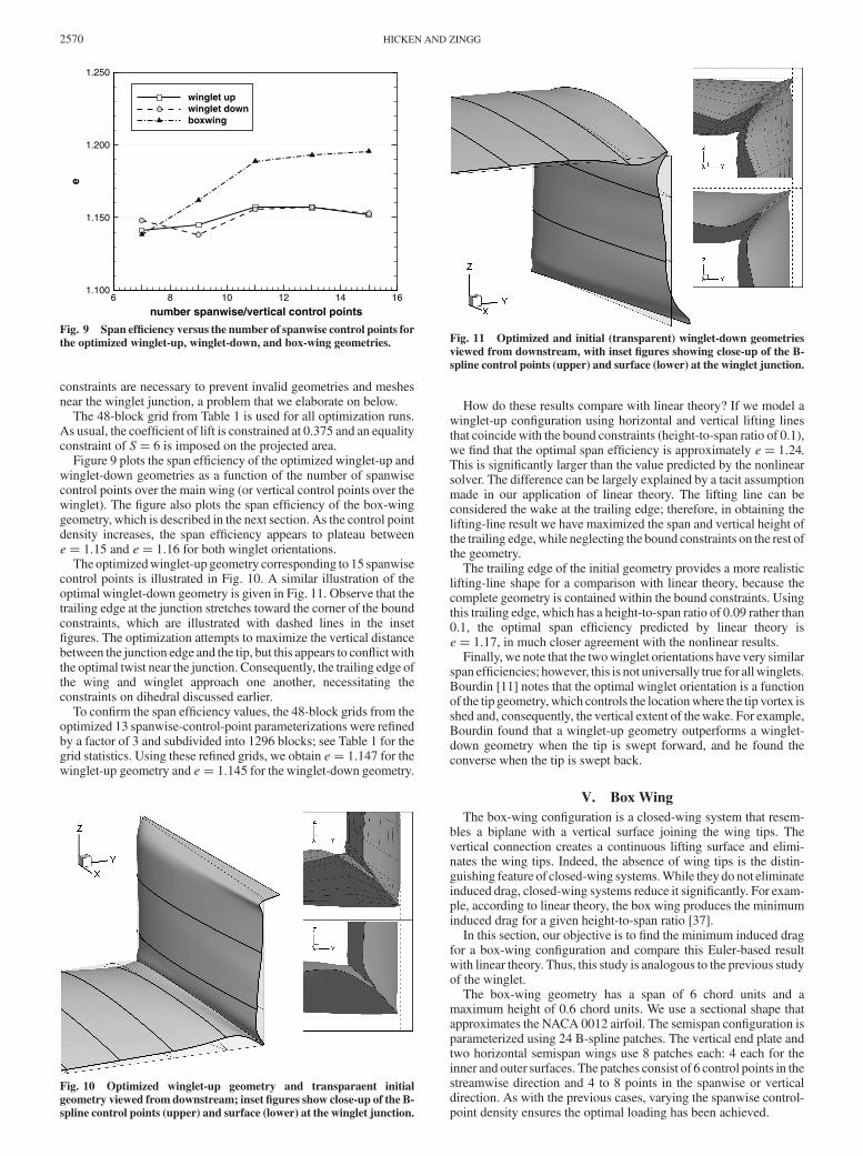
Figure 9 plots the span ef!ciency of the optimized winglet-up andwinglet-down geometries as a function of the number of spanwisecontrol points over the main wing (or vertical control points over thewinglet). The !gure also plots the span ef!ciency of the box-winggeometry, which is described in the next section. As the control pointdensity increases, the span ef!ciency appears to plateau betweene! 1:15 and e! 1:16 for both winglet orientations.
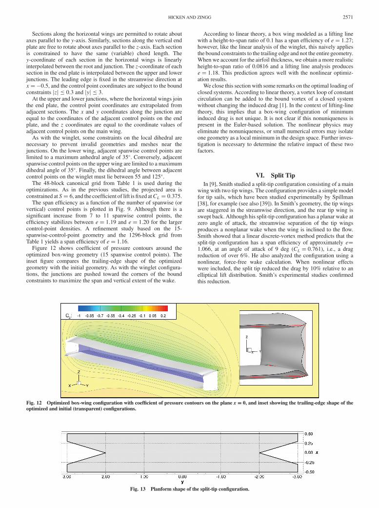
The optimizedwinglet-up geometry corresponding to 15 spanwisecontrol points is illustrated in Fig. 10. A similar illustration of theoptimal winglet-down geometry is given in Fig. 11. Observe that thetrailing edge at the junction stretches toward the corner of the boundconstraints, which are illustrated with dashed lines in the inset!gures. The optimization attempts to maximize the vertical distancebetween the junction edge and the tip, but this appears to con"ict withthe optimal twist near the junction. Consequently, the trailing edge ofthe wing and winglet approach one another, necessitating theconstraints on dihedral discussed earlier.
To con!rm the span ef!ciency values, the 48-block grids from theoptimized 13 spanwise-control-point parameterizations were re!nedby a factor of 3 and subdivided into 1296 blocks; see Table 1 for thegrid statistics. Using these re!ned grids, we obtain e! 1:147 for thewinglet-up geometry and e! 1:145 for the winglet-down geometry.
How do these results compare with linear theory? If we model awinglet-up con!guration using horizontal and vertical lifting linesthat coincidewith the bound constraints (height-to-span ratio of 0.1),we !nd that the optimal span ef!ciency is approximately e! 1:24.This is signi!cantly larger than the value predicted by the nonlinearsolver. The difference can be largely explained by a tacit assumptionmade in our application of linear theory. The lifting line can beconsidered the wake at the trailing edge; therefore, in obtaining thelifting-line result we have maximized the span and vertical height ofthe trailing edge,while neglecting the bound constraints on the rest ofthe geometry.
The trailing edge of the initial geometry provides a more realisticlifting-line shape for a comparison with linear theory, because thecomplete geometry is contained within the bound constraints. Usingthis trailing edge, which has a height-to-span ratio of 0.09 rather than0.1, the optimal span ef!ciency predicted by linear theory ise! 1:17, in much closer agreement with the nonlinear results.
Finally, we note that the twowinglet orientations have very similarspan ef!ciencies; however, this is not universally true for allwinglets.Bourdin [11] notes that the optimal winglet orientation is a functionof the tip geometry,which controls the locationwhere the tip vortex isshed and, consequently, the vertical extent of thewake. For example,Bourdin found that a winglet-up geometry outperforms a winglet-down geometry when the tip is swept forward, and he found theconverse when the tip is swept back.
V. Box WingThe box-wing con!guration is a closed-wing system that resem-
bles a biplane with a vertical surface joining the wing tips. Thevertical connection creates a continuous lifting surface and elimi-nates the wing tips. Indeed, the absence of wing tips is the distin-guishing feature of closed-wing systems.While they do not eliminateinduced drag, closed-wing systems reduce it signi!cantly. For exam-ple, according to linear theory, the box wing produces the minimuminduced drag for a given height-to-span ratio [37].
In this section, our objective is to !nd the minimum induced dragfor a box-wing con!guration and compare this Euler-based resultwith linear theory. Thus, this study is analogous to the previous studyof the winglet.
The box-wing geometry has a span of 6 chord units and amaximum height of 0.6 chord units. We use a sectional shape thatapproximates the NACA 0012 airfoil. The semispan con!guration isparameterized using 24 B-spline patches. The vertical end plate andtwo horizontal semispan wings use 8 patches each: 4 each for theinner and outer surfaces. The patches consist of 6 control points in thestreamwise direction and 4 to 8 points in the spanwise or verticaldirection. As with the previous cases, varying the spanwise control-point density ensures the optimal loading has been achieved.
number spanwise/vertical control points
e
6 8 10 12 14 161.100
1.150
1.200
1.250
winglet upwinglet downboxwing
Fig. 9 Span ef!ciency versus the number of spanwise control points forthe optimized winglet-up, winglet-down, and box-wing geometries.
Fig. 10 Optimized winglet-up geometry and transparaent initialgeometry viewed from downstream; inset !gures show close-up of the B-spline control points (upper) and surface (lower) at the winglet junction.
Fig. 11 Optimized and initial (transparent) winglet-down geometriesviewed from downstream, with inset !gures showing close-up of the B-spline control points (upper) and surface (lower) at the winglet junction.
2570 HICKEN AND ZINGG
Sections along the horizontal wings are permitted to rotate aboutaxes parallel to the y-axis. Similarly, sections along the vertical endplate are free to rotate about axes parallel to the z-axis. Each sectionis constrained to have the same (variable) chord length. They-coordinate of each section in the horizontal wings is linearlyinterpolated between the root and junction. The z-coordinate of eachsection in the end plate is interpolated between the upper and lowerjunctions. The leading edge is !xed in the streamwise direction atx!"0:5, and the control point coordinates are subject to the boundconstraints jzj ) 0:3 and jyj ) 3.
At the upper and lower junctions, where the horizontal wings jointhe end plate, the control point coordinates are extrapolated fromadjacent sections. The x and y coordinates along the junction areequal to the coordinates of the adjacent control points on the endplate, and the z coordinates are equal to the coordinate values ofadjacent control points on the main wing.
As with the winglet, some constraints on the local dihedral arenecessary to prevent invalid geometries and meshes near thejunctions. On the lower wing, adjacent spanwise control points arelimited to a maximum anhedral angle of 35(. Conversely, adjacentspanwise control points on the upper wing are limited to a maximumdihedral angle of 35(. Finally, the dihedral angle between adjacentcontrol points on the winglet must lie between 55 and 125(.
The 48-block canonical grid from Table 1 is used during theoptimizations. As in the previous studies, the projected area isconstrained atS! 6, and the coef!cient of lift is!xed atCL ! 0:375.
The span ef!ciency as a function of the number of spanwise (orvertical) control points is plotted in Fig. 9. Although there is asigni!cant increase from 7 to 11 spanwise control points, theef!ciency stabilizes between e! 1:19 and e! 1:20 for the largercontrol-point densities. A re!nement study based on the 15-spanwise-control-point geometry and the 1296-block grid fromTable 1 yields a span ef!ciency of e! 1:16.
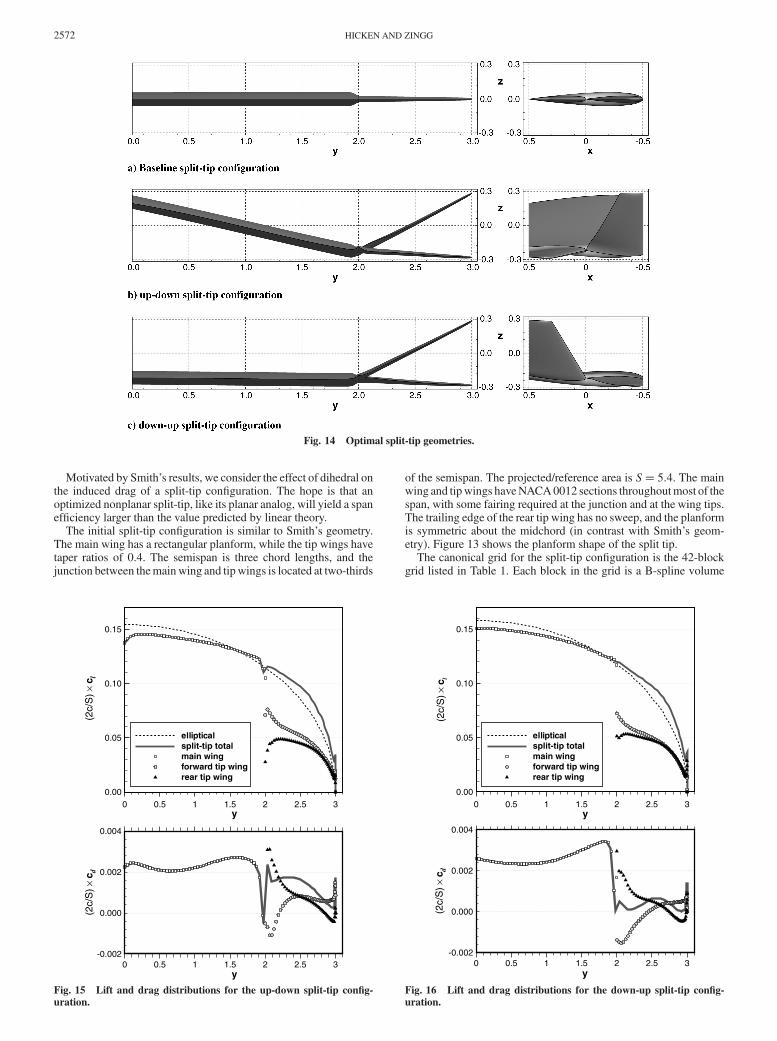
Figure 12 shows coef!cient of pressure contours around theoptimized box-wing geometry (15 spanwise control points). Theinset !gure compares the trailing-edge shape of the optimizedgeometry with the initial geometry. As with the winglet con!gura-tions, the junctions are pushed toward the corners of the boundconstraints to maximize the span and vertical extent of the wake.
According to linear theory, a box wing modeled as a lifting linewith a height-to-span ratio of 0.1 has a span ef!ciency of e! 1:27;however, like the linear analysis of the winglet, this naively appliesthe bound constraints to the trailing edge and not the entire geometry.When we account for the airfoil thickness, we obtain a more realisticheight-to-span ratio of 0.0816 and a lifting line analysis producese! 1:18. This prediction agrees well with the nonlinear optimiz-ation results.
We close this section with some remarks on the optimal loading ofclosed systems. According to linear theory, a vortex loop of constantcirculation can be added to the bound vortex of a closed systemwithout changing the induced drag [1]. In the context of lifting-linetheory, this implies that a box-wing con!guration of minimuminduced drag is not unique. It is not clear if this nonuniqueness ispresent in the Euler-based solution. The nonlinear physics mayeliminate the nonuniqueness, or small numerical errors may isolateone geometry as a local minimum in the design space. Further inves-tigation is necessary to determine the relative impact of these twofactors.
VI. Split TipIn [9], Smith studied a split-tip con!guration consisting of a main
wing with two tip wings. The con!guration provides a simple modelfor tip sails, which have been studied experimentally by Spillman[38], for example (see also [39]). In Smith’s geometry, the tip wingsare staggered in the streamwise direction, and the rear tip wing isswept back. Although his split-tip con!guration has a planar wake atzero angle of attack, the streamwise separation of the tip wingsproduces a nonplanar wake when the wing is inclined to the "ow.Smith showed that a linear discrete-vortex method predicts that thesplit-tip con!guration has a span ef!ciency of approximately e!1:066, at an angle of attack of 9 deg (CL ! 0:761), i.e., a dragreduction of over 6%. He also analyzed the con!guration using anonlinear, force-free wake calculation. When nonlinear effectswere included, the split tip reduced the drag by 10% relative to anelliptical lift distribution. Smith’s experimental studies con!rmedthis reduction.
Fig. 12 Optimized box-wing con!guration with coef!cient of pressure contours on the plane x! 0, and inset showing the trailing-edge shape of theoptimized and initial (transparent) con!gurations.
Fig. 13 Planform shape of the split-tip con!guration.
HICKEN AND ZINGG 2571
Motivated by Smith’s results, we consider the effect of dihedral onthe induced drag of a split-tip con!guration. The hope is that anoptimized nonplanar split-tip, like its planar analog, will yield a spanef!ciency larger than the value predicted by linear theory.
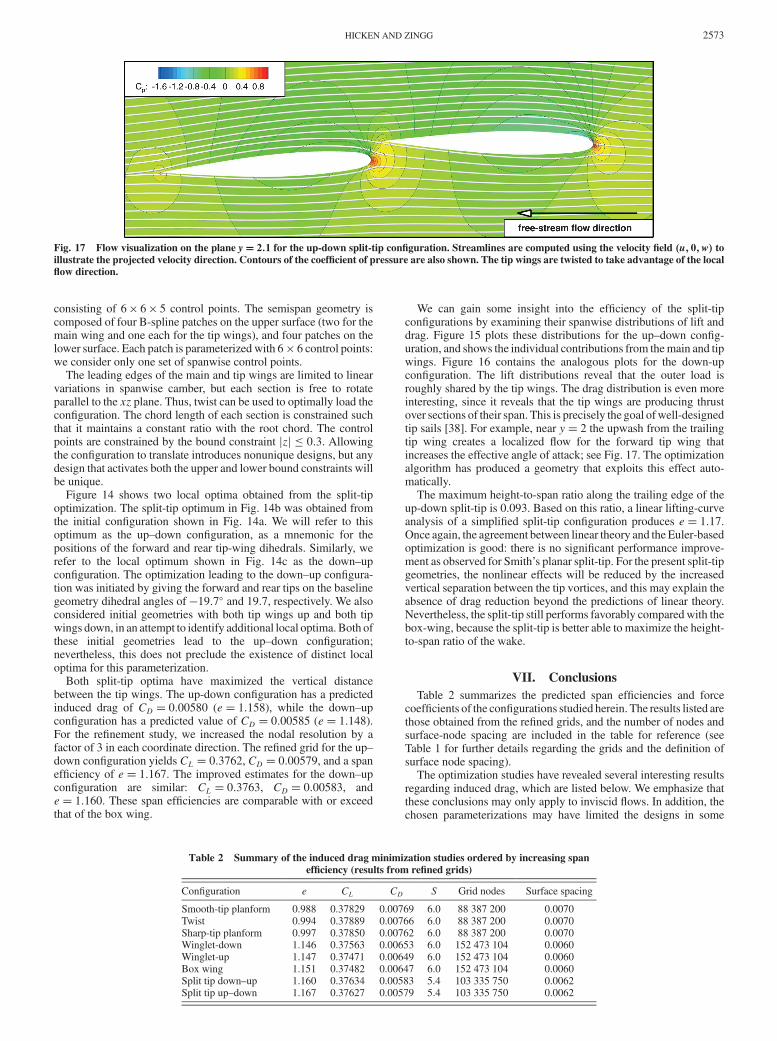
The initial split-tip con!guration is similar to Smith’s geometry.The main wing has a rectangular planform, while the tip wings havetaper ratios of 0.4. The semispan is three chord lengths, and thejunction between themainwing and tipwings is located at two-thirds
of the semispan. The projected/reference area is S! 5:4. The mainwing and tipwings haveNACA0012 sections throughoutmost of thespan, with some fairing required at the junction and at the wing tips.The trailing edge of the rear tip wing has no sweep, and the planformis symmetric about the midchord (in contrast with Smith’s geom-etry). Figure 13 shows the planform shape of the split tip.
The canonical grid for the split-tip con!guration is the 42-blockgrid listed in Table 1. Each block in the grid is a B-spline volume
Fig. 14 Optimal split-tip geometries.
y
(2c/
S)!
c d
0 0.5 1 1.5 2 2.5 3-0.002
0.000
0.002
0.004
y
(2c/
S)!
c l
0 0.5 1 1.5 2 2.5 30.00
0.05
0.10
0.15
ellipticalsplit-tip totalmain wingforward tip wingrear tip wing
Fig. 15 Lift and drag distributions for the up-down split-tip con!g-uration.
y
(2c/
S)!
c d
0 0.5 1 1.5 2 2.5 3-0.002
0.000
0.002
0.004
y
(2c/
S)!
c l
0 0.5 1 1.5 2 2.5 30.00
0.05
0.10
0.15
ellipticalsplit-tip totalmain wingforward tip wingrear tip wing
Fig. 16 Lift and drag distributions for the down-up split-tip con!g-uration.
2572 HICKEN AND ZINGG
consisting of 6 ' 6 ' 5 control points. The semispan geometry iscomposed of four B-spline patches on the upper surface (two for themain wing and one each for the tip wings), and four patches on thelower surface. Each patch is parameterized with 6 ' 6 control points:we consider only one set of spanwise control points.
The leading edges of the main and tip wings are limited to linearvariations in spanwise camber, but each section is free to rotateparallel to the xz plane. Thus, twist can be used to optimally load thecon!guration. The chord length of each section is constrained suchthat it maintains a constant ratio with the root chord. The controlpoints are constrained by the bound constraint jzj ) 0:3. Allowingthe con!guration to translate introduces nonunique designs, but anydesign that activates both the upper and lower bound constraints willbe unique.
Figure 14 shows two local optima obtained from the split-tipoptimization. The split-tip optimum in Fig. 14b was obtained fromthe initial con!guration shown in Fig. 14a. We will refer to thisoptimum as the up–down con!guration, as a mnemonic for thepositions of the forward and rear tip-wing dihedrals. Similarly, werefer to the local optimum shown in Fig. 14c as the down–upcon!guration. The optimization leading to the down–up con!gura-tion was initiated by giving the forward and rear tips on the baselinegeometry dihedral angles of "19:7( and 19.7, respectively. We alsoconsidered initial geometries with both tip wings up and both tipwings down, in an attempt to identify additional local optima. Both ofthese initial geometries lead to the up–down con!guration;nevertheless, this does not preclude the existence of distinct localoptima for this parameterization.
Both split-tip optima have maximized the vertical distancebetween the tip wings. The up-down con!guration has a predictedinduced drag of CD ! 0:00580 (e! 1:158), while the down–upcon!guration has a predicted value of CD ! 0:00585 (e! 1:148).For the re!nement study, we increased the nodal resolution by afactor of 3 in each coordinate direction. The re!ned grid for the up–down con!guration yields CL ! 0:3762, CD ! 0:00579, and a spanef!ciency of e! 1:167. The improved estimates for the down–upcon!guration are similar: CL ! 0:3763, CD ! 0:00583, ande! 1:160. These span ef!ciencies are comparable with or exceedthat of the box wing.
We can gain some insight into the ef!ciency of the split-tipcon!gurations by examining their spanwise distributions of lift anddrag. Figure 15 plots these distributions for the up–down con!g-uration, and shows the individual contributions from themain and tipwings. Figure 16 contains the analogous plots for the down-upcon!guration. The lift distributions reveal that the outer load isroughly shared by the tip wings. The drag distribution is even moreinteresting, since it reveals that the tip wings are producing thrustover sections of their span. This is precisely the goal ofwell-designedtip sails [38]. For example, near y! 2 the upwash from the trailingtip wing creates a localized "ow for the forward tip wing thatincreases the effective angle of attack; see Fig. 17. The optimizationalgorithm has produced a geometry that exploits this effect auto-matically.
The maximum height-to-span ratio along the trailing edge of theup-down split-tip is 0.093. Based on this ratio, a linear lifting-curveanalysis of a simpli!ed split-tip con!guration produces e! 1:17.Once again, the agreement between linear theory and the Euler-basedoptimization is good: there is no signi!cant performance improve-ment as observed for Smith’s planar split-tip. For the present split-tipgeometries, the nonlinear effects will be reduced by the increasedvertical separation between the tip vortices, and this may explain theabsence of drag reduction beyond the predictions of linear theory.Nevertheless, the split-tip still performs favorably comparedwith thebox-wing, because the split-tip is better able to maximize the height-to-span ratio of the wake.
VII. ConclusionsTable 2 summarizes the predicted span ef!ciencies and force
coef!cients of the con!gurations studied herein. The results listed arethose obtained from the re!ned grids, and the number of nodes andsurface-node spacing are included in the table for reference (seeTable 1 for further details regarding the grids and the de!nition ofsurface node spacing).
The optimization studies have revealed several interesting resultsregarding induced drag, which are listed below. We emphasize thatthese conclusions may only apply to inviscid "ows. In addition, thechosen parameterizations may have limited the designs in some
Fig. 17 Flow visualization on the plane y! 2:1 for the up-down split-tip con!guration. Streamlines are computed using the velocity !eld "u; 0;w# toillustrate the projected velocity direction. Contours of the coef!cient of pressure are also shown. The tip wings are twisted to take advantage of the local"ow direction.
Table 2 Summary of the induced drag minimization studies ordered by increasing spanef!ciency (results from re!ned grids)
Con!guration e CL CD S Grid nodes Surface spacing
Smooth-tip planform 0.988 0.37829 0.00769 6.0 88 387 200 0.0070Twist 0.994 0.37889 0.00766 6.0 88 387 200 0.0070Sharp-tip planform 0.997 0.37850 0.00762 6.0 88 387 200 0.0070Winglet-down 1.146 0.37563 0.00653 6.0 152 473 104 0.0060Winglet-up 1.147 0.37471 0.00649 6.0 152 473 104 0.0060Box wing 1.151 0.37482 0.00647 6.0 152 473 104 0.0060Split tip down–up 1.160 0.37634 0.00583 5.4 103 335 750 0.0062Split tip up–down 1.167 0.37627 0.00579 5.4 103 335 750 0.0062
HICKEN AND ZINGG 2573
cases, and increased geometric "exibility may improve the predictedperformance of these con!gurations.
1) An elliptical planform does not produce the minimum induceddrag when wing-tip edge separation is present. The edge separationleads to a nonplanar wake, which can be exploited to reduce thevortex drag if the wing tip has a !nite chord-length.
2) The span ef!ciency of the optimized twist and planformgeometries was found to be relatively insensitive to the number ofspanwise degrees of freedom. In contrast, the winglet and box-wingcon!gurations required at least 11 nonuniformly spaced spanwisecontrol points to achieve the optimal loading.
3) When comparing the results of an Euler-based optimizationwith linear theory, the bound constraints must be carefully adapted.Applying identical bound constraints to the lifting line neglects the!nite-thickness of wings and winglets, and this effectively increasesthe span and/or height of the wing.
4) Bound constraints on thewinglet and box-wing geometries leadto a tradeoff between the optimal twist and maximizing the span andheight of the wake.
5) For the same spanwise and vertical bound constraints, anoptimized split-tip geometry was found to outperform an optimizedbox-wing geometry by approximately 1.5%. The split-tip geometryachieves a larger height-to-span ratio for the wake, because its thintips are less impacted by the bound constraints. Nonlinear effects donot appear to play a signi!cant role in the induced drag of thenonplanar split-tip.
The present !ndings are interesting, but they are ultimately limitedby the inviscid assumption. Therefore, future work will considerviscous and turbulent effects in exploratory aerodynamic shapeoptimization of nonplanar geometries. Extension to aerostructuraloptimization will also be pursued.
AcknowledgmentsThe authors gratefully acknowledge !nancial assistance from
Bombardier Aerospace, the Natural Sciences and Engineering Re-search Council, the Canada Research Chairs program, Mathematicsof Information Technology and Complex Systems, and theUniversity of Toronto. All results were obtained on the high-performance computing resources of the SciNet Consortium.
References[1] Kroo, I., “Drag Due to Lift: Concepts for Prediction and Reduction,”
Annual Review of Fluid Mechanics, Vol. 33, No. 1, 2001, pp. 587–617.doi:10.1146/annurev."uid.33.1.587
[2] Munk, M., “The Minimum Induced Drag of Aerofoils,” NACATechnical Rept. No. 121, 1921.
[3] Cone, C. D. J., “The Theory of Induced Lift and Minimum InducedDrag of Nonplanar Lifting Systems,” NASATR R-139, 1962.
[4] Mangler, W., “The Lift Distribution of Wings with End Plates,”NACATechnical Rept. No. 856, Originally Published as “Die Auftriebsvertei-lung am Trag"ugel mit Endscheiben,” 1938.
[5] Lundry, J. L., and Lissaman, P. B. S., “A Numerical Solution for theMinimum Induced Drag of Nonplanar Wings,” Journal of Aircraft,Vol. 5, No. 1, 1968, pp. 17–21.doi:10.2514/3.43901
[6] Lowson, M. V., “Minimum Induced Drag for Wings with SpanwiseCamber,” Journal of Aircraft, Vol. 27, No. 7, July 1990, pp. 627–631.doi:10.2514/3.25332
[7] vanDam,C., “Induced-DragCharacteristics of Crescent-Moon-ShapedWings,” Journal of Aircraft, Vol. 24, No. 2, 1987, pp. 115–119.doi:10.2514/3.45427
[8] Smith, S. C., and Kroo, I. M., “Computation of Induced Drag forElliptical and Crescent-Shaped Wings,” Journal of Aircraft, Vol. 30,No. 4, 1993, pp. 446–452.doi:10.2514/3.46365
[9] Smith, S. C., “A Computational and Experimental Study of NonlinearAspects of Induced Drag,” NASATP 3598, 1996.
[10] Eppler, R., “Induced Drag and Winglets,” Aerospace Science andTechnology, Vol. 1, No. 1, 1997, pp. 3–15.doi:10.1016/S1270-9638(97)90019-5
[11] Bourdin, P., “Étude Théorique et Numérique des Effets d’Extrémité deVolilure sur la Traînée Induite,” Ph.D. Thesis, Université de Poitiers,
Poitiers, France, 2003.[12] Phillips,W. F., Fugal, S. R., and Spall, R. E., “Minimizing InducedDrag
with Wing Twist, Computational Fluid Dynamics Validation,” Journalof Aircraft, Vol. 43, No. 2, 2006, pp. 437–444.doi:10.2514/1.15089
[13] Yamazaki, W., Matsushima, K., and Nakahashi, K., “AerodynamicDesign Optimization Using the Drag-Decomposition Method,” AIAAJournal, Vol. 46, No. 5, May 2008, pp. 1096–1106.doi:10.2514/1.30342
[14] Liersch, C. M., Streit, T., and Visser, K. D., “Numerical Implications ofSpanwise Camber on Minimum Induced Drag Con!gurations,” 47thAIAA Aerospace Science Meeting and Exhibit, AIAA Paper 2009-898,Jan. 2009.
[15] Hicken, J. E., andZingg,D.W., “AerodynamicOptimizationAlgorithmwith Integrated Geometry Parameterization and Mesh Movement,”AIAA Journal, Vol. 48, No. 2, Feb. 2010, pp. 400–413.doi:10.2514/1.44033
[16] Kreiss, H.-O., and Scherer, G., “Finite Element and Finite DifferenceMethods for Hyperbolic Partial Differential Equations,”MathematicalAspects of Finite Elements in Partial Differential Equations, edited byC. de Boor, Academic Press, New York, 1974.
[17] Strand, B., “Summation by Parts for Finite Difference Approximationsfor D/DX,” Journal of Computational Physics, Vol. 110, No. 1, 1994,pp. 47–67.doi:10.1006/jcph.1994.1005
[18] Carpenter, M. H., Gottlieb, D., and Abarbanel, S., “Time-StableBoundary Conditions for Finite-Difference Schemes Solving Hyper-bolic Systems: Methodology and Application to High-Order CompactSchemes,” Journal of Computational Physics, Vol. 111, No. 2, 1994,pp. 220–236.doi:10.1006/jcph.1994.1057
[19] Carpenter, M. H., Nordström, J., and Gottlieb, D., “Revisiting andExtending Interface Penalties for Multi-Domain Summation-by-PartsOperators,” Journal of Scienti!c Computing, June 2009, pp. 1–33.
[20] Carpenter, M. H., Nordström, J., and Gottlieb, D., “A Stable andConservative Interface Treatment of Arbitrary Spatial Accuracy,”Journal of Computational Physics, Vol. 148, No. 2, 1999, pp. 341–365.doi:10.1006/jcph.1998.6114
[21] Saad, Y., and Sosonkina, M., “Distributed Schur ComplementTechniques for General Sparse Linear Systems,” SIAM Journal onScienti!c Computing, Vol. 21, No. 4, 1999, pp. 1337–1357.doi:10.1137/S1064827597328996
[22] Hicken, J. E., and Zingg, D. W., “Globalization Strategies for Inexact-Newton Solvers,” 19th AIAA Computational Fluid DynamicsConference, AIAA Paper 2009-4139, June 2009.
[23] Hicken, J. E., and Zingg, D. W., “A Parallel Newton–Krylov Solver forthe Euler Equations Discretized Using Simultaneous ApproximationTerms,” AIAA Journal, Vol. 46, No. 11, Nov. 2008, pp. 2773–2786.doi:10.2514/1.34810
[24] Gill, P. E., Murray, W., and Saunders, M. A., “SNOPT: An SQPAlgorithm for Large-Scale Constrained Optimization,” SIAM Journalon Optimization, Vol. 12, No. 4, 2002, pp. 979–1006.doi:10.1137/S1052623499350013
[25] Hicken, J. E., and Zingg, D. W., “A Simpli!ed and Flexible Variant ofGCROT for Solving Nonsymmetric Linear Systems,” SIAM Journal onScienti!c Computing, Vol. 32, No. 3, 2010, pp. 1672–1694.doi:10.1137/090754674
[26] Smith, S. C., and Kroo, I. M., “Induced Drag Computations on Wingswith Accurately Modeled Wakes,” Journal of Aircraft, Vol. 34, No. 2,1997, pp. 253–255.doi:10.2514/2.7570
[27] van Dam, C. P., and Nikfetrat, K., “Accurate Prediction of Drag UsingEulerMethods,” Journal of Aircraft, Vol. 29, No. 3, 1992, pp. 516–519.doi:10.2514/3.46194
[28] van Dam, C. P., Nikfetrat, K.,Wong, K., and Vijgen, P.M. H.W., “DragPrediction at Subsonic and Transonic Speeds Using Euler Methods,”Journal of Aircraft, Vol. 32, No. 4, 1995, pp. 839–845.doi:10.2514/3.46799
[29] Hunt, D. L., Cummings, R. M., and Giles, M. B., “Wake Integration forThree-Dimensional Flow!eld Computations: Applications,” Journal ofAircraft, Vol. 36, No. 2, 1999, pp. 366–373.doi:10.2514/2.2466
[30] van der Vooren, J., and Destarac, D., “Drag/Thrust Analysis of Jet-Propelled Transonic Transport Aircraft: De!nition Of Physical DragComponents,” Aerospace Science and Technology, Vol. 8, No. 6, 2004,pp. 545–556.doi:10.1016/j.ast.2004.03.004
[31] van Dam, C. P., “Recent Experience with Different Methods of DragPrediction,” Progress in Aerospace Sciences, Vol. 35, No. 8, 1999,
2574 HICKEN AND ZINGG
pp. 751–798.doi:10.1016/S0376-0421(99)00009-3
[32] Giles, M. B., and Cummings, R. M., “Wake Integration for Three-Dimensional Flow!eld Computations: Theoretical Development,”Journal of Aircraft, Vol. 36, No. 2, 1999, pp. 357–365.doi:10.2514/2.2465
[33] Chigier, N. A., and Corsiglia, V. R., “Tip Vortices: VelocityDistributions,” NASATM X-62087, Sept. 1971.
[34] Chow, J. S., Zilliac, G. G., and Bradshaw, P., “Mean and TurbulenceMeasurements in the Near Field of a Wingtip Vortex,” AIAA Journal,Vol. 35, No. 10, Oct. 1997, pp. 1561–1567.doi:10.2514/2.1
[35] Van Dyke, M. (ed.), Album of Fluid Motion, 10th ed., The ParabolicPress, Stanford, CA, 1982.
[36] Hicken, J. E., and Zingg, D. W., “An Investigation of Induced DragMinimization Using a Parallel Newton–Krylov Algorithm,” The 12th
AIAA/ISSMOMultidisciplinary Analysis andOptimizationConference,AIAA Paper 2008-5807, Sept. 2008.
[37] von Kármán, T., and Burgers, J. M., “General Aerodynamic Theory:Perfect Fluids,” Aerodynamic Theory: A General Review of Progress,Vol. 2, Julius Springer, Berlin, 1935.
[38] Spillman, J., “Wing Tip Sails: Progress to Date and Future Develop-ments,” The Aeronautical Journal, Vol. 91, No. 110, Dec. 1987,pp. 445–453.
[39] Smith, M. J., Komerath, N., Ames, R., Wong, O., and Pearson, J.,“Performance Analysis of a Wing with Multiple Winglets,” The 19thAIAA Applied Aerodynamics Conference, AIAA Paper 2001-2407,2001.
E. LivneAssociate Editor
HICKEN AND ZINGG 2575


![Crossing Patterns in Nonplanar Road Networks · 2017. 9. 20. · 2.1 Nonplanar road networks The past work by Eppstein et al. [8–10] has attempted to model nonplanarities in planar](https://img.pdfslide.us/doc/110x75/60233b10005dce45f42b39c2/crossing-patterns-in-nonplanar-road-networks-2017-9-20-21-nonplanar-road-networks.jpg)


![U-TURN CHANNEL PRESSURE LOSS MINIMIZATION USING …€¦ · simulation of complex geometries having complicated boundaries [1]. ... To solve partial differential equations, the problem](https://img.pdfslide.us/doc/110x75/5f5c2f3be990595c770b619c/u-turn-channel-pressure-loss-minimization-using-simulation-of-complex-geometries.jpg)