Embed Size (px)
Citation preview
March 21, 2014 1
INDOT CAD Standards Manual 03/21/2014 Indiana Department of Transportation Office of Standards and Policy
March 21, 2014 2
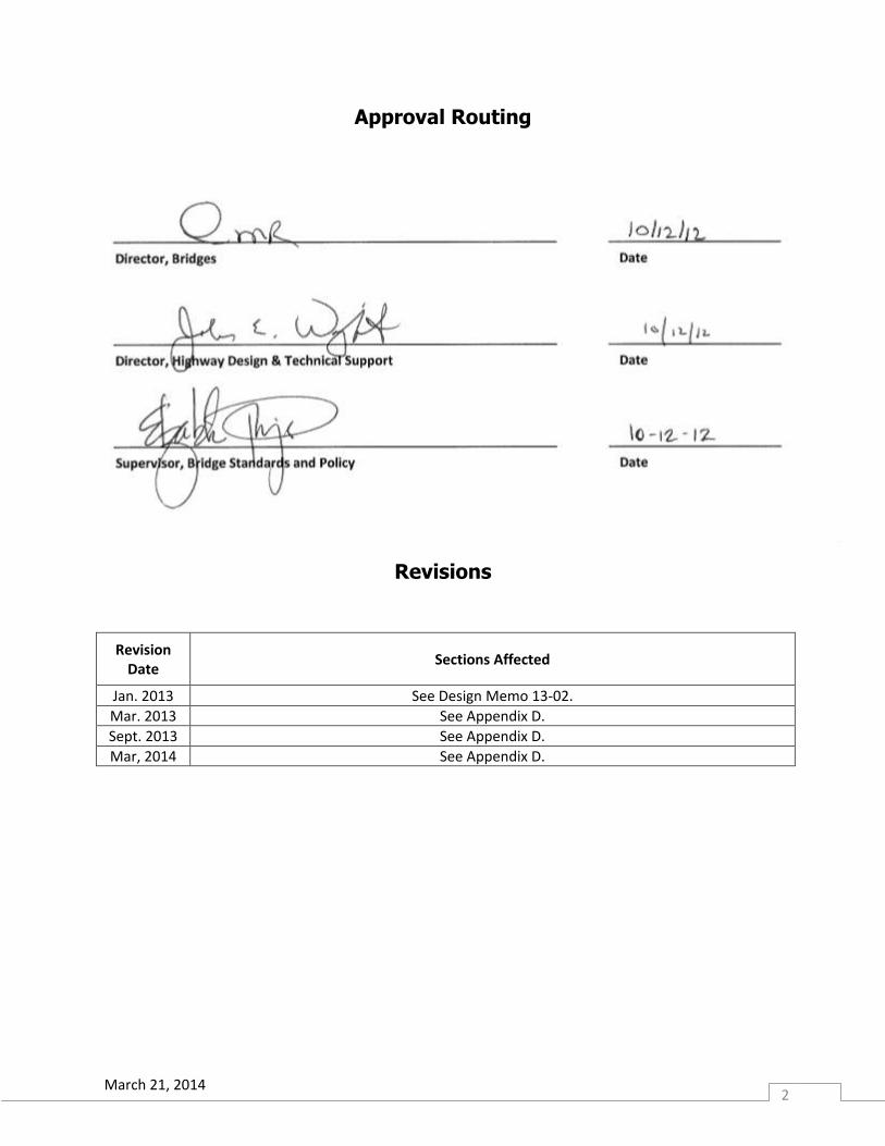
Approval Routing
Revisions
Revision Date
Sections Affected
Jan. 2013 See Design Memo 13-02.
Mar. 2013 See Appendix D.
Sept. 2013 See Appendix D.
Mar, 2014 See Appendix D.
March 21, 2014 3
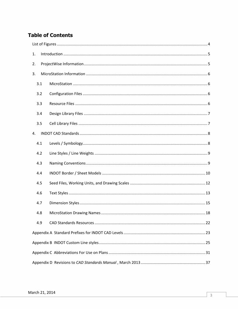
Table of Contents
List of Figures ............................................................................................................................................ 4
1. Introduction ...................................................................................................................................... 5
2. ProjectWise Information ................................................................................................................... 5
3. MicroStation Information ................................................................................................................. 6
3.1 MicroStation ............................................................................................................................. 6
3.2 Configuration Files .................................................................................................................... 6
3.3 Resource Files ........................................................................................................................... 6
3.4 Design Library Files ................................................................................................................... 7
3.5 Cell Library Files ........................................................................................................................ 7
4. INDOT CAD Standards ....................................................................................................................... 8
4.1 Levels / Symbology.................................................................................................................... 8
4.2 Line Styles / Line Weights ......................................................................................................... 9
4.3 Naming Conventions ................................................................................................................. 9
4.4 INDOT Border / Sheet Models ................................................................................................ 10
4.5 Seed Files, Working Units, and Drawing Scales ...................................................................... 12
4.6 Text Styles ............................................................................................................................... 13
4.7 Dimension Styles ..................................................................................................................... 15
4.8 MicroStation Drawing Names ................................................................................................. 18
4.9 CAD Standards Resources ....................................................................................................... 22
Appendix A Standard Prefixes for INDOT CAD Levels ............................................................................ 23
Appendix B INDOT Custom Line styles ................................................................................................... 25
Appendix C Abbreviations For Use on Plans .......................................................................................... 31
Appendix D Revisions to CAD Standards Manual , March 2013 ............................................................ 37
March 21, 2014 4
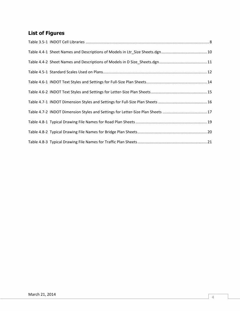
List of Figures
Table 3.5-1 INDOT Cell Libraries .................................................................................................................. 8
Table 4.4-1 Sheet Names and Descriptions of Models in Ltr_Size Sheets.dgn .......................................... 10
Table 4.4-2 Sheet Names and Descriptions of Models in D Size_Sheets.dgn ............................................ 11
Table 4.5-1 Standard Scales Used on Plans ................................................................................................ 12
Table 4.6-1 INDOT Text Styles and Settings for Full-Size Plan Sheets ........................................................ 14
Table 4.6-2 INDOT Text Styles and Settings for Letter-Size Plan Sheets .................................................... 15
Table 4.7-1 INDOT Dimension Styles and Settings for Full-Size Plan Sheets ............................................. 16
Table 4.7-2 INDOT Dimension Styles and Settings for Letter-Size Plan Sheets ......................................... 17
Table 4.8-1 Typical Drawing File Names for Road Plan Sheets .................................................................. 19
Table 4.8-2 Typical Drawing File Names for Bridge Plan Sheets ................................................................ 20
Table 4.8-3 Typical Drawing File Names for Traffic Plan Sheets ................................................................ 21
March 21, 2014 5
1. Introduction
The guidelines presented within this document provide information regarding the preparation and final
appearance of plans produced for INDOT road, bridge, and traffic projects using Bentley’s MicroStation
and InRoads software programs. It is intended to be used as a guide and reference for CAD users in an
attempt to attain a high level of consistency among plans. It is not intended to be a “how-to” guide for
using these software packages. Throughout this document, it is assumed that the user has a working
knowledge of the software and has some experience using it to produce the engineering drawings
required for a complete set of construction plans.
Direction to implement the guidelines presented in this document should not be construed as a
requirement to use a specific drafting platform. The deliverable required by INDOT continues to be the
PDF. Requirements for an electronic deliverable (.dgn, .dtm, etc.) and implementation of the CAD
standards associated with an electronic deliverable have not been determined. They are presented in
this document to facilitate future implementation.
Users should also be aware that requirements related to the content of INDOT plans are available in the
current Indiana Design Manual, and that document will govern in the event of conflicting information
presented in this CAD Standards Manual.
For current versions of the user files mentioned throughout this guide, as well as additional information,
please browse to the INDOT CAD Support website (http://in.gov/indot/3084.htm). For best results, it is
highly recommended that users work in the same versions or newer of the CAD software as is currently
installed on the INDOT system. Information regarding currently installed versions is available on the
Current Versions webpage (http://www.in.gov/indot/3088.htm).
2. ProjectWise Information
INDOT has chosen Bentley ProjectWise for its project management software program. All in-house
design projects reside in the secure managed ProjectWise environment. Information regarding
navigation in ProjectWise is available in the following documents:
DOTWise--INDOT Plans Production and Survey Guide, available for download on the CAD Support web
site in the Documents section.
DOTWise--INDOT Plans Production and Survey Guide, available in ProjectWise.
DOTWise Project Creator Quick Start Guide—ITAP and Project Creator Interface, available in ProjectWise.
Throughout this manual, links are provided to resource files residing in the ProjectWise environment as
well as on the World Wide Web for users not currently operating within the ProjectWise environment.
For information regarding ProjectWise and to apply for an account, users should contact CAD Support.
March 21, 2014 6
3. MicroStation Information
3.1 MicroStation
INDOT has selected MicroStation and InRoads for its Department-wide computer-aided drafting and
design package used to generate most contract plans. This document provides the Department’s CAD
resources and expectation for plan development (e.g., cell library, levels, and text styles). Consistently
using the established set of levels, styles, and reference files will allow various users within the
Department to work on the same set of plans without interfering with each other’s design work. By
integrating or linking MicroStation with other software packages (e.g., InRoads, SignCAD, and various
external databases), the designer can complete the design and layout of a project as well as calculate
the quantities necessary to produce a complete set of construction plans. For specific information
related to InRoads, please refer to the DOTWise--INDOT Plans Production and Survey Guide document
mentioned previously.
3.2 Configuration Files
CAD Support at INDOT has created a CAD environment (for use with MicroStation and InRoads) which
contains a basic configuration along with necessary resource files for the preparation of roadway and
structure plans. This environment is available to users for download at CAD Support V8i Downloads. All
necessary files may be downloaded and installed as separate items in order to accommodate different
networking configurations outside of INDOT.
When beginning any project the designer/drafter is responsible for verifying that the latest configuration files, resource files, design libraries, and cell libraries are installed on their systems.
3.3 Resource Files
It is the intent, at INDOT, to keep the resource files, including .pcf and standard configuration files, that
come packaged with MicroStation, InRoads, DesCartes, etc… , as close to “out of the box” as possible.
This is done in order to make implementation of INDOT’s CAD Standards as straightforward as possible.
INDOT CAD resource files are available on the CAD Support V8i Downloads web page, along with their
related configuration variable information. Those files necessary for preparation of INDOT production
plans are as follows:
Seed files: Contain initial configuration, including appropriate working units for INDOT drawing
files. See section 4.5 for available seed files and settings.
IN_Units.def: Units definition files for selecting the proper working units.
IN_Sheetsizes.def: Definition file containing the settings for recommended sheet model sizes.
March 21, 2014 7
Design library files:
o IN_Symbology.dgnlib: Contains all level symbology including line styles as well as all text
and dimension styles used in the INDOT environment. See section 4.1 for level
definitions and section 4.2 for custom line styles. See sections 4.6 and 4.7 for text and
dimension styles.
Template drawing files: Contain borders used on INDOT plan sheets. See section 4.4 for more
information.
Cell library files: Contain cells to be inserted into INDOT base files and plan sheet files. See
section 3.5 for cell libraries available.
Plotting files: Contain pen tables, design scripts, and settings files for use with the ProjectWise
InterPlot Organizer.
InRoads resource files: Contain the INDOT-configured .xin file and borders required for use with
InRoads Plan and Profile Generator and Cross Section creation tools.
3.4 Design Library Files
Design library (.dgnlib) files are files containing predefined settings for key design elements, including
text styles, dimension styles, layers, custom line styles, etc. When an element is placed in a design file,
MicroStation accesses the .dgnlib file for that element’s predefined properties or settings. Once placed,
these elements become part of the active design file. If changes are later made to the .dgnlib file, those
changes are not automatically updated in the drawing file. All or part of the settings can be updated
from a revised .dgnlib file by executing the key-in command “dgnlib update (all, dimstyles, levels, etc.)”.
It is also possible to update settings for individual elements (text styles, dimension styles, levels, etc.) by
opening up each element’s Settings toolbox and choosing Update from Library from the appropriate
menu.
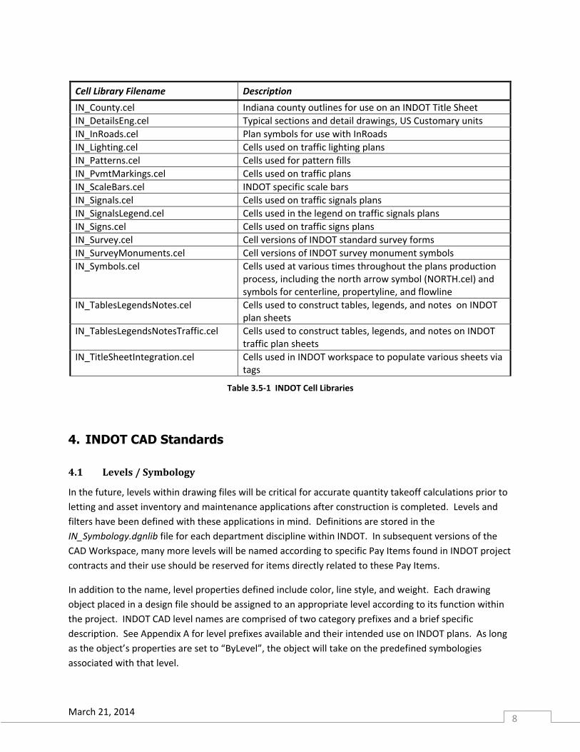
3.5 Cell Library Files
Currently there are several cell libraries available for use in the preparation of INDOT plans. The current
cell libraries are located in DOTWise\Documents\INDOTWorkspace\Managed\Workspace\Standards\
cell\ in ProjectWise. They, along with a catalog of cells, are available from CAD Support V8i
Downloads/Cell Libraries. See Table 3.5-1 for descriptions of INDOT cell libraries available.
March 21, 2014 8
Cell Library Filename Description
IN_County.cel Indiana county outlines for use on an INDOT Title Sheet
IN_DetailsEng.cel Typical sections and detail drawings, US Customary units
IN_InRoads.cel Plan symbols for use with InRoads
IN_Lighting.cel Cells used on traffic lighting plans
IN_Patterns.cel Cells used for pattern fills
IN_PvmtMarkings.cel Cells used on traffic plans
IN_ScaleBars.cel INDOT specific scale bars
IN_Signals.cel Cells used on traffic signals plans
IN_SignalsLegend.cel Cells used in the legend on traffic signals plans
IN_Signs.cel Cells used on traffic signs plans
IN_Survey.cel Cell versions of INDOT standard survey forms
IN_SurveyMonuments.cel Cell versions of INDOT survey monument symbols
IN_Symbols.cel Cells used at various times throughout the plans production process, including the north arrow symbol (NORTH.cel) and symbols for centerline, propertyline, and flowline
IN_TablesLegendsNotes.cel Cells used to construct tables, legends, and notes on INDOT plan sheets
IN_TablesLegendsNotesTraffic.cel Cells used to construct tables, legends, and notes on INDOT traffic plan sheets
IN_TitleSheetIntegration.cel Cells used in INDOT workspace to populate various sheets via tags
Table 3.5-1 INDOT Cell Libraries
4. INDOT CAD Standards
4.1 Levels / Symbology
In the future, levels within drawing files will be critical for accurate quantity takeoff calculations prior to
letting and asset inventory and maintenance applications after construction is completed. Levels and
filters have been defined with these applications in mind. Definitions are stored in the
IN_Symbology.dgnlib file for each department discipline within INDOT. In subsequent versions of the
CAD Workspace, many more levels will be named according to specific Pay Items found in INDOT project
contracts and their use should be reserved for items directly related to these Pay Items.
In addition to the name, level properties defined include color, line style, and weight. Each drawing
object placed in a design file should be assigned to an appropriate level according to its function within
the project. INDOT CAD level names are comprised of two category prefixes and a brief specific
description. See Appendix A for level prefixes available and their intended use on INDOT plans. As long
as the object’s properties are set to “ByLevel”, the object will take on the predefined symbologies
associated with that level.
March 21, 2014 9
In order to assist the user in narrowing his/her focus to a particular discipline or type of plan sheet, a
number of Filter Groups have also been defined. The Filter tool, located on the Attributes toolbar,
allows users to define the group of levels viewed within the Level Manager or Level Display dialogs.
For most projects, the levels defined in the design library file will suffice throughout the plan
preparation process. There will, however, likely still be unique situations that may require levels that do
not already exist. For these situations, users should follow the naming conventions established in
Appendix A.
4.2 Line Styles / Line Weights
Various line styles and weights are typically used to differentiate between elements of objects and to
focus attention on key elements within a drawing. Regardless of the line style or weight chosen, all
elements must be clearly visible and text must be easily read when the drawing is printed at its full size
as well as when it is scaled for smaller printed formats. Users are discouraged from using line styles
numbered 1-7 in design models, as their behavior is somewhat unpredictable on printed plans. Bentley
recommends that users assign custom line styles to objects for more control of their appearance.
Consequently INDOT has defined a number of custom line styles for use on INDOT plans. These
definitions are also stored in IN_Symbology.dgnlib. See Appendix B for samples of INDOT custom line
styles along with their intended uses. The appearance of lines on plans must be consistent with these
samples.
In general, existing features should be shown using dashed lines or other appropriate line styles as
shown in Appendix B. INDOT’s preference is that existing features are screened back or grayed out so
that they appear lighter than proposed work and are still clearly visible on half-size plots.
Users are discouraged from defining their own custom line styles. In the event that a new line style is
needed, users should contact CAD Support for assistance.
4.3 Naming Conventions
The following prefixes shall be used when naming models and cells related to the various disciplines.
File and level naming conventions differ slightly from these. See section 4.1 for level naming
conventions and section 4.8 for file naming conventions.
Bridges BR_ Signs and Lighting SL_
Design DS_ Signs SN_
Lighting LG_ Standards ST_
Planning PL_ Survey SV_
Road RD_ Traffic TR_
Signals SG_ Pavement Marking PM_
March 21, 2014 10
4.4 INDOT Border / Sheet Models
A series of template sheet models has been developed for use when preparing INDOT Plans. Each of
these sheet models contains the required INDOT sheet border, as well as additional pre-formatted text
and commonly used symbols. These sheet models are designed to be imported into the working dgn
file with a scale factor of 1.0 and placed at the origin (0, 0). The user should then edit text as needed
and delete any items not needed. See the Indiana Design Manual (IDM) section 14-3.03 for appropriate
sizing of plan sheets. Users should also be aware that unless they are operating within the INDOT
ProjectWise managed workspace, some extra information may be visible and a certain amount of
specialized functionality set up for these sheets may be diminished. Table 4.4-1 and Table 4.4-2 list the
sheet models available from the following files located in the DOTWise\Documents\Template
Documents\DGN\ folder in ProjectWise or downloaded from CAD Support V8i Downloads/Sheet Files.
Ltr_sheets.dgn: For use with projects using letter size (8.5” x 11”) paper.
D Size_sheets.dgn: For use with projects using full-size paper. The border sheets provided in
this file have been formatted for use on “D” size (24” x 36”) or 22” x 34” paper. No scaling is
necessary for 22” x 34” paper, although users should be careful to position the frame
appropriately.
In general, a north arrow should be placed on every plan view. Where it is needed but not already
provided, the north arrow symbol (NORTH from the IN_Symbols.cel library file) should be inserted on a
sheet model. The north arrow should appear the same size on all full-size sheets on which it is placed,
and should be approximately 2 ½ in. from arrowhead tip to tail. Placing NORTH.cel using a scale of 1.0
will result in the correct sizing of the symbol. When placed on 8 ½” x 11” sheets, NORTH.cel should be
scaled by 0.5.
Name Description
Ltr. Detail 8.5” x 11” Detail Border – Portrait
Ltr. Detour Sheet Signing 8.5” x 11” Recommended Detour Signing Sheet
Ltr. Landscape Detail 8.5” x 11” Detail Border – Landscape
Ltr. Strip Map Sheet 8.5” x 11” Strip Map Sheet
Ltr. Title Sheet 8.5” x 11” Title Sheet
Table 4.4-1 Sheet Names and Descriptions of Models in Ltr_Size Sheets.dgn
March 21, 2014 11
Name Description/Intended Use
BR_Detail Sheet Detail Sheet for bridge plans—used for structure details, traffic maintenance details, soil borings, layout, general plan, approach details, and plan and profile sheets
BR_Index Sheet Bridge Plan Index Sheet
BR_Soil Boring Sheet Soil Boring Sheet—used for bridge plans
BR_Summary Sheet Bridge Plan Bridge Summary Sheet
BR_Title Sheet Bridge Plan Title Sheet
BR_Title Sheet Rehab Bridge Rehab Plan Title Sheet
BR_Title Sheet ROW Bridge Right-Of-Way Plan Title Sheet
LG_Highway Data Sheet Lighting Plan Highway Data Sheet—used on road plans, bridge plans, and separate lighting plans)
LG_Index Sheet Lighting Plan Index and General Notes Sheet
PL_Layout Sheet Planning Layout Sheet
RD_Detail Sheet Detail Sheet for road plans—used for roadway details, traffic maintenance details, and plan and profile sheets.
RD_Index Sheet Road Plan Index and General Notes Sheet
RD_Pavement Marking Sheet Pavement Marking Sheet—used for traffic-work details on road plans and bridge plans
RD_Pipe Material Sheet Pipe Material Sheet—used for road plans and bridge plans
RD_Plat Sheet Plat Sheet—used for survey route sheets on road plans
RD_Summary Sheet Road Summary Sheet—used for road plans and bridge plans
RD_Title Sheet Road Plan Title Sheet
RD_Title Sheet ROW Road Right-Of-Way Plan Title Sheet
SG_Detail Sheet Detail Sheet—used for plan and detail sheets on signalization plans
SG_Title Sheet Signals Plan Title Sheet
SL_Plan Sheet Plan Sheet—used for lighting and signing plan, layout, and details on traffic-signs plans, lighting plans, road plans, and bridge plans
SL_Title Sheet Signs and Lighting Plan Title Sheet
SN_Index Sheet Signs Plan Index and General Notes Sheet
SN_Panel Sign and Post Summary Sheet
Sign and Post Summary Sheet—used for panel-sign information on traffic-signs plans, road plans, and bridge plans
SN_Sheet Sign and Post Summary Sheet
Sign and Post Summary Sheet—used for sheet-sign information on traffic-signs plans, road plans, and bridge plans
Table 4.4-2 Sheet Names and Descriptions of Models in D Size_Sheets.dgn
March 21, 2014 12
4.5 Seed Files, Working Units, and Drawing Scales
The working units and a global origin have been defined in each seed file according to its intended use.
The Department has set the global origin to x=0, y=0 and z=0 in all of the INDOT seed files. The
following drawing seed files are available for download from CAD Support V8i Downloads and are
located in DOTWise\Documents\Template Documents\Seed\MicroStation\ in ProjectWise. Users are
expected to use the seed file appropriate for their specific application. Users should also note that these
seed files are slightly different from those provided specifically for use with InRoads.
INDOT_US_SVFT_Seed.dgn: Used for base drawing files, details, and exhibits using US
Customary units. Working Units are set to Survey Feet (‘) and Inches (“).
INDOT_US_seed.dgn: Used for drawing files and detail drawings using US Customary units.
Working Units are set to Feet (‘) and Inches (“).
INDOT_SI_seed.dgn: Only used for legacy projects using SI units. Working Units are set to
Meters (m) and Millimeters (mm).
All objects shall be drawn at actual size in the design model. Scaling should only be applied when the
model is referenced into the sheet model. This reference scale then determines the annotation scale to
be used for the referenced design model. See Table 4.5-1 for the standard scales allowed on INDOT
plans. See IDM section 14-3.05 for recommended drawing scales to be used on each type of plan sheet.
Drawing Scale (Anno. Scale)
True Scale (Ref. Scale)
Drawing Scale (Anno. Scale)
True Scale (Ref. Scale)
1/32 in. = 1 ft 1 : 384 1 in. = 5 ft 1 : 60
1/16 in. = 1 ft 1 : 192 1 in. = 10 ft 1 : 120
3/32 in. = 1 ft 1 : 128 1 in. = 20 ft 1 : 240
1/8 in. = 1 ft 1 : 96 1 in. = 30 ft 1 : 360
3/16 in. = 1 ft 1 : 64 1 in. = 40 ft 1 : 480
1/4 in. = 1 ft 1 : 48 1 in. = 50 ft 1 : 600
3/8 in. = 1 ft 1 : 32 1 in. = 60 ft 1 : 720
1/2 in. = 1 ft 1 : 24 1 in. = 100 ft 1 : 1200
3/4 in. = 1 ft 1 : 16 1 in. = 200 ft 1 : 2400
1 in. = 1 ft 1 : 12 1 in. = 300 ft 1 : 3600
1 1/2 in. = 1 ft 1 : 8 1 in. = 400 ft 1 : 4800
3 in. = 1 ft 1 : 4 1 in. = 500 ft 1 : 6000
6 in. = 1 ft 1 : 2 1 in. = 600 ft 1 : 7200
12 in. = 1 ft 1 : 1 1 in. = 1000 ft 1 : 12000
1 in. = 2000 ft 1 : 24000
Table 4.5-1 Standard Scales Used on Plans
March 21, 2014 13
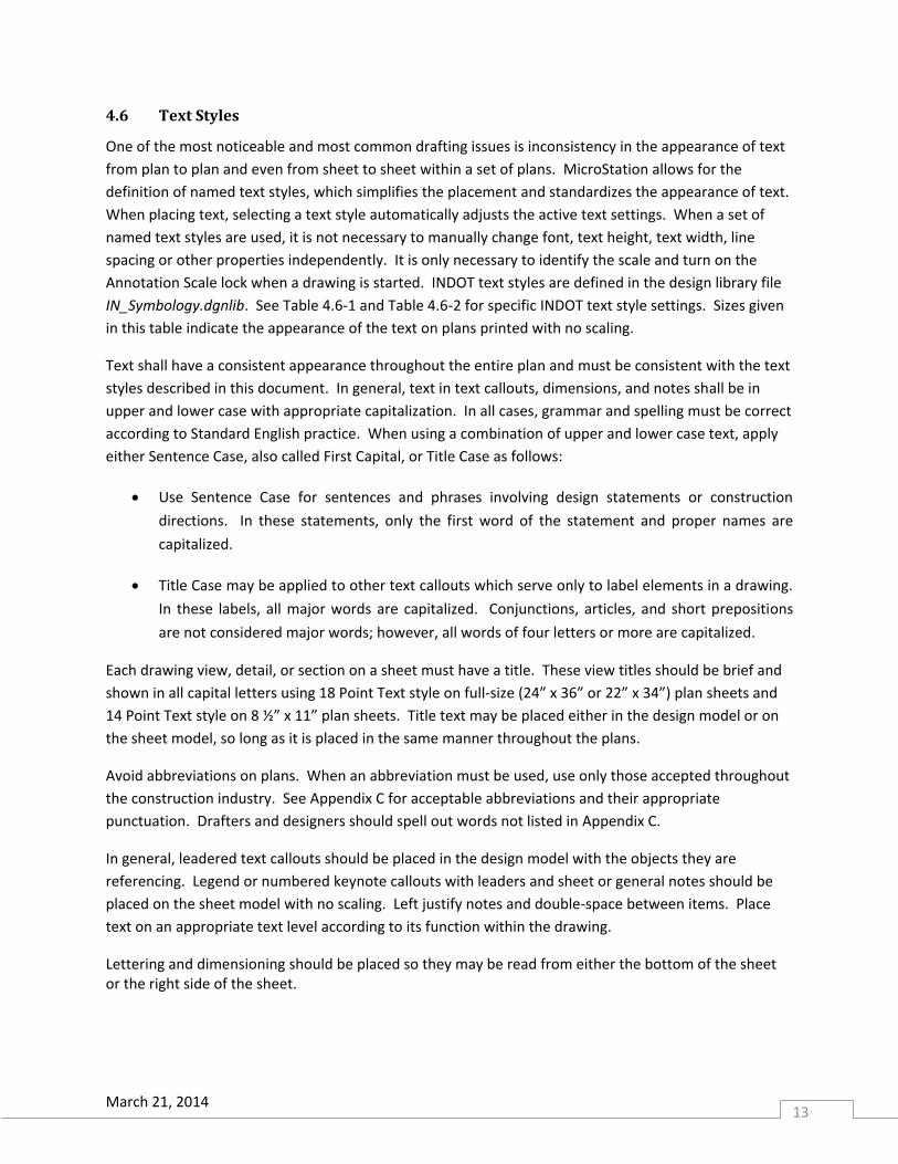
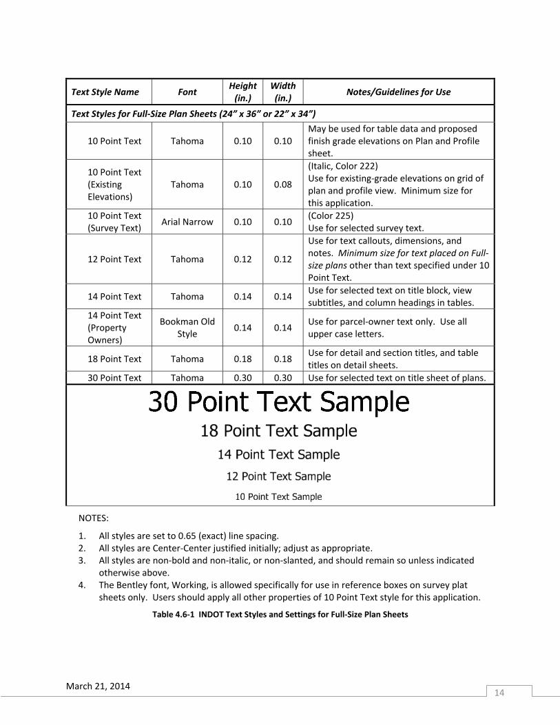
4.6 Text Styles
One of the most noticeable and most common drafting issues is inconsistency in the appearance of text
from plan to plan and even from sheet to sheet within a set of plans. MicroStation allows for the
definition of named text styles, which simplifies the placement and standardizes the appearance of text.
When placing text, selecting a text style automatically adjusts the active text settings. When a set of
named text styles are used, it is not necessary to manually change font, text height, text width, line
spacing or other properties independently. It is only necessary to identify the scale and turn on the
Annotation Scale lock when a drawing is started. INDOT text styles are defined in the design library file
IN_Symbology.dgnlib. See Table 4.6-1 and Table 4.6-2 for specific INDOT text style settings. Sizes given
in this table indicate the appearance of the text on plans printed with no scaling.
Text shall have a consistent appearance throughout the entire plan and must be consistent with the text
styles described in this document. In general, text in text callouts, dimensions, and notes shall be in
upper and lower case with appropriate capitalization. In all cases, grammar and spelling must be correct
according to Standard English practice. When using a combination of upper and lower case text, apply
either Sentence Case, also called First Capital, or Title Case as follows:
Use Sentence Case for sentences and phrases involving design statements or construction
directions. In these statements, only the first word of the statement and proper names are
capitalized.
Title Case may be applied to other text callouts which serve only to label elements in a drawing.
In these labels, all major words are capitalized. Conjunctions, articles, and short prepositions
are not considered major words; however, all words of four letters or more are capitalized.
Each drawing view, detail, or section on a sheet must have a title. These view titles should be brief and
shown in all capital letters using 18 Point Text style on full-size (24” x 36” or 22” x 34”) plan sheets and
14 Point Text style on 8 ½” x 11” plan sheets. Title text may be placed either in the design model or on
the sheet model, so long as it is placed in the same manner throughout the plans.
Avoid abbreviations on plans. When an abbreviation must be used, use only those accepted throughout
the construction industry. See Appendix C for acceptable abbreviations and their appropriate
punctuation. Drafters and designers should spell out words not listed in Appendix C.
In general, leadered text callouts should be placed in the design model with the objects they are
referencing. Legend or numbered keynote callouts with leaders and sheet or general notes should be
placed on the sheet model with no scaling. Left justify notes and double-space between items. Place
text on an appropriate text level according to its function within the drawing.
Lettering and dimensioning should be placed so they may be read from either the bottom of the sheet or the right side of the sheet.
March 21, 2014 14
Text Style Name Font Height(in.)
Width (in.)
Notes/Guidelines for Use
Text Styles for Full‐Size Plan Sheets (24” x 36” or 22” x 34”)
10 Point Text Tahoma 0.10 0.10 May be used for table data and proposed finish grade elevations on Plan and Profile sheet.
10 Point Text (Existing Elevations)
Tahoma 0.10 0.08
(Italic, Color 222) Use for existing‐grade elevations on grid of plan and profile view. Minimum size for this application.
10 Point Text (Survey Text)
Arial Narrow 0.10 0.10 (Color 225) Use for selected survey text.
12 Point Text Tahoma 0.12 0.12
Use for text callouts, dimensions, and notes. Minimum size for text placed on Full‐size plans other than text specified under 10 Point Text.
14 Point Text Tahoma 0.14 0.14 Use for selected text on title block, view subtitles, and column headings in tables.
14 Point Text (Property Owners)
Bookman Old Style
0.14 0.14 Use for parcel‐owner text only. Use all upper case letters.
18 Point Text Tahoma 0.18 0.18 Use for detail and section titles, and table titles on detail sheets.
30 Point Text Tahoma 0.30 0.30 Use for selected text on title sheet of plans.
NOTES:
1. All styles are set to 0.65 (exact) line spacing. 2. All styles are Center‐Center justified initially; adjust as appropriate. 3. All styles are non‐bold and non‐italic, or non‐slanted, and should remain so unless indicated
otherwise above. 4. The Bentley font, Working, is allowed specifically for use in reference boxes on survey plat
sheets only. Users should apply all other properties of 10 Point Text style for this application.
Table 4.6‐1 INDOT Text Styles and Settings for Full‐Size Plan Sheets
March 21, 2014 15
Text Style Name Font Height(in.)
Width (in.)
Notes/Guidelines for Use
Text Styles for Letter‐Size Plan Sheets (8 ½” x 11”)
6 Point Text Tahoma 0.06 0.06 May be used for table data, existing‐grade elevations on grid of plan and profile view, and selected survey text.
7 Point Text Tahoma 0.07 0.07 Use for selected text on title block., column headings in tables, and parcel‐owner text.
7 Point Text (Survey Text)
Arial Narrow 0.07 0.07 (Color 222) Use for selected survey text.
9 Point Text Tahoma 0.09 0.09
Use for text callouts, dimensions, notes, column headings in tables, and parcel‐owner text. Minimum size for all text placed on letter‐size plans, other than text specified under 6 Point Text.
12 Point Text Tahoma 0.12 0.12 Use for selected text on title sheet of plans.
14 Point Text Tahoma 0.14 0.14 Use for detail and section titles, and table titles on detail sheets.
NOTES:
1. All styles are set to 0.65 (exact) line spacing. 2. All styles are Center‐Center justified initially; adjust as appropriate. 3. All styles are non‐bold and non‐italic, or non‐slanted, and should remain so unless indicated
otherwise above.
Table 4.6‐2 INDOT Text Styles and Settings for Letter‐Size Plan Sheets
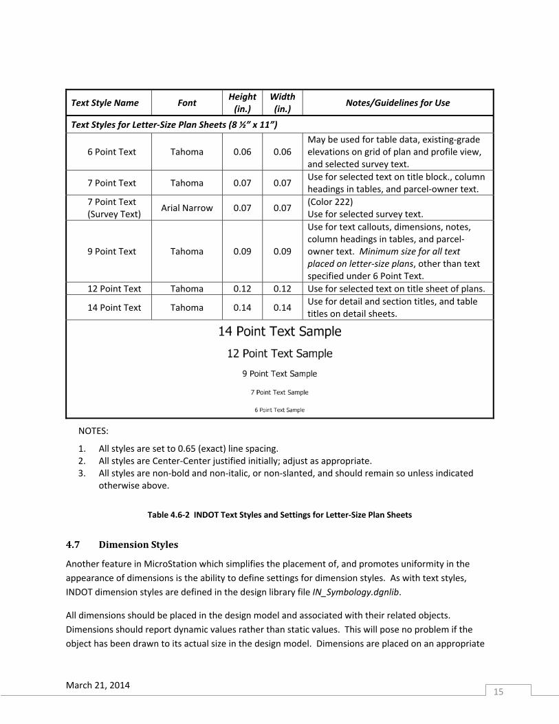
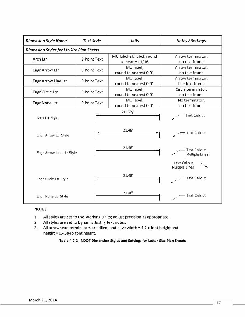
4.7 DimensionStyles
Another feature in MicroStation which simplifies the placement of, and promotes uniformity in the
appearance of dimensions is the ability to define settings for dimension styles. As with text styles,
INDOT dimension styles are defined in the design library file IN_Symbology.dgnlib.
All dimensions should be placed in the design model and associated with their related objects.
Dimensions should report dynamic values rather than static values. This will pose no problem if the
object has been drawn to its actual size in the design model. Dimensions are placed on an appropriate
March 21, 2014 16
text/dimension level when they are placed using the INDOT dimension styles. See Table 4.7‐1 and Table
4.7‐2 for the dimension styles that are provided for use on INDOT plans. Dimensions and notes placed
on full‐size (24” x 36” or 22” x 34”) plan sheets shall utilize 12 Point Text style , whereas those placed on
letter‐size plan sheets shall utilize 9 Point Text style. Their appearance must be consistent with the
styles described in Tables 4.7‐1 and Table 4.7‐2.
Dimension Style Name Text Style Units Notes / Settings
Dimension Styles for D‐Size Plan Sheets
Arch 12 Point Text MU label‐SU label,
round to nearest 1/16 Arrow terminator, no text frame
Engr Arrow 12 Point Text MU label,
round to nearest 0.01 Arrow terminator, no text frame
Engr Arrow Line 12 Point Text MU label,
round to nearest 0.01 Arrow terminator, line text frame
Engr Circle 12 Point Text MU label,
round to nearest 0.01 Circle terminator, no text frame
Engr None 12 Point Text MU label,
round to nearest 0.01 No terminator, no text frame
NOTES:
1. All styles are set to use Working Units; adjust precision as appropriate. 2. All styles are set to Dynamic Justify text notes. 3. All arrowhead terminators are filled, and have width = 1.2 x font height and
height = 0.4584 x font height.
Table 4.7‐1 INDOT Dimension Styles and Settings for Full‐Size Plan Sheets
March 21, 2014 17
Dimension Style Name Text Style Units Notes / Settings
Dimension Styles for Ltr‐Size Plan Sheets
Arch Ltr 9 Point Text MU label‐SU label, round
to nearest 1/16 Arrow terminator, no text frame
Engr Arrow Ltr 9 Point Text MU label,
round to nearest 0.01 Arrow terminator, no text frame
Engr Arrow Line Ltr 9 Point Text MU label,
round to nearest 0.01 Arrow terminator, line text frame
Engr Circle Ltr 9 Point Text MU label,
round to nearest 0.01 Circle terminator, no text frame
Engr None Ltr 9 Point Text MU label,
round to nearest 0.01 No terminator, no text frame
NOTES:
1. All styles are set to use Working Units; adjust precision as appropriate. 2. All styles are set to Dynamic Justify text notes. 3. All arrowhead terminators are filled, and have width = 1.2 x font height and
height = 0.4584 x font height.
Table 4.7‐2 INDOT Dimension Styles and Settings for Letter‐Size Plan Sheets
March 21, 2014 18
All dimensioning should be performed using US Customary units. The accuracy of plan dimensions
should be consistent with data upon which they are based. See IDM 14-3.06 for guidance regarding
accuracy of dimensions for various elements.
In general, use the unit method of feet and inches on all plans unless the unit method of decimals is
called for below. Feet and inches may be shown either with unit abbreviations (4 ft 3 in.) or with
punctuation (4’-3”), as long as they are shown as such consistently throughout the plans. When using
unit abbreviations, provide a space between the value and the abbreviation. When using punctuation
units, there should be a hyphen to separate the major and minor units, and no spaces in the dimension.
The Arch dimension styles defined in the design library utilize punctuation according to these
conventions.
The unit method of decimals (decimal-feet) should be used for the following:
stations
elevations
percent grades
areas
latitude and longitude
curve data
length of project where called out in miles
When using the unit method of decimals, use either unit abbreviations (e.g. 75.42 ft) or punctuation
(e.g. 75.42’) as long as their use is consistent throughout the plans. As with the method of feet and
inches, when using unit abbreviations, provide a space between the value and the abbreviation. When
using punctuation units, there should be no space in the dimension. In addition, for a value less than 1,
place a zero before the decimal point for clarity (e.g. 0.72 ft). The Engr dimension styles in the design
library have been defined to use unit punctuation.
When a leader is necessary to connect dimension text to its extension lines or to attach a text note to an
element, use a segmented line rather than a curved or spline leader along with an appropriate
terminator. All arrowhead terminators should be filled and clearly visible on the plans.
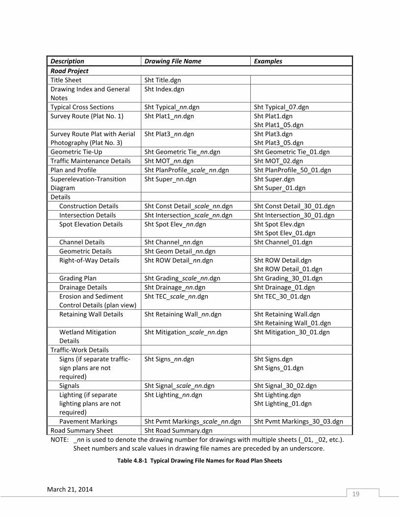
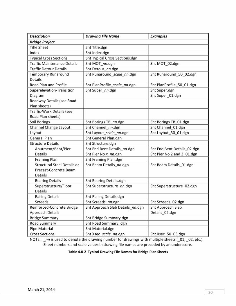
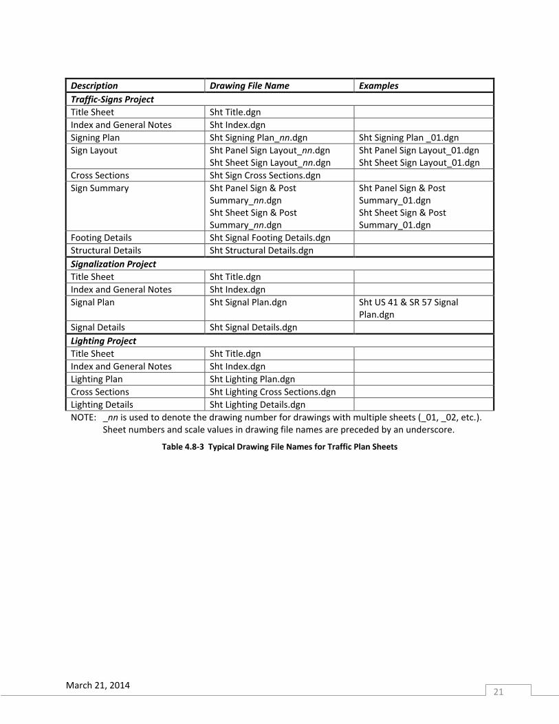
4.8 MicroStation Drawing Names
The use of standard plan sheet names can eliminate numerous common problems. See Table 4.8-1
through Table 4.8-3 for names of typical drawing files created in MicroStation. For a complete
discussion of the naming of base drawings and plan sheet drawing files created in InRoads, see the
DOTWise document on the CAD Support web site or in ProjectWise. See IDM section 14-3.07 for
guidelines concerning the organization of plans sheets for various projects.
March 21, 2014 19
Description Drawing File Name Examples
Road Project
Title Sheet Sht Title.dgn
Drawing Index and General Notes
Sht Index.dgn
Typical Cross Sections Sht Typical_nn.dgn Sht Typical_07.dgn
Survey Route (Plat No. 1) Sht Plat1_nn.dgn Sht Plat1.dgn Sht Plat1_05.dgn
Survey Route Plat with Aerial Photography (Plat No. 3)
Sht Plat3_nn.dgn Sht Plat3.dgn Sht Plat3_05.dgn
Geometric Tie-Up Sht Geometric Tie_nn.dgn Sht Geometric Tie_01.dgn
Traffic Maintenance Details Sht MOT_nn.dgn Sht MOT_02.dgn
Plan and Profile Sht PlanProfile_scale_nn.dgn Sht PlanProfile_50_01.dgn
Superelevation-Transition Diagram
Sht Super_nn.dgn Sht Super.dgn Sht Super_01.dgn
Details
Construction Details Sht Const Detail_scale_nn.dgn Sht Const Detail_30_01.dgn
Intersection Details Sht Intersection_scale_nn.dgn Sht Intersection_30_01.dgn
Spot Elevation Details Sht Spot Elev_nn.dgn Sht Spot Elev.dgn Sht Spot Elev_01.dgn
Channel Details Sht Channel_nn.dgn Sht Channel_01.dgn
Geometric Details Sht Geom Detail_nn.dgn
Right-of-Way Details Sht ROW Detail_nn.dgn Sht ROW Detail.dgn Sht ROW Detail_01.dgn
Grading Plan Sht Grading_scale_nn.dgn Sht Grading_30_01.dgn
Drainage Details Sht Drainage_nn.dgn Sht Drainage_01.dgn
Erosion and Sediment Control Details (plan view)
Sht TEC_scale_nn.dgn Sht TEC_30_01.dgn
Retaining Wall Details Sht Retaining Wall_nn.dgn Sht Retaining Wall.dgn Sht Retaining Wall_01.dgn
Wetland Mitigation Details
Sht Mitigation_scale_nn.dgn Sht Mitigation_30_01.dgn
Traffic-Work Details
Signs (if separate traffic-sign plans are not required)
Sht Signs_nn.dgn Sht Signs.dgn Sht Signs_01.dgn
Signals Sht Signal_scale_nn.dgn Sht Signal_30_02.dgn
Lighting (if separate lighting plans are not required)
Sht Lighting_nn.dgn Sht Lighting.dgn Sht Lighting_01.dgn
Pavement Markings Sht Pvmt Markings_scale_nn.dgn Sht Pvmt Markings_30_03.dgn
Road Summary Sheet Sht Road Summary.dgn
NOTE: _nn is used to denote the drawing number for drawings with multiple sheets (_01, _02, etc.). Sheet numbers and scale values in drawing file names are preceded by an underscore.
Table 4.8-1 Typical Drawing File Names for Road Plan Sheets
March 21, 2014 20
Description Drawing File Name Examples
Bridge Project
Title Sheet Sht Title.dgn
Index Sht Index.dgn
Typical Cross Sections Sht Typical Cross Sections.dgn
Traffic Maintenance Details Sht MOT_nn.dgn Sht MOT_02.dgn
Traffic Detour Details Sht Detour_nn.dgn
Temporary Runaround Details
Sht Runaround_scale_nn.dgn
Sht Runaround_50_02.dgn
Road Plan and Profile Sht PlanProfile_scale_nn.dgn Sht PlanProfile_50_01.dgn
Superelevation‐Transition Diagram
Sht Super_nn.dgn Sht Super.dgn Sht Super_01.dgn
Roadway Details (see Road Plan sheets)
Traffic‐Work Details (see Road Plan sheets)
Soil Borings Sht Borings TB_nn.dgn Sht Borings TB_01.dgn
Channel Change Layout Sht Channel_nn.dgn Sht Channel_01.dgn
Layout Sht Layout_scale_nn.dgn Sht Layout_30_01.dgn
General Plan Sht General Plan.dgn
Structure Details Sht Structure.dgn
Abutment/Bent/Pier Details
Sht End Bent Details_nn.dgn Sht Pier No x_nn.dgn
Sht End Bent Details_02.dgn Sht Pier No 2 and 3_01.dgn
Framing Plan Sht Framing Plan.dgn
Structural Steel Details or Precast‐Concrete Beam Details
Sht Beam Details_nn.dgn Sht Beam Details_01.dgn
Bearing Details Sht Bearing Details.dgn
Superstructure/Floor Details
Sht Superstructure_nn.dgn Sht Superstructure_02.dgn
Railing Details Sht Railing Details.dgn
Screeds Sht Screeds_nn.dgn Sht Screeds_02.dgn
Reinforced‐Concrete Bridge Approach Details
Sht Approach Slab Details_nn.dgn Sht Approach Slab Details_02.dgn
Bridge Summary Sht Bridge Summary.dgn
Road Summary Sht Road Summary. dgn
Pipe Material Sht Material.dgn
Cross Sections Sht Xsec_scale_nn.dgn Sht Xsec_50_03.dgn
NOTE: _nn is used to denote the drawing number for drawings with multiple sheets (_01, _02, etc.). Sheet numbers and scale values in drawing file names are preceded by an underscore.
Table 4.8‐2 Typical Drawing File Names for Bridge Plan Sheets
March 21, 2014 21
Description Drawing File Name Examples
Traffic-Signs Project
Title Sheet Sht Title.dgn
Index and General Notes Sht Index.dgn
Signing Plan Sht Signing Plan_nn.dgn Sht Signing Plan _01.dgn
Sign Layout Sht Panel Sign Layout_nn.dgn Sht Sheet Sign Layout_nn.dgn
Sht Panel Sign Layout_01.dgn Sht Sheet Sign Layout_01.dgn
Cross Sections Sht Sign Cross Sections.dgn
Sign Summary Sht Panel Sign & Post Summary_nn.dgn Sht Sheet Sign & Post Summary_nn.dgn
Sht Panel Sign & Post Summary_01.dgn Sht Sheet Sign & Post Summary_01.dgn
Footing Details Sht Signal Footing Details.dgn
Structural Details Sht Structural Details.dgn
Signalization Project
Title Sheet Sht Title.dgn
Index and General Notes Sht Index.dgn
Signal Plan Sht Signal Plan.dgn Sht US 41 & SR 57 Signal Plan.dgn
Signal Details Sht Signal Details.dgn
Lighting Project
Title Sheet Sht Title.dgn
Index and General Notes Sht Index.dgn
Lighting Plan Sht Lighting Plan.dgn
Cross Sections Sht Lighting Cross Sections.dgn
Lighting Details Sht Lighting Details.dgn
NOTE: _nn is used to denote the drawing number for drawings with multiple sheets (_01, _02, etc.). Sheet numbers and scale values in drawing file names are preceded by an underscore.
Table 4.8-3 Typical Drawing File Names for Traffic Plan Sheets
March 21, 2014 22
4.9 CAD Standards Resources
When you have questions or need assistance:
INDOT CAD Support Email: [email protected] or through INDOT Sharepoint: http://sharepoint.indot.in.gov/cadsite/default.aspx Web site: http://in.gov/indot/3084.htm
CAD Support Publications:
DOTWise Project Creator, available in ProjectWise INDOT New User 2A, available in ProjectWise DOTWise--INDOT Plans Production and Survey Guide, available in ProjectWise DOTWise--INDOT Plans Production and Survey Guide, available for download from the CAD Support web site in the Documents section
Indiana Design Manual http://www.in.gov/indot/design_manual/index.htm INDOT Land & Aerial Survey Office Web site: http://www.in.gov/indot/2715.htm
Land & Aerial Survey Office Publications: Photogrammetric Mapping Specifications & Services Manual, available for download from the Land & Aerial Survey Office web site in the Manuals & Standard Links section
March 21, 2014 23
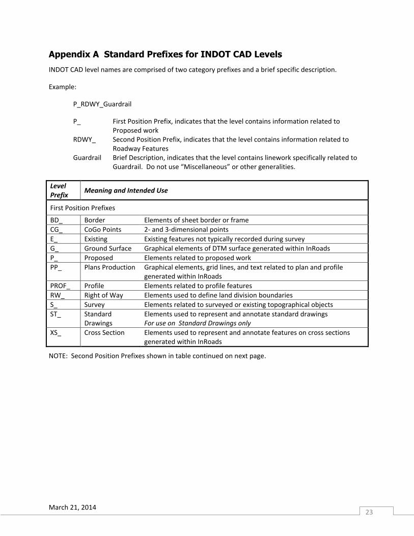
Appendix A Standard Prefixes for INDOT CAD Levels
INDOT CAD level names are comprised of two category prefixes and a brief specific description.
Example:
P_RDWY_Guardrail
P_ First Position Prefix, indicates that the level contains information related to Proposed work
RDWY_ Second Position Prefix, indicates that the level contains information related to Roadway Features
Guardrail Brief Description, indicates that the level contains linework specifically related to Guardrail. Do not use “Miscellaneous” or other generalities.
Level Prefix
Meaning and Intended Use
First Position Prefixes
BD_ Border Elements of sheet border or frame
CG_ CoGo Points 2- and 3-dimensional points
E_ Existing Existing features not typically recorded during survey
G_ Ground Surface Graphical elements of DTM surface generated within InRoads
P_ Proposed Elements related to proposed work
PP_ Plans Production Graphical elements, grid lines, and text related to plan and profile generated within InRoads
PROF_ Profile Elements related to profile features
RW_ Right of Way Elements used to define land division boundaries
S_ Survey Elements related to surveyed or existing topographical objects
ST_ Standard Drawings
Elements used to represent and annotate standard drawings For use on Standard Drawings only
XS_ Cross Section Elements used to represent and annotate features on cross sections generated within InRoads
NOTE: Second Position Prefixes shown in table continued on next page.
March 21, 2014 24
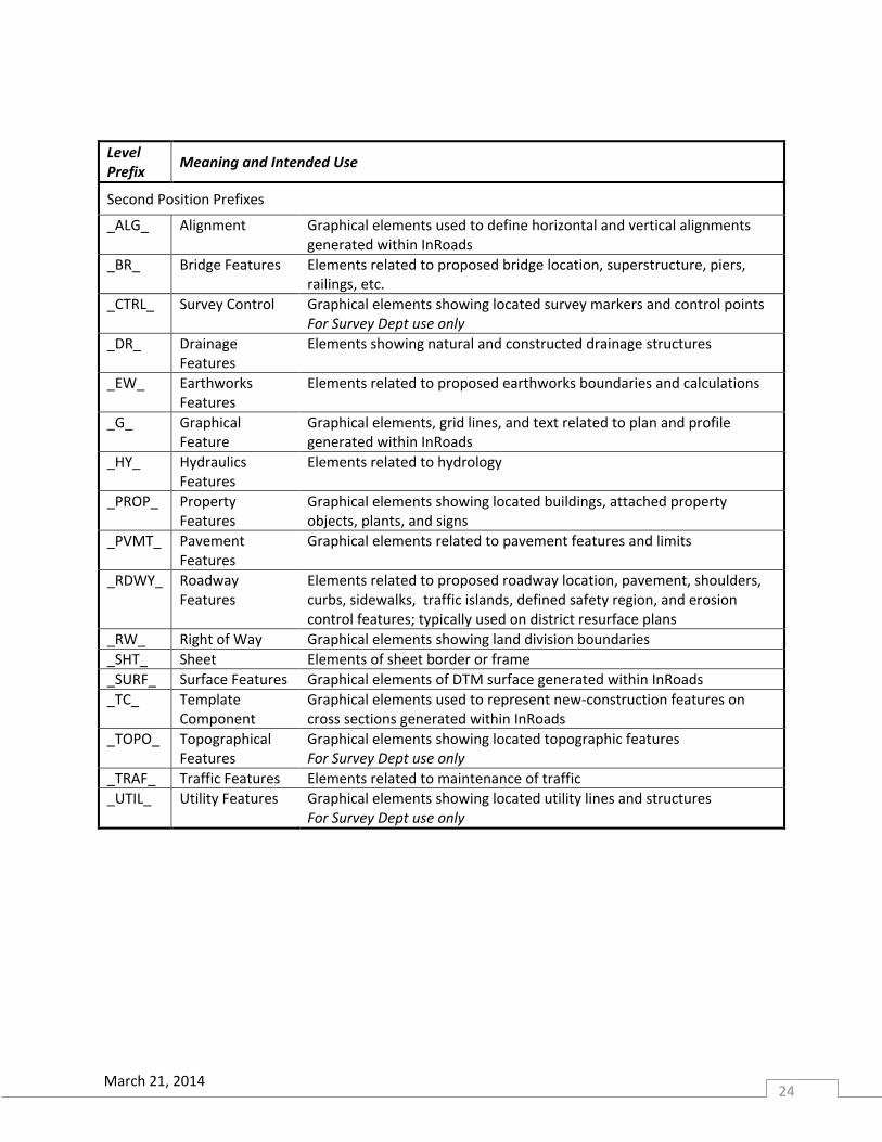
Level Prefix
Meaning and Intended Use
Second Position Prefixes
_ALG_ Alignment Graphical elements used to define horizontal and vertical alignments generated within InRoads
_BR_ Bridge Features Elements related to proposed bridge location, superstructure, piers, railings, etc.
_CTRL_ Survey Control Graphical elements showing located survey markers and control points For Survey Dept use only
_DR_ Drainage Features
Elements showing natural and constructed drainage structures
_EW_ Earthworks Features
Elements related to proposed earthworks boundaries and calculations
_G_ Graphical Feature
Graphical elements, grid lines, and text related to plan and profile generated within InRoads
_HY_ Hydraulics Features
Elements related to hydrology
_PROP_ Property Features
Graphical elements showing located buildings, attached property objects, plants, and signs
_PVMT_ Pavement Features
Graphical elements related to pavement features and limits
_RDWY_ Roadway Features
Elements related to proposed roadway location, pavement, shoulders, curbs, sidewalks, traffic islands, defined safety region, and erosion control features; typically used on district resurface plans
_RW_ Right of Way Graphical elements showing land division boundaries
_SHT_ Sheet Elements of sheet border or frame
_SURF_ Surface Features Graphical elements of DTM surface generated within InRoads
_TC_ Template Component
Graphical elements used to represent new-construction features on cross sections generated within InRoads
_TOPO_ Topographical Features
Graphical elements showing located topographic features For Survey Dept use only
_TRAF_ Traffic Features Elements related to maintenance of traffic
_UTIL_ Utility Features Graphical elements showing located utility lines and structures For Survey Dept use only
March 21, 2014 25
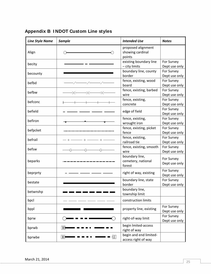
Appendix B INDOT Custom Line styles
Line Style Name Sample Intended Use Notes
Align
proposed alignment showing cardinal points
becity existing boundary line – city limits
For Survey Dept use only
becounty boundary line, county border
For Survey Dept use only
befbd fence, existing, wood board
For Survey Dept use only
befbw fence, existing, barbed wire
For Survey Dept use only
befconc fence, existing, concrete
For Survey Dept use only
befield edge of field For Survey Dept use only
befiron fence, existing, wrought iron
For Survey Dept use only
befpcket fence, existing, picket fence
For Survey Dept use only
befrail fence, existing, railroad tie
For Survey Dept use only
befsw fence, existing, smooth wire
For Survey Dept use only
beparks
boundary line, cemetery, national forest
For Survey Dept use only
beprprty right of way, existing For Survey Dept use only
bestate boundary line, state border
For Survey Dept use only
betwnshp boundary line, township limit
bpcl construction limits
bppl property line, existing For Survey Dept use only
bprw right‐of‐way limit For Survey Dept use only
bprwb begin lmited‐access right of way
bprwbe begin and end limited‐access right of way
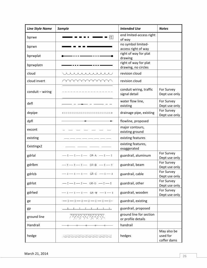
March 21, 2014 26
Line Style Name Sample Intended Use Notes
bprwe
end lmited‐access right of way
bprwn no symbol limited‐access right of way
bprwplat right of way for plat drawing
bprwplatn right of way for plat drawing, no circles
cloud revision cloud
cloud invert revision cloud
conduit – wiring conduit wiring, traffic signal detail
For Survey Dept use only
defl water flow line, existing
For Survey Dept use only
depipe drainage pipe, existing For Survey Dept use only
dpfl flowline, proposed
excont major contours, existing ground
existing existing features
Existingx2 existing features, exaggerated
gdrlal guardrail, aluminum For Survey Dept use only
gdrlbm guardrail, beam For Survey Dept use only
gdrlcb guardrail, cable For Survey Dept use only
gdrlot guardrail, other For Survey Dept use only
gdrlwd guardrail, wooden For Survey Dept use only
ge guardrail, existing
gp guardrail, proposed
ground line
ground line for section or profile details
Handrail handrail
hedge hedges May also be used for coffer dams
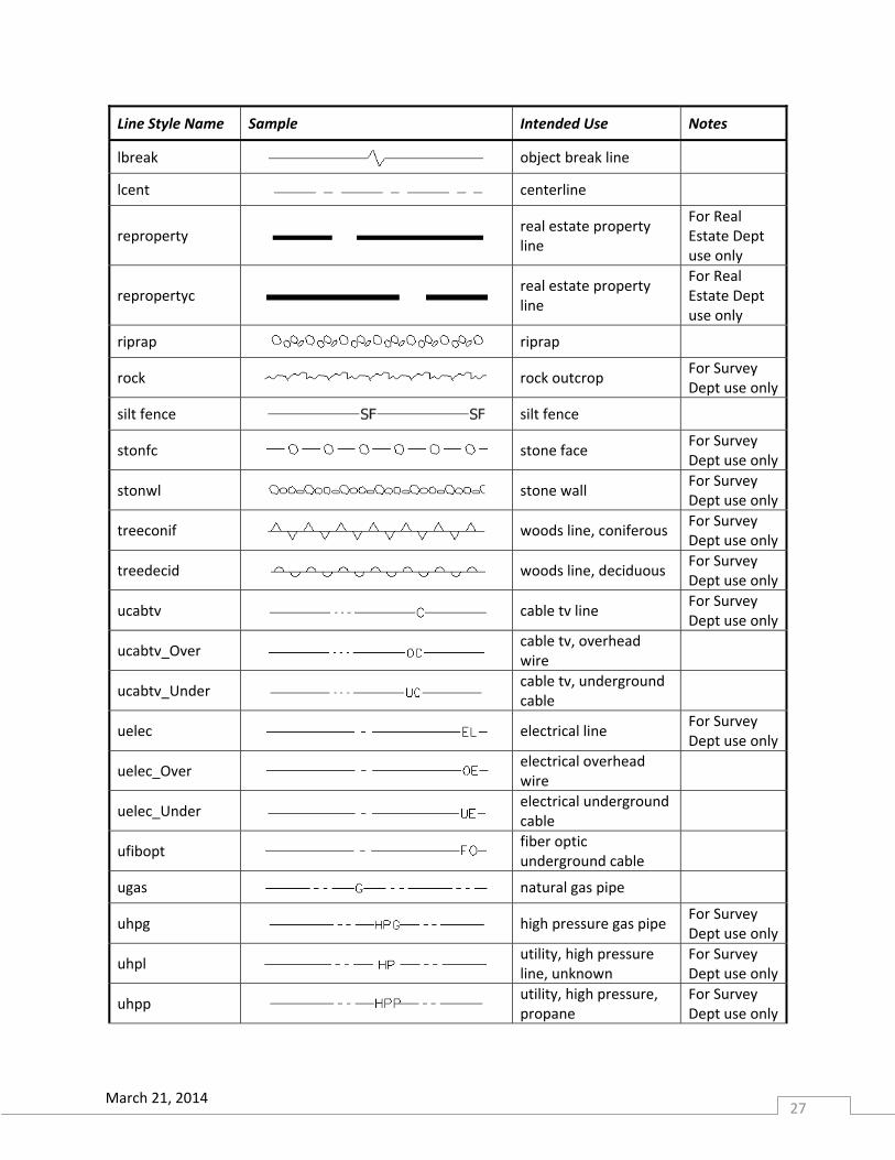
March 21, 2014 27
Line Style Name Sample Intended Use Notes
lbreak object break line
lcent centerline
reproperty real estate property line
For Real Estate Dept use only
repropertyc real estate property line
For Real Estate Dept use only
riprap riprap
rock rock outcrop For Survey Dept use only
silt fence silt fence
stonfc stone face For Survey Dept use only
stonwl stone wall For Survey Dept use only
treeconif woods line, coniferous For Survey Dept use only
treedecid woods line, deciduous For Survey Dept use only
ucabtv cable tv line For Survey Dept use only
ucabtv_Over cable tv, overhead wire
ucabtv_Under cable tv, underground cable
uelec electrical line For Survey Dept use only
uelec_Over electrical overhead wire
uelec_Under electrical underground cable
ufibopt fiber optic underground cable
ugas natural gas pipe
uhpg high pressure gas pipe For Survey Dept use only
uhpl utility, high pressure line, unknown
For Survey Dept use only
uhpp utility, high pressure, propane
For Survey Dept use only
March 21, 2014 28
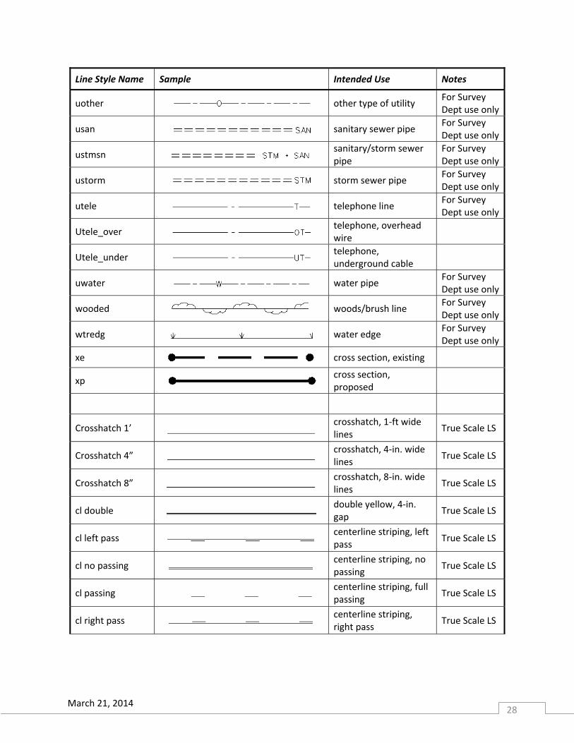
Line Style Name Sample Intended Use Notes
uother other type of utility For Survey Dept use only
usan sanitary sewer pipe For Survey Dept use only
ustmsn sanitary/storm sewer pipe
For Survey Dept use only
ustorm storm sewer pipe For Survey Dept use only
utele telephone line For Survey Dept use only
Utele_over telephone, overhead wire
Utele_under telephone, underground cable
uwater water pipe For Survey Dept use only
wooded
woods/brush line For Survey Dept use only
wtredg water edge For Survey Dept use only
xe cross section, existing
xp cross section, proposed
Crosshatch 1’ crosshatch, 1‐ft wide lines
True Scale LS
Crosshatch 4” crosshatch, 4‐in. wide lines
True Scale LS
Crosshatch 8” crosshatch, 8‐in. wide lines
True Scale LS
cl double double yellow, 4‐in. gap
True Scale LS
cl left pass centerline striping, left pass
True Scale LS
cl no passing centerline striping, no passing
True Scale LS
cl passing centerline striping, full passing
True Scale LS
cl right pass centerline striping, right pass
True Scale LS
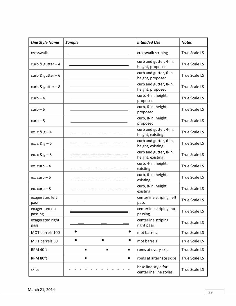
March 21, 2014 29
Line Style Name Sample Intended Use Notes
crosswalk crosswalk striping True Scale LS
curb & gutter – 4 curb and gutter, 4‐in. height, proposed
True Scale LS
curb & gutter – 6 curb and gutter, 6‐in. height, proposed
True Scale LS
curb & gutter – 8 curb and gutter, 8‐in. height, proposed
True Scale LS
curb – 4 curb, 4‐in. height, proposed
True Scale LS
curb – 6 curb, 6‐in. height, proposed
True Scale LS
curb – 8 curb, 8‐in. height, proposed
True Scale LS
ex. c & g – 4 curb and gutter, 4‐in. height, existing
True Scale LS
ex. c & g – 6 curb and gutter, 6‐in. height, existing
True Scale LS
ex. c & g – 8 curb and gutter, 8‐in. height, existing
True Scale LS
ex. curb – 4 curb, 4‐in. height, existing
True Scale LS
ex. curb – 6 curb, 6‐in. height, existing
True Scale LS
ex. curb – 8 curb, 8‐in. height, existing
True Scale LS
exagerated left pass
centerline striping, left pass
True Scale LS
exagerated no passing
centerline striping, no passing
True Scale LS
exagerated right pass
centerline striping, right pass
True Scale LS
MOT barrels 100 mot barrels True Scale LS
MOT barrels 50 mot barrels True Scale LS
RPM 40ft rpms at every skip True Scale LS
RPM 80ft rpms at alternate skips True Scale LS
skips base line style for centerline line styles
True Scale LS
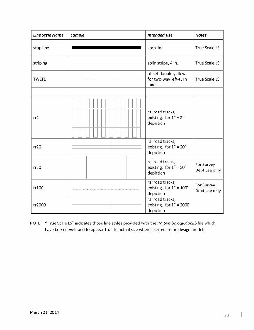
March 21, 2014 30
Line Style Name Sample Intended Use Notes
stop line stop line True Scale LS
striping solid stripe, 4 in. True Scale LS
TWLTL offset double yellow for two‐way left‐turn lane
True Scale LS
rr2 railroad tracks, existing, for 1” = 2’ depiction
rr20
railroad tracks, existing, for 1” = 20’ depiction
rr50 railroad tracks, existing, for 1” = 50’ depiction
For Survey Dept use only
rr100
railroad tracks, existing, for 1” = 100’ depiction
For Survey Dept use only
rr2000
railroad tracks, existing, for 1” = 2000’ depiction
NOTE: “ True Scale LS” indicates those line styles provided with the IN_Symbology.dgnlib file which
have been developed to appear true to actual size when inserted in the design model.
March 21, 2014 31
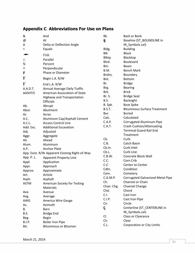
Appendix C Abbreviations For Use on Plans
& And @ At Δ Delta or Deflection Angle = Equals Fish
| | Parallel % Percent
┴ Perpendicular 0/ Phase or Diameter
B Begin L.A. R/W
E End L.A. R/W A.A.D.T. Annual Average Daily Traffic AASHTO American Association of State
Highway and Transportation Officials
Ab. Abrupt Abut. Abutment Ac Acres A.C. Aluminum Cap/Asphalt Cement A.C.L. Access Control Line Add. Exc. Additional Excavation Adj. Adjusted Aggr. Aggregate Ah. Ahead Alum. Aluminum A.P. Anchor Plate App. Exist. R/W Apparent Existing Right-of-Way App. P. L. Apparent Property Line Appl. Application Appr. Approach Approx. Approximate Art. Article Asph. Asphalt ASTM American Society for Testing
Materials Ave. Avenue Avg. Average AWG America Wire Gauge Az. Azimuth B. Barn B.E. Bridge End Beg. Begin B.I.P. Boiler Iron Pipe Bit. Bituminous or Bitumen
Bk. Back or Bank Baseline (ST_BOUNDLINE in
IN_Symbols.cel) Bldg. Building Blk Block Blktp. Blacktop Blvd. Boulevard Bm. Beam B.M. Bench Mark Bndry. Boundary Bot. Bottom Br. Bridge Brg. Bearing Brk. Brick Br. S. Bridge Seat B.S. Backsight B. Spk. Boat Spike B.S.T. Bituminous Surface Treatment Bur. Buried Calc. Calculated C.A.P. Corrugated Aluminum Pipe C.A.T. Crash Cushion/Attenuating
Terminal Guard Rail End Treatment
Cb. Curb C.B. Catch Basin Cb.In. Curb Inlet Cb.L. Curb Line C.B.W. Concrete Block Wall C.C. Corn Crib C-C Center to Center Cdtn. Condition Cem. Cemetery C.G.M.P. Corrugated Galvanized Metal Pipe Ch. Channel or Chain Chan. Chg. Channel Change Chd. Chord C.I. Cast Iron C.I.P. Cast Iron Pipe Cir. Circle Centerline (ST_CENTERLINE in
IN_Symbols.cel) Cl. Class or Clearance Clr. Clear C.L. Corporation or City Limits
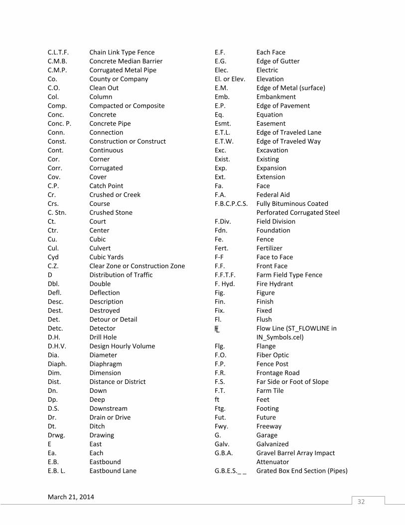
March 21, 2014 32
C.L.T.F. Chain Link Type Fence C.M.B. Concrete Median Barrier C.M.P. Corrugated Metal Pipe Co. County or Company C.O. Clean Out Col. Column Comp. Compacted or Composite Conc. Concrete Conc. P. Concrete Pipe Conn. Connection Const. Construction or Construct Cont. Continuous Cor. Corner Corr. Corrugated Cov. Cover C.P. Catch Point Cr. Crushed or Creek Crs. Course C. Stn. Crushed Stone Ct. Court Ctr. Center Cu. Cubic Cul. Culvert Cyd Cubic Yards C.Z. Clear Zone or Construction Zone D Distribution of Traffic Dbl. Double Defl. Deflection Desc. Description Dest. Destroyed Det. Detour or Detail Detc. Detector D.H. Drill Hole D.H.V. Design Hourly Volume Dia. Diameter Diaph. Diaphragm Dim. Dimension Dist. Distance or District Dn. Down Dp. Deep D.S. Downstream Dr. Drain or Drive Dt. Ditch Drwg. Drawing E East Ea. Each E.B. Eastbound E.B. L. Eastbound Lane
E.F. Each Face E.G. Edge of Gutter Elec. Electric El. or Elev. Elevation E.M. Edge of Metal (surface) Emb. Embankment E.P. Edge of Pavement Eq. Equation Esmt. Easement E.T.L. Edge of Traveled Lane E.T.W. Edge of Traveled Way Exc. Excavation Exist. Existing Exp. Expansion Ext. Extension Fa. Face F.A. Federal Aid F.B.C.P.C.S. Fully Bituminous Coated
Perforated Corrugated Steel F.Div. Field Division Fdn. Foundation Fe. Fence Fert. Fertilizer F-F Face to Face F.F. Front Face F.F.T.F. Farm Field Type Fence F. Hyd. Fire Hydrant Fig. Figure Fin. Finish Fix. Fixed Fl. Flush Flow Line (ST_FLOWLINE in
IN_Symbols.cel) Flg. Flange F.O. Fiber Optic F.P. Fence Post F.R. Frontage Road F.S. Far Side or Foot of Slope F.T. Farm Tile ft Feet Ftg. Footing Fut. Future Fwy. Freeway G. Garage Galv. Galvanized G.B.A. Gravel Barrel Array Impact
Attenuator G.B.E.S._ _ Grated Box End Section (Pipes)
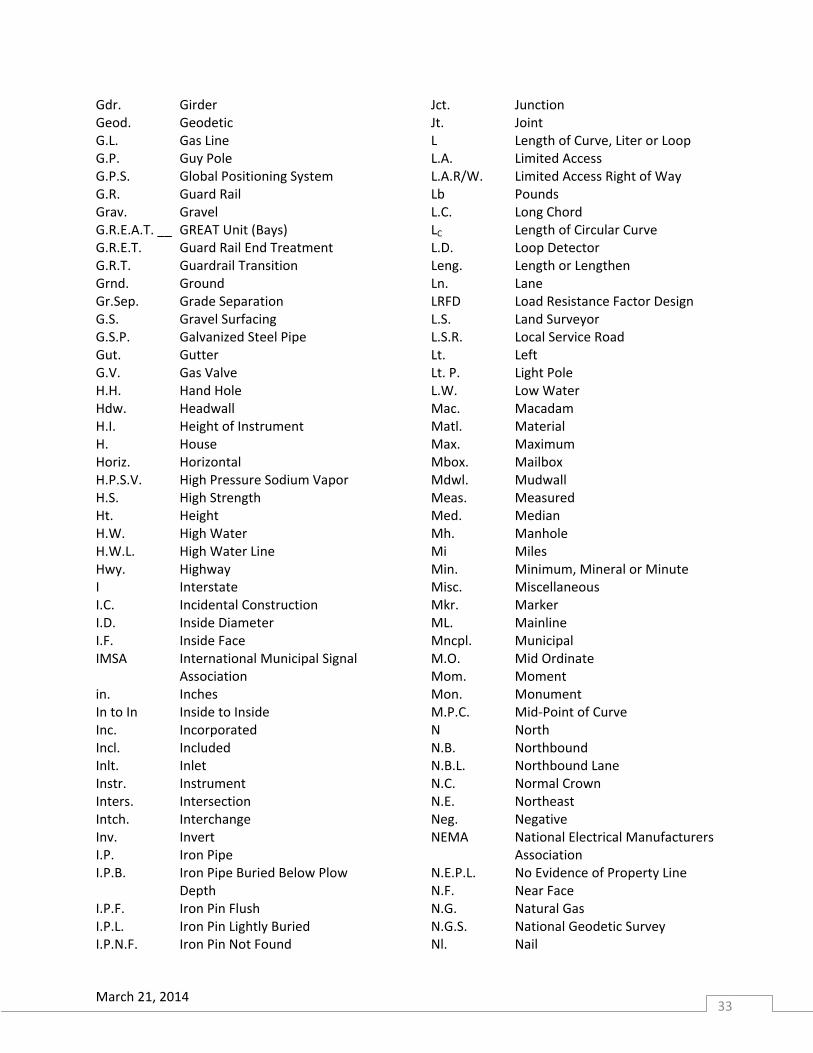
March 21, 2014 33
Gdr. Girder Geod. Geodetic G.L. Gas Line G.P. Guy Pole G.P.S. Global Positioning System G.R. Guard Rail Grav. Gravel G.R.E.A.T. __ GREAT Unit (Bays) G.R.E.T. Guard Rail End Treatment G.R.T. Guardrail Transition Grnd. Ground Gr.Sep. Grade Separation G.S. Gravel Surfacing G.S.P. Galvanized Steel Pipe Gut. Gutter G.V. Gas Valve H.H. Hand Hole Hdw. Headwall H.I. Height of Instrument H. House Horiz. Horizontal H.P.S.V. High Pressure Sodium Vapor H.S. High Strength Ht. Height H.W. High Water H.W.L. High Water Line Hwy. Highway I Interstate I.C. Incidental Construction I.D. Inside Diameter I.F. Inside Face IMSA International Municipal Signal
Association in. Inches In to In Inside to Inside Inc. Incorporated Incl. Included Inlt. Inlet Instr. Instrument Inters. Intersection Intch. Interchange Inv. Invert I.P. Iron Pipe I.P.B. Iron Pipe Buried Below Plow
Depth I.P.F. Iron Pin Flush I.P.L. Iron Pin Lightly Buried I.P.N.F. Iron Pin Not Found
Jct. Junction Jt. Joint L Length of Curve, Liter or Loop L.A. Limited Access L.A.R/W. Limited Access Right of Way Lb Pounds L.C. Long Chord LC Length of Circular Curve L.D. Loop Detector Leng. Length or Lengthen Ln. Lane LRFD Load Resistance Factor Design L.S. Land Surveyor L.S.R. Local Service Road Lt. Left Lt. P. Light Pole L.W. Low Water Mac. Macadam Matl. Material Max. Maximum Mbox. Mailbox Mdwl. Mudwall Meas. Measured Med. Median Mh. Manhole Mi Miles Min. Minimum, Mineral or Minute Misc. Miscellaneous Mkr. Marker ML. Mainline Mncpl. Municipal M.O. Mid Ordinate Mom. Moment Mon. Monument M.P.C. Mid-Point of Curve N North N.B. Northbound N.B.L. Northbound Lane N.C. Normal Crown N.E. Northeast Neg. Negative NEMA National Electrical Manufacturers
Association N.E.P.L. No Evidence of Property Line N.F. Near Face N.G. Natural Gas N.G.S. National Geodetic Survey Nl. Nail
March 21, 2014 34
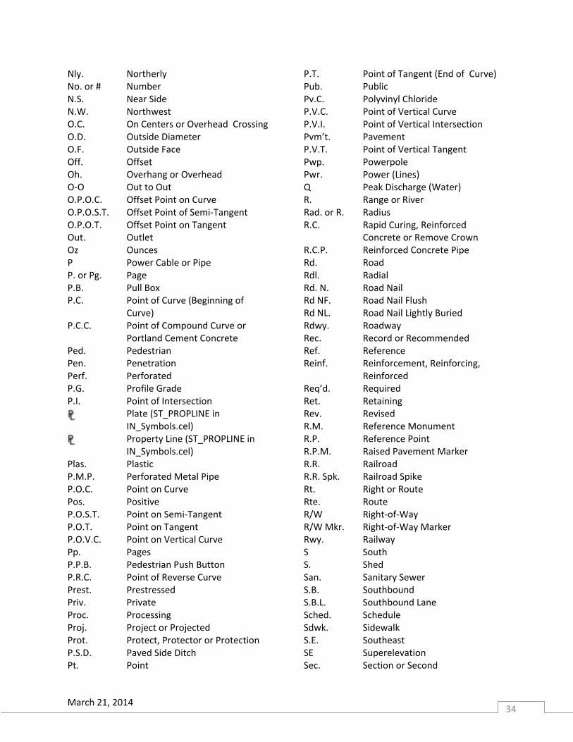
Nly. Northerly No. or # Number N.S. Near Side N.W. Northwest O.C. On Centers or Overhead Crossing O.D. Outside Diameter O.F. Outside Face Off. Offset Oh. Overhang or Overhead O-O Out to Out O.P.O.C. Offset Point on Curve O.P.O.S.T. Offset Point of Semi-Tangent O.P.O.T. Offset Point on Tangent Out. Outlet Oz Ounces P Power Cable or Pipe P. or Pg. Page P.B. Pull Box P.C. Point of Curve (Beginning of
Curve) P.C.C. Point of Compound Curve or
Portland Cement Concrete Ped. Pedestrian Pen. Penetration Perf. Perforated P.G. Profile Grade P.I. Point of Intersection Plate (ST_PROPLINE in
IN_Symbols.cel) Property Line (ST_PROPLINE in
IN_Symbols.cel) Plas. Plastic P.M.P. Perforated Metal Pipe P.O.C. Point on Curve Pos. Positive P.O.S.T. Point on Semi-Tangent P.O.T. Point on Tangent P.O.V.C. Point on Vertical Curve Pp. Pages P.P.B. Pedestrian Push Button P.R.C. Point of Reverse Curve Prest. Prestressed Priv. Private Proc. Processing Proj. Project or Projected Prot. Protect, Protector or Protection P.S.D. Paved Side Ditch Pt. Point
P.T. Point of Tangent (End of Curve) Pub. Public Pv.C. Polyvinyl Chloride P.V.C. Point of Vertical Curve P.V.I. Point of Vertical Intersection Pvm’t. Pavement P.V.T. Point of Vertical Tangent Pwp. Powerpole Pwr. Power (Lines) Q Peak Discharge (Water) R. Range or River Rad. or R. Radius R.C. Rapid Curing, Reinforced
Concrete or Remove Crown R.C.P. Reinforced Concrete Pipe Rd. Road Rdl. Radial Rd. N. Road Nail Rd NF. Road Nail Flush Rd NL. Road Nail Lightly Buried Rdwy. Roadway Rec. Record or Recommended Ref. Reference Reinf. Reinforcement, Reinforcing,
Reinforced Req’d. Required Ret. Retaining Rev. Revised R.M. Reference Monument R.P. Reference Point R.P.M. Raised Pavement Marker R.R. Railroad R.R. Spk. Railroad Spike Rt. Right or Route Rte. Route R/W Right-of-Way R/W Mkr. Right-of-Way Marker Rwy. Railway S South S. Shed San. Sanitary Sewer S.B. Southbound S.B.L. Southbound Lane Sched. Schedule Sdwk. Sidewalk S.E. Southeast SE Superelevation Sec. Section or Second
March 21, 2014 35
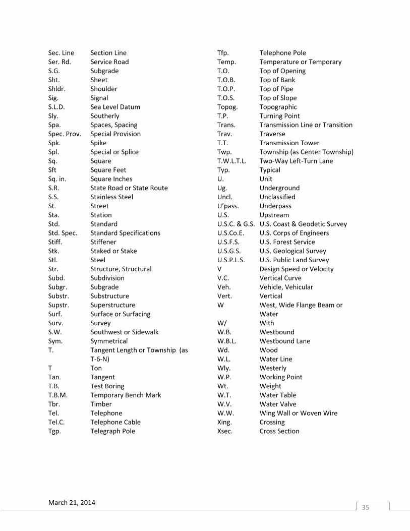
Sec. Line Section Line Ser. Rd. Service Road S.G. Subgrade Sht. Sheet Shldr. Shoulder Sig. Signal S.L.D. Sea Level Datum Sly. Southerly Spa. Spaces, Spacing Spec. Prov. Special Provision Spk. Spike Spl. Special or Splice Sq. Square Sft Square Feet Sq. in. Square Inches S.R. State Road or State Route S.S. Stainless Steel St. Street Sta. Station Std. Standard Std. Spec. Standard Specifications Stiff. Stiffener Stk. Staked or Stake Stl. Steel Str. Structure, Structural Subd. Subdivision Subgr. Subgrade Substr. Substructure Supstr. Superstructure Surf. Surface or Surfacing Surv. Survey S.W. Southwest or Sidewalk Sym. Symmetrical T. Tangent Length or Township (as
T-6-N) T Ton Tan. Tangent T.B. Test Boring T.B.M. Temporary Bench Mark Tbr. Timber Tel. Telephone Tel.C. Telephone Cable Tgp. Telegraph Pole
Tfp. Telephone Pole Temp. Temperature or Temporary T.O. Top of Opening T.O.B. Top of Bank T.O.P. Top of Pipe T.O.S. Top of Slope Topog. Topographic T.P. Turning Point Trans. Transmission Line or Transition Trav. Traverse T.T. Transmission Tower Twp. Township (as Center Township) T.W.L.T.L. Two-Way Left-Turn Lane Typ. Typical U. Unit Ug. Underground Uncl. Unclassified U’pass. Underpass U.S. Upstream U.S.C. & G.S. U.S. Coast & Geodetic Survey U.S.Co.E. U.S. Corps of Engineers U.S.F.S. U.S. Forest Service U.S.G.S. U.S. Geological Survey U.S.P.L.S. U.S. Public Land Survey V Design Speed or Velocity V.C. Vertical Curve Veh. Vehicle, Vehicular Vert. Vertical W West, Wide Flange Beam or
Water W/ With W.B. Westbound W.B.L. Westbound Lane Wd. Wood W.L. Water Line Wly. Westerly W.P. Working Point Wt. Weight W.T. Water Table W.V. Water Valve W.W. Wing Wall or Woven Wire Xing. Crossing Xsec. Cross Section

March 21, 2014 36
(Blank Page)
March 21, 2014 37
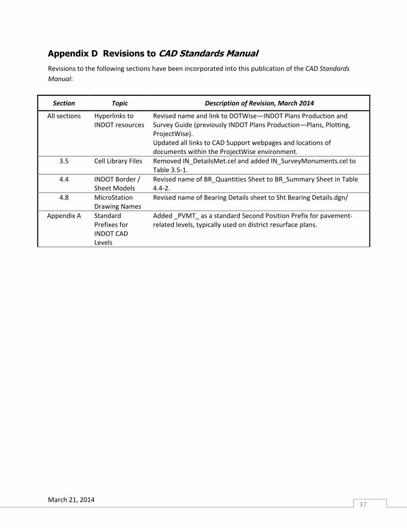
Appendix D Revisions to CAD Standards Manual
Revisions to the following sections have been incorporated into this publication of the CAD Standards
Manual:
Section Topic Description of Revision, March 2014
All sections Hyperlinks to INDOT resources
Revised name and link to DOTWise—INDOT Plans Production and Survey Guide (previously INDOT Plans Production—Plans, Plotting, ProjectWise). Updated all links to CAD Support webpages and locations of documents within the ProjectWise environment.
3.5 Cell Library Files Removed IN_DetailsMet.cel and added IN_SurveyMonuments.cel to Table 3.5-1.
4.4 INDOT Border / Sheet Models
Revised name of BR_Quantities Sheet to BR_Summary Sheet in Table 4.4-2.
4.8 MicroStation Drawing Names
Revised name of Bearing Details sheet to Sht Bearing Details.dgn/
Appendix A Standard Prefixes for INDOT CAD Levels
Added _PVMT_ as a standard Second Position Prefix for pavement-related levels, typically used on district resurface plans.
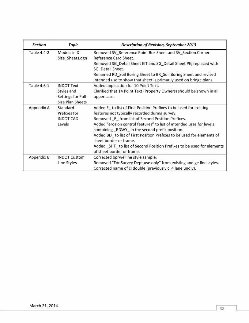
March 21, 2014 38
Section Topic Description of Revision, September 2013
Table 4.4-2 Models in D Size_Sheets.dgn
Removed SV_Reference Point Box Sheet and SV_Section Corner Reference Card Sheet. Removed SG_Detail Sheet EIT and SG_Detail Sheet PE; replaced with SG_Detail Sheet. Renamed RD_Soil Boring Sheet to BR_Soil Boring Sheet and revised intended use to show that sheet is primarily used on bridge plans.
Table 4.6-1 INDOT Text Styles and Settings for Full-Size Plan Sheets
Added application for 10 Point Text. Clarified that 14 Point Text (Property Owners) should be shown in all upper case.
Appendix A Standard Prefixes for INDOT CAD Levels
Added E_ to list of First Position Prefixes to be used for existing features not typically recorded during survey. Removed _E_ from list of Second Position Prefixes. Added “erosion control features” to list of intended uses for levels containing _RDWY_ in the second prefix position. Added BD_ to list of First Position Prefixes to be used for elements of sheet border or frame. Added _SHT_ to list of Second Position Prefixes to be used for elements of sheet border or frame.
Appendix B INDOT Custom Line Styles
Corrected bprwe line style sample. Removed “For Survey Dept use only” from existing and ge line styles. Corrected name of cl double (previously cl 4 lane undiv).
March 21, 2014 39
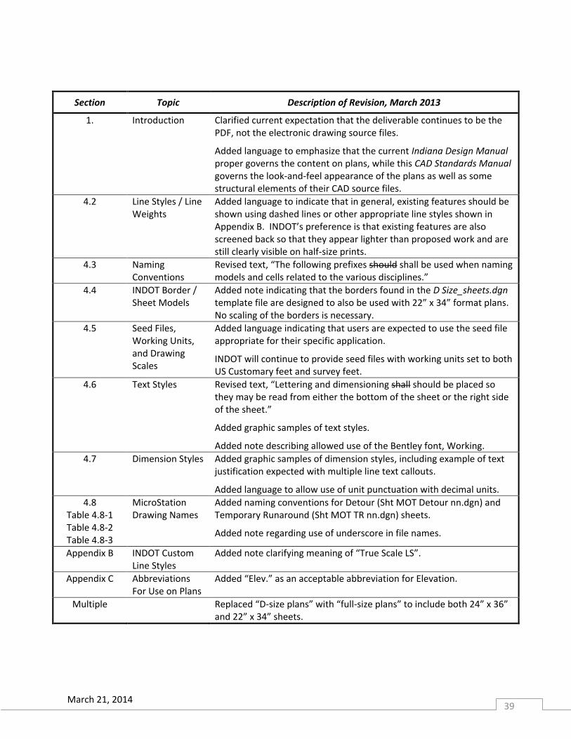
Section Topic Description of Revision, March 2013
1. Introduction Clarified current expectation that the deliverable continues to be the PDF, not the electronic drawing source files.
Added language to emphasize that the current Indiana Design Manual proper governs the content on plans, while this CAD Standards Manual governs the look-and-feel appearance of the plans as well as some structural elements of their CAD source files.
4.2 Line Styles / Line Weights
Added language to indicate that in general, existing features should be shown using dashed lines or other appropriate line styles shown in Appendix B. INDOT’s preference is that existing features are also screened back so that they appear lighter than proposed work and are still clearly visible on half-size prints.
4.3 Naming Conventions
Revised text, “The following prefixes should shall be used when naming models and cells related to the various disciplines.”
4.4 INDOT Border / Sheet Models
Added note indicating that the borders found in the D Size_sheets.dgn template file are designed to also be used with 22” x 34” format plans. No scaling of the borders is necessary.
4.5 Seed Files, Working Units, and Drawing Scales
Added language indicating that users are expected to use the seed file appropriate for their specific application.
INDOT will continue to provide seed files with working units set to both US Customary feet and survey feet.
4.6 Text Styles Revised text, “Lettering and dimensioning shall should be placed so they may be read from either the bottom of the sheet or the right side of the sheet.”
Added graphic samples of text styles.
Added note describing allowed use of the Bentley font, Working.
4.7 Dimension Styles Added graphic samples of dimension styles, including example of text justification expected with multiple line text callouts.
Added language to allow use of unit punctuation with decimal units.
4.8 Table 4.8-1 Table 4.8-2 Table 4.8-3
MicroStation Drawing Names
Added naming conventions for Detour (Sht MOT Detour nn.dgn) and Temporary Runaround (Sht MOT TR nn.dgn) sheets.
Added note regarding use of underscore in file names.
Appendix B INDOT Custom Line Styles
Added note clarifying meaning of “True Scale LS”.
Appendix C Abbreviations For Use on Plans
Added “Elev.” as an acceptable abbreviation for Elevation.
Multiple Replaced “D-size plans” with “full-size plans” to include both 24” x 36” and 22” x 34” sheets.