Embed Size (px)
Citation preview
Indoor Radio MapperUser GuideVersion 4.7
Indoor Radio Mapper User Guide► Notices
2
Important Information NoticesTopics:
• Legal Notices• Document Information
This section contains document notices.
Indoor Radio Mapper User Guide► Notices
3
Legal Notices© 2018 HERE Global B.V. and its Affiliate(s). All rights reserved.
This material, including documentation and any related computer programs, is protected by copyrightcontrolled by HERE. All rights are reserved. Copying, including reproducing, storing, adapting or translating,any or all of this material requires the prior written consent of HERE. This material also contains confidentialinformation, which may not be disclosed to others without the prior written consent of HERE.
Trademark Acknowledgements
HERE is trademark or registered trademark of HERE Global B.V.
Other product and company names mentioned herein may be trademarks or trade names of their respectiveowners.
Disclaimer
This content is provided "as-is" and without warranties of any kind, either express or implied, including, butnot limited to, the implied warranties of merchantability, fitness for a particular purpose, satisfactory qualityand non-infringement. HERE does not warrant that the content is error free and HERE does not warrant ormake any representations regarding the quality, correctness, accuracy, or reliability of the content. Youshould therefore verify any information contained in the content before acting on it.
To the furthest extent permitted by law, under no circumstances, including without limitation the negligenceof HERE, shall HERE be liable for any damages, including, without limitation, direct, special, indirect, punitive,consequential, exemplary and/ or incidental damages that result from the use or application of this content,even if HERE or an authorized representative has been advised of the possibility of such damages.
Indoor Radio Mapper User Guide► Notices
4
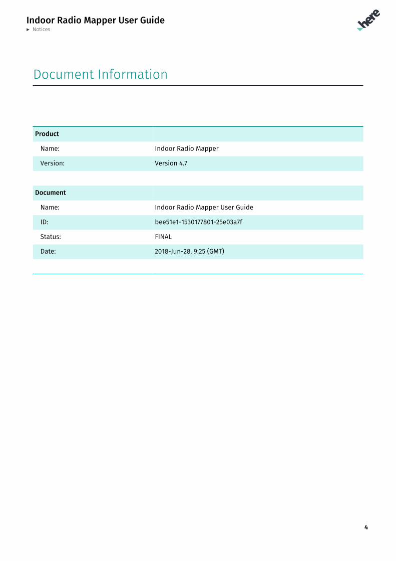
Document Information
Product
Name: Indoor Radio Mapper
Version: Version 4.7
Document
Name: Indoor Radio Mapper User Guide
ID: bee51e1-1530177801-25e03a7f
Status: FINAL
Date: 2018-Jun-28, 9:25 (GMT)
Indoor Radio Mapper User Guide► Contents
5
Contents
Chapter 1: Introduction.................................................................................................................................................................. 7What is HERE Indoor Radio Mapper?.......................................................................................................................................................8
Chapter 2: Quick start......................................................................................................................................................................9Prerequisites........................................................................................................................................................................................................10
Quick Start Workflow.......................................................................................................................................................................................11
Logging In..............................................................................................................................................................................................................12
Demo mode..........................................................................................................................................................................................................12
Chapter 3: Navigating in the Indoor Radio Mapper..............................................................................13Basic Navigation................................................................................................................................................................................................ 14
Selecting and Managing Venues...............................................................................................................................................................16
Selecting and Managing Activities........................................................................................................................................................... 17
Chapter 4: Custom Image-Based Venues............................................................................................................19Prerequisites for Using Custom Image-based Indoor Maps......................................................................................................20
Importing Custom Indoor Maps................................................................................................................................................................20
Manual Calibration........................................................................................................................................................................................... 21
Chapter 5: Collecting Radio Data..................................................................................................................................23Collect Data View..............................................................................................................................................................................................24
How to Collect Radio Data.......................................................................................................................................................................... 25
Collecting Radio Data Indoors...................................................................................................................................................................26
Collecting Radio Data in Connectors.....................................................................................................................................................28
Collecting Radio Data Outdoors...............................................................................................................................................................28
Collecting Radio Data With Custom Indoor Maps...........................................................................................................................30
Showing the Data Collected by Others.................................................................................................................................................31
Automated Radio Data Quality Analysis.............................................................................................................................................. 32
Chapter 6: Managing Radio Data in Floor Detail view...................................................................... 36Floor Radio Data Management..................................................................................................................................................................37
Indoor Radio Mapper User Guide► Contents
6
Storing Collected Radio Data.....................................................................................................................................................................38
Chapter 7: Testing Positioning Performance.................................................................................................39Testing Positioning Real-Time...................................................................................................................................................................40
Chapter 8: Publishing Radio Data................................................................................................................................42Publishing Flow..................................................................................................................................................................................................43
Chapter 9: Advanced features.......................................................................................................................................... 44Collecting Test Tracks.................................................................................................................................................................................... 45
Running a Test Track......................................................................................................................................................................................46
SLAM Mode for Radio Data Collection (beta)....................................................................................................................................47
Chapter 10: FAQ.....................................................................................................................................................................................50Why do I have to walk in straight lines at constant speed?.....................................................................................................51
Why do I need to align my own custom indoor maps to Latitude and Longitude coordinates?.............................51
Are there any device settings that I should be aware of?......................................................................................................... 51
Indoor Radio Mapper User Guide► Introduction
7
Chapter 1IntroductionTopics:
• What is HERE Indoor Radio ...
This document provides information on how to use the HERE IndoorRadio Mapper to
• access HERE Private and Public Venue Maps
• import and align your own custom indoor maps
• collect radio data inside and outside of venues by using theindoor maps
• manage the collected radio data
• analyze the quality of data collection and radio infrastructure inthe venue
• publish the collected radio data for HERE Mobile SDK
• test indoor positioning performance at the venue after the radiodata collection
Indoor Radio Mapper User Guide► Introduction
8
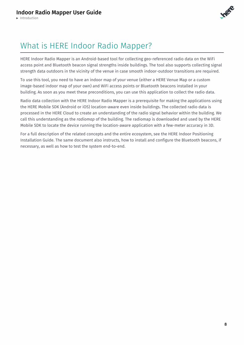
What is HERE Indoor Radio Mapper?HERE Indoor Radio Mapper is an Android-based tool for collecting geo-referenced radio data on the WiFiaccess point and Bluetooth beacon signal strengths inside buildings. The tool also supports collecting signalstrength data outdoors in the vicinity of the venue in case smooth indoor-outdoor transitions are required.
To use this tool, you need to have an indoor map of your venue (either a HERE Venue Map or a customimage-based indoor map of your own) and WiFi access points or Bluetooth beacons installed in yourbuilding. As soon as you meet these preconditions, you can use this application to collect the radio data.
Radio data collection with the HERE Indoor Radio Mapper is a prerequisite for making the applications usingthe HERE Mobile SDK (Android or iOS) location-aware even inside buildings. The collected radio data isprocessed in the HERE Cloud to create an understanding of the radio signal behavior within the building. Wecall this understanding as the radiomap of the building. The radiomap is downloaded and used by the HEREMobile SDK to locate the device running the location-aware application with a few-meter accuracy in 3D.
For a full description of the related concepts and the entire ecosystem, see the HERE Indoor PositioningInstallation Guide. The same document also instructs, how to install and configure the Bluetooth beacons, ifnecessary, as well as how to test the system end-to-end.
Indoor Radio Mapper User Guide► Quick start
9
Chapter 2Quick startTopics:
• Prerequisites• Quick Start Workflow• Logging In• Demo mode
This section gets you started with the HERE Indoor Radio Mapper injust a few minutes.
Indoor Radio Mapper User Guide► Quick start
10
PrerequisitesBefore you start working with the HERE Indoor Radio Mapper:
• HERE Indoor Radio Mapper needs to be installed to a device running Android version 5.0 (API level 21) upto 8.0.
• The device you intend to use must be suitable for the radio data collection. The main criteria for a high-quality measurement device is the support for dual-band WiFi, i.e. compatible with 2.4-GHz and 5-GHzWiFi bands, and a Bluetooth radio. Other quality criteria include high radio scanning rate (e.g. once pertwo seconds for WiFi), high sensitivity and accuracy of signal strength measurements as well as lowmeasurement noise.
For further information on the devices recommended for the radio data collection, see the HERE IndoorPositioning Installation Guide.
• You have access to an indoor map for a venue, where you want to test or deploy HERE IndoorPositioning.
In case you intend to use a HERE Private Venue Map, this needs to be deployed to your HERE Account byHERE.
If you intend to use your own custom image-based indoor map, please refer to Custom Image-BasedVenues on page 19 for supported image formats and other requirements.
If you intend to use any of HERE Public Venue Maps, they are available in HERE Indoor Radio Mapper incase you have HERE Indoor Positioning evaluation or indoor-public feature enabled in your HERE IndoorPositioning license.
• HERE Indoor Radio Mapper supports testing HERE Indoor Positioning right away after the radio datacollection. However, if you want to test HERE Indoor Positioning through the HERE Mobile SDK too, youneed to register for the 90-day free trial for the HERE Mobile SDK Premium for Android and/or iOS atHERE Developer Portal. For straighforward testing of the HERE Mobile SDK, please check out the examplesource codes for Android and iOS at GitHub.
Indoor Radio Mapper User Guide► Quick start
11
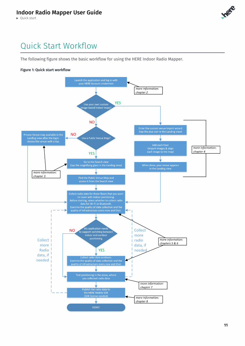
Quick Start WorkflowThe following figure shows the basic workflow for using the HERE Indoor Radio Mapper.
Figure 1: Quick start workflow
Indoor Radio Mapper User Guide► Quick start
12
The usage can be summarized in a few simple steps:
1. Install the application from Google Play and log in
2. Pick the indoor map to use
• HERE Private Venue Map will be accessible right from the Landing view
• HERE Public Venue Map will be accessible through the search
• Your own custom image-based venue can be imported through the wizard
3. Collect radio data indoors and, if necessary, also outdoors, every now and then checking both the datacollection and radio infrastructure quality views
4. Test positioning throughout the building
5. If there are any problems, go back to the step 3 and repeat radio data collection in problematic areas
6. Publish the positioning data for the HERE Mobile SDK
Note: This is only possible, if you have evaluation/commercial license for the HERE Mobile SDK.To sign-up for the evaluation, access the HERE Developer Portal.
Logging InTo log into the HERE Indoor Radio Mapper, you must have HERE Account credentials. You can create a HEREAccount, for example, here.
Before logging into the application, make sure your device is connected to a data network.
To log into the HERE Indoor Radio Mapper:
1. Launch the HERE Indoor Radio Mapper.
2. In the Login view, enter your HERE Account credentials.
Your credentials are checked and the Landing view appears.
Demo modeTo make the evaluation of the HERE Indoor Positioning as easy as possible, it is possible to use HERE IndoorRadio Mapper in the demo mode without the HERE Mobile SDK license.
The demo mode supports all the HERE Indoor Radio Mapper features with the only exception being theinability to publish the positioning data for consumption by the HERE Mobile SDK. To do this, you will needto have either an evaluation or commercial license to the HERE Mobile SDK. To sign-up for the evaluation,access the HERE Developer Portal.
Indoor Radio Mapper User Guide► Navigating in the Indoor Radio Mapper
13
Chapter 3Navigating in the Indoor RadioMapperTopics:
• Basic Navigation• Selecting and Managing Ven...• Selecting and Managing Act...
This section provides an overview on navigating in the HERE IndoorRadio Mapper and other basic functions.
Indoor Radio Mapper User Guide► Navigating in the Indoor Radio Mapper
14
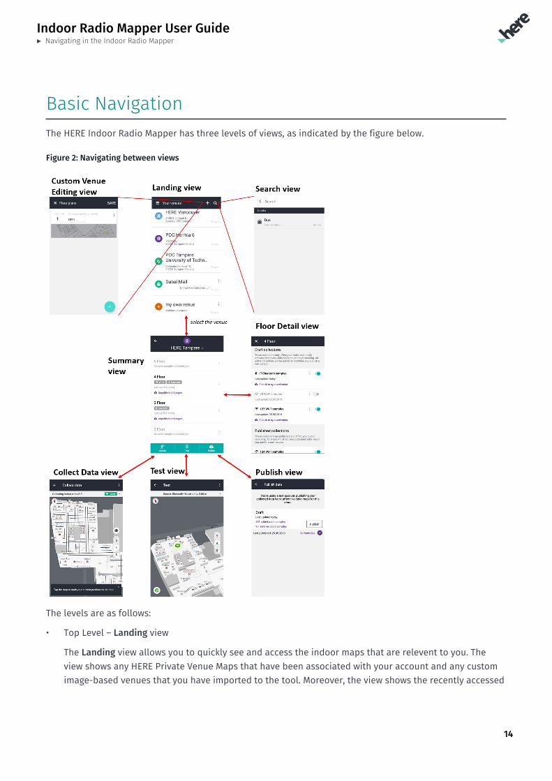
Basic NavigationThe HERE Indoor Radio Mapper has three levels of views, as indicated by the figure below.
Figure 2: Navigating between views
The levels are as follows:
• Top Level – Landing view
The Landing view allows you to quickly see and access the indoor maps that are relevent to you. Theview shows any HERE Private Venue Maps that have been associated with your account and any customimage-based venues that you have imported to the tool. Moreover, the view shows the recently accessed
Indoor Radio Mapper User Guide► Navigating in the Indoor Radio Mapper
15
HERE Public Venue Maps. Note that if there are no HERE Private Venue Maps associated with youraccount, the view is empty when you log in for the first time.
Note: The outlook of this view changes depending upon the features enabled in your HERE IndoorPositioning license. In case HERE Private Indoor Positioning feature is not enabled in your license,HERE Private Venue Maps will not be shown in the Landing view even if they were associated withyour HERE Account. Moreover, in case HERE Public Indoor Positioning feature is not enabled inyour license, HERE Public Venue Maps search shall be disabled.
Note: In the demo mode, you will have an access to HERE Public Venue Maps.
Additionally, the basic operations accessible from the Landing view include:
• To select a venue for the radio data collection, performance testing or radio data management,select the desired venue from the Landing view. For more information, see Selecting and ManagingVenues on page 16.
• To search for and access the HERE Public Venue Maps, access the Search view by tapping themagnifying glass.
• To add your own image-based custom venue to the HERE Indoor Radio Mapper, access the CustomVenue Editing view by tapping the plus-sign. See Custom Image-Based Venues on page 19 forfurther details.
• The three dots on the right side of HERE Public Venue Maps and custom indoor maps allows deletingan indoor map from the Landing view and accessing the Custom Venue Editing view for a particularcustom venue. HERE Private Venue Maps cannot be removed from the view.
• To log out, open the menu in the Landing view by sliding it from the left and select Log out
• To manage your settings, open the menu in the Landing view and select Settings. The importantitems in the Settings are:
▫ Units - switch between metric, Imperial UK and Imperial US units
▫ Offline test track - Enables or disables the test track functionality. See Advanced features onpage 44 for further details.
▫ Clear recent venues - clears the HERE Public Venue Maps and custom venues from the Landingview
• Second Level – Summary view
The Summary view provides the access to
• Collect radio data for each floor
• Manage radio data for each floor
• Test indoor positioning
• Publish positioning data for the HERE Mobile SDK
For more information, see Selecting and Managing Activities on page 17.
• Third Level – Collect, Test, Publish and Floor Detail views
For more information, see Collecting Radio Data on page 23, Testing Positioning Performance on page39, Publishing Radio Data on page 42 and Managing Radio Data in Floor Detail view on page 36.
Indoor Radio Mapper User Guide► Navigating in the Indoor Radio Mapper
16
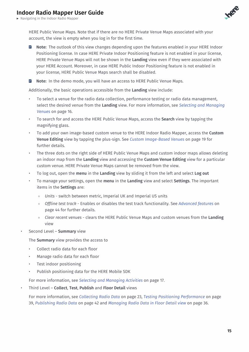
Selecting and Managing VenuesThe figure below shows a sample Landing view when there are HERE Private Venue Maps associated withyour HERE Account (HERE Vancouver, POC Hermia 6, POC Tampere University of Technology). Also, the viewshows that you have accessed a HERE Public Venue Map (Dubai Mall) and imported your own custom venueto the tool (my own venue).
Figure 3: Exemplary Landing View
The Landing view may contain the following items:
• HERE Private Venue Maps (like the HERE Vancouver, POC Hermia 6 and POC Tampere University ofTechnology in the sample above)
To have a HERE Private Venue Map added to your HERE Account, please contact your HERErepresentative. When a new HERE Private Venue Map has been added to your account, log out and log into see the new HERE Private Venue Map in the Landing view.
You cannot remove HERE Private Venue Maps from the Landing view.
• HERE Public Venue Maps (like the Dubai Mall Venue Map in the sample above)
To add a HERE Public Venue Map from the HERE Public Venue Map database to the Landing view, tap thesearch icon (magnifying glass) and enter a search term.
You can remove HERE Public Venue Maps from the Landing view through the Venue editing menu. Notethat this does not delete the radio data collected for the venue.
• Custom image-based venues (like the my own venue in the sample above)
To import your own image-based custom venue map, tap the plus icon. For more information, seeImporting Custom Indoor Maps.
Indoor Radio Mapper User Guide► Navigating in the Indoor Radio Mapper
17
You can remove custom venues from the Landing view through the Venue editing menu. If you haveradio data collected for your custom venue, you will be required to confirm the deletion of the wholevenue incuding any collected radio data.
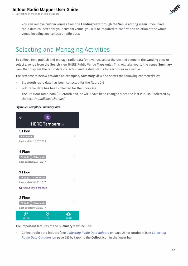
Selecting and Managing ActivitiesTo collect, test, publish and manage radio data for a venue, select the desired venue in the Landing view orselect a venue from the Search view (HERE Public Venue Maps only). This will take you to the venue Summaryview that displays the radio data collection and testing status for each floor in a venue.
The screenshot below provides an examplary Summary view and shows the following characteristics:
• Bluetooth radio data has been collected for the floors 2-5
• WiFi radio data has been collected for the floors 2-4
• The 3rd floor radio data (Bluetooth and/or WiFi) have been changed since the last Publish (indicated bythe text Unpublished changes)
Figure 4: Exemplary Summary view
The important features of the Summary view include:
• Collect radio data indoors (see Collecting Radio Data Indoors on page 26) or outdoors (see CollectingRadio Data Outdoors on page 28) by tapping the Collect icon in the lower bar
Indoor Radio Mapper User Guide► Navigating in the Indoor Radio Mapper
18
• Manage the collected radio data on the floor level (see Floor Radio Data Management on page 37) bytapping the floor
• Test the positioning performance (see Testing for Performance) after the radio data collection by tappingthe Test icon in the lower bar
• Publish the radio data (see Publishing Flow on page 43) to be consumed by the HERE Mobile SDK bytapping the Publish icon in the lower bar
Note: Please note that this is a necessary step before the HERE Mobile SDK is able to locate itselfindoors
Indoor Radio Mapper User Guide► Custom Image-Based Venues
19
Chapter 4Custom Image-Based VenuesTopics:
• Prerequisites for Using Cu...• Importing Custom Indoor Ma...• Manual Calibration
The following section provides information on using your owncustom image-based venues in HERE Indoor Radio Mapper. The toolallows you to import, align and use your own custom image-basedindoor maps for the radio data collection and positioning testing.
Indoor Radio Mapper User Guide► Custom Image-Based Venues
20
Prerequisites for Using Custom Image-based IndoorMapsThe prerequisites for using your own custom image-based indoor maps in HERE Indoor Radio Mapper are
• You have one image per floor in one of the supported formats. HERE Indoor Radio Mapper supports atleast .bmp, .gif, .jpeg and .png image formats.
Note: Each image needs to describe the floor without any tilting and stretching.
Note: If the dimensions of the image are greater than 2048px but smaller than 4096px, HEREIndoor Radio Mapper will downscale the image to 2048px in the largest dimension. Larger imagesare not accepted.
Note: The image needs to have the same scale in both directions, i.e. one pixel must correspondto the same number of meters in all the directions
Note: Radio data collection should be performed in all the floors between the lowest and thehighest floors you are interested in. For example, assume your building has six floors, but youare only interested in positioning in floors 3 and 5. In this case, it is advisable to also import theimage for the floor 4 and perform radio data collection also in that floor in order to have smoothfloor changes, when moving between the floors.
• It is recommend to use an image processing software to make the area outside of the buildingtransparent in the image. This will make it easier to align the image on the HERE Map or satellite images.
• You have copied the custom indoor map images to your device
Note: Copy your indoor map images directly to an arbitrary folder in the device as described inTransferring and Installing HERE Indoor Radio Mapper. Alternatively, you may send the images asan email attachment and save them to a folder in the device.
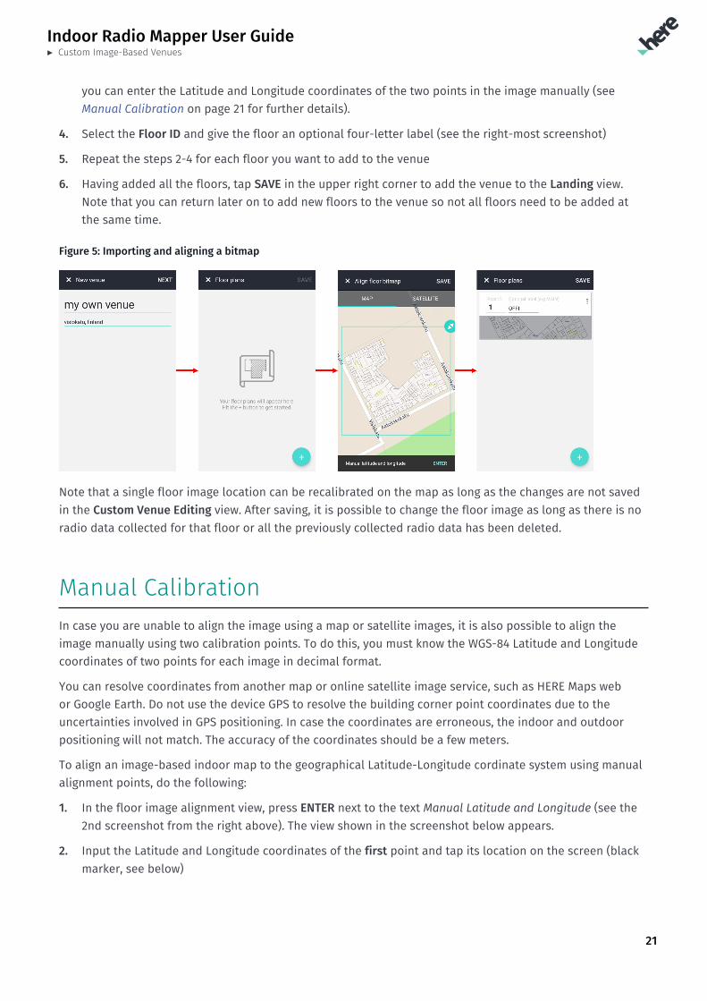
Importing Custom Indoor Maps1. Tap the + icon in the Landing view to open the dialog to enter the Venue name (left-most screenshot
below). You may also optionally input the address. We will lookup the address in the HERE database,which will help you in aligning the image on the map.
Note: Use as descriptive name as possible. The HERE Mobile SDK Positioning API reports thisname as the building name. You cannot change the building name afterwards.
2. Having completed the naming, you can start adding the floors. Once you tap + in the lower right corner(see the second screenshot from the left), a dialog prompts you to select an image representing the floorplan from the device folders.
3. After selecting the image, you can scale and rotate the image either on the HERE Map or satellite images(see the second screenshot from the right). When done, tap SAVE in the upper right corner. Alternatively,
Indoor Radio Mapper User Guide► Custom Image-Based Venues
21
you can enter the Latitude and Longitude coordinates of the two points in the image manually (seeManual Calibration on page 21 for further details).
4. Select the Floor ID and give the floor an optional four-letter label (see the right-most screenshot)
5. Repeat the steps 2-4 for each floor you want to add to the venue
6. Having added all the floors, tap SAVE in the upper right corner to add the venue to the Landing view.Note that you can return later on to add new floors to the venue so not all floors need to be added atthe same time.
Figure 5: Importing and aligning a bitmap
Note that a single floor image location can be recalibrated on the map as long as the changes are not savedin the Custom Venue Editing view. After saving, it is possible to change the floor image as long as there is noradio data collected for that floor or all the previously collected radio data has been deleted.
Manual CalibrationIn case you are unable to align the image using a map or satellite images, it is also possible to align theimage manually using two calibration points. To do this, you must know the WGS-84 Latitude and Longitudecoordinates of two points for each image in decimal format.
You can resolve coordinates from another map or online satellite image service, such as HERE Maps webor Google Earth. Do not use the device GPS to resolve the building corner point coordinates due to theuncertainties involved in GPS positioning. In case the coordinates are erroneous, the indoor and outdoorpositioning will not match. The accuracy of the coordinates should be a few meters.
To align an image-based indoor map to the geographical Latitude-Longitude cordinate system using manualalignment points, do the following:
1. In the floor image alignment view, press ENTER next to the text Manual Latitude and Longitude (see the2nd screenshot from the right above). The view shown in the screenshot below appears.
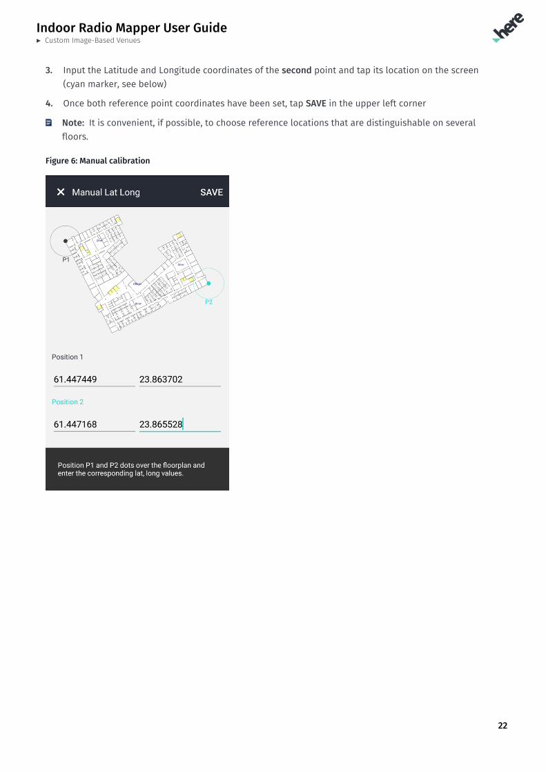
2. Input the Latitude and Longitude coordinates of the first point and tap its location on the screen (blackmarker, see below)
Indoor Radio Mapper User Guide► Custom Image-Based Venues
22
3. Input the Latitude and Longitude coordinates of the second point and tap its location on the screen(cyan marker, see below)
4. Once both reference point coordinates have been set, tap SAVE in the upper left corner
Note: It is convenient, if possible, to choose reference locations that are distinguishable on severalfloors.
Figure 6: Manual calibration
Indoor Radio Mapper User Guide► Collecting Radio Data
23
Chapter 5Collecting Radio DataTopics:
• Collect Data View• How to Collect Radio Data• Collecting Radio Data Indo...• Collecting Radio Data in C...• Collecting Radio Data Outd...• Collecting Radio Data With...• Showing the Data Collected...• Automated Radio Data Quali...
The following section provides information on how to collect radiodata by using HERE Indoor Radio Mapper.
The radio data collection is a prerequisite for indoor positioning.The collected radio data is processed in the HERE Cloud to create anunderstanding, a radiomap, of the radio environment in the venue.This radiomap is then used in the positioning phase by the HEREMobile SDK to locate the location-aware application.
Indoor Radio Mapper User Guide► Collecting Radio Data
24
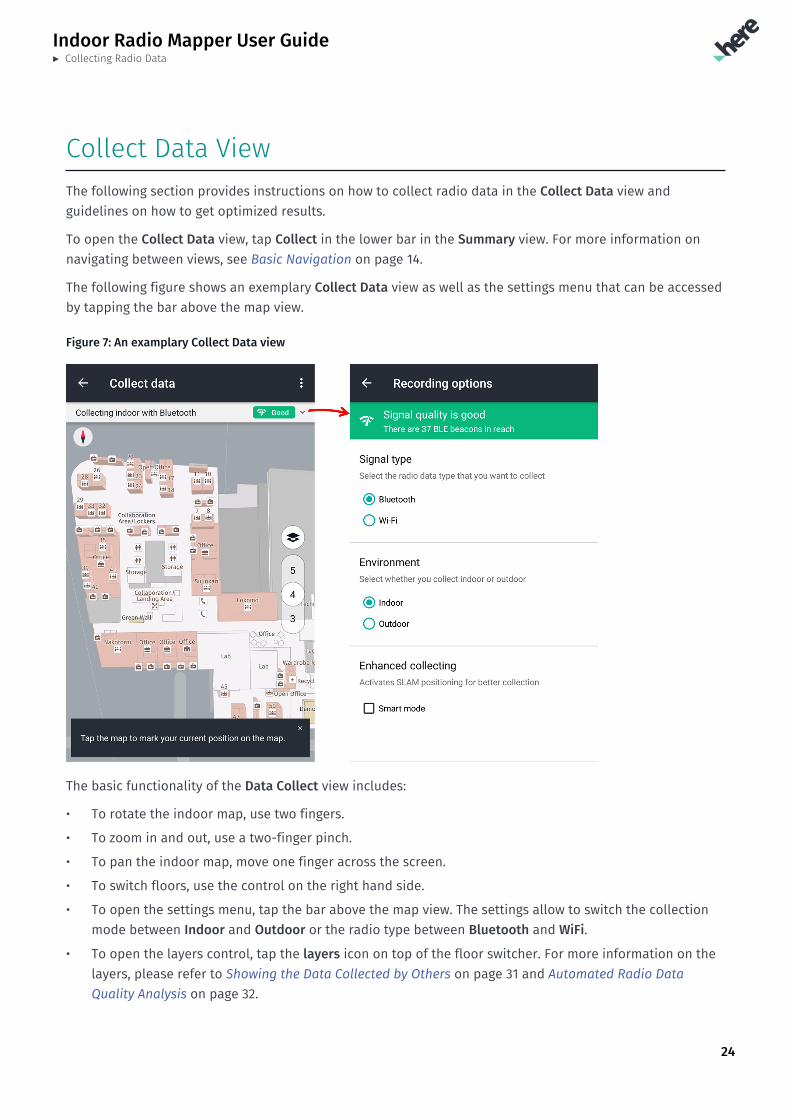
Collect Data ViewThe following section provides instructions on how to collect radio data in the Collect Data view andguidelines on how to get optimized results.
To open the Collect Data view, tap Collect in the lower bar in the Summary view. For more information onnavigating between views, see Basic Navigation on page 14.
The following figure shows an exemplary Collect Data view as well as the settings menu that can be accessedby tapping the bar above the map view.
Figure 7: An examplary Collect Data view
The basic functionality of the Data Collect view includes:
• To rotate the indoor map, use two fingers.
• To zoom in and out, use a two-finger pinch.
• To pan the indoor map, move one finger across the screen.
• To switch floors, use the control on the right hand side.
• To open the settings menu, tap the bar above the map view. The settings allow to switch the collectionmode between Indoor and Outdoor or the radio type between Bluetooth and WiFi.
• To open the layers control, tap the layers icon on top of the floor switcher. For more information on thelayers, please refer to Showing the Data Collected by Others on page 31 and Automated Radio DataQuality Analysis on page 32.
Indoor Radio Mapper User Guide► Collecting Radio Data
25
An important feature of the Data Collect view is the real-time quality indicator in the bar above the mapview. The indicator continuously measures the radio environment (amount of access points, signal strengths)to understand, if there are enough WiFi or Bluetooth signals for high-performance indoor positioning. Theresult is shown as a simple-to-read meter changing color between green (high quality) and red (bad quality).Red indicator means that the radio environment lacks the characteristics to support high quality indoorpositioning and more Bluetooth beacons or access points must be installed.
Note: All the radio data need not be collected in one go. You can always collect more radio data, andthe previously collected radio data gets amended with the newly collected radio data.
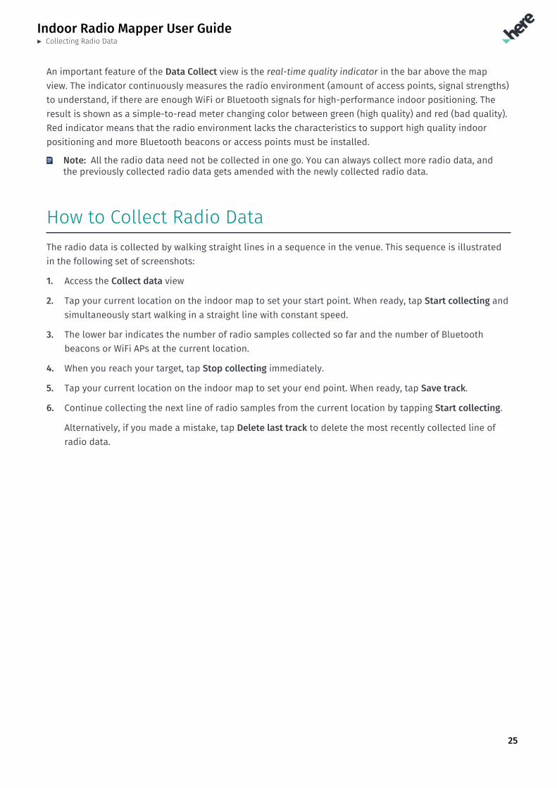
How to Collect Radio DataThe radio data is collected by walking straight lines in a sequence in the venue. This sequence is illustratedin the following set of screenshots:
1. Access the Collect data view
2. Tap your current location on the indoor map to set your start point. When ready, tap Start collecting andsimultaneously start walking in a straight line with constant speed.
3. The lower bar indicates the number of radio samples collected so far and the number of Bluetoothbeacons or WiFi APs at the current location.
4. When you reach your target, tap Stop collecting immediately.
5. Tap your current location on the indoor map to set your end point. When ready, tap Save track.
6. Continue collecting the next line of radio samples from the current location by tapping Start collecting.
Alternatively, if you made a mistake, tap Delete last track to delete the most recently collected line ofradio data.
Indoor Radio Mapper User Guide► Collecting Radio Data
26
Figure 8: The sequence for collecting a line of radio samples
Collecting Radio Data IndoorsDuring the radio data collection, it is important to select the correct floor. In some buildings, such as officebuildings, the floor layouts can resemble each other significantly and, as a consequence, potentially causeconfusion and errors. The more thoroughly you perform the radio data collection, the better the resultingpositioning performance.
To limit the effort of collecting data densely throughout the building, the following guidelines help to obtaingood coverage:
• Main areas, such as main corridors, hallways and main halls have a higher priority; map them first.
• Smaller rooms have lower priority; map them in the second phase.
• In corridors (up to three to five meter width), collect a line of radio data along the both walls. It isadvisable to walk first in one direction along one wall and then in the opposite direction along the otherwall so that both walking directions get covered (this reduces the impact of body shading).
Indoor Radio Mapper User Guide► Collecting Radio Data
27
• Collect radio data in small rooms along the walkable areas. For example, if the room is a small one, i.e.few meters in width, you need to collect only one line of radio data along the center line of the room.It is advisable to collect radio data twice along this line - first in one direction and then to the oppositedirection, when coming back.
• In bigger rooms, collect lines of radio data along the room edges, if the width of the room is moderate(not larger than three to four meters). Again, it is advisable to collect radio data in one direction alongthe first edge and then to the opposite direction along the other edge.
• If the width of the location (room or hall) is larger than four meters, it is advisable to collectmeasurements both along the edges and in the open area. For example, if the width of the location is 10meters, collect data along four lines: along the edges and another two lines three to four meters fromboth edges.
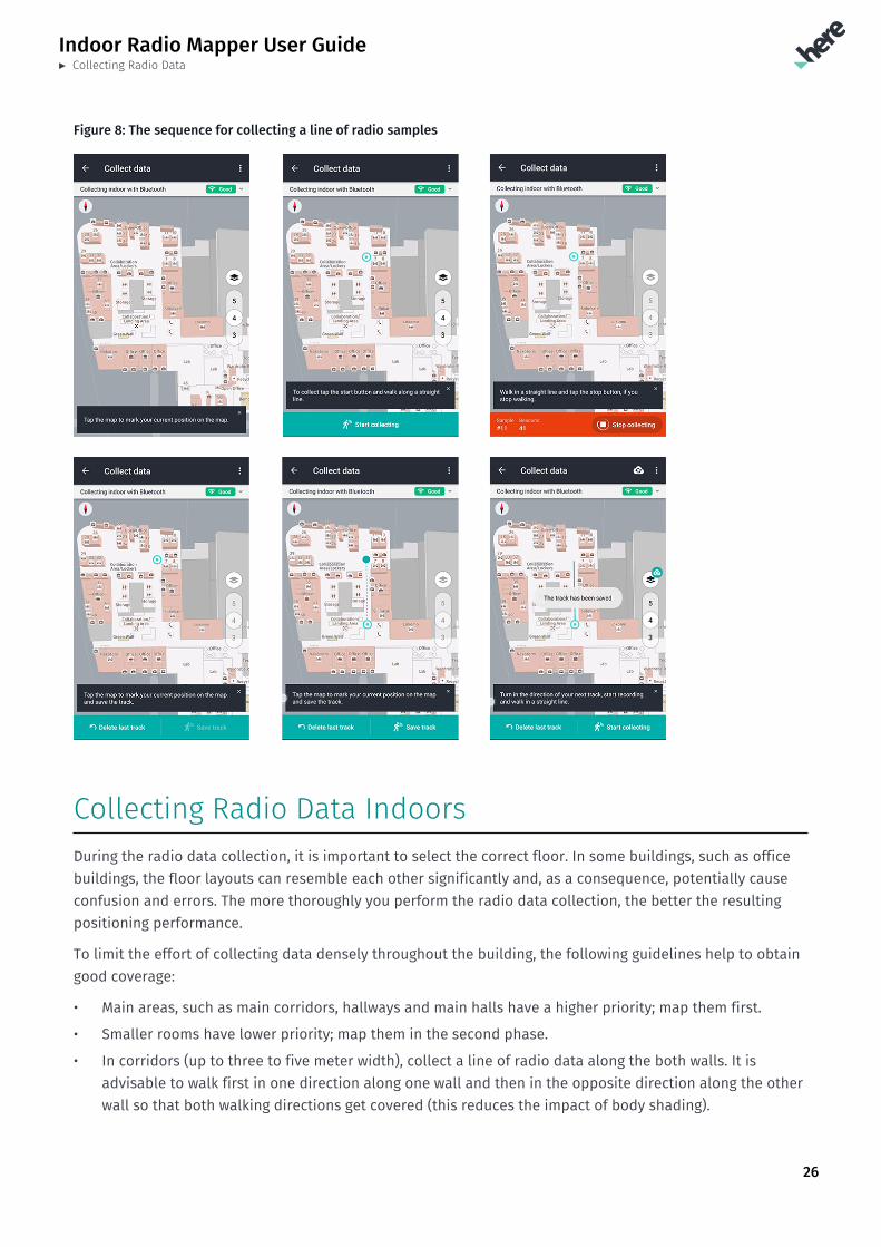
The following figure shows some of the basic principles of the radio data collection:
• In main corridors the radio data has been collected by walking in opposite directions
• Bigger rooms have been circumvented and, where possible, radio data has also been collected in themiddle of the room
• In the passeges to the cubicles the radio data has been collected by walking in both directions
• In smaller rooms radio data has been collected along adjacent walls in opposite directions
Figure 9: Examplary paths for the radio data collection
For information on how to collect radio data in connectors such as staircases and elevators, see CollectingRadio Data in Connectors on page 28.
Indoor Radio Mapper User Guide► Collecting Radio Data
28
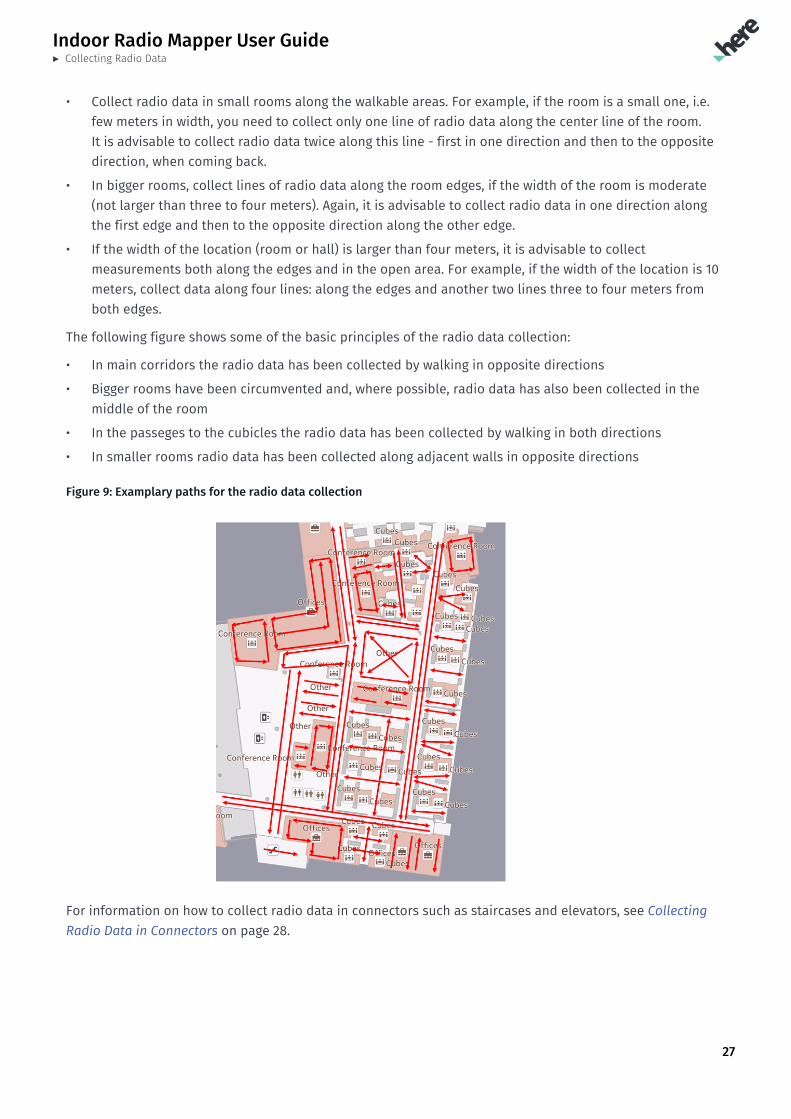
Collecting Radio Data in ConnectorsConnectors are places that connect floors, such as stairs, escalators or elevators. In order to have well-performing floor change behavior, you also need to collect radio samples in the connectors. In case of astaircase or an escalator, you can virtually divide the connector between the two connected floors roughly inthe middle. The figure below shows an example:
Figure 10: Radio sample collection in connectors
When collecting radio data with HERE Indoor Radio Mapper, assign the radio data collected below the redline to the Floor 1 and the radio data collected above the red line to the Floor 2. In case of an elevator,we suggest to take a few radio samples in a stationary elevator in the floor 1 (assigned to the Floor 1)and another set of radio samples in a stationary elevator in the Floor 2 (assigned to the Floor 2). This canbe achieved by keeping the elevator in the 1st floor, starting to record radio samples and then stoppingrecording after a few radio samples. And then moving to the 2nd floor and repeating the same.
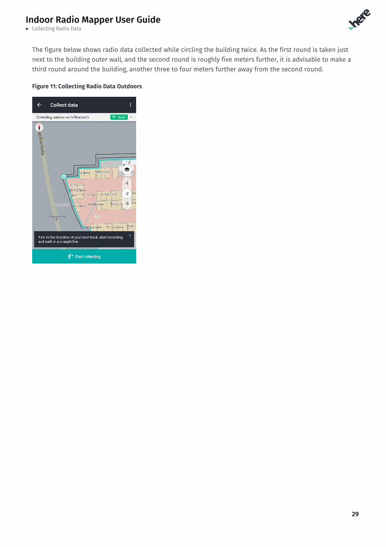
Collecting Radio Data OutdoorsCollecting radio data outdoors is not necessary, if the positioning is to be used indoors only. However, if youwish to have smooth changes between outdoor and indoor positioning methods, it is recommend to performsome radio data collection also along the building perimeter.
Collecting radio data outdoors is similar to collecting radio data indoors with the exception that you do notneed to select a floor. You can freely choose a floor, but it does not have any impact on the end result asthere is only one outdoor floor.
Make sure to observe the following guidelines for optimized results:
• Collect outdoor radio data along the building perimeter.
• Collect radio samples within a 10-meter radius around the building, each time moving between three tofive meters away.
• Change the walking direction after each round.
Indoor Radio Mapper User Guide► Collecting Radio Data
29
The figure below shows radio data collected while circling the building twice. As the first round is taken justnext to the building outer wall, and the second round is roughly five meters further, it is advisable to make athird round around the building, another three to four meters further away from the second round.
Figure 11: Collecting Radio Data Outdoors
Indoor Radio Mapper User Guide► Collecting Radio Data
30
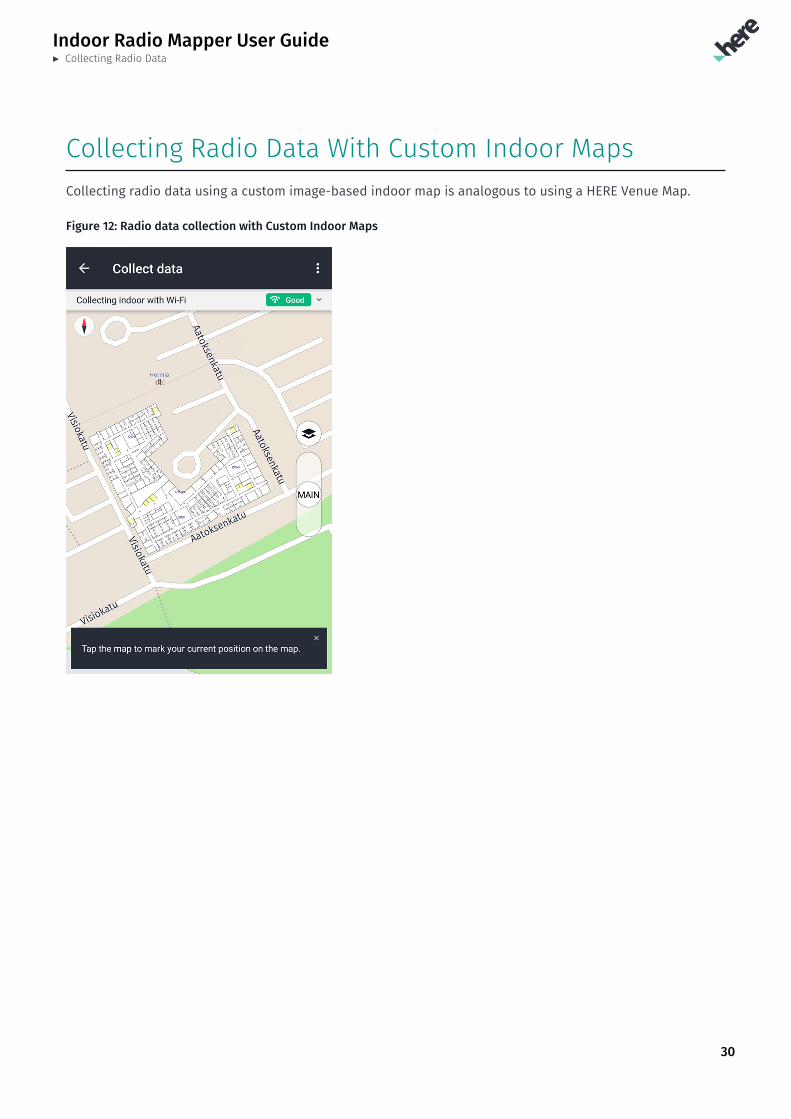
Collecting Radio Data With Custom Indoor MapsCollecting radio data using a custom image-based indoor map is analogous to using a HERE Venue Map.
Figure 12: Radio data collection with Custom Indoor Maps
Indoor Radio Mapper User Guide► Collecting Radio Data
31
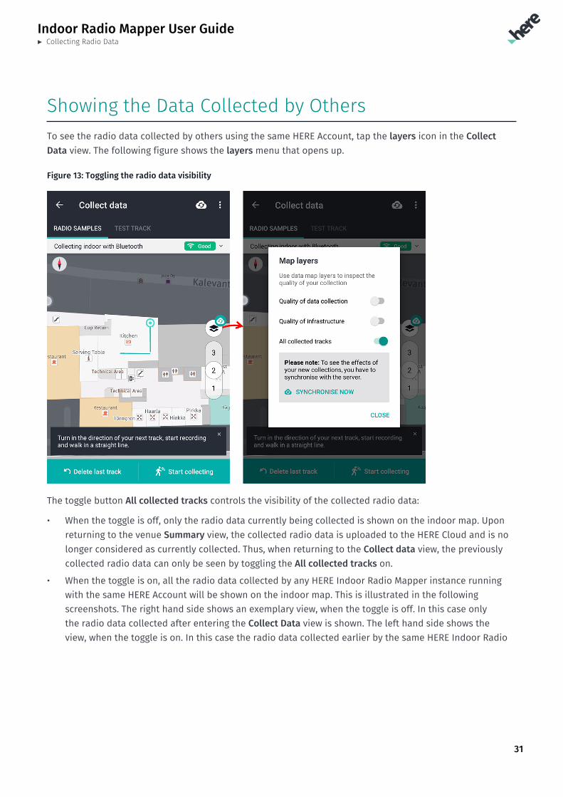
Showing the Data Collected by OthersTo see the radio data collected by others using the same HERE Account, tap the layers icon in the CollectData view. The following figure shows the layers menu that opens up.
Figure 13: Toggling the radio data visibility
The toggle button All collected tracks controls the visibility of the collected radio data:
• When the toggle is off, only the radio data currently being collected is shown on the indoor map. Uponreturning to the venue Summary view, the collected radio data is uploaded to the HERE Cloud and is nolonger considered as currently collected. Thus, when returning to the Collect data view, the previouslycollected radio data can only be seen by toggling the All collected tracks on.
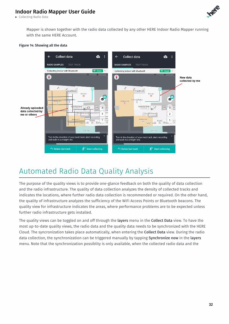
• When the toggle is on, all the radio data collected by any HERE Indoor Radio Mapper instance runningwith the same HERE Account will be shown on the indoor map. This is illustrated in the followingscreenshots. The right hand side shows an exemplary view, when the toggle is off. In this case onlythe radio data collected after entering the Collect Data view is shown. The left hand side shows theview, when the toggle is on. In this case the radio data collected earlier by the same HERE Indoor Radio
Indoor Radio Mapper User Guide► Collecting Radio Data
32
Mapper is shown together with the radio data collected by any other HERE Indoor Radio Mapper runningwith the same HERE Account.
Figure 14: Showing all the data
Automated Radio Data Quality AnalysisThe purpose of the quality views is to provide one-glance feedback on both the quality of data collectionand the radio infrastructure. The quality of data collection analyzes the density of collected tracks andindicates the locations, where further radio data collection is recommended or required. On the other hand,the quality of infrastructure analyzes the sufficiency of the WiFi Access Points or Bluetooth beacons. Thequality view for infrastructure indicates the areas, where performance problems are to be expected unlessfurther radio infrastructure gets installed.
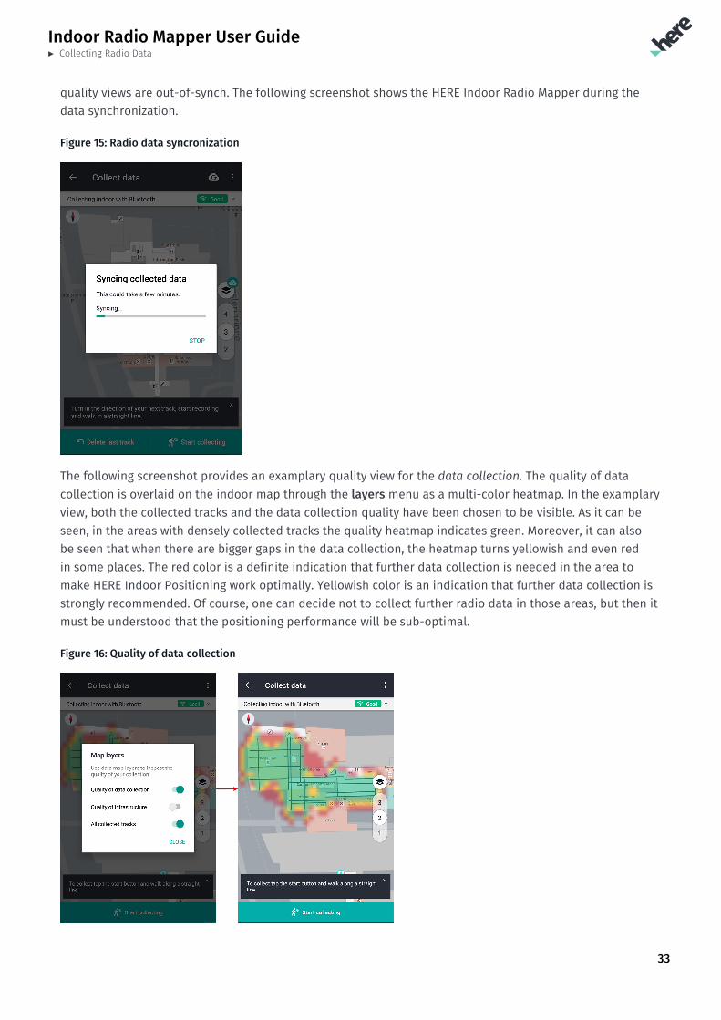
The quality views can be toggled on and off through the layers menu in the Collect Data view. To have themost up-to-date quality views, the radio data and the quality data needs to be synchronized with the HERECloud. The syncronization takes place automatically, when entering the Collect Data view. During the radiodata collection, the synchronization can be triggered manually by tapping Synchronize now in the layersmenu. Note that the synchronization possiblity is only available, when the collected radio data and the
Indoor Radio Mapper User Guide► Collecting Radio Data
33
quality views are out-of-synch. The following screenshot shows the HERE Indoor Radio Mapper during thedata synchronization.
Figure 15: Radio data syncronization
The following screenshot provides an examplary quality view for the data collection. The quality of datacollection is overlaid on the indoor map through the layers menu as a multi-color heatmap. In the examplaryview, both the collected tracks and the data collection quality have been chosen to be visible. As it can beseen, in the areas with densely collected tracks the quality heatmap indicates green. Moreover, it can alsobe seen that when there are bigger gaps in the data collection, the heatmap turns yellowish and even redin some places. The red color is a definite indication that further data collection is needed in the area tomake HERE Indoor Positioning work optimally. Yellowish color is an indication that further data collection isstrongly recommended. Of course, one can decide not to collect further radio data in those areas, but then itmust be understood that the positioning performance will be sub-optimal.
Figure 16: Quality of data collection
Indoor Radio Mapper User Guide► Collecting Radio Data
34
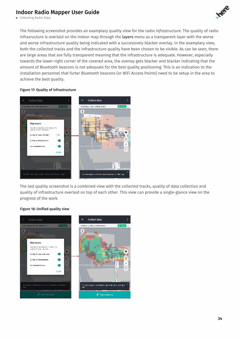
The following screenshot provides an examplary quality view for the radio infrastructure. The quality of radioinfrasructure is overlaid on the indoor map through the layers menu as a transparent layer with the worseand worse infrastructure quality being indicated with a successively blacker overlay. In the examplary view,both the collected tracks and the infrastructure quality have been chosen to be visible. As can be seen, thereare large areas that are fully transparent meaning that the infrastructure is adequate. However, especiallytowards the lower-right corner of the covered area, the overlay gets blacker and blacker indicating that theamount of Bluetooth beacons is not adequate for the best quality positioning. This is an indication to theinstallation personnel that furter Bluetooth beacons (or WiFi Access Points) need to be setup in the area toachieve the best quality.
Figure 17: Quality of infrastructure
The last quality screenshot is a combined view with the collected tracks, quality of data collection andquality of infrastructure overlaid on top of each other. This view can provide a single-glance view on theprogress of the work.
Figure 18: Unified quality view
Indoor Radio Mapper User Guide► Collecting Radio Data
35
Note: If you have doubts regarding the sufficiency of the radio infrastructure in the venue you aremapping, you should consider first doing a very coarse radiomapping, i.e. not following the datacollection guidelines rigorously, but just collecting data along e.g. the main corridors. Having donethis, examine the quality of radio infrastructure to see, if the radio infra is sufficient.
Alternatively, you can walk around the venue with the Collect Data view open and observe the real-time infrastructure quality indicator in the bar above the map view. When the indicator is green, theradio environment is very likely sufficient for high performance indoor positioning. On the other hand,when the indicator is red, high performance indoor positioning is not possible with the current radioinfrasructure.
If the radio environment seems adequate, you can proceed to do the rigorous radio data collection asinstructed in Collecting Radio Data Indoors on page 26. However, if the radio infrastructure seemsto be inadequate, you should consider deploying more Bluetooth beacons or WiFi Access Points in theaffected areas.
Indoor Radio Mapper User Guide► Managing Radio Data in Floor Detail view
36
Chapter 6Managing Radio Data in Floor DetailviewTopics:
• Floor Radio Data Managemen...• Storing Collected Radio Da...
The following section provides information on how to manage thecollected radio data in the HERE Indoor Radio Mapper.
Indoor Radio Mapper User Guide► Managing Radio Data in Floor Detail view
37
Floor Radio Data ManagementThe radio data management refers to managing the radio data collected for your HERE Account. The radiodata management for each floor is accessed from the Summary view. When tapping a floor for which radiodata has been collected, you will be shown the Floor Detail view that includes a list of the collected radiodata sets.
The basic concepts of the radio data management are:
• The changes made in this view only affect the draft radiomap, which can be tested in the Test view.The changes are reflected to the HERE Mobile SDK only when you publish the radio data. For furtherinformation on publishing, please see Publishing Flow on page 43. Additional information on theradiomaps and data flows in general can be found in the HERE Indoor Positioning Installation Guide.
• Any changes made will be reflected to the HERE Cloud and from there to the other HERE Indoor RadioMapper instances running on the same HERE Account. Note that the conflict resolution is simply basedon the latest change winning.
• When publishing, all the enabled radio data sets end up to be used by the HERE Mobile SDK
• A new radio data set appears in the Floor Detail view every time you collect new radio data in the CollectData view and return to the Summary view. This is the smallest entity of radio data that can be managedin the HERE Indoor Radio Mapper.
The basic operations that can be done in the management view are:
• See which radio data sets have been published for use by the HERE Mobile SDK, and which are stillunpublished
• Disable radio data sets from use (only the draft radiomap is affected)
• Enable radio data sets back into use (only the draft radiomap is affected)
• Delete radio data sets (only un-published ones can be deleted)
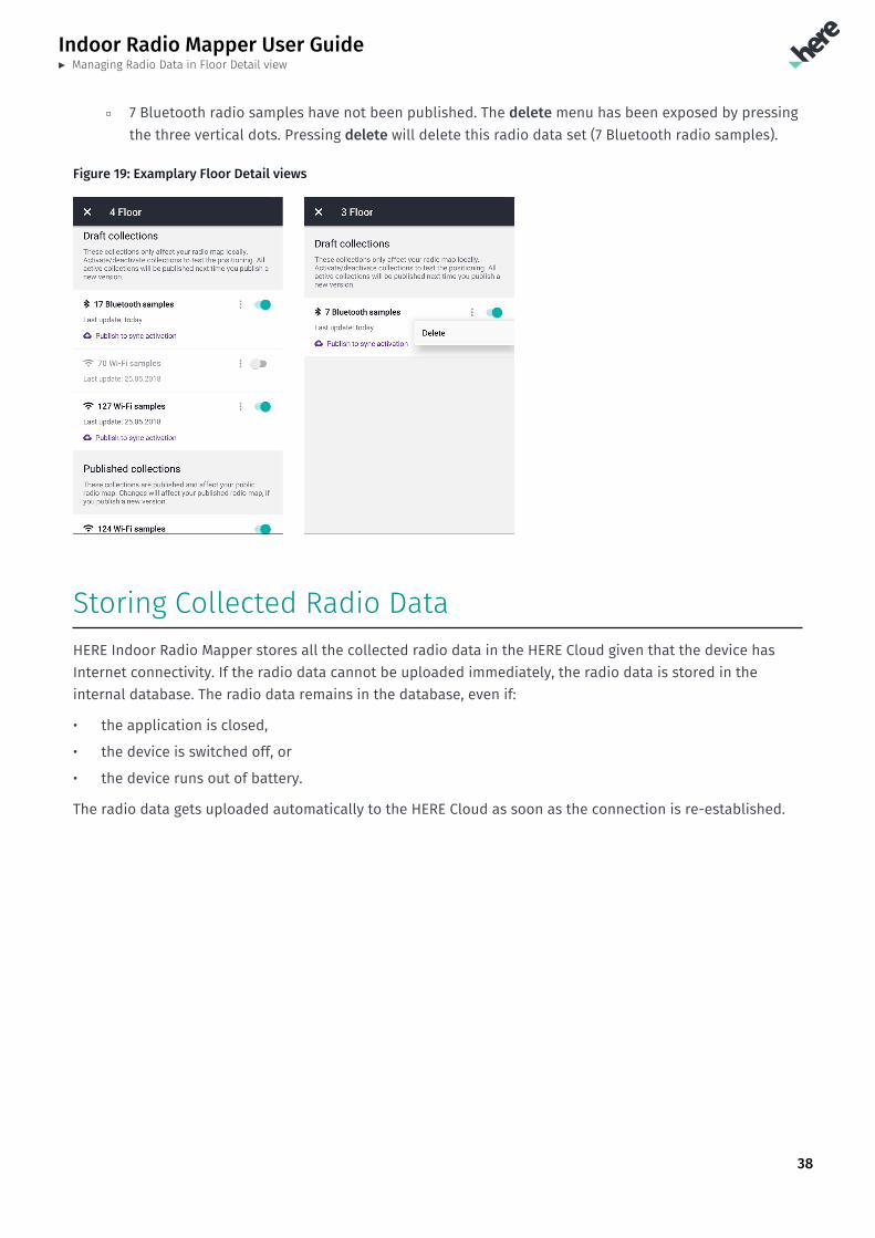
The following figure shows exemplary Floor Detail views for two floors. The following remarks can be made:
• For the 4th floor
▫ 17 Bluetooth radio samples are only in the draft radiomap, not usable by the HERE Mobile SDK
▫ 70 WiFi radio samples have been disabled from the use totally
▫ 127 WiFi radio samples are only in the draft radiomap, not usable by the HERE Mobile SDK
▫ 124 WiFi radio samples are both in the draft radiomap and also published for the HERE Mobile SDK
• For the 3rd floor
Indoor Radio Mapper User Guide► Managing Radio Data in Floor Detail view
38
▫ 7 Bluetooth radio samples have not been published. The delete menu has been exposed by pressingthe three vertical dots. Pressing delete will delete this radio data set (7 Bluetooth radio samples).
Figure 19: Examplary Floor Detail views
Storing Collected Radio DataHERE Indoor Radio Mapper stores all the collected radio data in the HERE Cloud given that the device hasInternet connectivity. If the radio data cannot be uploaded immediately, the radio data is stored in theinternal database. The radio data remains in the database, even if:
• the application is closed,
• the device is switched off, or
• the device runs out of battery.
The radio data gets uploaded automatically to the HERE Cloud as soon as the connection is re-established.
Indoor Radio Mapper User Guide► Testing Positioning Performance
39
Chapter 7Testing Positioning PerformanceTopics:
• Testing Positioning Real-T...
The following section provides information on how to conductperformance testing with HERE Indoor Radio Mapper.
Indoor Radio Mapper User Guide► Testing Positioning Performance
40
Testing Positioning Real-TimeThe prerequisite for testing is collecting radio data at the venue. After the radio data upload the HERE Cloud,it takes some minutes before the generated radiomap is available for testing. To open the Test view with thelatest positioning data (radiomap) from the HERE Cloud, tap Test in the lower bar of the Summary view. Formore information on navigating between views, see Basic Navigation on page 14.
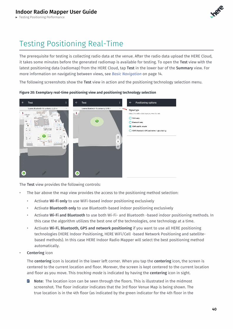
The following screenshots show the Test view in action and the positioning technology selection menu.
Figure 20: Exemplary real-time positioning view and positioning technology selection
The Test view provides the following controls:
• The bar above the map view provides the access to the positioning method selection:
• Activate Wi-Fi only to use WiFi-based indoor positioning exclusively
• Activate Bluetooth only to use Bluetooth-based indoor positioning exclusively
• Activate Wi-Fi and Bluetooth to use both Wi-Fi- and Bluetooth -based indoor positioning methods. Inthis case the algorithm utilizes the best one of the technologies, one technology at a time.
• Activate Wi-Fi, Bluetooth, GPS and network positioning if you want to use all HERE positioningtechnologies (HERE Indoor Positioning, HERE WiFi/Cell -based Network Positioning and satellite-based methods). In this case HERE Indoor Radio Mapper will select the best positioning methodautomatically.
• Centering icon
The centering icon is located in the lower left corner. When you tap the centering icon, the screen iscentered to the current location and floor. Morever, the screen is kept centered to the current locationand floor as you move. This tracking mode is indicated by having the centering icon in sight.
Note: The location icon can be seen through the floors. This is illustrated in the midmostscreenshot. The floor indicator indicates that the 3rd floor Venue Map is being shown. Thetrue location is in the 4th floor (as indicated by the green indicator for the 4th floor in the
Indoor Radio Mapper User Guide► Testing Positioning Performance
41
floor switcher). However, the centering icon at the lower left corner in the midmost screenshotindicates that the location is not being tracked. When you again want to get back to the actualcurrent floor, press the centering icon.
The Test view provides the following information:
• Source
Indicates the technology used for the location determination, and is one of Bluetooth, Wi-Fi, Wi-Fioutdoor, Cellular or GPS.
• Uncertainty
Indicates the estimated location uncertainty in meters. Note that uncertainty is different from error oraccuracy. Uncertainty is a statistical quantity expressing, how well the measurements and the radiomapmatch at the current location. The better the match, the lower the uncertainty - and vice versa.
Indoor Radio Mapper User Guide► Publishing Radio Data
42
Chapter 8Publishing Radio DataTopics:
• Publishing Flow
The following section provides details on publishing the radiodata for use by the HERE Mobile SDK. The radio data needs to bepublished before it can be used by the HERE Mobile SDK.
Note that publishing to the HERE Mobile SDK requires that you haveregistered for the HERE Mobile SDK evaluation or have a commerciallicense. The registration to the evaluation is done at the HEREDeveloper Portal.
Indoor Radio Mapper User Guide► Publishing Radio Data
43
Publishing FlowWhenever radio data is being collected or a radio data set state is changed between enabled and disabledin the Floor Detail view (see Floor Radio Data Management on page 37), the operations affect only the draftradiomap. The basic idea is that radio data can be modified and tested freely in HERE Indoor Radio Mapperand the changes are not reflected to the production before the radio data is published. Note that when youtest positioning with HERE Indoor Radio Mapper, you are always testing the positioning performance usingthe draft radiomap. Thus, before HERE Mobile SDK sees the same radio data as you test in HERE Indoor RadioMapper, you need to publish the radio data.
Publishing means synchronizing the draft radiomap to the production. Any radio data sets, publishedor unpublished, that are enabled in the per-floor Floor Detail view are published, when the publish iscommenced in the Publish view. Vice versa, any disabled radio data sets, published or unpublished, areremoved from the production upon publish. Please refer to HERE Indoor Positioning Installation Guide fordetailed explanation on the draft and published (production) radiomaps.
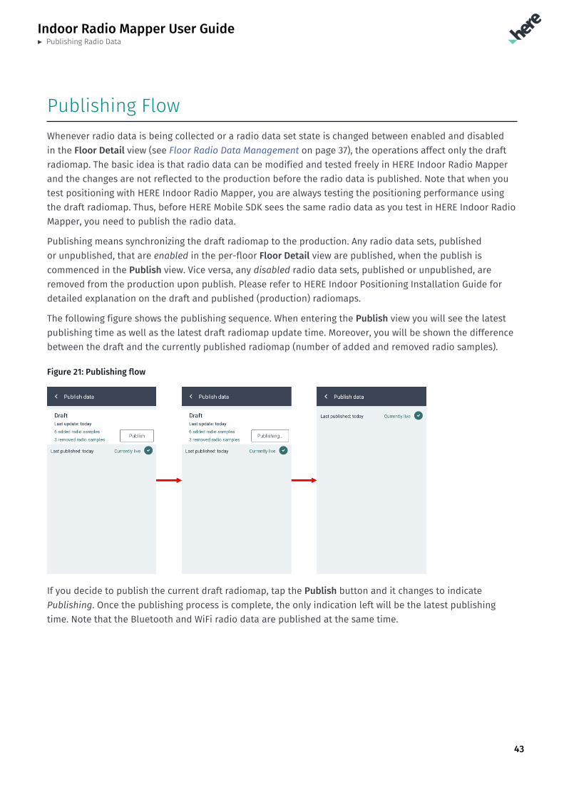
The following figure shows the publishing sequence. When entering the Publish view you will see the latestpublishing time as well as the latest draft radiomap update time. Moreover, you will be shown the differencebetween the draft and the currently published radiomap (number of added and removed radio samples).
Figure 21: Publishing flow
If you decide to publish the current draft radiomap, tap the Publish button and it changes to indicatePublishing. Once the publishing process is complete, the only indication left will be the latest publishingtime. Note that the Bluetooth and WiFi radio data are published at the same time.
Indoor Radio Mapper User Guide► Advanced features
44
Chapter 9Advanced featuresTopics:
• Collecting Test Tracks• Running a Test Track• SLAM Mode for Radio Data C...
The following section provides information on the HERE IndoorRadio Mapper advanced features.
Indoor Radio Mapper User Guide► Advanced features
45
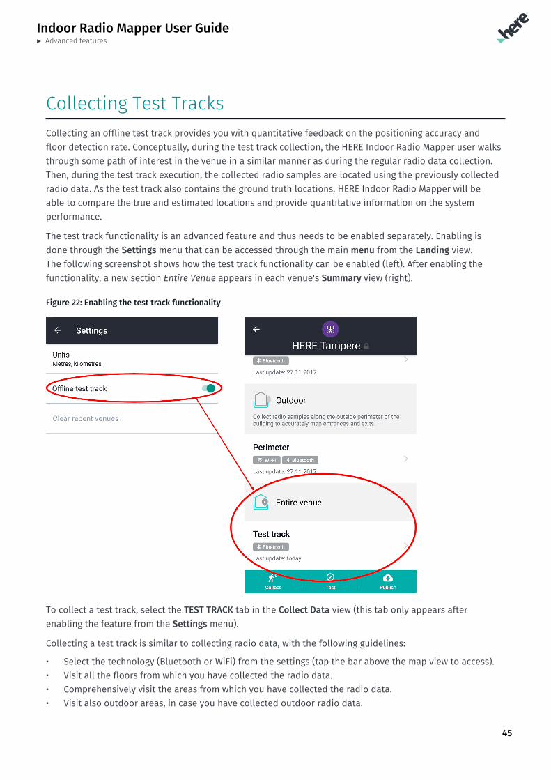
Collecting Test TracksCollecting an offline test track provides you with quantitative feedback on the positioning accuracy andfloor detection rate. Conceptually, during the test track collection, the HERE Indoor Radio Mapper user walksthrough some path of interest in the venue in a similar manner as during the regular radio data collection.Then, during the test track execution, the collected radio samples are located using the previously collectedradio data. As the test track also contains the ground truth locations, HERE Indoor Radio Mapper will beable to compare the true and estimated locations and provide quantitative information on the systemperformance.
The test track functionality is an advanced feature and thus needs to be enabled separately. Enabling isdone through the Settings menu that can be accessed through the main menu from the Landing view.The following screenshot shows how the test track functionality can be enabled (left). After enabling thefunctionality, a new section Entire Venue appears in each venue's Summary view (right).
Figure 22: Enabling the test track functionality
To collect a test track, select the TEST TRACK tab in the Collect Data view (this tab only appears afterenabling the feature from the Settings menu).
Collecting a test track is similar to collecting radio data, with the following guidelines:
• Select the technology (Bluetooth or WiFi) from the settings (tap the bar above the map view to access).• Visit all the floors from which you have collected the radio data.• Comprehensively visit the areas from which you have collected the radio data.• Visit also outdoor areas, in case you have collected outdoor radio data.
Indoor Radio Mapper User Guide► Advanced features
46
• As the test track needs to be continuous, you need to continue the track always from the end point ofthe previous segment.
• When changing from indoors to outdoors, or vice versa, remember to change to indoor/outdoor modefrom the settings (tap the bar above the map view to access).
• Test track can be finished at any point once you have covered all the applicable areas.
You can only collect one test track per building for each technology, i.e. you can have one test track forBluetooth and the other one for Wi-Fi. You can delete a test track by tapping the Test Track in the Summaryview.
You can collect a test track with less density than radio samples. For example, when collecting a test trackin a corridor, instead of collecting a line of radio data along the opposite walls (as you should do whencollecting radio samples), you can collect a test track simply along the center line. The same applies torooms and other areas.
For information on running the test track to obtain quantitative information on the HERE Indoor Positioningperformance at your venue, please see Running a Test Track on page 46.
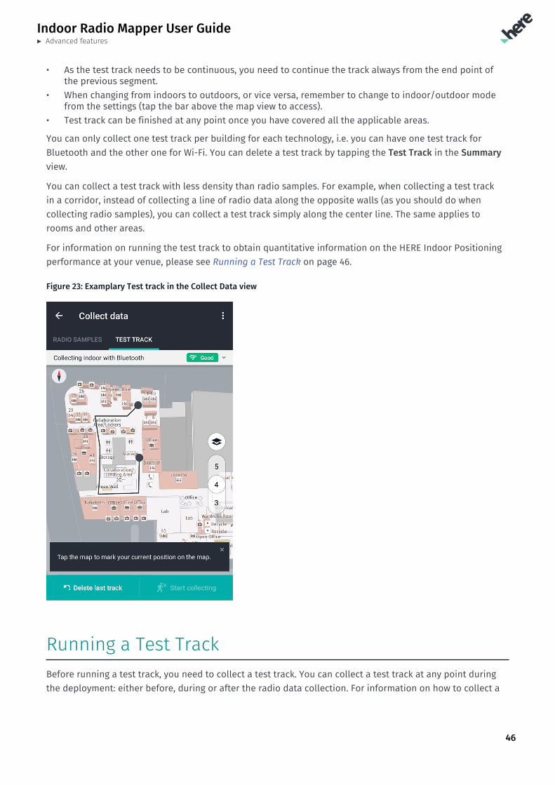
Figure 23: Examplary Test track in the Collect Data view
Running a Test TrackBefore running a test track, you need to collect a test track. You can collect a test track at any point duringthe deployment: either before, during or after the radio data collection. For information on how to collect a
Indoor Radio Mapper User Guide► Advanced features
47
test track, see Collecting Test Tracks on page 45. However, you can only run the test track after the radiodata collection.
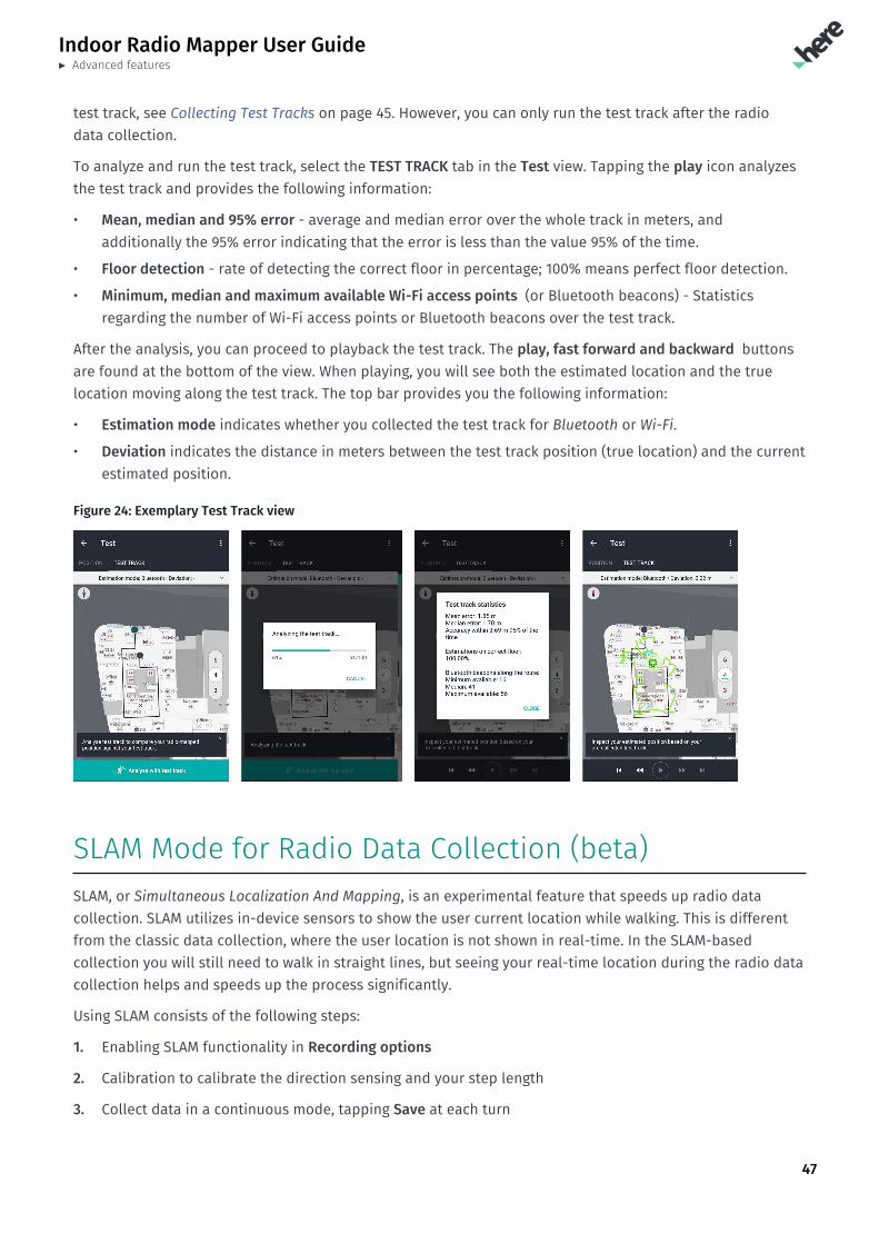
To analyze and run the test track, select the TEST TRACK tab in the Test view. Tapping the play icon analyzesthe test track and provides the following information:
• Mean, median and 95% error - average and median error over the whole track in meters, andadditionally the 95% error indicating that the error is less than the value 95% of the time.
• Floor detection - rate of detecting the correct floor in percentage; 100% means perfect floor detection.
• Minimum, median and maximum available Wi-Fi access points (or Bluetooth beacons) - Statisticsregarding the number of Wi-Fi access points or Bluetooth beacons over the test track.
After the analysis, you can proceed to playback the test track. The play, fast forward and backward buttonsare found at the bottom of the view. When playing, you will see both the estimated location and the truelocation moving along the test track. The top bar provides you the following information:
• Estimation mode indicates whether you collected the test track for Bluetooth or Wi-Fi.
• Deviation indicates the distance in meters between the test track position (true location) and the currentestimated position.
Figure 24: Exemplary Test Track view
SLAM Mode for Radio Data Collection (beta)SLAM, or Simultaneous Localization And Mapping, is an experimental feature that speeds up radio datacollection. SLAM utilizes in-device sensors to show the user current location while walking. This is differentfrom the classic data collection, where the user location is not shown in real-time. In the SLAM-basedcollection you will still need to walk in straight lines, but seeing your real-time location during the radio datacollection helps and speeds up the process significantly.
Using SLAM consists of the following steps:
1. Enabling SLAM functionality in Recording options
2. Calibration to calibrate the direction sensing and your step length
3. Collect data in a continuous mode, tapping Save at each turn
Indoor Radio Mapper User Guide► Advanced features
48
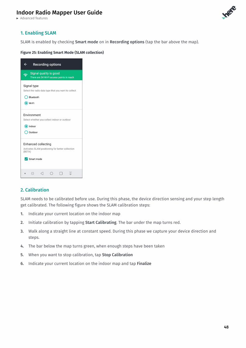
1. Enabling SLAM
SLAM is enabled by checking Smart mode on in Recording options (tap the bar above the map).
Figure 25: Enabling Smart Mode (SLAM collection)
2. Calibration
SLAM needs to be calibrated before use. During this phase, the device direction sensing and your step lengthget calibrated. The following figure shows the SLAM calibration steps:
1. Indicate your current location on the indoor map
2. Initiate calibration by tapping Start Calibrating. The bar under the map turns red.
3. Walk along a straight line at constant speed. During this phase we capture your device direction andsteps.
4. The bar below the map turns green, when enough steps have been taken
5. When you want to stop calibration, tap Stop Calibration
6. Indicate your current location on the indoor map and tap Finalize
Indoor Radio Mapper User Guide► Advanced features
49
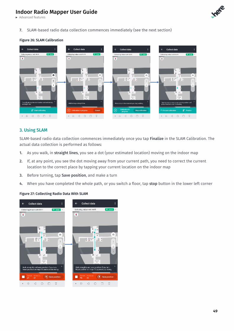
7. SLAM-based radio data collection commences immediately (see the next section)
Figure 26: SLAM Calibration
3. Using SLAM
SLAM-based radio data collection commences immediately once you tap Finalize in the SLAM Calibration. Theactual data collection is performed as follows:
1. As you walk, in straight lines, you see a dot (your estimated location) moving on the indoor map
2. If, at any point, you see the dot moving away from your current path, you need to correct the currentlocation to the correct place by tapping your current location on the indoor map
3. Before turning, tap Save position, and make a turn
4. When you have completed the whole path, or you switch a floor, tap stop button in the lower left corner
Figure 27: Collecting Radio Data With SLAM
Indoor Radio Mapper User Guide► FAQ
50
Chapter 10FAQTopics:
• Why do I have to walk in s...• Why do I need to align my ...• Are there any device setti...
The following section lists frequently asked questions and providesuseful answers.
Indoor Radio Mapper User Guide► FAQ
51
Why do I have to walk in straight lines at constantspeed?HERE Indoor Radio Mapper interpolates the collected radio samples between the start and end points youindicate on the floor plan. Because HERE Indoor Radio Mapper does not know about your walking speedor any turns that you make, the tool assumes that you walked in a straight line from the start to the end atconstant speed. This assumption allows the HERE Indoor Radio Mapper to divide the radio samples evenlyalong that line.
Why do I need to align my own custom indoor maps toLatitude and Longitude coordinates?Alignment serves two purposes:
1. To understand the dimensions of the building, in meters. This is important for HERE Indoor Positioningto function correctly.
2. When we switch from indoor positioning to outdoor positioning, having both indoor and outdoor maps inthe same coordinate system is the only way to ensure smooth transition.
Are there any device settings that I should be awareof?The latest Android devices have an advanced option that allows measuring the WiFi and Bluetooth radiosignals even when the radios are turned off. HERE Indoor Radio Mapper benefits from enabling this option.
In Samsung devices these settings can be found through Settings -> Location -> Improve accuracy. The menuhas the setting separately for WiFi and Bluetooth. HERE Indoor Radio Mapper queries these settings to beenabled, if not already enabled.
When this setting is enabled for WiFi, HERE Indoor Radio Mapper switches the WiFi connectivity off, whencollecting WiFi radio data to ensure the best measurement quality. Similarly, when this setting is enabledfor Bluetooth, HERE Indoor Radio Mapper switches the Bluetooth connectivity off, when collecting Bluetoothradio data to ensure the best measurement quality.