Embed Size (px)
Citation preview
Indoor Autonomous Navigation of Low-Cost MAVsUsing Landmarks and 3D Perception
Ludovic APVRILLEInstitut Mines-Telecom
Telecom ParisTech, CNRS/LTCICampus SophiaTech, 450 Route des Chappes,
06410 Biot, FRANCEEmail : [email protected]
Jean-Luc DugelayEURECOM
Campus SophiaTech, 450 Route des Chappes,06410 Biot, FRANCE
Email : [email protected]
Benjamin RanftFZI Research Center for Information Technology
Haid-und-Neu-Str. 10-14,76131 Karlsruhe, GERMANY
Email : [email protected]
Abstract—We present an implementation of autonomous nav-igation for Micro Air Vehicles which is well-suited for veryinexpensive models: It relies on a bottom and a front camera,and few additional on-board sensors to solve the challenges offlight planning and collision avoidance. Artificial landmarks maybe used in specific places (lines in narrow corridors) and in placeswith an ambiguous further flight path, such as corridor crossingsor junctions. For the latter case, they thus provide topologicallocalization, which enables our system to perform tasks like waypoint following. Even without any 3D sensor, our system is alsoable to reconstruct metric distances from its monocular cameravia two complementary methods: An oscillating motion pattern issuperimposed to regular flight to reliably estimate up-to-date 3Dpositions of sparse image features. As an alternative, a specificflight maneuver can virtually create a vertical stereo camera toprovide depth information densely across most pixels at singlepoints in time.
Keywords—Drones; UAV; 3D perception;
I. INTRODUCTION
Drones, also knwon as UAV (Unmanned Aerial Vehicle)are flying machines which are remotely controlled. They aregenerally used for surveillance purpose and to sense informa-tion. Drones are currently used for oudoor applications, and,apart from the user interaction, their guidance is GPS-based.Since they are naturally much smaller than regular drones,mini drones are more likely to be used for indoor applications.Unfortunately, the GPS signal can not be efficiently used insidebuildings, and so, mini-drones must permanently be remotelycontrolled, which strongly reduces their interest.Thus, the EURECOM/Telecom ParisTech project calledDrone4u intends to provide mini-drones with automated envi-ronment analysis capabilities. The objective of this analysis isto allow mini-drones to autonomously navigate inside build-ings. Many "new" applications are targetted by autonomousnavigation: guidance of persons in complex buildings (assis-tance to person), inspection of a building after a disaster (e.g.,an earthquake), surveillance activities e.g. to know whether thebuilding of a company is empty before locking it during thenight.Another objective of Drone4u is also to demonstrate that
autonomous navigation can also be performed on low-cost minidrones (e.g., a few hundred euros), therefore with limited videoprocessing capabilities, and cheap sensors. In that context,our work is mainly to invent and implement environmentrecognition algorithms. That recognition is applied in threecontexts:
• To Follow of a colored line located on the floor.
• To identify landmarks located at crossings.
• To capture the environment of the drone in 3 Dimen-sions, with no 3D sensor.
First, the paper presents the general system architecture in nextsection. Then, each above-mentionned recognition schemes isdetailed.
II. SYSTEM ARCHITECTURE
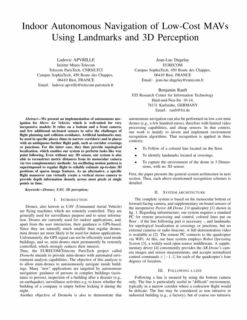
The complete system is based on the monocular bottom orforward-facing camera, and supplementary on-board sensors ofthe inexpensive Parrot AR.Drone 2.0 quadcopter [1] shown infig. 1. Regarding infrastructure, our system requires a standardPC for remote processing and control, colored lines put onfloor - if the line following part is necessary -, and landmarksfor topological localization at crossings or junctions, but noexternal cameras or radio beacons. A full demonstration videois available at [2]. The remote PC connects to the quadcoptervia WiFi. At this, our base system employs Robot OperatingSystem [3], a widely-used open-source middleware. A supple-mentary driver [4] conveniently provides the AR.Drone’s cam-era images and sensor measurements, and accepts normalizedcontrol commands ∈ [−1, 1] for each of the quadcopter’s fourdegrees of freedom.
III. FOLLOWING A LINE
Following a line is ensured by using the bottom cameraonly. The line is particularly useful in "difficult" environment,typically in a narrow corridor where a corkscrew flight wouldbe delicate. The line may be considered as non intrusive inindustrial building (e.g., a factory), but of course too intrusive
remote PC: perception control
bas
e s
yste
m
Sparse / dense3D reconstruction
line recognition
alignment for further flight
“corkscrew” / “change altitude” flight control
“regular” flight
landmark recognition
quadcopter
sens
ors
an
da
ctu
ator
s
on-
bo
ard
pro
cess
ing
WiFi
images, sensorreadings
control
commands
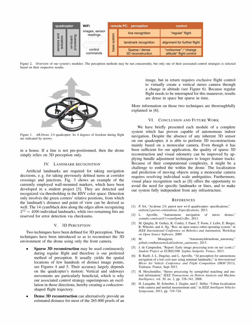
Figure 2. Overview of our system’s modules: The perception methods may be run concurrently, but only one of their associated control strategies is selectedbased on their respective results.
Figure 1. AR.Drone 2.0 quadcopter: Its 4 degrees of freedom during flightare indicated by arrows.
in a house. If a line is not pre-positionned, then the dronesimply relies on 3D perception only.
IV. LANDMARK RECOGNITION
Artificial landmarks are required for taking navigationdecisions, e. g. for taking previously defined turns at corridorcrossings and junctions. Fig. 3 shows an example of thecurrently employed wall-mounted markers, which have beendeveloped in a student project [5]. They are detected andrecognized via thresholding in the HSV color space: Detectiononly involves the green corners’ relative positions, from whichthe landmark’s distance and point of view can be derived aswell. The 14 cyan/black dots along the edges allow recognizing212 = 4096 individual landmarks, while two remaining bits arereserved for error detection via checksums.
V. 3D PERCEPTION
Two techniques have been defined for 3D perception. Thesetechniques have been introduced so as to reconstruct the 3Denvironment of the drone using only the front camera.
• Sparse 3D reconstruction may be used continuouslyduring regular flight and therefore is our preferredmethod of perception. It usually yields the spatiallocations of few hundreds of distinct image points,see Figures 4 and 5. Their accuracy largely dependson the quadcopter’s motion: Vertical and sidewaysmovements are particularly beneficial, which is whyour associated control strategy superimposes an oscil-lation in those directions, hereby creating a corkscrew-shaped flight trajectory.
• Dense 3D reconstruction can alternatively provide anestimated distance for most of the 265.000 pixels of an
image, but in return requires exclusive flight controlto virtually create a vertical stereo camera througha change in altitude (see Figure 6). Because regularflight needs to be interrupted for this maneuver, resultsare dense in space but sparse in time.
More information on those two techniques are throroughfullyexplained in [6].
VI. CONCLUSION AND FUTURE WORK
We have briefly presented each module of a completesystem which has proven capable of autonomous indoornavigation. Despite the absence of any inherent 3D sensoron our quadcopter, it is able to perform 3D reconstructionsmainly based on a monocular camera. Even though it hasbeen sufficient for our application, the quality of sparse 3Dreconstruction and visual odometry can be improved by ap-plying bundle adjustment techniques to longer feature tracks.Because of their computational complexity, it might be achallenge to embed the within the drone. The localizationand prediction of moving objects using a monocular camerarequires resolving individual scale ambiguities. Furthermore,visual place recognition such as [8] offers the opportunity toavoid the need for specific landmarks or lines, and to makeour system fully independent from any infrastructure.
REFERENCES
[1] P. SA, “Ar.drone 2.0. parrot new wi-fi quadricopter- specifications,”ardrone2.parrot.com/ardrone-2/specifications, 2013.
[2] L. Apvrille, “Autonomous navigation of micro drones,”youtube.com/watch?v=tamYpmGvzRw, 2013.
[3] M. Quigley, B. Gerkey, K. Conley, J. Faust, T. Foote, J. Leibs, E. Berger,R. Wheeler, and A. Ng, “Ros: an open-source robot operating system,” inIEEE International Conference on Robotics and Automation, Workshopon Open Source Software, 2009.
[4] M. Monajjemi, “Autonomylab/ardrone_autonomy,”github.com/AutonomyLab/ardrone_autonomy, 2013.
[5] J. de Campredon, “Report: Early image processing tests on uav (cont.),”Student Project at EURECOM, Sophia Antipolis, France, 2013.
[6] B. Ranft, J.-L. Dugelay, and L. Apvrille, “3d perception for autonomousnavigation of a low-cost mav using minimal landmarks,” in InternationalMicro Air Vehicle Conference and Flight Competition (IMAV’2013),Toulouse, France, Sept 2013.
[7] H. Hirschmüller, “Stereo processing by semiglobal matching and mu-tual information,” IEEE Transactions on Pattern Analysis and MachineIntelligence, vol. 30, no. 2, pp. 328–341, 2008.
[8] H. Lategahn, M. Schreiber, J. Ziegler, and C. Stiller, “Urban localizationwith camera and inertial measurement unit,” in IEEE Intelligent VehiclesSymposium, 2013, pp. 719–724.
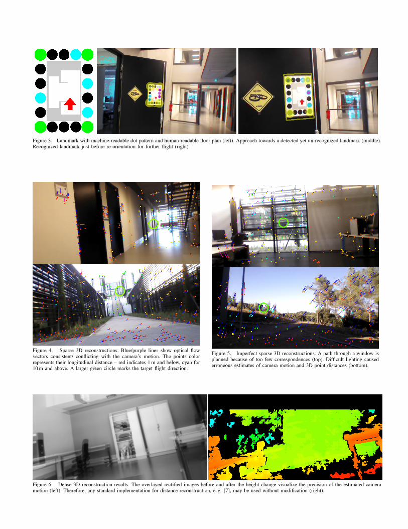
Figure 3. Landmark with machine-readable dot pattern and human-readable floor plan (left). Approach towards a detected yet un-recognized landmark (middle).Recognized landmark just before re-orientation for further flight (right).
Figure 4. Sparse 3D reconstructions: Blue/purple lines show optical flowvectors consistent/ conflicting with the camera’s motion. The points colorrepresents their longitudinal distance – red indicates 1 m and below, cyan for10 m and above. A larger green circle marks the target flight direction.
Figure 5. Imperfect sparse 3D reconstructions: A path through a window isplanned because of too few correspondences (top). Difficult lighting causederroneous estimates of camera motion and 3D point distances (bottom).
Figure 6. Dense 3D reconstruction results: The overlayed rectified images before and after the height change visualize the precision of the estimated cameramotion (left). Therefore, any standard implementation for distance reconstruction, e. g. [7], may be used without modification (right).