Embed Size (px)
Citation preview

Installation and Operation Manual• 100% Outdoor Air Systems & High Outdoor Air Systems
• Aura™ (QS), dedicated outdoor air system, offers a high quality dehumidifier with various options to cover multiple applications
• TotalAire™ (QS), dedicated outdoor air systems, offers an optional energy recovery wheel that recovers both sensible and latent heat.
• VerticalAire™ (QV), dedicated outdoor air system, is a high- quality cost-effective dehumidifier that’s designed for tight spaces
Indoor Air QualityAura™ (QS)TotalAire™ (QS)VerticalAire™ (QV)
TotalAire™ (QS)Dehumidifier
VerticalAire™ (QV)Dehumidifiers
Aura™ (QS)Dehumidifier

2

3Desert Aire - QS/QV Manual
DANGERONLY TRAINED, QUALIFIED PERSONNEL SHOULD INSTALL AND/OR SERVICE
DESERT AIRE EQUIPMENT. SERIOUS INJURY, DEATH AND PROPERTY DAMAGE CAN
RESULT FROM IMPROPER INSTALLATION/SERVICE OF THIS EQUIPMENT. HIGH VOLTAGE
ELECTRICAL COMPONENTS AND REFRIGERANT UNDER PRESSURE ARE PRESENT.
For any unit labeled Class 1, Group D, Division 2, all wiring must be in accordance to Class 1, Group D, Division 2 requirements. Insure that all local, state, national and any other applicable codes are adhered to when connecting any device to this equipment. All electrical connections to units labeled Class 1, Group D, Division 2 must be done with a conduit seal.
Desert AireDehumidification Equipment Standard Limited Warranty
Desert Aire warrants the dehumidifying unit to be free from defects in materials and workmanship subject to the terms, conditions and limitations stated herein.
TERMSDesert Aire warrants all components (except as noted) for a period of two (2) years from the date of shipment. This warranty shall be limited to the supply of new or rebuilt parts for the part which has failed because of defects in workmanship or material, and does not include the cost for labor, transportation or other costs not herein provided for. Replaced parts are warranted only for the remaining portion of the original warranty period.
CONDITIONSThe warranty is subject to the following conditions: 1. The unit must be properly installed and maintained in accordance with the Desert Aire “Installation and Operation Manual” provided with each unit and/or other documentation provided. 2. The Start-Up Report must be completed and returned to Desert Aire Service for evaluation. If no deficiencies are identified a Warranty Validation Letter will be issued that provides all warranty dates and coverage. If installation or start-up deficiencies are present, these must be corrected and communicated to Desert Aire in order to activate warranty. 3. This warranty shall not apply to any part that has been tampered with, or has been subject to misuse, negligence or accident. A warranty can be obtained for altered equipment but only with written consent from Desert Aire. 4. Thefollowingpartsandcomponentsareexcludedfromthewarranty:belts,filters,driers,fusesand refrigerant.

4 Desert Aire - QS/QV Manual
5. Refrigerant coils or other components that corrode due to improperly balanced pool chemistry or corrosive air quality will not be warranted. 6. All replacements or repairs will be FOB Germantown, WI. 7. This warranty shall be null and void if defects or damages result from unauthorized opening of the refrigerant circuit, tampering with factory set controls, or operating outside the original design conditions. 8. Desert Aire shall not be liable for labor costs incurred in diagnosing the problem, or the removal or replacement of the part or parts being repaired. 9. Desert Aire must preauthorize all warranty coverage described herein.
Extended Warranty:Your Desert Aire unit may have extended warrantees beyond this Standard Limited Warranty document. Extended warrantees are only available at the time of the purchase of the original equipment. These extended warrantees are covered under a separate document and their terms and conditions are separate from this document. It is mentioned in this document for informational purposes only. Any Extended Warranties will be identifiedontheWarrantyValidationletter.
Any and all incidental or consequential damages are expressly excluded from this warranty. Some states do not allow the exclusion of incidental or consequential damages for personal injury, so the above limitations may not apply to you for certain damages. This warranty gives you specific legal rights, and you may also have other rights, which vary from state to state. No person or representative is authorized to make any warranty or assume any liability not strictly in accordance with the aforementioned.
Inquiries regarding warranty matters should be addressed to:
Desert Aire Corp c/o Service Manager N120 W18485 Freistadt Road • Germantown, WI 53022 PH: (262) 946-7400 • FAX: (262) 946-7401 • E-MAIL: [email protected]
Additional copies of this manual can be purchased for a nominal fee from Desert Aire. Desert Aire also posts the most current revision of our I/O Manuals on our website. For a digital copy of the I/O Manual for your unit revision, please submit request to the contact information listed above.
Gas Heat Exchanger Ten (10)-Year Prorated Warranty Terms (For Aura™ units with gas heat only)Desert Aire offers an extended prorated eight (8)-year warranty for gas heat exchanger. All other heater componentsare covered under the initial 2 year warranty.
2 Years Parts Only from date of shipment. Prorated from years 3-9 as follows:
Year 3: Desert Aire warrants 70% of replacement price Year 4: Desert Aire warrants 60% of replacement price Year 5: Desert Aire warrants 50% of replacement price Year 6: Desert Aire warrants 40% of replacement price Year 7: Desert Aire warrants 30% of replacement price Year 8: Desert Aire warrants 20% of replacement price Year 9: Desert Aire warrants 10% of replacement price

5
For Units w/Gas Heat:
For Your Safety Read Before Operating
WARNING: If you do not follow these instructions exactly a fire or explosion may result causing property damage, personal injury or loss of life.
A. This appliance does not have a pilot. It is equipped with an ignition device that automatically lights the burner. Do not try to light the burner by hand. B. BEFORE OPERATING smell all around the appliance area for gas. Be sure to smell next to the floor because some gas is heavier than air and will settle on the floor. WHAT TO DO IF YOU SMELL GAS • Do not try to light any appliance. • Do not touch any electric switch; do not use any phone in your building. Immediately call your gas supplier from a neighbor’s phone. Follow the gas supplier’s instructions. • If you cannot reach your gas supplier, call the fire department. C. Use only your hand to push in or turn the gas control knob. Never use tools. If the knob will not push in or turn by hand, don't try to repair it, call a qualified service technician. Force or attempted repair may result in a fire or explosion. D. Do not use this appliance if any part has been under water. Immediately call a qualified service technician to inspect the appliance and to replace any part of the control system and any gas control that has been under water.
OPERATING INSTRUCTIONS 1. STOP! Read the safety information above on this label. 2. Set the thermostat to lowest setting. 3. Turn off all electric power to the appliance. 4. This appliance is equipped with an ignition device that automatically lights the burner. Do not try to light the burner by hand. 5. Turn gas control knob clockwise to "OFF" position. 6. Wait five (5) minutes to clear out any gas. Then smell for gas, including near the floor. If you smell gas, STOP! Follow "B" in the safety information above on this label. If you don't smell gas, go to next step. 7. Turn gas control knob counterclockwise to "ON" position. 8. Turn on all electric power to unit. 9. Set thermostat to desired setting. 10. If appliance will not operate, follow the instructions “To Turn Off Gas To Appliance” and call your service technician or gas supplier.
TO TURN OFF GAS TO APPLIANCE 1. Set thermostat to lowest setting. 2. Turn off all electric power to the appliance if service is to be performed. 3. Turn gas control knob clockwise to "OFF" position.
Desert Aire - QS/QV Manual

6
Safety Labels are used throughout this manual. They comply with the ANSI Z535.4 Standard. Please be familiar with the following labels and their definitions.
This is the safety alert symbol. It is used to alert you to potential personal injury hazards. Obey all safety messages that follow this symbol to avoid possible death or injury.
Indicates an imminently hazardous situation which, if not avoided, will result in death or serious injury.
Indicates a potentially hazardous situation which, if not avoided, could result in death or serious injury.
Indicates a potentially hazardous situation which, if not avoided, could result in minor or moderate injury.
Caution used without the safety alert symbol indicates a potentially hazardous situation which, if not avoided, could result in property damage.
Product Warning for the State of California
Desert Aire - QS/QV Manual

7
TABLE OF CONTENTS
1. Introduction ................................................................................................................................. 9 1.1. Inspection ...................................................................................................................... 9 1.2. Freight Damage Claims ................................................................................................. 9 1.3. Rigging .......................................................................................................................... 9 1.3.1.RiggingtheDehumidifier................................................................................... 9
2. Installation .................................................................................................................................. 13 2.1. LocationofDehumidifier................................................................................................ 13 2.2. Duct Installation ............................................................................................................ 14 2.3. Condensate Drain Piping .............................................................................................. 14 2.4. Auxiliary Heat Coil Piping .............................................................................................. 16 2.5. Water Piping Installation (for Q-Pump and Water-Cooled Systems Only) .................... 16 2.6. Remote Condenser Installation (Air-Cooled Systems Only) .......................................... 19 2.7. High Voltage Wiring ...................................................................................................... 20 2.7.1. High Voltage Connections ................................................................................. 20 2.7.2. Wire and Fuse Sizing ........................................................................................ 21 2.8. Controls and Sensors ................................................................................................... 21 2.8.1. Duct-Mount Sensor ........................................................................................... 22 2.8.2. Remote Room Sensor(s) ................................................................................... 22 2.8.3. CO2 Sensors ...................................................................................................... 22 2.9. Auxiliary Heating Control Wiring ................................................................................... 22 2.9.1. Auxiliary Heating - Dry Contact Closure .......................................................... 22 2.9.2. Auxiliary Heating - Proportional Signal ............................................................ 22 2.10. Gas Heater (Optional) ................................................................................................... 23 2.10.1. Gas Heater Installation ................................................................................... 23 2.10.2. Gas Piping ...................................................................................................... 24 2.10.3. Gas Heater Location ........................................................................................ 30 2.11. Electric Heater (Optional) .............................................................................................. 33 2.12. Auxiliary Heat Coil Piping (Optional) ............................................................................. 33 2.13. Smoke Alarm Interlock .................................................................................................. 34 2.14. Cover Plates (if applicable) ........................................................................................... 34 2.15. Roof Curb w/ Wood Nailer (if applicable) ...................................................................... 35 2.16. Wheel Module Installation (Optional for Aura™ Products) ............................................ 36
3. Start-Up Procedures ................................................................................................................... 37 3.1. Preliminary Inspection ................................................................................................... 37 3.2. Gas Heater Start-Up (Optional) ..................................................................................... 38 3.2.1. Burner Adjustment .......................................................................................... 40 3.3. AirflowBalancing........................................................................................................... 40 3.3.1. Blower Adjustment Procedure ........................................................................ 41 3.3.1.1 Units with an EC Blower .................................................................. 41 3.3.1.2 Units without a VFD ......................................................................... 41 3.3.1.3 Unit with a VFD ................................................................................ 42 3.3.2. AirflowBalancingforDedicatedOutsideAirSystems(DOAS)....................... 42 3.3.2.1 Aura™ and TotalAire™ Units .......................................................... 43 3.3.2.2 AirflowBalancingforQVDehumidifiers.......................................... 44 3.3.2.2.1 Damper Box Equipped VerticalAire™ Systems .................. 47 3.3.3. AirflowBalancingforDedicatedOutdoorAirSystems(DOAS)with Unoccupied Recirculation ................................................................................ 47 3.3.4. AirflowBalancingforHighOutdoorAirSystems(HOAS)............................... 48 3.3.4.1 For Units with External Enthalpy Wheel (Aura™) ........................... 49 3.3.4.2 For Units with CO2 Control (Aura™) ............................................... 49
Desert Aire - QS/QV Manual

8 Desert Aire - QS/QV Manual
3.3.4.3 Recirculation Mode (TotalAire™) .................................................... 50 3.3.4.4 Mixed Air Mode (TotalAire™) .......................................................... 50 3.3.4.5 For Units with Systems Equipped with Demand Controlled Ventilation Option (TotalAire™) ....................................................... 50 3.3.4.5.1UnoccupiedModewithRecirculation(whenspecified) (TotalAire™) .................................................................. 51 3.3.4.5.2 Occupied Mode Minimum Outdoor Air (TotalAire™) ...... 51 3.3.4.5.3 Occupied Mode Maximum Outdoor Air (TotalAire™) ..... 52 3.4. Refrigeration Testing ...................................................................................................... 53 3.4.1. Dehumidification/CoolingMode.................................................................... 54 3.4.2. Heat Pump Mode ............................................................................................ 55 3.5. General Testing ............................................................................................................ 57 3.6. Routine Maintenance Schedule .................................................................................. 57 3.6.1. Service Every Month ........................................................................................ 57 3.6.2. Service Every Six Months ................................................................................ 58 3.6.3. Service Every Year ........................................................................................... 58 3.6.3.1 Energy Recovery Wheel (Optional) ................................................... 58 3.6.3.2 Gas Heater (Optional) ......................................................................... 594. Troubleshooting .......................................................................................................................... 61 4.1. The Blower Does Not Run ............................................................................................. 61 4.2. The Compressor(s) Do Not Run .................................................................................... 62 4.3. High Pressure Alarms / Readings Above High Pressure Trip Set Point ......................... 62 4.4. Low Pressure Alarms (Below 97 PSIG) Evaporator Coil Icing ....................................... 63
5. Appendix ...................................................................................................................................... 65 5.1. Compressor Failure ........................................................................................................ 65 5.1.1. Compressor Replacement ............................................................................... 65 5.2. Recommended Duct Design .......................................................................................... 69 5.3. Recommended Controller Settings ................................................................................ 70 5.4. IAQ Sequence of Operation ........................................................................................... 70 5.4.1. Basic Sequence .............................................................................................. 70 5.4.2. Blower Operation ............................................................................................. 71 5.4.3. DehumidificationOperation............................................................................... 72 5.4.3.1. Packaged Units .................................................................................. 72 5.4.3.2. Q-Pump Inverter + Units .................................................................... 72 5.4.4. Cooling Operation ............................................................................................ 73 5.4.4.1. Packaged Units .................................................................................. 73 5.4.4.2. Q-Pump Inverter + Units .................................................................... 73 5.4.5. Heating Operation ............................................................................................ 74 5.4.5.1 Water Source Heat Pump ................................................................ 74 5.4.5.2 Auxiliary Heat .................................................................................... 75 5.4.6. SAT Control Options .......................................................................... .............. 75 5.4.7. Compressor Rotation ....................................................................................... 75 5.4.8. CO2 Operation .................................................................................................. 76 5.4.9. Suction Pressure Operation ............................................................................. 76 5.4.10. Enthalpy Wheel Operation ............................................................................... 77 5.5. Component Replacement, Charge, Evacuation, & Leak Instructions ............................ 77 5.6. System Rating Plate ...................................................................................................... 82 5.7. Start-Up Supervision Supplemental Information ........................................................... 83 5.8. System Start-Up Report ................................................................................................ 83 Start-Up Request Form ................................................................................................ 84 Start-Up Report ............................................................................................................. 86 Compressor Replacement Form ................................................................................... 91

9
1. Introduction
DesertAiredehumidifiersaredesignedtoprovideyearsofreliableservicewheninstalled properly.Readtheseinstructionscarefullybeforeyouinstallthedehumidifier. 1.1. Inspection
DesertAireinspectsandtestseachdehumidifierbeforeitleavesthefactorysothat you receive a quality piece of equipment. Unfortunately, equipment may become damagedintransit.Inspectthedehumidifiercarefullybeforesigningthereceiving papers. Check for both visible and concealed damage. Remove crating and inspect theexteriorcabinetfordamage.Dentedpanels,brokencratingoranyfluidleakingfrom the unit should be documented upon delivery.
1.2. Freight Damage Claims
Ifthedehumidifierhasbeendamaged,documenttheextentofthedamage.Takepicturesif possible.Next,obtainaclaimformfromthecarrier.Promptlyfilloutandreturntheform. Carriersmaydenyclaimsthatyouhavenotfilledoutwithinaweekofdelivery.NotifyDesertAire of any damage. Damaged units must have signed documents at the time of delivery to be eligible for a freight claim.
1.3. Rigging
1. Failure to observe rigging instructions may lead to equipment damage, personal injury, or death.2. Lifting method and procedure must comply with all local and national codes and regulations.3. The use of safety slings in addition to lifting lugs is required.4. Do not lift the dehumidifier in high winds or above people.
DesertAiredehumidifiersaresolidlybuiltandcanbeveryheavy.Avoidpersonalinjuryand damaging the equipment by planning the installation carefully. Use moving equipment whenever possible.
1.3.1. Rigging the Dehumidifier
Depending upon the unit type, various rigging methods are used to best lift the equipment. Please reference the applicable sections below:
Desert Aire - QS/QV Manual

10
• All Products (QV and QS)
Personnel should avoid stepping on the top of the unit. Desert Aire dehumidifiersarenotdesignedtosupporttheweightofapersononall portions of the roof. Damage incurred through caved or distorted top panels will not be covered under warranty. If you must walk on the top panels, carefully walk on the edges where structural integrity is greatest.
• VerticalAire™ Products (QV)
- 4-15 Ton Move the unit to the desired installation location with the unit on the wood skid. To remove unit from skid, position fork lift parallel to the boards on the top of the skid. Carefully slide forks between the unit and cross braces to pick the unit off the skid. The unit will have to be carefully removed from the fork lift and placed into the desired location using hand truck equipment dollies or pipe rollers. Use caution to not damage the unit with the fork lift or tip the unit over ensuring it is kept as level as possible.
- 20-30 Ton The base is equipped with a built-in 12 gauge skid. Use a fork lift to move the unit into place. Use caution to not damage the unit with the fork lift or tip the unit over ensuring it is kept as level as possible. In all cases, use appropriate safety practices while lifting the unit. Forklift tie-down clamps, straps, and other restraints where applicable should be used to prevent tipping of the load.
• Aura™ and TotalAire™ Products (QS)
Aura™andTotalAire™dehumidifiersareequippedwithfourormorelifting points. Use spreader bars and safety straps when you rig the equipment.
- Utilize all of the lifting lugs provided when hoisting the unit.
- Test-liftthedehumidifiertoverifythatitisproperlybalanced.
- Refer to diagram below for additional lifting instructions.
Desert Aire - QS/QV Manual

11
Figure 1 - Typical Rigging for an IAQ Dehumidifier
1. Do not tip the dehumidifier on its side.2. Avoid dropping the unit down stairways or subjecting it to severe mechanical shock.
Desert Aire - QS/QV Manual

12 Desert Aire - QS/QV Manual

13
2 Installation
Manual applies to standard unit configurations only.
2.1 Location of Dehumidifier
DesertAireTotalAire™dehumidifiersareconfiguredtoallowsingle-sideaccess.Thismeans you can make your service connections and perform routine maintenance when you must install onesideofthedehumidifierclosetoawallorotherrestriction.The“serviceside”isdetermined whentheorderisplacedatthefactoryandcannotbechangedinthefield.Itisrecommended that clearance be provided on all sides to allow for ease of serviceability in the event large components require replacement. Aura™ and VerticalAire™ units may require service access from multiple sides. Refer to the general arrangement drawing for further details.
Allowaminimumof36inchesofclearancearoundtheservicesideofthedehumidifierforpiping, electrical connections, and service access. The non-access side of the unit should contain 12 inches of clearance for large component removal. A minimum one unit width clearance shall be maintained in all directions of outside air intake hood on outdoor units to allow for un-obstructed airflowintotheunit.Forpackagedunits,ensureaminimumofoneunitwidthofclearanceis maintainedtoallowforproperairflowthroughthecondensingsection.Ifthreeormorewalls surroundtheunitconsultthefactoryforproperunitlocationtoallowforadequateairflowthrough the condenser section.
Install the unit on a sturdy, level mounting base or platform that will prevent vibration and sound transmission.Neverinstallthedehumidifieronawoodenormetalplatformwithoutconsulting the design engineer for spring isolation requirements and sound control materials. Do not install theunitnearoccupiedroomssuchasofficesorguestrooms.Donotattempttoconserve installation space by fabricating restrictive ductwork with abrupt bends. You may reduce the operatingefficiencyandthemoistureremovalcapacityofthedehumidifier.Seesection5.2for detailed duct installation instructions.
Units located in unconditioned spaces may form condensation on the exterior of the cabinet. Precautions should be taken for indoor units located within unconditioned spaces to prevent damage resulting from condensation.
Do not install an indoor-rated dehumidifier in an outdoor or a wet environment.
Ifyoumustinstalladehumidifieroutsideyoumustuseanoutdoor-rateddehumidifier.Desert Airesealsandweatherproofsoutdoordehumidifierstohelppreventwaterinfiltration.Youcan determinewhetheryourdehumidifierisoutdoor-ratedbyinspectingtheunitratingplate. See section 5.6 for details.
Desert Aire - QS/QV Manual

14
2.2 Duct Installation
Duct design and installation should conform to the latest ASHRAE and SMACNA low velocity duct standards. See section 5.2 for details. Undersized, restrictive ductwork with abrupt turns ortransitions,candecreasetheefficiencyandthemoistureremovalcapacityofyour dehumidifier.Sizetheductworkforanacceptableairpressuredropattheairflowvolumeof yourdehumidifier.Useneopreneflexconnectorswhenyouattachductworktothedehumidifier to prevent transmission of excess vibration and noise.
Select the grilles, registers and diffusers for low static pressure loss, required throw distance, andthespecifiedCFMrating.Youcanfindthisinformationinmostgrillemanufacturer’s catalogs. If you are installing the grilles in a corrosive environment, choose components made from anodized aluminum.
Ifyoumustinstallductworkinanunconditionedarea,usefiberglassductwrapwithvapor barrier facing. You must install the outdoor air intake away from all sources of airborne contamination such as exhaust fans or plumbing vents. You can use galvanized sheet metal ducts for most applications. However, you should use aluminum or stainless steel ducts for extreme applications such as chemical-laden environments.
2.3 Condensate Drain Piping
Condensate drain lines installed in an unconditioned space must be heat taped to prevent freezing. Check the heat tape yearly before winter operation.
Thecondensatedrainconnectionmaybeonthesideorthebottomofthedehumidifier, depending on the size and style of the cabinet used. Use concrete blocks or steel dunnage to raisethedehumidifierhighenoughabovethefloortoprovideclearanceforthefield-supplied condensate drain trap.
Note:Dehumidifierswithgasheatingoptionmayhavecondensateforminsidethefurnaceheat exchanger since it is located downstream from the cooling coil. On indoor units, you must also connecttheheater’sdrainline(ifpresent)toyourfield-installedcondensatedrainageplumbing.
Note:Whilethesupplyblowerruns,thedrainpanareainsidethedehumidifieroperatesata negative pressure. Your unit requires a p-trap in the condensate drain pipe to prevent condensatefrombeingdrawnintothecabinetofthedehumidifier.
Desert Aire - QS/QV Manual

15
Min. 12”P-Trap (By Others)
VibrationIsolator
Base /Support(By Others)1/4” Slope
Per Foot
Figure 2 - Condensate Piping (Bottom-Mounted Drain Shown)
4”
4”
Figure 3 - Sectional View of Condensate Trap Requirements
Trap the condensate as shown in Figure 3. The P-trap dimensions in Figure 3 are sized for a maximumreturnairstaticof2.0”ofwater.Ifyourreturnairstaticexceedsthisspecification, consult Desert Aire for help in resizing the P-trap.
You may also need to install a cleanout tee or plug near the trap. Note that the drain opening in the drain pan is off-center to simplify its cleaning and servicing. Once you have designed and installed the trap, follow this sequence:
1. Connect the trap to a main drain line with 1/4” of downward pitch per linear foot of run.
2. Supportthedrainpipeeveryfivefeettopreventsagging. 3. After you install the drain piping, prime the trap by pouring water into the drain pan of thedehumidifier.
Desert Aire - QS/QV Manual

16
2.4 Auxiliary Heat Coil Piping
TheDesertAiredehumidifiermaybeequippedwithanoptionalhotwaterorsteamairheating coil. This coil, when properly sized, will provide space heating during the winter months. Use proper practice when designing and installing the coil piping to prevent poor coil performance, shortened service life, or damage to the coil.
• The supply connections must not be supported by the coil headers.
• Thecontrolvalveshouldbesizedaccordingtothepressureandflowrate requirements, not by the coil connection size.
• On steam systems, use strainers, dirt pockets, and isolation valves to prevent clogging the control valve and to simplify service.
• Install swing joints in the connection piping to prevent damage to the coil header from thermal expansion.
• Use a backup wrench on the pipe stubs when attaching connections to prevent damage to the header.
2.5 Water Piping Installation (for Q-Pump and Water Cooled Systems Only)
Asanoption,thedehumidifiermaybeequippedwithatowerwateroraheatpumploop condenser.Useindustrystandardpipingpracticeswhenconnectingtosuchadehumidifier. Connectionsarecopperstubs.Refertosubmittaldocumentationforspecificsizepermodel.
Water Quality and General System Design
A60meshorfinerstrainermustbeinstalledinthewaterinletline.Flushfieldinstalledpiping thoroughlybeforeyouputthedehumidifierintoservice.Apipingsystemnotproperlyflushedor filteredwillcausethebrazed-plateheatexchangertoloseefficiencyorfailprematurelydueto clogging and/or fouling.
To prevent premature failure of the heat exchanger, maintain the water at a pH of 7.4, but never below 6.0. Do not use water with high concentration of sulfur, chlorine, or sodium chloride.
A dedicated circulating pump must be used unless the main pump can develop enough head to overcome the combined resistance of the water condenser and the piping connected to it. SeespecificFlowRatesectionfortherequiredwaterflowrateandheadforyourapplication.
Desert Aire - QS/QV Manual

17
Install an air eliminator at any high point in the water piping. Air trapped in the water circuit ofthedehumidifiercanleadtoelevatedoperatingpressures,unexpectedservicecalls,and decreased equipment life.
If the water system is connected to a variable frequency drive or to water loops with multiple units,flowregulatingvalvesshouldbeinstalledtoensureflowrateismaintained.
Do not exceed these guidelines as excessive flow rates will erode the condenser and piping.
Aura™ Products Flow Rate
Theflowrateandantifreezeconcentration(ifused)willdependontheapplication.Pleaserefer toFigure4and5fortherequiredflowrateandtemperaturelimitsforthegivenapplicationand unit type. If the application deviates from these conditions, please contact Desert Aire Service at 262-946-7400 for further review.
Unit Size(Nom. Tons)
8101215202530
Fluid Flow Rate(GPM)
24303645607590
Fluid Pressure Drop(psig)
4.05.64.13.63.46.44.0
Figure 4- Aura™ Q-Pump Water Flow Rates
Desert Aire - QS/QV Manual

18
Glycol Percent
05101520253035404550
Min. Fluid Temp. (°F)
4037343127252525252525
Figure 5 - Aura™ Q-Pump Minimum Water Temperature
TotalAire™ and VerticalAire™ Products Flow Rate
Theflowrateandantifreezeconcentration(ifused)willdependontheapplication.PleaserefertoFigure6 and7fortherequiredflowrateandtemperaturelimitsforthegivenapplicationandunittypeaswellasthe glycol concentration requirements. If the application exceeds these conditions, please contact Desert Aire Service at 262-946-7400 for further review.
Desert Aire - QS/QV Manual

19
Unit Size(Nom. Tons)
234581015202530364046505660
Fluid Flow Rate(GPM)
915151920284557708799123135143156172
Water Cooled Units0.91.31.72.62.32.82.72.72.72.83.12.82.83.13.13.1
Q-Pump™ Units2.32.94.26.35.56.56.36.26.26.46.56.56.46.56.46.5
Fluid Pressure Drop (psig)
Notes: Boiler/Tower loop temperature range must be pure water between 55°F & 95°F
Ground source loop temperature range must be 30% glycol between 35°F & 105°F
Figure 6 - Water Flow Rates
Glycol Percent
051015
20 and up
Min. Entering Water Temperature (°F)
4847454035
Figure 7 - Glycol Concentration Requirements
2.6 Remote Condenser Installation (Air-Cooled Systems Only)
Important: Refer to the separate Air Cooled Condensers Installation and Operation manual for additional details on line design, traps, clamping, and other condenser installation requirements.
Desert Aire - QS/QV Manual

20
TotalAireandVerticalAiredehumidifiersinstalledwithremotecondensersmayrequireadditional oilandrefrigerantchargeatthetimeoffieldinstallation.Refertothesubmittaldocumentationor labeladjacenttotheremotecondenserconnectionstoconfirmthechargeandconnectiontubesizes.
2.7 High Voltage Wiring
1. Disconnect power before servicing. The unit contains high voltage wiring and moving parts which may cause serious injury or death.2. Failure to properly wire the dehumidifier may create the possibility of shock and can lead to premature system failure.
For any unit labeled Class 1, Group D, Division 2, all wiring must be in accordance to Class 1, Group D, Division 2 requirements. Insure that all local, state, national and any other applicable codes are adhered to when connecting any device to this equipment. All electrical connections to units labeled Class 1, Group D, Division 2 must be done with a conduit seal.
Electrical wiring must comply with all national, state, and local codes. Refer to the wiring diagram located inside the electrical section for all wiring connections. To connect main power, attach the supply wires to the three-pole power block mounted on the electrical panel. Test the phasing by “bumping” the blower contactor. Verify that the blower rotates in the proper direction. If it rotates the wrong direction, switch any two of the three wires at the power block.
2.7.1 High Voltage Connections On single phase units the power supply must have 3 connections (2 power and 1 ground). On three phase units the power supply must have 4 connections (3 power and 1 ground). Connect the power supply wires to the main power block located in the upper section of the electrical compartment.
Desert Aire - QS/QV Manual

21
Ground WireL1L2L3
Main PowerSupply fromDisconnect Box
Main PowerBlock in Unit
Factory SuppliedWiring
GroundLug
Ground WireL1L2
Main PowerSupply fromDisconnect Box
Main PowerBlock in Unit
Factory SuppliedWiring
GroundLug
Figure 8 - Single-Phase and Three-Phase System Power Connection
2.7.2 Wire and Fuse Sizing Thefield-installedpowersupplywiresandovercurrentdevicesmustbesizedto handletheminimumamperageofthedehumidifierwithoutexceedingthemaximum fuse size rating. Both the minimum amperage and the maximum fuse size are printed on the unit rating plate.
2.8 Controls and Sensors
For any with Intrinsically Safe circuits, wiring to these devices must be done only to Intrinsically Safe terminal strip. Refer to the wiring schematic for details of these devices and wiring parameters. The length, capacitance, resistance, and inductance of the cableused to connect the field wiring of the Intrinsically Safe circuit shall not overload the ratingof the Intrinsically Safe barrier.
ThestandardDesertAireIAQdehumidifiersarecontrolledbyamicroprocessorcontroller.This controller is designed for precise monitoring and control of air temperature and relative humidity (RH) within a conditioned environment. A separate controls manual has been provided. Refertothisseparatemanualforcontrollerandsensorspecifications,operation,andoptions. The microprocessor has the option for a duct-mount sensor, remote room sensor(s), or CO2 sensors.
TheIAQdehumidifiersareequippedwitheitheraninternaldisplayterminal(IDT),aspartof the controller, or a wall-mountable remote display terminal (RDT), in cases where the controller mounted display or IDT would prove hard to view or use. See the controller manual for details on wiring and environmental limits.
Desert Aire - QS/QV Manual

22
2.8.1 Duct-Mount Sensor The duct-mount sensor is used in applications where continuous blower operation is desired. A duct-mount sensor helps ensure consistent conditions throughout the space. A drawback to this sensor is that it relies on a continuous stream of air moving past it. Using a duct-mount sensor with a non-continuous blower may lead to short-cycling of the refrigeration compressor.
2.8.2 Remote Room Sensor(s) The remote room sensor is supplied with orders for the zone reset option. Up to four of these sensors may be wired to the system using the standard control logic, if additional sensors are required, please consult the factory.
2.8.3 CO2 Sensors The CO2 sensors are supplied with orders for the CO2 control package. The sensors monitor the indoor and outdoor CO2 levels. The measurements are used to determine the CO2 differential level in the conditioned space. This differential is the variable compared to the CO2 set point and is used in the control loop to provide more or less outdoor air into the conditioned space.
2.9 Auxiliary Heating Control Wiring
Note: You must use the Desert Aire control system to control or interlock with the room heating system.Thispreventswidefluctuationsinroomairtemperature.Italsopreventstheheater fromtryingtoheattheroomwhilethedehumidifierisrunningincooling.
2.9.1 Auxiliary Heating – Dry Contact Closure Desert Aire will provide a dry contact closure to interlock with the building heating system. This contact closure is normally used to interlock with a gas or electric duct heater which has its own power supply transformer. When the room air temperature
drops below the set point, the dry contact will close to energize the auxiliary heater. Seethedehumidifierwiringdiagramfordetails. 2.9.2 Auxiliary Heating – Proportional Signal Desert Aire will provide a proportional signal to modulate a heating coil control valve on units equipped with an integral heating coil.
This signal is reverse acting or direct acting depending on the settings in the controller. It is critical that units with hot water or steam coils be set properly for freeze protection. See controller manual for details on the settings and outputs.
Mostproportionalvalveshaveeitherthreeorfourterminalsforfield-installedwiring.
Desert Aire - QS/QV Manual
23
• Four-terminal valves have two terminals for 24 VAC power and two terminals for the signal input.
• Three-terminal valves have one terminal for the ”hot” 24 VAC input, a second terminal for the “positive” signal input, and a third, common terminal for the “neutral” 24 VAC input and the “negative” signal input.
You must follow the instructions included with the valve cut sheet. Observe the proper polarity, or you may damage both the valve and the Desert Aire controller. See the unit wiring schematic for information on signal wire connection points.
2.10 Gas Heater (Optional)
Severaloptionalgasheatersizesandconfigurationsareavailabletoprovideforheatingofthe outdoor air during cold conditions. Several sizes, heat exchanger designs, and combinations of capacities are available in natural gas or liquid propane fuel. Additionally, custom configurationscanbespecified.Installationinstructionsbelowareguidelinesforinstallation. Refer to the separate gas heat instruction manual for additional instructions.
2.10.1 Gas Heater Installation TheDesertAiredehumidifiermaybeequippedwithanoptionalCategoryIIIgas-fired heater to provide air heating during the winter months. You must read and understand the following guidelines and warnings before you connect the heating section. Failure to follow these guidelines can result in improper and unsafe operation of this equipment, which can cause severe personal injury, death, or substantial property damage. Observe the following precautions: • Follow all appropriate national and local codes and guidelines when installing gas-heating equipment. Failure to follow CGA, NFPA, and/or ANSI standards may cause equipment damage, personal injury, or death.
• Corrosive environments may reduce heater service life. This furnace is not to be used for temporary heating of buildings or structure under construction. Many of the chemicals used during construction form acid-bearing condensate when burned. This can substantially reduce the life of the heat exchanger. • Gas heating equipment located indoors requires adequate combustion air. If you install the equipment inside a penthouse or mechanical room, an indoor unit heater and terminal kit must be used.
• Connect this furnace to an approved vent system only. Combustion products must be vented outdoors.
Desert Aire - QS/QV Manual

24
• Use a soap-bubble solution or an electronic detector to check for gas leaks. Neverusealighteroropenflametofindleaks.
• The return air duct of the furnace must be sealed air tight to prevent starvation ofthecombustionair,especiallyifthefurnaceislocatedinaclosetorconfined area.
• Because of the potential of odorant fade, a gas leak may not be detected by smell. If this equipment is installed below grade, contact your gas supplier for a gas detector.
• Maximum gross stack temperature must not exceed 480°F (249°C) under any circumstances.
• Care must be taken not to wet electronic components during leak test. Wetting the electronic components may damage circuitry and cause a hazardous situation. Dry moisture from all leads and terminals if minor wetting occurs. Wait at least 24 hours for the circuit to fully dry before energizing the burner circuit.
• The gas burner and its individual gas shutoff valve must be disconnected from the gas supply during pressure testing of the gas supply system at pressures in excess of 0.5 psig (14.0” wc).
• Copperandbrasstubingandfittings(excepttinlined)shallnotbeusedifthe gas contains more than a trace (0.3 grains per 100 cubic ft.) of hydrogen sulfidegas.Checkwithyourgassupplier.
• For initial start-up of the furnace after installation, it may be necessary to purge theairoutofthegasline.Thisshouldbedonebyaqualifiedheating contractor. If excessive gas escapes when purging the gas supply at the union, allow the area to ventilate for at least 15 minutes before attempting to start the furnace. LP gas is especially dangerous because it is heavier than airandmayaccumulatetoadangerousconcentrationatthefloorlevel.
2.10.2 Gas Piping Gas supply piping installation should conform with good practice and to national and localcodes.Theorificefortheburnersaresizedforeithernaturalgas(havingaheating valveof1025BTUpercubicfootandaspecificgravityof0.60)orforliquefiedpropane gas(withaheatingvalueof2500BTUpercubicfootandaspecificgravityof1.53).If thegasattheinstallationdoesnotmeetthisspecification,consultthefactoryforproper orificing.
Desert Aire - QS/QV Manual

25
Seal the opening for the gas supply pipe with the grommet provided.
Gas piping must be large enough to provide adequate gas with minimal pressure drop. Use the table below as a guide to capacity. Note that each gas heat module in a TotalAire™ unit will have an independent connection. Aura™ units have a single gas heat connection. Ensure that any branch connection is also properly sized for a minimal pressure drop.
Desert Aire - QS/QV Manual

26
Length of
Pipe20’30’40’50’60’70’80’90’100’125’150’175’200’
Natural92736356504643403834312826
Diameter of Piping
Note: When sizing supply lines, consider possibilities of future expansion andincreased requirements.
Refer to National Fuel Gas Code for additional information on line sizing.
Propane56453834312826242321191716
Natural1901521301151059690847972645955
Natural350285245215195180170160150130120110100
1/2” 3/4” 1”Propane
116937970645955514844393634
Propane214174149131119110104989279736761
Capacity of PipingCubic Feet per Hour based on 0.3” w.c. Pressure Drop
Specific Gravity for Natural Gas - 0.6 (Natural Gas - 1000BTU/Cubic Ft.)Specific Gravity for Propane Gas - 1.6 (Propane Gas - 2550BTU/Cubic Ft.)
Length of
Pipe20’30’40’50’60’70’80’90’100’125’150’175’200’
Natural730590500440400370350320305275250225210
Diameter of Piping
Propane445360305268244226214195186168153137128
Natural1100890760670610560530490460410380350320
Natural210016501450127011051050990930870780710650610
1-1/4” 1-1/2” 2”Propane
671543464409372342323299281250232214195
Propane12811007885775674641604567531476433397372
Figure 9 - Gas Pipe Capacity in Cubic Feet per Hour
Desert Aire - QS/QV Manual

27
Gas connection sizes are shown in Figure 10. Note that these are connection sizes only. Supply lines must be sized based on pressure drop and capacity as indicated in Figure 9.
Model SizeNatural Gas
Propane Gas
100 - 2501/2”1/2”
300 - 4003/4”1/2”
Figure 10 - Gas Connection Sizes
Gas piping must conform to all applicable codes and standards. Follow standard gas piping practices, including:
• Pitchgaspipingdownwardinthedirectionofflowsocondensedmoisturecan drain freely.
• Install a drip leg at the lowest point in the gas line to prevent moisture and debris from clogging the gas train. The National Fuel Gas Code requires the installation of a trap with a minimum of 3” drip leg. Local codes may require a longer drip leg, typically 6”.
• Install a ground joint union and manual shutoff valve in an accessible position close to the equipment.
• Ensurethatthepipeandfittingsarefreefromchipsanddebris.Makesure that the threads are clean and properly cut.
• Seal pipe threads with pipe dope or a suitable joint compound that is compatiblewiththegasyouareusing.DonotuseTeflontapetosealgas pipe joints.
• Support gas piping using suitable straps or hangers to avoid stressing the gas valve or manifold.
• Useabackupwrenchwhenyoutightengaspipeandfittings.
• Piping from the natural gas meter to the furnace shall be in accordance with requirements of the local utility. Piping from the LP tank to the furnace must follow the recommendations of the gas supplier.
• Areadilyaccessible,certifiedmanualshutoffvalvewithanon-displaceable rotor member should be installed within six feet of the gas equipment it serves.
Desert Aire - QS/QV Manual
28
Aunionorflangedconnectionshallbeprovideddownstreamfromthemanual valve to permit removal of controls. Provide a 1/8” N.P.T. plugged tapping at the inlet of the gas control for connection of a test gauge to check gas supply pressuretothefurnace.Unionsmustbeagroundjointtypeorflanged-jointed usingagasketresistanttoLPgas.Pipedopeorsealantcertifiedtobe resistanttotheactionofliquefiedpetroleumgasesshouldbeusedonall threaded joints.
• A drip leg must be used on both LP and natural gas installations prior to the furnace to trap oil, condensate and other impurities which might otherwise lodgeinthegasvalveorplugtheburnerorifice.Whenthereisexcessive condensation between the gas meter and the furnace, a drip leg shall be provided at the outlet of the gas meter. Failure to install a drip leg may void thewarrantyonthedehumidifier.
• Highfiremanifoldgaspressureisregulatedbythecombinationvalveto3.5” wc. Inlet pressure to the valve must be a minimum 5” wc or as noted on the rating plate and maximum of 14” wc for natural gas. Note: Always check the rating plate for minimum gas supply pressure. Minimum supply pressure requirements vary based on size of burner and gas control option. Most units require a minimum of 5” wc as stated above, but Sizes 350 and 400 with electronic modulation require a minimum of 6” wc natural gas supply pressure.
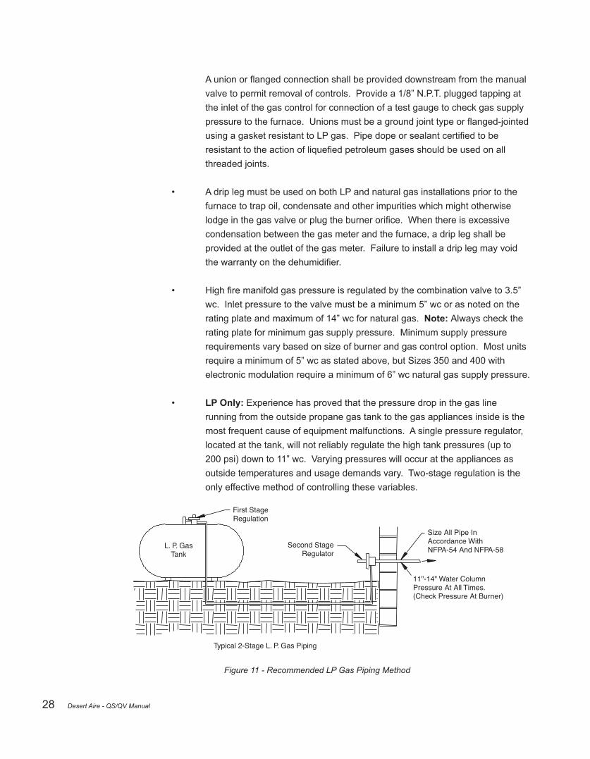
• LP Only: Experience has proved that the pressure drop in the gas line running from the outside propane gas tank to the gas appliances inside is the most frequent cause of equipment malfunctions. A single pressure regulator, located at the tank, will not reliably regulate the high tank pressures (up to 200 psi) down to 11” wc. Varying pressures will occur at the appliances as outside temperatures and usage demands vary. Two-stage regulation is the only effective method of controlling these variables.
First StageRegulation
L. P. GasTank
Second StageRegulator
Typical 2-Stage L. P. Gas Piping
Size All Pipe InAccordance WithNFPA-54 And NFPA-58
11"-14" Water ColumnPressure At All Times.(Check Pressure At Burner)
Figure 11 - Recommended LP Gas Piping Method
Desert Aire - QS/QV Manual

29
• LP Only: Use the following line size chart to size the gas piping or tubing between the LP tank and the second-stage regulator:
Section 1 Section 2
Total input load (Btu/h)
on line
125,000
250,000
375,000
500,000
lf the length of line between regulators (tank to building) is this long.
Use
this
siz
e tu
bing
to k
eep
pres
sure
dro
p be
low
2 lb
s.
for m
axim
um fl
ow s
how
n.
Use
this
siz
e tu
bing
or p
ipe
to k
eep
pre
ssur
e dr
op b
elow
1/2
” w
ater
co
lum
n fo
r max
imum
flow
sho
wn.
Total input load (Btu/h)
on line
75,000
125,000
187,500
250,000
375,000
500,000
lf the length of line between second-stage regulator and furnace is this long.
25’ 100’
1/2” O. D.Copper
50’ 75’ 10’
5/8” O. D.Copper
20’ 30’ 40’ 50’
3/4” BlackPipe
1” Black Pipe
1” Black Pipe
3/4” Black Pipe
3/4” Black Pipe
3/4” Black Pipe
5/8” O. D. Copper3/8” O. D. Copper
3/8” O. D. Copper
1/2” O. D. Copper
1/2” O. D. Copper
Figure 12- LP Gas Pipe Sizing Information
• LP Only: Seamless copper tubing may only be used with gases that are not corrosive to it. See the note below to check with your LP gas supplier before using copper. Seamless copper tubing must comply with standard type K or L for seamless copper water tube, ASTM B 88; or seamless copper tube for air conditioningfieldservice,ASTMB280.
• LP Only:Copperandbrasstubingandfittings(excepttinlined)shallnotbe used if the gas contains more than a trace (0.3 grains per cubic ft.) of hydrogensulfidegas.Checkwithyourgassupplier.
• LP Only:
- TotalAire™ units-maximumsupplypressureforliquefiedpetroleum (LP) gas is 14” wc and minimum supply for purpose of input adjustment is 11” wc.
- Aura™ units–maximumsupplypressureforliquefiedpetroleum(LP) gas is 13.5” wc and minimum supply for purpose of input adjustment is 11” wc.
Beforeattemptingtomeasureoradjusthighfiremanifoldgaspressure,theinlet(supply) pressuremustbewithinthespecifiedrangeforthegasbeingbothusedwhentheheaterisin operation and on standby. Incorrect inlet pressure could cause excessive manifold gas
Desert Aire - QS/QV Manual

30
pressure immediately or at some future time. With the manual valve, on the combination valve,positionedtopreventflowtothemainburners,connectamanometertothe1/8”pipe outlet pressure tap on the valve. Open the valve and operate the heater to measure the manifold gas pressure. Note:Amanometer(fluidfilledgauge)isrecommendedratherthan aspringtypegaugeduetothedifficultyofmaintainingcalibrationofaspringtypegauge. Normally adjustments should not be necessary to the factory present regulator. If adjustment is necessary, set pressures to above settings by turning regulator screw IN (clockwise) to increase pressure. Turn regulator screw OUT (counter clockwise) to decrease pressure. Consultthevalvemanufacturer’sliteratureprovidedwiththeheaterformoredetailed information.
2.10.3 Gas Heater Location The following items must be considered when choosing the size and location of the furnace.Notethatdehumidifiersdesignedforoutdoorusearealreadyequippedwith combustion air intakes and venting means. Field-installed venting is only required on indoordehumidifiers.
• All local codes and/or regulations take precedence over the instructions in this manual and should be followed accordingly. In the absence of local codes, installation must conform to these instructions, regulations of the National Fire Protection Association, provisions of National Electrical Code (ANSI/NFPA70 latest edition), and the National Fuel Gas Code (ANSI Z223.1 latest edition).
• Indoor units only:Thedehumidifiershouldbelocatedasnearthevent terminal as practical to minimize the numbers of elbows and the length of any horizontalrunofconnectingfluepipewhichmayberequired.
• Definitionsof“combustiblematerial”and“non-combustiblematerial”asissued by ANSI Z223.1 are as follows:
- Combustible Material: Material made of or surfaced with wood, compressedpaper,plantfibers,plasticsorothermaterialthatwill igniteandburnwhetherflameproofornotorwhetherplasteredornot.
- Non-Combustible Material: Material which will not ignite and burn; such materials consisting entirely of steel, iron, brick, concrete, slate, glass, plaster, or combination thereof.
• Indoor units only: Thedehumidifiermustbelocatedonalevel,drysurfacein an area which is free from and protected from excessive drafts or wind. It must be installed so that the electrical components are protected from water. Iftheareabecomeswetordampattimes,thedehumidifiershouldberaised abovethefloorusingconcreteblocksorsteeldunnage.
Desert Aire - QS/QV Manual

31
• Measures should be taken to prevent the entry of corrosive chemicals or vapors to the combustion and ventilation air supply. Such chemicals include butarenotlimitedtochlorinatedand/orfluorinatedhydrocarbonssuchas foundinrefrigerants,aerosolpropellants,drycleaningfluids,degreasers,and removers. Other harmful compounds may come from bleaches, air fresheners or mastics. Vapors from such products can form acid compounds whenburnedinagasflame.Shouldacidcompoundsforminyourfurnace;it may reduce the life of the furnace. Please follow these guidelines for providing outside air directly to the appliance to avoid this problem.
• Thereturnairductofthedehumidifiermustbesealedairtighttoprevent starvation of the combustion air, especially if the burner is located in a con finedarea.
All separated combustion, power vented units MUST BE equipped with both combustion air and exhaust piping to the outdoors. The unique concentric adapter assembly designed for use with this heater allows for both combustion air and exhaust piping with only one horizontal or vertical penetration hole in the building.
The systems indicated in this manual are the only venting/combustion air systems approved for these separated combustion units. Do not use this concentric adapter box with any other product.
Do not use an existing venting system. This heater REQUIRES installation of the combustion air/vent system supplied with the unit.
Installationshouldbedonebyaqualifiedagencyinaccordancewiththese instructions.Thequalifiedserviceagencyinstallingthisseparatedcombustionsystem is responsible for the installation.
Hazards of Chlorine – The presence of chlorine vapors in the combustion air of gas-firedheatingequipmentpresentsapotentialcorrosivehazard.Chlorine,found usuallyintheformofFreonordegreaservapors,whenexposedtoflame,will precipitate from the compound, and go into solution with any condensation that is present in the heat exchanger or associated parts. The result is hydrochloric acid which readily attacks all metal including 300 grade stainless steel. Care should be taken to separate these vapors from the combustion process. This may be done by wise location of unit vent terminal and combustion air inlet with regard to exhausters or prevailing wind directions. Remember, chlorine is heavier than air. This fact should be kept in mind when determining installation location of these heaters and building exhaust systems.
Desert Aire - QS/QV Manual

32
Desert Aire units are not designed or approved for use in atmospheres containingflammable vapors or atmospheres highly laden with chlorinated vapors.
The following requirements must be followed when connecting this furnace to a vent system:
• The connection of this burner to the vent system shall be in accordance with thelocalbuildingcodes,theventmanufacturer’sinstructionsandPart7, venting of equipment, of the National Fuel Gas Code, ANSI Z223.1 (latest edition).
• You must tightly seat all joints of the vent. The inside of the vent should be free of all obstructions.
• Allventsandventconnectionsmustfittightlytoavoidairleaks.
• All vent connectors connecting the furnace to the vent must be rigidly supported with hangers and straps, in order to prevent sagging and movement after installation. The vent connector must be supported every four feet for the design and weight of the material used, to maintain clearances, and to prevent physical damage. The vent pipe must slope upward 1/4” minimum for each foot of horizontal run away from the furnace.
• Vent connectors used in connecting the furnace to the vent cannot be channeledthroughfloors,ceilings,andwallswithouttheproperprotective construction. This construction must be in accordance with the requirements of the National Fuel Gas Code (ANSI Z223.1 latest edition).
• The venting system must be installed to avoid possible contact with concealed plumbing or electrical wiring.
The addition to following the requirements outlined by local codes, follow the guidelines below when locating the vent terminal to help ensure trouble-free operation of your horizontally vented burner:
• Avoid locating the vent terminal on a wall facing the prevailing winds or wide-open areas. When this is not practical, choose locations that protect the vent from strong wind, such as behind a fence or a hedge. (Note: The vent terminalmustbelocatedsufficientlydistantfrombushes,shrubsand vegetationsoasnottohavetheflueproductsrestrictedorblockedbysuch vegetation.).
Desert Aire - QS/QV Manual

33
• In areas with considerable snowfall, locate the vent terminal higher than the recommended minimum 12 inches above the ground as protection from blockage by snow accumulation or drifting.
• Locating the vent terminal as close as possible to the outside corner of a building rather than centered on an open wall will also minimize the effect of direct winds. Avoid alcoves and similar areas that may increase wind loading of the vent termination.
Follow these steps outlined in the National Fuel Gas Code, NFPA 54/ANSI Z223.1 – latest edition to resize the vent system to approach the minimum size using the appropriate tables in the Appendix of that code. The National Fuel Gas Code may be obtained by writing the American Gas Association Laboratories, 8501 East Pleasant Valley Road, Cleveland, OH 44131 or the National Fire Protection Association, Batterymarch Park, Quincy, PA 02269.
Refer to the documents located in the heater module for more detail instructions on installationonyourspecificterminalunit.
2.11 Electric Heater (Optional) For Aura™ Products
In order to keep the controls of the electrical heater cool, there are two openings in the panel adjacent to the heater. The hoods for rain protection of these openings are shipped with the unit, and the mounting hardware is already in place. Mount the hoods over the heater cooling openings using this hardware.
2.12 Auxiliary Heat Coil Piping (Optional)
TheDesertAiredehumidifiermaybeequippedwithanoptionalhotwaterorsteamairheating coil. This coil, when properly sized, will provide space heating during the winter months. Use proper practice when designing and installing the coil piping to prevent poor coil performance, shortened service life, or damage to the coil.
• The supply connections must not be supported by the coil headers. •Thecontrolvalveshouldbesizedaccordingtothepressureandflowraterequirementsnot by the coil connection size. • On steam systems, use strainer, dirt pockets, and isolation valves to prevent clogging the control valve and to simplify service. • Install swing joints in the connection piping to prevent damage to the coil header from thermal expansion. • Use a backup wrench on the pipe stubs when attaching connections to prevent damage to the header.
Desert Aire - QS/QV Manual

34
2.13 Smoke Alarm Interlock
DesertAireIAQdehumidifiersareequippedwithasetofterminalblocksforinterlockingwithasmokealarm (alarm provided and installed by others). The smoke alarm contacts must be rated for at least 15 amps at 24 VAC. The contacts must break when smoke is present. This will shut off the blower(s) and compressors. Seethedehumidificationwiringdiagramforconnectiondetails.
2.14 Cover Plates (if applicable)
Cover plates for the lifting bar locations are shipped with outdoor TotalAire™ units. The plates can be used toblockaccessundertheunitwheninstalledonacurb.Coverplatesshouldbeinstalledafterthefinal positioning of the unit.
Insert zip screws atthesefour locations
Figure 13 -Cover Plate Installation
1. The Packet should contain items as shown in the Table below, for various Plate Sub-Assemblies. The Plate Sub-Assembly to be used will depend upon size of the Unit. Please check the packet for correctness of items and quantities.
Sub-AssemblyTA-RAIL PLT 4-2TA-RAIL PLT 4-4TA-RAIL PLT 4-6TA-RAIL PLT 6-2TA-RAIL PLT 6-4TA-RAIL PLT 6-6TA-RAIL PLT 6-8
Cover Plates Quantity2462468
Zip Screws Quantity8
16248
162432
Figure 14 -Sub-Assembly Quantities
2. One cover plate is to be used for each channel stiffener. The purpose of installing this plate is to cover the two rigging holes in stiffener to minimize leakage of air through them. 3. Align the cover plate with the channel stiffener as shown in Figure 13. Place the cover plate on the channel stiffener, ensuring that the holes in the cover plate coincide with the four blank holes in the stiffener.
Desert Aire - QS/QV Manual

35
4. Drive four 1/4 x 1 1/4 zip screws through these four holes into the channel behind the stiffenerasillustratedinthefigure.Tightenthescrewsuntiltheplateisfirmlyheld against the stiffener.
5. Complete the installation of remaining cover plates following the above procedure.
2.15 Roof Curb w/ Wood Nailer (if applicable)
Certain options for curbs shipped with the Aura™ units include a treated wood nailer and flashinginstalledonthesideofthecurb.Thisallowsfordrainingofthepaninstalledunderthe condensersection.Thenailerandflashingshouldbecarefullyinspectedonfinalinstallation oftheroofmaterial.Anyseparationoftheflashingfromthecurbduetotransportationand liftingwillcausewatertopenetratebehindtheflashingandpasttheroofmaterials.Re-caulk as required to close any gaps that may have occurred.
Figure 15 - Wood Nailer
Desert Aire - QS/QV Manual

36
NOMINAL 1" x 4"PRESSURE TREATEDSOFTWOOD NAILER
14 GAUGEGALVANIZEDSTEEL WALL
12 x 1" HARDENEDHOT DIPPED GALVANIZEDSTEEL SCREW SHANK NAILSAT 12" O.C. & COUNTERSUNK
12-14 x 1/1/4"
CAULK
1-1/2"
1-3/4"
1"
3/4" Mastic
18 GaugeGalvanizedFlashing
Figure 16 -Wood Nailer Detailed
2.16 Wheel Module Installation (Optional for Aura™ Products) As soon as the main unit is acceptably located, locate the wheel module such that the duct connection is aligned to the intake of the main unit as closely as possible. If the system is on a curb, place the module such that it is supported on the curb while still aligning the duct connection as accurately as possible.
Use come-along winches to draw the two components together. As soon as they are aligned, screw together thematingflangesfromtheinsideusingtheholesonthemainunitforguidance.Allholesmustbepopulated. Caulktheseambetweenthetwomatingflangesonthetopandsides.Installthetopcoverpieceandcaulkit to the duct connection.
Cables for power and communication to the wheel are provided within the wheelmodule behind the door adjacenttotheconnection.Flexibleconduitisalsoprovided.Inserttheflexibleconduitintotheflexibleconduit fittingsontheunitandthemodule.Tightenthefittings.Threadthepowercablethroughthecableglandonthe inside rear of the module and into the main unit. Continue threading the cable through each gland up to the electrical cabinet for the unit. When the cable is entirely within the electrical cabinet, verify the cable has not bunched in any location and there is only minimal slack to the cable. It is not necessary to pull the cable taught,justenoughtopreventexcessiveslackthatcouldbedisplacedbyairflow.Tightenallcableglandsthrough which the power cable passes. Land the wires in the open terminals of the power block per the wiring diagrams. Repeat the above process for the communication cable, landing the leads in the appropriate terminal block per the wiring diagram. Foroutdoorunits,anexhausthoodwillbeshippedinsidetheunittobefieldinstalled.Installthehoodusing thehardwareprovided.Alignthehoodbythefasteninglocationsonthesideofthehoodfirst,andthetoplast.
Desert Aire - QS/QV Manual

37
3 Start-Up Procedure
ReadthissectionthoroughlybeforeattemptingtocommissiontheDesertAiredehumidifier. A complete start-up will minimize operational problems and expensive callbacks. The start-up will be quicker and easier if there is a heat and humidity load present in the space. Energize any external auxiliary heaters before start-up so that the air is at the design temperature.
3.1 Preliminary Inspection
Verify that all contractors have completed their work. Find the Desert Aire Start-Up Report for QS/QVModels,whichisneartheendofthismanual.Youmustfilloutthestart-upreportto validatethedehumidifierwarranty.Checkthefollowingitems:
• Before starting unit, remove wooden shipping blocks found beneath compressor(s).
• Before starting unit, remove shipping restraining brackets on supply and/or exhaust blower equipped with a spring isolation base, if applicable.
• Make sure that the unit is level and securely mounted so that it cannot shift or transmit vibration to the building.
• Verifythattheincomingpowersupplymatchestheratingplateofthedehumidifier. The available power supply voltage must be within ±10% of the voltage printed on the rating plate. • Withthepowersupplydisconnectedandlocked,tightenallfieldandfactoryelectrical connections. This includes all connections in the compressor and motors. • Checkandadjustthebelttensionforproperdeflectionatthemid-pointoftheblower belt(s).
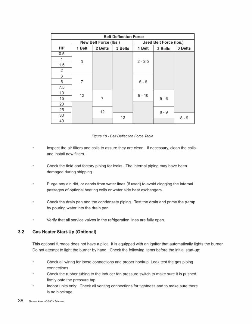
• Thedeflectionisbasedonthebeltlength.Thebeltlengthcanbefoundonthebelt itself.DeterminetheforceusingtheBeltDeflectionForcetablebelow.
Belt Length25” to 50”51” to 70”71” to 110”
Deflection0.25”0.375”0.625”
Specified Belt Deflection
Figure 17 - Specified Belt Deflection Table
Desert Aire - QS/QV Manual
38
HP0.51
1.5235
7.5101520253040
1 Belt
3
7
12
Belt Deflection Force
2 Belts
7
12
3 Belts
12
2 Belts
5 - 6
8 - 9
New Belt Force (lbs.) Used Belt Force (lbs.)
1 Belt
2 - 2.5
5 - 6
9 - 10
3 Belts
8 - 9
Figure 18 - Belt Deflection Force Table
• Inspecttheairfiltersandcoilstoassuretheyareclean.Ifnecessary,cleanthecoils andinstallnewfilters.
• Checkthefieldandfactorypipingforleaks.Theinternalpipingmayhavebeen damaged during shipping.
• Purge any air, dirt, or debris from water lines (if used) to avoid clogging the internal passages of optional heating coils or water side heat exchangers. • Check the drain pan and the condensate piping. Test the drain and prime the p-trap by pouring water into the drain pan.
• Verify that all service valves in the refrigeration lines are fully open.
3.2 Gas Heater Start-Up (Optional)
This optional furnace does not have a pilot. It is equipped with an igniter that automatically lights the burner. Do not attempt to light the burner by hand. Check the following items before the initial start-up:
• Check all wiring for loose connections and proper hookup. Leak test the gas piping connections. • Check the rubber tubing to the inducer fan pressure switch to make sure it is pushed firmlyontothepressuretap. • Indoor units only: Check all venting connections for tightness and to make sure there is no blockage.
Desert Aire - QS/QV Manual
39
It may be necessary to purge the air out of the gas line for initial start-up of the furnace after installation.Thisshouldbedonebyaqualifiedheatingcontractor.Ifexcessivegasescapes when purging the gas supply at the union, allow the area to ventilate for at least 15 minutes before attempting to start the furnace. LP gas is especially dangerous because it is heavier thanairandcanaccumulatetodangerousconcentrationsatfloorlevel.Heatexchangeroil willburnoffoninitialfiringcreatinganunpleasantodor.Topreventthisodorfromoccurring more than once, open doors and windows and run the blower for at least 30 minutes or until odor disappears.
Theorificefortheburnerswassizedforeithernaturalgas(havingaheatingvalveof1025 BTUpercubicfootandaspecificgravityof0.60)orforliquefiedpropanegas(withaheating valueof2500BTUpercubicfootandaspecificgravityof1.53).Seetheratingplateofyour dehumidifiertodeterminewhichtypeoffueltheheaterisconfiguredfor.
To verify the actual input of your natural gas burner, proceed as follows:
• Call your gas supplier and ask for the BTU content (heating value) of one cubic foot of the gas supplied to the installation area. An alternate approach is to assume a value of 1025 BTU/ft3, which is the national average.
• With all other gas appliances turned off, operate the burner for at least ten minutes. After the equipment has warmed up, use a stop watch to clock the time required for the small dial on the gas meter to make one full revolution. A label on the meter will statehowmanycubicfeethaveflowedperrevolution(usuallyone,twoorfive).
Input BTU/hour = (BTU/ft3 x ft3 x 3600 seconds) / (seconds / revolution)
EXAMPLE: (1025 BTU/ft3 x 2 ft3 x 3600) / 74.8 seconds = 98,663 BTU Input
Check for the input of the burner, the type of gas, and the required manifold pressure on the ratingplatelocatedontheexteriorofthedehumidifier.
Make sure that the gas supply pressure to the furnace falls within the maximum range of 6” to 14” wc pressure for natural gas and 11.0” to 14.0” wc for LP gas. The pressure to the furnace must be checked while the furnace burner and any other gas appliances on the same supply system are operating.
Theburnersareequippedwithfixedorificessizedforthemanifoldpressureshownonthe rating plate. The input can only be increased or decreased by adjusting the manifold pressure. Remove the 1/8” threaded pipe plug located on the top right side of the gas valve.
Use a U tube manometer or a pressure gauge to measure the pressure. To adjust the pressure, remove the screw from the regulator on the outlet side of the gas valve. Turn the
Desert Aire - QS/QV Manual

40
adjustment screw counterclockwise to decrease the pressure or clockwise to increase the pressure. ADJUSTMENTS TO THE LISTED PRESSURE MUST NOT EXCEED 0.3” wc. A 0.3” wc adjustment will increase or decrease the input approximately 0.4%. Replace the screw cap when the adjustment is complete.
Shut off the gas supply to the furnace. Remove the pressure gauge and re-install the pipe plug using a threaded compound resistant to the action of LP gases.
Iftheratedinputcannotbeobtainedwiththepresentorificeatthecorrectpressure,yourlocal gassupplierwillassistinsizingtheproperorifice.TheDesertAireServiceDepartmentwill gladlyhelpyousizetheorificeifyouprovidethemwiththeheatingvalueinBTUpercubicfoot andthespecificgravityofthegas.
3.2.1 Burner Adjustment TotalAire™ and Aura™ units only: Burner air shutters are not normally required on natural gas furnaces. Air shutters are required on propane gas units and may require adjustment. Before making any adjustments to the air shutters, allow the heatertooperateforaboutfifteenminuteswiththeairshuttersopen.Theslotted screw on the end manifold bracket moves the air shutters and adjusts all burners simultaneously. Turning the screw clockwise opens the shutters; counterclockwise closes the shutters. After the furnace has been in operation for 15 minutes, close the airshuttersobservingtheflameforyellow-tipping.Opentheshuttersuntiltheyellow disappears.Alimitedamountofyellowtippingispermissibleforliquefiedpetroleum gases. Natural gas should not display any yellow-tipping. When making the adjustment, close the air shutters no more than is necessary to eliminate the problem condition.
After 15 – 20 minutes of continuous operation, the air temperature rise across the burner must be no higher than 85°F. If the outlet or supply duct temperature is too high,youmustbalancethesupplyairflow.
3.3 Airflow Balancing
Toensurecodecomplianceandlongequipmentservicelife,properairflowmustbeverifiedby aqualifiedairbalancer.Shutoffthecompressortopreventtherefrigerationfromrunningwhile you balance the air. If the unit is equipped with a Supply Fan Variable Frequency Drive (VFD) thentheblowerspeedwillbemodifiedattheVFD.
Unitairflowrateisspecifiedatthetimeoforder.Theflowrateeachunithasbeendesignedfor isindicatedonalabelneartheairbalanceports.Apressuredifferentialacrossafixedsetof componentsthatcorrespondswiththeflowrateisshownonthelabelaswell.Thisisa convenientmethodofsettingandcheckingtheflow.Alternatively,externaltestandbalance maybecompletedwithvelometer,anemometer,flowhood,orothertestingdevices.Inall casestheflowrateshouldbesetaccordingtothelabeltoensureappropriateoperationand system reliability.
Desert Aire - QS/QV Manual

41
3.3.1 Blower Adjustment Procedure
Disconnect Power to the Unit before you adjust the Blower.
3.3.1.1 Units with an EC Blower Aura™ units use electronically commutated (EC) blowers. The speed of these blowersiscontrolledbya-10Vsignalfromthecontroller.Airflowmonitoring is achieved within the unit based on differential pressure measured by a transducer.Airflowrateismaintainedbyacontrolloopwhichvariesthesignal to the blower in order to achieve the differential pressure associated with the requiredairflow.
Oncetheairflowisadjusted,reviewthemotorcurrentdraw.Ifthecurrentdraw is in excess of the current rating listed on the unit nameplate or the drive is unabletoachievetheairflowatthemaximumsetting,theunitmaybe experiencing external static pressure in excess of the design condition. Check the external static of the ducting to/from the unit and reduce it until it is equal to or less than the design condition indicated on the rating plate. If issues persist, consult the Desert Aire Service Department 262-946-7400. Prior to any calls to the Desert Aire Service Department please have the unit serial number and model number available.
3.3.1.2 Unit without a VFD Change the blower speed by adjusting the motor pulley. To adjust the variable pitchpulley,firstloosenthesetscrew.Toslowdowntheblower,turntheouter pulley face counterclockwise (to decrease its pitch diameter). To speed up the blower, turn the outer pulley face clockwise (to increase its pitch diameter).
After every adjustment be sure to:
• Tightenthesetscrewagainsttheflatspotonthepulleyhubsoyou don’tdamageanythreads.
• Adjust the belt tension if needed.
• Check to assure that the blower motor current draw does not exceed the rating printed on the rating plate.
Iftheblowermotorcurrentdrawexceedsitsratingbutyourairflowisstilltoo low, the static pressure losses in the ductwork and grilles may be higher than
Desert Aire - QS/QV Manual

42
the unit was designed for. If this happens, consult the Desert Aire Service Department 262-946-7400. Prior to any calls to the Desert Aire Service Department please have the unit serial number and model number.
3.3.1.3 Unit with a VFD The usage of the VFD controlled blowers allows for a simple way to achieve the correct speed required for proper air balancing. Starting and stopping of the blowers shall be controlled by the CM3500 control system outputs. Therefore, the VFD needs to run in the automatic mode.
CAUTION: When modifying the VFD settings, the minimum speed should notbesettoallowtheairflowtofallbelowtheairflowrequiredfortheunitas shown on the unit nameplate. The maximum frequency setting of the blower motor assembly is 75 Hz.
SincetheVFDisbeingusedtosetonespecificspeed,theanalogreference isnotused.Thisshouldbeconfirmedbyexaminingthewiringschematic diagram. If no analog reference signal is connected to the VFD, the drive will always run at the minimum speed setting when it is commanded on. Determination of this speed needs to be done during the test and balance phase of the commissioning by increasing the minimum speed setting, as a frequency, until the proper CFM is achieved. This frequency should be recorded near the VFD for future reference.
Oncetheairflowisadjusted,reviewthemotorcurrentdraw.Ifthecurrentdraw is in excess of the current rating listed on the unit nameplate or the drive is unabletoachievetheairflowatthemaximum75Hzsetting,consultthe Desert Aire Service Department 262-946-7400. Prior to any calls to the Desert Aire Service Department please have the unit serial number and model number.
3.3.2 Airflow Balancing for Dedicated Outside Air Systems (DOAS) Dehumidifiersdesignedfordedicatedoutsideairoperationwithoutunoccupied recirculationmodehaveasingleflowpathforsupplyair.Theunitmayhaveanenergy recovery wheel and an exhaust airstream, but these paths do not mix in a DOAS unit. A damper is installed on the intake of the units ordered for outdoor installation; provisionsforfieldinstalleddamperareprovidedonunitstobeinstalledindoors. Damper actuator is two-position. Damper should be in the fully closed position during unoccupied mode and fully open in occupied mode. Before starting the balancing process check the damper to ensure it has fully indexed to the open position, and check that the ductwork is clear of any obvious restrictions.
Oncetheoutsideairdamperisfullyopen,verifythecorrectairflow.Iftoolittleairflow there is likely too much external static resistance. Evaluate ducts for high restriction or
Desert Aire - QS/QV Manual

43
adjust the blower speed as required per blower adjustment procedure.
3.3.2.1 Aura™ and TotalAire™ Units ThetotalairflowofaTotalAire™orAura™systemcanbecheckedby measuring the static pressure drop across one or more of the following componentsdependingontheconfiguration:thereheatcondenser,the evaporatorcoil,ortheenthalpywheel.Thedehumidifierfeaturesan adjustableblowersheavetosimplifyairbalancing.Tomeasureairflowof Aura™ units, measure the pressure drop across both the reheat condenser and dry evaporator. Aura™ units have convenient ports located in the electrical system compartment.
Figure 19- QS side view showing location of Air Balance Ports
Figure 20- Aura™ side view showing location of Air Balance Ports
Desert Aire - QS/QV Manual

44
Procedure:
1. Checktheconditionoftheairfilterstoassurethattheyareclean.
2. Check for any obvious restrictions in the ductwork.
3. Start the supply air blower.
4. Drive the outdoor air damper open, start the supply air blower, and energize thefield-installedexhaustairblowerbyturningonthe“occupied”switch. Consult wiring diagram for location of occupied binary input jumper or use the operating controller occupied scheduling feature.
5. For TotalAire™ Units without Enthalpy Wheel: Use a magnehelic or inclined manometer to measure the air pressure drop across the reheat condenser (ports#1and#2).Comparethisvaluetothevalueprintedontheairflowlabel onthesideofthedehumidifier.
For TotalAire™ Units with Enthalpy Wheel: Use a magnehelic or inclined manometer to measure the air pressure drop across the upper and lower sections of the enthalpy wheel. Compare these values to the values printed ontheairflowlabelonthesideofthedehumidifier.
For Aura™ units: Use a magnehelic or inclined manometer to measure the air pressure drop across the reheat and dry evaporator. Compare this value tothevalueprintedontheairflowlabelonthesideofthedehumidifier.
6. Changetheairflow,ifnecessary,byadjustingthemotorpulleyorany balancingdampersinthefield-installedductwork.
Always measure the current draw of the blower motor after you make any changes to theairflowquantity.IfthemotordrawsmorethanitsFLAratingbutthetotalairflowis still low, check the resistance of the ductwork. Verify that all grilles and dampers have been opened and that there are no sudden turns or restrictions in the ductwork. Refer to the mechanical equipment schedule or other indication from the building designerforrequiredflowrates.
3.3.2.2 Airflow Balancing for QV Dehumidifiers ThetotalairflowofaDesertAireVerticalAire™QVsystemcanbecheckedby measuring the static pressure drop across the reheat condenser and the dry evaporatorcoilformodels4-15tons.ForQVunits20-30tons,theairflowmay becheckedbymeasuringtheairflowacrossthereheatcoil.Thedehumidifier features an adjustable blower sheave to simplify air balancing.
Desert Aire - QS/QV Manual

45
Figure 21 - QV (4-15) ton showing location of Air Balance Ports
Procedure for QV 4 – 15 ton systems:
1. Checktheconditionoftheairfilterstoassurethattheyareclean.
2. Check for any obvious restrictions in the ductwork.
3. Start the supply air blower.
4. Drive the outdoor air damper open, start the supply air blower, and energize thefield-installedexhaustairblowerbyturningonthe“occupied”switch.
5. Use a magnehelic or inclined manometer to measure the air pressure drop across the evaporator and reheat coil (ports #1 and #2). Note: Ensure test is performed with refrigeration off and evaporator coil dry. See Figure 21. Comparethisvaluetothevalueprintedontheairflowlabelonthesideofthe dehumidifier.
6. Changetheairflow,ifnecessary,byadjustingthemotorpulleyorany balancingdampersinthefield-installedductwork.
Always measure the current draw of the blower motor after you make any changes to theairflowquantity.IfthemotordrawsmorethanitsFLAratingbutthetotalairflowis still low, check the resistance of the ductwork. Verify that all grilles and dampers have been opened and that there are no sudden turns or restrictions in the ductwork.
Desert Aire - QS/QV Manual

46
Discharge Duct
Figure 22 - QV (20-30) ton showing location of Air Balance Ports
Procedure for QV 20 – 30 ton systems:
1. Checktheconditionoftheairfilterstoassurethattheyareclean.
2. Check for any obvious restrictions in the ductwork.
3. Start the supply air blower.
4. Drive the outdoor air damper open, start the supply air blower, and energize thefield-installedexhaustairblowerbyturningonthe“occupied”switch.
5. Use a magnehelic or inclined manometer to measure the air pressure drop across the reheat coil. See Figure 22. Note: Port #1 is measuring the internal cabinet pressure downstream of the fan (high side) and port #2 is addedinthedischargeductinthefield,downstreamofthereheatcoil (low side).
Always measure the current draw of the blower motor after you make any changes to theairflowquantity.IfthemotordrawsmorethanitsFLAratingbutthetotalairflowis still low, check the resistance of the ductwork. Verify that all grilles and dampers have been opened and that there are no sudden turns or restrictions in the ductwork.
Desert Aire - QS/QV Manual

47
VerticalAire™dehumidifiersmaybeequippedwithadamperboxthatisolates the unit when in unoccupied mode. A damper actuator in the box positions the damperopenwhenoccupied.Airflowmustbebalancedinthismode.Ifthis option is equipped, operate the unit in occupied mode of operation and balance according to the DOAS procedure above.
3.3.2.2.1 Damper Box Equipped VerticalAire™ Systems VerticalAire™dehumidifiersmaybeequippedwithadamperbox that allows the unit to operate with recirculation air in the unoccupied mode. Damper actuators in the box position the dampers in the box to operate in full outdoor air mode or full recirculationmode.Airflowmustbebalancedinbothmodes.
3.3.3 Airflow Balancing for Dedicated Outdoor Air System (DOAS) with Unoccupied Recirculation For Aura™ Products Dehumidifiersdesignedfordedicatedoutdoorairoperationwithunoccupied recirculationmodehavetwopotentialflowpathsforsupplyair:fulloutdoorairorfull recirculation. The unit may have an energy recovery wheel and an exhaust airstream, but these paths do not mix in a DOAS unit. A damper is installed on the intake of the unitsorderedforoutdoorinstallation;provisionsforfieldinstalleddamperareprovided on units to be installed indoors. A recirculation damper is installed within the unit. Damper actuator control acts as binary. Outside air damper should be in the fully closed position during unoccupied mode and fully open in the occupied mode with the recirculation damper always in the opposite condition. Before starting the balancing process, check that the ductwork is clear of any obvious restrictions.
Begininoccupiedmode.Oncetheairflowdamperisfullyopenandtherecirculation damperisfullyclosed,verifythatthecontrollerindicatesthecorrectairflow.Iftoolittle airflowisdisplayed,buttheblowercontrolsignalisatmaximum,thereistoomuch external static resistance. Evaluate ducts for high restriction. Repeat the process for unoccupied mode, verifying that the outside air damper is fully closed and the recirculation damper is fully open. Allow the blower to reach steady state before verifyingthatthecontrollerindicatesthecorrectairflow.
For Aura™ units with an external enthalpy wheel, in occupied mode, use a magnehelic or inclined manometer to measure the air pressure drop of the exhaust blower. Increase the controller signal up or down until the exhaust air pressure drop matches the pressure drop indicated on the wheel module label. DOAS units do not have automatic control of the exhaust blowers. Verify that, in unoccupied mode, the exhaust blower shuts down.
For TotalAire™ and VerticalAire™ Products Dehumidifiersdesignedfordedicatedoutdoorairoperationwithunoccupied
Desert Aire - QS/QV Manual

48
recirculationmodehavetwopotentialflowpathsforsupplyair:fulloutdoorairorfull recirculation. The unit may have an energy recovery wheel and an exhaust airstream, but these paths do not mix in a DOAS unit. A damper is installed on the intake of the unitsorderedforoutdoorinstallation;provisionsforfieldinstalleddamperareprovided on units to be installed indoors. A recirculation damper is installed within the unit. Damper actuator control acts as binary. Outside air damper should be in the fully closed position during unoccupied mode and fully open in the occupied mode with the recirculation damper always in the opposite condition. Before starting the balancing process, check that the ductwork is clear of any obvious restrictions. Begin in occupied mode.Oncetheairflowdamperisfullyopenandtherecirculationdamperisfully closed,verifythattheairflowiscorrect.Iftoolittleairflow,thereistoomuchexternal static resistance. Evaluate ducts for high restriction and adjust the blower speed as required per blower adjustment procedure. Repeat the process for unoccupied mode, verifying that the outside air damper is fully closed and the recirculation damper is fully open.Verifythattheairflowiscorrect.Iftoolittleairflow,thereistoomuchexternal static resistance. Evaluate ducts for high restriction and adjust the blower speed as required per blower adjustment procedure.
Note, if total static pressure does not match in both modes of operation, and one mode hashigherairflow,itmaybenecessarytoinduceadditionalstaticpressureinone modetoreducetheairflowforthatmode.Toaccomplishthisamaximumdamper opening percentage may be set within the controller.
3.3.4 Airflow Balancing for High Outdoor Air Systems (HOAS) For Aura™ Products Dehumidifiersdesignedforhighoutdoorairoperationmixoutdoorairandreturnair before treating it. A damper is installed on the intake of the units ordered for outdoor installation;provisionsforfieldinstalleddamperareprovidedonunitstobeinstalled indoors. A recirculation damper is installed within the unit. Damper actuator control is proportional for both dampers. Controls may be set to allow for a mixed air condition duringoccupiedmodeandfullrecirculationduringunoccupiedmode.Airflowmustbe balanced in both modes.
Notethatductairflowmeasurementequipmentwillberequiredtomeasuretheamount ofairflowineachmode.Beforestartingthebalancingprocess,checkthatthe ductwork is clear of any obvious restrictions.
Operate the unit in occupied mode of operation. Initially the controller will index the outside air damper fully open and the return air damper fully closed. Verify the blower ismaintainingdesignairflow;itshouldmaintainthedesignairflowthroughout balancing so long as damper position changes are done slowly.
Use the controller to adjust the recirculation damper to a more open position. Check
Desert Aire - QS/QV Manual

49
thereturnairductflowrateaftereveryadjustment,andcontinueadjustinguntilthe ratioofflowsiscorrect.Incaseswherethereturnairstaticpressureishigh,the recirculation damper may be fully open without the desired ratio being attained. In this case, keep the recirculation damper fully open and adjust the outside air damper to a moreclosedposition.Checkthereturnairductflowrateaftereveryadjustment,and continueadjustinguntiltheratioofflowsiscorrect.Verifytheblowerhasmaintained thesupplyairflow.
Switch to unoccupied mode and verify that the outside air damper closed completely, therecirculationdamperopenedcompletely,andthesupplyairflowismaintainedat steady state (this may take a few moments as the blower control loop stabilizes).
3.3.4.1 For Units with External Enthalpy Wheel (Aura™) In occupied mode, use a magnehelic or inclined manometer to measure the air pressure drop of the exhaust blower. Increase the controller signal up or down until the exhaust air pressure drop matches the pressure drop indicated on the nameplate. Then complete the balancing from section 3.3.4.
Check the pressure drop of the exhaust blower after balancing the dampers and adjust the exhaust blower signal as necessary. Verify the exhaust blower adjustment did not alter supply air operation. If the adjustment has altered supply air operation, repeat the supply air balancing and then the exhaust air adjustmentuntilallairstreamsarewithinspecifications.Verifythat,in unoccupied mode, the exhaust blower shuts down.
3.3.4.2 For Units with CO2 Control (Aura™) DehumidifiersdesignedforCO2controlcanhavemixedairflowcomposedof a range from 100% outside air to a minimum ratio of outside air dictated by the design. The outside air damper, recirculation damper, supply blower, and exhaust blower are all controlled by PID loops. To balance, set the CO2 set point to 200 ppm and verify the pressure drop across the supply side of the wheel is at a minimum indicated on the nameplate. Also, verify the supply blowerismaintainingthedesignairflow.
Adjust the CO2 set point to 2000 ppm and verify the outside air damper opens fully, the recirculation damper closes fully, and the supply blower still maintains thedesignairflow.
For TotalAire™ Products TotalAire™dehumidifiersmaybeequippedwitharecirculationdamperthatallowsfor mixing of outdoor air and return air. A separate damper and actuator are installed between the return air and outside air streams prior to the exhaust air entering the enthalpy wheel. Controls may be set to allow for a mixed air condition during occupancyand/orfullrecirculationairduringunoccupiedmode.Airflowmustbe balanced in both modes.
Desert Aire - QS/QV Manual
50
Notethatductairflowmeasurementequipmentwillberequiredtomeasuretheamount ofairflowineachmode.
3.3.4.3 Recirculation Mode (TotalAire™) Operate the unit in unoccupied mode of operation. Check to ensure that the outside air damper indexes to the fully closed position, the return air damper indexes to the fully open position, and the exhaust fan and enthalpy wheel turn off.Adjusttheblowerspeedsuchthattheairflowmeetsspecifications.
3.3.4.4 Mixed Air Mode (TotalAire™) Operate the unit in occupied mode of operation. Initially the unit will index the outdoor air damper fully open and the return air damper fully closed. Use the maximum open position setting within the controller on the recirculation damper to adjust the damper to a more open position in this mode. Check the returnairductflowrateuntiltheratioofflowsandthetotalflowiscorrect.Do not adjust the blower speed at this time. In cases where the return air static pressure is high, you may reach the full open position of the outside air damper before the desired ratio is obtained. Additionally,theairflowmaybesignificantlyhigherthanthespecificationin this mode when this is the case. If this occurs, use the controller to adjust the outdoor air damper maximum open position to limit the stroke of the actuator to a less open position during this mode. Adjust the return air damper to the close position and outdoor air damper to theopenpositionuntilthedesiredratioandtotalspecifiedairflowisachieved in occupied mode. Checkthepressuredropacrosstheenthalpywheelaccordingtotheairflow labelonthesideoftheunit.Changetheexhaustairflow,ifnecessary,by adjustingthemotorpulleyoranybalancingdampersinthefield-installed ductwork. Verify exhaust air adjustments did not alter supply air operation. If so, repeat aboveproceduresuntilallairstreamsarewithinspecifications.
3.3.4.5 For Units with Systems Equipped with Demand Controlled Ventilation Option (TotalAire™) TotalAire™ units equipped with the CO2ControloptionincludeVFD’sforthe supply and exhaust as well as a recirculation damper. Pressure differential across several components within the systems are measured. All of these devices are connected to the unit controller which takes the inputs from these pressure transducers and controls the fan speed accordingly.
Desert Aire - QS/QV Manual

51
The system is substantially self-balancing, but all modes must be checked at startup to ensure static pressures are within design criteria.
3.3.4.5.1 Unoccupied Mode with Recirculation (when specified) (TotalAire™) Units that are set for unoccupied mode of operation through the controlsshouldbebalancedinthismodefirst.Thismodeof operationisspecifiedatthetimeoforderandtheunitwillcome pre-set from the factory.
It is possible to add this mode of operation through the controller setupfunctionsinthefield.SeetheControllerIOManualfordetails. It should be noted that supply fan capability may be limited if the unit wasnotspecifiedforhisoperationattimeoforder.
Unoccupied mode may be programmed with Fan Cycling operation or Continuous in the controller. For balancing purposes, adjust the operation to Continuous.
Operate unit in unoccupied mode. Unit will close outdoor air damper, open the recirculation damper, disable the exhaust fan, and turn off thewheel.Confirmthattheexhaustairgravitydamperisshut. Supply air fan will modulate to maintain the programmed pressure differential over the reheat coil in the unit, maintaining the supply air flowrate.Checkthepressuredropaccordingtotheairflowlabelon the side of the unit. It is possible if the static pressures are higher thanspecifiedthattheflowratemaybelower.ChecktheVFD speed. Units will leave the factory with a maximum VFD speed of 65 Hz. This can be increased to 75 Hz maximum, subject to the current draw limitations of the fan motor. Review the settings in the VFD drive to increase the speed.
When the static pressure of the reheat coil is correct, check the motor current draw and compare to the FLA indicated on the unit rating plate.
3.3.4.5.2 Occupied Mode Minimum Outdoor Air (TotalAire™) Place the unit in occupied mode and create a low space CO2 reading (less than 200 PPM). An offset should be placed in the controller input to reduce the indoor sensor reading. If the reading is supplied by the BMS network, it is recommended that this reading be overridden at the BMS control.
Desert Aire - QS/QV Manual

52
The unit will modulate the exhaust and supply air variable speed drives, open the return air damper, and modulate the outdoor air damper. Check the pressure drop accordingtotheairflowlabelonthesideoftheunit.Itispossibleifthestatic pressuresarehigherthanspecifiedthattheflowratemaybelower.Checkthe VFD speed. Units will leave the factory with a maximum VFD speed of 65 Hz. This can be increased to 75 Hz maximum, subject to the current draw limitations of the fan motor. Review the settings in the VFD drive to increase the speed.
3.3.4.5.3 Occupied Mode Maximum Outdoor Air (TotalAire™) Place the unit in occupied mode and create a high space CO2 reading (greater than 2000 PPM). An offset should be placed in the controller input to reduce the indoor sensor reading. If the reading is supplied by the BMS network, it is recommended that this reading be overridden at the BMS control.
Checkthepressuredropaccordingtotheairflowlabelonthesideoftheunit. Itispossibleifthestaticpressuresarehigherthanspecifiedthattheflowrate may be lower. Check the VFD speed. Units will leave the factory with a maximum VFD speed of 65 Hz. This can be increased to 75 Hz maximum, subject to the current draw limitations of the fan motor. Review the settings in the VFD drive to increase the speed.
For VerticalAire™ Products VerticalAire™dehumidifiersmaybeequippedwithamixingboxthatallowstheunittooperatewith recirculation air in the unoccupied mode and/or mixing of airstreams during occupied mode. Two independentactuatorsallowpositioningofthedamperstotheappropriatesettings.Airflowmustbe balanced in all modes.
Ifoptionisequipped,firstoperatetheunitinoccupiedmodeandadjustthedamperpositionsviathe controllerdisplayindependentlyuntilthedesiredflowoftheoutdoorairandthereturnairisachieved. Outside air and return air duct will need to be measured independently by traverse or similar method if this includes mixing.
Operate the unit in unoccupied mode of operation. Typically the outdoor air damper will be set to 0% openposition.Adjusttherecirculationdamperpositiontomeettherequiredflowrateaccordingto static pressure differential per the balance label or independent test and balance measurements. The airflowshouldbeinthestaticpressuredifferentialrangeorwithin+/-10%ofthespecifiedairflow.
Shouldtheflowratebetoohighortoolow,notethestaticpressureinthemixingboxandcompareto thevaluemeasuredduringtheoccupiedmode.Ductstaticpressuresthataresignificantlydifferent willaffectairflowduringtheshiftingofmodes.Dampersorgrilleadjustmentswillbeneededtocreate similar static pressure drops in each mode. Evaluate the system and adjust the dampers accordingly.
Desert Aire - QS/QV Manual

53
3.4 Refrigeration Testing
Refrigeration based cooling systems are sometimes referred to as “sealed systems”. This is in reference to the refrigeration system being hermetically sealed, no refrigerant can leave the system and no contaminants are allowed inside. Factory equipment and procedure ensure a clean and tight refrigeration system where onlythespecifiedrefrigerantandoilareinthesystem.Thisisacriticalcomponenttothelongevityofthe system. Some Desert Aire systems are shipped in sections to allow for installation of some of the sections in a location muchdifferentthananother.Anexampleisaunitwitharemotecondenserreadycircuit.Thedehumidifier may be installed indoors near the conditioned space while the remote condenser used to reject waste heat is locatedoutdoors.Thepipingofthecondenseriscompletedinthefieldbeforetheunitiscommissioned.The designandprocessingofthefieldpipingisjustasimportantasthefactorypipinginensuringthelongevity of the system.
Selection of quality components, quality procedures, and full testing help to ensure the sealed system failures are minimized wherever possible. Nonetheless, the mechanical nature of many components creates some unforeseen wear and failure in certain instances. Some units may need service at a point in the life of the product that requires opening of the hermetic refrigeration system. Special care must be taken to ensure that the system is returned to service without contamination.
Whenever servicing Desert Aire equipment, observe the following:
• Use only equipment rated for the pressures of the refrigerant being serviced.
• Use only equipment dedicated to service the refrigerant in the system. Do not use equipment to service multiple refrigerant types.
• Purge all hoses and equipment of non-condensable gasses before connecting to the sealed system.
• Use only original equipment parts or factory approved equivalent for servicing. • Use required refrigerant system oil.
• Minimize the time the system is open to atmosphere while servicing. Cap all connections when there is no active service work on the system. This is particularly important with units that contain POE oils as moisture will be absorbed quickly and cannot be removed with a vacuum.
• Never open the system while under a vacuum. Should system require opening to repair a leak or otherservicewheninvacuum,fillwithdrynitrogentoatmosphericpressurebeforeopening.
• Have a Schrader core replacement tool available when servicing the refrigeration system. Although rare, defective or damaged Schrader valve cores can contribute to refrigerant loss.
• Chargesystemsonlybyweightafterservicing.Reviewtheratingplateandanyfieldchargelabels.
• Whenservicing,additionalliquidlinefilterdryersandsuctionfiltersmayberequired.ThisdoesnotDesert Aire - QS/QV Manual

54
apply to installation of remote condensers.
• Charge refrigerant blends, including R-410A and R-407C, with liquid only. Charging should be done into the high side of the system whenever possible. Refer to section 5.5 for additional procedures related to charging.
Notethatthesuperheatshouldbestableandwithin4degreesoffluctuation.Minimumvalue for superheat at compressor in all modes:
30.0 - 40.040.1 - 50.050.1 - 60.060.1 - 70.070.1 - 80.0
60.0 - 65.01213131414
Superheat Minimum Values Chart Temp °F
65.1 - 70.01314141515
70.1 - 75.01415151516
80.1 - 85.01516181819
75.1 - 80.01515161618
85.1 - 90.01618181920
Rel
ativ
e A
irH
umid
ity (%
RH
)
Relative AirTemperature °F
Figure 23 - Superheat Minimum Values Chart
3.4.1 Dehumidification / Cooling Mode
For Aura™ Products Inordertotesttheunitindehumidification/coolingmode,theairtemperatureenteringtheDX evaporator must be approximately 40°F or higher. If the condition entering the evaporator is lower, theevaporatormayaccumulatesignificantamountsoffrostand/orasuctionpressurealarmmay occur.
If a low outdoor air temperature condition prevents the unit from running long enough to take data, notethisonastartupreportandproceedtoheatpumpmode.DuringthefirstPreventative Maintenance visit that is recommended during spring and fall, the service contractor should complete theDehumidification/CoolingModesectionofthestartupreport.
To perform start-up checks on the compressor, the supply air dewpoint set point should be lower than the incoming dewpoint by at least 10°F. See the Controller IO Manual for instructions on setting the dewpoint set point. Note the original setting. Once the set point is adjusted, switch the unit to occupied mode.
The compressor is controlled by a PID loop that will modulate the speed of the compressor to the level necessary to achieve the desired dewpoint. It can take up to 15 minutes for the unit to reach steady state during which time, the noise of the compressor will vary in frequency and intensity. This is normal as the unit reaches steady state. During steady state operation, it is common for the compressor to ramp up for short periods (about 30 seconds) in order to ensure proper oil return. This will not substantially affect leaving air conditions and the unit will return to steady state within a few minutes.
Desert Aire - QS/QV Manual
55
Oilchargehasbeenconfirmedatthefactory.Intherarecasethatthecompressorisobservedto ramp up for oil return more than twice per hour, 20 oz additional POE oil should be added to the system.
While in steady state operation, record the data required for the start-up report. If the compressor is at maximum speed in steady state operation, it may be operating outside of design conditions. Check theairflowtoverifyexcessiveairflowisnotlimitingthedewpointcapabilitiesoftheunit.Ifthe dewpoint set point was adjusted, return it to its original value.
For TotalAire™ and VerticalAire™ Products Inordertotesttheunitindehumidification/coolingmode,theairtemperatureenteringtheDX evaporator must be approximately 50°F or higher. If the condition entering the unit is lower, the unit mayexperiencedifficultiesresultinginpooroperationorshutdownduetolowsuctionpressure.
If a low outdoor air temperature condition prevents the unit from running long enough to take data, notethisonastartupreportandproceedtoheatpumpmode.DuringthefirstPreventative Maintenance visit that is recommended during spring and fall, the service contractor should complete theDehumidification/CoolingModesectionofthestartupreport.
To perform start-up checks on the compressor, the supply air dewpoint set point should be lower than the incoming dewpoint by at least 10°F. See the Controller IO Manual for instructions on setting the dewpoint set point. Note the original setting. Once the set point is adjusted, switch the unit to occupied mode.
It can take up to 15 minutes for the unit to reach steady state. While in steady state operation, record the data required for the start-up report. If the dewpoint set point was adjusted, return it to its original value.
3.4.2 Heat Pump Mode For Aura™ Products In order to test the unit in heat pump mode, the air temperature entering the reheat condenser must be approximately 90°F or lower. If the condition entering the condenser is higher, the unit may run elevated head pressures and a high discharge pressure alarm may occur.
If a high outdoor air temperature condition prevents the unit from running long enough to take data, notethisonthestartupreport.DuringthefirstPreventativeMaintenancevisitthatisrecommended during spring and fall, the service contractor should complete the Heat Pump Mode section of the startup report.
To perform start-up checks on the compressor in heat pump mode, the supply air temperature set point should be higher than the incoming air temperature by at least 10°F. See the Controller IO Manual for instructions on setting the supply air temperature set point. Note the original setting. Once the set point is adjusted, switch the unit to occupied mode.
Desert Aire - QS/QV Manual

56
The compressor is controlled by a PID loop that will modulate the speed of the compressor to the level necessary to achieve the desired supply air temperature. It can take up to 15 minutes for the unit to reach steady state during which time, the noise of the compressor will vary in frequency and intensity. This is normal as the unit reaches steady state. During steady state operation, it is common for the compressor to ramp up for short periods (about 30 seconds) in order to ensure proper oil return. This will not substantially affect leaving air conditions and the unit will return to steady state within a few minutes.
Oilchargehasbeenconfirmedatthefactory.Intherarecasethatthecompressoris observed to ramp up for oil return more than twice per hour, 20 oz additional POE oil should be added to the system.
While in steady state operation, record the data required for the start-up report. If the compressor is at maximum speed in steady state operation, it may be operating outsideofdesignconditions.Checktheairflowtoverifyexcessiveairflowisnot limiting the heat pump capabilities of the unit. If the supply air temperature set point was adjusted, return it to its original value.
For TotalAire™ and VerticalAire™ Products In order to test the unit in heat pump mode, the air temperature entering the reheat condenser must be approximately 90°F or lower. If the condition entering the condenser is higher, the unit may run elevated head pressures and a high discharge pressure alarm may occur.
If a high outdoor air temperature condition prevents the unit from running long enough totakedata,notethisonthestartupreport.DuringthefirstPreventativeMaintenance visit that is recommended during spring and fall, the service contractor should complete the Heat Pump Mode section of the startup report.
To perform start-up checks on the compressor in heat pump mode, the supply air temperature set point should be higher than the incoming air temperature by at least 10°F and the incoming air humidity and the supply air dewpoint set point should be higher than the incoming dewpoint by at least 10°F. See the Controller IO Manual for instructions on setting the supply air and dew point temperature set points. Note the original setting. Once the set point is adjusted, switch the unit to occupied mode.
It can take up to 15 minutes for the unit to reach steady state. While in steady state operation, record the data required for the start-up report. If the supply air temperature set point was adjusted, return it to its original value.
Desert Aire - QS/QV Manual

57
3.5 General Testing
Afteryoubalancetheairflowandtesttherefrigerationcircuits,verifythattheotherequipment andaccessoriesconnectedtothedehumidifierworkproperly.Althoughthismaybedifficult, sincethedehumidifierisusuallyinterlockedwithavarietyofequipmentinstalledbydifferent contractors, you must not skip this step.
Each of these devices (which may include auxiliary air and water heaters, smoke alarms, circulating pumps, and a building management system) is vital in maintaining the performance of the unit. Many customer complaints are caused by improper interlocks between these devices. Make sure you check the following:
• Check the outdoor air and exhaust devices. The outdoor air and exhaust dampers mustopenwhentheyreceivean“occupied”signalfromthedehumidifier.Ifyouhave installed an exhaust blower, make sure that it is interlocked with the “occupied” signal or with an end switch on the outdoor air damper actuator.
• Check the condensate drain to make sure it has been trapped and primed with water. Verify that it drains freely, with no leaks. If the drain is outside or in an unconditioned space, make sure it has been heat traced. If you installed a condensate pump, make sure it operates properly.
• Check the operation of the remote condenser (on units equipped with this option). Make sure that the fans cycling switches, which are mounted on the condenser, are correctly piped and have been set according to the Desert Aire condenser wiring diagram. Verify that the fans are blowing air vertically upward when they run.
• Check the temperature and humidity readings displayed on the controller. If you think thevaluesareincorrect,checkthesensororitsfield-installedwiringfordamage.
• Check the operation of the auxiliary heaters by temporarily raising the air temperature set point on the Desert Aire controller. The duct heater(s) or heating valve should energize.
3.6 Routine Maintenance Schedule
3.6.1 Service Every Month
• Checktheairfiltersandreplacethemifnecessary.
• Checkthecoilsinthedehumidifierandtheremotecondenser.Use compressed air or a commercial coil cleaner if they are dirty or plugged.
• Verifythattheairflowaroundtheremotecondenserremainsunobstructed.
Desert Aire - QS/QV Manual
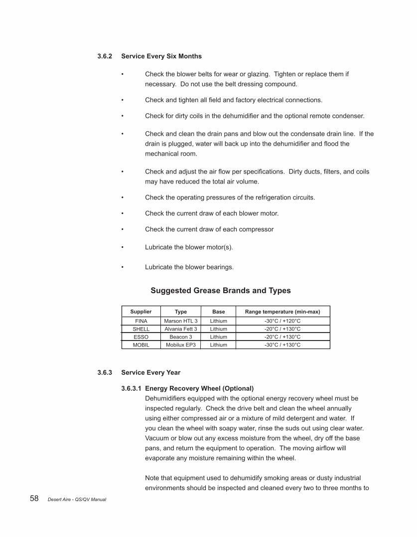
58
3.6.2 Service Every Six Months
• Check the blower belts for wear or glazing. Tighten or replace them if necessary. Do not use the belt dressing compound.
• Checkandtightenallfieldandfactoryelectricalconnections.
• Checkfordirtycoilsinthedehumidifierandtheoptionalremotecondenser.
• Check and clean the drain pans and blow out the condensate drain line. If the drainisplugged,waterwillbackupintothedehumidifierandfloodthe mechanical room.
• Checkandadjusttheairflowperspecifications.Dirtyducts,filters,andcoils may have reduced the total air volume.
• Check the operating pressures of the refrigeration circuits.
• Check the current draw of each blower motor.
• Check the current draw of each compressor
• Lubricate the blower motor(s).
• Lubricate the blower bearings.
Suggested Grease Brands and Types
FINASHELLESSOMOBIL
Type
Marson HTL 3Alvania Fett 3
Beacon 3Mobilux EP3
Supplier Base
LithiumLithiumLithiumLithium
Range temperature (min-max)
-30°C / +120°C-20°C / +130°C-20°C / +130°C-30°C / +130°C
3.6.3 Service Every Year
3.6.3.1 Energy Recovery Wheel (Optional) Dehumidifiersequippedwiththeoptionalenergyrecoverywheelmustbe inspected regularly. Check the drive belt and clean the wheel annually using either compressed air or a mixture of mild detergent and water. If you clean the wheel with soapy water, rinse the suds out using clear water. Vacuum or blow out any excess moisture from the wheel, dry off the base pans,andreturntheequipmenttooperation.Themovingairflowwill evaporate any moisture remaining within the wheel.
Note that equipment used to dehumidify smoking areas or dusty industrial environments should be inspected and cleaned every two to three months to
Desert Aire - QS/QV Manual

59
ensurehighoperatingefficiency.Seetheenthalpywheelinstructionmanual for more detailed information on maintaining and troubleshooting the wheel.
3.6.3.2 Gas Heater (Optional) Dehumidifiersequippedwithoptionalgasheatingshouldbeinspected annually before each heating season. Check the following items:
• Ensure that the vents and air intakes are clean and unobstructed.
• Clean the vent and condensate drain line if necessary. Repair any damaged sections of the vent.
• Inspect the pressure switch tubing connections. Verify that the inducer fan is free of corrosion, warp-age, deterioration, and carbon buildup. If necessary, clean the housing and the blower wheel with a damp cloth. Vacuum any lint or dust from the inducer motor assembly.
See the separate gas heater manual for detailed service information.
Note: Please have the following information available if you need to call the Desert Aire Service Department:
• Model Number
• Serial Number
• Room Temperature
• Relative Humidity
• Operating Refrigeration Pressures
• Water Temperature
• Compressor Amperage
• Blower Motor Amperage(s)
Desert Aire - QS/QV Manual

60 Desert Aire - QS/QV Manual

61
4 Troubleshooting
AlthoughDesertAiredehumidifiershavebeendesignedforreliableandtrouble-freeoperation, you may occasionally encounter a service-related problem. If you cannot immediately diagnoseandfixtheproblem,donotbeintimidatedbytheapparentcomplexityofthe dehumidifier.Yourcommonsenseandexperiencecanhelpyousolvethemajorityofthese problems.
These problems or complaints are frequently caused by improper interlocks between the dehumidifierandtheotherequipmentandaccessoriesatthejobsite.Youmayneedtoconsult with other contractors who have worked on different portions of this project.
The following list will help you diagnose some of the most obvious symptoms of a system which does not work properly.
4.1 The Blower Does Not Run
POSSIBLE CAUSES
“Occupied” switch is in the open position
Loss of main power
Damper is stuck or frozen, preventing the actuator end switch from closing
Blower overload has tripped
Faulty control wiring
REMEDY
Close “occupied” switch
Check for tripped circuit breaker or blown fuses
Free the damper or replace the actuator if it isdefective
Correct cause and reset overload
Check for loose or incorrect wires on systemand controller
Desert Aire - QS/QV Manual

62
4.2 The Compressor(s) Do Not Run Note: When there is a demand for outdoor air (the “occupied” switch is on) and the outdoor air doesnotneedmechanicaldehumidification,thecompressorandtherefrigerationcircuitsof thedehumidifierwillbelocked-out.
POSSIBLE CAUSES
Loss of main power
Blower overload has tripped
Faulty wiring
Compressor overload has tripped
Compressor failure may have occurred IF:
• Compressor draws locked rotor amps
• Compressor starts but does not pump
• Motor windings have shorted
Compressor delay time
REMEDY
Check for tripped circuit breaker or blown fuses
Correct cause of reset overload
Check for loose or faulty wiring on system anddehumidifier
Correct cause and reset overload
Replace compressor (or check fuses on 3-phase units
Replace compressor
Replace compressor
Wait 3 minutes for timer
4.3 High Pressure Alarms / Readings Above High Pressure Trip Set Point See CM3500 Series Controller IO Manual for more information.
POSSIBLE CAUSES
Lack of air flow at remote condenser (On units with air-cooled condensers)
Remote condenser blower does not run
Lack of adequate water flow (on units withtower condensers)
Excessive incoming water temperature (onunits with tower condensers)
Excessive air in condenser water lines (onunits with tower condenser)
Overload tripped (3 phase only)
Contactor faulty
Blower cycling on internal overload (singlephase only)
Service valve closed or not fully open
Excessive pressure drop in line sets
Non-condensables in refrigeration system
REMEDY
Assure coil is clean and no air flow restrictionsexist around unit
Check for power at motor leads
Install flow meter or circuit setter to ensurecorrect flow rate
If water temp. is above 90°F, consult factory for required flow rates
Purge lines thoroughly or install an air eliminator in the system piping
Reduce blower speed and reset overload
Replace contactor
Reduce blower speed
Fully open service valves
Re-evaluate remote condenser installation
Properly evacuate and recharge refrigerationsystem
Note: When the remote condenser is active and the outdoor temperature is above 95°F, normalhead pressure can be as high as 480 PSIG.
Desert Aire - QS/QV Manual

63
4.4 Low Pressure Alarms (Below 97 PSIG) / Evaporator Coil Icing
POSSIBLE CAUSES
Faulty or improperly set hot-gas bypass valve
Insufficient evaporator air flow rate
Lack of refrigerant
Restricted refrigerant filter-drier
Defective expansion valve
Restriction in refrigeration piping
REMEDY
Set hot-gas valve to maintain 30°F suction(97 PSIG) or replace if defective
Assure coil is clean and belts are tight
Re-evaluate system charge
Evaluate filter pressure drop and replace if necessary
Evaluate expansion valve performance and replace if necessary
Check coil for kinks in tubing and check for debris in distributor
Desert Aire - QS/QV Manual

64 Desert Aire - QS/QV Manual

65
5 Appendix
5.1 Compressor Failure
Althoughsomecompressorsfailbecausetheyaremechanicallyflawed,mostfailuresaredue tosystem-relatedproblems.Compressorfailurecanbecausedbyliquidfloodback, air/moisture in the refrigeration system, solid contaminants, excessive heat or electrical service malfunctions. To avoid repeated callbacks, you must determine the cause of the failure and then correct it.
If the compressor has failed because its motor has burned out, the refrigerant, oil, and piping may have become severely contaminated. If a burnout has occurred, use the following procedures to replace the compressor and clean the refrigerant system. Use an oil test kit to determine the severity of the burnout. Make sure you use rubber gloves and eye protection, as contaminated refrigerant and oil can cause severe burns!
You must clean the system thoroughly to prevent repeated compressor burnouts.
5.1.1 Compressor Replacement DesertAiredehumidifiersaredesignedwithscrollcompressors.Scrollcompressors are known for operating more reliably than other compressors in air conditioning and dehumidificationapplicationsduetotheirabilitytocopewithoccasionalperiodsof liquid refrigerant return. There are fewer moving parts in a scroll compressor subject to wear compared to alternative compressor designs. Nonetheless, there are still many mechanical and electrical parts with close tolerances. Replacement of the compressormayberequiredduringthenormalservicelifeofthedehumidifier.
Inspection and Initial Diagnosis
Generally, the compressor will have two basic failure modes, mechanical or electrical. The compressors are a hermetic design, meaning all components, including the motor,areinasealedshell.Itcanbeverydifficulttodeterminewhichissuewasthe rootcauseofthefailureinthefieldbyinspectionofthedamagedcompressor.For example, an initial bearing failure inside the compressor may create debris that contaminates motor windings. High current draw may be related to a bearing issue oramotorwindingissue.Theinitialinspectionmustbecombinedwithafinalanalysis ofthemachinewhenreturnedtoworkingordertoconfirmdiagnosis.
Specificitemsshouldbenotedbeforethereplacementtogivethebestindicationsof the failure and complete the diagnosis as the new compressor is installed.
Desert Aire - QS/QV Manual

66
The following data should be taken to assist in diagnosis:
• Current draw for each leg of power (if the compressor will run and pump).
• High side and low side pressure (if the compressor will run and pump).
• Resistance of each leg to leg on three phase compressors or each leg to neutral on single phase compressors.
• Check of continuity from each leg to ground.
• Review of all system alarms including the relative timing of the alarms and mode of operation.
It is important to note that other components or lines may have been damaged if the compressor has failed. At times the internal damage to a compressor creates extreme levels of vibration before complete failure. Refrigerant lines and connections may be damaged before the compressor stops. Inspect tubing and components of the system before completing the compressor replacement.
Compressor Replacement
• Refrigeration oil must be tested for acid and particulate during any compressor replacement. For the initial testing, the compressor sump should be used to sample the oil. Oil can be recovered through the Schrader port on the low point compressor shell or through the suction line connection after the compressor has been removed.
• Use Virginia KMP, New-Calgon Phase III, Sporlan Test-All, or equivalent oil test where oil is sampled into a container. Vapor sampling methods may not show particulate and should not be used.
• Readtheoiltestkitmanufacturer’sinstructionstodetermineifthereisacid present in the oil. Determine if there are other contaminants by viewing the samples for darkness, cloudiness, or particulate.
The following procedures must be used depending on the results of the test above:
Any Compressor Service
• Anewfilterdryermustbeinstalledwhenthesystemhasbeenopened.If there is no acid or particulates indicated, the new compressor can be installed and run. Proceed to Testing and Final Diagnosis.
Desert Aire - QS/QV Manual

67
Acid Indicated
• InstallasuctionlinefiltershellandcharcoalactivatedcoresuchasaSporlan or Emerson HH core type of equivalent. The acid levels will be monitored and several core changes may be required. Install ball valves on either side of thesuctionfiltertofacilitatethesechanges.NotethatlargerDesertAire systemswillhavesuctionfiltershellsinstalledfromthefactory.Theshellcan be used with charcoal activated cores. Note that a “safety screen” may be requiredwithsomemanufacturer’scorestopreventsmallpiecesofthecore fromdislodgingandfindingtheirwaytothecompressor.Followfiltershell coremanufacturer’sinstructions.
• Review compressor and suction line for area where future oil samples can be takenfromthesystem.Ifanaccessfittingexistsonthecompressorshell below the oil level, no further action is needed. If this is not available, an accessfittingcanbelocatedatthebottomofatrapinthesuctionline.Braze inafittingasrequiredtobeabletoremoveanoilsample.Note:Itis acceptable to use acid test kits that sample the refrigerant and connect to Schraderfittings.
• Ensurethereareaccessfittingsdirectlyupstreamanddownstreamofthe suctionfilter.Thereistypicallyonefittinginstalledonthesuctionfilter.There maybeabulkheadfittingattachedtothecompressorsuctionside.
• Do not use acid neutralizing additives or other chemicals for acid removal. The refrigeration system must contain only oil and refrigerant. Precipitates of additives and acids may be considered contamination in the refrigeration system. Other compounds may be present in additives as carriers. Long-termeffectsofspecificadditivesorcompoundswithaparticularsystem ordesignareunknownwithoutsignificantcontrolledtesting.
Particulate Indicated
• Installareplaceablecoreliquidlinefiltershell.NotethatlargerDesertAire systemswillhavereplaceablecoreliquidlinefiltershellsinstalledfromthe factory. The pressure drop levels will be monitored and several core changes mayberequired.Installballvalvesoneithersideofthefiltershelltofacilitate these changes.
• InstallasecondaryfiltersuchasSporlanFS-seriesorequivalent20micron filterinareplaceablecore.
• Ensurethereareaccessfittingsdirectlyupstreamanddownstreamofthe liquidfilter.Thereistypicallyonefittinginstalledonthefiltershell.Thereis
Desert Aire - QS/QV Manual

68
typicallyafittinginstalledontheoutletsideofthereceiver.
Returning to Service
• See section 5.5 for evacuation and charging.
• Restart unit and set unit to run compressors.
• Recordthepressuredropacrossthesuctionfilterandliquidlinefilterdryer.
• Check sight-glass indicator for moisture level.
• Monitorpressuredropacrosstheliquidandsuctionfiltersduringthefirst hour of operation. Compare the reading taken earlier. If the pressure differentialacrossthefiltersis5PSIorgreater,isolatethefiltersusingthe valvesinstalledandrecovertherefrigerantfromthefilters.Replacecores.If activatecarbonfilterswereinstalledinthesuctionsidetoremoveacid,replace withsimilarcores.Ifasecondaryfilterwasinstalledintheliquidlinecoreto removeparticulate,installcoresandsecondaryfilterinthislocation.
• Run unit for 24 hours and review acid levels (if found previously) and pressure differentials.
- If acid is found, replace with activated charcoal cores and test at 24 hour intervals until acids are at acceptable levels. Once acid is no longerdetected,replacecoreswithstandardfilterelements.Remove outletscreensiftheywererequiredbyfiltermanufacturer.
- Ifthepressuredifferentialacrosstheliquidlinefilteris5PSIor greater,replacecoresandsecondaryfilterwithnewcomponentsand test at 24 hour intervals until pressure drop is at acceptable levels. Oncepressuredifferentialislessthan5PSI,removesecondaryfilter and replace cores.
Testing and Final Diagnosis
It is of critical importance to ensure that the system is operating as expected before unit is returned to normal service. Complete a QS-QV Series Compressor Replacement Form located inside this manual. Validation of this report allows for the continued coverage of the compressor under the original warranty.
It is possible that there was an internal defect in the compressor or normal mechanical wear occurred over time. Compressors longevity generally is a function of load, lubrication, electrical input conditions, and temperatures.
Desert Aire - QS/QV Manual

69
Thecauseforthecompressorfailuremustbeidentifiedbeforeunitisplacedbackinto fullservice.Boththeidentificationofthecauseofcompressorfailureandtheproper cleanup of the system must be addressed to avoid repeat compressor damage.
5.2 Recommended Duct Design
Youmustuseproperductdesigntoensurethatthedehumidifieroperatesefficientlyand withoutproblems.Undersizedorrestrictiveductsreducethesystemairflow,whichcancause premature compressor failure. Use the following diagrams as a guide when you design the duct system.
Figure 24 - Recommended Duct Designs for Desert Aire Dehumidifiers
Desert Aire - QS/QV Manual

70
5.3 Recommended Controller Settings
It is important to determine your comfort set points and to avoid further controller adjustments. It takes time for the unit to establish equilibrium at a given set point. Therefore, continued set point adjustments will lead to high energy consumption and user discomfort. Continuous bloweroperationisrecommended.Thiswillreduceairstratificationandassurethatthe refrigeration circuit is activated only when it is necessary.
RECOMMENDED SET POINT:
• Humidity: Typical dewpoint set points range from 50°F to 60°F. Consult the Building DesignEngineerforappropriatesettingforspecificapplication.
• Normal Suction Pressure Range (R-410A) 100 to 155 PSIG
• Normal Discharge Pressure Range (R410A) 290 to 480 PSIG
5.4 IAQ Sequence of Operation
5.4.1 Basic Sequence Inthepast,theindustryhashaddifficultyinprovidingcontrolledsupplyair.System short-cycling,overcoolingoroverheatingofthespace,andlackofafinetunedreheat/ cooling loop have been major issues. During the original conception of our IAQ products, Desert Aire took these issues into consideration and incorporated a unique solution, as well as a unique heat pump design. The following sequence of operation will provide a detailed description of the unit controls and also explain the heat pump design.
All Desert Aire IAQ products sense the temperature and relative humidity of the air entering the evaporator and use this data as the process variable to determine the unit mode of operation. On IAQ units without an energy recovery device (enthalpy wheel), thesensingpointisdownstreamofthefilterrack.OnthoseQSunitsthatincludean energyrecoverydevice,thesensingpointisdownstreamofthefilterrackandtheenergy recovery device. Desert Aire refers to this point as the Intake Air, or IA. This sensing point provides for stable unit operation and ensures that air delivered to the supply is less than the design dewpoint. In the case of QS units with energy recovery components upstream of the evaporator, sensing the IA at this point also provides the advantage of disabling the compressors periodically.
Desert Aire has standardized a control program that features two subroutines. These two subroutines act independently of each other, but together provide for precise humidity and temperaturecontrol.Thefirstsubroutinedeterminesthebasicmodeofoperation– heating,cooling,ordehumidification.MeasuringtheIAtemperatureandhumiditywill determine the mode. The second subroutine controls the supply air temperature (SAT), which is done by measuring the SAT in the supply air ductwork.
Desert Aire - QS/QV Manual

71
The unit constantly measures the IA humidity and temperature. The controller calculates the IA dewpoint. When the IAQ conditions are above the dewpoint set point ofthesystem,thedehumidificationmodewillbeenabled.Thisconditionwilltake priority over any heating or cooling modes. With an IA dewpoint set point of 55°F, the supply air dewpoint will be held at or below 55°F, and the SAT will be held at the SAT set point. Although the dewpoint will never go above 55°F, during low load days the supply air dewpoints could be lower. Once the moisture is removed to below the design dewpoint condition, the controller modulates the hot gas reheat coil to warm the supply air to the desired SAT set point. The SAT set point is a programmable value on the IAQ standard controller. Any excess reheat energy not used for reheat is either rejected to the remote condenser or to the water loop.
Since the unit is constantly measuring the IA temperature, an IA condition below the heating set point will place the unit in the heating mode. Any temperature above the cooling set point will place the unit in a cooling mode. Again, these modes will only occurwhentheunitisNOTinitsdehumidificationmode.WhentheIAtemperature isbetweentheheatingandcoolingsetpointanddehumidificationisnotrequired, un-conditioned air will be provided to the space. This condition is commonly referred to as an Economizer Mode.
5.4.2 Blower Operation The following is the blower control sequence for the standard IAQ control system.
In all cases, the blower will not run in an alarm condition. If the blower cycles off, the blower will remain off for a minimum of 1 minute to avoid the possibility of rapid cycling, specificallyfromtheautomaticresetsafetydevices.
When the blower operation is set for CONTINUOUS, the blower will run in all cases except when a compressor is commanded ON and a low suction pressure condition exists.
When the blower is set for FIELD DAMPER, the blower will run if the unit is in the OCCUPIED mode and the DAMPER END SWITCH is activated, indicating the damper is fully open. However, the exception that overrides the FIELD DAMPER setting is if a compressor is commanded ON and a low suction pressure condition exists.
When the blower is set for MIXING BOX, the blower will run if the unit is in the OCCUPIED mode, except when a compressor is commanded ON and a low suction pressure condition exists. If the unit is in the UN-OCCUPIED mode, the blower will runonacallforunoccupieddehumidification,coolingorheating(noteconomizer mode), except if a compressor is commanded ON and a low suction pressure condition exists.
Desert Aire - QS/QV Manual

72
5.4.3 Dehumidification Operation For Aura™ Products
5.4.3.1 Packaged Units DehumidificationoperationisenabledwhentheIAdewpointisgreaterthanthedewpoint set point. The standard IAQ controller allows for a wide range of operating conditions through the use of predictive capacity equations embedded in the controller. Based on the unit size, airflow,drybulbandwetbulbtemperatures,anddesignsupplydewpoint,thecontroller calculates the IA enthalpy which dictates when the lag compressor is required. Short-cycling will not occur since IA conditions do not change rapidly.
5.4.3.2 Q-Pump Inverter + Units Dehumidificationoperationisenabledwhentheintakeairdewpoint(airenteringtheDX evaporator, downstream of the enthalpy wheel, if equipped) is greater than the dewpoint set point. The controller allows for a wide range of operation conditions by varying the speed of the compressors to meet demand. Since the air downstream of the evaporator but prior to the reheat condenser is saturated, the temperature of this air is equal to the dewpoint of the supply air. As the dewpoint temperature rises, the compressor speed increases to drive the temperaturebackdown.For30-toncapacityunits,anadditionalfixedspeedcompressoris present for a greater range of capacity. Modulating valves then reheat the air to reach the desired supply air set point. The compressor speed may ramp up periodically to maintain oil levelinthecompressor.Thisprovidesoptimalenergyefficiencywhilemeetingthedesign conditions in a very stable manner. Short cycling will not occur since intake air conditions do not change rapidly.
For TotalAire™ and VerticalAire™ Products DehumidificationoperationisenabledwhentheIAdewpointisgreaterthanthedewpointsetpoint. The standard IAQ controller allows for a wide range of operating conditions through the use of predictivecapacityequationsembeddedinthecontroller.Basedontheunitsize,airflow,drybulb and wet bulb temperatures, and design supply dewpoint, the controller calculates the IA enthalpy which dictates when the lag compressor is required. For units greater than 30-tons capacity, one, two, three or all four compressors may be cycled to more closely match the unit capacity to the load. Thisprovidesoptimalenergyefficiencywhilemeetingthedesignconditionsinaverystablemanner as the IA enthalpy condition is independent of the output of the control. Short-cycling will not occur since IA conditions do not change rapidly.
Runningonecompressorinafourcompressorsystemduringthedehumidificationmodedoeshave one caveat. Since the IA has a relatively low sensible load, additional warmer supply air may be required to attain a neutral temperature. Also, the supply air for the indoor space may require additional sensible heating to maintain the required preset condition, especially if the outdoor air unit serves a perimeter space or the unit was designed for very low dewpoints. When these circumstances arise where there is a relatively low outdoor air load, the sensible load of the outdoor air is relatively low compared to a proportionally higher latent load. In this case, energizing the second stage compressor allows the unit to work as a relatively effective heat pump, converting the
Desert Aire - QS/QV Manual

73
outdoor latent load into sensible energy. Our standard IAQ controller allows for one compressor operation of a 4 compressor unit in this 25% load region, except when the calculated maximum leaving air temperature with one compressor is less than the supply air set point. When this is the case, two compressors will be energized. This maximizestheefficiencyandprovidesadditionalheatingcapacityatthispartloadconditionwithout the connected load of auxiliary heating.
5.4.4 Cooling Operation For Aura™ Products
5.4.4.1 Packaged Units The standard IAQ controller allows for predictive operation of compressor stages. While compressor operation is allowed at IA temperatures above 70°F, the use of a predictive calculationbasedonairflowwillbeusedtodeterminethenumberofcompressorstages required to meet the supply air temperature set point. Compressor capacity can be accurately predictedbasedontheunitnominalcapacityandtheairflow.Incontrasttothe dehumidificationstagingwhereenthalpyisusedtocalculatethecompressorstages,the cooling can be accomplished based on dry bulb temperature alone since no dehumidificationisrequired.
Sinceitisobviousthatduringdehumidificationmodethecoolingoftheairtothedesigndew pointwillalsoprovidemoresensiblecapacity,dehumidificationstageswilltakeprecedence over cooling stages.
5.4.4.2 Q-Pump Inverter + Units Whencooling,butnodehumidificationisneeded,thesupplyairsetpointisachievedby varying the speed of the compressor for more or less capacity based on the temperature of the supply air. As more capacity is required, the compressor speed will increase. The compressor speed may ramp up periodically to maintain oil level in the compressor. For 30-toncapacityunits,anadditionalfixedspeedcompressorispresentforagreaterrangeof capacity. If at minimum turndown of the compressor, the supply air temperature is below the set point, a small amount of reheat will be allowed to meet design conditions.
For TotalAire™ and VerticalAire™ Products The standard IAQ controller allows for predictive operation of compressor stages. While compressor operation is allowed at IA temperatures above 70°F, the use of a predictive calculationbasedonairflowwillbeusedtodeterminethenumberofcompressorstages required to meet the supply air temperature set point. Compressor capacity can be accurately predictedbasedontheunitnominalcapacityandtheairflow.Incontrasttothe dehumidificationstagingwhereenthalpyisusedtocalculatethecompressorstages,the coolingcanbeaccomplishedbasedondrybulbtemperaturealonesincenodehumidification is required.
Desert Aire - QS/QV Manual

74
Sinceitisobviousthatduringdehumidificationmodethecoolingoftheairtothedesign dewpointwillalsoprovidemoresensiblecapacity,dehumidificationstageswilltake precedence over cooling stages. Also note that the single compressor staging in a four compressorunitwilltakeplacewithoutthecaveatdescribedinthedehumidificationsection.
5.4.5 Heating Operation
5.4.5.1 Water Source Heat Pump For Aura™ Products For water source heat pump units, Desert Aire does not use a reversing valve in the refrigerationcircuit.Instead,DesertAireusessolenoidvalveswhichdirecttherefrigerantflow suchthatitalwaystravelscountertothewaterflowinthecoaxialheatexchanger.
Heating operation is enabled when the intake air temperature (air entering the DX evaporator, downstream of the enthalpy wheel, if equipped) is below the supply air temperature set point and the supply air temperature dewpoint.
The supply air set point is achieved by varying the speed of the compressor for more or less capacity based on the temperature of the supply air. As more capacity is required, the compressor speed will increase. The compressor speed may ramp up periodically to maintain oil level in the compressor, the supply air temperature is above the set point, a bypass valve will open to prevent overheating of the space.
Should auxiliary heating be installed, a modulating output will activate when the capacityoftheheatpumpisinsufficienttoheattheairtothedesiredleavingair temperature. Use of the modulating output is determined when the reheat valves reach 100% for a set period of time, capability is available should there be higher airflowthananticipated.
For TotalAire™ and VerticalAire™ Products For water source heat pump units, Desert Aire does not use a reversing valve in the refrigeration circuit(s). Instead, Desert Aire uses solenoid valves which direct the refrigerantflowtoeitheraDXcoil(coolingordehumidificationmode)orawaterto refrigerant exchanger (heating mode). The Desert Aire sequence allows for constant control of the SAT without the swings typically experienced with a reversing valve system. In addition, Desert Aire also utilized a fully modulating hot gas reheat valve which provides for more precise control of the SAT.
The standard IAQ controller allows for predictive operation of the heat pump heating stages. While compressor operation is still allowed at IA temperatures below 68°F, the useofapredictivecalculationbasedonunitsizeandairflowdeterminesthenumberof compressor stages required to meet the SAT set point. This can be accurately predicted basedontheunitnominalcapacityandtheairflow.
Desert Aire - QS/QV Manual

75
Should auxiliary heating be installed, a modulating output will activate when the capacity of theheatpumpisinsufficienttoheattheairtothedesiredleavingairtemperature.Useof the modulating output is determined when the reheat valves reach 100% for a set period of time,capabilityisavailableshouldtherebehigherairflowthananticipated.
5.4.5.2 Auxiliary Heat In non-heat pump units, an auxiliary heating contact is energized whenever the IA is less than 68°F and a modulating output is controlled based on the supply air temperature set point.
5.4.6 SAT Control Options Three different options exist for control of the supply air provided to the space. The most basic is the Supply Air Temperature (SAT) control and requires a supply air temperature sensor in the supply ductwork. SAT control varies the reheat valve position based on the SAT set point and the SAT sensor with a PID (proportional, integral, derivative) control loop. PID control loops correct the error between a measured process variable and the desired set point by calculating and then adjusting the process output accordingly. The Zone Reset and the Outside Air Reset options still use this SAT PID control loop and still require the SAT sensor. These options vary the SAT set point that is used in the PID control loop to more closely match the requirements of the space.
The Zone Reset of the SAT uses a zone sensor to vary the SAT set point. If the zone temperature rises, the SAT set point is lowered to provide cooler air to the space and if the zone temperature falls, the SAT set point is raised to provide warmer air to the space. The Zone Reset is accomplished by a second PID control loop, the output of which is the SAT set point. This control loop also allows for setting the maximum and minimum SAT set point limits. Up to four of these sensors can be used, providing multi-zone control. Multiple sensors may be set to either average the zone readings, or set for High / Low zone control. Averaging would be used in large or shared spaces where the conditions are similar from zone to zone. High / Low would be applicable to areas where there are different conditions in the group. This would include a south facing windowed wall in the group, where the zone may be quite a bit warmer in the summer.
The Outside Air Reset allows for four different SAT set points to be used based upon the outside air temperature. For instance, if the outside air temperature is below 60°F, then the SAT set point will be 80°F. If the outside air temperature is between 70°F and 80°F, then the SAT set point will be 75°F. And if the outside air temperature is above 80°F, then the SAT set point will be 65°F. All of these set points are adjustable. Note that this option should be used with care if an energy recovery device is in the unit, as the IA sensor is not sensing outside air.
Note: The IAQ standard controller outputs a 2 – 12 Pulse Width Modulating signal (PWM). Field-purchasedheatersmustbecompatiblewiththesignalprovidedORfield-supplied alternative controls must be used.
5.4.7 Compressor Rotation For any unit with more than one compressor, the compressors rotate based upon the last compressor to start, not the run hours. For units with 4 compressors, the refrigeration circuits
Desert Aire - QS/QV Manual

76 Desert Aire - QS/QV Manual
rotate as well. So if compressor 1 starts and then stops, a compressor in circuit B will be the next to start.
5.4.8 CO2 Operation The standard IAQ controller that has CO2 control will command more outdoor air into the space when CO2 levels rise and use less outdoor air when CO2 levels fall. Although possible, occupancy will not be commanded based on the CO2 level. Since there is a minimum value for room area regardless of CO2, occupancy must be either commanded independently by a time schedule or manually overridden.
Additional hardware requirements for CO2 control include two modulating actuators for the outdoor air damper and the recirculation damper. A variable frequency drive (VFD) for the supply air blower and a VFD for the exhaust air blower are also required. Three differential air pressure transducers are included, one sensing the pressure drop across the reheat condenser (P1), one sensing the heat wheel supply pressure drop (P2) and the third sensing the heat wheel exhaust pressure drop (P3). A sensor mounted outdoors to provide a base reading as well as a CO2 sensor in the conditioned space will also be supplied.
A PID control loop has been added to determine the P2 set point based upon the CO2 difference (the conditioned space reading minus the outdoor reading) and comparing this to a set point of the ASHRAE recommended default set point of 700 ppm. The output of the PID control loop will be the P2 set point and will vary from a low limit to a high limit. Both of the low and high limits and the 700 ppm CO2 set point are user adjustable. This varying set point is used to control the modulating damper actuator.
A control loop has been added to control the damper actuator positions. The outside air damper will vary from a minimum to a maximum based upon the heat wheel supply pressure drop (P2) and the calculated P2 set point. The modulating damper actuators work in opposition to each other. As the outside air damper opens “x”% the recirculation air damper closes “x”%. The program also includes control loops for the supply blower VFD and the exhaust blower VFD. The supply blower speed will vary as the output of a PID loop to maintain a constant pressuredropacrossthereheatcondenser.TheP1pressuresetpointisafixedvalueforthe system and is adjustable by the user. The exhaust blower speed will vary as the output of a PID loop to maintain a constant difference from the calculated P2 set point and the actual P2 pressure. This difference is adjustable from a negative 0.300” wc to a positive 0.300” wc by the user as well to meet the building requirements.
5.4.9 Suction Pressure Operation The suction pressure needs to protect the unit when a refrigerant circuit loses its charge. The glycol concentration in the water circuit of the brazed plate heat exchanger may also allow for a lower suction pressure cutout value when the compressors are running in the heat pump mode. Also, restarting after an unoccupied cold soak condition needs to be addressed.
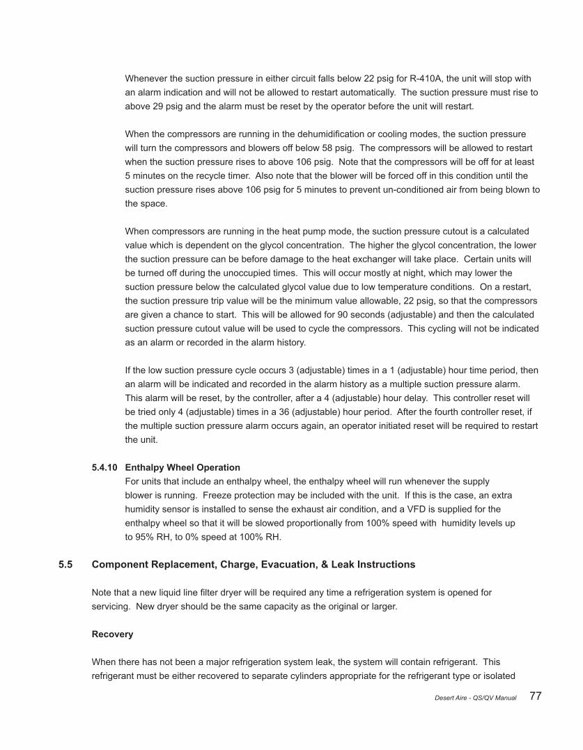
77Desert Aire - QS/QV Manual
Whenever the suction pressure in either circuit falls below 22 psig for R-410A, the unit will stop with an alarm indication and will not be allowed to restart automatically. The suction pressure must rise to above 29 psig and the alarm must be reset by the operator before the unit will restart.
Whenthecompressorsarerunninginthedehumidificationorcoolingmodes,thesuctionpressure will turn the compressors and blowers off below 58 psig. The compressors will be allowed to restart when the suction pressure rises to above 106 psig. Note that the compressors will be off for at least 5 minutes on the recycle timer. Also note that the blower will be forced off in this condition until the suction pressure rises above 106 psig for 5 minutes to prevent un-conditioned air from being blown to the space.
When compressors are running in the heat pump mode, the suction pressure cutout is a calculated value which is dependent on the glycol concentration. The higher the glycol concentration, the lower the suction pressure can be before damage to the heat exchanger will take place. Certain units will be turned off during the unoccupied times. This will occur mostly at night, which may lower the suction pressure below the calculated glycol value due to low temperature conditions. On a restart, the suction pressure trip value will be the minimum value allowable, 22 psig, so that the compressors are given a chance to start. This will be allowed for 90 seconds (adjustable) and then the calculated suction pressure cutout value will be used to cycle the compressors. This cycling will not be indicated as an alarm or recorded in the alarm history.
If the low suction pressure cycle occurs 3 (adjustable) times in a 1 (adjustable) hour time period, then an alarm will be indicated and recorded in the alarm history as a multiple suction pressure alarm. This alarm will be reset, by the controller, after a 4 (adjustable) hour delay. This controller reset will be tried only 4 (adjustable) times in a 36 (adjustable) hour period. After the fourth controller reset, if the multiple suction pressure alarm occurs again, an operator initiated reset will be required to restart the unit.
5.4.10 Enthalpy Wheel Operation For units that include an enthalpy wheel, the enthalpy wheel will run whenever the supply blower is running. Freeze protection may be included with the unit. If this is the case, an extra humidity sensor is installed to sense the exhaust air condition, and a VFD is supplied for the enthalpy wheel so that it will be slowed proportionally from 100% speed with humidity levels up to 95% RH, to 0% speed at 100% RH.
5.5 Component Replacement, Charge, Evacuation, & Leak Instructions
Notethatanewliquidlinefilterdryerwillberequiredanytimearefrigerationsystemisopenedfor servicing. New dryer should be the same capacity as the original or larger.
Recovery
When there has not been a major refrigeration system leak, the system will contain refrigerant. This refrigerant must be either recovered to separate cylinders appropriate for the refrigerant type or isolated

78 Desert Aire - QS/QV Manual
in a portion of the refrigeration system that will not be open for service. In all cases you must comply with Section 608 Refrigerant Recycling Rule of the Clean Air Act.
Recovery of Systems with Refrigeration System Leak
As much refrigerant as possible must be recovered into separate refrigerant cylinders appropriate for the refrigerant being serviced. System pressure near the leak site should be monitored closely to ensure this area is not pulled to a vacuum. Isolated sections of the system as required and recover independently to avoid refrigerant contamination. Uncontaminated refrigerant can be reused in the refrigeration system it was recovered from.
Recovery of Systems without a Leak
System that do not have leaks, but still require refrigeration system service, may have charge isolated in receivers and condensers if these particular components do not require direct service.
DesertAiredehumidifiershavedifferentreceiversizesdependingonthemodelandsize.Condenser sizesandconfigurationsmayalsovary.Ingeneral,largerreceiverswillcomeequippedwithisolation valves that will allow for a portion of the charge to be contained in the receiver during servicing. Units equipped with remote condensers will have isolation valves located inside the unit cabinet near the area where the connections are made.
The compressor can be used to move refrigerant to the system components that will be used to temporarily hold the charge. Note that cooling a condenser by running as many fans as possible and/or cooling the coil surface with a stream of water can assist in storing charge.
The low side pressure should be monitored closely while using this procedure to store charge. Under no circumstances should a compressor be allowed to run in a vacuum. When most of the refrigerant is isolated in the receiver and/or condensers, recover remaining charge into separate refrigerant cylinders approximate for the refrigerant being serviced. Carefully track the amount of refrigerant charge removed as this exact amount should be placed into the unit when re-charging.
Repair / Component Replacement
• If any portion of the system was at a vacuum, place dry nitrogen in the system until atmosphere pressure is reached.
• It is preferred that components are removed by heating the braze alloy to the re-melt temperature and mechanically moving the component. When this is not possible due to proximity of cabinet structure or other components, a tubing cutter can be used to remove sections of piping. Where new tube is required for replacement, use dehydrated tube where possible. Use the same type of fittingsasoriginal.Routethepipeintheexactmannerasoriginallyrouted.

79Desert Aire - QS/QV Manual
• Use Type K per ASTM B 88 or ASTM B 819 or Type ACR per ASTM B280 copper tubing or for all tubes 1 1/8” and smaller.
• Tubes 1 3/8” and larger shall use Type K per ASTM B 88 or ASTM B 819.
• Capsectionsoftubeandcomponentsthatarenotactivelybeinginstalledtopreventinfiltrationof moisture and contaminants.
• Use only braze alloy to join tube.
- Theselectionoffillermetalsishighlydependentonthetubefit,clearance,andoperator preferenceforflow.Whenfluxistobeused,careshouldbetakentoensurethatthefluxis not introduced to the inside of the tube. It is recommended that phosphorous bearing alloys beconsideredforcoppertocopperconnectionsduetotheirself-fluxingoncoppertocopper joints.Refertoalloymanufacturer’sguidelinesfordetailsoncompatibility.
• Flow nitrogen into tubing to prevent the formation of copper oxides.
- Copper oxides form rapidly when copper is heated to temperatures required by the brazing processandexposedtooxygenintheair.Copperoxidesflakeeasilyontheinsideofthe tubinganddislodgeeasilywhenthesystemisfilledwithrefrigerantandoil.Theparticulate can move throughout the system and cause contamination on valves and other critical components.Systemfiltersmaybecomefouled.
- Flowingnitrogenintothesystemandensuringthattheinsideofthetubeissignificantly free from oxygen while brazing ensures that oxides do not form. As the last joints of a system are made, additional thought must be made on the location where the nitrogen can escape. Schrader valves are placed throughout the system. These valves can be opened to allow for nitrogentoflowwithoutgeneratingpressurebehindthebrazejointthatisbeingcreated.
• See section 5.1.1 for special procedures related to compressor replacement
• Replaceliquidlinefilterdryeraslaststepinsystemrepair.Notethatthedryerwillreadilyabsorb moisture from the ambient air and must be open only for as long as required for installation.
• After completion of all repairs, pressure test system using nitrogen pressure decay test or nitrogen with tracer gas and appropriate leak detector.
Evacuation
• Carefully inspect pump and related equipment before connecting to system. Ensuring gaskets are in good condition and pump is capable of low vacuum levels can save time. Connect pump(s) to as manylocationsaspossibleensuringalllocationsarewellsealed.Ifafieldchargewillberequired,

80 Desert Aire - QS/QV Manual
connecting a refrigerant tank to the system with a good valve is recommended. Any hose connections requiring purging of non-condensable can be done at this point.
• Evacuate the line and remote condenser to 400 microns measured at a point on the system furthest away from the pump.
- Note that a gauge installed on the pump or in close proximity will give a lower reading while the unit is being evacuated.
• A deep vacuum gauge should be used to evaluate the pressure. Compound manifold gauges do not allow for enough accuracy at the pressures required.
- The system should be able to hold a vacuum under 500 microns for more than 10 minutes.
- If pressure continuously rises at a rapid rate there is likely a system leak. Review all piping connections and correct before continuing evacuation.
- Pressure rising above 500 microns and tending to stabilize at a higher pressure indicates the systemhasmoistureabovespecifications.Continueevacuationuntil500micronsorlower can be held for a minimum of 10 minutes.
Alternative Evacuation Specified by Process
After components have been repaired or replace evacuation procedure should take place. Very small amounts of refrigerant may still be mixed with the oil in the system. Out-gassing of this refrigerant may interfere with the evacuation and vacuum decay testing.
IF, AND ONLY IF, a unit has been previously charged with refrigerant, and standard evacuation method has not been successful after 24 hours minimum using the standard procedure, the following alternative method should be used.
1. Check vacuum level. It should be a maximum of 1,500 microns absolute pressure. If this is not the case, review system for leaks and continue evacuation process until 1,500 microns is achieved.
2. Purge system with nitrogen to atmospheric pressure (0 gauge pressure). Ensure all portions of systems are at this pressure. Seal system and wait 10 minutes.
3. Start vacuum pump and draw system to 1,500 microns or less.
4. Purge system with nitrogen to atmospheric pressure (0 gauge pressure). Ensure all portions of systems are at this pressure. Seal system and wait 10 minutes.
5. Start vacuum pump and draw system to 500 microns. Seal system. System may rise to higher level,

81Desert Aire - QS/QV Manual
but should not rise above 1000 microns in 10 minutes timeframe. If unsuccessful, continue evacuation or check for leaks.
It is anticipated that the system was clean and tight from the original process and refrigerant only is mixed with oil. Alternative process should not be considered if there is chance of free water entering the system or thesystemwasopenforanysignificanttime.
Charging
• Charge should be weighed into the system using a scale. In cases where the full charge was recovered, weigh in the charge with the recovered refrigerant and add the appropriate amount to meettheratingplateandfieldcharge(ifapplicable).Thisshouldbeplacedinthehighsideofthe system at the receiver.
• In cases where the full charge cannot be added to the system high side, the charge can be added to the low side of the system only when compressors are energized. If this is required, the compressors should be energized and the charge should be slowly metered into the suction line as far as possible upstream of the compressor. If the unit is equipped with an accumulator, the chargeneedstobeaddedtotheportupstreamofthislocation.Thebulkheadfittingsonthesideof the unit should not be used for charge addition. Monitor superheat at the compressor suction inlet usingthebulkheadfittingandatemperaturesensoronthesuctionlinenearthecompressor. Superheat should not drop below 10 degrees during the process of adding charge.
Testing and Final Diagnosis
Check the oil level in the compressor after the system has been running for 24 hours. Oil may have been contained in the liquid refrigerant when recovered from the system. Most of this oil will be returned if the recovered refrigerant is used. If new refrigerant is added, additional oil should be added based on the following ratio:
New Refrigerant Charge Added, lbs. x 0.352 = Oil charge, oz.
It is critically important to ensure that the system is operating as expected before unit is returned to normal service. Test component replaced and function of the system. Many times a separate component in the system may have set a condition that causes a failure of another. Thoroughly test systems to ensure repeat failures do not occur.
Note:Compressorssuppliedwithanoilsightglassshouldbeviewedandfilledto50%capacity.
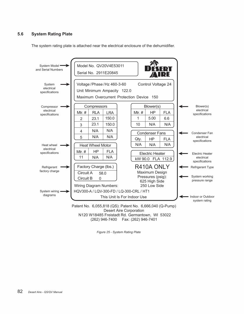
82
5.6 System Rating Plate
Thesystemratingplateisattachedneartheelectricalenclosureofthedehumidifier.
Figure 25 - System Rating Plate
Desert Aire - QS/QV Manual

83
5.7 Start-Up Supervision Supplemental Information
A Desert Aire factory start-up is an option which is normally purchased with the equipment. A factory start-up includes several key services:
• The expertise of an accomplished, factory-trained mechanic who will supervise the commissioning of the equipment.
• ThisDesertAirerepresentativewillassisttheinstallingcontractorwithfillingouttheStart-UpReport.
• Hewillalsoinspecttheinstallationtomakesurethatthedehumidifierhasbeenproperlyintegrated with the rest of the equipment on the jobsite.
• Finally, he can train the maintenance personnel to operate and service the equipment if necessary.
A factory start-up does not include installation assistance. The installing contractor is responsible for ensuring that the system is ready for start-up when the Desert-Aire representative arrives.
Whentheinstallingcontractorisconfidentthesystemwillbeready,heshouldcontacttheDesertAireSales representative to schedule the start-up. Please call at least two weeks before the desired start-up date to helppreventschedulingconflicts.
5.8 System Start-Up Report
Acopyofthesystem“Start-UpReport”canbefoundonthefollowingpages.Thisreportneedstobefilled outthoroughlybyaqualifiedservicetechnicianandreturnedtoDesertAireforwarrantyvalidation.Please ensure that the model and serial number of the unit are noted on this form. The model and serial number can befoundonthesystem’sratingplatelocatedonorneartheelectricalcompartmentservicedoor.Failureto completeandreturnthisformwillvoidtheunit’swarranty.Thesereportsarealsohelpfulwhentryingto correct existing problems. Should you need system diagnosis help, fax the completed worksheet to Desert Aire’sServiceDepartmentusingthenumberprovided.Besuretoincludeyournameandatelephone number where you can be reached.
Desert Aire - QS/QV Manual

84
Start-up request form for Total Aire unitsModels QS/QV
Factory Assisted Start-Up consists of a Desert Aire Service Department Technician to visit the job-site and provide supervisory experience to installing contractors as they perform the required procedures as outlined in our warranty activation start-up report. The company technician will also present an educational review of the dehumidifier’s operating and maintenance requirements. Factory Assisted Start-Up is not an installation bid & therefore the system must be ready to run before scheduling.
CST Start-Up is performed by a local Certified Service Technician who has been trained by Desert Aire. The CST performs all duties listed above. In addition they will supply the “items to be supplied for start-up” as listed below. Please note charges for refrigerant will apply if refrigerant is necessary to complete the start up.
Items to be completed by the installing contractor before any Start-Up can be scheduled: � Dehumidifier leak checked and inspected for internal concealed damage – remove access panels and inspect the interior of the unit for transit damage. Contact Desert Aire immediately if damage is noted (800) 443-5276 � Dehumidifier leveled and properly supported per the installation manuals recommendations. � Condensate P Trap installed with heat trace for winter operation. � Remote condenser plumbed, leak checked, evacuated, and charged if necessary. Some units require additional field charging. See unit labeling for details. Refrigerant added __________ lbs.(if applicable) � All electrical connections terminated and verified for proper voltage at the unit and the condenser (if applicable) � All field controls, sensors and actuators installed and circuits verified that they are wired correctly. If you have questions, contact Desert Aire for instructions (800) 443-5276. � Units with heat pump option – verify water flow and design temperature – See unit labeling for details. (if applicable) � Inspect all water lines for leaks and purge air from lines. (If applicable) � Verify that gas lines are installed, purged and set to the proper pressure – see label for gas pressure ratings (if applicable) Items to be supplied by the installing contractor (Factory Assisted Start-Up only) � Equipped service vehicle and service technician – Technician will be trained. � Refrigerant manifold gauges – 2 sets � Air balancing equipment (magnehelic or manometer differential pressure gauge – one inch scale) � Volt/Amp/OHM meters in working order. � Digital thermometer with sensors. � 50# of the appropriate refrigerant & scale. � Hand pump for adding oil to compressors.
If you are unable to supply any of the required equipment you must contact Desert Aire before returning this document.
I agree that all of the above has been completed as of _____________(Date) If a return trip must be scheduled due to insufficient job-site preparation an additional purchase order must be issued to Desert Aire for re-scheduling. A two week minimum is needed to schedule start-up. Once the form is completed please fax or email both pages to the Desert Aire service department. Fax (262) 946-7400 Email: [email protected]
Signature of responsible party: _________________________ (print) _________________________________________ (sign)
Company Name:__________________________________________ Phone #: ______________________________
N120 W18485 Freistadt RoadGermantown, WI 53022
(262) 946-7400 Fax: (262) 946-7401www.desert-aire.com
Desert Aire - QS/QV Manual
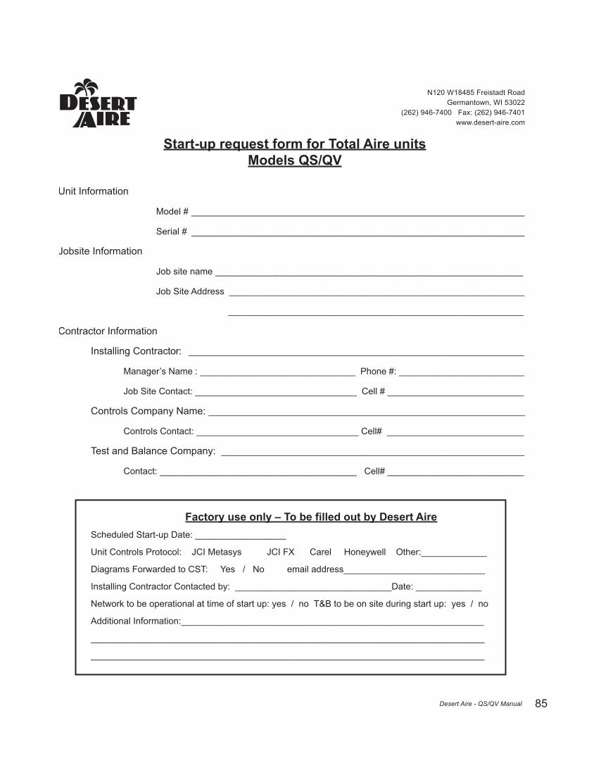
85
Start-up request form for Total Aire unitsModels QS/QV
Unit Information
Model # __________________________________________________________________
Serial # __________________________________________________________________
Jobsite Information
Job site name _____________________________________________________________
Job Site Address _________________________________________________________________
_________________________________________________________________
Contractor Information
Installing Contractor: ___________________________________________________________________
Manager’s Name : _______________________________ Phone #: _________________________
Job Site Contact: ________________________________ Cell # ___________________________
Controls Company Name: ______________________________________________________________
Controls Contact: ________________________________ Cell# ___________________________
Test and Balance Company: _____________________________________________________________
Contact: _______________________________________ Cell# ___________________________
Factory use only – To be filled out by Desert Aire Scheduled Start-up Date: __________________
Unit Controls Protocol: JCI Metasys JCI FX Carel Honeywell Other:_____________
Diagrams Forwarded to CST: Yes / No email address____________________________
Installing Contractor Contacted by: _______________________________Date: _____________
Network to be operational at time of start up: yes / no T&B to be on site during start up: yes / no
Additional Information:____________________________________________________________
______________________________________________________________________________
______________________________________________________________________________
N120 W18485 Freistadt RoadGermantown, WI 53022
(262) 946-7400 Fax: (262) 946-7401www.desert-aire.com
Desert Aire - QS/QV Manual

86 Desert Aire - QS/QV Manual
QS/QV Series Start up Report Important – To ensure warranty validation and continued customer satisfaction, complete
this form and return it to Desert Aire immediately after start-up. Validation of this report activates the warranty.
Desert Aire Corporation c/o Service and Warranty Department
N120W18485 Freistadt Road Germantown, WI 53022
(800) 443-5276
Instructions
• Warning – Only trained, qualified personnel should install and service Desert Aire equipment. Serious Injury or death can result from improper handling of this equipment. High voltage electrical components and refrigeration under pressure are present.
• Before continuing, read the Installation and Operations manual. If you do not fully understand the manual contact the Desert Aire Service Department. Please be prepared with the model and serial numbers located on the rating plate of the unit.
• Use one start up report per unit. Print or type all information. If there is not enough space available for readings or comments please attach additional pages directly to the start up report.
Location and Unit Information
Installation Name:
Installation Address:
Desert Aire Representative:
Dehumidifier Model #: Serial #:
Remote Condenser Model #: Serial #:
Form Completed By (Print): Signed:
Company Name: Date:
Company Address: Telephone #: ( )
Application:

87Desert Aire - QS/QV Manual
* Denotes that this is a model dependant item
Unit Power Supply InformationVoltage at
power block -No motors running
L1-L2 Control Voltage- No Motors
running
Transformer 1 VA Rating
L2-L3 Transformer 2 VA Rating
L1-L3 Transformer 3 VA Rating
Line-set Installation*This pertains to units with Remote Outdoor Condensers. Refer to Installation and operation
manual for instructionsLineset Length Elevation Change ABOVE / BELOW
Hot gas line trapped at every riser Yes / No Inverted traps at top of last riser Yes / No
Line-set pitched in direction of flow Yes / No Line-set Clamped per I/O Manual Yes / No
Line Sizes
Circuit A Circuit BHot Gas Hot Gas
Liquid Return Liquid Return
Additional R410A Added LBS LBS
Additional Oil Added OZS OZS
Fan Cycle Controller Settings*This pertains to units with Remote Outdoor Condensers. Refer to Installation and operation
manual for instructions.SENS SN-1 SN-2 SN-3
OUTR1ON1 OFF1 ONT1 OFT1 SNF1 SENS1
OUTR2ON2 OFF2 ONT2 OFT2 SNF2 SENS2
OUTR3ON3 OFF3 ONT3 OFT3 SNF3 SENS3
OUTR4ON4 OFF4 ONT4 OFT4 SNF4 SENS4
Proper Installation Checklist
□ Installation manual read and understood □ Tighten all field and factory
wiring □Open all refrigeration service valves and tighten packing nuts
□ Dehumidifier installed and leveled properly □ Adjust and tighten blower
belts if necessary □ Check field and factory piping for leaks
□ Condensate drain trapped and primed □ Check rotation of blower on 3
phase units □ Inspect air filters. Clean or replace as necessary
□ Verify that the power supply matches the rating plate □ Check rotation of remote
condenser fans. □ 120 volt circuit run to heat trace and powered up.
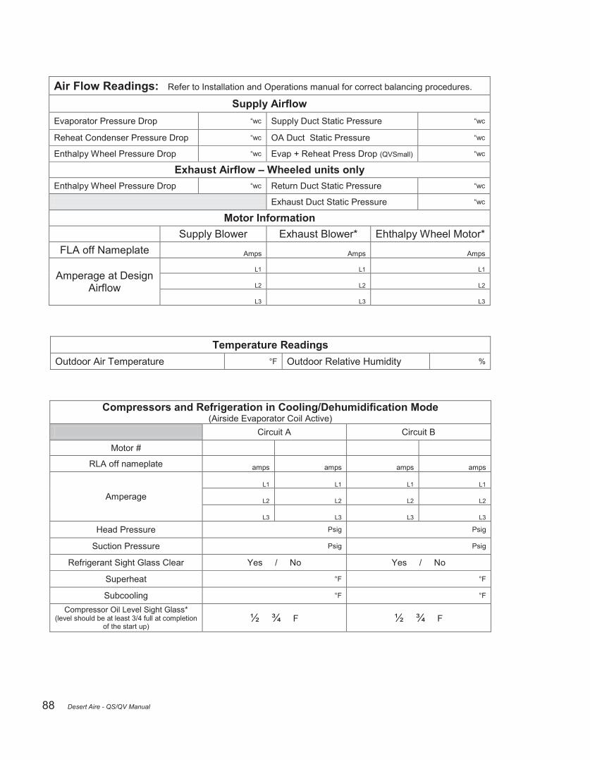
88 Desert Aire - QS/QV Manual
Temperature ReadingsOutdoor Air Temperature °F Outdoor Relative Humidity %
Air Flow Readings: Refer to Installation and Operations manual for correct balancing procedures.
Supply AirflowEvaporator Pressure Drop “wc Supply Duct Static Pressure “wc
Reheat Condenser Pressure Drop “wc OA Duct Static Pressure “wc
Enthalpy Wheel Pressure Drop “wc Evap + Reheat Press Drop (QVSmall) “wc
Exhaust Airflow – Wheeled units onlyEnthalpy Wheel Pressure Drop “wc Return Duct Static Pressure “wc
Exhaust Duct Static Pressure “wc
Motor InformationSupply Blower Exhaust Blower* Ehthalpy Wheel Motor*
FLA off Nameplate Amps Amps Amps
Amperage at Design Airflow
L1 L1 L1
L2 L2 L2
L3 L3 L3
Compressors and Refrigeration in Cooling/Dehumidification Mode(Airside Evaporator Coil Active)
Circuit A Circuit B
Motor #
RLA off nameplate amps amps amps amps
AmperageL1 L1 L1 L1
L2 L2 L2 L2
L3 L3 L3 L3
Head Pressure Psig Psig
Suction Pressure Psig Psig
Refrigerant Sight Glass Clear Yes / No Yes / No
Superheat °F °F
Subcooling °F °F
Compressor Oil Level Sight Glass*(level should be at least 3/4 full at completion
of the start up)½ ¾ F ½ ¾ F

89Desert Aire - QS/QV Manual
Water Flow Information*Circuit A Circuit B
Pipe SizeFlow Rate GPM GPM
Building Management System Information*Communication Type
(circle one) BACnet MS/TP - BACnet Ethernet - Modbus - Lon - N/A
BACnet MS/TP Device Instance
MAC AddressBaud Rate
BACnet Ethernet IP AddressNetmaskGateway
Modbus Baud RateAddress
Auxiliary Electric Heater Information*Signal L1 Amps L2 Amps L3 Amps Discharge Air Temp
Electric Heater °F
Auxiliary Water / Steam Coil Information*Signal Inlet Temp Outlet Temp Discharge Air Temp
Water Coil °F °F °F
Steam Coil °F °F °F
Compressors and Refrigeration in Heat Pump Mode*(Chiller Barrel Active)
Circuit A Circuit B
Head Pressure Psig Psig
Suction Pressure Psig Psig
Refrigerant Sight Glass Clear Yes / No Yes / No
Superheat °F °F
Subcooling °F °F
Water In Temperature* °F °F
Water Out Temperature* °F °F
Compressor Oil Level Sight Glass*(level should be at least 3/4 full at
completion of the start up)½ ¾ F ½ ¾ F

90
Additional Comments:
Desert Aire - QS/QV Manual

91Desert Aire - QS/QV Manual
Compressor Replacement Form
Location and Unit Information
Installation Name:
Dehumidifier Model #: Serial #:
Form Completed By (Print): Signed:
Company Name: Date:
Company Address: Phone #:
Fax #:
Defective Comp. Model #: Serial#: (If Tandem Set – Only list the specific failed compressor)
New Compressor Model #: Serial#:
Compressor Condition at Time of Initial Review Continuity (0 resistance) to Ground on one or more legs Compressor drawing higher current than design Continuity (0 resistance) between two or more legs (3 phase units) Compressor drawing locked rotor current
Other (describe): Runs without pumping: Pressures: _____ / _____
Continuity (0 resistance) to Ground on one or more legs Compressor drawing higher current than design Continuity (0 resistance) between two or more legs (3 phase units) Compressor drawing locked rotor current
Other (describe): Runs without pumping: Pressures: _____ / _____
Final Determination of Failure Liquid Floodback Low Superheat Debris Defective Expansion ValveLow Sump Oil Insufficient Motor Cooling Other (Describe):
Diagnostic/Corrective Action Summary Describe what corrective action was taken to prevent a repeat failure.
_________________________________________________________________________________________________
_________________________________________________________________________________________________
_________________________________________________________________________________________________
________________________________________________________________________________________________

92 Desert Aire - QS/QV Manual
Compressor Replacement Checklist Required Choose One For Test Results Showing Acid or Particulate
Acid and particulate test completed Unit Evacuated to 500 microns
absolute and vacuum decay passed HH Cores used – Acid Core
Liquid Line Filter Replaced Alternate triple evacuation
process used SF filter used
Air Flow Readings: Refer to Installation and Operations manual for correct balancing procedures.
Evaporator Static Pressure Drop “wc Supply Duct Static Pressure Drop “wc
Reheat Condenser Static Pressure Drop “wc Return Duct Static Pressure Drop “wc
Temperature Readings Room Air Temperature °F Water Temp (Circle: Pool / Tower) °F Room Relative Humidity %Outdoor Air Temperature °F Water Temp (Circle: Pool / Tower)* °F Outdoor Relative Humidity %
Compressors and Refrigeration in Reheat Mode Circuit A – Use both sides for tandem set Circuit B – Use both sides for tandem set
Motor # (See wiring schematic for details)
Discharge Pressure PSIG PSIG PSIG PSIGLiquid Line Pressure
(At access fitting nearest TXV) PSIG PSIG PSIG PSIGSuction Pressure (At compressor) PSIG PSIG PSIG PSIG
Liquid Line Temperature (At access fitting nearest TXV) °F °F °F °F
Suction Temperature (At Compressor) °F °F °F °F
Refrigerant Sight Glass Condition (Clear, Intermittent Vapor, Flashing)
Comp. Oil Level Sight Glass (Shut down comps., wait 5 minutes) ½ ¾ F ½ ¾ F ½ ¾ F ½ ¾ F
Compressors and Refrigeration in Cooling Mode Circuit A – Use both sides for tandem set Circuit B – Use both sides for tandem set
Motor # (See wiring schematic for details)
Discharge Pressure PSIG PSIG PSIG PSIGLiquid Line Pressure
(At access fitting nearest TXV) PSIG PSIG PSIG PSIGSuction Pressure (At compressor) PSIG PSIG PSIG PSIG
Liquid Line Temperature (At access fitting nearest TXV) °F °F °F °F
Suction Temperature (At Compressor) °F °F °F °F
Refrigerant Sight Glass Condition (Clear, Intermittent Vapor, Flashing)
Comp. Oil Level Sight Glass (Shut down comps., wait 5 minutes) ½ ¾ F ½ ¾ F ½ ¾ F ½ ¾ F

93Desert Aire - QS/QV Manual

94
OPTIMIZING SOLUTIONS THROUGH SUPERIOR DEHUMIDIFICATION TECHNOLOGY
N120 W18485 Freistadt Road • Germantown, WI 53022 • E-mail: [email protected]
Ph: (262) 946-7400 • Fax: (262) 946-7401 • Website: www.desert-aire.com
058 2018/12