Embed Size (px)
Citation preview

Airflow Measurementfor Acceptable
Indoor Air Quality Airflow Measurement for Today’s
GREEN Buildings

Airflow Measurementfor Acceptable
Indoor Air Quality
AS DESIGNERS WHY SHOULD YOU CARE ABOUT AIRFLOW
MEASURMENT?
Airflow Measurementfor Acceptable
Indoor Air Quality
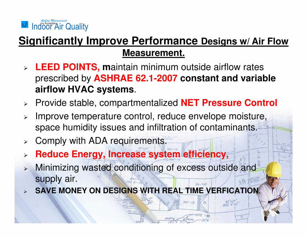
� LEED POINTS, maintain minimum outside airflow rates
prescribed by ASHRAE 62.1-2007 constant and variable airflow HVAC systems.
� Provide stable, compartmentalized NET Pressure Control
� Improve temperature control, reduce envelope moisture,
space humidity issues and infiltration of contaminants.
� Comply with ADA requirements.
� Reduce Energy, Increase system efficiency,
� Minimizing wasted conditioning of excess outside and
supply air.
� SAVE MONEY ON DESIGNS WITH REAL TIME VERFICATION.
Significantly Improve Performance Designs w/ Air Flow
Measurement.
Airflow Measurementfor Acceptable
Indoor Air Quality
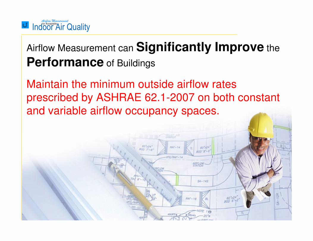
Maintain the minimum outside airflow rates
prescribed by ASHRAE 62.1-2007 on both constant
and variable airflow occupancy spaces.
Airflow Measurement can Significantly Improve the
Performance of Buildings
Airflow Measurementfor Acceptable
Indoor Air Quality ASHRAE 62.1-2010
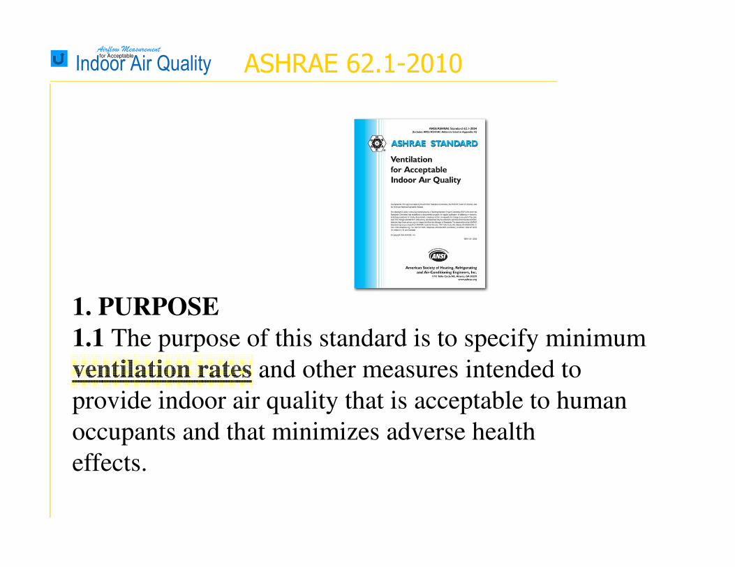
1. PURPOSE
1.1 The purpose of this standard is to specify minimum
ventilation rates and other measures intended to
provide indoor air quality that is acceptable to human
occupants and that minimizes adverse health
effects.
Airflow Measurementfor Acceptable
Indoor Air Quality
5.1.1 Designing for Air Balancing. The ventilation air
distribution system shall be provided with means
to adjust the system to achieve at least the minimum
ventilation airflow as required by Section 6 under
any load condition.
ASHRAE 62.1-2010
Airflow Measurementfor Acceptable
Indoor Air Quality
5.3 Ventilation System Controls. Mechanical ventilation
systems shall include controls, manual or
automatic, that enable the fan system to operate whenever
the spaces served are occupied. The system
shall be designed to maintain no less than the minimum
outdoor airflow as required by Section 6
under any load condition.
Note: Variable Air Volume (VAV) systems with fixed
outdoor air damper positions must comply
with this requirement at minimum system primary airflow.
ASHRAE 62.1-2010
Airflow Measurementfor Acceptable
Indoor Air Quality
6.1.1 Ventilation Rate Procedure. The prescriptive
design procedure presented in Section 6.2, in which
outdoor air intake rates are determined based on space
type/application, occupancy level, and floor area, shall
be permitted to be used for any zone or system.
6.1.2 IAQ Procedure. This performance-based design
procedure (presented in Section 6.3), in which the
building outdoor air intake rates and other system
design parameters are based on an analysis of
contaminant sources, contaminant concentration limits,
and level of perceived indoor air acceptability, shall be
permitted to be used for any zone or system.
ASHRAE 62.1-2010
Airflow Measurementfor Acceptable
Indoor Air Quality
Variety of effects on airflow
Uncontrolled Minimum Outside Air Intake Damper
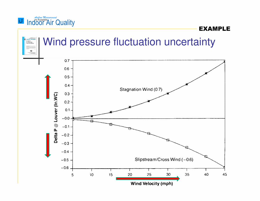
� Wind Effect
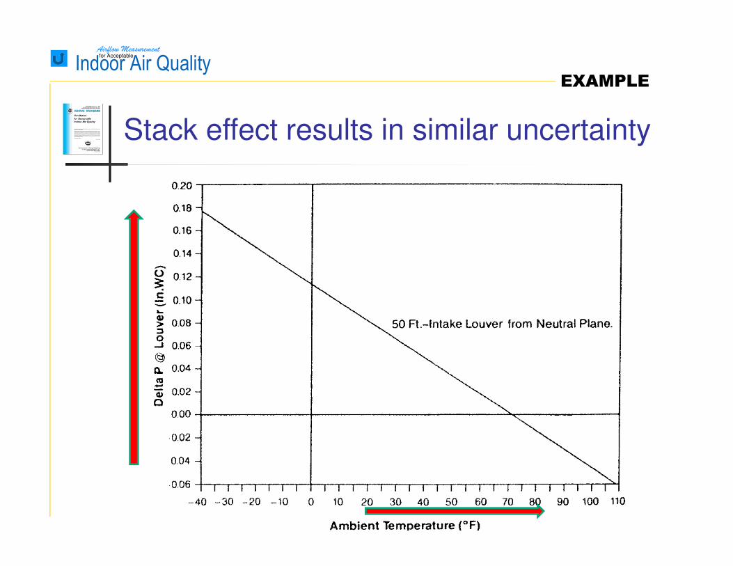
� Stack Effect
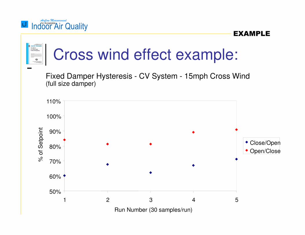
� Damper Hysteresis.
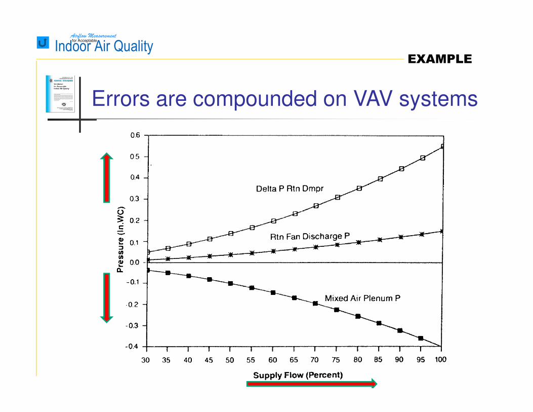
� Mixed air plenum pressure uncertainty
with any VAV system.
Techniques relying on damper position only
Airflow Measurementfor Acceptable
Indoor Air Quality
Wind pressure fluctuation uncertainty
EXAMPLE
Airflow Measurementfor Acceptable
Indoor Air Quality
Cross wind effect example:
EXAMPLE
Fixed Damper Hysteresis - CV System - 15mph Cross Wind(full size damper)
50%
60%
70%
80%
90%
100%
110%
1 2 3 4 5
Run Number (30 samples/run)
% o
f S
etp
oin
t
Close/Open
Open/Close
Airflow Measurementfor Acceptable
Indoor Air Quality
Stack effect results in similar uncertainty
EXAMPLE
Airflow Measurementfor Acceptable
Indoor Air Quality
Errors are compounded on VAV systems
EXAMPLE

Airflow Measurementfor Acceptable
Indoor Air Quality
Fixed Damper Hysterisis - CV System
(full size damper)
50%
60%
70%
80%
90%
100%
110%
1 2 3 4 5
Run Number (30 samples/run)
% o
f S
etp
oin
t
Close/Open
Open/Close
Regardless, Damper linkage hysteresis is
significant ……
EXAMPLE
Airflow Measurementfor Acceptable
Indoor Air Quality
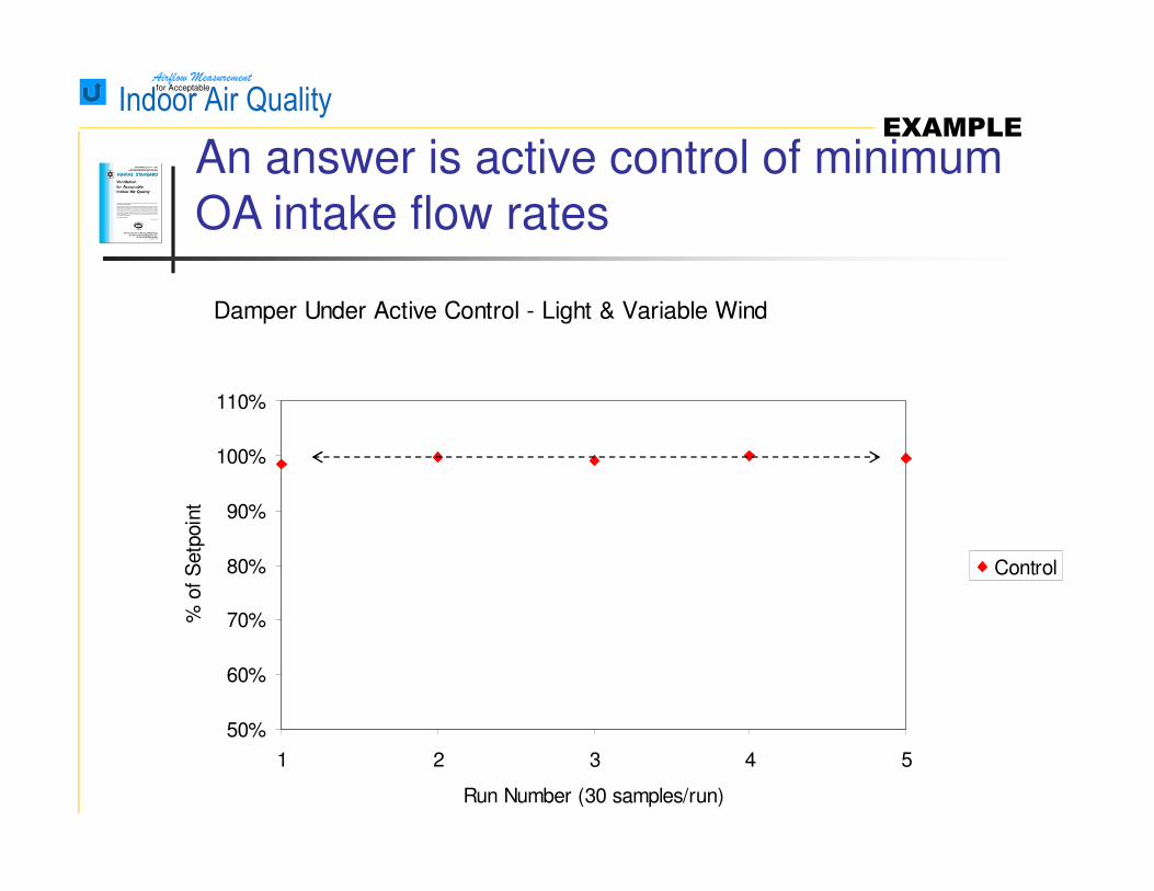
Damper Under Active Control - Light & Variable Wind
50%
60%
70%
80%
90%
100%
110%
1 2 3 4 5
Run Number (30 samples/run)
% o
f S
etp
oin
t
Control
An answer is active control of minimum OA intake flow rates
EXAMPLE
Airflow Measurementfor Acceptable
Indoor Air Quality
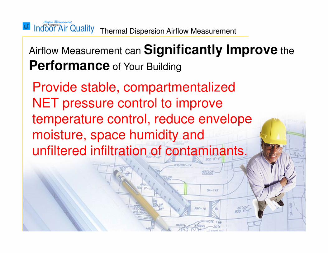
Provide stable, compartmentalized NET pressure control to improve temperature control, reduce envelope moisture, space humidity and unfiltered infiltration of contaminants.
Airflow Measurement can Significantly Improve the
Performance of Your Building
Thermal Dispersion Airflow Measurement
Airflow Measurementfor Acceptable
Indoor Air Quality
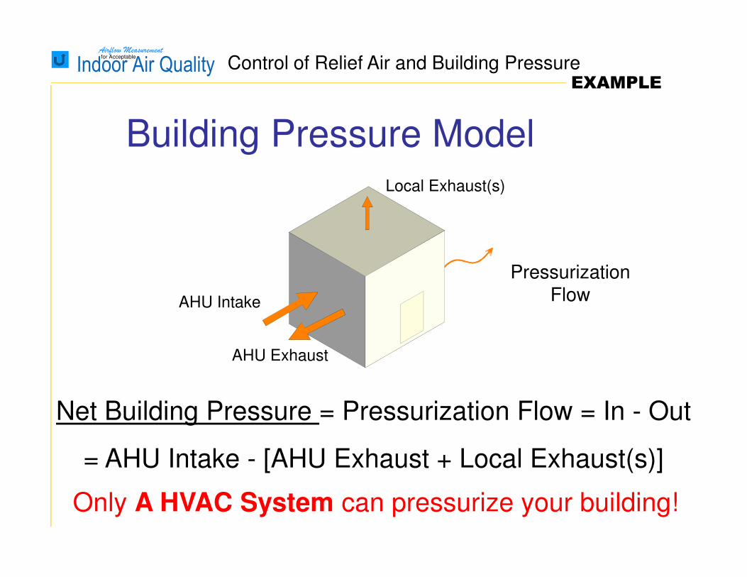
Net Building Pressure = Pressurization Flow = In - Out
= AHU Intake - [AHU Exhaust + Local Exhaust(s)]
AHU Exhaust
AHU Intake
Local Exhaust(s)
Pressurization Flow
Only A HVAC System can pressurize your building!
Building Pressure Model
Control of Relief Air and Building PressureEXAMPLE
Airflow Measurementfor Acceptable
Indoor Air Quality
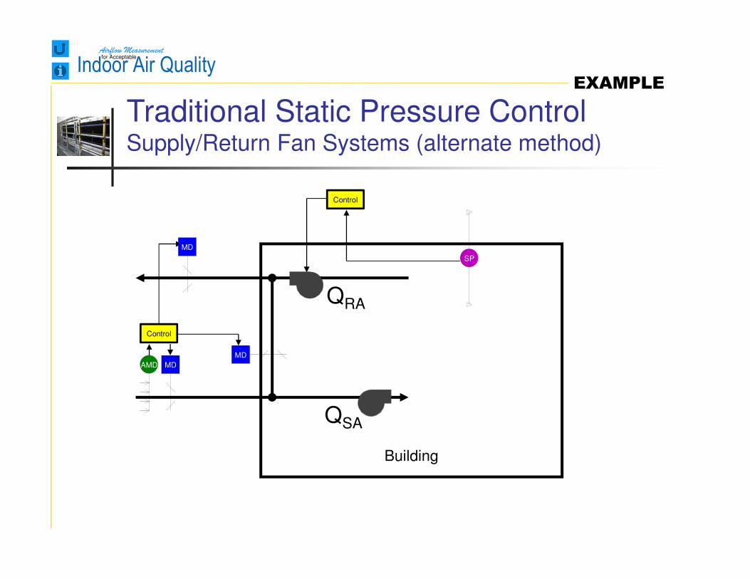
Building
QSA
QRA
Traditional Static Pressure ControlSupply/Return Fan Systems (alternate method)
MDAMD
MD
Control
SP
Control
MD
EXAMPLE
Airflow Measurementfor Acceptable
Indoor Air Quality
Building
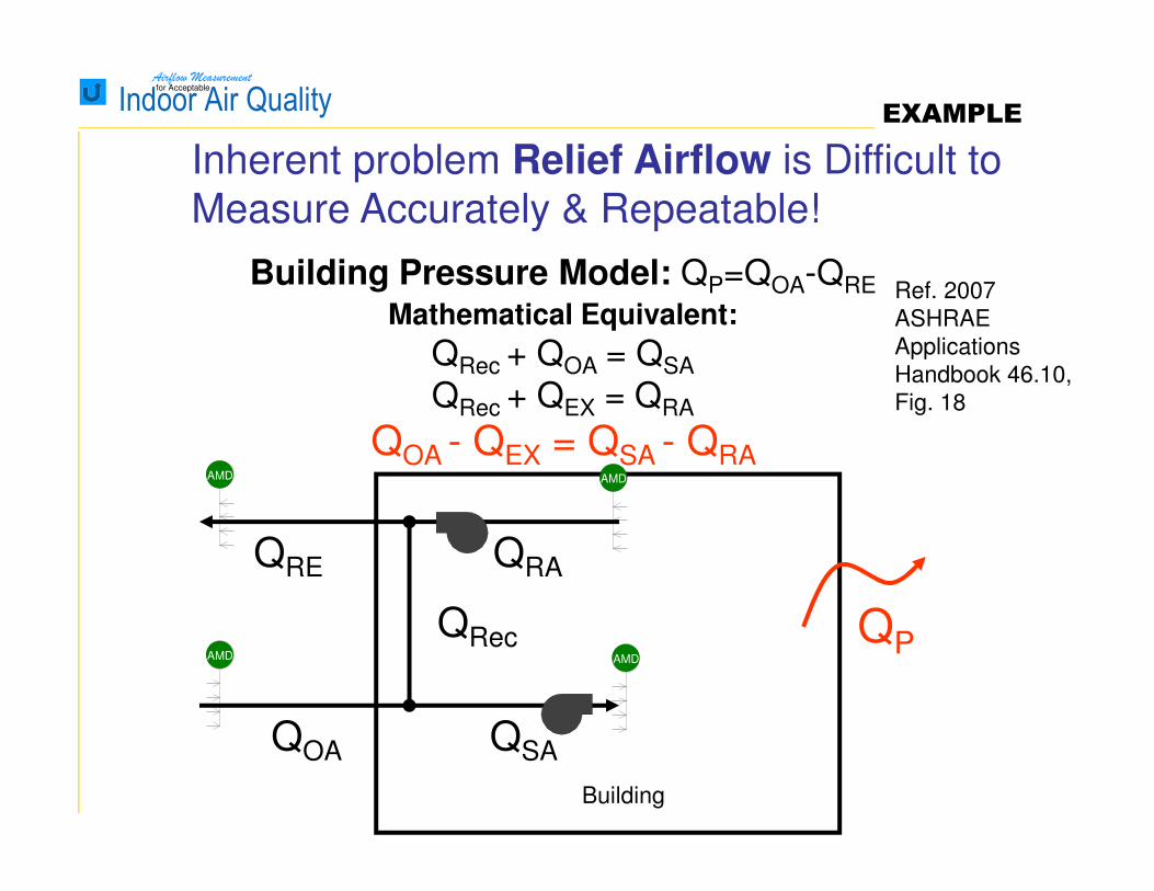
Building Pressure Model: QP=QOA-QRE
QP
QSA
QRAQRE
QOA
Mathematical Equivalent:
QRec + QOA = QSA
QRec + QEX = QRA
QOA - QEX = QSA - QRA
QRec
Inherent problem Relief Airflow is Difficult to
Measure Accurately & Repeatable!
AMD
AMD
AMD
AMD
Ref. 2007
ASHRAE
Applications
Handbook 46.10,
Fig. 18
EXAMPLE

Airflow Measurementfor Acceptable
Indoor Air Quality
Building
Building Pressure Model: QP=QSA-QRA
QP
QSA
QRA
Traditional Pressure Solution
Control
AMDMDAMD
MD
Control
AMD2
Pos
Ref. 2007
ASHRAE
Applications
Handbook
46.10, Fig. 18
EXAMPLE
Airflow Measurementfor Acceptable
Indoor Air Quality
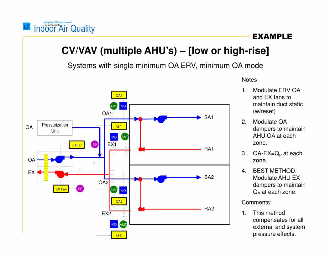
CV/VAV (multiple AHU’s) – [low or high-rise]
Systems with single minimum OA ERV, minimum OA mode
Notes:
1. Modulate ERV OA and EX fans to maintain duct static (w/reset)
2. Modulate OA dampers to maintain AHU OA at each zone.
3. OA-EX=QP at each zone.
4. BEST METHOD: Modulate AHU EX dampers to maintain QP at each zone.
Comments:
1. This method compensates for all external and system pressure effects.
OA
RA1
SA1
EX
RA2
SA2
OA1
EX1
OA2
EX2
Pressurization
UnitOA
MD
MD
SPOAFan
OA2
AMD
AMD
OA1
MD
MD
QP1
SP
QP2
EX Fan
AMD
AMD
EXAMPLE
Airflow Measurementfor Acceptable
Indoor Air Quality
Reduce energy by increasing
system efficiency while
simultaneously minimizing
wasted conditioning of excess
outside and supply air.
Airflow Measurement can Significantly Improve the
Performance of Your Building
EXAMPLE
Airflow Measurementfor Acceptable
Indoor Air Quality
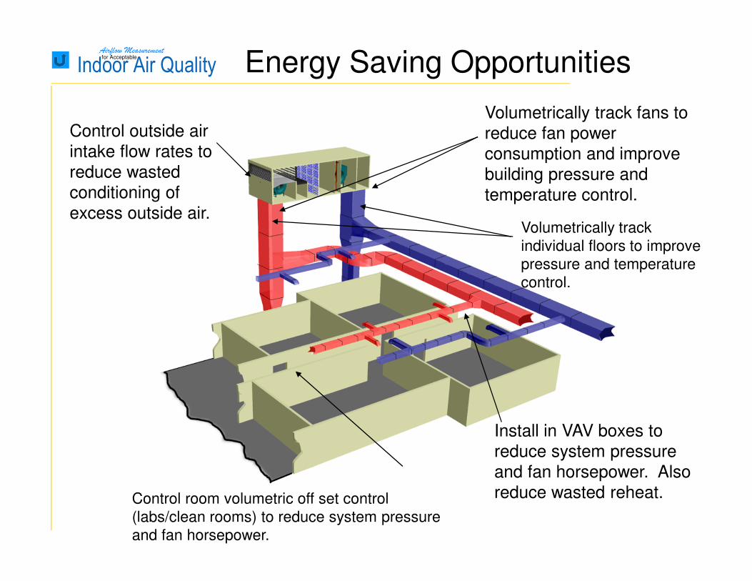
Volumetrically track fans to
reduce fan power
consumption and improve
building pressure and
temperature control.
Control outside air
intake flow rates to
reduce wasted
conditioning of
excess outside air.Volumetrically track
individual floors to improve
pressure and temperature
control.
Install in VAV boxes to
reduce system pressure
and fan horsepower. Also
reduce wasted reheat.Control room volumetric off set control
(labs/clean rooms) to reduce system pressure
and fan horsepower.
Energy Saving Opportunities

Airflow Measurementfor Acceptable
Indoor Air Quality
Provide a sustainable
design by assuring design
performance over the life of
the building.
Airflow Measurement can Significantly Improve the
Performance of Your Building
Airflow Measurementfor Acceptable
Indoor Air Quality
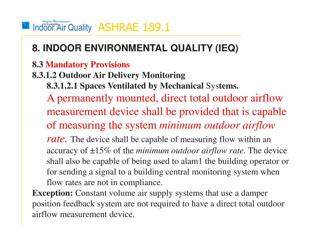
8. INDOOR ENVIRONMENTAL QUALITY (IEQ)
8.3 Mandatory Provisions
8.3.1.2 Outdoor Air Delivery Monitoring
8.3.1.2.1 Spaces Ventilated by Mechanical Systems.
A permanently mounted, direct total outdoor airflow
measurement device shall be provided that is capable
of measuring the system minimum outdoor airflow
rate. The device shall be capable of measuring flow within an
accuracy of ±15% of the minimum outdoor airflow rate. The device
shall also be capable of being used to alam1 the building operator or
for sending a signal to a building central monitoring system when
flow rates are not in compliance.
Exception: Constant volume air supply systems that use a damper
position feedback system are not required to have a direct total outdoor
airflow measurement device.
ASHRAE 189.1
Airflow Measurementfor Acceptable
Indoor Air Quality
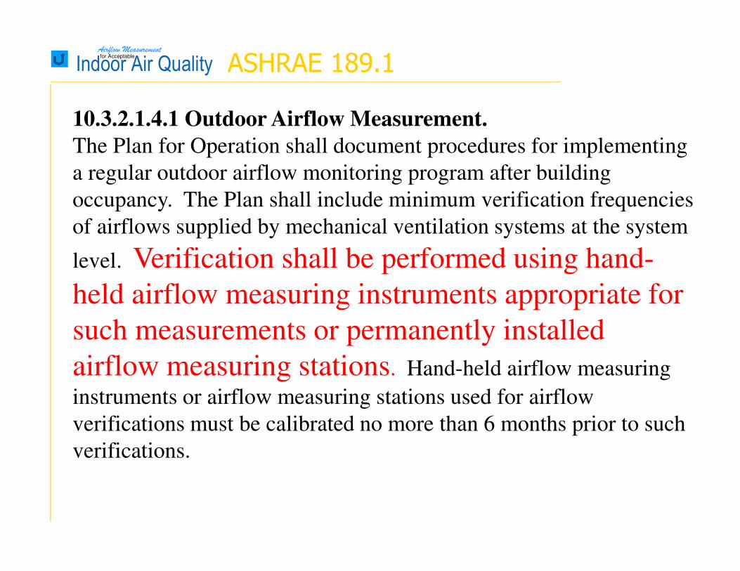
10.3.2.1.4.1 Outdoor Airflow Measurement.
The Plan for Operation shall document procedures for implementing
a regular outdoor airflow monitoring program after building
occupancy. The Plan shall include minimum verification frequencies
of airflows supplied by mechanical ventilation systems at the system
level. Verification shall be performed using hand-
held airflow measuring instruments appropriate for
such measurements or permanently installed
airflow measuring stations. Hand-held airflow measuring
instruments or airflow measuring stations used for airflow
verifications must be calibrated no more than 6 months prior to such
verifications.
ASHRAE 189.1

Airflow Measurementfor Acceptable
Indoor Air Quality
10.3.2.1.4.2 Outdoor Airflow Verification Procedures. The plan
procedures shall contain the following requirements:
a. For each mechanical ventilation system where direct outdoor airflow
measurement is required according to Section 8.3.1.2, a procedure shall
be in place to react when the outdoor airflow is 15% or more lower
than minimum outdoor airflow rate. It shall be verified that the device
that measures outdoor air flow rate is actually measuring the flow rate
within ±15% of the sensor output reading at the minimum outdoor
airflow rate. If the sensor is not within ±15%, it shall be recalibrated.
Verification of outdoor airflow shall be done on a
quarterly basis and records maintained onsite. Direct
outdoor airflow measurement devices shall be
calibrated at the manufacturer's recommended interval
or at least annually.
ASHRAE 189.1
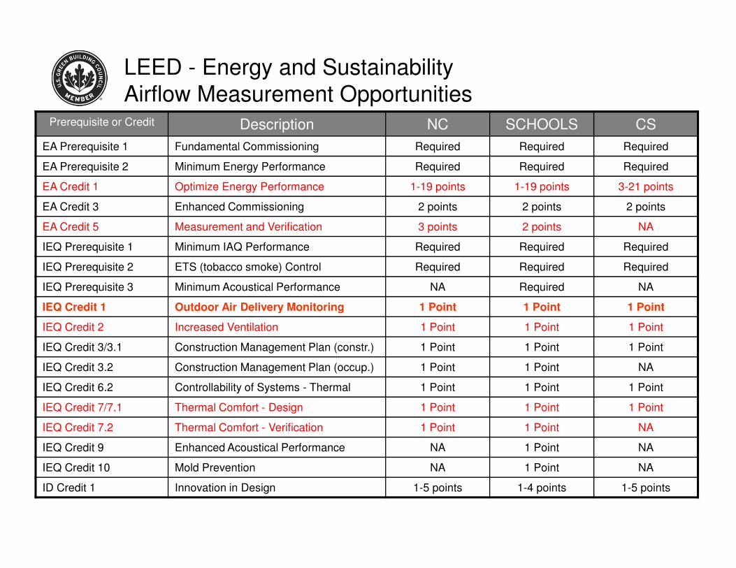
LEED - Energy and Sustainability
Airflow Measurement OpportunitiesPrerequisite or Credit Description NC SCHOOLS CS
EA Prerequisite 1 Fundamental Commissioning Required Required Required
EA Prerequisite 2 Minimum Energy Performance Required Required Required
EA Credit 1 Optimize Energy Performance 1-19 points 1-19 points 3-21 points
EA Credit 3 Enhanced Commissioning 2 points 2 points 2 points
EA Credit 5 Measurement and Verification 3 points 2 points NA
IEQ Prerequisite 1 Minimum IAQ Performance Required Required Required
IEQ Prerequisite 2 ETS (tobacco smoke) Control Required Required Required
IEQ Prerequisite 3 Minimum Acoustical Performance NA Required NA
IEQ Credit 1 Outdoor Air Delivery Monitoring 1 Point 1 Point 1 Point
IEQ Credit 2 Increased Ventilation 1 Point 1 Point 1 Point
IEQ Credit 3/3.1 Construction Management Plan (constr.) 1 Point 1 Point 1 Point
IEQ Credit 3.2 Construction Management Plan (occup.) 1 Point 1 Point NA
IEQ Credit 6.2 Controllability of Systems - Thermal 1 Point 1 Point 1 Point
IEQ Credit 7/7.1 Thermal Comfort - Design 1 Point 1 Point 1 Point
IEQ Credit 7.2 Thermal Comfort - Verification 1 Point 1 Point NA
IEQ Credit 9 Enhanced Acoustical Performance NA 1 Point NA
IEQ Credit 10 Mold Prevention NA 1 Point NA
ID Credit 1 Innovation in Design 1-5 points 1-4 points 1-5 points
Airflow Measurementfor Acceptable
Indoor Air Quality
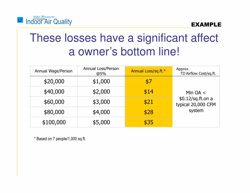
These losses have a significant affect
a owner’s bottom line!
* Based on 7 people/1,000 sq.ft.
Approx.
TD
EXAMPLE
Annual Wage/PersonAnnual Loss/Person
@5%Annual Loss/sq.ft.*
Airflow Cost/sq.ft.
$20,000 $1,000 $7
$40,000 $2,000 $14
$60,000 $3,000 $21
$80,000 $4,000 $28
$100,000 $5,000 $35
Min OA <
$0.12/sq.ft.on a
typical 20,000 CFM
system
Airflow Measurementfor Acceptable
Indoor Air Quality
Airflow Measurement Technologies ?
TechnologyTechnology Review
Airflow Measurementfor Acceptable
Indoor Air Quality
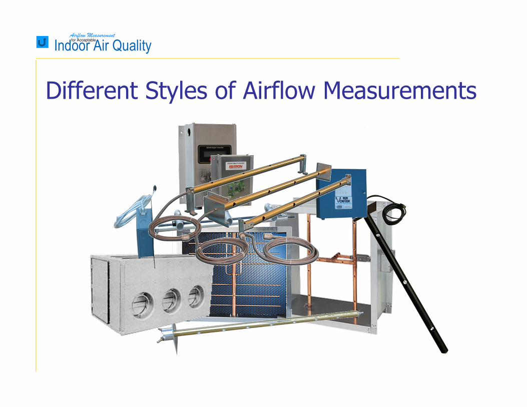
Different Styles of Airflow Measurements
Airflow Measurementfor Acceptable
Indoor Air Quality
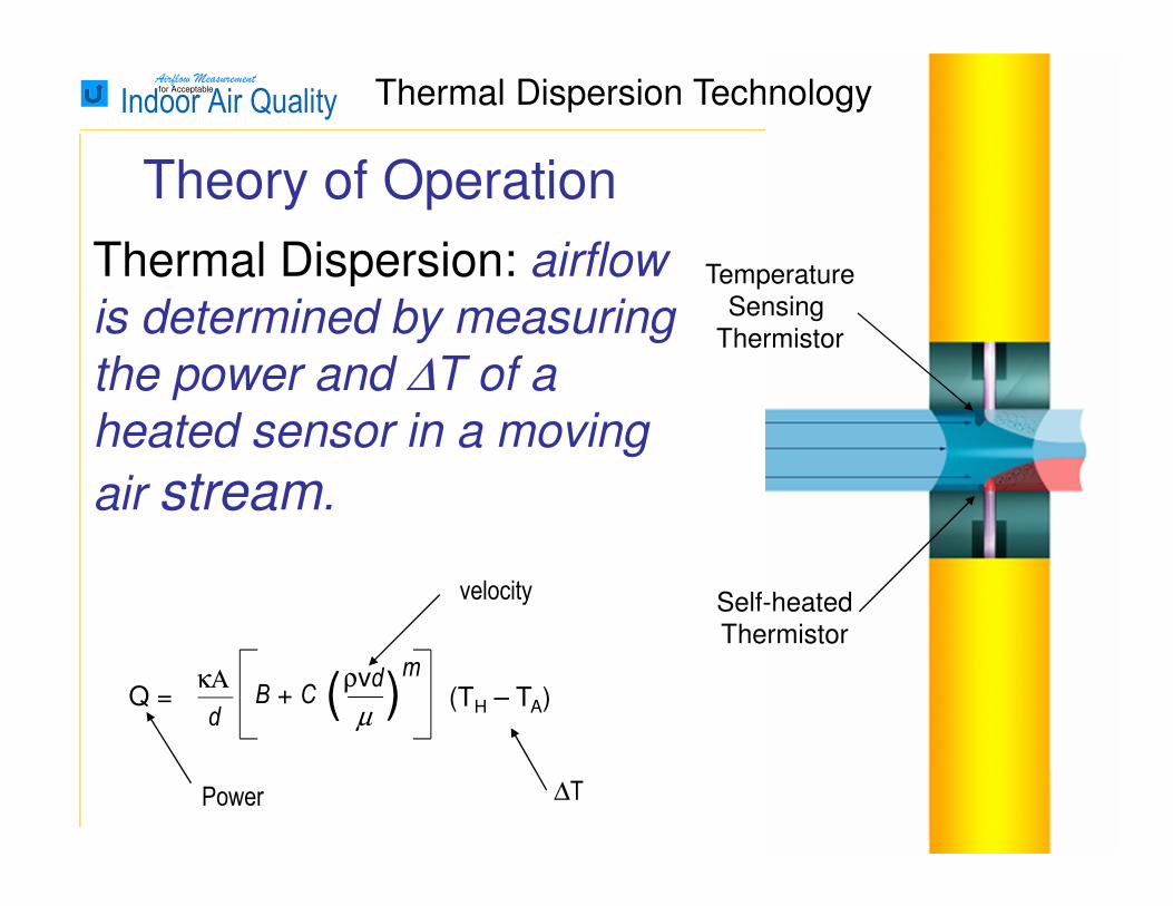
Theory of Operation
Q = κΑ
dB + C (ρvd
µ)
m
(TH – TA)
Thermal Dispersion: airflow
is determined by measuring
the power and ∆T of a
heated sensor in a moving
air stream.
Power ∆T
velocity
Temperature
Sensing
Thermistor
Self-heated
Thermistor
Thermal Dispersion Technology
Airflow Measurementfor Acceptable
Indoor Air Quality
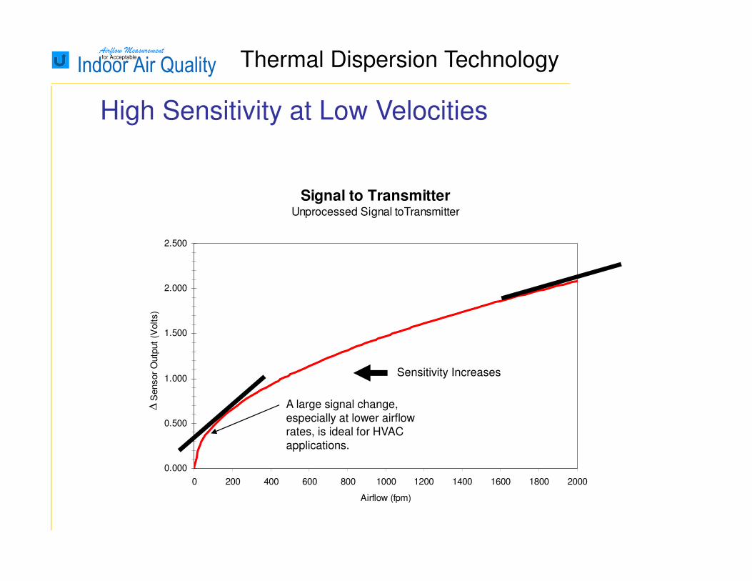
Signal to TransmitterUnprocessed Signal toTransmitter
0.000
0.500
1.000
1.500
2.000
2.500
0 200 400 600 800 1000 1200 1400 1600 1800 2000
Airflow (fpm)
Sensor
Outp
ut
(Volts)
Sensor
Outp
ut
(in.w
.g.)
High Sensitivity at Low Velocities
A large signal change,
especially at lower airflow
rates, is ideal for HVAC
applications.
Sensitivity Increases
∆
Thermal Dispersion Technology
Airflow Measurementfor Acceptable
Indoor Air Quality
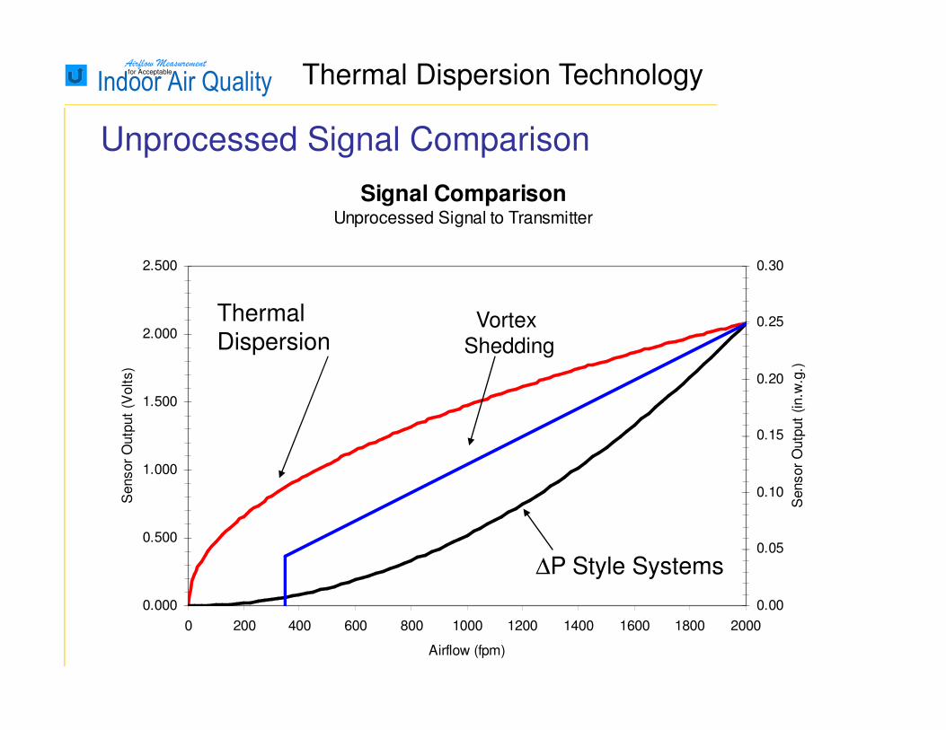
Signal ComparisonUnprocessed Signal to Transmitter
0.000
0.500
1.000
1.500
2.000
2.500
0 200 400 600 800 1000 1200 1400 1600 1800 2000
Airflow (fpm)
Sensor
Outp
ut
(Volts)
0.00
0.05
0.10
0.15
0.20
0.25
0.30
Sensor
Outp
ut
(in.w
.g.)
Unprocessed Signal Comparison
Vortex
Shedding
∆P Style Systems
Thermal Dispersion
Thermal Dispersion Technology

Airflow Measurementfor Acceptable
Indoor Air Quality
0.000
0.500
1.000
1.500
2.000
2.500
3.000
3.500
0 500 1000 1500 2000 2500 3000 3500 4000 4500 5000
Airflow (fpm)
Sensor
Outp
ut (V
olts)
0.0
2.0
1.8
∆
Multi-point Factory Calibration to NIST Traceable Standards
Thermal Dispersion Technology

Airflow Measurementfor Acceptable
Indoor Air Quality Long Term Stability
-2.0%
-1.5%
-1.0%
-0.5%
0.0%
0.5%
1.0%
1.5%
2.0%
-3000 -2500 -2000 -1500 -1000 -500 0
Days
% A
irfl
ow
Err
or
(of
read
ing
)
5000 FPM
2000 FPM
1000 FPM
100 FPM
Composite
7 years and counting

Airflow Measurementfor Acceptable
Indoor Air Quality
Average & Output
Calculate Airflow
& Temperature
Calculate Airflow
& Temperature
Calculate Airflow
& Temperature
Calculate Airflow
& Temperature
Convert Voltages
to Binary
Convert Voltages
to Binary
Convert Voltages
to Binary
Convert Voltages
to Binary
No Averaging Error
Thermal Dispersion Technology
Airflow Measurementfor Acceptable
Indoor Air Quality
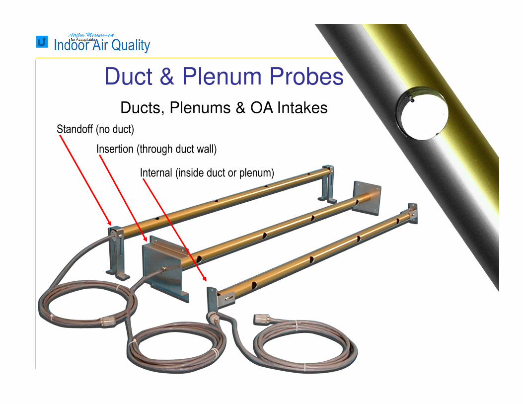
Standoff (no duct)
Insertion (through duct wall)
Internal (inside duct or plenum)
Duct & Plenum Probes
Ducts, Plenums & OA Intakes
Airflow Measurementfor Acceptable
Indoor Air Quality
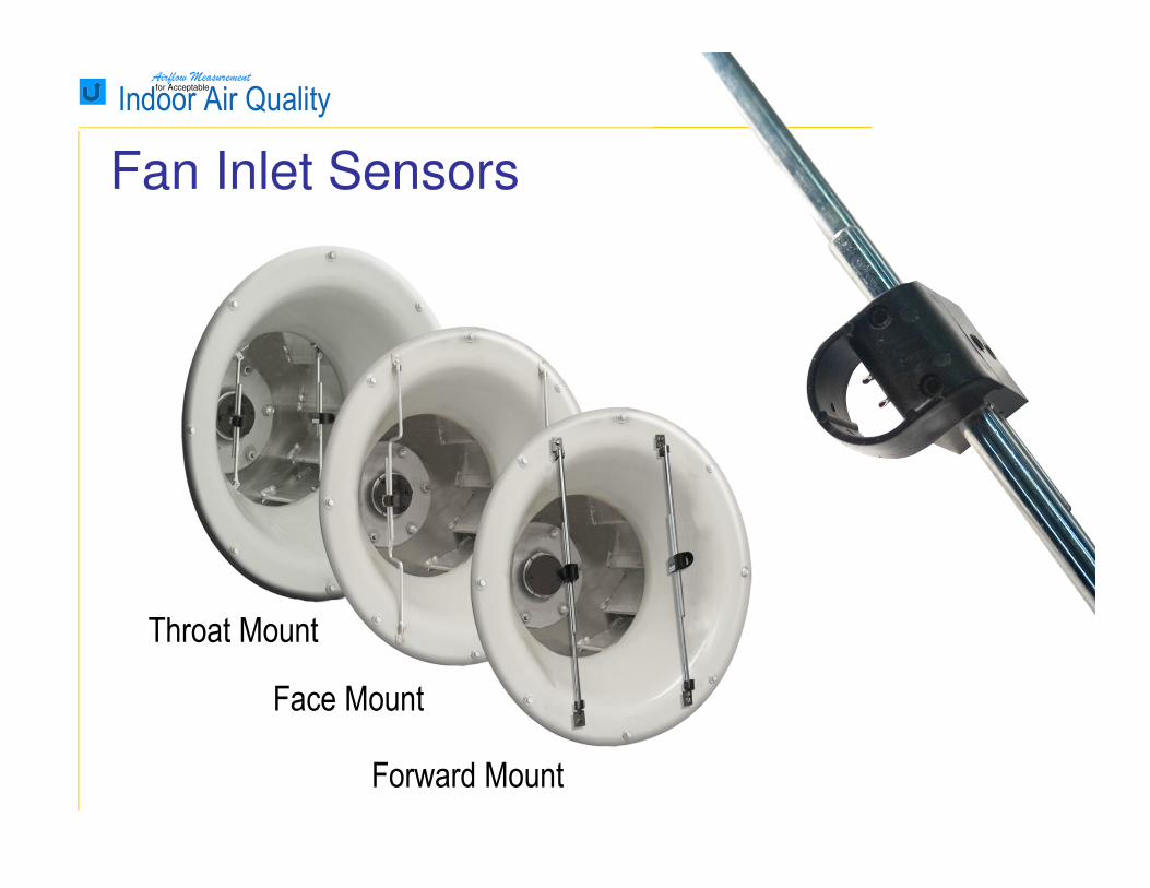
Throat Mount
Face Mount
Forward Mount
Fan Inlet Sensors
Airflow Measurementfor Acceptable
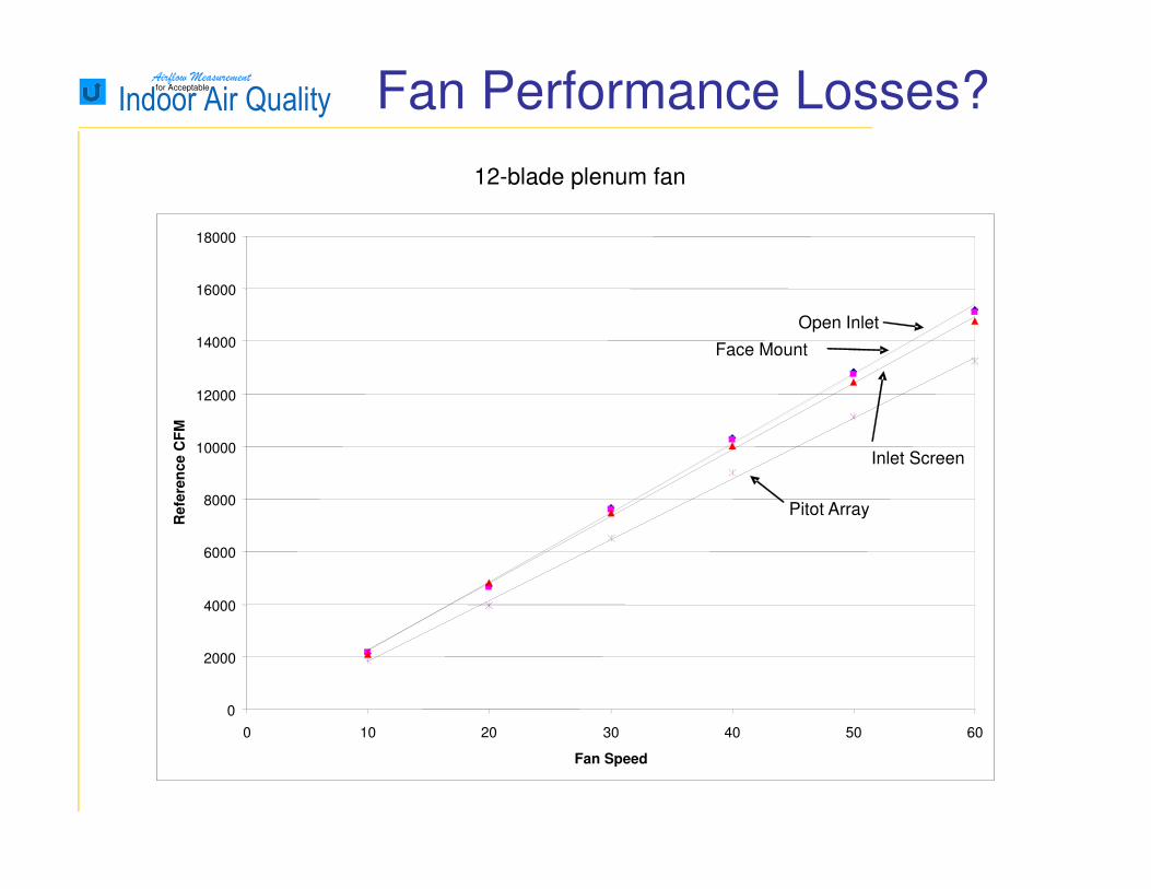
Indoor Air Quality Fan Performance Losses?
12-blade plenum fan
0
2000
4000
6000
8000
10000
12000
14000
16000
18000
0 10 20 30 40 50 60
Fan Speed
Refe
ren
ce C
FM
Open Inlet
Face Mount
Inlet Screen
Pitot Array

Airflow Measurementfor Acceptable
Indoor Air Quality
Averaging Pitot Array Stations with Honeycomb
Averaging Pitot Array Probes
Combination Pitot Array/Damper with Honeycomb
Combination Pitot Array & Dampers
∆P Across Louver
Air Monitor Corporation, FAN-E
Trane, Traq Damper
Ruskin, IAQ-50
Piezo Fan Inlet Rings
∆∆∆∆P Style Products

Airflow Measurementfor Acceptable
Indoor Air Quality
Total Pressure Inlet
Static Pressure Inlets
Total Pressure Tap
Static Pressure Tap
∆p=ptotal-pstatic
V=4005 x ∆p√
√V=k2∆pgc
ρ
Traditional Pitot Tubes and Arrays
Note: Accuracy is dependent on:
1. Pressure transducer performance.
2. Air density
3. Turndown
PITOT-STATIC TUBES vs. VELOCITY PRESSURE ARRAY
Airflow Measurementfor Acceptable
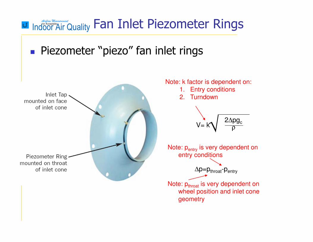
Indoor Air Quality Fan Inlet Piezometer Rings
� Piezometer “piezo” fan inlet rings
∆p=pthroat-pentry
√V= k2∆pgc
ρ
Note: k factor is dependent on:
1. Entry conditions
2. Turndown
Note: pentry is very dependent on
entry conditions
Note: pthroat is very dependent on
wheel position and inlet cone
geometry
Airflow Measurementfor Acceptable
Indoor Air Quality
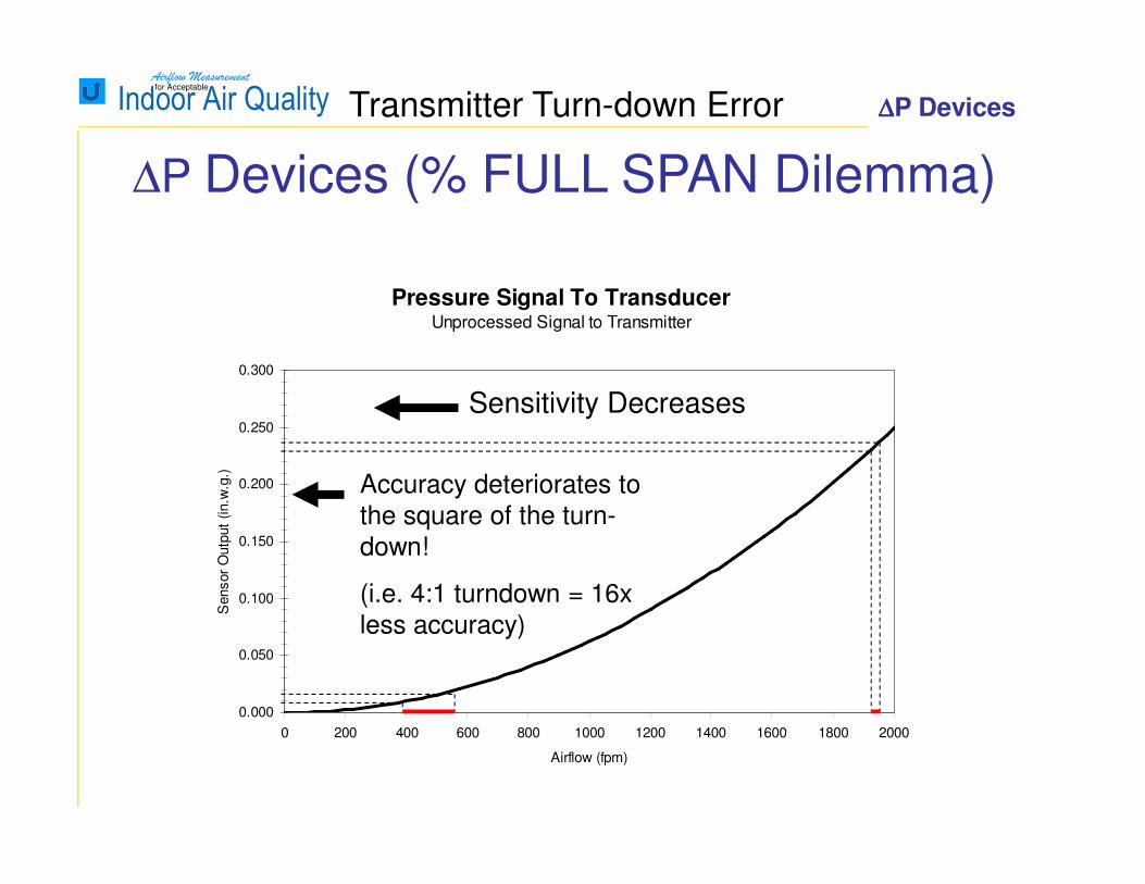
Pressure Signal To TransducerUnprocessed Signal to Transmitter
0.000
0.050
0.100
0.150
0.200
0.250
0.300
0 200 400 600 800 1000 1200 1400 1600 1800 2000
Airflow (fpm)
Sensor
Outp
ut
(in.w
.g.)
∆P Devices (% FULL SPAN Dilemma)
Transmitter Turn-down Error
Accuracy deteriorates to
the square of the turn-
down!
(i.e. 4:1 turndown = 16x
less accuracy)
∆∆∆∆P Devices
Sensitivity Decreases

Airflow Measurementfor Acceptable
Indoor Air Quality
≠≠≠≠0.1% of Full Scale 1% of Full Scale
∆P TRANDUCERS ARE NOT ALIKE
Airflow Measurementfor Acceptable
Indoor Air Quality
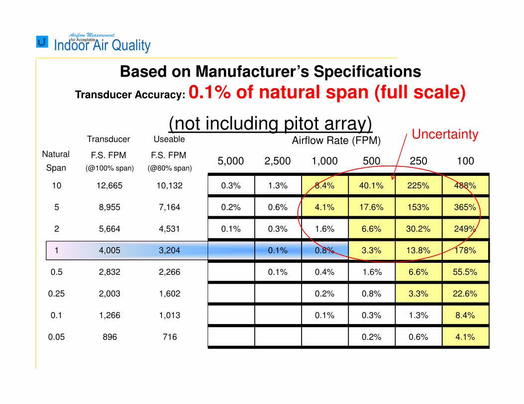
Based on Manufacturer’s Specifications
Transducer Accuracy: 0.1% of natural span (full scale)
(not including pitot array)Transducer Useable
Natural
Span
F.S. FPM
(@100% span)
F.S. FPM
(@80% span)5,000 2,500 1,000 500 250 100
10 12,665 10,132 0.3% 1.3% 8.4% 40.1% 225% 488%
5 8,955 7,164 0.2% 0.6% 4.1% 17.6% 153% 365%
2 5,664 4,531 0.1% 0.3% 1.6% 6.6% 30.2% 249%
1 4,005 3,204 0.1% 0.8% 3.3% 13.8% 178%
0.5 2,832 2,266 0.1% 0.4% 1.6% 6.6% 55.5%
0.25 2,003 1,602 0.2% 0.8% 3.3% 22.6%
0.1 1,266 1,013 0.1% 0.3% 1.3% 8.4%
0.05 896 716 0.2% 0.6% 4.1%
Airflow Rate (FPM)Uncertainty
Airflow Measurementfor Acceptable
Indoor Air Quality
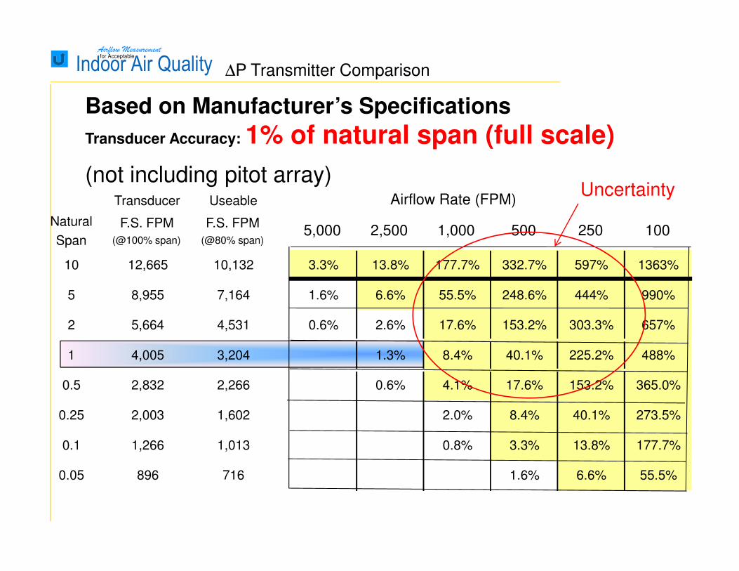
Based on Manufacturer’s Specifications
Transducer Accuracy: 1% of natural span (full scale)
(not including pitot array)
∆P Transmitter Comparison
Transducer Useable
Natural
Span
F.S. FPM
(@100% span)
F.S. FPM
(@80% span)5,000 2,500 1,000 500 250 100
10 12,665 10,132 3.3% 13.8% 177.7% 332.7% 597% 1363%
5 8,955 7,164 1.6% 6.6% 55.5% 248.6% 444% 990%
2 5,664 4,531 0.6% 2.6% 17.6% 153.2% 303.3% 657%
1 4,005 3,204 1.3% 8.4% 40.1% 225.2% 488%
0.5 2,832 2,266 0.6% 4.1% 17.6% 153.2% 365.0%
0.25 2,003 1,602 2.0% 8.4% 40.1% 273.5%
0.1 1,266 1,013 0.8% 3.3% 13.8% 177.7%
0.05 896 716 1.6% 6.6% 55.5%
Airflow Rate (FPM)Uncertainty
Airflow Measurementfor Acceptable
Indoor Air Quality
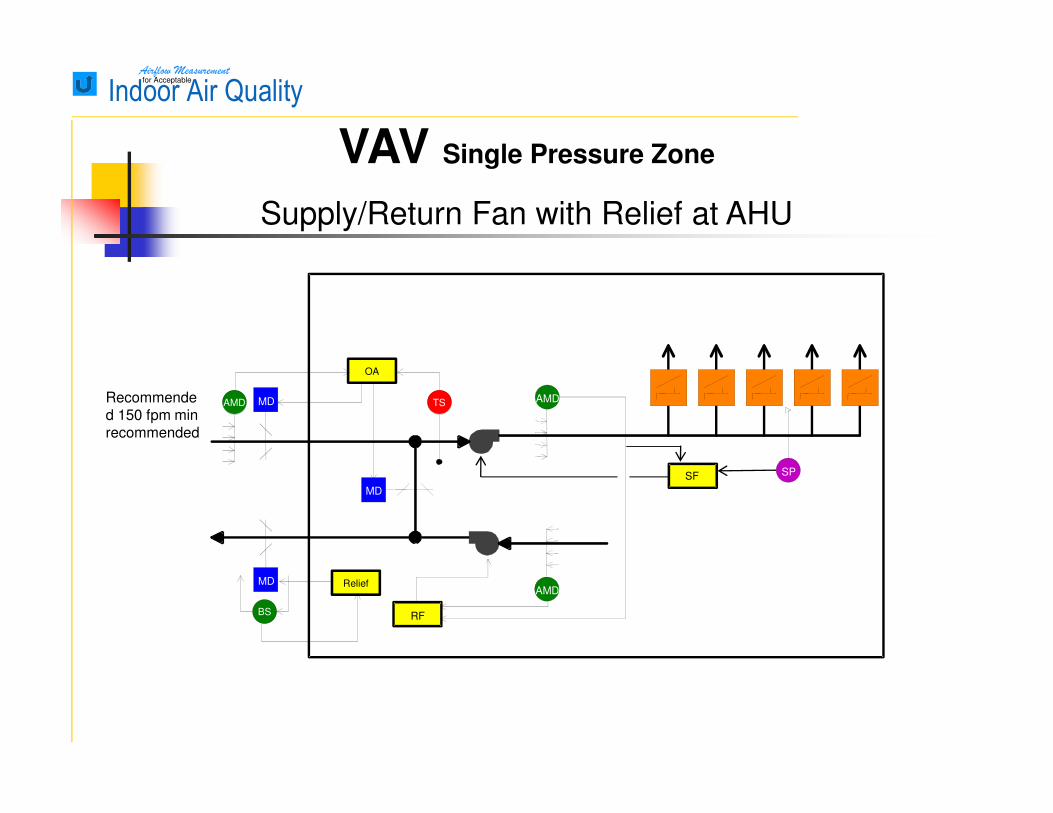
VAV Single Pressure Zone
Supply/Return Fan with Relief at AHU
OA
AMD TSRecommended 150 fpm min recommended
BS
Relief
RF
AMD
AMD
MD
MD
MD
SF SP

Airflow Measurementfor Acceptable
Indoor Air Quality VAV multi-zone pressurization
Supply/Return Fan with Relief at AHU
AMD
AMD
VAV RAtyp.
AMD AMD AMD AMD
AMD AMD AMD AMDRF
SP
150 fpm min
recommended
OA
AMD TS
BS
Relief
Sequence: VAV_SF_RF_Relief_MultiZonePressure
AMD
AMD
MD
MD
Individual Pressure Zone
MD
SF SP
Airflow Measurementfor Acceptable
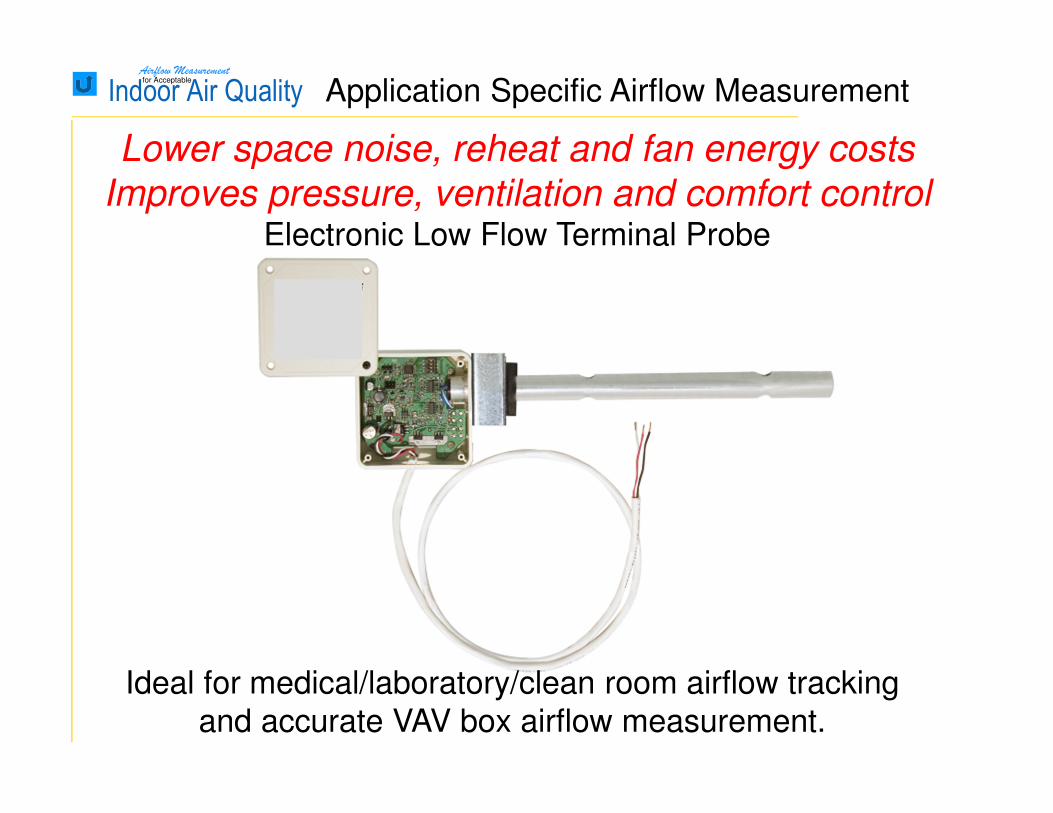
Indoor Air Quality Application Specific Airflow Measurement
Ideal for medical/laboratory/clean room airflow tracking
and accurate VAV box airflow measurement.
Lower space noise, reheat and fan energy costs
Improves pressure, ventilation and comfort control Electronic Low Flow Terminal Probe