Embed Size (px)
Citation preview
1#
Product Data Sheet Rev 1.0 2016. 12. 26
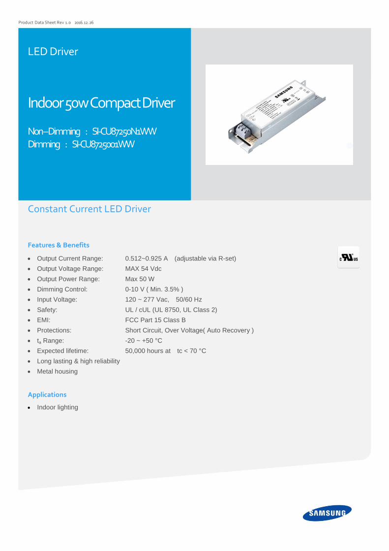
LED Driver
Indoor 50w Compact Driver Non – Dimming : SI-CU87250N1WW Dimming : SI-CU87250o1WW
Constant Current LED Driver Features & Benefits
Output Current Range: 0.512~0.925 A (adjustable via R-set)
Output Voltage Range: MAX 54 Vdc
Output Power Range: Max 50 W
Dimming Control: 0-10 V ( Min. 3.5% )
Input Voltage: 120 ~ 277 Vac, 50/60 Hz
Safety: UL / cUL (UL 8750, UL Class 2)
EMI: FCC Part 15 Class B
Protections: Short Circuit, Over Voltage( Auto Recovery )
ta Range: -20 ~ +50 °C
Expected lifetime: 50,000 hours at tc < 70 °C
Long lasting & high reliability
Metal housing
Applications
Indoor lighting
2
Table of Contents
1. Characteristics ----------------------- 3
2. Typical Characteristics Graphs ----------------------- 5
3. Protection ----------------------- 6
4. Dimming Specification ----------------------- 6
5. Reliability & standard ----------------------- 7
6. Outline Drawing & Dimension ----------------------- 8
7. Label Structure ----------------------- 8
8. Packing Structure ----------------------- 9
9. Precautions in Handling & Use ----------------------- 10

3
1. Characteristics
Article Symbol
Specification
Unit Note
Min. Typ. Max.
INPUT SPECIFICATIONS
Nominal Voltage Vin 120 277 Vac
Voltage Range 108 300 Vac
Nominal Frequency Fin 50 / 60 Hz
Frequency Range 47 63 Hz
Input Current
At 120 Vac Iin 0.56 A At full load
At 277 Vac Iin 0.25 A At full load
Total Harmonic Distortion THD 20 % At 120-277 Vac
Power Factor PF 0.9 - At 120-277 Vac
Efficiency η 87 87
88 89
% At full load, 120 Vac, 60 Hz At full load, 277 Vac, 60 Hz
In-rush Current 30 Apk NEMA410.
OUTPUT SPECIFICATIONS
Voltage Range Vo 37 54 Vdc 70% of MAX power can meet PF,THD
Max. Voltage 60 Vdc Open circuit, No-load protection
Current Range Io 0.512 0.925 A 70% of MAX power can meet PF,THD
Line Regulation -3 3 % @120~277Vac
Load Regulation -5 5 % @120~277Vac, W/O dimming
Current Tolerance -5 5 % @120~277Vac, W/O dimming
Ripple Current 50% % 1
Iavg(Ipeak − Iavg)X100%
Peak current 150% Ipeak
IavgX100%
Nominal Power Po 50 W
Turn-on Delay Time Td 1 s @120Vac, W/O dimmer
1 ) PF, THD, FCC can meet the electrical performance from 70% of MA X power.
2 ) Measured the unit is thermally stabilized after half an hour, Ta 25℃.
4
Article Symbol
Specification
Unit Note
Min. Typ. Max.
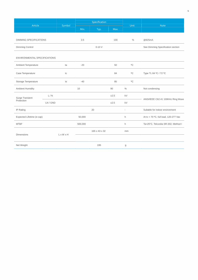
DIMMING SPECIFICATIONS 3.5 100 % @925mA
Dimming Control 0-10 V See Dimming Specification section
ENVIRONMENTAL SPECIFICATIONS
Ambient Temperature ta -20 50 ºC
Case Temperature tc 84 ºC Type TL 84 ºC / 72 ºC
Storage Temperature ts -40 85 ºC
Ambient Humidity 10 90 % Not condensing
Surge Transient Protection
L / N ±2.5 kV
ANSI/IEEE C62.41 100KHz Ring Wave
LN / GND ±2.5 kV
IP Rating 20 - Suitable for indoor environment
Expected Lifetime (e-cap) 50,000 h At tc < 70 ºC, full load, 120-277 Vac
MTBF 500,000 h Ta=25°C, Telcordia SR-332, Method I
Dimensions L x W x H
165 x 43 x 32 mm
Net Weight 195 g
5
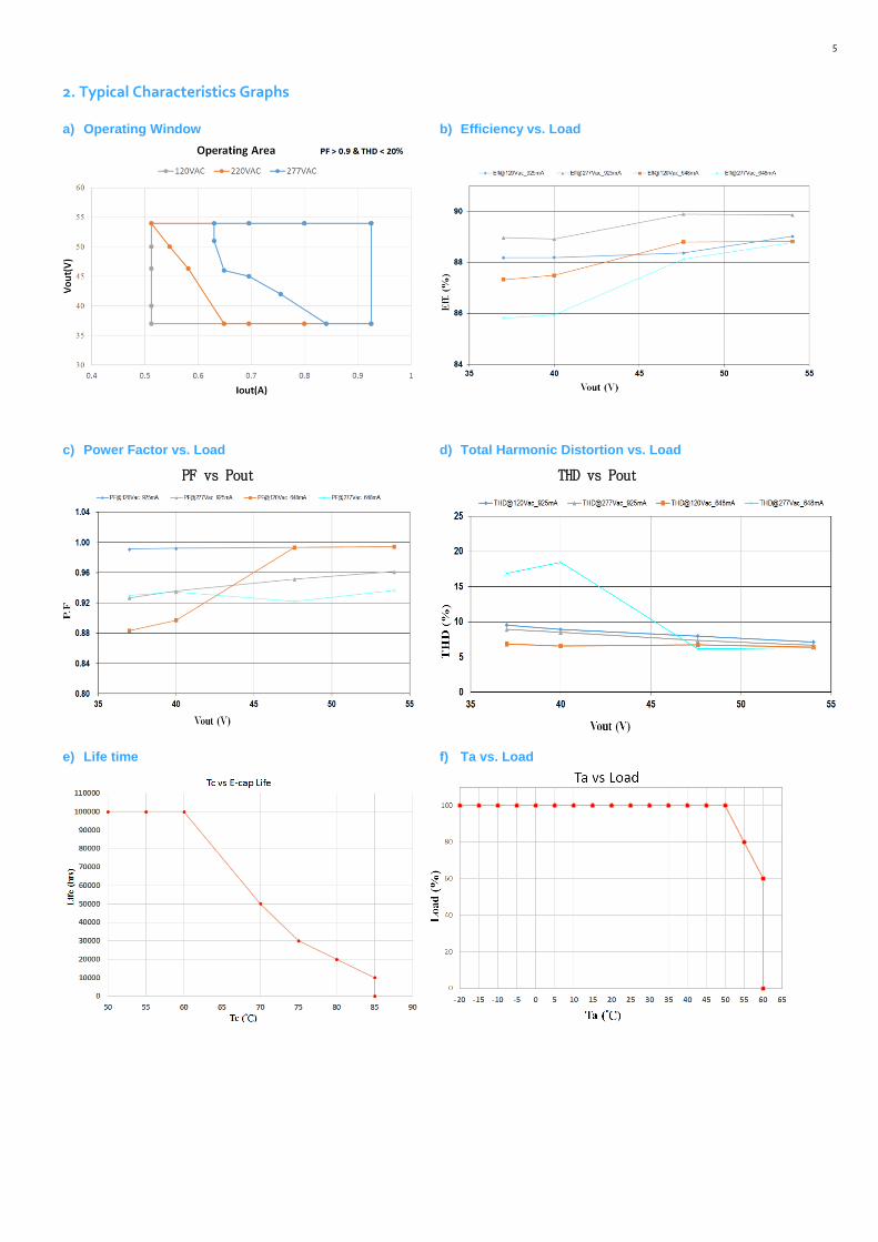
2. Typical Characteristics Graphs a) Operating Window b) Efficiency vs. Load
c) Power Factor vs. Load d) Total Harmonic Distortion vs. Load
PF vs Pout THD vs Pout
e) Life time f) Ta vs. Load
6
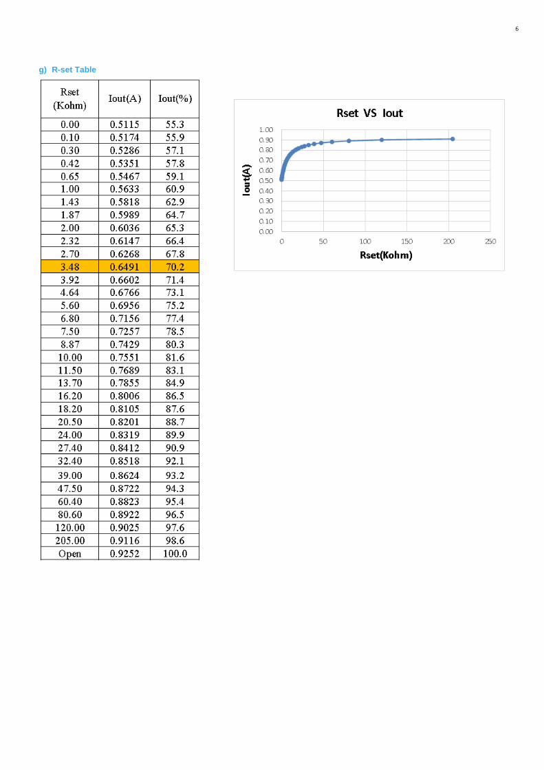
g) R-set Table
7
3. Protection
a) Output Short Circuit Protection
The unit is protected when output is short thus avoiding safety hazard, shock hazard and damage to the unit.
After the short circuit fault condition is removed, the unit will enter the auto-recovery mode.
b) Output Over Voltage Protection
When no load condition occurs, the unit will clamp output voltage to the OVP Voltage avoiding damage to the unit.
After the load is connected, the unit will enter the auto-recovery mode.
The OVP Voltage varies according to the Rset resistor value (see below curve and table) and under 60 V.
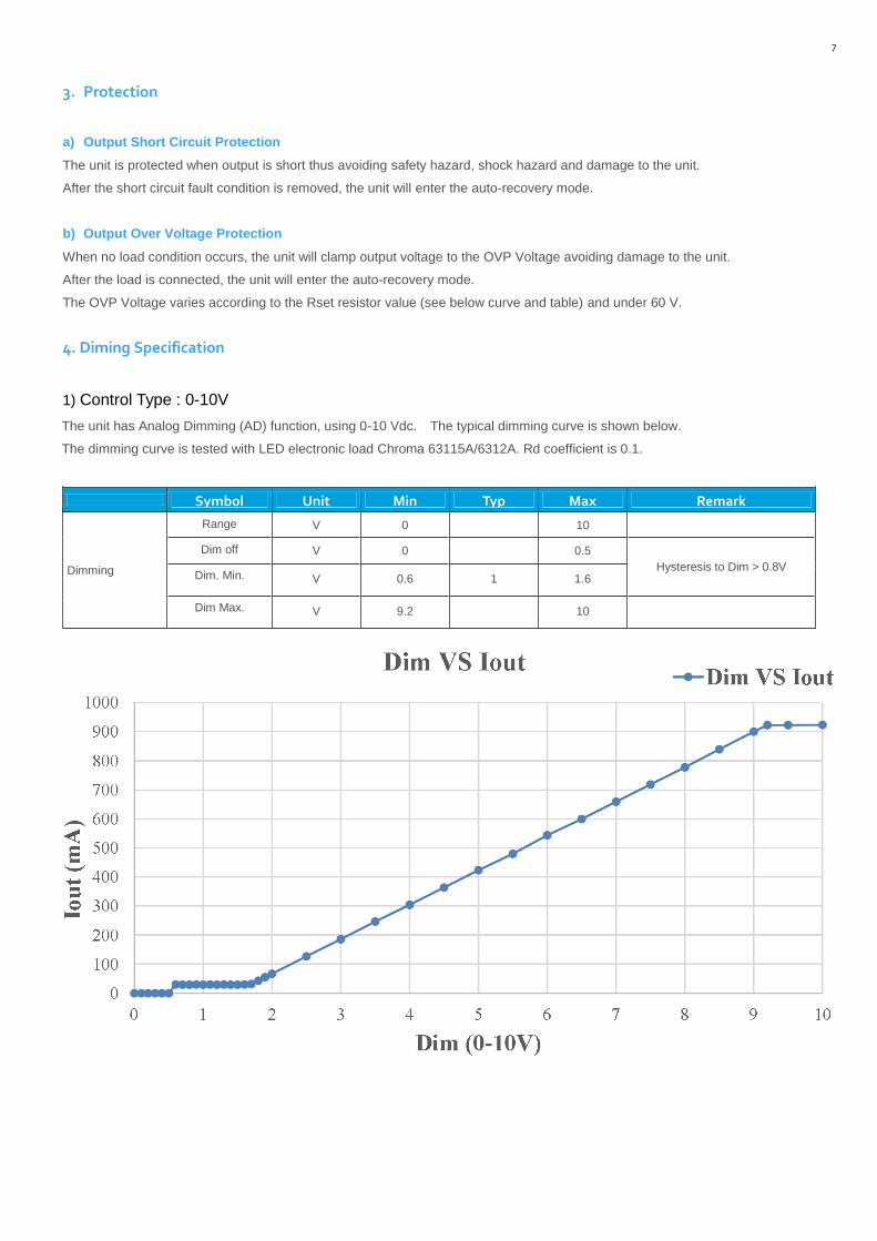
4. Diming Specification
1) Control Type : 0-10V
The unit has Analog Dimming (AD) function, using 0-10 Vdc. The typical dimming curve is shown below.
The dimming curve is tested with LED electronic load Chroma 63115A/6312A. Rd coefficient is 0.1.
Symbol Unit Min Typ Max Remark
Dimming
Range V 0 10
Dim off V 0 0.5
Hysteresis to Dim > 0.8V Dim. Min. V 0.6 1 1.6
Dim Max. V 9.2 10
8
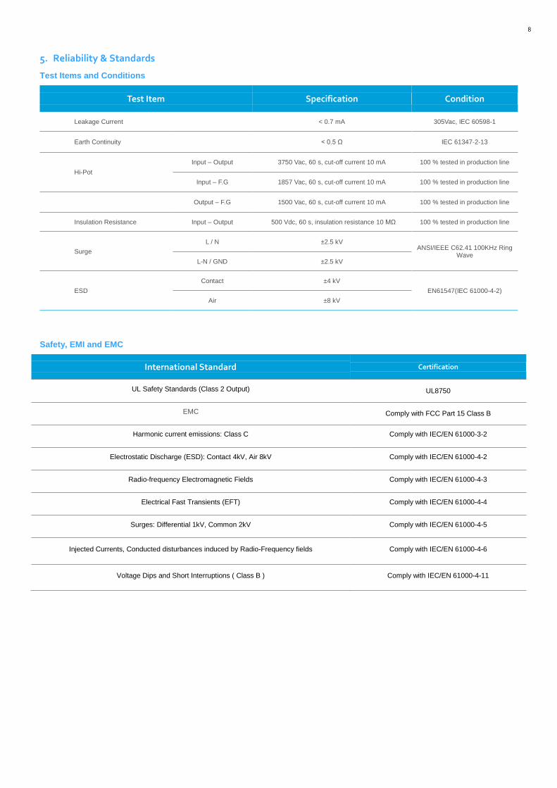
5. Reliability & Standards
Test Items and Conditions
Test Item Specification Condition
Leakage Current < 0.7 mA 305Vac, IEC 60598-1
Earth Continuity < 0.5 Ω IEC 61347-2-13
Hi-Pot
Input – Output 3750 Vac, 60 s, cut-off current 10 mA 100 % tested in production line
Input – F.G 1857 Vac, 60 s, cut-off current 10 mA 100 % tested in production line
Output – F.G 1500 Vac, 60 s, cut-off current 10 mA 100 % tested in production line
Insulation Resistance Input – Output 500 Vdc, 60 s, insulation resistance 10 MΩ 100 % tested in production line
Surge
L / N ±2.5 kV ANSI/IEEE C62.41 100KHz Ring
Wave L-N / GND ±2.5 kV
ESD
Contact ±4 kV
EN61547(IEC 61000-4-2)
Air ±8 kV
Safety, EMI and EMC
International Standard Certification
UL Safety Standards (Class 2 Output) UL8750
EMC Comply with FCC Part 15 Class B
Harmonic current emissions: Class C Comply with IEC/EN 61000-3-2
Electrostatic Discharge (ESD): Contact 4kV, Air 8kV Comply with IEC/EN 61000-4-2
Radio-frequency Electromagnetic Fields Comply with IEC/EN 61000-4-3
Electrical Fast Transients (EFT) Comply with IEC/EN 61000-4-4
Surges: Differential 1kV, Common 2kV Comply with IEC/EN 61000-4-5
Injected Currents, Conducted disturbances induced by Radio-Frequency fields Comply with IEC/EN 61000-4-6
Voltage Dips and Short Interruptions ( Class B ) Comply with IEC/EN 61000-4-11
9
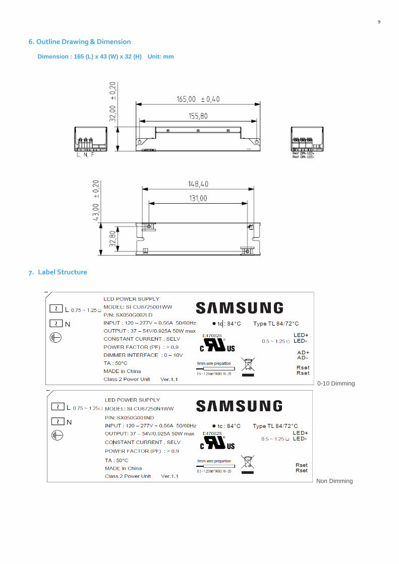
6. Outline Drawing & Dimension
Dimension : 165 (L) x 43 (W) x 32 (H) Unit: mm
7. Label Structure
0-10 Dimming
Non Dimming
10
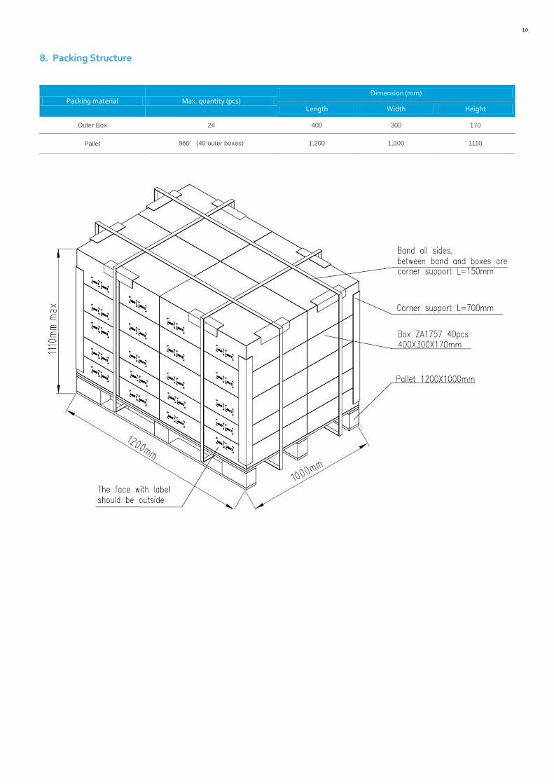
8. Packing Structure
Packing material Max. quantity (pcs) Dimension (mm)
Length Width Height
Outer Box 24 400 300 170
Pallet 960 (40 outer boxes) 1,200 1,000 1110
11
9. Precautions in Handling & Use
1) To prevent the LED Driver from any defect, please handle and store it with care
Do not drop or give shock
Do not store in very humid location or at extreme temperature
Do not open or disassemble the product
2) Static electricity or surge voltage may damage the components inside LED Driver, as such please observe proper anti-
electrostatic working process
People handing the Driver should be well grounded (e.g. using ESD wrist band) and wear anti-static working
clothes and gloves
All related devices and instruments in the production line should be well grounded (e.g. working table, measuring
equipment, assembly jigs)
3) Observe the correct polarity of output terminal
4) Avoid input voltage exceeds the maximum rating, which will cause damage to the circuit and result in malfunction
Legal and additional information.
About Samsung Electronics Co., Ltd.
Samsung Electronics Co., Ltd. inspires the world and shapes the future
with transformative ideas and technologies, redefining the worlds of TVs,
smartphones, wearable devices, tablets, cameras, digital appliances,
printers, medical equipment, network systems and semiconductors.
We are also leading in the Internet of Things space through, among others,
our Digital Health and Smart Home initiatives. We employ 307,000 people
across 84 countries. To discover more, please visit our official website at
www.samsung.com and our official blog at global.samsungtomorrow.com.
Copyright © 2015 Samsung Electronics Co., Ltd. All rights reserved.
Samsung is a registered trademark of Samsung Electronics Co., Ltd.
Specifications and designs are subject to change without notice. Non-metric
weights and measurements are approximate. All data were deemed correct
at time of creation. Samsung is not liable for errors or omissions. All brand,
product, service names and logos are trademarks and/or registered trademarks
of their respective owners and are hereby recognized and acknowledged.
Samsung Electronics Co., Ltd.
95, Samsung 2-ro
Giheung-gu
Yongin-si, Gyeonggi-do, 446-711
KOREA
www.samsungled.com