Embed Size (px)
Citation preview
IS 458:2003
W7mm
Indian Standard
PRECAST CONCRETE PIPES (WITH AND WITHOUTREINFORCEMENT) — SPECIFICATION
(Fourth Revision)
ICS23.040.50;91 .100.30
0 BIS2003
BUREAU OF INDIAN STANDARDSMANAK BHAVAN, 9 BAHADUR SHAH ZAFAR MARG
NEW DELHI 110002
December 2003 Price Group I I
Cement Matrix Products Sectional Committee, CED 53
FOREWORD
This Indian Standard (Fourth Revision) was adopted by the Bureau of Indian Standards, after the draft finalizedby the Cement Matrix Products Sectional Committee had been approved by the Civil Engineering DivisionCouncil.
Precast concrete pipes are widely used for water mains, sewers, culverts and in irrigation. This standard laysdown the requirements of quality and dimensions for concrete pipes to serve as guidance to the manufacturersand users in producing and obtaining concrete pipes of suitable quality. Guidance regarding laying of concretepipes is given in IS 783: 1985 ‘Code of practice for laying of concrete pipes’.
In case liquid conveyed by the pipeline is likely to be harmful to concrete, necessary precautions should betaken.
This standard was first pub] ished in 1956 and subsequently revised in 1961, 1971 and 1988. The present revisionhas been taken up with a view to incorporating the modifications found necessary as a result of experiencegained with the use of this standard. This revision also incorporates some of the important amendments issued tothe last version of the standard including those relating to restricting the use of plain ended pipes and incorporationof detailed provisions regarding pipes manufactured by vibrated casting process and various decisions taken bythe Sectional Committee from time to time.
For the purpose of deciding whether a particular requirement of this standard is complied with, the final value,observed or calculated, expressing the result of a test or analysis, shall be rounded off in accordance with IS 2: 1960‘Rules for rounding off numerical values (revised’. The number of significant places retained in the rounded offvalue should be the same as that of the specified value in this standard.
1S 458:2003
Indian Standard
PRECAST CONCRETE PIPES (WITH AND WITHOUTREINFORCEMENT) — SPECIFICATION
(Fourth Revision)
1 SCOPE
I.1 This standard covers the requirements forreinforced and unreinforced precast cement concretepipes, of both pressure and non-pressure varieties usedfor water mains, sewers, culverts and irrigation. Therequirements for collars are also covered by thisstandard.
NOTES
1 This standard covers the requirements Ior pressure trod
non-pressure pipes manufactured by spinning process andalso non-pressure pipes of class NP3 and NP4 manufactured
by vibrated casting process.
2 [n addition to the requirements specitied specifically forthe collars, the requirements given in the following clauses
shall also apply for the collars:
5.2, s.3, 5.4, 5.5.1, 5.5.3, 5.5.4, 5.7, 5.8, 7.1, 7.2, 7.2.1,7+2.z, 7.3, 7.3,1, 7.4, 8.2, 9.1, 9.1.1, 9.1.2, 9.1.3, 9.1.4,
12.1 and 12.1.1.
1.2 Prestressed concrete pipes and pipes with non-circular section are not covered by this standard.
2 REFERENCES
The standards given in Annex A contain provisionswhich through reference in this text constituteprovisions of this standard. At the time of publication,the editions indicated were valid. Ail standards aresubject to revision and parties to agreements based onthis standard are encouraged to investigate thepossibility of applying the most recent editions of thestandards indicated in Annex A.
3TERMINOLOGY
3.0 For the purpose of this standard, the followingdefinitions shall apply.
3.1 Working Pressure — The maximum sustainedinternal pressure excluding surge, to which each portionof the pipeline may be subjected when installed.
3.2 Site Test Pressure — 1.5 times working pressurepertaining to the section or 1.1 times static pressure,whichever is more (surge pressure is to be controlledwithin 25 percent of pump head in case of pumpingmains).
3.3 Hydrostatic Test Pressure — It is the maximumpressure which the pipe can withstand without anyleakage when tested for hydrostatic pressure inaccordance with this standard and IS 3597.
3.4 Surge (Water Hammer) Pressure — It is a pressurewhich is produced by a change of velocity of tbemoving stream and becomes maximum when there is asudden stoppage which may be caused by the closingof a valve or by shutting down a pump station. Surgepressure is to be controlled within 25 percent of pumphead.
4 CLASSIFICATION
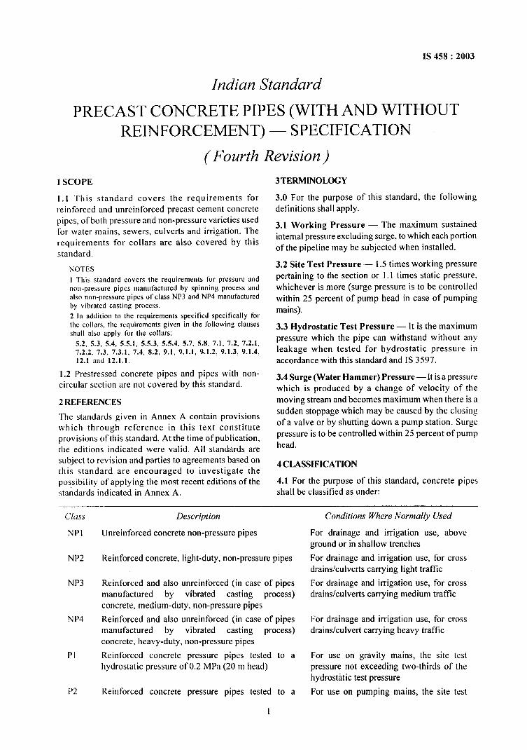
4.1 For the purpose of this standard, concrete pipesshall be classified as under:
Class
NP1
NP2
NP3
NP4
PI
P2
Description
Unreinforced concrete non-pressure pipes
Reinforced concrete, light-duty, non-pressure pipes
Reinforced and also unreinforced (in case of pipesmanufactured by vibrated casting process)concrete, medium-duty, non-pressure pipes
Reinforced and also unreinforced (in case of pipesmanufactured by vibrated casting process)concrete, heavy-duty, non-pressure pipes
Reinforced concrete pressure pipes tested to ahydrostatic pressure of 0.2 MPa (20 m head)
Reinforced concrete pressure pipes tested to a
I
Conditions Where Normally Used
For drainage and irrigation use, aboveground or in shallow trenches
For drainage and irrigation use, for crossdrains/culverts carrying light traffic
For drainage and irrigation use, for crossdrains/culverts carrying medium traffic
For drainage and irrigation use, for crossdrains/culvert carrying heavy traffic
For use on gravity mains, the site testpressure not exceeding two-thirds of thehydrostatic test pressure
For use on pumping mains, the site test
1S 458:2003
<’lass Description Conditions Where Normally Used
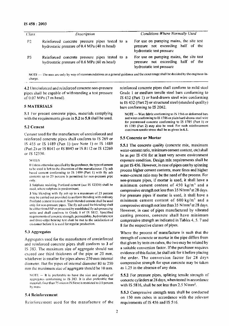
P2
P3
NOTE -
charge.
Reinforced concrete pressure pipes tested to a For use on pumping mains, the site testhydrostatic pressure of 0.4 MPa (40 m head) pressure not exceeding half of the
hydrostatic test pressure
Reinforced concrete pressure pipes tested to a For use on pumping mains, the site testhydrostatic pressure of 0.6 MPa (60 m head) pressure not exceeding half of the
hydrostatic test pressure
Theuses arc only by way of recommendations as a general guidance and the exact usage shall be decided by the engineer-in-
4.2 Unreinforced and reinforced concrete non-pressurepipes shall be capable of withstanding a test pressureof O.07 MPa (7 m head).
5 MATERIALS
5.1 For precast concrete pipes, materials complyktg
with the requirements given in 5.2 to 5.8 shall be used.
5.2 Cement
Cement used for the manufacture of unreinforced andreinforced concrete pipes shall conform to 1S 269 or[S 455 or IS 1489 (Part 1) (see Note 1) or IS 1489(Part 2)or IS 8041 or 1S 8043 orlS 81120rlS 12269or IS 12330.
NO’I’I:S
1 Unless otherwise specified by the purchaser, the type of cementto be wed is Iefi to the discretion of the manufacturer. Fly ash
Imrscd cement conforming to ]S 1489 (Part 1) with il y ash
contents up to 25 percent is permitted t’or non-pressure pipe
only.
2 Sulph:tte resisting Portland cement (see IS 12330) shall be
used, where sulpbatc is predominant.
3 Site blending with Ily fish up to a maximum of 25 percent
miiy be carried out provided its uniform blending with ordinary
Portland cement is ensured. Such blended cement shall be used
only For non-pressure pipes. “1’hefly ash used for blending shall
bc either from ESP or processed by established Ily ash processing
units :ind shall conform to Grade I of IS 3812. Specifiedrequirements ofconcrctc strength, permeability, hydrostatic test
and three-edge bearing test shall be met to the satisfaction of
customer before it is oscd for regular production.
5.3 Aggregates
Aggregates used for the manufacture of unreinforcedand reinforced concrete pipes shall conform to 3 of1S 383. The maximum size of aggregate should notexceed one third thickness of the pipe or 20 mm,whichever is smaller for pipes above 250 mm internaldiameter. Bttt for pipes of internal diameter 80 to 250mm the maximum size of aggregate should be 10 mm.
NOTE — It is preferable to have the size and grading of
aggregates conforming to IS 383. It is also preferable that
nuucrials liocr than 75 micron IS Sieve is restricted to 3.0 percent
hy mass
5.4 Reinforcement
Reinforcement used for the manufacture of the
reinforced concrete pipes shall conform to mild steelGrade 1 or medium tensile steel bars conforming toIS 432 (Part 1) or hard-drawn steel wire conformingto IS 432 (Part 2) or structural steel (standard quality)bars conforming to IS 2062.
NOTE — Wire fabric conforming to IS 1566 or deformed bars
and wires conforming to IS 1786 or plain hard-drawn steel wire
for prestressed concrete conforming to IS 1785 (Part 1) or
IS 1785 (Part 2) may also be used. For such reinforcement
maximum tensile stress shall be as given in 6.1.
5.5 Concrete or Mortar
5.5.1 The concrete quality (concrete mix, maximumwater-cement ratio, minimum cement content, etc) shall
be as per IS 456 for at least very severe environmentexposure condition. Design mix requirements shall be
as per IS 456. However, in case of pipes cast by spinningprocess higher cement contents, more fines and higher
water-cement ratio may be the need of the process. Fornon-pressure pipes, if mortar is used, it shall have a
minimum cement content of 450 kg/m3 and acompressive strength not less than 35 N/mm2 at 28 days.For pressure pipes if mortar is used, it shall have aminimum cement content of 600 kg/m3 and acompressive strength not less than 35 N/mmz at 28 days.However, in case of pipes manufactured by vibratedcasting process, concrete shall have minimumcompressive strength as indicated in Tables 4, 5, 7 and8 for the respective classes of pipes.
Where the process of manufacture is such that thestrength of concrete or mortar in the pipe differs fromthat given by tests on cubes, the two maybe related bya suitable conversion factor. If the purchaser requiresevidence of this factor, he shall ask for it before placingthe order. The conversion factor for 28 dayscompressive strength for spun concrete may be takenas 1.25 in the absence of any data.
5.5.2 For pressure pipes, splitting tensile strength ofconcrete cylinders at 28 days, when tested in accordancewith IS 5816, shall be not less than 2.5 N/mm2.
5.5.3 Compressive strength tests shall be conductedon 150 mm cubes in accordance with the relevantrequirements of IS 456 and IS 516.
2
1S 458:2003
5.5.4 The manufacturer shall give a certificateindicating thequantity ofcernent inthe concrete mix.
5.6 Rubber Ring
Rubber ring chords used in pipe joints shall conformto Type 2 of IS 5382.
5.7 Water
Water used for mixing of concrete and curing of pipesshall conform to 5.4 of IS 456.
5.8 Chemical Admixtures
The admixtures, where used, shall conform toIS9103.
6 DESIGN
6.1 General
Reinforced concrete pipes either spun or vibrated castshall be designed such that the maximum tensile stressin the circumferential steel due to specified hydrostatictest pressure does not exceed the limit of 125 N/mmzin the case of mild steel rods, 140 N/mmz in the caseof hard-drawn steel wires and high strength deformedsteel bars and wires.
6.1.1 The barrel thickness shall be such that under thespecified hydrostatic test pressure, the maximumtensile stress in concrete, when considered as effectiveto take stress along with the tensile reinforcement, shallnot exceed 2 N/mmz for pressure pipes and 1.5 N/mm2for non-pressure pipes. But the barrel wall thicknessshall be not less than those given in Tables 1, 2, 3, 6,9, 10 and I 1 subject to 8.2(iii) for pipes manufacturedby spun process. For pipes manufactured by vibratedcasting process, the barrel wall thickness shall be asgiven ill “]’ables 4, 5, 7 and 8.
6.1.2 Pipes of length above 3 m and up to 4 m maybesupplied by agreement between the user and thesupplier and for such pipes, the quantity ofreinforcement shall be modified as per 6.1.2.1.
6.1.2.1 Longitudinal reinforcement
Reinforced cement concrete pipes of lengths up to4 m maybe accepted if the longitudinal reinforcementis increased in proportion to the square of lengthcompared with what is used for 3 m length as specifiedin Tables 2 to I 1, except for Table 4 and 7.
For ‘L’ (in metre) length of pipe, longitudinalreinforcement shall be L2/3z times the longitudinalreinforcement used for 3 m long pipes.
6.1.3 Longitudinal reinforcement shall be provided toensure rigidity and correct location of cages (grids)longitudinally and to limit the effects of transversecracking, Minimum longitudinal reinforcement shallbe as given in Tables 2, 3, 6, 9, 10 and 11 for pipes
manufactured by spinning process. For reinforcedpipes manufactured by vibrated casting process, theminimum longitudinal reinforcement shall be as givenin Tables 5 and 8.
6.2 Reinforcement
The reinforcement in the reinforced concrete pipe shallextend throughout the length of the pipe and shall beso designed that it may be readily placed andmaintained to designed shape and in the proper positionwithin the pipe mould during the manufacturingprocess. The circumferential and longitudinalreinforcement shall be adequate to satisfy therequirements specified under 6.1.
For non-welded cages spiral reinforcement of the samediameter shall be closely spaced at the end of the pipefor a length of 150 mm to minimize damage duringhandling. The spacing of such end spirals shall notexceed 50 mm or half the pitch whichever is less. Suchspiral reinforcement at ends shall be part of the totalspiral reinforcement specified in different tables.
6.2.1 The pitch of circumferential reinforcement shallbe not more than the following:
a) 200 mm for pipes of nominal internaldiameter 80 to 150 mm,
b) 150 mm for pipes of nominal internaldiameter 200 to 350 mm, and
c) 100 mm for pipes of nominal internaldiameter 400 mm and above.
The pitch shall also be not less than the maximum sizeof aggregate plus the diameter of the reinforcementbar used.
6.2.2 The quantity and disposition of steel in pipes maybe decided by mutual agreement between the purchaserand the supplier; however, it shall be proved bycalculations and tests that the quantity of thereinforcements conforms to all the requirementsspecified in the standard. In the absence of calculationsand tests, the reinforcement given in Tables 2, 3, 6, 9,10 and 11 for pipes manufactured by spinning processand in Tables 5 and 8 for pipes manufactured byvibrated casting process shall be used as minimumreinforcement subject to the requirements of 6.2.2.1.
6.2.2.1 Tolerances given in IS 432 (Part 1), 1S 432(Part 2), and IS 2062 shall be applied to the minimummass of longitudinal reinforcement specified indifferent tables. Total mass of longitudinalreinforcement shall be calculated taking into accountthe clear cover provided at each end of the pipe.
NOTE — For longitudinal reinforcement conforming to IS 432
(Part 2), tolerance on mass shall be calculated from the diameter
tolerance.
6.2.3 If so required by the purchaser, the manufacturershall give a certificate indicating the details relating to
3

1S 458:2003
quality, quantity and dispersion of steel in the pipes aswell as the clear cover to the steel provided in the pipes.
6.3 Ends of Pipes
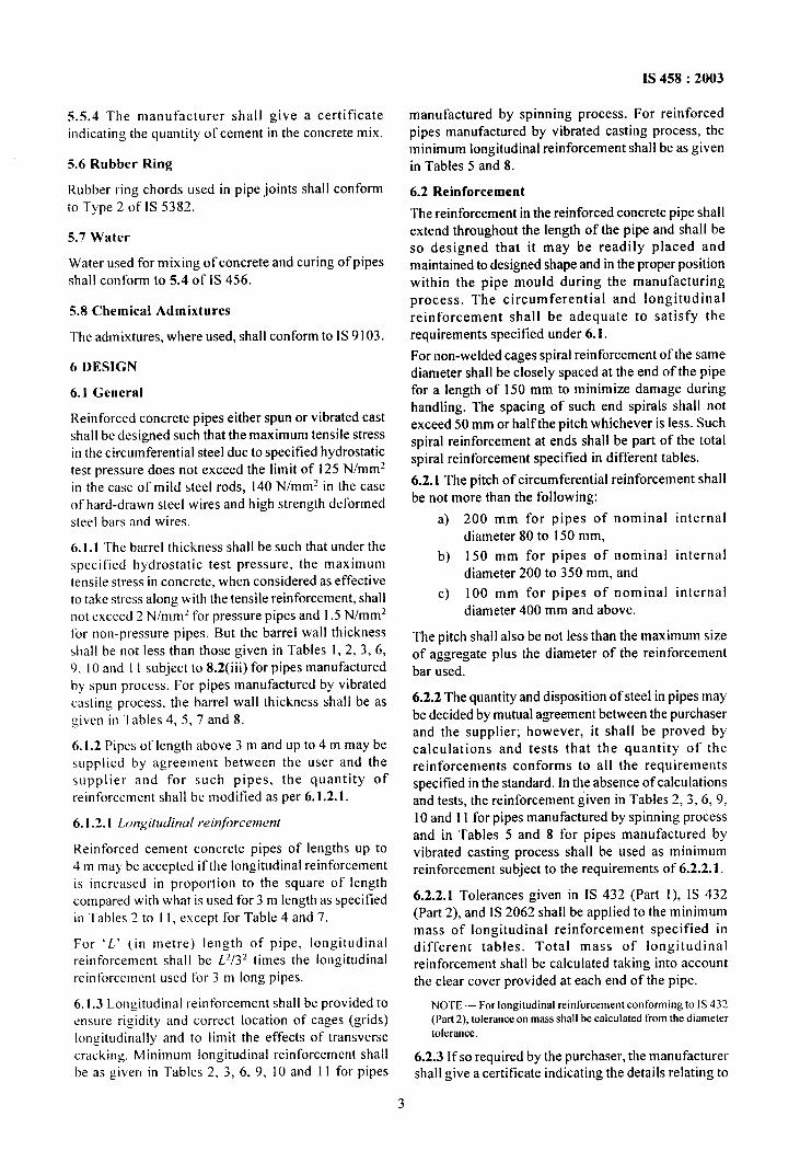
Spigot and Socket ended pipes shall beused for watermains, sewer, irrigation and cuIverts/cross drains.Whereas, flush jointed (NP3 and NP4) and collar jointed(NP2) pipes shall be used for culverts/cross drains only.The ends of concrete pipes used for water mains, sewerand irrigation shall be suitable for socket and spigot, rollon joints or confined gasket joints. Dimensions of spigotand socket for various classes of pipes shall be as givenin Tables 12, 13, 14, 17, 18 and 19 for pipes manufactured
LENGTH OF
.,lo-~: “: :. “i.” .,. :;.:4.
min. . . . .; ””.. loma* . “ . ..” ~ >
.-. . ,.:a:. “A . . .’A”
(
L ~ “ i
t. . . ..
“- . .. . a 74. ,’” ..: :min, .f. i.. ..
1..’ .* d. ..;. . . . . - . ..
12 mm o’3ot
CAULKING SPACEJ ‘ j ID
1A Internal Flush Joints
JOINT
by spinning process. However the dimension of spigotand socket shall be as given in Tables 15 and 16 in case
@q
o.3ot CAULKING SPACE (10 mm]
of pipes manufactured by vibrated casting process. ●..aj h?: & ~.’ . ...?{ 0.35 tReinforcement in socket of rubber ring jointed pipes shall .4 . . . !4.; min.,-. .4.be as given in Table 20. However, the ends of concrete . .“ ~ ,:$::’ t
::4. ... ;
pipes used for road cttlverts/ cross drains maybe suitable ::.. ~ ~ .: 10‘+” 0.30 t
for flush (NP3 and NP4) orcollarjoints (NP2) (see Fig. 1 “ .:~ ? 2rnm~.. min.. . .
and 2). For pipes of diameter up to 700 mm, external[lush joint and for diameters above 700 mm, internal flushjoint is recommended. Dimensions of collars for NP1 IDand NP2 class pipes shall be according to details given inTable 1 and Table21 respectively. The reinforcement in
1B External Flush Joints
collars shall be as given in Table 21. The end of the collar ~ —wall thickness.reinforcement shall have a full ring at both ends. s – 0.002 of intenal dia or 2 mm, Mirr.
NO’I’I:SID – internal diameter,
I Ikwts,junctions and specials thr concrete pipes coveredundercc – included angle not more than 25° (only for design purpose
not be measured).this standard shall conform to the requirements ot’ IS 7322.
2 SOmc typical arrangcnlcnt of reinforcement in socket are
illustrated in Fig. 3 and Fig. 4.
6.3.1 Only flexible rubber ring joints shall be used forthe joints in (a) all pressure pipes and (b) all non-pressure pipes except when used for road cttlvertslcross drains. The pipe joints shall be capable ofwithstanding the same pressures as the pipe.
Nol E ----The requirements of 6.3.1 does not impl y that the collarshal I also be tested for the test pressure for pipes specified in 4.1,
4.2 a!]d 10.2,
6.4 Cover
The minimum clear covers for reinforcement in pipesand collars shall be as given below:
S1 N(). Precast Concrete Pipe/ MinimumCollar Clear Cover, mm
i) Barrel wall thickness:a) Up to and including 75 mm 8b) Over 75 mm 15
ii) At spigot steps 5iii) At end of Iongitudinals 5
NOIE — An effective means shall be provided for maintaining
the reinforcement in position and for ensuring correct cover
during manufacture of the onit. Spacers for this purpose shall
be ot’rustproof material or ofstcel protected against corrosion.
FIG. 1 DETAILS OF FLUSH JOINTS
CEMENT MORTARCAULKING
~.
PIPE
74
FIG. 2 COLLAR JOINT(RIGID)
7 MANUFACTURE
7.1 General
The method of manufacture shall be such that the formsand dimensions of the finished pipe are accurate withinthe limits specified in this standard. The surfaces andedges of the pipes shall be well defined and true, andtheir ends shall be square with the longitudinal axis.
7.2 Concrete Mixing and Placing
7.2.1 Concrete shall be mixed in a mechanical mixer.Mixing shall be continued until there is a uniform
IS 458:2003
===lE=not dropped freely so as to cause segregation. Theconcrete shall be consolidated by spinning, vibrating,spinning combined with vibrations, or otherappropriate mechanical means.
NOTE — No. of Z bars: Minimum halfthe number oflongitudinals.
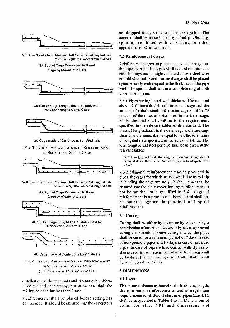
Maximum equal to numbcrot’lorrgitudinals.7.3 Reinforcement Cages
3A Socket Cage Gonnected to BarrelReinforcement cages for pipes shall extend throughout
Cage by Means of Z Bars the pipes barrel. The cages shall consist of spirals orcircular rings and straights of hard-drawn steel wireor mild steel rod. Reinforcement cages shall be placed
r~~ symmetrically with respect to the thickness of the pipe
~= theendsofapipe.
wall. The spirals shall end in a complete ring at both
36 Socket Cage Longitudinal Suitably Bent
for Connecting to Barrel Cage
3C Cage made of Continuous Longitudinal
FIG. 3 TYPICAL ARRANGEMENTS or REINFORCEMENT
IN SOCKET FOR SINGLE CAGE
%l\---?+1---+lNOTE — No. of Z bars: Minimum half the number of Iongitudinals.
Maximum equal to number oflongitudinals.
4A Socket Cage Connected to Barrel
Cage by Means of Z Bars
4B Socket Cage Longitudinal Suitably Bent forConnecting to Barrel Cage
4C Cage made of Continuous Longitudinal
FIG. 4 TYPICAL ARRANGEMENTS OF REINFORCEMENT
IN SocKm FOR DOUBLE CAGE
(USE SUITABLE 1 YPE OF SPACERS)
7.3.1 Pipes having barrel wall thickness 100 mm andabove shall have double reinforcement cage and theamount of spirals steel in the outer cage shall be 75percent of the mass of spiral steel in the inner cage,whilst the total shall conform to the requirementsspecified in the relevant tables of this standard. Themass of longitudinal in the outer cage and inner cageshould be the same, that is equal to half the total massof Iongitudinals specified in the relevant tables. Thetotal longitudinal steel per pipe shall be as given in therelevant tables.
NOTE — It is preferable that single reinforcement cage should
be located near the inner surface of the pipe with adequate clear
cover.
7.3.2 Diagonal reinforcement may be provided in
pipes, the cages for which are not welded so as to helpin binding the cage securely. It shall, however, beensured that the clear cover for any reinforcement isnot below the limits specified in 6.4. Diagonalreinforcement is a process requirement and shall notbe counted against longitudinal and spiralreinforcement.
7.4 Curing
Curing shall be either by steam or by water or by acombination of steam and water, or by use of approvedcuring compounds. If water curing is used, the pipesshall be cured for a minimum period of 7 days in caseof non-pressure pipes and 14 days in case of pressurepipes. In case of pipes where cement with fly ash orslag is used, the minimum period of water curing shallbe 14 days. If steam curing is used, after that it shallbe water cured for 3 days.
8 DIMENSIONS
distribution of the materials and the mass is uniform8.1 Pipes
in colour and consistency, but in no case shall the The internal diameter, barrel wall thickness, length,mixing be done for less than 2 min. the minimum reinforcements and strength test
7.2.2 Concrete shall be placed before setting hasrequirements for different classes of pipes (see 4.1),
commenced. It should be ensured that the concrete kshall be as specified in Tables } to 11. Dimensions ofcollar for class NP1 and dimensions and
5
IS 458:2003
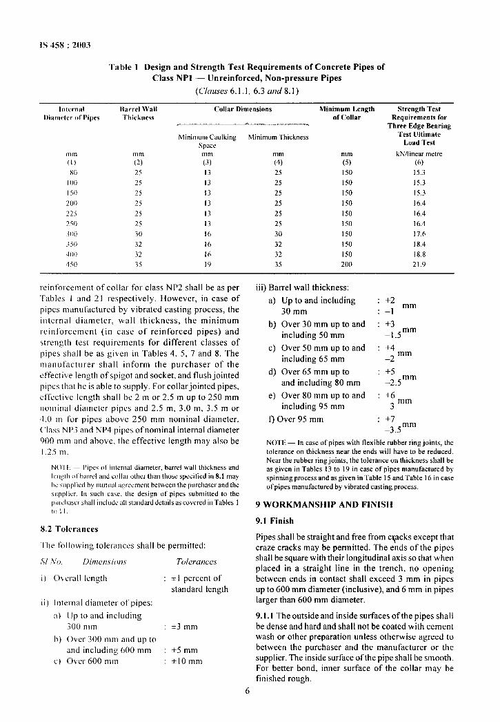
Table 1 Design and Strength Test Requirements of Concrete Pipes ofClass NP1 — Unreinforced, Non-pressure Pipes
(Clauses 6.1.1, 6.3 and 8.1)
Iolcrosrl Ihrrrcl Wall Collar Dimensions Minimum LengthI)iamcter 01 Pipes
Strength Test‘Ihickness of Collar Requirements for
Three Edge Bearing
Minimum Caulking Minimum Thickness Test Ultimate
space Load Test
111Ill nlnl mm mm mm kN/1 inear metre(1) (2) (3) (4) (5) (6)
X() 25 13 25 1S(I 15.3
I 00 25 13 25 1q) 15.3
I 50 25 13 25 150 15.3
200 25 13 25 150 16.4T?$--- 25 13 25 150 16.4
~jo 25 13 25 ] jo 16.4
.;(K) 30 16 30 I 50 17.6
350 32 16 32 I yJ 18.4
‘too 32 16 32 150 18.8
4io 35 19 35 200 21.9
reinforcement of collar for class NP2 shall be as perTables 1 and 21 respectively. However, in case ofpipes manufactured by vibrated casting process, theinternal diameter, wall thickness, the minimumreinforcement (in case of reinforced pipes) andsirenzth test requirements for different classes ofpipes shall be as given in Tables 4, 5, 7 and 8. Themanufacturer shall inform the purchaser of theeffective length of spigot and socket, and flush jointedpipes that he is able to supply. Forcollarjointed pipes,effective length shall be 2 m or 2.5 m up to 250 mmnominal diameter pipes and 2.5 m, 3.0 m, 3.5 m or4,0 m for pipes above 250 mm nominal diameter.Class NP3 and NP4 pipes of nominal internal diameter900 mm and above, the effective length may also be1.25 m.
N()’I I — I)ipcs nt’ inlerntl diameter, barrel wall thickness and
length {~1’barrel and collar other than tbosc spcciticd in 8.1 may
hc suppliut hy mutual a:rccmcnt between tbc purcbascr and the
.uppiicr In such caw. (I1c design crt’pipes submitted to the
purchaser shall include all standard ciclails as covcrcd in “Iables 1
1o11,
8.2 Tolerances
“l-hefollowing tolerances shall be permitted:
,71,%’0. Dit71et7.vi(uz~ Tolerutwes
i) ()~wall length : * i percent of
standard length
ii) internal diameter of pipes:
a) [Jp to and including.3()() mm : +3 mm
h) Over 300 mm and up toand including 600 mm : +5 mm
c) C)ver 600 mm : *lOmm
iii) Barrel wall thickness:
a)
b)
c)
d)
e)
Up to and including30 mm
Over 30 mm up to andincluding 50 mm
Over 50 mm up to andincluding 65 mm
Over 65 mm up toand including 80 mm
Over 80 mm up to andincluding 95 mm
f) Over 95 mm
: +2: –1 ‘m
: +3
–1.5mm
: +4
–2mm
: +5
–2.5mm
: +6
-3 ‘m
: +7_mm
–3.5
NOTE — In case of’ pipes with flexible rubber ring joints, the
tolerance on thickness near the ends will have to be reduced.
Near the robber ring joints, the tolerance on thickness shall be
as given in Tables 13 to 19 in case of pipes manufactured by
spinning process and as given in Table 15 and Table 16 in case
of pipes manufactured by vibrated casting process.
9 WORKMANSHIP AND FINISH
9.1 Finish
Pipes shall be straight and free from clacks except thatcraze cracks may be permitted. The ends of the pipesshall be square with their longitudinal axis so that whenplaced in a straight line in the trench, no openingbetween ends in contact shall exceed 3 mm in pipesup to 600 mm diameter (inclusive), and 6 mm in pipeslarger than 600 mm diameter.
9.1.1 The outside and inside surfaces of the pipes shallbe dense and hard and shall not be coated with cementwash or other preparation unless otherwise agreed tobetween the purchaser and the manufacturer or thesupplier. The inside surface of the pipe shall be smooth.For better bond, inner surface of the collar may befinished rough.
IS 458:2003
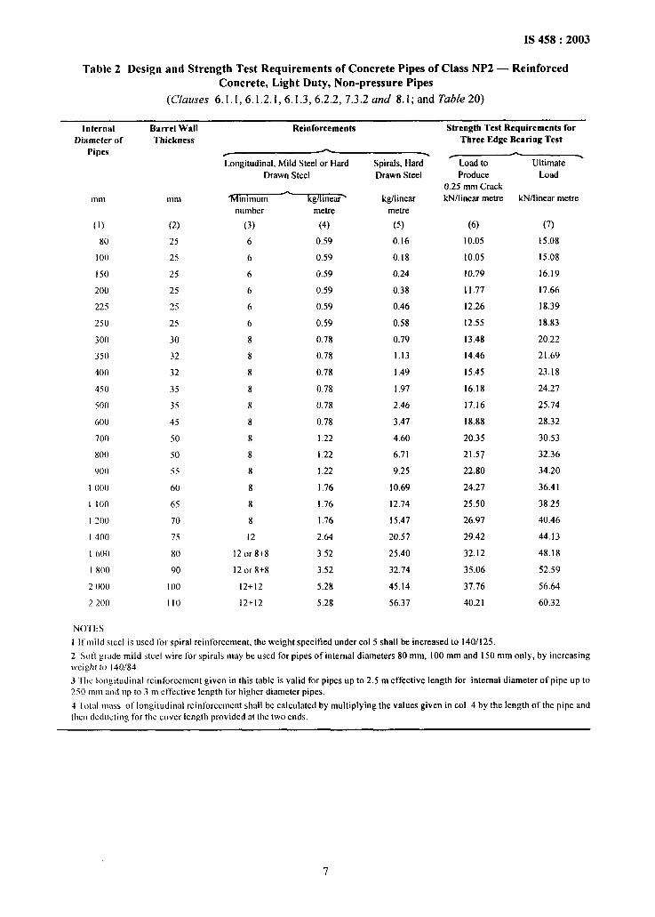
Table 2 Design and Strength Test Requirements of Concrete Pipes of Class NP2 — ReinforcedConcrete, Light Duty, Non-pressure Pipes
(C[auses 6.1.1,6.1.2.1,6.1.3, 6.2.2,7.3.2 and 8.1; and Table 20)
Internal Barrel Wall -... Strength Test Requirements forI)i*meter of Thickness
Pipes
mm mm
(1) (2)
80 25
I 00 25
I 50 25
200 25
225 25
250 25
300 30
350 32
400 32
450 35
500 35
600 45
700 50
800 50
900 55
I ()()0 60
1 100 65
I 200” 70
I 400 75
1 (m 80
1800 90
2 ()()() 100
2200” 110
Longitudinal, Mild Steel or Hard
Drawn Steel
‘Klmlmum kg/1mew>
number metre
(3) (4)
6 0.59
6 0.59
6 0.59
6 0.59
6 0.59
6 0.59
8 0.78
8 0.78
8 0.78
8 0.78
8 0.78
8 0.78
8 I .22
8 1.22
8 I .22
8 1,76
8 1.76
8 1.76
12 2.64
12 or 8+8 3.52
12 or 8+8 3.52
12+12 5.28
12+!2 5.28
Spirals, Hard
Drawn Steel
kg/1inear
metre
(5)
0.16
0.18
0.24
0.38
0.46
0,58
0.79
1.13
1.49
I .97
2,46
3.47
4.60
6.71
9.25
10.69
]2.74
I 5.47
20.57
25.40
32.74
45.14
56.37
Three Edge Bearing Test
~Ultimate
Produce
0.25 mm Crack
kN/linear metre
(6)
10.05
10.05
10.79
11.77
12.26
12.55
13.48
14.46
15.45
16.18
17.16
18.88
20.35
21.57
22,80
24,27
25.50
26.97
29.42
32.12
35.06
37.76
40.21
Load
kN/linear metre
(7)
15.08
15.08
]6.19
17.66
18.39
18.83
20.22
21.69
23.18
24.27
25.74
28.32
30.53
32.36
34.20
36.41
38.25
40.46
44,13
48.18
52.59
56.64
60.32
NO’I’ES
1 It mild steel is used for spiral reint’orcement, the weight specified under COI 5 shall be increased to 140/125.
2 Soil grade mild steel wire for spirals may bc used for pipes of’ internal diameters 80 mm, 100 mm and 150 mm only, by increasing
}veight to 140/84,
3 The longitudinal reinforcement given in this table is valid for pipes up to 2.5 m effective length for internal diameter of pipe up to
250 mm and LIpto 3 m etlcctive length for higher diameter pipes.
4 ‘t’otal mass of longitudinal reinforcement shall be calculated by multiplying the values given in COI 4 by the length olthe pipe and
then dcdocting for the cover length provided at the two ends.
IS 458:2003
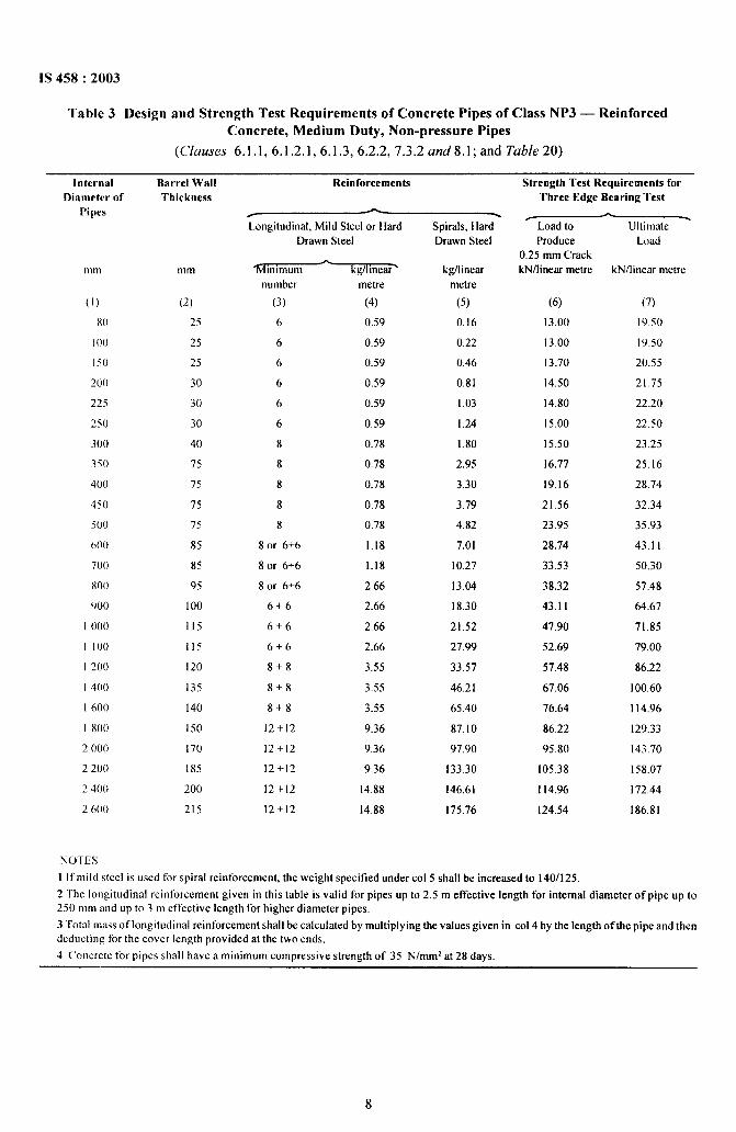
Table 3 Design and Strength Test Requirements of Concrete Pipes of Class NP3 — ReinforcedConcrete, Medium Duty, Non-pressure Pipes
(Clauses 6.1.1,6.1.2.1,6.1.3, 6.2.2,7.3.2 and8.l; and Table 20)
lnternssl Barrel Wall Reinforcements Strength Test Requirements forDiameter of
Pipes
111111
(1)
80
I 00
150
200
225
250
300
350
400
450
500
600
700
w)
900
I 000”
I I 00
I 200
I 400
I 600
I 800
2 ()()()
2200
2400”
2600
Thickness
mm
(2)
25
25
25
30
30
30
40
75
75
75
75
85
85
95
100
115
115
120
135
I 40
150
170
185
200
215
Three Edge Bearing Test
Longitudinal, Mild Steel or Hard
Drawn Steel
‘iWhlmurn kg/i ineai%
number
(3)
6
6
6
6
6
6
8
8
8
8
8
8 or 6+6
8 or 6+6
8 or 6+6
6+6
6+6
rj+(j
8+8
!3+8
8+8
12+12
12+12
12+12
12+[2
12+12
metre
(4)
0.59
0.59
0.59
0.59
0.59
0.59
0.78
0.78
0.78
0.78
0.78
1.18
1.18
2.66
2.66
2.66
2.66
3.55
3.55
3.55
9.36
9.36
9.36
14.88
14.88
Spirals, Hard
Drawn Steel
I@linear
metre
(5)
0.16
0.22
0.46
0.81
1.03
1.24
1,80
2.95
3.30
3.79
4.82
7.01
10.27
13.04
18.30
21.52
27.99
33.57
46.21
65.40
87.10
97.90
133.30
146,61
175.76
Load to Ultimate -
Produce
0.25 mm Crack
kN/linem metre
(6)
13.00
13.00
13.70
14.50
14.80
15.00
15.50
16.77
19.16
21.56
23.95
28.74
33.53
38.32
43,11
47.90
52.69
57.48
67.06
76.64
86.22
95.80
105.38
114.96
124.54
Load
kN/1 inear metre
(7)
19.50
19.50
20.55
21.75
22.20
22.50
23.25
25.16
28.74
32.34
35.93
43.11
50.30
57.48
64.67
71.85
79.00
86.22
100.60
114.96
129.33
143.70
158.07
172.44
186.81
NOTES
I If mild steel is used for spiral reinforcement, the weight specified under COI 5 shall be increased to 140/125,
z ‘Fhc longitudinal reinforcement given in this table is valid for pipes up to 2.5 m effective length for internal diameter of pipe Up to
250 mm and up to 3 m effective length ior higher diameter pipes.
3 Total mass of longitudinal reinforcement shall be calculated by multiplying the values given in COI4 by the length of the pipe and then
deducting for the cover length provided at the two ends,
4 Concrctc for pipes shall have a minimum compressive strength of 35 N/mmz at 28 days.
IS 458:2003
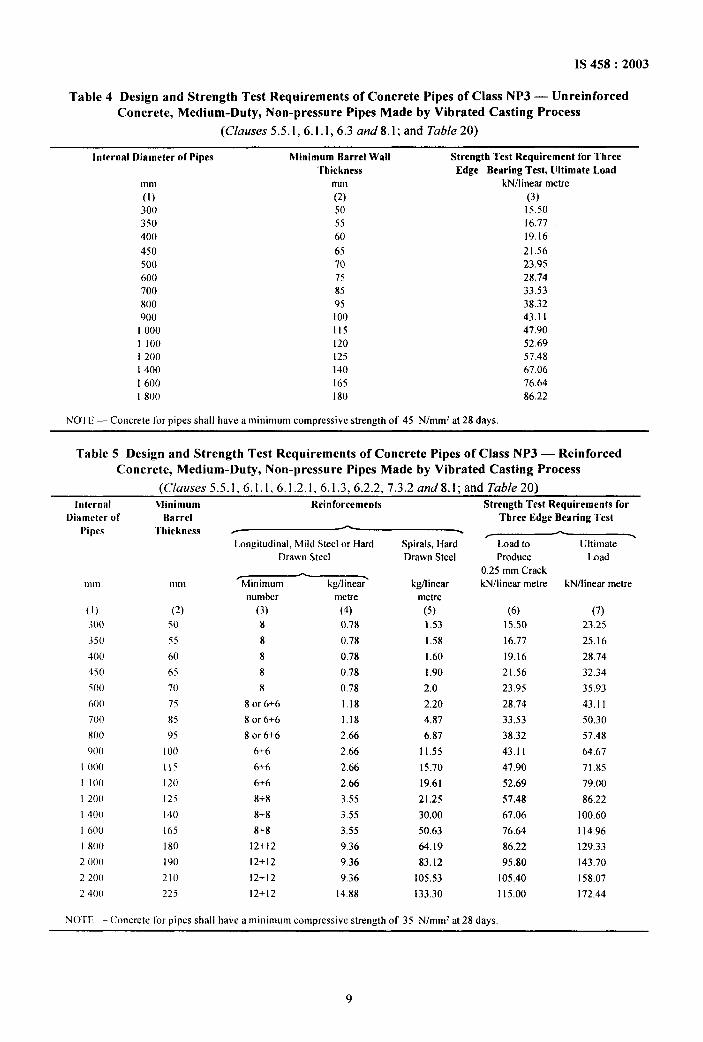
Table 4 Design and Strength Test Requirements of Concrete Pipes of Class NP3 — UnreinforcedConcrete, Medium-Duty, Non-pressure Pipes Made by Vibrated Casting Process
(C/ause.s 5.5.1 ,6.1.1,6.3 and8.l; and Table 20)
Internal Diameter of Pipes Minimum Barrel Wall Strength Test Requirement for Three‘rhiekness Edge Bearing Test, Ultimate Land
mm mm kN/lioear metre
(1) (2) (3)
300 50 15.50
350 55 16.77
400 60 19.16
450 65 21.56
500 70 23.95
600 75 28.74
700 85 33.53
800 95 38.32
900” 100 43.1 I
I 000” 115 47.90
I 100 120 52.69
1200 125 57.48
I 400 140 67.06
1600 165 76.64
1800 180 86.22
NOTE — Concrete Ifw pipes shall have a minimum compressive strength of 45 N/mmz at 28 days.
Table 5 Design and Strength Test Requirements of Concrete Pipes of Class NP3 — ReinforcedConcrete, Medium-Duty, Non-pressure Pipes Made by Vibrated Casting Process
(C/uuses 5.5.1,6.1.1,6.1.2.1, 6.1.3,6 .2.2,7.3.2 and8.l; and Table 20)Internal }Iinimum Reinforcements Strength Test Requirements for
Diameter of Barrel
Pipes Thickness
Longitudinal, Mild Steel or Hard Spirals, Hard
Drawn Steel Drawn Steel
01111 mm
(1) (2)
300 50
350 55
400 60
450 65
500” 70
600 75
700 85
800” 95
900” 100
I ()()() }15
I I 00 120
1200 125
I 400 I 40
1600 165
1800” 180
2 ()()0 I 90
2200” 210
2400” 225
fMinimum
-kg/1inear kgAinear
number metre metre
(3) (4) (5)
8 0.78 1.53
8 0.78 1.58
8 0.78 1.60
8 0.78 I .90
8 0.78 2,0
8 or 6+6 1.18 2.20
8 or 6+6 1.18 4.87
8 or 6+6 2.66 6.87
6+6 2.66 11.55
6+6 2.66 15.70
6+6 2.66 19.61
8+8 3.55 21.25
g+g 3.55 30,00
8+8 3.55 50.63
12+12 9.36 64.19
12+1’2 9.36 83,12
12+12 9.36 105.53
12+12 14.88 133.30
Three Edge Bearing Test
.Load to Ultimate
Produce Load
0.25 mm Crack
kN/iinear metre kN/linear metre
(6)
15.50
16.77
19.16
21.56
23.95
28.74
33.53
38.32
43.11
47,90
52.69
57.48
67.06
76.64
86.22
95.80
105.40
115.00
(7)
23.25
25.16
28,74
32.34
35.93
43.11
50.30
57.48
64.67
71.85
79.00
86.22
100.60
114.96
129,33
143.70
158.07
172.44
NOTE — Concrete Ior pipes shall have a minimum compressive strength of 35 N/mmz at 28 days,
9
1S 458:2003
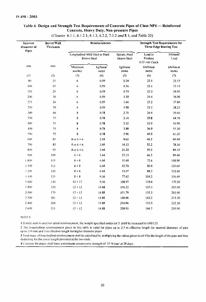
Table 6 Design and Strength Test Requirements of Concrete Pipes of Class NP4 — ReinforcedConcrete, Heavy Duty, Non-pressure Pipes
(Clauses 6.1.1,6.1.2.1,6.1.3, 6.2.2,7.3.2 and8.l; and Table 20)
Internal Barrel WallDiameter of
Pipes
m In
(1)
N)
I00
150
200”
~~j
250
300”
Sio
400
450
500”
600”
700
800
900”
I 000”
I 100
I 200”
I 400
I 600
I 800
2000
2200
2400
2600
NOTES
Thickness
mm
(~)
25
25
25
30
30
30
40
75
75
75
75
85
85
95
I ()()
115
115
120
135
140
150
I 70
185
200”
215
Reinforcements Strength Test Requirements forThree Edge Bearing Test
. - -I,ongitudintri Mild Steel or Hard Spirals, Hard
fLoad to
.Ultimate
Drawn Steel
kg/linear-
metre
(4)
0.59
0.59
0.59
0.59
0.59
0.59
0.78
0.78
0.78
0.78
0.78
2,34
3.44
3.44
3.44
6.04
6.04
6,04
9.36
9.36
14.88
14.88
14,88
14,88
14.88
kg/linear
metre
(5)
0.24
0.36
0.74
1.30
1.64
1.98
2.71
3.14
3.52
3.88
5.96
9.63
14.33
21.20
27.13
35.48
43.76
53.07
77,62
108.97
150.22
151.79
160.90
216.96
258.93
Drawn Steel
0.25 mm Crack
kN/linear
metre
(6)
22.1
22.1
23.3
24.6
25.2
25.5
26,4
29.8
33.9
36,9
40.0
46.3
52.2
59.3
66.3
72.6
80.4
88.3
104.2
119,6
135.3
135.3
142.2
155,0
166.7
Load
kN/linear
metre
(7)
33.15
3315
34.95
36,90
37.80
38.25
39.60
44.70
50.90
55,30
61.20
69.40
78.30
89.10
99,40
108.90
120.60
132.40
156.40
179.50
203,00
203.00
213,30
232,50
250,00
I Ilmild steel is L[sedibr spiral reinforcement, tlw weight specitied under COI 5 shall be increased to 140/125,
2 I hc longitudinal reinlorccrnent given in this table is valid for pipes up to 2.5 m effective length for internal diameter of pipe
LIpto 250 mm and 3 m effective length Ior higher diameter pipes.
3 ‘Iotal mass of’longitudinal reinlorccmen( shall be calculated by multiplying the values given in COI4 by the length of the pipe and then
dedLictIng tor the cover length provided at the two ends.
4 Concrete Ior pipes shall have a minimum compressive strength of 35 N/mmz at 28 days,
10
IS 458:2003
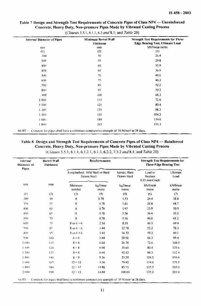
Table 7 Design and Strength Test Requirements of Concrete Pipes of Class NP4 — UnreinforcedConcrete, Heavy Duty, Non-pressure Pipes Made by Vibrated Casting Process
(C/auses 5.5.1,6 .1.1,6.3 and8.l; and Table 20)
Internal Dinmcter of Pipes Minimum Barrel Wall Strength Test Requirements for ThreeThickness Edge Bearing Test, Ultimate Load
mm mm kN/linear metre
(1) (2) (3)
300 50 26.4
350 55 29.8
400 60 33.9
450 65 36.9
500 70 40.0
600 75 46.3
700 85 52.2
800” 95 59.3
9(J() 100 66,3
I 000 115 72.6
i I 00 125 80.4
I 200 135 88.3
1400 155 104.2
I 600” i 80 119.6
1800” 205 135.3
Nofl” -– Concrm ~or pipes shall hwc a minimum compressive strength of 50 N/mrnz at 28 days.
Table 8 Design and Strength Test Requirements of Concrete Pipes of Class NP4 — ReinforcedConcrete, Heavy Duty, Non-pressure Pipes Made by Vibrated Casting Process
(C/uuses 5.5.1,6.1.1,6.1.2.1, 6.1.3,6 .2.2,7.3.2 and 8.1; and Table 20)
Internal . -.. -.. ---- . . .
l)iamcter ot’Pipes
111111
(1)
300”
350
400”
45(}
ioo”
60(1
700
800”
900”
I ()()()
I 100”
I Q()()
I 400
1600”
I 800”
2 O(K)
Barrel Wall
Ulickness
mnl
(2)
50
j!
60
65
70
75
X5
9i
I ()()
IIs
I 20
125
I 40
165
180
I 90
Keintorcements Mrengtn 1est KeqUlreSSSents10r
Three Edge Bearing Test
L.ongitudioal, Mild Steel or Hard Spirals, Hard
Drown Steel Drawn Steel
Minimum
nambcr
(3)
8
8
8
8
8
Xor 6+6
8or 6+6
8or 6+6
6-+6
8+8
8+X
x+x
8+8
12+- 12
12+ 12
12+.12
I@inear
mtre
(4)
078
(),78
(),78
0,78
0.78
2.34
3.44
3,44
3.44
6.04
6.04
6.04
9,36
9.36
14.88
14.88
kgjlinear
metre
(5)
1.53
1.61
1.97
3.36
5.56
8.50
12.78
16.72
20.92
26.70
35.60
42.4?
53,39
79.92
85.75
108.00
Load to
Produce
0.25 mm Crack
kN/lineot
metre
(6)
26.4
29.8
33.9
36.9
40.0
46.3
52.2
59.3
66.3
72.6
80.4
X8.3
104,2
119.6
135.3
135.3
Ultimate-
Load
kN/linear
metre
(7)
38.6
44.7
50.9
55.3
61,2
69.4
78.3
89.1
99.4
108.9
120.6
132.4
156.4
I 79.5
203.0
203.0
N()11 Coocrcte for pipes shall have a minimam comprwsive strength of 35 N/mm’ at 2X days.
11

IS 458:2003
Table 9 Design and Strength Test Requirements of Concrete Pipes of Class PI— Reinforced ConcretePressure Pipes Safe for 0.2 MPa Pressure Test
(C/uuses 6.1.1,6.1.2.1,6.1.3, 6.2.2,6 .3,7.3.2 and 8.1; and Tab/e 20)
[ntcrnal Barrel Wall ReinforcementsDiameter of Thickness / - .
Pipes I.oogitudinal, Mild Steel or Harcl Drawn Steel Spirals, Hard Drawn
mm mm
.Minimum kg/linear
numlwr metre
(1) (2) (3) (4)
80 25 6 0.59
I 00 25 6 0.59
150 25 6 0.59
200 25 6 0,59
225 25 6 ().59
250 25 6 0.59
300 30 8 0.78
350 32 8 0.78
40(I 32 8 0.78
450 35 8 0.78
500 35 8 0.78
600 40 8 0.78
700 40 8 1.22
800 45 8 I .22
900 50 8 1,22
I ()()() 55 8 i.76
1 I 00 60 8 1.76
I 200 65 8 1.76
NC)TES
I Strength requirements for pressure pipes shall be the same as for NP2 class pipes.
2 If mild steel is used for spiral reinforcement, the weight specified under COI 5 shall be increased to 140/125.
Steel
I@linern
metre
(5)
0.16
0.22
0.46
0.79
1.00
1.22
1.75
2.37
3.05
3.86
4.72
6.79
9.15
11,94
15.12
18.64
22.88
26.82
3 %lt grade mild steel wire for spirals may be used for pipes of internal diameters 80 mm, 100 mm and 150 mm only, by increasing
\vcight to 140/84,
4 The longitudinal reinforcement given in this table is valid for pipes up to 2.5 m effective length for internal diameter of pipe up to250 mm and up to 3 m effective length for higher diameter pipes.
5 Total mass of longitudinal reinforcement shall be calculated by multiplying the valoes given in COI4 by the length of the pipe and then
deducting for the cover length provided at the two ends.
12
IS 458:2003
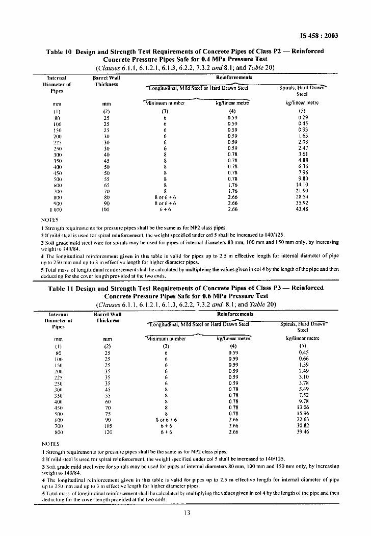
Table 10 Design and Strength Test Requirements of Concrete Pipes of Class P2 — ReinforcedConcrete Pressure Pipes Safe for 0.4 MPa Pressure Test
(C/auses 6.1.1, 6. I.2.1, 6.1.3,6 .2.2,7.3.2 und8.l; and Table 20)
Internal Barrel Wall ReinforcementsDiameter of Thickness —
Pipes longitudinal, M iid Steel or Hard Drawn Steel Spirals, Hard Draw~
Steel— .111111 mm Minimum number kg/linear metre kg/linear metre
(1) (2) (3) (4) (5)
80 25 6 0.59 0.29I 00 25 6 0.59 0.45
150 25 6 0.59 0.93200 30 6 0.59 1.63225 30 6 0.59 2.03,250 30 6 0.59 2,47
300 40 8 0.78 3.61350 45 8 0.78 4.88400 50 8 0.78 6.36450 50 8 0.78 7.96
500 55 8 0.78 9.80600” 65 8 1.76 14.10
700 70 8 1.76 21.90800 80 8or6+6 2.66 28.54900” 90 8or6+6 2.66 35.92
1000 I 00 6+6 2.66 43.48
NorEs
1 Strcn:th requirements Ior pressure pipes shall bc the same as for NP2 class pipes.
2 It’ mild steel is used for spiral reinforcement, the weight specitied under COI 5 shall be increased to 140/125.
3 Soft grade mild steel wire for spirals may be used for pipes of internal diameters 80 mm, 100 mm and 150 mm only, by increasingweight to 140/84.
4 ‘Ihc longitudinal reinforcement given in this table is valid for pipes up to 2.5 m effective length for internal diameter of pipe
up to 250 mm and up to 3 m effective Iengtb Ior higher diameter pipes.
5 T’otal mass of longitudinal reinforcement shall be calculated by multiplying the values given in COI4 by the length of tbe pipe and then
(lcducting for the cover length provided at the two ends.
Table 11 Design and Strength Test Requirements of Concrete Pipes of Class P3 — ReinforcedConcrete Pressure Pipes Safe for 0.6 MPa Pressure Test
(Clauses 6.1.1,6.1.2.1,6.1.3, 6.2.2,7.3.2 and 8.1; and Table 20)
Internal Barrel Wxll ReinforcementsI)iametcr of Thickness -
Pipes ~.ongitudinal, Mild Steel or Hard Drawn Steel Spirals, Hard Draw~Steel
Ill m
(1)
80100I 50200225
250300350400”450500”
600”700800
mm
(2)
252525353535455560707590105120
%linimum number-
kg/linear mew?
(3) (4)
6 0.596 0.596 0.596 0.596 0.596 0.59
8 0.788 0.788 0.788 0.788 0.78
8or6+6 2.666+6 2.666+6 2.66
kg/linear metre
(5)
0.450.661.392.493.103.785.497.529.78
13.06i 5.9622.6330,8239.46
Norm
I Strength requirements for pressure pipes shall be the same as for NP2 class pipes.
2 It’ milcl steel is used for spiral reinforcement, the weight specitied under COI 5 shall be increased to 140/125.
3 Soft grade mild steel wire for spirals may be used for pipes of internal diameters 80 mm, 100 mm and 150 mm only, by increasingweight to 140/84.
4 “tic longitudinal rcinlorccment given in this table is valid for pipes up to 2.5 m effective length for internal diameter of pipeup to 250 mm and up to 3 m effective length for higher diameter pipes.
5 ‘fetal mass of Iongi(odinal reinforcement shall be calculated by multiplying tbe values given in COI4 by the length oftbe pipe and thendeducting for the cover length provided at the two ends.
13
IS 458:2003
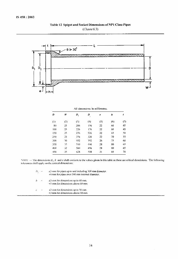
Table 12 Spigot and Socket Dimensions of NP1 Class Pipes
(Clause 6.3)
I ~ 0>30’
T v““’’’’’’’’’’’’’’’’’’’’’’’’’’’’’-’’’’’”’’””’ ‘ 1DI D2 — D
L k ~-””””’”””’”’”’’’”””’”
1
II Tw
All dimensions in millimctres,
D w D, D e h f
(1) (2) (3) (4) (5) (6) (7)
80 25 206 [56 22 60 45
100 25 226 176 22 60 45
I 50 25 276 226 22 65 50
250 25 376 326 22 70 55
300 30 452 392 26 75 60
350 32 ~lo 446 28 80 65
400 32 560 496 28 80 65
450 35 628 558 31 85 70
N()’~l; — “1’hedin]cnsions .02 /7 and e sIMII conlcmn @ the values given in this table as these are critical dimeilsions. The following
(olcronces shall apply 011 the critical dimensions:
D> = *3 mm fir pipes up to and including 300 mm diameter+4 mm for pipes over 300 mm internal diameter.
h = +3 mm for dimensions up to 60 mm.+5 mm for dimensions above 60 mm
e= +2 mm t’or dimensions up to 30 Imm.
+3 mm for dimensions above 3(I mm.
[4
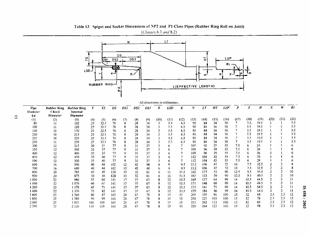
Table 13 Spigot and Socket Dimensions of NP2 and P1 Class Pipes (Rubber Ring Roll on Joint)
[Clauses 6.3 mm’ 8.2)
N LT4 *
g , {-q ‘1-+ ~ , ,, .’ \
DSm1- Dsl DS2 DS3
‘ : m@_+LSD
+ K R m z x Pw
RuBBER RING—L(EFFECTIVE LENGTH)
:
f
Al] dlmen>lons m milllmetres
Pipe
Diameter
w! M(1)
80I 00
150200125
250300350
400450
500600700
800900
1000
1100
1200
I 4001600
1800
2000
2200
Rubber Ring
ChordDiameter
(2)
11II11II1111
1212
121212
1616
2020
2222
2222
25
25
25~~
1 1> LAS
(4) (5) (6)25 32.5 7025 32.5 7025 32.5 7025 32.5 7025 32.5 7025 32.5 7030 35 77
32 37 7732 37 77
35 4(3 77
35 40 7740 44 I 0240 44 I 0245 49 12850 56 12855 60 14160 65 14165 71 14175 82 14180 87 16590 99 165
I 00 I 09 165110 119 165
In 1
(7)
88
88
88
99
999
121215
15
17
1?
17
1?20~()
20
20
LxYL
(8)
2828
2828
2828
3131
31313142
4252
52
5757
57
5767
67
67
67
UA5
(9)
3434
34343-I
343737
3737
3748
48
6161
67
6767
6778
78
78
78
K
(lo)3
3333
333
333
66
66
8
88
88
8
8
8
L.3u
(Ii)5.55,5
5.55.55.55.5
66
666
9
911
111212121215ISIS15
K Iv
(12) (13)6.5 95
6.5 956.5 95
6.5 956,5 956.5 95
7 1077 1097 I097 1127 1129.5 13.29.5 13.2
11.5 16211.5 16513.5 16913.5 17113.5 17313.5 17915 20515 210]S 215Ij 220
LI
(14)848484848484929696
10410410610611713313714816118419522 I
242264
Rubber Ring - ‘“ ‘- ‘-- ‘-- ‘-” “ ‘-- “r “ ‘- HT LSF P S H ‘“ ““” ‘-Internal
Diameter
(3)102120I 70215225250315360400450500590680785875980
1070I 17013701560I 780I 9352130
(15) (16) (17) (18) (19)34 S(I 7 5.5, 19.534 50 7 5.5 19.534 50 7 5,5 19.534 50 7 j.~ 19.534 50 7 5.5 19.534 50 7 5.5 19.537 55 7.5 6 2439 j~ 7.5 6 2639 55 7.5 6 2642 55 7.5 6 2942 55 7.5 6 2947 72 10 7.5 32.547 72 10 7.5 32.552 90 12.5 9.5 35.559 90 12.5 9.5 40.564 99 14 10.5 44.569 99 14 10.5 49.575 99 14 10.5 54.586 99 14 10.5 64.591 100 15 12 68
103 100 15 12 78
113 100 15 88123 I00 15 :; 98
x
(20)11111111I11222222222.52.52.52.5
w K[
(21) (22)1 5.51 5.51 5.51 5.51 5.51 5.5
I 61 61 61 61 628282 102 102 112 112 11 =2 11 A2.5 12 m
m2.5 12 . .2.5 12 N
o2.5 12 0
u
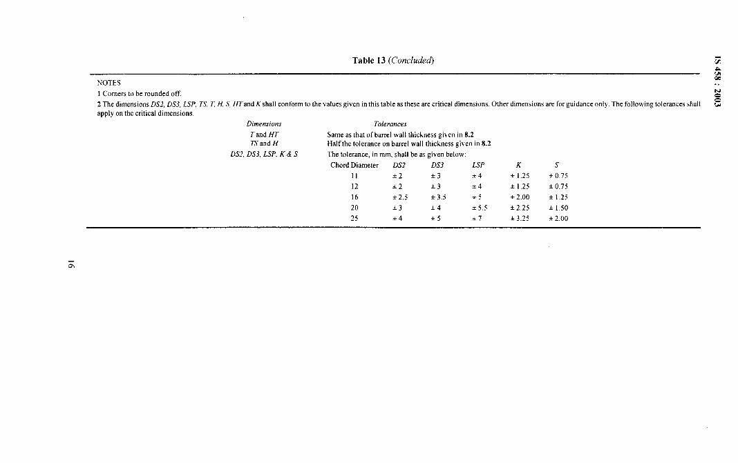
Table 13 (Corrcluded Gam
NOTESw
1 Corners to be rounded off.
. .wo
2 The dimensions DS2, D.S3, LSP, 7S, t H, S, ffTand K shall conform to the values given in this table as these are critical dimensions. Other dimensions are for guidance only. The following tolerances shall
aPPIY on the critical dimensions.
3
Dimensions Tolerarws
T and HT Same as that of barrel wail thickness given in 8.2TS and H Half the tolerance on barrel wall thickness given in 8.2
DS2, DS3, LSP, K&S The tolerance, in mm, shall be as given below:
Chord Diameter DS2 DS3 LSP K s
11 *2 &3 *4 * 1.25 ● 0.75
12 *2 *3 ● 4 k 1.25 * ().75
16 *2.5 *3.5 *5 * 2.00 * 1.25
20 *3 +4 *5.5 *2.25 * 1.50
25 +4 *5 *7 * 3.25 * 2.00

Table 14 Spigot and Socket Dimensions of NP3 and NP4 Class pipes (Rubber Ring Roll on Joint] from 80 to 900 mm Diameter
(Clauses 6.3 and 8.2)
N 1, LT
& , $+!iJ+ ‘~ , ., ; ‘1
0Sm+ S1 0s2 DS 3
LSD‘ ~ .rqq+
1- K R W x x P
RUBBER RING—< L(EFFECTIVE LENGTH)
J
All dimensions in millimetres
Pipe Rubber Ring Rubber Ring T TS DS DSI DS2Diameter
DS3 R LSD N LT HT LSP P S H X W RI
4 Chord InternalDA Diameter Diameter
(1)
80
100
150
200
225
250
300
350
400
450
500
600
700
800
900
(2)
11
11
11
11
11
11
12
16
16
16
16
20
20
20
20
(3) (4) (5)
102 25 32.5
120 25 32.5
170 25 32.5
230 30 38
255 30 38
275 30 38
340 40 51
435 75 75
480 75 75
525 75 75
570 75 75
675 85 85
765 85 85
875 95 95
970 100 100
(6)
70
70
70
83
83
83
90
120
120
120
120
150
150
I 50
150
(7)
8
8
8
11
11
11
12
16
16
16
16
20
20
20
20
(8)
28
28
28
38
38
38
42
56
56
56
56
70
70
70
70
(9)
34
34
34
34
34
34
36
48
48
48
48
60
60
60
60
(lo)3
3
3
5
5
5
6
8
8
8
8
10
10
10
10
(11)
5.5
5.5
5.5
6.5
6.5
6.5
7
10
10
10
10
12
12
12
12
K
(12)
6.5
6.5
6.5
6.5
6.5
6.5
7
10
10
10
10
12
12
12
12
(13)
95
95
95
113
113
113
130
158
158
158
158
193
I 93
197
200
(14)
84
84
84
97
97
97
130
135
135
135
135
I 53
153
171
180
(15) (16)
34 50
34 50
34 50
39.5 50
39.5 50
39.5 50
53 55
78 72
78 72
78 72
78 72
88.5 90
88.5 90
98.5 90
103.5 90
(17)
7
7
7
7
7
7
7.5
10
10
10
10
12
12
12
12
(18) (19)
5.5 19.5
5.5 19,5
5.5 19.5
5.5 24.5
5.5 24.5
5.5 24.5
6 34
8 67
8 67
8 67
8 67
10 75
10 75
10 85
10 90
(20)
1
1
I
1
1
1
1
2
2
2
2
~
2
2
2
(21)
I
1
1
1
1
1
1
2
2
2
2
2
2
2
2
(22)
5.5
5.5
5.5
5.5
5.5
5.5
6
8
8
8
8
10
10 ‘%
10 Amm
10 . .
~ow
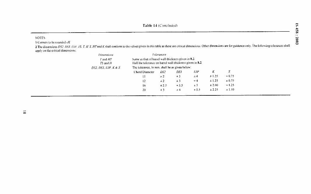
Noms
1 Corners to be roorrded off
2 The dimensions DS2. D.Y.?,LSP 23, 7 H S HTand K shall conform to the values given in this table as these are critical dimensions
apply on the critical dimensions.
Dl!llerrslons TolerancesTand f{T Same as that of barrel wall thickness gik en in 8.2
. .No0
Other dimensions are for guidance only. The following tolerances shallw
TS and 11 Halfthe tolerance on barrel wall thickness given in 8.2
DS2, DS3, LSP, k’& S The tolerance. in mm. shall be as given below:
Chord Diameter DS2 DS3 LSP K s
11 i2 *3 *4 * 1.25 i 0.75
12 *2 *3 *4 * 1.25 * 0,75
16 *2.5 *3.5 *5 * 2.00 * 1.25
20 *3 *4 *5.5 +2.25 * 1.50
00
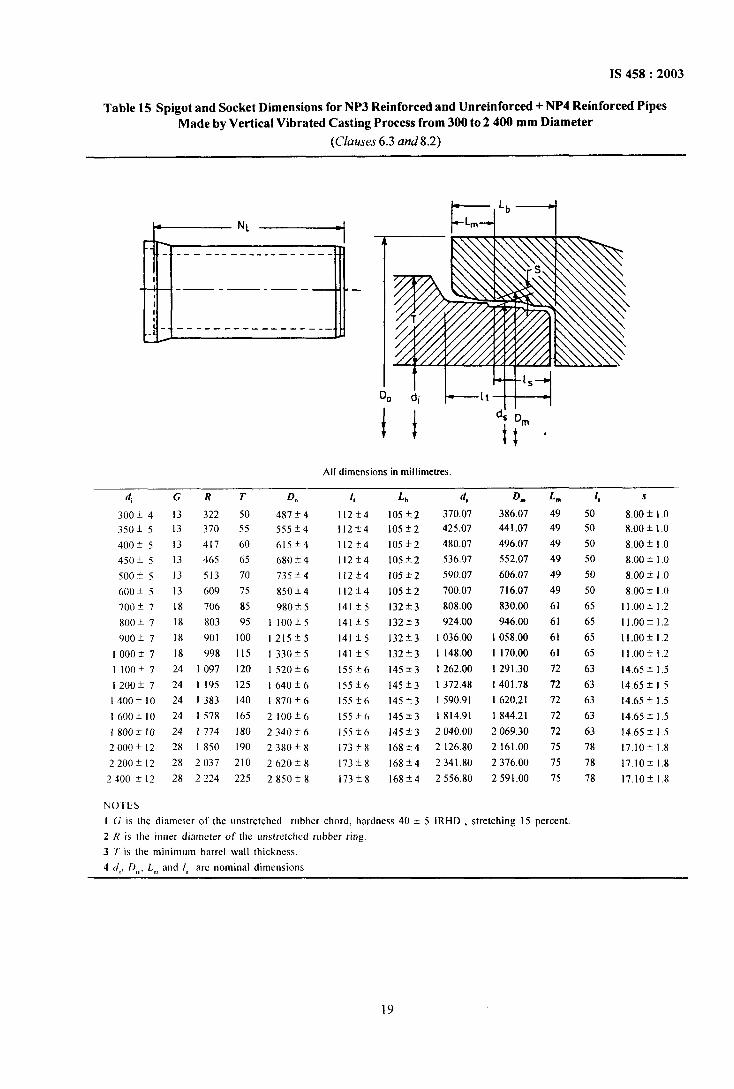
IS 458:2003
Table 15 Spigot and Socket Dimensions for NP3 Reinforced and Unreinforced+ NP4 Reinforced PipesMade by Vertical Vibrated Casting Process from 300 to 2400 mm Diameter
(Clauses 6.3 and8.2)
I--————N’——————+I
-. .- ——-. ------ —---- -
I4 — -—. —. —-
1
11
..L ‘----- —--- ---- ----—
I=+Lbl
t I H-l+
All dimensions in millimetres
(/,
300 t 4
350+ 5
400 * 5
450* 5
500 f 5
600 * 5
700 f 7
800 + 7
900 * 7
1000+7
llooi7
1200+7
1400ilo
1600*10
1800+10
2000* 12
2200f12
2400 *I2
CRT D,,
13 322 50 487 + 4
13 370 55 555*4
13 417 60 615*4
13 465 65 680 + 4
13 513 70 735*4
13 609 75 850 + 4
18 706 85 980 * 5
18 803 95 I 100*5
18 901 100 1215*5
18 998 115 1330f5
24 1097 120 1520~6
24 I 195 125 1640+6
24 I 383 140 1870f6
24 I 578 165 21(JO*6
24 I 774 180 2340 i 6
28 I 850 190 2380*8
28 2037 210 2620*X
28 2224 225 2850*8
1,
112*4
l12f4
l12f4
112+4
l12f4
112*4
141*5
141 *5
141 &5
141 *5
155+6
155*(,
155?6
155*6
155*6
173*8
173*8
173*8
Lb
105*2
105i2
105*2
105*2
105t2
105i2
132f3
132t3
132*3
132*3
145*3
145*3
145*3
14553
145*3
168*4
168*4
168i4
d,
370.07425.07
480.07
536.07
590.07
700.07
808.00
924.00
1036.00
1148.00
I 262.00
1372.48
1590.91
1814.91
2040.00
2126.80
2341.80
2556.80
D.
386.07441.07
496.07
552.07
606.07
716.07
830.00
946.00
I 058.00
1170,00
1291.30
I 401.78
1620,21
1844.21
2069,30
2161.00
2376.00
2591.00
L.
49
49
49
49
49
49
61
61
61
61
72
72
72
72
72
75
75
75
NOTES
I G is Ihe diameter of the unstretched rubber chord, hardness 40 + 5 IRHD , stretching 15 percent
2 R is the inner diameter of the unstretched rubber ring3 T is the minimum barrel wall thickness.
4 d,, D,,,,1.,,,and 1 arc nominal dimensions.
1,
50
50
50
50
50
50
65
65
65
65
63
63
63
63
63
78
78
78
s
8.00 * 1.0
8.00 f 1.0
8.00 ~ I.O
8,00 f 1.0
8.00 f 1.0
8.00 * 1.0
11.00 *1.2
11.oofl.2
11.ooil.2
11,00 *1.2
14.65 * 1.5
14.65 + 1.5
14.65 * 1.5
14.65 * 1.5
14.65 * 1.5
17.10* 1.8
I7.1O* 1.8
17.10* 1.8
19
IS 458:2003
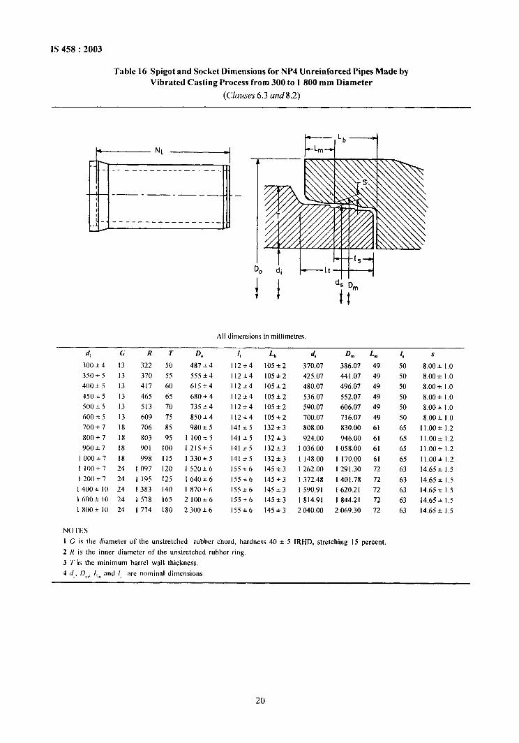
Table 16 Spigot and Socket Dimensions for NP4 Unreinforced Pipes Made byVibrated Casting Process from 300 to 1800 mm Diameter
(Ckw.sw 6.3 amd8.2)
t————— ‘L -1
IF.1-”
I
3t-.—---------_____--—.—.__—-.-—_____________
I=-’bl
T I M--M
All dimensions in millimetres.
IIi G RT D,,
30(I & 4
350+5
400 h 5
450 & 5
500 ● 5
600 * 5
700 * 7
800 ● 7
900 * 7
I 000*7
I IO()+7
1200*7
1 400+ 10
1600+10
1 800+ 10
NOTES
13 322 50 487 + 4
13 370 55 555 + 4
13 417 60 615*4
13 465 65 680 * 4
13 513 70 735 * 4
13 609 75 850 ● 4
]8 706 85 98o + 5
18 803 95 1 100+5
18 90 I 100 1215+5
18 998 115 1330*5
24 I 097 120 1520*6
24 1 195 125 1640*6
24 1383 140 I 870*6
24 I 578 165 2100+6
24 1774 180 2 300+6
[,
112+4
112*4
112+4
112*4
112+4
112*4
141*5
141 *5
141+5
141*5
155*6
155+6
155*6
155*6
155+6
Lb
105+2
105+2
105+2
105+2
105+2
105+2
132*3
132+3
132+3
132+3
145*3
145+3
145+3
145*3
145+3
d,
370.07
425.07
480.07
536.07
590.07
700.07
808.00
924.00
1036.00
1148.00
I 262.00
1372,48
I 590.91
1814.91
2040.00
D.
386.07
441.07
496,07
552.07
606.07
716.07
830.00
946.00
I 058.00
1 170.00
1291.30
I 401.78
1620.21
1844.21
2069.30
L. 1,
49 50
49 50
49 50
49 50
49 50
49 50
61 65
61 65
61 65
61 65
72 63
72 63
72 63
72 63
72 63
s
8.00 * 1.0
8.00 + 1.0
8.00 + 1.0
8.00 + 1.0
8.00 ● 1.0
8.00 + 1.0
11.00*1.2
11,00 +1.2
11.00 *1.2
11.00+ 1.2
14.65 * 1.5
14.65* 1,5
14.65* 1.514.65 * 1.5
14.65* 1.5
I G is the diameter of the unstretched rubber chord, hardness 40 + 5 lRHD, stretching 15 percent.
2 R is the inner diameter of the unstretched rabber ring,
3 T is the minimum barrel wall thickness.
4 d. D,,,, L,,,and [, are nominal dim~nsions.
20
N
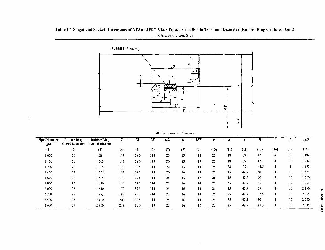
Table 17 Spigot and Socket Dimensions of NP3 and NP4 Class Pipes from 1000 to 2600 mm Diameter (Rubber Ring Confined Joint)
(C/au.~es 6.3 and 8.2)
RUBBER RING>
All dimensionsin millimetres.
Pipe Diameter Rubber Ring Rubber Ring T TS Ls LS1 K LSP u b J H i L gDDA Chord Diameter Internal Diameter
(1) (2) (3) (4) (5) (6) (7) (8) (9) (lo) (Ii) (12) (13) (14) (15) (16)
1000 20 920 115 58.0 114 20 13 114 25 28 39 42 4 9 1102
1100 20 I 003 115 58.0 114 20 13 114 25 28 39 42 4 9 1202
1200 20 1095 120 60.5 [14 20 13 I 14 25 28 39 44.5 4 9 1307
1400 25 1275 135 67.5 114 20 16 114 25 35 42.5 50 4 10 1520
1600 25 1445 140 72.5 114 25 16 114 25 35 42.5 50 4 10 1720
1800 25 1620 150 77.5 114 25 16 114 25 35 42.5 55 4 10 1930
2000 25 I 810 170 87.5 114 25 16 114 25 35 42.5 65 4 10 2150
2200 25 I 995 185 95.0 114 25 16 114 25 35 42.5 72.5E
4 10 2365 A
2400 25 2180 200 102.5 114 25 16W
114 25 35 42.5 80 4 10 2580 00
2600 25 2360 215 110.0. .
114 25 16 114 25 35 42.5 87.5 4 10 2795 NzG
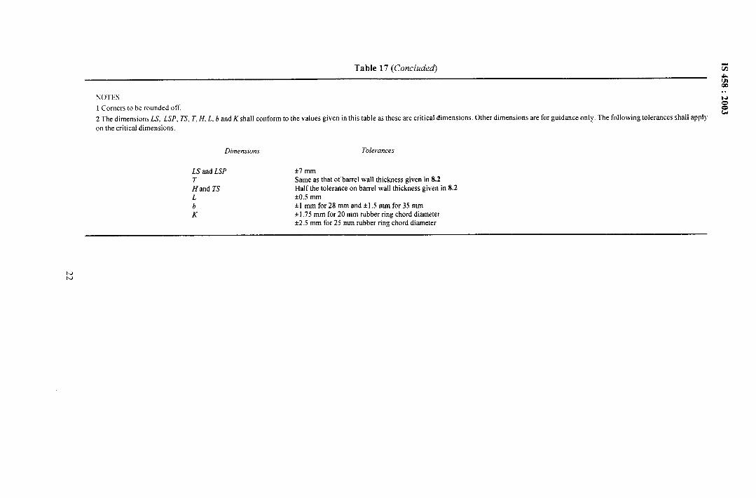
Table 17 (Concluded) G
Rm
NOTES. .
1 Corners to be rounded off.
N
z
2 The dimensions LS. L.SP, 7“, T. H. L. b and K shall conform to the values given in this table as these are critical dimensions. Other dimensions are for guidance only. The following tolerances shall applyw
on the critical dimensions.
Dimensions Tolerances
LSand LSP *7 mm
T Same as that of barrel wall thickness given in 8.2
HandTS Half the toleranee on barrel wall thickness given in 8.2
L *0.5 mm
b +1 mm for 28 mm and +].5 mm for 35 mm
K +1.75mm for 20 mm rubber ring chord diameter+2.5 mm for 25 mm rubber ring chord diameter
IQw
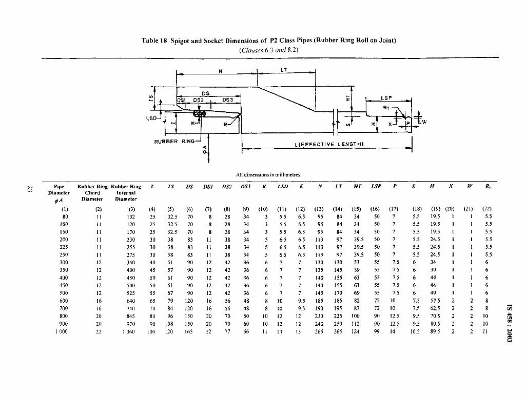
Table 18 Spigot and Socket Dimensions of P2 Class Pipes (Rubber Ring Roll on Joint)
(Clauses 6.3 and 8.2)
11+’, 1+% I:
tt(or
RUBBER RINGJ-2s
I
L(EFFECTIVE LENGTH)
All dimensions in millimetres.
. . ----- . . . . .N ripew
Diameter
+A
(1)
80
100
150
200
225
250
300
350
400
450
500
600
700
800
900
I 000
wtmer rwrg Kuuner iwng
Chord InternalDiameter Diameter
(2) (3)
II 102
11 120
11 170
11 230
11 255
11 275
12 340
12 400
12 450
12 500
12 525
16 640
16 740
20 845
20 970
22 1060
I
(4)
25
25
25
30
30
30
40
45
50
50
55
65
70
80
90
100
TS
(5)
32.5
32.5
32.5
38
38
38
51
57
61
61
67
79
84
96
108
120
DS
(6)
70
70
70
83
83
83
90
90
90
90
90
120
120
150
150
165
----- ---- . . . “..
U.S1
(7)
8
8
8
11
11
11
12
12
12
12
12
16
16
20
20
22
USA
(8)
28
28
28
38
38
38
42
42
42
42
42
56
56
70
70
77
LAM
(9)
34
34
34
34
34
34
36
36
36
36
36
48
48
60
60
66
K I-AU
(lo) (11)
3 5.5
3 5.5
3 5.5
5 6.5
5 6.5
5 6.5
67
67
67
67
67
8 10
8 10
10 12
10 12
11 13
KN
(12) (13)
6.5 95
6.5 95
6.5 95
6.5 113
6.5 113
6.5 113
7 130
7 135
7 140
7 140
7 145
9.5 185
9.5 190
12 230
12 240
13 265
LT HT
(14) (15)
84 34
84 34
84 34
97 39.5
97 39.5
97 39.5
130 53
145 59
155 63
155 63
170 69
185 82
195 87
225 100
250 I 12
265 124
LSP
(16)
50
50
50
50
50
50
55
55
55
55
55
72
72
90
90
99
P
(17)
7
7
7
7
7
7
7.5
7.5
7.5
7.5
7.5
10
10
12.5
12.5
14
s
(18)
5.5
5.5
5.5
5.5
5.5
5.5
6
6
6
6
6
7.5
7.5
9.5
9.5
10.5
19.5
19,5
19.5
24.5
24.5
24.5
34
39
44
44
49
57.5
62.5
70.5
80.5
89.5
1
1
1
1
1
1
1
I
1
1
1
2
2
2
2
2
w R,
(21) (22)
1 5.5
1 5.5
1 5.5
1 5.5
1 5.5
I 5.5
16
16
16
16
16
28
28 %
2 10 f%
2m
10 . .
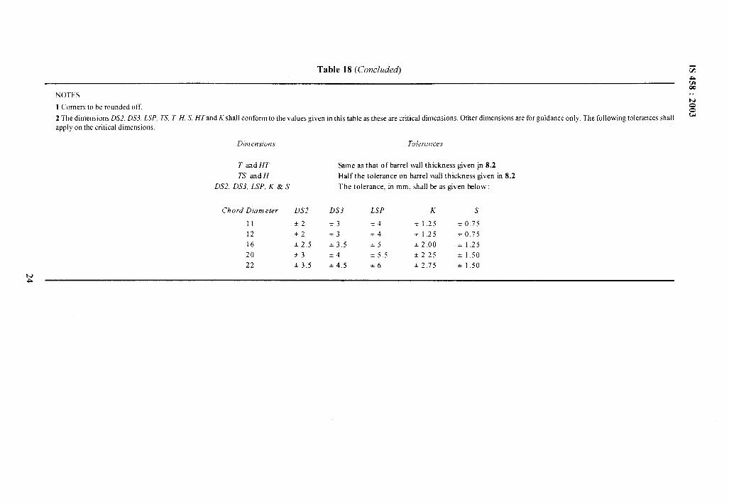
Table 18 (CorIc/u&~ GAm
NOTESw. .
1 Corners to be rounded offwo
2 The dimensions D.S2. DS3, LSP, TS, Z H. S, HTand A’ shall conform to the values given in this table as these are critical dimensions. Other dimensions are for guidance only. The following tolerances shall w
aPPU onthe critical dimensions.
o
Dim ensiot?s Tolerances
T and HT Same as that of barrel wall thickness given jn 8.2
TS and H Half the tolerance on barrel wall thickness given in 8.2
DS2, DS3, LSP,K & S The tolerance. in mm. shall lx as given beloIv:
Chord Dtameter DS2 DS3 LSP K s
11 *2 i3 +4 + 1.25 * 0.75
12 %2 *3 +4 i 1.25 + 0.75
16 h2.5 *3,5 +5 * 2.00 * 1.25
20 *3 54 +5,5 + 2.25 * 1.50
22 &3.5 *4.5 *6 * 2.75 ● 1.50
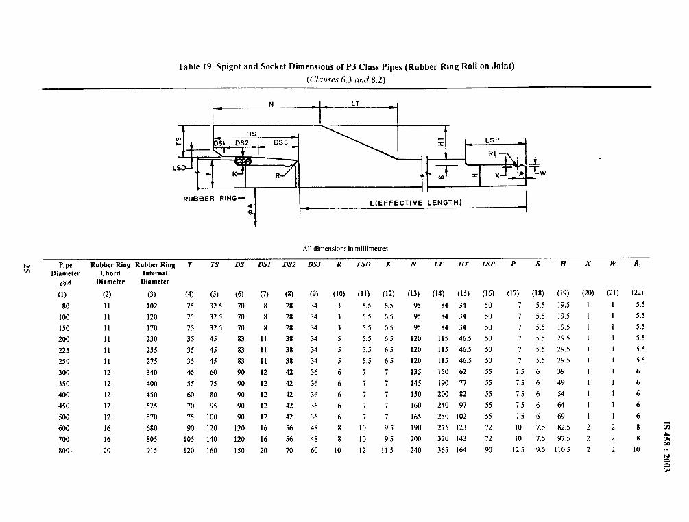
Table 19 Spigot and Socket Dimensions of P3 Class pipes (Rubber Ring Roll on Joint)
(Clauses 6.3 and 8.2)
N LT .
~ , G< ~, ,, .
0sw+ S1 DS2 DS 3
I.SDI- K R co
RuBBER RING-< L(EFFECTIVE LENGTH)s
(5) (6)
32.5 70
32.5 70
32.5 70
45 83
45 83
45 83
60 90
75 90
80 90
95 90
100 90
120 120
140 120
160 150
(7)
8
8
8
11
11
11
12
12
12
12
12
16
16
20
(8)
28
28
28
38
38
38
42
42
42
42
42
56
56
70
All dimensions in millimetres.
N Pipe Rubber Ring Rubber Ring T TS DS DSI DS2 DS3 R LSD K N LT HT LSP x w R,VI Diameter Chord Internal
DA Diameter Diameter
(1) (2) (3) (4)
80 11 102 25
100 11 120 25
150 11 170 25
200 11 230 35
225 11 255 35
250 11 275 35
300 12 340 4$
350 12 400 55
400 12 450 60
450 12 525 70
500 12 570 75
600 16 680 90
700 16 805 105
800 20 915 120
(9) (lo) (11) (12)
34 3 5.5 6.5
34 3 5.5 6.5
34 3 5.5 6.5
34 5 5.5 6.5
34 5 5.5 6.5
34 5 5.5 6.5
36 6 7 7
36 6 7 7
36 6 77
36 6 7 7
36 6 7 7
48 8 10 9.5
48 8 10 9.5
60 10 12 11.5
(13)
95
95
95
120
120
120
135
145
150
160
165
190
200
240
(14) (15) (16)
84 34 50
84 34 50
84 34 50
115 46.5 50
115 46.5 50
115 46.5 50
150 62 55
190 77 55
200 82 55
240 97 55
250 102 55
275 123 72
320 143 72
365 164 90
PSH
(17) (18) (19)
7 5.5 19.5
7 5.5 19.5
7 5.5 19.5
7 5.5 29.5
7 5.5 29.5
7 5,5 29.5
7.5 6 39
7.5 6 49
7.5 6 54
7.5 6 64
7.5 6 69
10 7.5 82.5
10 7.5 97.5
12.5 9.5 110.5
(20)
1
1
1
1
1
1
1
1
1
I
1
2
2
2
(21)
1
1
1
1
1
1
I
1
1
1
I
2
2
2
(22)
5.5
5.5
5.5
5.5
5.5
5.5
6
6
6
6
6
8 G
8 &00
10 . .Mo0u
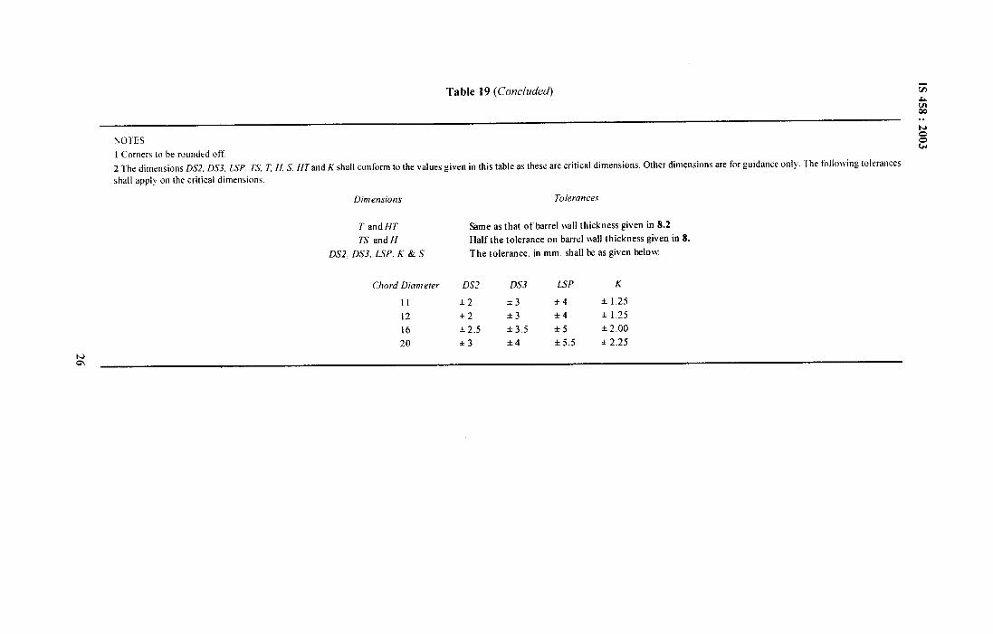
Table 19 (Concluded) G
%Oe. .N
NOTES o
1 Corners to be rounded off.
ou
2 The dimensions DS2, DS3, LSP, T’S, T H, S, HT’and K shall conform to the values given in this table as these are critical dimensions, Other dimensions are for guidance only. The following tolerances
shall apply on the critical dimensions.
Dimensions Tolerances
T and HT Same as that of barrel wall thickness given in 8.2
TS and H Half the tolerance on barrel mall thickness given in 8.
DS2, DS3, LSP. K & S The tolerance. itr mm. shall lx as given below
Chord Diameter DS2 DS3 LSP K
11 ● 2 *3 *4 + 1.25
12 +2 *3 +4 ● 1.25
16 *2.5 *3.5 *5 * 2.00
20 +3 *4 *5.5 k 2.25
:
1S 458:2003
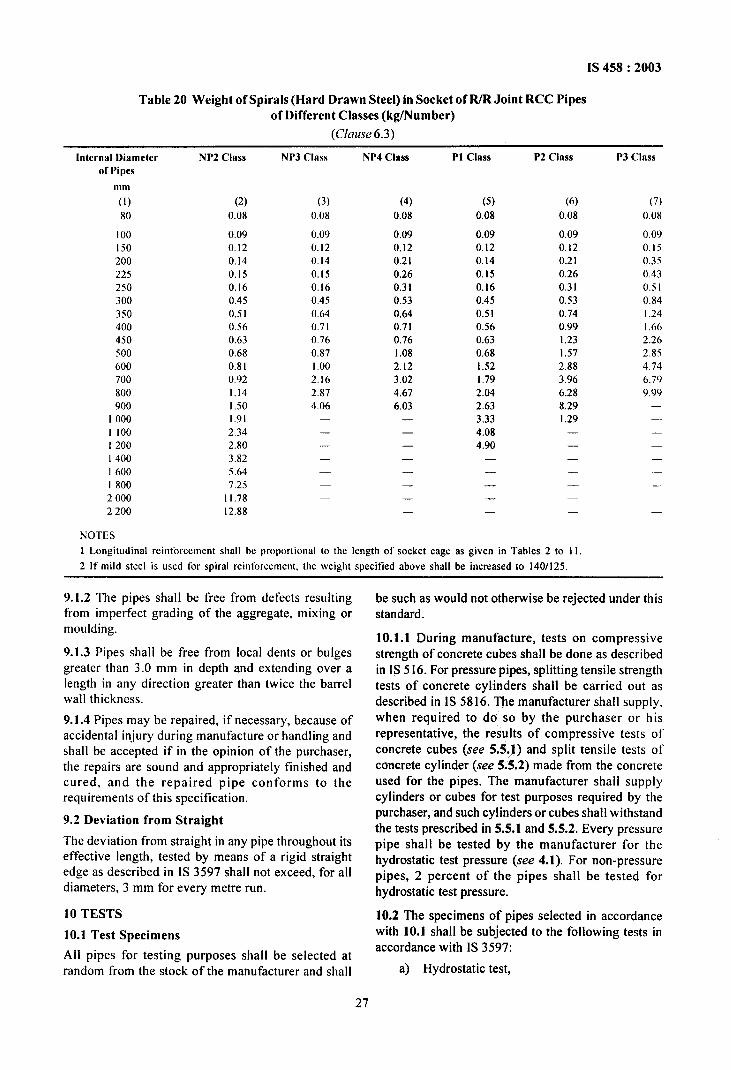
Table 20 Weight of Spirals (Hard Drawn Steel) in Socket of R/R Joint RCC Pipesof Different Classes (kg/Number)
(CfuZLse6.3)
Irrterrwl Diameter
of Pipes
111111
(1)
80
I 00I 50200
225250
300350
400450
500600700
800900
10001 1001200
I 400160018002000
2200
NP2 Class
(2)
0.08
0.09
0.12
0.14
0.15
0.16
0.45
0.51
0.56
0.63
0,68
0.81
0.92
1.14
1.50
1,91
2.34
2.80
3.82
5.64
7.25
11.78
12.88
NP3 Class
(3)
0.08
0.090.120.14
0.150.160.45
0.640.710.760.87I ,00
2.162,874,06
.———
(4)
0.08
0.09
0.12
0.21
0.26
0.31
0.53
0.64
0.71
0.76
1.08
2.12
3.02
4.67
6.03—
—
—
—
—
—
.
—
PI Class
(5)
0.08
0.09
0.12
0.14
0.15
0.16
0.45
0.51
0.56
0.63
0.68
1.52
1,79
2.04
2.63
3.33
4.08
4.90—
—
—
—
—
P2 Class
(6)
0.08
0.09
0.12
0.21
0.26
0.31
0,53
0,74
0.99
1.23
1.57
2.88
3.96
6.28
8.29
1.29.
—
—
—
—
—
NOTES
1 Longitudinal reinforcement shall be proportional to the length of socket cage as given in Tables 2 to 11.
2 It’ mild steel is used for spiral reinforcement, the weight specitied above shall be increased to 140/125.
P3 class
(7)
0.08
0.09
0.150.350.43
0.5 I0.84
1.241.662.262.8S4.74
6.799,99
—
—
———
9.1.2 The pipes shall be free from defects resultingfrom imperfect grading of the aggregate, mixing ormoulding.
9.1.3 Pipes shall be free from local dents or bulgesgreater than 3.0 mm in depth and extending over alength in any direction greater than twice the barrelwall thickness.
9.1.4 Pipes may be repaired, if necessary, because ofaccidental injury during manufacture or handling andshall be accepted if in the opinion of the purchaser,the repairs are sound and appropriately finished andcured, and the repaired pipe conforms to therequirements of this specification.
9.2 Deviation from Straight
The deviation from straight in any pipe throughout itseffective length, tested by means of a rigid straightedge as described in IS 3597 shall not exceed, for alldiameters, 3 mm for every metre run.
10 TESTS
10.1 Test Specimens
All pipes for testing purposes shal I be selected atrandom from the stock of the manufacturer and shall
be such as would not otherwise be rejected under thisstandard.
10.1.1 During manufacture, tests on compressivestrength of concrete cubes shall be done as describedin IS 516. For pressure pipes, splitting tensile strengthtests of concrete cylinders shall be carried out asdescribed in IS 5816. me manufacturer shall supply,when required to do so by the purchaser or hisrepresentative, the results of compressive tests ofconcrete cubes (see 5.5~1) and split tensile tests ofconcrete cylinder (see 5.5.2) made from the concreteused for the pipes. The manufacturer shall supplycylinders or cubes for test purposes required by thepurchaser, and such cylinders or cubes shall withstandthe tests prescribed in 5.5.1 and 5.5.2. Every pressurepipe shall be tested by the manufacturer for thehydrostatic test pressure (see 4.1). For non-pressurepipes, 2 percent of the pipes shall be tested forhydrostatic test pressure.
10.2 The specimens of pipes selected in accordancewith 10.1 shall be subjected to the following tests inaccordance with IS 3597:
a) Hydrostatic test,
27
IS 458:2003
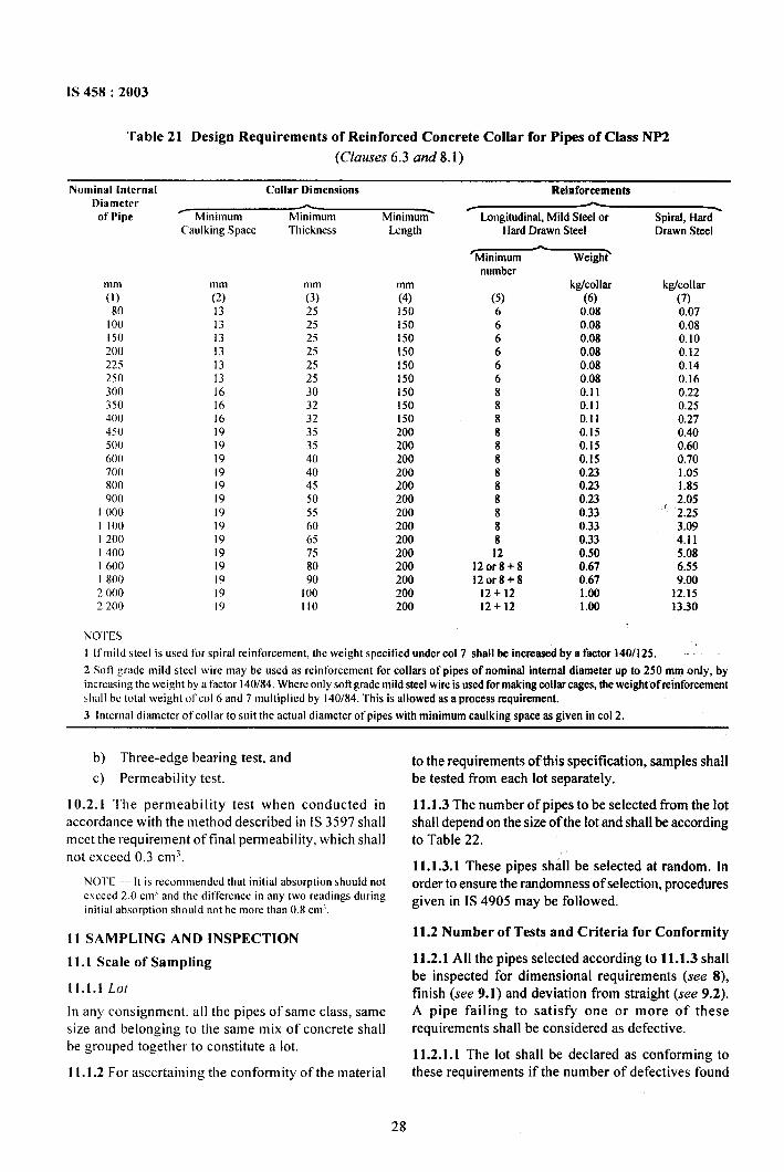
Table 21 Design Requirements of Reinforced Concrete Collar for Pipes of Class NP2
(Clauses 6.3 and 8.1)
Nominal lrrterml Collar Dimensions ReinforcementsDiameter —of Pipc = Minimum Minimum Minimum-
mm
(1)
80
I 00150200
225250300350400450
500
600”700800900
I 000
1 1001200
I 40016001800
20002200
(’mdking Space
mm(2)
1313131313131616161919191919
191919191919191919
Thickness
mm(3)
252525
25
2525
303232353540404550556065758090
100110
Length
mm(4)I 50150150150150150150150150200200200200200200200200200200200200200200
/ — \Longitudirrat, Mild Steel or Spiral, H&d
Hard Drawn Steel Drawn Steel
A‘Minimum Wei@T
numberkg/collar kg/collar
(5) (6) (7)6 0.08 0.076 0.08 0.086 0.08 0.106 0.08 0.126 0.08 0.146 0.08 0.168 0.11 0.228 0.11 0.258 0.11 0.278 0.15 0.408 0.15 0.608 0.15 0.708 0.23 1.058 0.23 1.858 0.23 , 2.058 0.33 2.258 0.33 3.098 0.33 4.1112 0.50 5.08
120r8+8 0.67 6.55120r8+8 0.67 9.00
12+12 1.00 12.1512+12 1.00 13.30
NOITS
I [t’ mild s[cel is used for spiral reinforcement, the weight specified under COI 7 shall be increased by a factor 140/125.
2 Soft grade mild steel wire may be used as reinforcement for collars of pipes of nofoinal internal diameter up to 250 mm only, by
incrctising the weight by a factor 140/84, Where on]y sott grade mild steel wire is used for making collar cages, the weight of reinforcement
shall bc total weight ot’col 6 and 7 moltiplicd by 140/84. This is allowed as a process requirement.
3 Internal diameter of collar to suit the actual diameter of pipes with minimum caulking space as given in cot 2.
b) Three-edge bearing test, and
c) Permeability test.
10.2.1 The permeability test when conducted inaccordance with the method described in IS 3597 shallmeet the requirement of final permeability, which shallnot exceed 0.3 ems.
NOTE — It is recommended that initial absorption should not
exceed 2.0 cm~ and the dit’ferencc in any two readings during
initial absorption should not be more than 0,8 cnll,
11 SAMPLING AND INSPECTION
11.1 Scale of Sampling
11.1.1 Lot
In any consignment, all the pipes of same class, samesize and belonging to the same mix of concrete shallbe grouped together to constitute a lot.
1I.1.2 For ascertaining the conformity of the material
to the requirements oilbis specification, samples shall
be tested from each lot separately.
11.1.3 The number of pipes to be selected from the lotshall depend on the size of the lot and shall be accordingto Table 22.
11.1.3.1 These pipes shall be selected at random. [norder to ensure the randomness of selection, proceduresgiven in IS 4905 maybe followed.
11.2 Number of Tests and Criteria for Conformity
11.2.1 All the pipes selected according to 11.1.3 shallbe inspected for dimensional requirements (see 8),finish (see 9.1 ) and deviation from straight (see 9.2).A pipe failing to satisfy one or more of theserequirements shall be considered as defective.
11.2.1.1 The lot shall be declared as conforming tothese requirements if the number of defective found
28
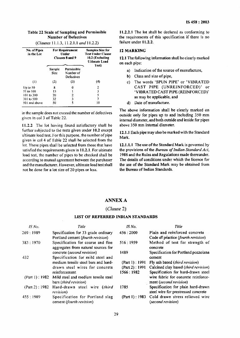
1S458:2003
Table 22 Scale of Sampling and PermissibleNumber of Defective
(Clauses 11.1.3, 11.2.1.1 and 1 1.2.2)
No. of Pipesin the Lot
(1)
up to 5051 to 100101 to300301 to 500501 and above
For Requirement Samples Size forUnder Test [Inder Clause
Clauses 8 and 9 10.2 (Excluding(Jltimate Load
T * . Test)Sample Permissible
Size Number ofDefective
(2) (3) (4)
8 0 213 1 320 2 532 3 750 5 10
in the sample does not exceed the number of defectivegiven in co] 3 of Table 22.
11.2.2 The lot having found satisfactory shall befurther subjected to the tests given under 10.2 exceptultimate load test. For this purpose, the number of pipegiven in COI4 of Table 22 shall be selected from thelot. These pipes shall be selected from those that havesatisfied the requirements given in 11.2.1. For ultimateload test, the number of pipes to be checked shall beaccording to mutual agreement between the purchaserand the manufacturer. However, ultimate load test shallnot be done for a lot size of 20 pipes or less.
IS No.
269:1989
383:1970
432
(Part l): 1982
(Part 2): 1982
455:1989
11.2.2.1 The lot shall be declared as conforming tothe requirements of this specification if there is nofailure under 11.2.2.
12 MARKING
12.1 The following information shall be clearly markedon each pipe:
a) Indication of the source of manufacture,
b) Class and size of pipe,
c) The words ‘SPUN PIPE’ or ‘VIBRATEDCAST PIPE (UNREINFORCED)’ or‘VIBRATED CAST PIPE (REINFORCED)’as may be applicable, and
d) Date of manufacture.
The above information shall be clearly marked onoutside only for pipes up to and including 350 mminternal diameter, and both outside and inside for pipesabove 350 mm internal diameter.
12.1.1 Each pipe may also be marked with the StandardMark.
12.1.1.1 The use of the Standard Mark is governed bythe provisions of the Bureau of Indian Standard Act,1986 and the Rules and Regulations made thereunder.The details of conditions under which the licence forthe use of the Standard Mark may be obtained fromthe Bureau of Indian Standards.
ANNEX A
(Clause 2)
LIST OF REFERRED INDIAN STANDARDS
Title
Specification for 33 grade ordinaryPortland cement ~ourth revision)
Specification for coarse and fineaggregates from natural sources forconcrete (second revision)
Specification for mild steel andmedium tensile steel bars and hard-drawn steel wires for concretereinforcementMild steel and medium tensile steelbars (third revision)
Hard-drawn steel wire (thirdrevision)
Specification for Portland slagcement Vourth revision)
IS No.
456:2000
516:1959
1489
(Part 1): 1991(Part 2): 1991
1566:1982
1785
(Part 1): 1983
Title
Plain and reinforced concrete —Code df pfactice ~ourth revision)
Method of test for strength ofconcreteSpecification for Portland pozzolanacementFly ash based (third revision)
Calcined clay based (third revision)Specification for hard-drawn steelwire fabric for concrete reinforce-ment (second revision)Specification for plain hard-drawnsteel wire for prestressed concreteCold drawn stress relieved wire(second revision)
29
IS 458:2003
IS No.
(Part2) :19831786:1985
2062:1999
3597:1998
3812:1981
4905: 1%8
5382:1985
Title
As drawn wire (/irst revision)
Specification for high strengthdeformed steel bars and wires forconcrete reinforcement (third
revision)
Steel for general structural purposes— Specification (fifth revision)
Methods of test for concrete pipes(second revision)
Specification for fly ash for use aspozzolana and admixture (firstrevision)
Methods for random samplingSpecification for rubber sealing ringsfor gas mains, water mains and sewers@rst revision)
IS No.
5816:1999
7322:1985
8041:1990
8043:1991
8112:1989
9103:1999
12269:1987
12330:1988
Title
Splitting tensile strength of concrete— Method of test first revision)Specification for specials for steelcylinder reinforced concrete pipes(fwst revision)
Specification for rapid hardeningPortland cement (second revision)
Specification for hydrophobicPortland cement (second revision)Specification for 43 grade ordinaryPortland cement (.&st revision)Concrete admixtures — Specifica-tion (first revision)Specification for 53 grade ordinaryPortland cementSpecification for sulphate resistingPortland cement
30
Bureau of Indian Standards
BIS is a statutory institution established under the Bureau of Indian Standards Act, 1986 to promoteharmonious development of the activities of standardization, marking and quality certification of goodsand attending to connected matters in the country.
Copyright
BIS has the copyright of all its publications. No part of these publications may be reproduced in any formwithout the prior permission in writing of BIS. This does not preclude the free use, in the course ofimplementing the standard, of necessary details, such as symbols and sizes, type or grade designations.Enquiries relating to copyright be addressed to the Director (Publications), BIS.
Review of Indian Standards
Amendments are issued to standards as the need arises on the basis of comments. Standards are also reviewedperiodically; a standard along with amendments is reaffirmed when such review indicates that no changes areneeded; if the review indicates that changes are needed, it is taken up for revision. Users of Indian Standardsshould ascertain that they are in possession of the latest amendments or edition by referring to the latest issue of‘BIS Catalogue’ and ‘Standards: Monthly Additions’.
This Indian Standard has been developed from Doc : No. CED 53 (6006).
Amendments Issued Since Publication
Amend No. Date of Issue Text Affected
BUREAU OF INDIAN STANDARDS
Headquarters :
Manak Bhavan, 9 Bahadur Shah Zafar Marg, New Delhi 110002 Telegrams: ManaksansthaTelephones :23230131,23233375,2323 9402 (Common to all offices)
Regional Offices : Telephone
Central : Manak Bhavan, 9 Bahadur Shah Zafar Marg
{
23237617NEW DELHI 110002 23233841
Eastern : 1/14 C.I.T. Scheme VII M, V. I. P. Road, Kankurgachi
{23378499,23378561
KOLKATA 700054 23378626,23379120
Northern : SCO 335-336, Sector 34-A, CHANDIGARH 160022
{
603843609285
Southern : C. LT. Campus, IV Cross Road, CHENNAI 600113
{
22541216,2254144222542519,22542315
Western : Manakalaya, E9 MIDC, Marol, Andheri (East)
{
28329295,28327858MUMBAI 400093 28327891,28327892
Branches : AHMEDABAD. BANGALORE. BHOPAL. BHUBANESHWAR. COIMBATORE. FARIDABAD.GHAZIABAD. GUWAHATI. HYDERABAD. JAIPUR. KANPUR. LUCKNOW. NAGPUR.NALAGARH. PATNA. PUNE. RAJKOT. THIRUVANANTHAPURAM. VISAKHAPATNAM.
Printed at PrabhatOffsetPress,New DeOii-2