Embed Size (px)
Citation preview

Development of Railwy Signal &Telecom Systems on IR
By ,M.C.Yadav WM/Signal/SWS Sabarmati/Western Railway
Indian Railway Engineering
On 16th April 1853 the first train between Boribunder (present day CSTM) and
Thana (present day Thane) chugged along the sole Railway line and thus began India’s
long and enduring tryst with the Railways. Great Peninsular Railways had managed to
tug at the heartstrings of the simple Indians with their steam locomotive and the carriages
following it. A century and half after the historical journey we still find ourselves in awe
of this transportation system, although the initial feeling of apprehension followed by
euphoria has now been replaced by cynicism and frustration. The fact is that Indian
Railways, in spite of its various shortcomings, have stood the test of time.
Let us embark on a journey through the annals of Railway Engineering via our very own,
Indian Railways …….
Railway Constructions – Architectural Grandiose!!!
The earliest of Railway stations were merely unimpressive sheds providing a 'landing'
place for incoming trains. But as rail transport gained popularity among Indians the
importance of this structure was realized and attempts made to enhance its appearance
and utility. One of the earliest Railway stations to be an example of sheer architectural
finesse is the Victoria Terminus in Mumbai, formally opened in 1887, with a series of
well proportioned and delicately ornamented arches, giving it a look of a grand cathedral.
Out of the seven Railway stations in the world having the longest ailway platforms, as
many as five are in India. Now isn’t that something to be proud of!!!
Today Railway stations are being given the shape of large complexes and besides
having the usual amenities like retiring rooms, restaurants, Kiosks, ATMs etc, they now
include large office areas. Over bridges are now being replaced by underground passages
providing more space above, on the platforms.
Railway Coaches – Mobile Homes!

Earliest Railway coach was a rectangular wooden open box affixed to wheels with
benches (rough wooden boards without backs) for seating passengers, exposing the
passengers to the elements of nature. The coaches were connected by a primitive system
of loose couplers, which jolted the passengers whenever the brakes were applied or the
train accelerated.
. The design was colorful and looked like a stagecoach or horse carriage. In 1885, an all-
steel under frame as developed in Europe was introduced in India. New Coaches
developed at Chennai in 1940’s were world class with all steel, fully welded lightweight
integral construction. These coaches were also anti-telescopic which meant high safety to
the passengers in the event of train accidents. The present day coaches continue to be
built in the same vein. Air-conditioned coaches were introduced in India in 1936.
Today IR proposes to have in-train internet, TV and telephony; so that the commuters
need not waste their valuable time staring at co–commuters or ruing over the couple of
hours lost traveling to and fro in trains. Commuters will then be able to check their
emails, check out what’s going on in the world around or even carry out their daily
transactions within the train. So much for commuter satisfaction!
Rail Locomotives–Tugging Along!
In India Steam Trains were initially introduced for passenger and goods service.
Thereafter the steam locomotives were utilized for handling goods and passenger trains
for a long time. General Electric introduced the first Diesel engine in Indian Railways in
1945. First Electric Locomotive (1500V DC) was commissioned in 1961. Now Traction
is on 25 KV AC.

Railway Communications
In the good old days, as the last millennium was coming to a close, the trains moved
around without communications. Telegraph & Telephony progressively came into
existence in India through Railways requirements. Earliest lines sanctioned in the
direction of Rail routes were from Calcutta to Peshawar and Bombay area. Later, for
longer distances, IR started using microwave communications (2GHz and 7GHz
(7.125GHz and 7.425GHz) for administration, 8GHz and 18GHz for control
communications) with backup wire line telephony. The microwave links besides having
more bandwidth than the older telephony cables also avoid the problem of cable theft.
Most links have 120 channels and more recent ones (post-1987) have 960 channels. The
four major metropolises are interconnected by a digital 34+2 Mbps microwave channel.
In addition, spread-spectrum CDMA communication is in use between a few stations
(Mumbai-Wadi on CR, Wadi-Secunderabad on SCR). Other major routes, not covered by
these, have UHF TDMA links.

With the advent of IT, computers have made the job of traffic controllers a lot easier.
Today, major stations' computer networks are also connected via trackside cables.
Control communications and control (the SCADA system) for electric traction
substations is usually done through trackside metal cabling. Since about 2000, a major
effort has been underway to provide optical fiber communication links between stations.
So far, fiber-optic links have been provided along the routes among New Delhi,
Ahmedabad, Mumbai, Pune, Bangalore, Chennai, Hyderabad, and Kolkata. Since about
1999, handheld radio sets (walkie-talkies) have been issued to most drivers, guards, and
other staff on the move. These handsets usually have a fairly short range (a kilometer or
so). VHF radio sets have been installed in the loco cabs for a few important trains such as
the Grand Trunk Express, Tamil Nadu Express, and the Rajdhanis and Shatabdis, for
communication between the loco and station controllers. Some systems like the Delhi
Metro also use mobile radio systems for train communication; the radio system is
integrated into the larger system of communication, which includes optical-fiber
communication between stations, etc.
Microwave tower.
Railway Signaling – Train Ahead!
Signaling is one of the most important aspects of Railway communication. In the very early days of the Railways there was no fixed signaling to inform the driver of the state of the line ahead. Trains were driven “on sight”. But several unpleasant incidents accentuated the need for an efficient signaling system. Earliest system involved the Time Interval technique. Here time intervals were imposed between trains mostly around 10 mins. But due to the frequent breakdown of trains in those days this technique resulted in rear-end collisions. This gave rise to the fixed signaling system wherein the track was divided into fixed sections and each section was protected by a fixed

signaling. This system is still being continued although changes have been brought about in the basic signaling methods. Earlier mechanical signals were used but today block signaling is through electric instruments.
In the mid 19th century mechanical interlocking was used. The purpose was to prevent the route for a train from being set up and its protecting signal cleared if there was already another conflicting route setup. The most modern development in signal interlocking is SSI- a means of controlling the safety requirements at junctions using electronic circuits which replaced the relay systems supplied up to that time. In Indian Railways, first trial installation of SSI was provided at Srirangam station in 1987. Nowadays Track Circuits are used wherein the current flow in the track circuit will be interrupted by the presence of wheels and a “stop” signal will be shown. A “proceed” signal will be displayed if the current flows.
Today the Mumbai Suburban Section is providing with Auxiliary Warning System. It continuously monitors the speed and whenever a motorman passes a signal at “red”, applies emergency brakes to bring the train to a halt.
Non Electric Signals along the track
Speed Limit
Number on triangular yellow board: speed limit in km/h. 'KMPH' or 'KM/H' may
optionally appear below the number. Black text.
Sometimes the board has additional text, for instance 'RAJDHANI ONLY' may appear at
the bottom, indicating that the speed is restricted for the Rajdhani service on this stretch.
Number on blue board: indicates a special speed limit (in km/h) for Rajdhani and
Shatabdi trains. Text is in white.

Termination Indicator: Termination of speed limit
Termination Indicators T/P, T/G, Termination of speed zone for, respectively, passenger
trains, goods trains.
Caution Indicator Arrow-shaped boards pointing to the left or right. These indicate
special restrictions on the track (temporary or permanent engineering restrictions) and
caution orders in effect; the direction of the arrow indicates which track the restriction
applies to. These boards are usually reflective yellow with black markings. The post on
which it is mounted has alternating black and white bands.. The caution indicator is
usually placed 700 m before a Speed Indicator board (see below) and 800 m before the
actual point of permanent way work or other cause of restriction. Drivers have to slow
down to the speed indicated on the speed restriction board by the time they reach it.

Other indicators include 'CP’ or 'CG' on small white circular boards. These are caution
indicators for passenger and goods trains, respectively. A 'C/T' indicator has been spotted
in a few cases just before the entrance to a tunnel.
Stop Indicator A rectangular board with red and white bands. It is mounted on a post
with alternating red and white bands. At night the sign is illuminated by two red lamps.
This is used for temporary or permanent engineering restrictions which call for trains to
come to a dead stop before proceeding. At stations these stop signs are used to position
the train correctly along the platform
Whistle Indicators 'W', or 'W/L' on a square yellow board. The 'W' is a general
whistle indicator while the 'W/L' stands for Whistle for Level Crossing. The latter is also
seen in Hindi with the characters 'see/pha' == 'seetee bajao - phatak'
Grade Indicator Ground level signs on a concrete slab base, with a number and an
upward or downward pointing arrow, indicating a grade. A number '500', for instance,
indicates a grade of 1 in 500. Black on white.
Sighting Boards The most common kind of signal sighting board is a rectangular
reflective board with a circle and two horizontal lines, yellow on black. This warns the
driver of a signal ahead. The next signal should be visible from this point onwards,

although in practice experienced drivers spot the signals well before the sighting boards
are crossed. In lower quadrant territory, there are often two sighting boards used for
signals. One, as described, is the goods signal sighting board and is placed 1400m
before the signal. The other is the passenger signal sighting board intended for use by
drivers of passenger trains and is usually placed about 1000m before the signal. The latter
consists of a rectangular reflective board with alternate black and yellow diagonal stripes.
Hand Signals - flags, lamps, bells, and whistles
Hand signals include signals given by hand, or by flags or lamps used by the signalman,
drivers, guards, or station staff.
At most stations and signalbox cabins, it is still customary to use hand-held flags (green
and red) to signal trains. In many cases these confirm the semaphore or colour-light
signals, but can be used to override them. At night hand-held lamps (red or green) are
used instead. The all-right signal refers to the display of green flags by station masters
(or other staff), lineside workers, level crossing gatekeepers, and others, to passing trains,
or for the driver of one train to another passing train (see drivers' signals below), or from
the signal cabin to the driver or guard of a passing train. It indicates a few different
things. For trains passing stations, it is a confirmation that the train is allowed to be
passing through as the semaphore or colour light signal indicates. The station staff person
also keeps a watch for problems such as hot axles, derailed bogies or dragging
equipment, or parted couplers, and the green flag indicates there are no such problems
observed. Customarily, the green flag is held in the left hand, and the red flag is kept
ready to be displayed in case of a problem in the right hand - the custom arose from the
idea that the right hand is usually the more vigorous one for most people and the red
danger signal could be shown more promptly in case of a problem.
Other hand signals: When a train is to leave a station, a once common practice was for a
bell to be rung (6 to 8 beats) by the station master or other station official. The guard
would also blow on a whistle. These practices are now sporadic.

On the SER, 6 beats of the bell were used for a down train, and 8 for an up train. On WR,
from Vaitarna onwards 3 beats of the bell indicated the EMU train had left the previous
station but one, while 5 indicated it had just left the previous station, for trains going
away from Mumbai. For trains towards Mumbai, the beats would be sounded with an
extra pause.
When a train is about to start moving, normal practice is for the guard to show a green
flag or lamp upon seeing the green flag or lamp from the station official, or hearing the
bell rung on the platform. (See the all-ready signal in the hand signals below.) The
guard's indication is confirmed and repeated by the assistant driver showing a green flag
or lamp.
Automatic Signaling and train working systems
Interlocking
In railway signaling, an interlocking is an arrangement of signal apparatus that prevents
conflicting movements through an arrangement of tracks such as junctions or crossings.
The signaling appliances and tracks are sometimes collectively referred to as an
interlocking plant. An interlocking is designed so that it is impossible to give clear
signals to trains unless the route to be used is proved to be safe
In order to ensure that the signalling system never provides unsafe (conflicting) signals
and the points are not set for more than one train that might end up proceeding on to the
same section of track and hence suffering a collision, various schemes have been
developed to coordinate the settings of the points and the signals within the region
controlled by a signal box or signal cabin.
Absolute Block System of train working
'Absolute block' refers to a system where the track is considered to consist of a series of
sections, such that when one train is occupying a section of track (the block section), no
other train is allowed to enter that section. This is the most widely used system for
ordinary train routes.
A station or signal box controls a block section in one direction (from its rear), and no
train may enter that block in that direction without permission from that signal box (the
station or signal box is said to accept or receive the train). When a train has been
accepted, no other trains can be accepted on that block section until it has left that block
section.
Obviously the two signal boxes at either end of the block section have to tightly
coordinate their actions, especially in the case of block sections that allow bidirectional
movement on a single line. The permission to enter the block may be in the form of a
physical token carried by the train crew while the train is in the block, or may be implicit
in the aspects of signals governing access to the block.

The block section is usually taken to be the section of track from the most advanced
signal controlled by the station in the rear (usually the starter or advanced starter signal) ,
and the rearmost signal controlled by the station ahead (usually the home or outer home
signal).
Sometimes a long stretch between two stations may be formed into two or more block
sections (intermediate block) to increase track utilization. The same principle applies in
receiving a train from one intermediate block section into the next one. The signal
controlling entry to an intermediate block section may be operated by staff at one of the
stations, or may have a small signal box (block hut) where the signal is located.
In automatic block territory, however, there may be several block sections between
stations; the signals protecting entry to these sections are controlled entirely by the
movements of trains on the sections, as detected by track circuits.
The portions of track that lie between the rearmost outer signal controlled by a signal box
of a station to the most advanced starter signal controlled by a signal box of the same
station are said to be within station limits, or to form the station section. Thus, as one
goes along the track, one passes from the station limits of one station, through one or
more block sections, and then enters the station limits of the next station. The act of
admitting a train into station limits is termed reception, and the act of sending it out of
the station is termed dispatch.
The restriction on more than one train or rake occupying a block section is stringent and
can be lifted only in very special circumstances, some shunting operations, for repair and
maintenance work, or emergency operations. For instance, a material train may be sent
into a block section that already has other departmental vehicles on it. A traffic train may
be sent into a section that has an inspection trolley on the tracks. In all such cases,
appropriate caution orders are issued to the drivers of the trains involved, and the driver
of any vehicle that is proceeding into the block section in contravention of standard block
working rules must carry the appropriate authority to proceed.
Within station limits, however, trains may be moved around by the signalman or station
master without reference to other stations or signal boxes, and in fact, depending on the
rules for station working in effect for the station, shunting operations, calling-on signals,
etc. may allow more than one train to occupy a section of track within station limits.
There are many stations where two full trains are routinely moved to the same track, to
use the same platform (see the trivia section).
Station working rules are determined for each station in consideration of its peculiar track
layouts and facilities. Movements within station limits are generally restricted to a lower
speed (15km/h) except for through trains on the main running line(s). Analogous to
station limits, yard limits are the regions associated with marshalling yards, sheds, etc.
where the requirements of shunting or other activity make it desirable to relax the
requirements on the number of trains or vehicles occupying a section of track.

Intermediate Block Section
Intermediate Block Sections are provided to increase track usage in areas with absolute
block operations where the distances between successive stations are large, causing each
block to be very long. The heart of the absolute block system is the idea of only
permitting one train ever to be on a block at any time; however, if the block is very long,
this restriction reduces the possible traffic on the route.
An intermediate block section is an additional block section which does not necessarily
correspond to any station, and which is provided solely to decrease the block lengths.
Such intermediate block sections are generally used if block lengths would otherwise be
more than about 10-15 km. IR prefers block lengths to be on the order of 4 to 8 km, under
normal circumstances.
Normally an intermediate block section is guarded by a single stop signal (and perhaps a
distant) which is similar to the Home signal for a station. Once a train has crossed the
intermediate signal another train may be allowed into the preceding block, just as with
the block sections for stations. An intermediate block is usually controlled by the signal
box at the preceding station. E.g., between Dahanu and Gholvad on WR is an
intermediate block section, which is controlled by Dahanu in the Down direction and by
Ghovad in the Up direction.
Many intermediate sections have automatic signals using track circuitry to detect the
presence of a train; however, manual operations are not uncommon. An 'intermediate
block post' is a station (a class 'C' station) at the boundary of an intermediate block
section. Normally only a stop signal and a permissive signal are used for entry to the
intermediate block.
An intermediate block signal is usually provided with a callbox for the driver of a train to
talk to the station master or signalman of the controlling station in case the signal stays on
for long, as the location of the signal may be well out of visible or audible range of the
station, making it hard for the presence of the train to be noticed by the station.
If the signal is defective, the driver informs the station master of the station in the rear
(controlling the intermediate block), who then obtains a Line Clear notification from the
station master of the next station (with exchange of private numbers) and then authorizes
the driver to proceed past the defective intermediate block signal (again with exchange of
private numbers). If the phone itself is defective, the driver informs the guard and can
then pass the intermediate block signal after stopping at it for 5 minutes, and proceeding
at 15km/h (at 8km/h in low visibility) to the next station. Once the next station is
informed of the defective signal, the station in the rear is also informed of the situation
and thereafter the entire stretch between the two stations is treated as a single block
section. At that point following trains from the station in the rear will be allowed into the
block section with written authorization to pass the defective signal.

Intermediate block sections have no significance for crossing or precedence of trains
(express/passenger, freight/passenger) — they are purely provided to decrease the
headway or spacing between successive trains. Usually there is no interlocking of any
sort provided (i.e., there are no points to route a train differently as the intermediate block
signals change, there are no sidings or loops at the signals)..
Block instruments
These control the coordinated movement of trains on the block section; the block
instruments of the two stations or signal boxes at either end of the block section are
electrically interconnected for this purpose. (Normally a simple audio-frequency
modulated code transmitted over trackside or underground wires is used for this purpose;
earlier block instruments were connected directly (by DC voltages).) In physical token
block areas, the block instrument is also the device that dispenses the tokens, and hence is
also known as the token instrument.
In areas with track circuits (previous page) block working may be accomplished without
block instruments by using the information from the track circuit to coordinate the
aspects of signals using electric or electronic circuitry.
In automatic signalling areas, block working is handled by the track circuits connected to
the signalling system such that the movement of the trains controls the signals.
Block working can be done with axle counters(BPAC) too. Here, the task of deciding
whether a train has entered a section without parting can be automated by counting the
axles as they pass the last signal from the dispatching station and comparing with the
count of the axles at the home signal of the receiving station. If they match ('last vehicle
proving') the previous block can be opened for the next train. More often, though, axle
counters are used in conjunction with track circuits simply to detect the presence of a
train on a section for block working.
Communication between the two signal boxes these days is often by telephone, but in the
past telegraph instruments that sounded bell signals were universal, and these are still
used a lot today. The bell code used by IR is described below.
IR's classifies stations according to their role in the block system and their rules for
issuing Line Clear indications. See the section on stations for details.
Also see the extracts of IR General Rules on train working.
Mechanically operated interlocking
The most prevalent systems today are still mechanical interlocking schemes that
coordinate the positions of the levers controlling the points with the signals governing
that section of track and connected branches, loops, or sidings.

For instance, in one common scheme, a key that allows setting the points for a route has
to be obtained from the block instrument, and as long as the key is removed the
instrument cannot be set to provide Line Clear for a conflicting route. The wires that
operate signals, and the rods that control points, are all interconnected in the lever frames
at the signal cabins so that they are literally 'interlocked' -- the position of one lever or
key physically obstructs the movements of other levers and keys which control points or
signals that can be set in conflicting ways.
Manually operated interlocking
Neale's ball token system
The ball token system relies on the crew's physical acquisition and carriage of a small
metal ball to mark a train's permission to enter a section of track. The ball is dispensed by
a Token Instrument at either end of the block. The two instruments are interconnected so
that at any given time, one and only one ball can be handed out from either of them,
ensuring that only one train from either direction can enter the section of track ('block')
controlled by them.
The token is dispensed by the token instrument only when the block indication is set to
Train Going To (see above) after Line Clear has been granted and Train Coming From
has been set by the receiving station. While the ball token is carried by a particular train's
crew, no other train may enter that section of the track. The token instruments at either
end of the block will not give out any tokens until the token carried on the train currently
in the block is returned to one of the token instruments. The block indication at the
sending station cannot be changed from Train Going To until then. This is usually
supplemented by mechanical interlock systems for the points on successive blocks of the
tracks; changing the points at one block causes a notification at the signal box for the next
block.
The ball token may be engraved with the station codes for the stations at either end, and
usually also has a serial number. IR rules require the loco driver or assistant driver to
enter the serial number in a register carried in the locomotive cab. In some variants of the
ball token, such as tablet token systems, the token is so designed with different patterns
of grooves on it that it cannot be inserted into the token instrument of the next one or two
block sections beyond the section for which it was intended (in case it is carried beyond
the receiving station in error.
A bell or other telegraph mechanism between signal boxes provides for communication
of a few basic messages, such as whether the train is on a block, whether it has left the
block, whether permission is granted to enter the block, whether a train has had to stop
for an emergency in a block, whether it has had to reverse direction, etc. See the bell code
below for the full details.
When a train stops at a station, the driver or assistant driver relinquishes any token they
might have carried for the previous section, and picks up the token for the next section.

In case the train is 'passing through', i.e., not stopping at the station, the assistant driver
puts on a thick arm protector and leans out of the loco. One of the station staff carries a
reed and leather hoop about two feet in diameter with a pouch which holds the token. The
assistant driver in one rapid move drops the older token and picks up the fresh token from
this man standing on the ground. Then the assistant driver shows the green flag to the
station master as well as honks the horn to indicate a good 'pick up'. Then he shouts the
token number along with the section name to the driver who enters it in his log. The
token is picked up in the night in the same way, except the man from the station also
carries flaming kerosene soaked rag or lights a naphtha flare, to indicate his position in
the darkness. A short (3' - 4') upright piece or rail or post, usually all white, sometimes
with a stripe or two, and located close to the tracks, marks the position where the person
handing out the token has to stand for the token exchange.
Picking up a token by hand is generally done only at low speeds. At higher speeds the
hoop holding the token is actually mounted on a pick-up stand; the person on the ground
stands next to it with a green flag. A pick-up rod on the side of the loco is positioned in
just the right manner to snag the hoop and lift it off while the train is in motion.
Impromptu "shock absorbers" made of used hose-pipe lengths were used on the side of
the loco to prevent the token from being bumped around excessively thereby possibly
breaking the hoop or pouch.
(A) Aperture for inserting tokens through the aperture slot a ball token is put into the Block instrument.
(B) Galvanometer, this detects the flow of current from one instrument to another.

(C) Telephone, This is provided in conjunction with the instrument for communication with the station at the other end of the block section.
(D) Bell plunger. This is used for the transmission of Bell Code signals and operation of Operating Handle.
(E) Operating Handle. This has three positions, "Line Closed' ',"Train Going To", and "Train Coming From". It can · be turned to any one of these positions when a prolonged beat is received from the station at the other end of the block section. Note: When a token is dropped in, the Operating Handle can be brought to "Line Closed" position without the cooperation of the Station Master at the other end of the block section.
(F) Token Delivery cup, A token comes out through the token delivery cup
(G) Bell this corresponds to the Bell Code signals given by the station at the other end of the block section. At stations provided with, more than one instrument different 'bells or gongs with distinctive sounds are fitted up to identify the' individual instrument.
(H) Station Master's key, when the key is taken out, it locks the instrument in, the last operated position. This key should be kept in the personal custody of the Station Master when it is not required for operating the instrument.
(I) switches for controlling locks. The left-hand switch controls the token lock and shall be pressed while extracting the token. The right-hand switch shall be used when turning the handle to"Train Coming From" or clearing back or canceling.
(J) 'E' type lock with key in 'Train Going To' position. This is provided where the Last Stop signal is controlled mechanically through the Block Instruments. The key can be released only when the block handle is in "Train Going To" position and is used for controlling the Last Stop signal lever. This key can also be used for controlling the slip siding points.
(K) 'E' type lock with key in 'Train Coming From' position. This can be released only when the Operating Handle is in the "Train Coming From" position and is used for controlling the catch siding points.
Electrically operated interlocking
In the more advanced electrical or electronic interlocking schemes, the points and signals
are worked from one integrated mechanism in a signal cabin which features a display of
the entire track layout with indications of sections that are occupied, free, set for
reception or dispatch, etc. The interlocking is accomplished not by mechanical devices
but by electrical circuitry -- relays and switches in older electrical or electro pneumatic
systems, and computerized circuits in the newer electronic systems.
Panel Interlocking (PI) is the system used in most medium-sized stations on IR. In this,
the points and signals are worked by individual switches that control them.
Route Relay Interlocking (RRI) is the system used in large and busy stations that have
to handle high volumes of train movements. In this, an entire route through the station

can be selected and all the associated points and signals along the route can be set at once
by a switch for receiving, holding, blocking, or dispatching trains
Part of a relay interlocking.
When the signal/switch button and the route button are operated simultaneously,
concerned route initiation relay, LR picks up. Every signal will have as many LRs as that
number of routes and alternate overlap and routes.
The RRI’s main operating component is the control panel which is provided with
switches and buttons for operation of all functions as signals, point siding etc.
Geographical demarcation of track circuits, points, signals and all other functions with
illuminations as per their respective position is provided. A counter for registering
emergency operation is provided. Indicators for power supply availability, with
acknowledgement buttons are provided. Conditions like train on line and train arrival are
also available.
One main feature of route relay interlocking is that the buttons by which routes are
defined are placed directly on the track diagram, rather than underneath the diagram as on
CTC panels or conventional interlockers. Route relay panels generally display more
dynamic information about the state of an interlocking than the track occupancy lights
associated with earlier system
As an example, Old Delhi station has an RRI system from Siemens which allows
selection from among 1122 possible routes. CR has a large RRI system at Kurla which
controls signals from Ghatkopar to Sion on the Main Line, at Lokmanya Tilak Terminus,
and from Chembur to GTB Nagar on the Harbour Line. The first route-relay interlocking
system was set up on WR at Churchgate station control tower in the 1950s (equipment
from Siemens?).
Regardless of whether the mechanisms are controlled manually or by electronic
circuits, and whether they are operated mechanically or electrically, all interlocking
schemes usually enforce several or all of the following rules:
No signal can be pulled off unless corresponding points are set correctly.

Facing points are locked to the corresponding route when a signal is pulled off.
Signals for conflicting movements cannot be pulled off simultaneously.
Points for conflicting routes cannot be set simultaneously.
Trailing points are locked to the rear when a signal is pulled off.
Distant, warners, repeaters, etc. cannot be pulled off unless the corresponding stop
signals are pulled off.
Gate stop signals cannot be pulled off unless level-crossing gates are blocked to
road traffic.The description of the possible routes that can be set, and the corresponding
dispositions of points and signals are found in the locking table and selection table for a station.
The locking table lists the signals and points controlled; the levers at signal boxes (or control
panels at control centers) which operate various signals and points; which signals and points are
locked (and in what position) when other signals are pulled off or points set; which track circuits
are clear or occupied; etc.
The selection table lists the allowed non-conflicting routes that can be set. The terms
route selection, route locking, route holding, and route release are used to describe the
various steps in the process of picking a route for a train.
In various semi-automated systems of interlocking the electrical or electromechanical
mechanisms or the electronic circuitry takes over a large part of the bookkeeping details
that determine the sequences in which signals must be pulled off or points set to assign a
route to a train. In the more primitive mechanical interlocking systems, such a sequence
has to be manually followed; for this purpose the locking and selection tables are used by
the signalman, along with lever leads which indicate for each signal lever which other
levers must be set or cleared.
RRI and PI equipment is from Siemens and some British manufacturers. 247 stations
now have RRI installations and the number of stations with Panel Interlocking has risen
to 2,426.
EI (Electronic Interlocking)
Modern interlockings (those installed since the late 1980s) are generally solid state,
where the wired networks of relays are replaced by software logic running on special-
purpose control hardware. The fact that the logic is implemented by software rather than
hard-wired circuitry greatly facilitates the ability to make modifications when needed by
reprogramming rather than rewiring. In many implementations this vital logic is stored as
firmware or in ROM that cannot be easily altered to both resist unsafe modification and
meet regulatory safety testing requirements.
At this time there were also changes in the systems that controlled interlockings. Whereas
before technologies such as NX and Automatic Route Setting required racks and racks of
relays and other devices, solid state software based systems could handle such functions
with less cost and physical footprint. Initially processor driven Unit Lever and NX panels
could be set up to command field equipment of either electronic or relay type, however as
display technology improved, these hard wired physical devices could be updated with

visual display units, which allowed changes in field equipment be represented to the
signaller without any hardware modifications.
Solid State Interlocking (SSI) is the brand name of the first generation microprocessor-
based interlocking developed in the 1980s by British Rail, GEC-General Signal and
Westinghouse Signals Ltd in the UK. Second generation processor-based interlockings
are known by the term "Computer Based Interlocking" (CBI),[8]
of which MicroLok
(trademark of Union Switch & Signal, now Ansaldo STS), Westlock and Westrace
(trademarks of Invensys Rail) and Smartlock (trademark of Alstom) are examples.
(Computer-based controls for a modern electronic interlocking)
Automatic Block Signalling
In Automatic Block Signalling (ABS) the signals are automated and operate in
conjunction with track circuiting or other means of detecting the presence of a train in a
block section. [2/05] As of March 2003, IR had 3,606 kms of track under the ABS
system.

When a train enters a block section, the stop signal protecting that block changes
automatically to on or the Stop aspect. As the train moves ahead out of that block and
into the next block, the signal aspect changes automatically to Caution. In multiple-aspect
signalling, when the train is 2 blocks ahead the aspect then changes to Attention, and then
to Proceed when the train has passed 3 blocks ahead. In 3-aspect signalling, the aspect
changes to Proceed when the train is 2 block sections ahead. In automatic block territory
2-aspect signalling is not used.
The gray, white, or silver boxes marked 'LOC CAB' found by the side of the tracks
contain the circuitry to accomplish the automatic signal transitions. Any number of
automatic block stop signals may be provided in between two block stations; thus with
this system, the two stations do not define the ends of a single block section as is usually
the case with manual absolute block working (excepting, of course, the case of
intermediate block sections). Minimally one automatic stop signal is provided to the rear
of a block station's first stop signal.
The Home and Starter signals of a block station must be manual or semi-automatic (see
below) even in automatic block territory, and cannot be fully automatic (however, they
may still be operated remotely from a central location if the station does not have its own
control cabin, as with the Mumbai area sttaions that come under the TMS (Train
Management System) centralized traffic control system).
Note: Automatic Block Signalling is an American term and is the same as 'Track Circuit
Block' in British terminology; the American influence starting from the 1930s and
through the war years on signalling and interlocking developments in India probably led
to this usage in India.
Automatic signals are normally always in the clear position (Proceed aspect), except
when the next signal ahead is manually operated, in which case the normal aspect shown
is either Caution or Attention. Automatic block signals are provided with a small circular
plate marked 'A' (black on white) on the post of the signal or next to it. In contrast to
these, manual signals are worked by the signal operator and are normally always in the
on position and have to be explicitly pulled off by the operator.
There are also semi-automatic signals which can work either as automatic signals or in
manual mode. When working in manual mode, a semi-automatic signal assumes the on
position automatically when a train occupies a block section ahead of it just like an
automatic signal, and can be manually pulled off only after block sections ahead are
clear. These are provided with a small circular plate marked 'A' (black on white) which is
lit by a white lamp when the signal is working as an automatic block signal and not lit
when the signal is being worked manually.
Gate stop signals in automatic block territory are provided with both a 'G' marker as
noted above for gate signals, and also an 'A' marker (white on black). Calling-on signals
in automatic territory have the 'C' marker as usual in addition to the 'A' marker, and these

are found only at entrances to stations which have their own control cabins to decide the
calling-on aspects.
When approaching a fully automatic block stop signal which is on in automatic block
territory, the train must come to a standstill to the rear of the signal, but then in some
cases, after waiting for some time (normally 2 minutes, sometimes varies from day to
night -- 1 minute in daytime and 2 minutes at night), if the signal does not change aspect
the train may pass the signal at danger at a low speed (typically restricted to 15km/h),
with the driver alert for other vehicles or obstructions on the track. This is also allowed
on the Mumbai suburban networks when an automatic block signal has failed.
Incidentally, fully automatic signals often do not appear on the control panel at the
control towers.
TRACK CIRCUITS
Track-circuiting is mandatory in sections where visibility is a problem, shunting
operations are routinely carried out on the block section outside station limits on the main
running line, or if special situations exist, e.g., if the advanced starter is more than one
full train-length ahead of the most advanced trailing points of the station.
The track circuit provides additional functionality of detecting broken rails, though only
to a limited extent in AC traction areas and not in the common rail in DC traction areas.
Axle counters, however, offer no such facility. However, experience has shown that
broken rails often occur near the insulated block joints which are used to electrically
isolate adjacent track circuits. Since axle counters do not require such block joints, the
risk of having a broken rails is significantly reduced.
ELECTRICAL TRACK CIRCUIT
The most common form of track circuit used is the detection of a train by the closing of
an electrical circuit between the two rails because of the conducting nature of the rolling
stock. This circuit may use DC in the simplest form, or may use AC.
Principles and operation
The basic principle behind the track circuit lies in the connection of the two rails by the
wheels and axle of locomotives and rolling stock to short out an electrical circuit. This
circuit is monitored by electrical equipment to detect the presence or absence of the
trains. Since this is a safety appliance, fail-safe operation is crucial; therefore the circuit is
designed to indicate the presence of a train when failures occur. On the other hand, false
occupancy readings are disruptive to railroad operations and are to be minimized.
Track circuits allow railway signalling systems to operate semi-automatically, by
displaying signals for trains to slow down or stop in the presence of occupied track ahead
of them. They help prevent dispatchers and operators from causing accidents, both by

informing them of track occupancy and by preventing signals from displaying unsafe
indications.The basic circuit
Schematic drawing of track circuit for unoccupied block and occupied.

A track circuit typically has power applied to each rail and a relay coil wired across them.
Each circuit detects a defined section of track, such as a block. These sections are
separated by insulated joints, usually in both rails. To prevent one circuit from falsely
powering another in the event of insulation failure, the electrical polarity is usually
reversed from section to section. Circuits are commonly battery-powered at low voltages
(1.5 to 12 V DC) to protect against line power failures. The relays and the power supply
are attached to opposite ends of the section in order to prevent broken rails from
electrically isolating part of the track from the circuit.
When no train is present, the relay is energized by the current flowing from the power
source through the rails. When a train is present, its axles short (shunt) the rails together;
the current to the track relay coil drops, and it is de-energized. Circuits through the relay
contacts therefore report whether or not the track is occupied.
In almost all railway electrification schemes the rails are used to carry the return
current. This prevents use of the basic DC track circuit because the substantial traction
currents overwhelm the very small track signal currents.
To accommodate this, AC track circuits use alternating current signals instead of
DC currents. Typically, the AC frequency is in the range of audio frequencies, from 91
Hz up to a 250 Hz. The relays are arranged to detect the selected frequency and to ignore
DC and AC traction frequency signals. Again, fail safe principles dictate that the relay
interprets the presence of the signal as unoccupied track, whereas a lack of a signal
indicates the presence of a train. The AC signal can be coded and locomotives equipped
with inductive pickups to create a cab signalling system.
In this system, impedance bonds are used to connect items which must be electrically
connected but which must remain isolated for the track circuit to function.
AC circuits are sometimes used in areas where conditions introduce stray currents which
interfere with DC track circuits
For a track circuit to reliably detect the location of a train within its specified
section, the section must be electrically isolated from adjacent track (the exception being
with joint less AFTC -- see below). For this, IR uses special kinds of rail joints, known as
glued joints, especially on LWR (long welded rail) sections. Usually a special 940mm-
long fishplate is used with 6 holes for fish bolts. Special high tensile strength fish bolts
are used and the entire fishplate and bolt assembly is glued on to the joint, including the
'end post' at the joint, using an epoxy impregnated fabric in multiple layers. A typical
glued joint is 6.5m long and is welded to the adjoining rails. The glue and fabric ensure
that the rail sections on either side of the joint are electrically separated.
At normal joints within a track circuit section, electrical continuity must be ensured.
Usually, one or two bonding wires are provided that connect the two rails across a
fishplate joint. This is done even though the fishplate normally provides electrical

continuity, to allow permanent way operations that involve unbolting the fishplates to
continue without interfering with track circuiting. Also, dirt and surface impurities can
cause the bolted fishplate joint not to conduct electricity reliably for track circuiting
purposes (especially with AFTC or HFTC where the impedance of the joint to the
particular frequencies involved is critical). In a few cases special-purpose resonant bonds
or other devices are provided at joints to allow particular track circuit signals (AFTC or
HFTC) to flow while blocking others.
On most sections with track circuiting, track integrity checks are also provided with these
circuits, which electrically detect a break in the circuit which would indicate a break or
deformity in the rails. When interlocked with signals, this also prevents a signal from
being pulled off if the track has a defect. Of course, not all kinds of track defects can be
detected in this manner.
AFTC
Most zones now have many sections that use AFTC, or Audio-Frequency Track Circuit,
that sends modulated electrical signals at a particular frequency (a few kHz, often
831.33Hz) through the rails rather than relying on a simple circuit connectivity; this is
more reliable and allows the track circuit length to be increased a lot. The pioneers in
adopting AFTC over simple DC track-circuiting were WR, SR, and CR (Dombivli, Pune-
Lonavala, Chennai-Tambaram, Anand-Vatva, etc.). CR has also experimented with a
variant known as the High-Frequency Track Circuit (HFTC).
With joint less AFTC, electrical insulation is not necessary. Instead, detection of the
section occupancy by a train is done by measuring the attenuation of the signal which is
at a frequency (about 10kHz, usually) which does undergoes significant attenuation in
rails over the distances of interest and whose propagation characteristics are known. This
also means that the entrance of a train into the track circuit section is not determined
precisely based on its position -- instead, safety factors are incorporated in the
calculations to yield zones within which train occupancy can be determined in a
guaranteed fashion. As mentioned above, the signal is also coded in a pulse train allowing
the receiver to distinguish between signals of different track circuit sections.
In a variation of the joint less track-circuiting scheme, trackside units can be used to set
up a resonant circuit and constrain the signal (usually between 1.5kHz and 3kHz) to a
particular section of track. The advantage of joint less AFTC is clear in that insulated
joints are not required, reducing maintenance, allowing the use of long welded rail
sections, and eliminating the problems of insulated joint failures. Joint less AFTC
sections can be 1-1.5km in length.
Joint less track circuits use audio frequency tuned circuits to create what amounts to a
block joint.

Frequencies of the Aster SF 15 type track circuit are 1700 Hz and 2300 Hz on one track
and 2000 Hz and 2600 Hz on the other. These frequencies are modulated by a small
frequency.
TI21 type track circuits use the following frequencies;
A 1699 Hz Down line
B 2296 Hz Down line
C 1996 Hz Up line
D 2593 Hz Up line
E 1549 Hz Down line
F 2146 Hz Down line
G 1848 Hz Up line
H 2445 Hz Up line
A to D are used in two-track areas, while E to H are additional frequencies for use in
four-track areas.
Joint less track circuits eliminate most of the impedance bonds that electrified railways
would otherwise

require.
In the above system, the transmitter section (TX) feeds in the audio frequency signal to
the track through the tuning unit(TU). The audio frequency signal travels through the
track and received at the other end by the receiver (RX) through another tuning unit at the
receiving end. The receiver then operates the relay.
The media for the audio frequency signal is the rail and hence this system also detects for
the broken rails.Axle counter
An axle counter detection point

An axle counter is a device on a railway that detects the passing of a train in lieu of the
more common track circuit. A counting head (or 'detection point') is installed at each end
of the section, and as each axle passes a head at the start of the section, counter
increments. As the train passes a similar counting head at the end of the section, that
counter decrements. If the net count is evaluated as zero, the section is presumed to be
clear for a second train.
This is carried out by safety critical computers called 'evaluators' which are centrally
located with the detection points located at the required sites in the field. These detection
points are either connected to the evaluator via dedicated copper cable or via a
telecommunications transmission system. This allows the detection points to be located
significant distances from the evaluator. This is useful when using centralized
interlocking equipment but less so when signalling equipment is distributed at the
lineside in equipment cabinets.
Axle counters are used in places such as wet tunnels, like the Severn Tunnel, where
ordinary track circuits are unreliable. Axle counters are also useful where there are
uninsulated steel sleepers which prevent the operation of track circuits. Axle counters are
also useful on long sections where several intermediate track circuits may be saved.
In the figure shown:
A set of track inductors fitted at the entry and exit end of the track which COUNTS IN
and COUNTS OUT the number of axles passing over. These are transmitting coils which
generate magnetic flux on the flow of high frequency current. These coils are set opposite
to each other on each side of the rail. When the wheel passes through, it cuts the magnetic
flux and the induced voltage in the receiving coil is reduced, these dips are evaluated in
the evaluator and counted.An evaluator registers the counts and if the number at each end
is same then the section is CLEAR otherwise OCCUPIED.

The basic components of an axle counter are the following
1) Two or more track devices which ensure the entry and the exit points of a portion of a
portion of track is checked for the numbers of axles entering and the number of axles
going out.
2) Track side interface which buffer the signals of the track devices and amplify them for
counting at the centrally located counter where the input from both the ends come.
3) A counter which is connected to all the track side buffers and counts the axles coming
in and the axles going out.
4) A transmitter unit kept at all track side locations to feed signal to the track side
equipment for the purpose of detection of axles.
Specifications of analogue axle counter (Typical)
1) Operating Voltage : 24 V
2) Frequency used for monitoring: 5 KHz
3) Distance from the track side transmitter/ Buffer to Track : 15 m
4) Method used for detection of wheels : Electromagnetic
5) Length of track which can be monitored : Upto 15 Kms
6) Medium of Telecommunication between track devices and the counter unit: Copper
shielded cable 0.9 mm
7) No. of conductors used for the operation : 2 pairs for each track devices.
How it works
Double wheel detectors mounted on one of the rails detect the axles of the passing
vehicles. As they pass, the wheels change the alternating electromagnetic field between
the transmitter and receiver of each
Detector and hence the voltage induced in the receiving coil of the detector.
The changes in amplitude and their chronological sequence are evaluated.
The offset arrangement of transmitter and receiver permits direction-of-travel
Identification. The signals required for counting and determining the direction of travel
are transferred to the evaluation computer in the form of frequency- and amplitude
modulated signals.
The evaluation computer is the central processing and detection unit of the system. It
establishes an overall result from the detection information proceeding
from the counting heads and generates a track clear or track occupied indication, taking
account of the operating state. The track clear or track occupied indication
is output via two channels using floating relay contacts with opposite or the same normal
condition. The plug-in printed circuit boards of the evaluation computer are inserted into
a single-tier 19" rack. All inputs and outputs, including the power supply, plug into the
front/rear of the rack. The evaluation computer is fitted with LEDs and measuring
sockets. The LEDs are used for fault diagnosis and for the output of statistical
information. Usually, a board of the evaluation computer or counting head can be
determined to be the cause of a fault. The measuring sockets are used in conjunction with
some of the LEDs for adjusting and checking the system.

Disadvantages
Axle counters may forget how many axles are in a section for various reasons such as a
power failure. A manual override is therefore necessary to reset the system. This manual
override introduces the human element which may be unreliable too. An accident
occurred in the Severn Tunnel due to improper resetting of the axle counters.
There are three methods of securing the reset and restoration of axle counters into
service:
Co-operative reset requires both the technician and signaler to co-operate to reset
and then restore the section into service. This directly manages the cause of the
Severn Tunnel accident.
Preparatory reset uses the internal logic of the axle counter system to enforce
that a train must proceed through a reset section at slow speed, by holding its
output as 'occupied' until the train is successfully detected as passing through the
section. This logically proves the section free of obstruction and therefore allows
the section to change its output to 'clear'.
Conditional reset (with aspect restriction) has the section reset only if the last
count was in the outward direction. This at least shows that any trains in the
section at time of reset were at least moving out. The signal protecting the reset
section is held at danger by signalling logic outside of the axle counter evaluator
to enforce a low speed 'sweep' of the section prior to restoration to service.
Axle counter

Auxiliary Warning System
AWS or the Auxiliary Warning System is a system of providing some advance
notification of upcoming signal aspects to the motorman via a display panel in the driving
cab of the EMU. The advance notification is done through trackside electromagnets that
trigger relays in the passing EMU cabs. This was originally introduced by Western
Railway for its Mumbai EMUs in the early 1980s. Central Railway introduced AWS
somewhat later. Initially there were many teething problems with technology, including
problems of pilferage of the trackside equipment, but these were mostly resolved by the
1990s. CR's implementation of AWS was initially incompatible with WR's, which meant
that each railway's EMUs could run on the other's tracks but without the benefit of the
AWS system. More recently, the systems have been made compatible and the two
railway's EMUs can run on each other's tracks at speeds up to 100km/h taking full
advantage of AWS.
Principles of operation
This system uses GPS for obtaining the locational parameters of the train, GSM-R as a
communication bearer for track to train transmission. A Radio block Centre (RBC) is a
track side system for transmitting field status information to the train. Vital information
interface units installed along the track at signal location, collect data and bring it to the
central point that is the RBC. Using the information received regarding train identity,
location from the locomotive and the route data from the signaling interface, RBC shall
establish the intended route of the train is clear or not. At the beginning of the journey,
the locomotive is equipped with all the data regarding the signals. Loco equipment

includes GPS Receiver which uses signals from GPS satellites to establish its location
along the line.
AWS is part of the signalling system and warns the driver about the aspect of the next
signal. These warnings are normally given 180 meters (or 200 yards) before the signal.
When the AWS inductor is reached, the AWS sets a visual indicator in the driver's cab
and gives an audible indication. If the signal being approached is displaying a 'clear'
aspect, the AWS will sound a bell and leave the visual indicator black. This lets the driver
know that the next signal is showing 'clear' and that the AWS system is working. If the
signal being approached is displaying a restrictive aspect (red, yellow or double yellow),
AWS will sound a horn continuously until the driver pushes a button to acknowledge it.
When the warning is acknowledged, the horn stops and the visual indicator changes to a
pattern of black and yellow spokes, which persists until the next AWS inductor and
reminds the driver that he/she has cancelled the AWS and therefore has full responsibility
for controlling the train. If the button is not pressed within six seconds, a full brake
application brings the train to a halt.
At a high level, the AWS can be thought of as having three different principal states for
responding to different signal aspects:
Signal aspect is Red : Speed is limited to 15km/h.
Signal aspect is Yellow : Speed is limited to 38km/h.
Signal aspect is Green or Double Yellow : Speed is limited to 70km/h.
The AWS panel in the driving cab has an alarm buzzer, a vigilance button, and can show
indicator lights in red, yellow, or blue. When the buzzer alarm goes off, the motorman
must press the vigilance button with 4 seconds, otherwise the brakes (either electro
pneumatic or emergency pneumatic) will be applied and the motorman will not be able to
release them until the rake comes to a complete halt. There is also interlocking between
the AWS and the electro pneumatic (EP) brakes such that when the rake is in motion and
the EP switch is on, the motorman cannot place the master controller in neutral and set
the forward/reverse switch (reverser) in neutral. Attempting to do so results in an
immediate application of the emergency brakes. (However, if the EP switch is off, the
master controller and the reverser can be set in neutral.)
The following possible conditions arise with AWS and different signal aspects:
Signal blank, in Auto mode: AWS shows steady red indication. Motorman must
stop 100m before signal, and press the vigilance button within 4 seconds when the
buzzer alarm sounds. After waiting for the signal to change aspect, if the signal
remains blank, the motorman can proceed cautiously at 15km/h up to the next
signal.
Signal blank, in Manual mode: AWS shows a fast flashing red indication.
Motorman must stop 100m before signal, and press the vigilance button within 4
seconds when the buzzer alarm sounds. He can only proceed past the signal after
receiving authority to proceed from the section controller (written or telephonic).
Signal Red, in Auto mode (permissive red): AWS shows steady red indication.
Motorman must stop 100m before signal, and press the vigilance button within 4
seconds when the buzzer alarm sounds. After waiting for the signal to change
aspect, if the signal remains blank, the motorman can proceed cautiously at
15km/h up to the next signal.
Signal Red, in Manual mode (absolute red): Motorman must stop 100m before
signal, and press the vigilance button within 4 seconds when the buzzer alarm
sounds. He can only proceed past the signal after receiving authority to proceed
from the section controller (written or telephonic).
Signal Yellow: AWS shows steady yellow or flashing yellow indication
depending on whether the next signal in the route is connected with the same
circuit as the present one. The yellow signal should not be approached faster than
60km/h when 700m before the signal. Speed must be reduced to 38km/h when
passing the signal. The motorman must press the vigilance button within 4
seconds when the buzzer alarm sounds. Further speed restrictions may be in effect
if the route is set for a diverting line.
Signal Green or Double Yellow: AWS shows a steady blue indication that shuts
off after 4 seconds. The motorman does not have to carry out any specific actions,
except to regulate the speed to below 70km/h.
AWS display unit in driving cab.

TPWS
In spite of the installation of AWS over most of the UK's main line railways, there has
been a gradual increase in the number of signals passed at danger (SPADs) in recent
years and some serious collisions as a result. In an attempt to reduce these, a number of
suggestions were made to reduce the impact (pun intended) of SPADs. One of these is
the Train Protection and Warning System or TPWS, which has now become standard
across the UK.
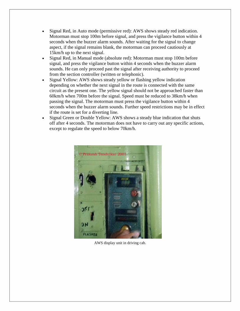
Fig. 3: Schematic of TPWS setup on the approach to a stop signal. The Arming Loop
switches on a timer and the Trigger Loop assesses the time elapsed to determine the
speed of the train. If the time is too short, showing the speed is too high, the trigger will
activate the train brakes.
The idea behind TPWS is that, if a train approaches a stop signal showing a danger aspect
at too high a speed to enable it to stop at the signal, it will be forced to stop, regardless of
any action (or inaction) by the driver. The equipment is arranged as shown left.
For each signal equipped with TPWS, two pairs of electronic loops are placed between
the rails, one pair at the signal itself, the other pair some 200 to 450 metres on the
approach side of the signal. Each pair consists of, first an arming loop and secondly, a
trigger loop. The loops are activated if the signal is
showing a stop aspect.
The pair of approach loops first met by the train at 400 to
200 metres before the signal, are set between 4 and 36
metres apart. When the train passes over the arming loop,
an on-board timer is switched on to detect the elapsed
time while the train passes the distance between the
arming loop and the trigger loop. This time period
provides a speed test. If the test indicates the train is travelling too fast, a full brake
application will be initiated. In case the train passes the speed test successfully at the first
pair of loops but then fails to stop at the signal, the second set of loops at the signal will
cause a brake application. In this case, both loops are together (see photo - right) so that,
if a train passes over them, the time elapsed will be so short that the brake application
will be initiated at any speed.
What TPWS Does
TPWS has certain features which allow it to provide an additional level of safety over the
existing AWS system but it has certain limitations and does not provide the absolute
safety of a full Automatic Train Protection (ATP) system. What TPWS does is reduce
the speed at which a train approaches a stop signal if the driver fails to get the speed of
the train under control to allow him to stop at the signal. If the approach speed is too fast,
TPWS will apply a full brake but the train may still overrun the signal. Fortunately, since
the train is already braking and there is usually a "cushion" of 200 yards (183 metres)
between the signal and the block it is protecting, there will be a much reduced risk of
damage (human and propertywise) if the train hits anything. With a possible total
distance of 2000 feet (about 600 m) between the brake initiation and the block entrance,
trains "hitting" the first loops at up to 120 km/h (75mph) could be stopped safely.
TPWS is also provided at many (about 3000)Permanent Speed Restrictions (PSRs) to
ensure that a train does not pass through a restricted section of line (say one with a sharp
curve) at too high a speed. However, there have been a number of issues related to the
use of TPWS in these cases. Drivers have complainted that, although they were
approaching the PSR at a speed which would allow the train to run at the correct speed
within the restriction, they still got stopped by the TPWS "speed trap". This has led to
some vigorus discussions between Network Rail, the train operating companies and the
HSE.
An add-on to TPWS, called TPWS+ is provided at certain signals where train speeds are
above 100 mph or 160km/h.
What TPWS Does Not Do
The safety effects of TPWS are limited by the fact that it is provided only for stop signals
and that it cannot have any effect at caution signals. This means that there is a range of
speeds at the higher level which will be excluded from full protection. In spite of this, it
is suggested in published data that 60% of accidents due to SPADs will be prevented by
the installation of TPWS at critical locations. This is achieved, it is said, at 10% of the
installation costs of a full ATP system.
TPWS does not replace the existing AWS system. AWS is retained, so the driver will
still get the warnings advising him of adverse signals. The TPWS equipment is designed
to interface with the existing on-board wiring of trains so that it can be fitted quickly.

ATP (Automatic Train Protection) or TPWS
An increasing number of railways around the world are provided with ATP. ATP
provides a either a continuous or regular update of speed monitoring for each train and
causes the brakes to apply if the driver fails to bring the speed within the required
profile. There are various versions of ATP,. ATP is popular on metros because of the
very dense train services provided and because many run for long distances in tunnels.
New, or newly upgraded high speed railways also have ATP.
The main reason why existing railways have been slow to introduce ATP is because of
the costs and because it is difficult to allow for the variable braking capabilities of
different types of trains, in particular, freight trains. The varying size and braking
abilities of freight trains means that data input for the on-board ATP computer has to be
manual. Railway administrations have been reluctant to invest large sums of money in a
safety system which, because of the possibility of manual input error, does not offer a
total "vital" safety coverage. For the UK, the high price of full ATP has caused it to be
rejected as the system-wide standard signalling safety system, so TPWS has been adopted
as the nearest suitable and more cost-effective alternative.
Pilot Project of TPWS on IR
1. Chennai –Gummiidiipudii- 50 km
2. Delhi-Agra -168 km
ERTMS
For European main line railways, the required form of train protection on those routes
intended for interoperable services (the TEN routes) will be based on the architecture of
ERTMS, the European Rail Traffic Management System. The signalling part of ERTMS
is called ETCS - European Train Control System. The system has been developed across
Europe and installed on selected routes in a number of countries. In the UK, a trial
version has been installed on the Cambrian route in Wales and the first section from
Pwllheli to Harlech was commissioned on the 28th October 2010. A useful description
of the trial installation has been published by the Rail Engineer magazine here. The
ERTMS website has a description of the basic technical structure and operation.

ACD
3
ACD is computerized equipment comprising of Global Positioning System
Digital Radio Modem Central Processing Unit Interfaces to Auto-- Braking Unit/ digital
tachometer/station signaling equipment fitted on locomotives, guard vans, stations and
level crossing gates. ACDs derive their location, speed and direction through Global
Positioning System (GPS) and work on Angular Deviation Count principle.
UHF Data Radio Modem I R GPS Receiver Working of “on-board” ACDs Take inputs
from satellites, communicate with each other and have intelligence to act to avoid
collision.
All ACDs communicate through digital radio with a range of minimum 3 km and indicate
to each other their exact location Loco ACDs apply automatic braking incase of collision
like situation

WORKING COMPONENTS OF ACD
The system comprises of:
GLOBAL POSITIONING SYSTEM RECEIVER
This gives latitude and speed of the train and picks up signals from the satellite and
submit the same to the Command and control unit. The antenna of the GPS receiver is
fitted on the top pf the locomotive.
COMMAND AND CONTROL UNIT
This is an intelligent component which is capable of decision making. It takes the input
from the GPS Receiver and gives output commands for audio visual and action signals.
RADIO TRANS RECEIVER
It is a limited range (3km) wireless data communication system for two devices to
exchange information and respond.
The ACDs on the locomotives as well as those provided at the level crossing gates
exchange their identification details through digitally coded packets when they come in
the radio contact with each other.
DATA ENTRY PAD
It is a user friendly interface, which helps the driver to feed data at the beginning of the
journey, like train no., direction of travel.

MESSAGE DISPLAY
This unit is used to display the signal condition to the driver. If the driver fails to respond
within 20 seconds then the braking unit applies the brakes bringing the train to a stop
irrespective of the fact that the track is clear or has danger.
Centralized traffic control
Centralized traffic control (CTC) is a signalling system used by railroads. The system
consists of a centralized train dispatcher's office that controls railroad switches in the
CTC territory and the signals that railroad engineers must obey in order to keep the traffic
moving safely and smoothly across the railroad. In the dispatcher's office is a graphical
depiction of the railroad on which the dispatcher can keep track of trains' locations across
the territory that the dispatcher controls. Larger railroads may have multiple dispatcher's
offices and even multiple dispatchers for each operating division.
Development and technology
Centralized traffic control (CTC) is an original development of the General Railway
Signal company. Its first installation in 1927 was on a 40-mile stretch of the New York
Central Railroad between Stanley and Berwick Ohio, with the CTC control machine
located at Fostoria, Ohio.
CTC was designed to enable the train dispatcher to control train movements directly,
bypassing local operators and eliminating written train orders. Instead, the train
dispatcher could directly see the trains' locations and efficiently control the train's
movements by displaying signals and controlling switches. It was also designed to
enhance safety by detecting track occupancy and automatically preventing trains from
entering signal blocks already occupied by other trains (see interlocking).

The basic component of a CTC system is detecting track condition and occupancy. The
track at either end of the signal block is electrically insulated, and within the block a
small electrical current passes through the track. When a train passes a signal and enters a
block, the metal wheels and axle of the train short-circuit the current, which causes a
relay associated with the track circuit to itself become de-energized (see track circuit and
rail circuits). Additionally, any fault in the rail or failure in the signal system, such as a
broken rail, a cut wire, or a power failure, will cause the relay to de-energize. When this
relay is de-energized, the system understands the track to be occupied or damaged, and
the signals show it as such to prevent a train from proceeding and encountering harm.
Signals and signal blocks
The most prominent feature of CTC is its signals. Signals govern movement over the
section of track, or signal block, between that signal and the following signal.
When calculating the size of the blocks and, therefore, the spacing between the signals,
the following has to be taken into account:
Track speed (the maximum speed the train is allowed to travel)
Gradient (to compensate for the assistance or otherwise afforded to deceleration)
The braking characteristics of the train(s) that travel on that line
Sighting (the ability of the engineer to see the signal)
Reaction time (of the engineer)
A signal is placed where signal blocks meet. Separate signals are placed for trains
traveling in opposite directions. Signals are generally placed on the right side of the track;
however, opposing signals may both be mounted on the same signal mast in opposite
directions or may be located on an overhead support system.
These signals are one of two types: an absolute signal, which is directly controlled by the
train dispatcher and is located at a control point, or an intermediate signal, which is
automatically controlled by the conditions of the track in that signal's block and by the
condition of the following signal. Train dispatchers cannot directly control intermediate
signals.
Signals have aspects and indications. The aspect is the visual appearance of the signal;
the indication is the meaning.

Train Management System
TMS display unit for Chief Loco Inspector
Introduction
Train Management System (TMS) is a system implemented by Western Railway, and
being implemented now by Central Railway, for integrated management and monitoring
of suburban train movements and signalling, as well as planning train routes, diversions,
and introduction or withdrawal of rakes in service. CR's TMS covers the major section

from CST Mumbai to Kalyan, with four additional minor sections: Ambivli (Igatpuri
side), Ambarnath (towards Pune beyond Kalyan), Bhiwandi Road on Vasai side beyond
Dombivli, and Dativli Chord Cabin beyond Diva on Panvel side. Implementation is still
in progress and is expected to be completed by 2008 or so.
Overview of TMS Working
The description here is mainly based on the ongoing implementation of CR's TMS. WR's
existing TMS is very similar, although somewhat older. The TMS system covers all train
movements in the Mumbai suburban sections of CR, including slow and fast EMUs, as
well as the Mail/Express corridors. Signalling and route interlocking information (from
signals, points, track circuits, route settings, etc., at various stations) is collected and fed
into the TMS system. Train identification information is also collected from each of the
train origination stations. The TMS system processes all this information and provides an
integrated real-time display and status indications of train positions and movements as
well as signals and route interlocking status. TMS management functions use this
integrated data to decide on induction and withdrawal of rakes, diversion of trains,
planning reversal of rakes, and so on. Control information from TMS is fed to route relay
interlocking at several locations to allow remote activation of points and signals and set
routes for trains. Within the CSTM station and yard facilities, there are also facilities for
automatically setting routes. Information from the TMS is also fed to the PA systems at
various stations for real-time updates on train status. In addition, reporting functionality
to generate punctuality reports, rake and crew links, train graphs, and unusual occurrence
reports is included.
The overall TMS display panel, known as the 'Mimic Indication Panel', is designed to
present detailed status of the system at a glance. Station layouts are shown for all stations
of interest, including all running lines and optionally the shunting lines of the stationData
communications are carried out over fibre-optic networks available between all the
stations from CSTM to Kalyan. TMS display panels are usually available with the Asst.
Station Masters and other station officials at various stations, and at the section
controllers' traction controllers' offices. TMS data input systems are installed in each
EMU driving cab as well.
COMPONENTS
Train Identification
This information is based on WR practice today; CR's TMS will use a very similar
system for identifying each rake and its trips. Each rake has a unique rake unit number
assigned to it. This is entered at the TMS input unit of the driving cab of the rake, and is
broadcast from an antenna mounted on the driving cab. This allows the position of every
rake to be known to the TMS system. Every EMU is also assigned a unique train number
when it is in service. This number (usually one or two alphanumeric characters, e.g.,
'AR') is assigned (and entered manually into the TMS system) when the rake leaves the
crashed, and also noted at the end of the day when the rake is stabled. Each EMU also
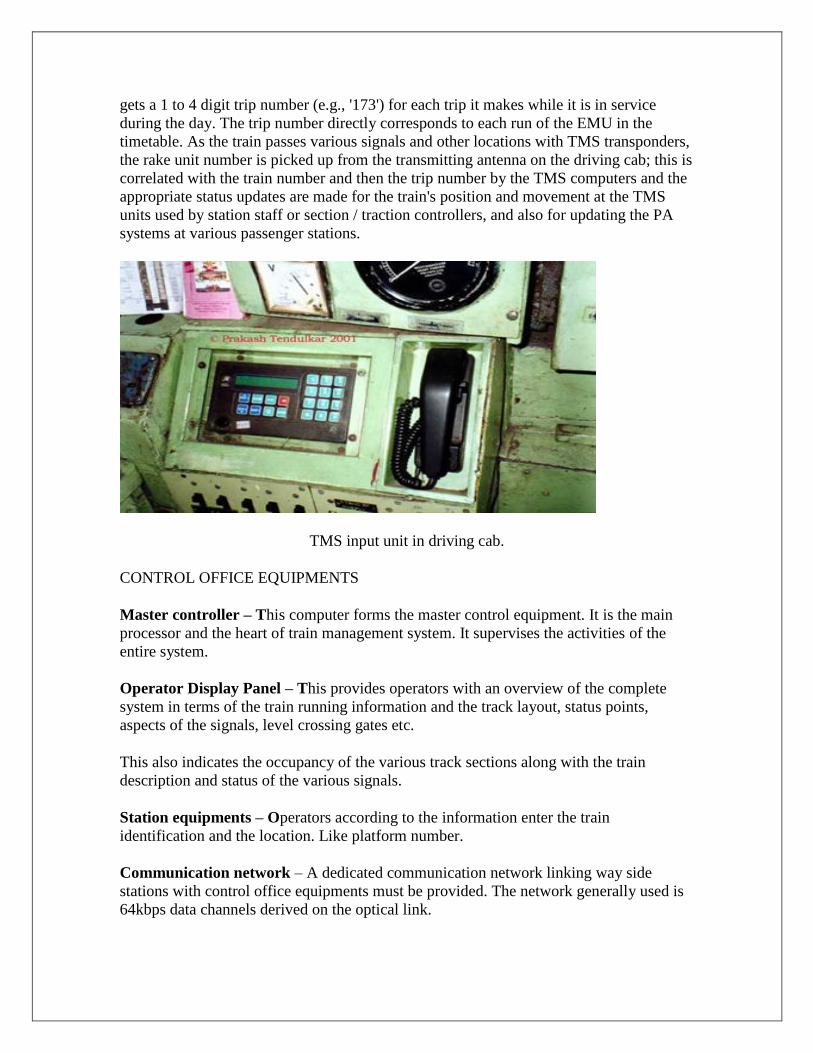
gets a 1 to 4 digit trip number (e.g., '173') for each trip it makes while it is in service
during the day. The trip number directly corresponds to each run of the EMU in the
timetable. As the train passes various signals and other locations with TMS transponders,
the rake unit number is picked up from the transmitting antenna on the driving cab; this is
correlated with the train number and then the trip number by the TMS computers and the
appropriate status updates are made for the train's position and movement at the TMS
units used by station staff or section / traction controllers, and also for updating the PA
systems at various passenger stations.
TMS input unit in driving cab.
CONTROL OFFICE EQUIPMENTS
Master controller – This computer forms the master control equipment. It is the main
processor and the heart of train management system. It supervises the activities of the
entire system.
Operator Display Panel – This provides operators with an overview of the complete
system in terms of the train running information and the track layout, status points,
aspects of the signals, level crossing gates etc.
This also indicates the occupancy of the various track sections along with the train
description and status of the various signals.
Station equipments – Operators according to the information enter the train
identification and the location. Like platform number.
Communication network – A dedicated communication network linking way side
stations with control office equipments must be provided. The network generally used is
64kbps data channels derived on the optical link.

Passenger Display and announcement system – On the basis of the information
available the monitors available on the stations display the expected arrivals of the next
two trains on each line. TMS system is also interfaced with the computerized
announcement system for the announcement of the information.
TMS display unit showing status of running trains.
In-cab signaling methods used by IR
Cab signaling is a railroad safety system that communicates track status information to
the train cab (driving position), where the engineer or driver can see the information. The
simplest systems display the trackside signal aspect (typically, green, yellow or red,
indicating whether it is safe to proceed or not), while more sophisticated systems also
display allowable speed, location of nearby trains, and dynamic information about the
track ahead. In modern systems, a speed enforcement system usually overlays on top of
the cab signalling system to warn the driver of dangerous conditions, and to automatically
apply the brakes and bring the train to a stop if the driver ignores the dangerous
condition. These systems range from simple coded track circuits to transponders(A
receiver-transmitter that will generate a reply signal upon proper electronic interrogation)
that communicate with the cab, to communication-based train control (ATP: Automatic
Train Protection;
- ATO: Automatic Train Operation;
- ATS: Automatic Train Supervision. systems.)
Some models have in-cab AWS / ATS (auxiliary warning system, automatic train stop).
AWS provides prior in-cab notification of distant or home signals that are displaying
danger or 'on'. ATS provides for a locomotive to be brought to a halt in case it overshoots
an 'on' signal that it should not have.
This has been tried out on the Mughalsarai-Howrah section (ER) but is not in wide use
although it was installed in the 1980s. (Pilferage of the track equipment is said to have
been one reason for slow adoption by the railways.) Some Mumbai-area suburban EMU
routes of WR and CR have ATS and AWS systems (WR had AWS from the 1980s, while
CR got it more recently, in 2000).
If a signal at Caution is passed at above 25km/h, a buzzer sounds in the cabin and the
motorman has to respond within 15 seconds to avoid application of the emergency
brakes. The system also halts the EMU rake if a signal at danger is passed. The lineside
transmitter for this is placed in between the rails a short distance before the signal, and
the receiver for this is placed on the leading truck of the loco. CR EMUs do not have this
system [7/00] and run without its benefit on WR tracks.
AWS systems usually work by means of electromagnets placed on the track that are
activated by the signal aspects and whose magnetic fields are sensed by the AWS sensor
mounted on the loco. A variation of AWS is being tried out [6/02] on the Delhi-Mathura
section where instead of using magnetic sensors a radio signal is used to activate the
buzzer or other alerting device for the driver.
A system of loco identification and automatic proximity alerts has been proposed for the
Konkan Railway. In this scheme, each loco would carry a beacon that transmitted its
identification, including the train number, direction, etc. Ground-based receivers would
pick up the beacon signals and relay the information to traffic control centres. Also, if
there were other locos within a short distance (2km?) with the same beacon system, an
alert would sound in the loco cab. This same system (or a similar one?) is also to be
introduced on NFR.

Some locos have a transceiver that is supposed to alert the driver of a derailment or other
problem ahead. Very few locos seem to be equipped with this. A version of ATP using
Siemens ZUB equipment has been deployed in portions of the Calcutta and Bombay
suburban systems.
Mobile Trunk Radio Communications (MTRC) is used on some sections (Bhusawal -
Itarsi, Itarsi - Nagpur, Nagpur - Durg). This is an older analog system dating to the 1980s,
which allows the Traction Loco Controller to talk by radio to train crew that is carrying a
receiver with them in the locomotive cab. Digital versions of MTRC have been
considered and are slated for trials soon [2/05].
Methods of communication with train crew are used on IR
Handheld radios (walkie talkie sets) are widely used now (since the late 1990s) by train
crew, yard crew, etc.). Some stations have transmitters allowing them to broadcast to all
walkie talkies in the vicinity. Often, because of their higher power they are able to
transmit to walkie talkie sets carried by crew that are farther away than the distance the
walkie talkies can normally operate within, so that they cannot receive any messages in
the reverse direction in such cases!
The Rajdhani Expresses still use a primitive though reliable form of communication. A
pair of wires are connected to a telephone socket on the end of the first Rajdhani coach,
usually a generator van. This telephone line then goes through the entire rake to the last
coach where the guard has a telephone instrument. The driver also has a portable
instrument which he plugs into this wire and communication between the guard and
driver becomes possible even if the walkie talkies cannot function for some reason.
Data logger system
With increase in traffic and system modernization, monitoring and maintenance of
signaling equipments has become a tedious job. Thus data loggers were introduced so
that the equipment failures may be predicted I advance and corrective measures may be
taken.
Many areas have data logging equipment for each piece of signal equipment, which
records information on the functioning of the signal and sends it to a computer at a
central point (usually the division headquarters) where reports can be generated and
alarms raised for various kinds of malfunctions (power failure, signal passed at danger,
train entering without line clear, signal lamp failure, loose packing of points, etc.). A
typical data logger used in such a system monitors all signal equipment and track circuits
5-50 times a second and signal power supplies every second.

SYSTEM DESCRIPTION
All the data loggers are connected in series by modems and the front end processor at
control room is connected to the central computer through RS 232 cable.
The system may be broadly fragmented as:
1) Data logger – These are built around MOTOROLA 68000 microprocessor and may
perform operations like data scan, data transmission, diagnostics etc. The data loggers are
connected with required number of digital and analog inputs. 4096 digital and 64 analog
inputs. Digital inputs are scanned for every 20 milliseconds and the Analog inputs are
scanned for every 16 seconds. There is provided an LCD screen and keyboard provided
in the front panel of the datalogger which helps in man machine interface. Setting of
time, Latest status display, Analog voltage display and printer are the other options
available.
2) Front end processor – This is also built around 68000 microprocessor. The main
function of the FEP is to receive the data from the dataloggers and to store it in memory.
This feature helps the user to use the computer for any other purpose and during that the
data transfer from the data loggers is not affected. It has two serial ports of which one is
connected to the computer and the second is connected to the first data logger in the
network.
3) Failure analysis system – This consists of the computer which stores all the reports of
the events that had taken place for the selected date and time. Thus the failures may be
detected and hence preventive measures are taken.
CATECHISM FOR SIGNALLING AND TELECOMMUNICATION INSTALLATIONS FOR 25 KV 50 HZ, SINGLE PHASE AC ELECTRIFIED SECTIONS
SECTION-I - SIGNALS :
1. Are the signals located in accordance with the approved instructions as per Manual of Instructions for installation of Signalling and Telecommunications Equipment in 25 KV, 50 Hz AC electrified sections?
Have the protective iron screens as required for
2. signals/fittings within 2m of live conductor/parts been provided and earthed?
3. Where it is not possible to provide protective iron screens, has a caution board been provided on the signal posts in accordance with the approved instructions?
4. Has the “Signal Sighting Committee” certified that the driver’s view of the signal is clear?
5. Have only multi aspect signals been used in colour light signalling area?
6. Is the AC power supply arrangement for the colour light signals of a type approved for Railway Electrified areas?
SECTION-II - POINTS :
Have the rodding transmission of points and other apparatus been insulated as per the approved instructions?
SECTION-III - ELECTRICAL SIGNALLING EQUIPMENT:
1. Does the design of signalling equipment and the circuits used in Railway Electrified areas provide for a safety factor of 1.5 against AC interference.
2. Has it been ensured that the signalling equipment not suitable for Railway Electrified areas on external circuits like banner type indicators, Luminous indicators, telephone type relays, electrical lever locks, rotary key transmitter, DC neutral polar relays, 250 ohms DC neutral line relays and door coils of IRS block Instrument etc. have not been used?
3. Has it been ensured that all stick relay have at least 4 front and 4 back contacts and their pick up transfer time is not less than 300 milli seconds?
SECTION-IV - CABLING AND WIRING OF CIRCUITS:
1. Have all telephone circuits, except cabin to cabin and cabin to ASM circuits, which may be retained on signalling cable, been transferred to separate underground telecommunication cable?
2. Have all overhead wire circuits been shifted or cabled as per the approved instructions?
3. Has it been checked that the voltages induced due to parallelism in the telecommunication cable under normal and short circuit conditions are within safe limits (limits specified by the Consulting Committee of International Telegraph and Telephones)?
4. Has it been ensured that the earth return circuits are not retained and have been replaced by metallic return circuits except the block circuits?
5. Has the principle of double cutting been used for all external-signalling circuits?

6. Have the external circuits and batteries been isolated from internal circuits and batteries?
7. Has it been ensured that the induced voltages in the length of inter cabin telephone circuits in signalling cables does not exceed 60 V?
SECTION-V - BATTERIES:
1. Has it been ensured that power supply for internal and external circuits and for each block instrument are isolated? Has it been ensured that the battery for signalling
2. Equipment is separate from the battery for telecommunication equipment?
SECTION-VI - EARTHING:
1. Have the lever frames and other equipment been earthed in accordance with the approved instructions?
2. Has it been checked that no earthling pipe is less than 3 m away from any other earthling pipe?
3. Has it been tested that the earth resistance does not exceed 10 ohms for the signalling equipment and 1 ohm for telecommunication copper cable earth?
4. Has the screening of the telecommunication cable terminated at the sectionalising points and repeater stations been earthed in accordance with approved instructions?
SECTION-VII - TRACK CIRCUITS:
1. Has it been ensured that track circuits are of approved type?
2. Have measurements of DC tray currents been taken before installations of DC single rail track circuits and whether these are within permissible limits?
3. Has the longitudinal and transverse bonding in track circuited areas been provided as per the approved instructions?
4. Have the DC single rail track circuits of closed type been installed in accordance with the approved instructions?
5. Have the protective measures like surge discharges (intervals off discharge) been provided on track circuits, where required, as per the approved instructions?
SECTION-VIII - EMERGENCY CONTROL:
Have emergency control telephone post been provided at correct regular intervals along the track in electrified areas as per the approved instructions?
SECTION-IX - BLOCK INSTRUMENTS:
1. Are the block instruments installed of a type approved for use in AC electrified sections?
2. Have block filters for single and double line block instruments been provided in accordance with the approved instructions?
3. Are the filter units of an approved design?
4. Have the line terminals of block filters been painted red to caution the maintenance staff against high voltages?
5. Where a block section falls between an electrified and non-electrified section, has it been

ensured that block filters have been provided for block instruments at either ends of such block section?
6. Have the block telephones been provided on a separate pair of conductors in accordance with the approved instructions?
7. Have the block circuits been provided on underground cables as per the approved instructions?
8. Have position polarised relays of SGE block instruments been provided in accordance with the approved instructions?
9. Have the block release and advance starter control of block instrument been provided in accordance with the approved circuit?
Has it been ensured that the circuits from a non electrified
10. section approaching and electrified section and vice versa been cabled for a length of 1 km beyond the electrified sections.
SECTION-X - GENERAL SAFETY:
1. Has the chart on method of treating electric shock been displayed in cabins and relay rooms, etc.?
2. Has the rubber matting been provided in relay rooms, repeater stations and cable huts etc. as per the approved instructions?
3. Have special instructions been issued to the personnel that the accessible parts of the installation and apparatus in the repeater stations and cable huts, connected to the telecom cable are likely to attain an induced voltage of 150 V AC under 5 normal working conditions and have such parts of installation and apparatus suitably marked to indicate this?
4. Have the metallic cabinets/covers/frames of telecommunication equipments provided in railway electrified areas been earthed properly?
5. Are the protective devices installed on telephones provided at grid stations, 25 KV sub stations and switching posts as per the approved instructions?
6. Are the tools used by maintenance staff properly insulated?
Fiber-optic communication
Fiber-optic communication is a method of transmitting information from one place to
another by sending pulses of light through an optical fiber. The light forms an
electromagnetic carrier wave that is modulated to carry information. First developed in
the 1970s, fiber-optic communication systems have revolutionized the
telecommunications industry and have played a major role in the advent of the
Information Age. Because of its advantages over electrical transmission, optical fibers
have largely replaced copper wire communications in core networks in the developed
world.
The process of communicating using fiber-optics involves the following basic steps:
Creating the optical signal involving the use of a transmitter, relaying the signal along the
fiber, ensuring that the signal does not become too distorted or weak, receiving the
optical signal, and converting it into an electrical signal

Indian Railways have seamless Right of Way along 63,000 KM of Railway Track passing
through 7000 stations across the country. The stations in major cities are located in
central business districts. Indian Railways already had established a strong Telecom
Network to meet its communication requirements. With the formation of RailTel
Corporation, Indian Railways' Right of Way and OFC assets have been transferred to
RailTel. Presently, about 32500 KM of OFC has already been laid and over 29500 KM
has been commissioned. Works on another 10620 KM are in various stage of completion.
PRS (Passenger Reservation System)
Computerized passenger reservation system is a most useful facility, which
enhance the image of Indian railways in public.
It is an efficient and dynamic network of reservation all over the India.
Initially it is installed is Delhi by criss and for western and central railways a
common super computer is installed, and the trains of both railways are programmed on
this computer.
Terminals of different locations connected to this main super computer with the
communication link through OFC; UHF; MW, on 4 wire/2wire analog speech channel;
digital 64Kbps channels with the help of Mux
In PRS, there is only one set of computers in which all the information regarding
the train coaches reservation, fare, status are available; and terminals can access these
computers from remote location for registration, inquiry of reservation and data for
printing the chart and the ticket. And it also deals the accounting of each terminal.
The terminals access through mux. & Modems. And connectivity will be
established through Rly. UHF, MW, Digital MW, DOT Lines, OFC. Etc.
At present there are 5 Main computer frame i.e. CSTM, DLI, HWH, DS, MAS,
and all computers are interconnected to each other with 64Kbps through lease line
modem and each set of computers are having the terminals spreading over their
jurisdiction. So any of the terminal access any of the train of Indian railway originated
from any of the place. And book their ticket with reservation.
Normally the standard modem employed for PRS usage for transmitting data at
the speed of 4800Bps, but now a day the speed is improved upto 14400Bps. So the
system work faster and efficient.
CSTM Main Frame Computer: -
The PRS main frame computer is installed at CSTM at passenger reservation
center .It consist ‘4’ servers connected to each other in cyclic order or bus connectivity
through Ethernet cable, and all the servers share a common stored memory i.e. a group of
70/80 hard disk installed in rack. But they can access any of the hard disk for retrieving
and writing the information.
The main server is connected to slave servers of company DCE (digital electric
company) which provide ID and prompt to each terminal. And each slave server can
accommodate 16 or 32 ports or terminal. These servers are connected to main frame
computers through Ether net cable by ‘T’ connections or through multiplexer made by
DELNI Company, Which can accommodate 8 or 16 DCE servers. The total numbers of
slave server i.e. DCE in CSTM are about 200 0f 16 or 32 ports of speed 4800bps.

The DCE terminal can be connected to node or terminal directly through RJ11
connector if the distance is only 15 meters. And if distance is more than it should be
connect through LNA. But if the location is at remote place than it is connected through
mux-modem. For that 8 or 16 ports digital or analog mux can be used to use a common
media channel through modem with a speed of 4800/9600/14400 BPS depend upon the
channel quality and type of channel. If use analog than the SQ should be 9 and SNR
should be 39 of company DCM or CODEC, but if digital system is used than CYGNUS
mux-modems are used. Here a connectivity of Ahmedabad is shown here, where at
CSTM end the server ports are multiplex in CYGNUS -516 multiplexer which can
accommodate 8/16 terminals along with 2 voice ports and the output is a composite
signal of 14.4kbps, and these composite signals of about 12 muxs are again multiplex by
another multiplexer of CYGNUS 731 make and the output of it is 2 channels of 64kbps
and 9.6kbps which can be transmitted through media i.e. the 64 KBPS channel is
transmitted through railway and 9.6 KBPS is through DOT circuit. And the network is as
below.
Now a day PRS being a very popular passenger amenity, So that S&T is required
to maintain its data & analogs channel. Very efficiently with very close tolerance, and a
slight interruption result in stoppage of reservation
Freight Operation Information System
The freight operation information system FOIS is a project for Indian railway for
operating management of wagon, empty wagon, loco and crew movement control. This
system has two major component i.e. computer segment and main telecomm network
segment. For the above management a software program is developed for the CN, yard
and terminal management. The software is TRACS.
The TRACS software is a program which suit Indian railway requirement and for
best effort for operation. IIT committee has reviewed and provides suggestions for future
course of action.
The overall complete architecture has been drawn jointly by CRIS and CMC
based on Indian railway organization’s present and future requirements.
The functions of freight operation on railway constitute capturing demand, supply
of rakes/wagon, planning, controlling the movement and loading and unloading of
freight.
There are two type of freight operation are maintained in railways. And for these
two types of operation two modules are formed. They are rake monitoring system
(RMS) to take care operating functions like rake formation, tracking of consign-ment,
individual wagons, locomotives and train. The other module is terminal management
system (TMS) to take care of commercial functions. Both the modules are implemented
in railways quite successfully and received a positive response.
SYSTEM ARCHITECTURE –
Intelligent terminal are placed at field location for data from place of activity like
control office, yard, goods sheds, C&W depot, loco sheds and connected to the
identified application server through reliable communication network.

Application servers are placed at central location (CRIS) for processing within
its own operation jurisdiction and provide management report at zonal level and
also made connection to central server for global level transaction.
Central server provide management reports to Railway Board and make
document file for all global data including master file as provided for global
service.
DATA COMMUNICATION REQUIREMENT –
FOIS has real time transaction processing with strict time relation ship between
various transactions. The data fed to the particular location is available for next
location. At this location changes can be made if need, which are reflected at
central data base in real time basis. This process is continuous at all location
along the movement of the train. The data is fed from reporting location to
central location data base using an interactive session between client and server.
The client software is GUI based. A 64 Kbps and width is used for connectivity
between reporting location to central server.
The response time for various transaction are –
Enquires – 4 to 12 second.
Input update – 15 to 25 second
Solicited report – in minutes.
TRACS was suppose to take 2 to 6 sec. To answer for enquiries, average time for
response to update – 10sec. And balance time for transaction delay.
High speed connectivity is required between application servers at CRIS.
The requirement of reporting location can very with respect to number of terminal
which need to be connected to central data base server.
Voice communication –
o Voice link between central location to zonal location
o Voice link between zonal location to reporting location
Network – the following type of network are used for connectivity between central
location to various location.
Use of terrestrial circuits of required capacity from DOT where railways circuits
are not available.
Each location should have atleast two alternate path on diversified media.
ISDN based dialup circuit are to be provided as alternate path as an interim
arrangement.
Location where above link are not available. V-SAT is used.
Number of router hops from divisional location and reporting location to central
server is limited to maximum 3 and 4 respectively.
NETWORK TOPOLOGY –
A star based network topology is used in order to provide alternate path. A mash
has been created with in zone. So that every zonal location on has at least two path for
CRIS. Each zonal head quarter has been connected to CRIS on high bandwidth pipes of
128Kbps and /or upgrade up-to 2Mbps.
WIDE AREA NETWORK – WAN –
Band width requirement for each terminal location is 64 kbps. Every route has
two routes to CRIS. Every zone has at least two nodal locations from where it is
connected to CRIS. These nodal location links are thicker pipes of at least 128kbps and
can be upgrade to 2mbps.
Each zone has been configuring as a separate routing zone and not
connected to nearest / adjacent zone. This has been done to ensure scalability.
The alternate path has been provided on the same media. The local lead from
nearest microwave / OFC is connected. Whenever local lead fails, it results as shown as
the failure of both primary and alternate link. So to avoid the failure media diversity is
preferred.
If DOT refuses to provide lease line due to non availability of local lead, then
ISDN connectivity has been provided only for temporary basis in dialup link.
Yard of important location has been provided with WAN. There are three way to
provide the connectivity form CRIS.
64kbps link on copper cable by providing a router at yard.
Up to 2mbps on copper cable by providing a router at yard.
Wireless LAN extender is available in market which is costly and offers a speed
up to 2mbps.
On V-SAT – now a days TDM / TDMA base VSAT connectivity is used to
connect those location where railway / DOT 64 kbps line are not available. In this
case a dedicated Hub is installed near the central server location. So the
propagation is restricted to single hop and connectivity between central servers to
VSAT hub is through a high speed LAN.
The frequency band of VSAT (c, extended C, Ku) transponder is used.
Provision of FOIS connections at the residences of traffic officials.
The router provided at the LAN of field location have spare ports, these ports has
been configure as dial up asynchronous ports and have been connected to railway
telephone exchange through dialup modem. Personal computers provided at residence
of concerned officer can be dialing the number of modem and access the FOIS
network with his own password..
LOCAL AREA NETWORK –
AT CRIS –
The central location of CRIS where all the server, distributor routes and system/
network administrator are located, a high speed LAN of 100Mbps is installed. The LAN
of development servers and training servers has been segregated from main LAN. So they
do not share the media of on line traffic density. The distributor router has been provided
on a 10mbps LAN, which can be upgrade to 100mbps. These routers are provided hot
standby arrangements. Now a day CRIS routers have a combination of 2mbps ports,
64kbps ports and ISKN ports.
AT FIELD LOCATOIN –
All location are multi terminal locations. A small 10 base T LAN has been setup
at each location. The software used for terminal location is Enterprise – wide
management system (EMS) which is comprises of several components like network
management, software distribution, remote control of desktops, asset/ inventory
management. FOIS management domain is 2-tier architecture. The central tier at CRIS
will have a global view and other at each zone. These will monitor all the communication
link and data communication devices in their domain proactively.

Software distribution and version control – this is required for distribution of
RMS application software and upgrades to all client PCs. This is allow to
distribution of software automatically though customized distribution schedules
during peak hours. This distribution will package, deliver, install, configure,
activate and de-install application software remotely without the need for manual
intervention.
ASSET / INVENTORY MANAGEMENT MODULE – It shall enable efficient
control of all it resources i.e. detailed information on each application and end
user, the hardware and software configuration of all desktops and servers, and
location of all network resources. It also provides the configuration management
to centrally administrate configuration files. It shall also provide for a policy
based application software usage.
REMOTE CONTROL – In case of RMS, the end user is illiterate computer. So
the needs of a remote control function-software which enables complete control
of the remote desktop centrally. This module also be deployed both at central and
zonal location.
There are so many functions like help desk module, network management, server
/ OS management, data base management, storage management etc.
THE VOICE REQUIREMENT –
The requirement of voice circuits is for initial phase for installation, up to a
staged till application stabilizes. This requirement can be catered to in one of the
following way:
A dedicated channel between the desired location on the railways network
wherever spare capacity is available on railway network.
In area where railway STD network has been upgraded, a railway phone with
STD can be serving the purpose.
On the location where arrangement is not available, the routers shall have
voice over IP facility but the bandwidth will be kept to the minimum so that it
just gives toll quality voice.
APPLICATION SERVER REGION 1

IVRS
CMC, Kolkata has developed an Interactive Voice Response System to cater to the
various requirements of Computer Telephony world.
The main features of IVRS developed by CMC are following:-
1. Multitasking and multithreading facility leading to simultaneous handling of 4
channels 32 analog channels or more than 32 digital channels.
2. Modular and scalable design allows increasing the number of channels or services
without changing the basic IVR software.
3. Detecting an incoming ring and automatically establishing connection in response
to the ring signal. Number of rings before picking up the call is configurable.
4. Capable of working round the clock throughout the year.
5. Dynamic, user configurable, channel specific menu of IVRS, leading to setting of
different service for different incoming lines (channels).
6. Multiple language support with user configurable channel specific language.
Number of languages used may vary from 1 to 10.
7. Incoming calls from decades dial telephone across PSTN/Railway/PBX line/cell
phone. Caller can dial in both pulse and DTMF mode with DTMF inputs to select
from IVR menu options.
CHENNAI
BUS – 100Mbps
DA
TA
BA
SE
CE
NT
RA
L S
ER
VE
R
AP
PL
ICA
TIO
N S
ER
VE
R
RE
GIO
N 1
AP
PL
ICA
TIO
N S
ER
VE
R
RE
GIO
N 1
AP
PL
ICA
TIO
N S
ER
VE
R
RE
GIO
N 1
AP
PL
ICA
TIO
N S
ER
VE
R
RE
GIO
N 1
ROUTER of 10Mbps can
be update to 100Mbps
NET
WORK
DELHI

8. Work with all type of exchanges on voice lines or trunk lines with
BSNL/MTNL/Railway communication Network and cellular phone network.
9. Support various means of Alarm indications in case of system failures, e.g.
Functional error, Error of missing certain voice message prompt, etc., and
generates error Logs.
10. Provides call statistics and customized report after call analysis viz. "Call success
Rate", "Call Failure Analysis", "Response Delay Analysis", "Service-
wise/channel specific calls", "languages selected".
11. ODBC support for accessing all kind of standard database/RDBMS.
12. Good Voice Quality supports up to 48 KHz sampling.
13. Provides additional tools for recording and editing voice files and online
deployment.
The functionality of IVRS developed for Indian Railways are following:-
1. Reservation Status Enquiry using PNR number
2. Accommodation Availability Enquiry
3. Train Arrival Departure Enquiry
4. Train Details Enquiry
5. Integration with PRS through RS-232 serial asynchronous links
6. Integration with NTES via LAN
7. Database backup and recovery
8. Network connectivity health status display
The IVRS has a big role to play in the National Train Enquiry System
National Train Enquiry System is a reliable centralized information system which
provides up-to-date and accurate information to the passengers regarding:-
Arrival/ Departure of passenger trains including Expected time of arrival (ETA)
of trains
Platform berthing of passenger trains
Journey Planning (presently SMART package)
Facilities available at stations (presently GLOBAL ENQUIRY package)
Railway Rules (presently GLOBAL ENQUIRY package).
These information’s are made available to the user through Display Boards, Interactive
Voice Response System, Public Address System, Face to Face Enquiry, CCTV and it is
proposed to make it available on the internet in the next phase. The beta version of NTES
inquiries on internet is available. The above information is collected from stations,
control offices and other database administrators. The project started as a pilot project
and was implemented in Aug. 1998. In the phase II, the software has networked all 5
servers running the NTES application. It now runs on Alpha server machine and under
UNIX using Sybase as the RDBMS. NTES phase II is successfully running at all five
PRS sites.

NTES IR has to provide the following information to passengers:
• Arrival and departure of passenger trains
• Platform berthing of passenger trains
• Facilities available at various stations ( e.g. retiring rooms)
• Railway Rules
The above information is made available to the public through:
• Display Boards
• Interactive Voice Response System (telephone enquiry)
• Automatic Announcement System
• Face to Face Enquiry counters
• TV display
The above information is available at:
• Arrival Departure Information - Control Offices
• Platform Berthing - Stations
• Other Data - Designated Database Operators
The NATIONAL TRAIN ENQUIRY SYSTEM (NTES) has the following aims
? To collect train arrival departure information from control offices
? To collect platform berthing of trains from station.
? To provide updated information of arrival departure of trains and platform berthing to
external
devices.
? To provide updated information on railway rules and facilities available through
enquiry counters
? To make above information available on internet
Key Requirements for NTES
? Open solution

? Scalable system
? Reliable
? Round the clock operations
? Online backup
? Low response time (typically < 1 sec)
? NTES will have to share the existing 64kbps/2mbps lines used by PRS. Hence we have
to keep low network load between sites.
? Use of existing communication infrastructure for connecting to external devices. This
would typically be a shared serial link at <= 4800 BPS
? Internet ready
? Text based user interface should be available through serial terminals using existing
links.
? Capability to handle high volume of enquiries.
The NTES application consists of four layers and three other functions namely
1. RDBMS
2. SERVERS
3. CLIENTS/APPLICATION GATEWAYS
4. EXTERNAL AGENTS
5. Database Administration
6. Application Management & Console Operations
7. Reports
RDBMS
• Control all database updates and queries.
• Application logic resides in RDBMS in form of triggers and stored procedures.
• Direct access to RDBMS will be only to 2,5 and 7.
SERVERS
• Handle client requests
• Multiplex database sessions
• No application logic will be coded in the servers.
• Populate the results of SQL into data structures used by the client.
• For services provided by the server a request function has been written. These functions
form the
part of the SERVER API
• The SERVER API has been designed such that:
• The client is able to use the service without knowing any TP monitor data structures.
• It is possible for client to directly access all services without any change in code.
CLIENTS
These have been defined as of two types

• Interactive
• Application gateways
The interactive client runs on a dumb terminal based client and is used by users directly
connected to NTES server.
Application gateways use the External Interface Server API and give a set of services to
clients who reside outside the NTES server and are connected to it. These are of two
types:
• TCP/IP gateways e.g. for Web
• Serial gateways e.g. for IVRS
EXTERNAL AGENTS
These reside outside the NTES server.
They use the External Interface Client API for accessing NTES services
These agents are free to access cache data in their local database.
Services is provided for bulk transfer of data for local storage in the External Interface
API.
Implementation Phases
The entire implementation of the pilot project is divided into 3 phases. They are:-
Phase–I : Scheduled and actual arrival and departure information of trains over
Interactive Voice
Response System and across the counter using C++, Middle ware Reliable Transaction
Router and Adaptive Server Enterprise Sybase RDBMS.
Phase-II : Disseminate Tourist Information, Special Trains, Railway’s Facilities and
Scheduled and actual arrival and departure information to spot trains over Internet and
SMS using HA, Web Server and RDBMS. Provide actual train running position to
Minister Of Railway’s special Cell constituted to monitor the punctuality of special
trains.
Phase – III : Build complete data base of all trains, their coaches, the kind of repair and
maintenance
they are undergoing using J2EE, Application Server Web Sphere and Browser based thin
clients.
BENEFITS
How will passengers be benefited by NTES?
The passengers
• Can Plan their Journey well in advance as complete tourist information is available
• Don’t have to wait at railway stations when either they come to board train or to receive
their kith ad kin.
• Don’t have to waste time in locating platform of train, retiring room, clock room and
other facilities
• Can easily know about catering services, circular journey tickets and fares
• Can find out about refund rules for unused tickets, special trains and holiday special
trains
• Can monitor the movement of trains in real time and punctuality of trains

• Can know about various concessions and their percentages
• Can know about reservation rules
• Can find out about break journey rules
• Can know about offences and penalties
• Can enquire about scheduled arrival and departure time of trains
• Can know about train fares
IMPORTANCE
Replication Server implementation using Sybase, The data at all the five sites is
replicated to all the other sites. The Sybase Replication Server maintains replicated data
in multiple databases. It provides clients using databases in the replication system with
local database access, thereby reducing load on the network. Each site has its own
replication server.
These replication servers communicate to the local database via connection. The
replication servers communicate amongst themselves via user defined routes. There are
two types of replication servers namely the primary replication server and the replicate
replication server. The primary Replication Server sends data to the replicate replication
server through one or more user defined routes. The user creates a replication definition
at the primary Replication Server which specifies the information (like columns) to be
replicated . The Replication Server uses a basic publish and subscribe model for
replicating the data across the network. The user creates a publication of the data that is
to be replicated to the other sites and the other sites subscribe to that publication for the
delivery of data. Changes in data as well as stored procedures can be replicated across the
network. The replication of data occurs asynchronously, that is updates to data at the
primary are transferred to replicate databases in transactions separate from the update
itself.
UNRESERVED TICKETING SYSTEM (UTS)
More than 1.2 crore Rail passengers travel in unreserved coaches and trains every day
and thus form the bulk of rail users. For this category of passengers Railways have
introduced the facility of Computerized Unreserved Ticketing System was initially
provided at 10 stations of Delhi area in the first stage as a pilot project on 15 August 2002
. Another 13 stations of Delhi area were provided with UTS counters in the second stage
on 2 nd Oct, 2002. It has since been extended in an integrated manner to more than 180
stations all over the country. UTS system has been planned to take over the Printed Card
Tickets or tickets issued by self Printing Ticket Machines gradually.

UTS will provide the facility to purchase Unreserved Ticket 3 days in advance of the date
of journey. A passenger can buy a ticket for any destination from the UTS counter for all
such destinations which are served by that station. The cancellation of tickets has also
been simplified. Passengers can cancel their tickets one day in advance of the journey
from any station provided with a UTS counter. On the day of journey, the ticket can be
cancelled from station from which the journey was to commence.
Indian Railway is constantly looking for new ideas to simplify and streamline procedures
for the convenience of passengers. In this endeavor they have introduced several path
breaking technologies on the Railway system over the years. These technical innovations
have included the computerization of reserved passenger tickets amongst several other
facilities for passengers. As we introduce new facilities on the railway system, we are
tempted to take a peek into the past. The legacy of the 150 years of railways in India is
not only filled by the memories of the steam run trains puffing over the countryside, it is
also of cardboard tickets, one for the fare and the other for reservation and of course, the
memories of sending telegrams for return reservation to the station master from where
one was to begin the return journey. With the introduction of the computerization of
reserved tickets, these memories have been relegated to the past. It is now considered to
be a basic minimum requirement to acquire confirmed reservation for traveling, at one's
convenience and proceed on a journey carrying a confirmed ticket for the return journey.
This has been achieved only in the last quarter of the last century. In addition to this
facility, unreserved tickets will continue to be available through the manual system and
the Self Printing Ticketing Machines, wherever such facilities are available. With the
introduction of this system, the Railways will also benefit in several ways. These are :
Keeping pace with the latest technology
Encouraging passengers to purchase their tickets in advance
To have online accountal of tickets sales.
To have a rational analysis of the demand of passengers on various routes in advance, so
as to augment trains as per requirement.
Advantages of Unreserved Ticketing System
Reduced queue length ,Enable advance planning of unreserved journey also
Reduced crowds at booking offices and stations, making ticket purchase more
comfortable
Allow Indian Railways to plan extra trains and coaches as per trend of sales registered in
the system. Unreserved itinerary planning possible, tickets available from any station to
any station.