Embed Size (px)
Citation preview

INDIAN OIL CORPORATION LIMITED
CHENGALPET LPG BOTTLING PLANT
RISK ANALYSIS STUDY REPORTPREPARED BY
IOCL – CHENGALPET BOTTLING PLANT RISK ANALYSIS STUDY REPORT
CONTENTS
1. Introduction 1
2. Risk Assessment and Hazard Identification 1
3. Methodology 2
3.1 General 2
3.2 Preliminary Risk Screening 3
3.3 Risk Classification and Prioritization 3
3.4 Analysis and Assessment Levels 3
3.5 Qualitative Analysis 6
3.6 Quantitative Analysis 7
4 Manufacturing process Flow chart & Description 8
4.1 Description of process 8
5. Liquefied petroleum gas (LPG) 10
6. Hazards from LPG Storage and Handling 12
6.1 Jet Fire 12
6.2 Vapour Cloud Explosion 12
6.3 Flash Fire 12
7. Hazardous conditions due to release of LPG 13
7.1 Thermal Effects 13

IOCL – CHENGALPET BOTTLING PLANT RISK ANALYSIS STUDY REPORT
7.2 Delayed Ignition and Explosion 14
8. Identification of Hazard for LPG unloading and storage and
filling 14
8.1 Categories of Hazards 14
8.2 Hazard Identification (HAZID) 15
9. Release and Outcome Scenarios 15
10. Consequence Analysis 19
10.1 Model Used For Consequence Analysis 19
10.2 Consequence Analysis For LPG Release Scenarios 19
10.3 Rupture of 18 MT Bullet Tanker 20
10.4 Rupture of 14.2 kg LPG Cylinder 24
10.5 Release of SRV of Mounded Bullets of 600 MT 28
10.6 Release of LPG from pump 30
10.7 Release of LPG From Compressor 33
10.8 Leak from LPG Transfer Line 36
10.9 Rupture of LPG Transfer Line 38
11. Failure Frequency Data Base 38
11.1 Flanges 38
11.2 Pumps Failure Frequencies 40
IOCL – CHENGALPET BOTTLING PLANT RISK ANALYSIS STUDY REPORT
11.3 Probability of Ignition 41
12. Risk Reduction Measures 42
12.1 Risk Mitigation Measures 42
12.2 Mounded Bullets 43
12.3 Maintenance Schedules 48
12.4 Electrical Hazards 48
12.5 Fire Fighting Facilities 50
12.6 Control Room 57
12.7 Safety Audit And Inspection 57
12.8 Induction And Refresher Safety Trainings 57
12.9 Emergency Response Plan 58
12.10 Mock Drill Exercises 58

IOCL – CHENGALPET BOTTLING PLANT RISK ANALYSIS STUDY REPORT
RISK ANALYSIS STUDY REPORT
1. INTRODUCTION
Industrial plants deal with materials, which are generally hazardous in nature by
virtue of their intrinsic chemical properties or their temperature or pressure of
operation or a combination of these. Fire, explosion, hazardous release or a
combination of these are the hazards associated with industrial plants. These
have resulted in the development of more comprehensive, systematic and
sophisticated methods of Safety Engineering such as Hazard Analysis and Risk
Assessment to improve upon the integrity, reliability and safety of industrial
plants.
The primary emphasis in safety engineering is to reduce risk to human life and
environment. The broad tools attempt to minimize the chances of accidents
occurring. There always exists, no matter how remote, that small probability of
a major accident occurring. If the accident involves highly hazardous materials
in sufficient large quantities, the consequences may be serious to the plant, to
surrounding areas and the populations therein.
2. RISK ASSESSMENT AND HAZARD IDENTIFICATION
Risk is defined as the unwanted consequences of a particular activity in relation
to the likelihood that this may occur. Risk assessment thus comprises of two
1

IOCL – CHENGALPET BOTTLING PLANT RISK ANALYSIS STUDY REPORT
variables, magnitude of consequences and the probability of occurrence of
accident.
The first step in risk assessment is identification of hazards. Hazard is defined
as a physical or chemical condition with the potential of accident which can
cause damage to people, property or the environment. Hazards are identified by
careful review of plant operation and nature of materials used. The various
scenarios by which an accident can occur are then determined, concurrently
study of both probability and the consequences of an accident is carried out and
finally risk assessment is made. If this risk is acceptable then the study is
complete. If the risk is unacceptable then the system must be modified and the
procedure is restarted.
3. METHODOLOGY
3.1 General
A Risk Analysis is to provide sufficient information and assessment of risks to
show that a project satisfies the risk management requirements of the proponent
company and the relevant public authorities. Within this brief, the main objective
of the PHA is to show that the residual risk levels are acceptable in relation to the
surrounding land use, and that risk will be appropriately managed. This is done by
systematically:
2

IOCL – CHENGALPET BOTTLING PLANT RISK ANALYSIS STUDY REPORT
• Identifying intrinsic hazards and abnormal operating conditions that could give
rise to hazards
• Identifying the range of safeguards
• Assessing the risks by determining the probability (likelihood) and
consequence (effects) of hazardous events for people, the surrounding land
uses and environment and
• Identifying approaches to reduce the risks by elimination, minimization and/or
incorporation of additional protective measures.
With proper application, this method should demonstrate that the plant can operate
within acceptable risk levels in relation to its surroundings.
The RA needs to be carefully and clearly documented with the assumptions and
uncertainties of final design and operation defined.
3.2 Preliminary Risk Screening
The need for a RA is determined by a preliminary risk screening of the proposed
development. The preliminary screening methodology concentrates on the storage
of specific dangerous goods classes that have the potential for significant offsite
effects. Specifically the assessment involves the identification of classes and
quantities of all dangerous goods to be used, stored or produced on site with an
indication of storage depot locations.
3

IOCL – CHENGALPET BOTTLING PLANT RISK ANALYSIS STUDY REPORT
3.3 Risk Classification and Prioritization
Multi Level Risk Assessment (1997) suggests the use of preliminary analysis of
the risks related to a proposed development, to enable the selection of the most
appropriate level of risk analysis.
The preliminary analysis, detailed in Section 6, includes risk classification and
prioritization using a technique adapted from the Manual for Classification of Risk
due to Major Accidents in Process and Related Industries (IAEA, 1993).
3.4 Analysis and Assessment Levels
The hazard analysis and quantified risk assessment regime relies on a systematic
and analytical approach to the identification and analysis of hazards and the
quantification of offsite risks to assess risk tolerability and land use safety
implications. Two key objectives are emphasized in the implementation of this
process:
• The systematic and analytical nature of the assessment process enables the
nature of the hazards, risks, leading risk contributors and events to be
identified and understood from design, operational and organizational
viewpoints.
4
IOCL – CHENGALPET BOTTLING PLANT RISK ANALYSIS STUDY REPORT
• The quantification of offsite risks, where applicable, enables judgments to be
made on location safety implications with regard to people, the biophysical
environment and other land uses.
Multi Level Risk Assessment (1997) prescribes three levels of risk assessment that
can be undertaken. The choice of an appropriate technique is based on the results
of preliminary screening, risk classification and prioritization and the potential for
significant offsite consequences arising from hazards identified for the proposed
development.
Level 1: This is a qualitative assessment using word descriptions to approximately
assess and rank risks. This is used when risk screening, classification and
prioritization indicate no major offsite consequences, adequate controls exist, and
surrounding land uses are not sensitive to the hazards posed.
Level 2: A semi quantitative assessment that utilizes the hazards identified in
Level 1 and provides a focused quantification of key potential offsite risk
contributors to demonstrate that risk criteria will be met.
Level 3: This involves a full quantitative risk assessment and is undertaken
whenever the scale and nature of an activity creates a significant risk of a major
5
IOCL – CHENGALPET BOTTLING PLANT RISK ANALYSIS STUDY REPORT
accident. A fullscale analysis should also be carried out if partial quantification
cannot sufficiently demonstrate that relevant criteria will be met. The rationale for
the multilevel risk assessment approach is that:
• Preliminary analyses that indicate minor land use safety outcomes may only
require qualitative assessment (Level 1). The emphasis in such instances should
be on the identification of key risk elements and optimizing safety management
controls, therefore fulfilling objectives of Level 1 above.
• Preliminary hazard analyses that indicate significant potential risk impacts to
surrounding land uses should be subjected to a more detailed level of analysis
including partial or total quantification (Levels 2 and 3). For such cases there
should be increased emphasis on objectives of level 2 above, relating to land use
safety and risk tolerability.
3.5 Qualitative Analysis
Qualitative analysis uses words and descriptive scales to determine the likelihood
of each identified hazard and its consequences. This provides an estimate of the
likely rate of occurrence of hazardous events and their severity, from which a
measure of the risk may be obtained through a simple matrix format of the
equation:
6
IOCL – CHENGALPET BOTTLING PLANT RISK ANALYSIS STUDY REPORT
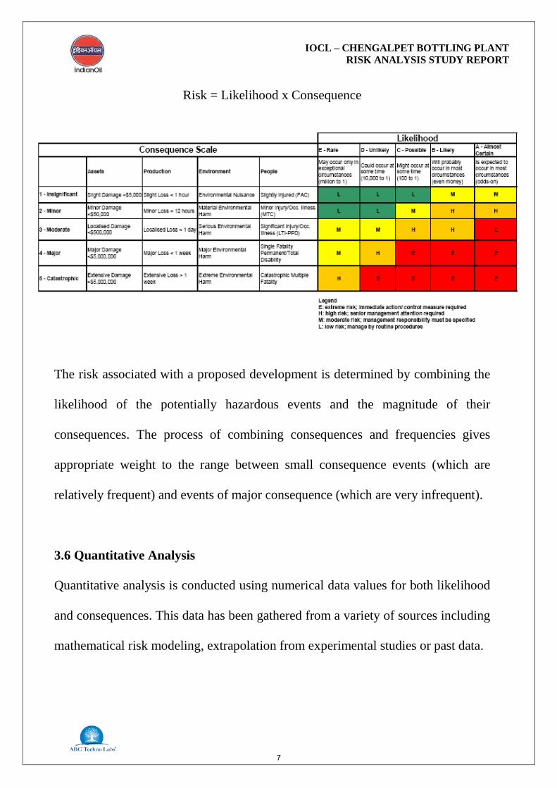
Risk = Likelihood x Consequence
The risk associated with a proposed development is determined by combining the
likelihood of the potentially hazardous events and the magnitude of their
consequences. The process of combining consequences and frequencies gives
appropriate weight to the range between small consequence events (which are
relatively frequent) and events of major consequence (which are very infrequent).
3.6 Quantitative Analysis
Quantitative analysis is conducted using numerical data values for both likelihood
and consequences. This data has been gathered from a variety of sources including
mathematical risk modeling, extrapolation from experimental studies or past data.
7

IOCL – CHENGALPET BOTTLING PLANT RISK ANALYSIS STUDY REPORT
A quantitative analysis can be used to estimate:
• Thermal radiation distances.
• Explosion overpressure.
• Toxic exposure levels and
• Fatality risk levels.
4. MANUFACTURING PROCESS FLOW CHART & DESCRIPTION
4.1 DESCRIPTION OF PROCESS
The bulk LPG storage & bottling facility at Chengalpet is operated by IOCL.
The plant functions primarily as LPG receipt, storage & bottling unit for filling
into various size cylinders.
The plant operations are categorized as,
1. Receipt of LPG
a. Transfer of LPG from M/s Indian Oil Petronas Pvt. Ltd. (M/s IPPL) through
bullet trucks
b. Truck unloading
c. LPG transfer to storage bullets
d. Storage of LPG in bullets
2. Receipt of Empty LPG Cylinders & Segregation
3. a. Bottling
i. Pumping of LPG to filling shed
8

IOCL – CHENGALPET BOTTLING PLANT RISK ANALYSIS STUDY REPORT
ii. Bottling of LPG cylinders – (Existing-1x24 Point electronic carousal + 1
Proposed)
iii. Quality check on filled cylinders
b. Loading into Trucks
4. Dispatch
a. Loading of filled cylinders in trucks
b. Supply & distribution to consumers through Authorized Vendors
I. Receipt of Product
LPG dosed with mercaptan will be received from M/s IPPL through bullet
trucks. There are 8 nos of Tank Lorry Decantation (TLD) Bays for the purpose
of unloading of bullet trucks and LPG will be stored in mounded vessels (3 x
600MT storage capacity).
II. Receipt of Empty LPG Cylinders & Segregation
Empty LPG cylinders will be received from vendor trucks & faulty cylinders
will be segregated at the point of receipt and diverted towards valve refitting
section.
III a. Bottling
LPG from storage bullets will be pumped to LPG filling shed 2 carousels (1
Existing + 1 Proposed) having 24 filling machines each. Cylinder bottling will
be the primary process to be carried out. After filling, each cylinder is subjected
to quality check for LPG leaks.
9

IOCL – CHENGALPET BOTTLING PLANT RISK ANALYSIS STUDY REPORT
IV. Dispatch
Filled cylinders will be loaded into respective Authorized Vendor trucks and
dispatched. Cylinders that are damaged are stored separately and subsequently
sold as scrap metal (after cutting) to authorized scrap dealers.
The process flow chart for LPG filling is shown in Figure 1.
Figure 1: Process Flow Chart
5. LIQUEFIED PETROLEUM GAS (LPG)
Liquefied Petroleum Gas (LPG) is a colourless and odourless gas. It is highly
flammable at normal temperature and pressure (flammability limits 2.2% to 9.6
% in air), therefore there should be no ignition sources in close proximity to
areas where LPG is stored and handled. On release it may give rise to both fire
10
IOCL – CHENGALPET BOTTLING PLANT RISK ANALYSIS STUDY REPORT
and explosion hazards. LPG is a blend of Propane and Butane, readily liquefied
under moderate pressure. LPG has a density of 1.5 to 2.0 and is heavier than air,
therefore, difficult to disperse. It should never be used or stored below ground,
as this could result in asphyxiation when released in a confined space. Since
LPG has only a faint scent, a mercaptan odorant is added to help in detection of
its leakage especially when used as a domestic fuel. In the event of a LPG leak,
the vaporization of liquid cools the surrounding atmospheric air and condenses
the water vapour contained in it to form a whitish fog, which is easy to observe.
LPG in fairly large concentrations displaces oxygen leading to a nauseous or
suffocating feeling.
Physical and chemical properties of LPG are as given below:
Boiling Point : - 42 ºC - 0ºC Vapour Pressure : 300 – 1400 kPa @ 40ºC Solubility in Water @ 20ºC : < 200ppm Physical State : Liquid Colour : Colourless Specific Gravity : Liquid 0.51 – 0.58 (water = 1) Vapour : 1.52 – 2.01 (air = 1) Auto ignition Temperature : 466.1 ºC Flammable Limits LEL
- Lower Flammability Limit (LFL) : 2.2% (in air v/v) Flammable Limits UEL
- Upper Flammability Limit (UFL) : 9.6% (in air v/v)
As part of LPG storage and filling facilities, IOCL has opted for mounded
bullets for storage of LPG. Hence in this case, there is no possibility of Boiling
11
IOCL – CHENGALPET BOTTLING PLANT RISK ANALYSIS STUDY REPORT
Liquid Expanding Vapour Explosion (BLEVE) as in the event of early fire,
flame impingement or heating of bullet will not be possible on mounded bullet.
Therefore, from mounded bullets, release of LPG is possible only from leakage
in piping, valves or flanges, etc.
6. HAZARDS FROM LPG STORAGE AND HANDLING
6.1 Jet Fire
If released LPG is ignited immediately, jet fire may take place. The extent of
injury to people depends on the heat flux and duration of exposure to heat.
6.2 Vapour Cloud Explosion
If released LPG is not ignited immediately, the cloud of vapour LPG will
spread in the surrounding area. LPG vapours are heavier than air and tend to
settle down at lower level. As long as the LPG concentration is between the
lower and higher flammability limits, the LPG vapour cloud may be set on fire
by an ignition source. For generation of over pressure effect, some degree of
confinement of the flammable cloud is required.
6.3 Flash Fire
When released quantities of LPG are not ignited immediately, vapour cloud of
LPG spreads in the surrounding area, some portion of LPG vapour cloud will
have LPG concentration between the lower and upper flammable limits, the
LPG vapour cloud may be set on fire by an ignition source in entire length of
12

IOCL – CHENGALPET BOTTLING PLANT RISK ANALYSIS STUDY REPORT
flammable LPG vapour cloud resulting flash fire. In the event of flash fire,
essentially, no over pressure effect is possible.
7. HAZARDOUS CONDITIONS DUE TO RELEASE OF LPG
As a result of release of LPG followed by immediate or delayed ignition,
following hazardous conditions may be encountered:
7.1 Thermal Effects
In case of jet fire, thermal effect is likely to cause injury or damage to people
and damage to objects. A substantial body of experimental data exists and forms
the basis for thermal effect estimation. The consequence caused by exposure to
heat radiation is a function of:
• Radiation energy onto the human body [kW/m2];
• Exposure duration [sec];
• Protection of the skin tissue (clothed or naked body).
The following damage distances for thermal radiation are used in the risk
analysis:
37.5 kW/m2 : Damage to process equipment. 100% fatality in 60 s
exposure. 1% fatality in 10 s exposure.
12.5 kW/m2 : First degree burn in 10 s exposure
4.0 kW/m2 : First degree burn in 30 s exposure
13
IOCL – CHENGALPET BOTTLING PLANT RISK ANALYSIS STUDY REPORT
7.2 Delayed Ignition and Explosion
In case of delayed ignition of LPG cloud, two physical effects may occur in
following ways:
• Flash fire over the whole or part of the LPG vapour cloud;
• Vapour cloud explosion that results in blast wave with typical peak
overpressures in circle around the ignition source. Vapour cloud explosion to
occur some degree of confinement is essential.
TNO Multi-energy method is used to calculate the blast overpressure. Table 1
gives extent of damage with respect to the peak overpressure resulting from a
blast wave:
Table 2 given provides an illustrative listing of damage effects caused by peak
overpressure.
8. IDENTIFICATION OF HAZARD FOR LPG UNLOADING AND
STORAGE AND FILLING
8.1 Categories of Hazards
For identification of hazards during handling and storage of LPG, it is essential
to identify categories of hazard. Hazard categories, which may be responsible
for accidental release of LPG from proposed expansion are listed in Table 3.
14

IOCL – CHENGALPET BOTTLING PLANT RISK ANALYSIS STUDY REPORT
8.2 Hazard Identification (HAZID)
Hazard Identification (HAZID) for the LPG storage and billing distribution
facilities has been carried out for likely hazardous events which may cause
major accident hazards. A systematic investigation has been carried with special
focus on external events that could potentially impact the operation and safety
of facility during transfer, storage and distribution of LPG.
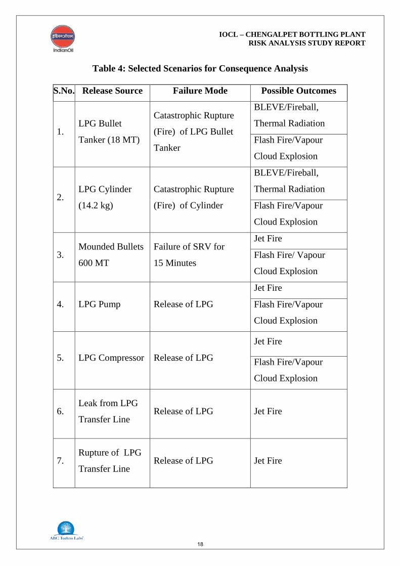
9. RELEASE AND OUTCOME SCENARIOS
Based on unloading conditions and storage & handling conditions of LPG at the
IOCL’s bottling plant, maximum credible LPG release and outcome scenarios
which may result during operation of LPG storage and filling facilities are given
in Table 4.
Table 1: Damage Effects Due to Overpressure
Peak Overpressure Extent of Type
0.830 bar Total Destruction
0.350 bar Heavy Damage
0.170 bar Moderate Damage
0.100 bar Minor Damage
15

IOCL – CHENGALPET BOTTLING PLANT RISK ANALYSIS STUDY REPORT
Table 2: Illustrative Damage Effects due to Overpressures
Peak Overpressure (Bar) Failure
0.005 5 % Window Shattering 0.02 50 % Window Shattering 0.07 Collapse of a roof of a tank 0.07-0.14 Connection failure of panelling 0.08-0.1 Minor Damage to Steel Framework 0.15-0.2 Concrete block wall shattered 0.2 Collapse of Steel Framework 0.2-0.3 Collapse of self framing Steel panel building 0.2-0.3 Ripping of empty oil tanks 0.2-0.3 Deformation of a pipe bridge 0.2-0.4 Big trees topple over 0.3 Panelling torn off 0.35-0.4 Piping failure 0.35-0.8 Damage to Distillation Column 0.4-0.85 Collapse of pipe bridge 0.5 Loaded Train Wagon overturned 0.5 Brick walls shattered
0.5-1.0 Movement of round tank, failure of connecting piping
(Source: TNO)
16
IOCL – CHENGALPET BOTTLING PLANT RISK ANALYSIS STUDY REPORT
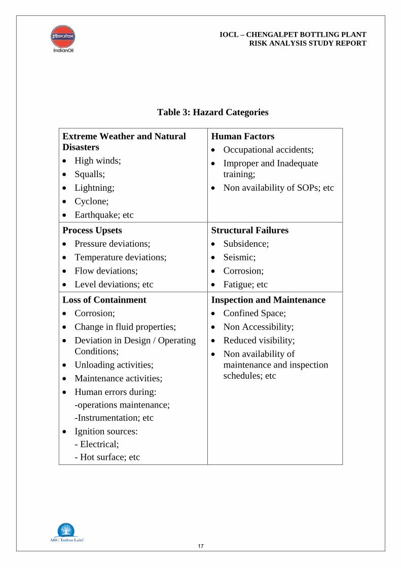
Table 3: Hazard Categories
Extreme Weather and Natural Disasters • High winds; • Squalls; • Lightning; • Cyclone; • Earthquake; etc
Human Factors • Occupational accidents; • Improper and Inadequate
training; • Non availability of SOPs; etc
Process Upsets • Pressure deviations; • Temperature deviations; • Flow deviations; • Level deviations; etc
Structural Failures • Subsidence; • Seismic; • Corrosion; • Fatigue; etc
Loss of Containment • Corrosion; • Change in fluid properties; • Deviation in Design / Operating
Conditions; • Unloading activities; • Maintenance activities; • Human errors during:
-operations maintenance; -Instrumentation; etc
• Ignition sources: - Electrical; - Hot surface; etc
Inspection and Maintenance • Confined Space; • Non Accessibility; • Reduced visibility; • Non availability of
maintenance and inspection schedules; etc
17
IOCL – CHENGALPET BOTTLING PLANT RISK ANALYSIS STUDY REPORT
Table 4: Selected Scenarios for Consequence Analysis
S.No. Release Source Failure Mode Possible Outcomes
1. LPG Bullet
Tanker (18 MT)
Catastrophic Rupture
(Fire) of LPG Bullet
Tanker
BLEVE/Fireball,
Thermal Radiation
Flash Fire/Vapour
Cloud Explosion
2. LPG Cylinder
(14.2 kg)
Catastrophic Rupture
(Fire) of Cylinder
BLEVE/Fireball,
Thermal Radiation
Flash Fire/Vapour
Cloud Explosion
3. Mounded Bullets
600 MT
Failure of SRV for
15 Minutes
Jet Fire
Flash Fire/ Vapour
Cloud Explosion
4. LPG Pump Release of LPG
Jet Fire
Flash Fire/Vapour
Cloud Explosion
5. LPG Compressor Release of LPG
Jet Fire
Flash Fire/Vapour
Cloud Explosion
6. Leak from LPG
Transfer Line Release of LPG Jet Fire
7. Rupture of LPG
Transfer Line Release of LPG Jet Fire
18
IOCL – CHENGALPET BOTTLING PLANT RISK ANALYSIS STUDY REPORT
10. CONSEQUENCE ANALYSIS
Subsequent to the accidental release of a LPG, the consequence depends on
various factors e.g. type and quantity, presence and location of an ignition
source, meteorological conditions, etc. The consequence analysis for the
selected accident scenarios for LPG release has been carried out to estimate the
effect distance or vulnerability zone. Once the effect distances are computed
for various failure cases, risk can be quantified and appropriate measures can
be taken for risk mitigation to eliminate damage to life and property and
enhance the safety.
10.1 Model Used For Consequence Analysis
The risk assessment study involves a large number of computations for which
established computing aids are essential.
PHAST (Version 6.53.1) software of DNV has been used to perform the
consequence calculations. PHAST is consequence analysis software for
calculation of physical effects (fire, explosion, atmospheric dispersion) of the
escape of hazardous materials. PHAST software allows detailed modeling and
quantitative assessment of release of pure chemicals and mixtures.
10.2 Consequence Analysis for LPG Release Scenarios
The consequence analysis has been carried out for various LPG release
scenarios as described in Table 4. Out comes of consequence analysis have
been described in subsequent section.
19

IOCL – CHENGALPET BOTTLING PLANT RISK ANALYSIS STUDY REPORT
10.3 Rupture of 18 MT Bullet Tanker
In the event of catastrophic rupture of 18 MT LPG bullet tanker, BLEVE may
be occurred on immediate ignition. Various outcomes in the event of
catastrophic rupture of LPG bullet tanker will be as given below under different
stability classes:
BLEVE: Fire Ball Occurrence
Outcome Parameters 18 MT LPG Bullet
Tanker
Duration of Fire Ball, (s) 78.25
Radius of Fire Ball, (m) 10.88
Fireball Lift Off Height (m) 156.51
Flame Emissive Power
(kW/m2)
285.56
Thermal Radiation: Fireball Ellipse
Radiation
Effects B, 3 m/s D, 3 m/s E, 2m/s
4 (kW/m2) 439.01 449.199 439.01
12.5 (kW/m2) 237.853 237.853 237.853
37.5 (kW/m2) 78.2269 78.2269 78.2269
20

IOCL – CHENGALPET BOTTLING PLANT RISK ANALYSIS STUDY REPORT
The intensity radii for fireball due to catastrophic rupture of 18 MT bullet truck
are given in Figure 2:
UEL & LEL Concentrations Distance (m)
Concentration B, 3 m/s D, 3 m/s E, 2m/s
UEL 48.4779 49.0013 49.0068
LEL 222.883 224.435 222.682
Figure 2: Intensity Radii for Fireball for 18MT Bullet Truck
21

IOCL – CHENGALPET BOTTLING PLANT RISK ANALYSIS STUDY REPORT
Maximum Distance (m) at Overpressure Level due to Early
Explosion
Concentration B, 3 m/s D, 3 m/s E, 2m/s
Overpressure
(0.1 bar) 191.144 191.144 191.144
Late explosion worst case radii for fire ball due to catastrophic rupture of 18
MT bullet truck are as given in Figure 3:
Figure 3: Late Explosion Worst Case Radii for 18 MT Bullet
22
IOCL – CHENGALPET BOTTLING PLANT RISK ANALYSIS STUDY REPORT
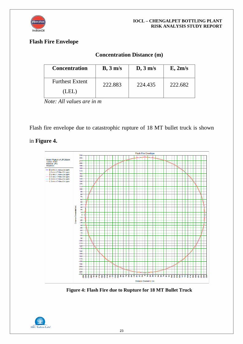
Flash Fire Envelope
Concentration Distance (m)
Concentration B, 3 m/s D, 3 m/s E, 2m/s
Furthest Extent
(LEL) 222.883 224.435 222.682
Note: All values are in m
Flash fire envelope due to catastrophic rupture of 18 MT bullet truck is shown
in Figure 4.
Figure 4: Flash Fire due to Rupture for 18 MT Bullet Truck
23
IOCL – CHENGALPET BOTTLING PLANT RISK ANALYSIS STUDY REPORT
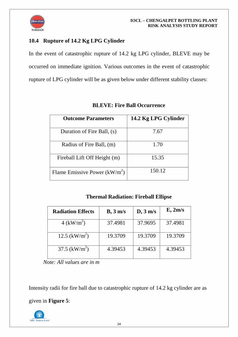
10.4 Rupture of 14.2 Kg LPG Cylinder
In the event of catastrophic rupture of 14.2 kg LPG cylinder, BLEVE may be
occurred on immediate ignition. Various outcomes in the event of catastrophic
rupture of LPG cylinder will be as given below under different stability classes:
BLEVE: Fire Ball Occurrence
Outcome Parameters 14.2 Kg LPG Cylinder
Duration of Fire Ball, (s) 7.67
Radius of Fire Ball, (m) 1.70
Fireball Lift Off Height (m) 15.35
Flame Emissive Power (kW/m2) 150.12
Thermal Radiation: Fireball Ellipse
Radiation Effects B, 3 m/s D, 3 m/s E, 2m/s
4 (kW/m2) 37.4981 37.9695 37.4981
12.5 (kW/m2) 19.3709 19.3709 19.3709
37.5 (kW/m2) 4.39453 4.39453 4.39453
Note: All values are in m
Intensity radii for fire ball due to catastrophic rupture of 14.2 kg cylinder are as
given in Figure 5:
24

IOCL – CHENGALPET BOTTLING PLANT RISK ANALYSIS STUDY REPORT
UEL & LEL Concentrations Distance (m)
Concentration B, 3 m/s D, 3 m/s E, 2m/s
UEL 4.59188 4.5956 4.59643
LEL 27.4572 27.4699 27.1581
Note: All values are in m
Figure 5: Intensity Radii for Fireball for 14.2 kg LPG Cylinder
25

IOCL – CHENGALPET BOTTLING PLANT RISK ANALYSIS STUDY REPORT
Maximum Distance (m) at Overpressure Level due to Early Explosion
Concentration B, 3 m/s D, 3 m/s E, 2m/s
Overpressure
(0.1 bar) 17.6617 17.6617 17.6617
Note: All values are in m
Late explosion worst case radii for fire ball due to catastrophic rupture of
14.2 kg LPG cylinder are as given in Figure 6:
Figure 6: Late Explosion Worst Case for 14.2 kg LPG Cylinder
26

IOCL – CHENGALPET BOTTLING PLANT RISK ANALYSIS STUDY REPORT
Flash Fire Envelope
Concentration Distance (m)
Concentration B, 3 m/s D, 3 m/s E, 2m/s
Furthest Extent (LEL) 27.4572 27.4699 27.1581
Note: All values are in m
Flash fire envelope due catastrophic rupture of 14.2 kg LPG cylinder is shown
in Figure 7.
Figure 7: Flash Fire due to Rupture for 14.2 Kg LPG Cylinder
27

IOCL – CHENGALPET BOTTLING PLANT RISK ANALYSIS STUDY REPORT
10.5 Release of SRV of Mounded Bullets of 600 MT
I. Jet Fire on Immediate Ignition
On release of LPG from SRV of mounded bullets, jet fire will be occurred on
immediate ignition. Thermal radiation distances from jet fire are given below:
Radiation Level Thermal Radiation Level Distances (m)
B, 3 m/s D, 3 m/s E, 2m/s
37.5 kW/m2 Not Reached Not Reached Not Reached
12.5 kW/m2 Not Reached Not Reached Not Reached
4 kW/m2 42.72 42.72 42.72
Thermal radiation intensity distance from jet fire is presented in Figure 8.
Figure 8: Thermal Intensity from Jet Fire due to Release from
28

IOCL – CHENGALPET BOTTLING PLANT RISK ANALYSIS STUDY REPORT
II. UEL and LEL Concentration Distances
In the event of release of LPG from SRV of mounded bullets, vapour cloud will
be formed if it is not getting source of ignition. LPG vapours under UEL and
LEL concentration will be occurred at following distances.
Concentration UEL and LEL Concentration Distances (m)
B, 3 m/s D, 3 m/s E, 2m/s
UEL 0.145 0.148 0.147
LEL 2.316 2.796 2.606
UEL and LEL Concentration Height
Concentration
UEL and LEL Concentration
Height (m)
B, 3 m/s D, 3 m/s E, 2m/s
UEL 11.38 11.51 11.53
LEL 25.104 26.573 25.33
III. Flash Fire Envelope
On ignition of LPG vapours within UEL and LEL, flash fire envelope will be
formed as details given below:
29
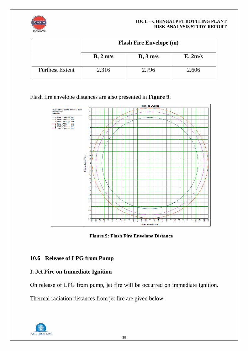
IOCL – CHENGALPET BOTTLING PLANT RISK ANALYSIS STUDY REPORT
Flash Fire Envelope (m)
B, 2 m/s D, 3 m/s E, 2m/s
Furthest Extent 2.316 2.796 2.606
Flash fire envelope distances are also presented in Figure 9.
10.6 Release of LPG from Pump
I. Jet Fire on Immediate Ignition
On release of LPG from pump, jet fire will be occurred on immediate ignition.
Thermal radiation distances from jet fire are given below:
Figure 9: Flash Fire Envelope Distance
30

IOCL – CHENGALPET BOTTLING PLANT RISK ANALYSIS STUDY REPORT
Radiation Level Thermal Radiation Level Distances (m)
B, 2 m/s D, 3 m/s E, 2m/s
37.5 kW/m2 Not Reached Not Reached Not Reached
12.5 kW/m2 10.09 10.09 10.09
4 kW/m2 18.97 18.97 18.97
Thermal radiation intensity radii from jet fire are also presented in Figure 10.
Figure 10: Radiation vs Distance from Jet Fire due to Release from
31

IOCL – CHENGALPET BOTTLING PLANT RISK ANALYSIS STUDY REPORT
II. UEL and LEL Concentration Distances
In the event of release of LPG from pump, vapour cloud will be formed if it is
not getting source of ignition. LPG vapours under UEL and LEL concentration
will be occurred at following distances.
Concentration UEL and LEL Concentration Distances (m)
B, 3 m/s D, 3 m/s E, 2m/s
UEL 0.084 0.083 0.079
LEL 1.038 1.073 1.041
UEL and LEL Concentration Height
Concentration UEL and LEL Concentration Height (m)
B, 3 m/s D, 3 m/s E, 2m/s
UEL 5.079 5.15 5.21
LEL 9.020 9.34 9.46
III. Flash Fire Envelope
On ignition of LPG vapours within UEL and LEL, flash fire envelope will be
formed as details given below:
32
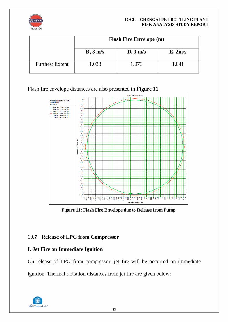
IOCL – CHENGALPET BOTTLING PLANT RISK ANALYSIS STUDY REPORT
Flash Fire Envelope (m)
B, 3 m/s D, 3 m/s E, 2m/s
Furthest Extent 1.038 1.073 1.041
Flash fire envelope distances are also presented in Figure 11.
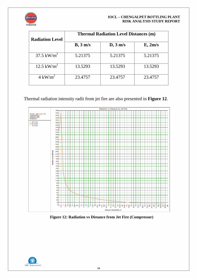
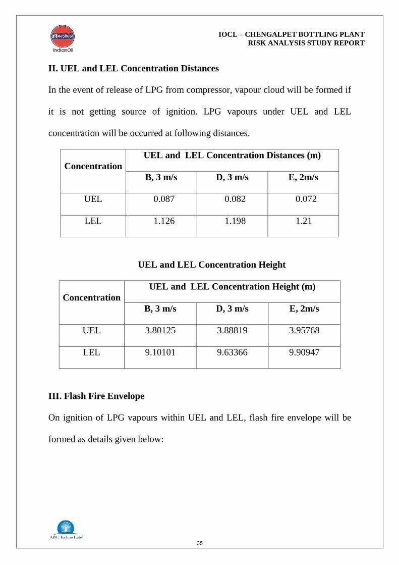
10.7 Release of LPG from Compressor
I. Jet Fire on Immediate Ignition
On release of LPG from compressor, jet fire will be occurred on immediate
ignition. Thermal radiation distances from jet fire are given below:
Figure 11: Flash Fire Envelope due to Release from Pump
33
IOCL – CHENGALPET BOTTLING PLANT RISK ANALYSIS STUDY REPORT
Radiation Level Thermal Radiation Level Distances (m)
B, 3 m/s D, 3 m/s E, 2m/s
37.5 kW/m2 5.21375 5.21375 5.21375
12.5 kW/m2 13.5293 13.5293 13.5293
4 kW/m2 23.4757 23.4757 23.4757
Thermal radiation intensity radii from jet fire are also presented in Figure 12.
Figure 12: Radiation vs Distance from Jet Fire (Compressor)
34
IOCL – CHENGALPET BOTTLING PLANT RISK ANALYSIS STUDY REPORT
II. UEL and LEL Concentration Distances
In the event of release of LPG from compressor, vapour cloud will be formed if
it is not getting source of ignition. LPG vapours under UEL and LEL
concentration will be occurred at following distances.
Concentration UEL and LEL Concentration Distances (m)
B, 3 m/s D, 3 m/s E, 2m/s
UEL 0.087 0.082 0.072
LEL 1.126 1.198 1.21
UEL and LEL Concentration Height
Concentration UEL and LEL Concentration Height (m)
B, 3 m/s D, 3 m/s E, 2m/s
UEL 3.80125 3.88819 3.95768
LEL 9.10101 9.63366 9.90947
III. Flash Fire Envelope
On ignition of LPG vapours within UEL and LEL, flash fire envelope will be
formed as details given below:
35

IOCL – CHENGALPET BOTTLING PLANT RISK ANALYSIS STUDY REPORT
Flash Fire Envelope (m)
B, 3 m/s D, 3 m/s E, 2m/s
Furthest Extent 1.126 1.198 1.21
Flash fire envelope distances are also presented in Figure 13.
10.8 Leak from LPG Transfer Line The leak scenarios are considered for the LPG lines with hole diameter of 8 mm
and 20 mm (20 % of pipe diameter). Lower flammability limit (LFL) of LPG
(0.00899 fraction with air) and upper flammability limit (UFL) (0.01799
fraction with air) determines the area covered for the case of flash fire.
Figure 13: Flash Fire Envelope due to Release from Compressor
36
IOCL – CHENGALPET BOTTLING PLANT RISK ANALYSIS STUDY REPORT
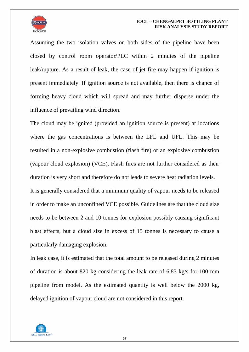
Assuming the two isolation valves on both sides of the pipeline have been
closed by control room operator/PLC within 2 minutes of the pipeline
leak/rupture. As a result of leak, the case of jet fire may happen if ignition is
present immediately. If ignition source is not available, then there is chance of
forming heavy cloud which will spread and may further disperse under the
influence of prevailing wind direction.
The cloud may be ignited (provided an ignition source is present) at locations
where the gas concentrations is between the LFL and UFL. This may be
resulted in a non-explosive combustion (flash fire) or an explosive combustion
(vapour cloud explosion) (VCE). Flash fires are not further considered as their
duration is very short and therefore do not leads to severe heat radiation levels.
It is generally considered that a minimum quality of vapour needs to be released
in order to make an unconfined VCE possible. Guidelines are that the cloud size
needs to be between 2 and 10 tonnes for explosion possibly causing significant
blast effects, but a cloud size in excess of 15 tonnes is necessary to cause a
particularly damaging explosion.
In leak case, it is estimated that the total amount to be released during 2 minutes
of duration is about 820 kg considering the leak rate of 6.83 kg/s for 100 mm
pipeline from model. As the estimated quantity is well below the 2000 kg,
delayed ignition of vapour cloud are not considered in this report.
37

IOCL – CHENGALPET BOTTLING PLANT RISK ANALYSIS STUDY REPORT
10.9 Rupture of LPG Transfer Line
The rupture scenario is considered for the LPG line located above the ground
with LPG bullets. It is expected that the rupture of the transfer line will result in
LPG gas release and dissipate into the atmosphere. As a result of immediate
ignition, jet fire may happen if ignition is available immediately. The heat
intensity, or thermal radiation flux, is expected to be highest at the centre of the
jet fire. The heat radiation decreases with distance from the centre, depending
on wind speed and atmospheric stability.
11. FAILURE FREQUENCY DATA BASE
An incident frequency can be derived from internationally well known generic
databases incase the design is sufficiently similar to facilities represented in the
historical failure records. This database can be used to meet the project scope
requirements including LPG storage facility failure data. Using these data, the
frequencies of incidents can be estimated. The frequency of each incident is
equal of the failure frequencies of all individual components.
11.1 Flanges
For flanges, industrial sources give figures covering the range of 6E-4 (in LPG
service) to 1.6E-4 (in liquid ammonia service) failures per year. Whittle (1993)
quotes a lower failure rate of 6.2E-5 failures per year, while the failure rate
38

IOCL – CHENGALPET BOTTLING PLANT RISK ANALYSIS STUDY REPORT
quoted by Sooby (1992) is even lower by over an order of magnitude of 3.3E-6
failures per year. Since the quality of the pipe flanges varies enormously with
application, it seems sensible to regard this range as a reflection of flange and
gasket quality. A failure frequency of 1E-5 per year is used for high quality
flanges (e.g. raised face, ring type, or grey lock flanges used in high pressure,
high temperature service). An analysis of flange failure hole sizes shows them
to be small. The analysis shows that the maximum equivalent hole diameter for
a flange leak from a 6 inch (15 mm) pipe is 12 mm. It has been assumed that for
pipes greater than 6 inch (15 mm) in diameter that 10% of all flange leaks
contribute to leaks in the range of 10 to 50 mm (i.e. 25 mm holes). For pipes of
6 inch (15 mm) diameter or smaller all leaks are taken to fall into the 0 to 10
mm hole size range (i.e. 5 mm holes).
Table 5 summarizes the leak frequencies for flanges by hole size.
Table 5: Frequencies of Flange Failure
S.No Hole size(mm) Failure Rate /year
1. 5 9.0 E-5
2. 25 1.0 E-5
3. Total 1.0 E-4
Leak frequencies for valve and flanges are summarized in Table 6 by hole size.
39

IOCL – CHENGALPET BOTTLING PLANT RISK ANALYSIS STUDY REPORT
Table 6: Frequencies of Valves and Flange Failure
S.No Hole
size(mm) Failure Rate /year
1. 5 4.22 E-5
2. 25 1.38 E-4
3. Rupture 5.11 E-5
11.2 Pumps Failure Frequencies
The NPRDS Annual Reliability Report gives the most detailed leak data records
for pumps. Most of the pumps failures is detected whilst the system is in
service, The failure modes "leak" and "crack" contribute to the 5 mm leak
category. The failure modes "breach", "collapse" and "fracture/break" contribute
to the 25 mm leak category. All failures are considered as common-mode
failures. The pump leak frequencies are summarized in Table 8.
Table 8: Frequencies for Leakage of Pump
Equivalent Hole
Size (mm)
Leak Frequency/Item year
Centrifugal
Single Seal Double Seal
5 5.2 E-2 7.5 E-3
25 1.0 E-3 1.0 E-3
100 or Rupture 1.0 E-4 1.0 E-4
Total 5.31E-2 8.6 E-3
Note: Maximum equivalent hole size for pumps is considered to be 100 mm
40
IOCL – CHENGALPET BOTTLING PLANT RISK ANALYSIS STUDY REPORT
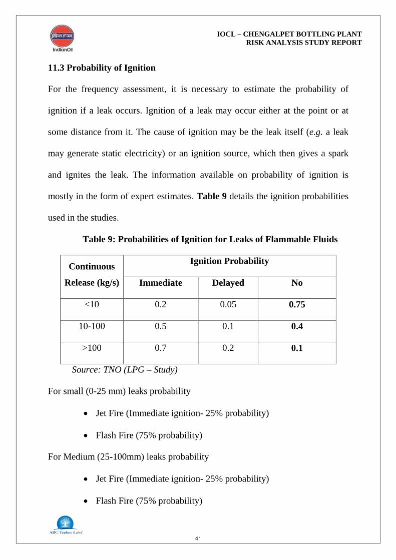
11.3 Probability of Ignition
For the frequency assessment, it is necessary to estimate the probability of
ignition if a leak occurs. Ignition of a leak may occur either at the point or at
some distance from it. The cause of ignition may be the leak itself (e.g. a leak
may generate static electricity) or an ignition source, which then gives a spark
and ignites the leak. The information available on probability of ignition is
mostly in the form of expert estimates. Table 9 details the ignition probabilities
used in the studies.
Table 9: Probabilities of Ignition for Leaks of Flammable Fluids
Continuous
Release (kg/s)
Ignition Probability
Immediate Delayed No
<10 0.2 0.05 0.75
10-100 0.5 0.1 0.4
>100 0.7 0.2 0.1
Source: TNO (LPG – Study)
For small (0-25 mm) leaks probability
• Jet Fire (Immediate ignition- 25% probability)
• Flash Fire (75% probability)
For Medium (25-100mm) leaks probability
• Jet Fire (Immediate ignition- 25% probability)
• Flash Fire (75% probability)
41

IOCL – CHENGALPET BOTTLING PLANT RISK ANALYSIS STUDY REPORT
The probability of ignition depends on the availability of a flammable mixture,
the flammable mixture and ignition source and the type of ignition source
(energy etc).
12. RISK REDUCTION MEASURES
Risk Assessment study provides a quantitative technique for assessing the
significance of the impact of any facility on its external environment, highlights
key areas for greater attention and provides a tool for comparing alternative
options. Though, it can not substitute for close attention to the fundamentals of
safety throughout the design process or for design reviews.
For risk reduction, attempts should be made to either reduce inventories that
could get released in the event of loss of containment or failure likelihood or
both as far as feasible. Risk Assessment identifies the dominant risk
contributors, which enables prioritisation of plants/section that deserve special
attention in terms of inspection and maintenance in particular and over all safety
management as a whole.
12.1 Risk Mitigation Measures
The LPG bottling plant is major accident hazard installations under
Manufacture, Storage, Import of Hazardous Chemicals. Rule, 1989 and
subsequent amendments. During design, construction and operation of the
42
IOCL – CHENGALPET BOTTLING PLANT RISK ANALYSIS STUDY REPORT
facilities, numbers of safety provisions and risk reduction measures will need to
be implemented and followed meticulously in compliance with applicable acts,
rules, regulations, codes, standards, guidelines and best industry practices. This
also includes provisions of not only state-of-the-art equipment, control and
instrumentation to enhance safety but also high level induction and refresher
safety trainings from senior management to contractual workers levels at the
facilities.
Risk mitigation measures for the LPG bottling plant are described below:
12.2 Mounded Bullets
The mounded storage of LPG has proved to be safer as compared to above
ground storage vessels since it provides intrinsically passive and safe
environment and eliminates the possibility of Boiling Liquid Expanding Vapour
Explosion (BLEVE). The cover of the mound protects the vessel from fire
engulfment, radiation from a fire in close proximity and acts of sabotage or
vandalism. The area of land required to locate a mounded system is minimal
compared to conventional storage.
43
IOCL – CHENGALPET BOTTLING PLANT RISK ANALYSIS STUDY REPORT
The following measures are suggested during design, erection and operation of
mounded storage bullets for LPG.
i. Provisions of “OISD Standards 150: Design and Safety
Requirements for Liquefied Petroleum Gas Mounded Storage
Facility” shall be included in design and operation.
ii. Each mound bullet shall have accessibility to fire tender from at
least two sides.
iii. Minimum separation distance between mounded LPG storage and
any other (other than LPG pump/compressor house) facility
associated with LPG plant shall be 15 meters. This distance to be
measured from the edge of the mound at finished ground level and
also from the first valve on the vessel i.e. ROV.
iv. The minimum inter-distance between the edges of the vessel in a
mound shall not be less than 2 meters.
v. Proper provision shall be made for countering the consequences of
the settlement of the vessel under mound. The surrounding of the
bottom connection should be filled with such material that can
absorb such settlement.
vi. Provision shall be made to monitor the settlements of the mound by
providing permanent reference point. A minimum of three
reference points shall be installed to be able to also identify
44
IOCL – CHENGALPET BOTTLING PLANT RISK ANALYSIS STUDY REPORT
possible vessel bending (One each near the vessel ends and one in
the middle.)
vii. The fire safe Remote Operated Shutdown Valve (ROV) on liquid
drain line from the vessel shall be either from bottom of the vessel
or from the top of the vessel as per the design considerations.
viii. In case of liquid drain line from the bottom of the vessel, the
minimum distance of 3 meters from the vessel to ROV shall be
maintained. The nozzle pipe shall have a slope of 1.5 Deg.
ix. There shall not be any other flanges, or any other tapping up-to the
ROV except in case of liquid drain line from top of the vessels.
x. Each vessel shall have at-least two pressure relief valves. The full
flow capacity of Pressure Relief Valves (PRV) on mounded vessels
may be reduced to not less than 30% of the capacity required for an
equivalent size of above ground vessel. For safety reasons, the
discharge of Pressure Relief Valves shall be connected to flare
system. In this case Pressure Relief Valves (PRVs) shall have lock
open (or car seal open) type isolation valves on both sides of
Pressure Relief Valve.
xi. The Pressure Relief valves shall be tested and calibrated every year
by a competent person and records shall be maintained.
45
IOCL – CHENGALPET BOTTLING PLANT RISK ANALYSIS STUDY REPORT
xii. Cathodic protection system shall be provided, maintained and
tested routinely.
xiii. Any change in the system will be marked on P&ID. The system of
“Management of Changes” may be developed as per “Guidelines
on Management of Change” (OISD GDN 178).
xiv. Any repairs or modifications should be undertaken after statutory
approval from applicable authority.
xv. Each storage vessel shall have minimum two different types of
level indicators and one independent high level switch. High level
alarms shall be set at not more than 85% level of the volumetric
capacity of the vessel.
xvi. Audiovisual indication shall be at local panel and control room.
xvii. Automatic fire detection and /or protection (Fixed) system based
on heat detection through thermal fuses/ quartz bulbs shall be
employed. Sensors shall be installed at all critical places including
as described below:
• Minimum 1 detector shall be provided on each exposed portion
of the vessel. However if the nozzles are covered in a dome,
each group shall have 2 numbers of detectors.
• At least one near the each liquid line ROV to take care of failure
of flanges.
46
IOCL – CHENGALPET BOTTLING PLANT RISK ANALYSIS STUDY REPORT
xviii. Suitable gas detectors shall be placed at critical locations in
the LPG storage area such as, near the ROV, in inspection tunnel,
near water draining/ sampling points, etc.
xix. Audio- visual alarms showing the location of gas leakage shall be
provided on the control panel in the control room. First level alarm
can be set at 20% LEL and second level alarm at 40 % LEL of
LPG.
xx. All mounded storage vessels, LPG Pump Houses, Bullet Tanker
Gantries shall be fully covered by medium velocity water spray
system.
xxi. LPG storage area, automatic detection of heat for automatic
actuation of medium velocity sprinkler system having remote/ local
operated deluge valve with spray density of 10 lpm/m2 of surface
area shall be provided.
xxii. Hydrant and monitor coverage shall also be provided on all four
sides of the mounds for adequate coverage of unprotected portions
exposed to thermal radiation including for top of the mound and for
piping, in the immediate vicinity of the mound. In view of
accessibility of unprotected portions of the vessels, for
effectiveness, installation of remote operated monitors at
appropriate height shall be considered.
47
IOCL – CHENGALPET BOTTLING PLANT RISK ANALYSIS STUDY REPORT
xxiii. Hydrant /monitors shall be located at a safe place around the
mound. In any case fire hydrant and/or monitors shall not be
installed within 15 meters from the facilities/equipment to be
protected.
12.3 Maintenance Schedules
The proper preventive maintenance schedule should be prepared to facilitate the
maintenance service to be rendered in a planned manner covering the necessary
work to be done, mentioning the periodicity i.e. daily, weekly, monthly, half
yearly and yearly schedules.
12.4 Electrical Hazards
Some Important measures to minimise electrical hazards are as given below:
• The classification of area for electrical installations at LPG storage
and handling facilities shall be as per OISD Standards 113.
• Inspection of electrical equipment shall be carried out as per OISD
Standards 137.
• All electrical equipments shall be provided with proper earthing.
• Earth pits shall be periodically tested and maintained in good
condition.
48
IOCL – CHENGALPET BOTTLING PLANT RISK ANALYSIS STUDY REPORT
• Emergency lighting shall be available at all critical locations including
fire pump room, control room, etc.
• All electrical equipments shall be free from carbon dust, oil deposits,
and grease.
• All electrical cable will be tagged for easy identification and cable
routing shall be planned away from heat sources, gas, water, oil, drain
piping and air conditioning ducts.
• All lights in LPG storage area, pump house, unloading bays, etc will
be flame proof.
• Provisions shall be made for approved insulated tools, rubber mats,
shock proof gloves and boots, tester, fuse tongs, discharge rod, hand
lamp, insulated ladder.
• Flame and shock detectors and central fire announcement system for
fire safety shall be provided in MCC control panel room.
• Temperature sensitive alarm and protective relays to make alert and
disconnect equipment before overheating shall be provided.
• Danger from excess current due to overload or short circuit should be
prevented by providing fuses, circuit breakers, thermal protection, etc.
• Only carbon dioxide and dry chemical fire extinguishers shall be used
for electrical fires.
49
IOCL – CHENGALPET BOTTLING PLANT RISK ANALYSIS STUDY REPORT
12.5 Fire Fighting Facilities
Fire protection system shall be designed in accordance with the requirements of
OISD, NFPA standards, design requirements and safe engineering practices.
Fire fighting facilities should have full capability for early detection and
suppression of fire. The fire fighting system will primarily consist of:
• Hydrant system
• Foam protection system
• Deluge sprinkler system
• Portable fire extinguisher
• Fire detection and alarm system
Occupational Health, Safety & Environmental Features in the Project
Process Safety & Safety Features
Process Safety focuses on the prevention of fires, explosions and accidental
chemical releases at LPG Bottling facilities.
Safety Management Systems
The Safety Officer in co-ordination with Shift-in-Charge review all plant
operations to identify potential unsafe conditions and / or potential problems
which may lead to health or safety exposures.
50

IOCL – CHENGALPET BOTTLING PLANT RISK ANALYSIS STUDY REPORT
Plant personnel shall work with the Safety Officer to identify potential problems
and to identify proper operational procedures and the operational areas of the
plant. Actions to be taken include equipment or procedural changes,
development of exposure monitoring strategies, and inclusion of warning
statements in procedures.
Hazard Analysis by the Team
QRA studies are conducted at plant before commissioning and also applied to
the proposed installation and modification of buildings, equipments, mechanical
and electrical systems, utilities, fire protection system, grounds etc. Plans or
specifications on designated projects shall be submitted to an acceptance
committee consisting of Operations Manager, Engineering. Manager, Safety
Manager for review prior to project implementation. Recommendations will be
submitted with the final plans and specifications to the Departmental head for
review. If the departmental head finds that plans and specifications are not
meeting the recommendations of the acceptance committee, he shall return the
final plans to the originator for modifications or a justification of deviations.
Inspections
The officer in charge of each function is responsible for ensuring the timely
completion of periodic inspections and correction of problems.
51

IOCL – CHENGALPET BOTTLING PLANT RISK ANALYSIS STUDY REPORT
The frequency of specific inspections is as follows:
Safety Facilities in the Plant
• Leak detection, prevention
• Elimination of source of ignition
• Fire prevention / fighting
• Communication, First aid, Rescue and Personnel protection equipment.
Leak Detection:
Gas Monitoring System:
The system consists of gas detecting sensors with a control panel and audio /
visual alarms. Currently 34 gas sensors are installed in the plant, the location of
the sensors are give in the below table. Two additional gas sensors will be
installed for the proposed expansion, new carousel in and new carousel out.
The sensors give an initial alarm at 20% LEL and continuous alarm at 40%
LEL.
Location of Existing GMS Sensors
1 Bullet 1 ROV
2 Bullet 1 Access Tunnel
3 Bullet 1 Man Hole 1
4 Bullet 1 Man Hole 2
5 Bullet 2 ROV
6 Bullet 2 Access Tunnel
52

IOCL – CHENGALPET BOTTLING PLANT RISK ANALYSIS STUDY REPORT
7 Bullet 2 Man Hole 1
8 Bullet 2 Man Hole 2
9 Bullet 3 ROV
10 Bullet 3 Access Tunnel
11 Bullet 3 Man Hole 1
12 Bullet 3 Man Hole 2
13 47.5 Kg Filling Machine
14 LPG P/H Pump
15 LPG P/H Compressor
16 Carousal In
17 Carousal Out
18 Evacuation
19 ICU
20 Valve Change Shed
21 Filled Cylinder Shed
22 TLD BAY No.1
23 TLD BAY No.2
24 TLD BAY No.3
25 TLD BAY No.4
26 TLD BAY No.5
27 TLD BAY No.6
28 TLD BAY No.7
29 TLD BAY No.8
30 TLD BAY END
31 Filled Cylinder Shed
32 Bullet 1 Drain
53

IOCL – CHENGALPET BOTTLING PLANT RISK ANALYSIS STUDY REPORT
Proposed Leak Prevention / Minimizing:
Air / Vapour Extraction System: It is basically a blower with ducts extended
to different operating points in filling shed. The blower extract any leaking
LPG vapour from the floor level and cold flares the same to free atmosphere at
LPG cylinder filling shed.
Remote Control Valves:
These are electro – pneumatically operated quick shut off valves provided on
LPG pipelines with actuating points located remotely and nearer to operating
facilities in plant. When actuated, the valves will close within 25 seconds,
starving the LPG flow in pipelines. The ROV’s are installed at the following
locations:
• Storage bullets Liquid & Vapour lines
• TLD liquid lines
• LPG Pump out let lines near filling shed
33 Bullet 2 Drain
34 Bullet 3 Drain
54
IOCL – CHENGALPET BOTTLING PLANT RISK ANALYSIS STUDY REPORT
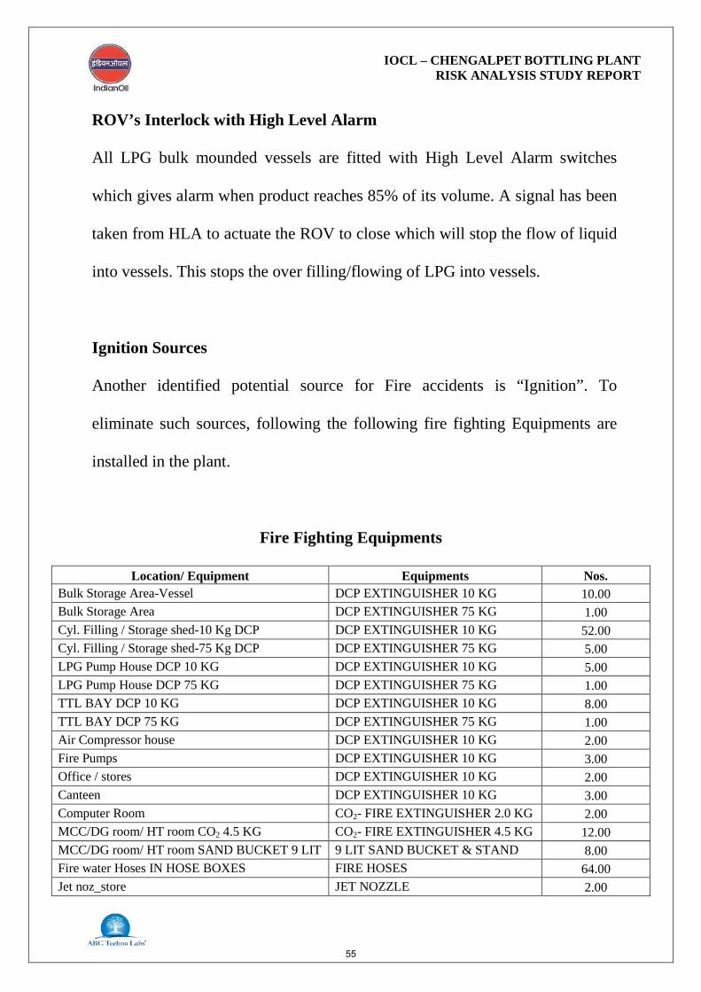
ROV’s Interlock with High Level Alarm
All LPG bulk mounded vessels are fitted with High Level Alarm switches
which gives alarm when product reaches 85% of its volume. A signal has been
taken from HLA to actuate the ROV to close which will stop the flow of liquid
into vessels. This stops the over filling/flowing of LPG into vessels.
Ignition Sources
Another identified potential source for Fire accidents is “Ignition”. To
eliminate such sources, following the following fire fighting Equipments are
installed in the plant.
Fire Fighting Equipments
Location/ Equipment Equipments Nos. Bulk Storage Area-Vessel DCP EXTINGUISHER 10 KG 10.00 Bulk Storage Area DCP EXTINGUISHER 75 KG 1.00 Cyl. Filling / Storage shed-10 Kg DCP DCP EXTINGUISHER 10 KG 52.00 Cyl. Filling / Storage shed-75 Kg DCP DCP EXTINGUISHER 75 KG 5.00 LPG Pump House DCP 10 KG DCP EXTINGUISHER 10 KG 5.00 LPG Pump House DCP 75 KG DCP EXTINGUISHER 75 KG 1.00 TTL BAY DCP 10 KG DCP EXTINGUISHER 10 KG 8.00 TTL BAY DCP 75 KG DCP EXTINGUISHER 75 KG 1.00 Air Compressor house DCP EXTINGUISHER 10 KG 2.00 Fire Pumps DCP EXTINGUISHER 10 KG 3.00 Office / stores DCP EXTINGUISHER 10 KG 2.00 Canteen DCP EXTINGUISHER 10 KG 3.00 Computer Room CO2- FIRE EXTINGUISHER 2.0 KG 2.00 MCC/DG room/ HT room CO2 4.5 KG CO2- FIRE EXTINGUISHER 4.5 KG 12.00 MCC/DG room/ HT room SAND BUCKET 9 LIT 9 LIT SAND BUCKET & STAND 8.00 Fire water Hoses IN HOSE BOXES FIRE HOSES 64.00 Jet noz_store JET NOZZLE 2.00
55
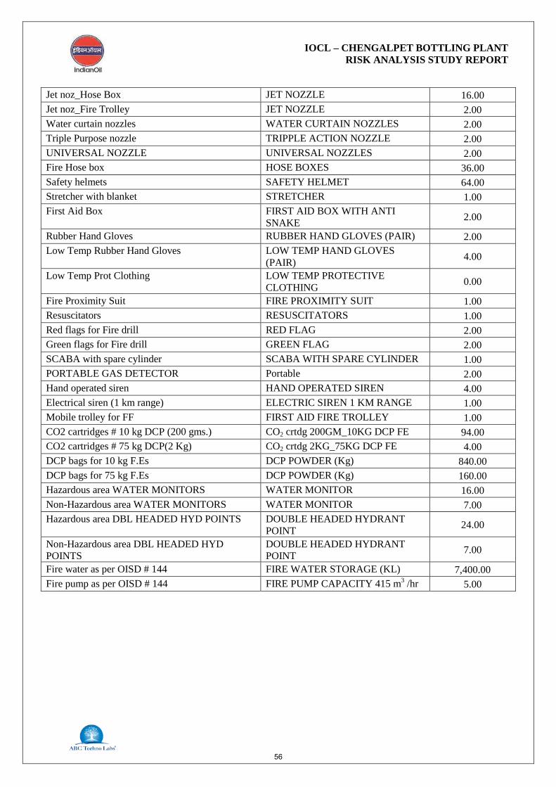
IOCL – CHENGALPET BOTTLING PLANT RISK ANALYSIS STUDY REPORT
Jet noz_Hose Box JET NOZZLE 16.00 Jet noz_Fire Trolley JET NOZZLE 2.00 Water curtain nozzles WATER CURTAIN NOZZLES 2.00 Triple Purpose nozzle TRIPPLE ACTION NOZZLE 2.00 UNIVERSAL NOZZLE UNIVERSAL NOZZLES 2.00 Fire Hose box HOSE BOXES 36.00 Safety helmets SAFETY HELMET 64.00 Stretcher with blanket STRETCHER 1.00 First Aid Box FIRST AID BOX WITH ANTI
SNAKE 2.00
Rubber Hand Gloves RUBBER HAND GLOVES (PAIR) 2.00 Low Temp Rubber Hand Gloves LOW TEMP HAND GLOVES
(PAIR) 4.00
Low Temp Prot Clothing LOW TEMP PROTECTIVE CLOTHING 0.00
Fire Proximity Suit FIRE PROXIMITY SUIT 1.00 Resuscitators RESUSCITATORS 1.00 Red flags for Fire drill RED FLAG 2.00 Green flags for Fire drill GREEN FLAG 2.00 SCABA with spare cylinder SCABA WITH SPARE CYLINDER 1.00 PORTABLE GAS DETECTOR Portable 2.00 Hand operated siren HAND OPERATED SIREN 4.00 Electrical siren (1 km range) ELECTRIC SIREN 1 KM RANGE 1.00 Mobile trolley for FF FIRST AID FIRE TROLLEY 1.00 CO2 cartridges # 10 kg DCP (200 gms.) CO2 crtdg 200GM_10KG DCP FE 94.00 CO2 cartridges # 75 kg DCP(2 Kg) CO2 crtdg 2KG_75KG DCP FE 4.00 DCP bags for 10 kg F.Es DCP POWDER (Kg) 840.00 DCP bags for 75 kg F.Es DCP POWDER (Kg) 160.00 Hazardous area WATER MONITORS WATER MONITOR 16.00 Non-Hazardous area WATER MONITORS WATER MONITOR 7.00 Hazardous area DBL HEADED HYD POINTS DOUBLE HEADED HYDRANT
POINT 24.00
Non-Hazardous area DBL HEADED HYD POINTS
DOUBLE HEADED HYDRANT POINT 7.00
Fire water as per OISD # 144 FIRE WATER STORAGE (KL) 7,400.00 Fire pump as per OISD # 144 FIRE PUMP CAPACITY 415 m3 /hr 5.00
56
IOCL – CHENGALPET BOTTLING PLANT RISK ANALYSIS STUDY REPORT
12.6 Control Room
• Control room shall be located at a sufficient distance from operating
areas
• All control room should be blast proof and shock proof.
• Critical switches and alarm should be always kept in line.
• Minimum number of doors shall be provided in the control room
while at least two doors should be provided for safe exit during
emergency.
• Smoke detection system shall be provided for control room.
12.7 Safety Audit and Inspection
Checklist based routine inspection and safety audits should be carried out in line
with OISD -144 for mounded bullets, pumps, piping and unloading bays, etc.
Any gap or non compliance should be implemented on priority in time bound
manner.
12.8 Induction and Refresher Safety Trainings
The provision shall be made for structured induction and refresher safety
trainings for LPG handling system from senior management to contractual
workers levels at the facilities.
57

IOCL – CHENGALPET BOTTLING PLANT RISK ANALYSIS STUDY REPORT
12.9 Emergency Response Plan
Anticipating and planning for various contingencies is crucial for ensuring the
success of any emergency response actions in an actual Emergency Situation.
On-site Emergency response plan shall be prepared for LPG Storage and filling
facilities, to take the action in an unlikely event of emergency due to accidental
release of LPG. Emergency Response Plan should be updated based on findings
of mock drills.
12.10 Mock Drill Exercises
Mock drill should be conducted once in six months. Exercises or drills have two
basic functions, namely training and testing. While exercises do provide an
effective means of training in response procedures, their primary purpose is to
test the adequacy of the emergency management system and to ensure that all
response elements are fully capable of managing an unlikely emergency
situation.
Mock drills are best means of accomplishing the following goals and objectives:
• To reveal weaknesses in the plans and procedures before emergencies occur. • To identify deficiencies in resources (both in manpower and equipment).
• To improve the level of co-ordination among various response personnel,
departments and agencies.
• To clarify each individual’s role and areas of responsibility.
58