Embed Size (px)
Citation preview
International Journal of Scientific & Engineering Research Volume 8, Issue 5, May-2017 358 ISSN 2229-5518
IJSER © 2017 http://www.ijser.org
Reliability Assessment of Axial Load Effect on Electric Power Distribution Concrete Poles in
Southwest Nigeria Quadri Ajibola Ibrahim*, Afolayan Joseph Olasehinde
Abstract— Electric power is distributed by overhead distribution line fixed on wooden or concrete poles. Often times these poles are susceptible to extreme damage from hazard under excessive loads occasioned by storm and accident impact by vehicles. In this research, numerical study was ac-complished to assess the vulnerability of typical tapered electric power distribution concrete poles of height 9 m under ambivalent loading conditions. The reaction of the poles to the environmental loading was determined with the help of SAP2000 Advanced 14.0.0 finite element analysis software pro-gram. The British Standard Code (BS 8110-1:1997) was adopted to generate the limit states equation with the load combination being at adverse effect. The reliability level of the concrete poles was extrapolated using the First-Order reliability Method (FORM) encoded in CalREL, a multipurpose structural reliability analysis software. Since every natural event is unpredictable, the interaction between the capacity of a pole and the demand (axial forces) on it must also be uncertain. The study shows that the reliability level of the poles increase as the reinforcement ratio increases but decrease as the cross-sections of the concrete poles decrease or as the heights increase, above 4.5m height, the probability of failure of the Nigerian concrete poles is high. Critical positions/areas of the concrete poles that require amendment have been identified based on the implied levels of reliability and when factors affecting material properties, geometry and loading are considered random in nature. Index Terms— Concrete poles, Reliability analysis, CalREL SAP 2000, Axial forces.
—————————— ——————————
1 INTRODUCTION
n recent times, efforts have been geared towards the pro-duction of Electric Power Distribution Concrete poles
(EPDC) that meet the international quality standards. With the level of development in Nigeria, the use of EPDC poles has been on the increase as a result of the rural electrification programme. In effect, efforts have been made to provide quality facilities and amenities for the production of poles in the rural and urban areas. Reinforced concrete is a viable and durable material for building and construction that can be formed into various forms and sizes. Its utility and versatility are achieved by combining the best features of concrete and other materials. In Nigeria, electricity is transmitted by con-ductors carried overhead by concrete and wooden poles. Concrete pole design is dependent on the power and voltage that is to be transmitted. In Nigeria, 33/11/0.415KV is usually transmitted generally by overhead conductors; hence the wooden and concrete pole types are suitable for use [8]. The design of poles are mainly based on the principle of loading. However, sag-tension calculation is quite involved due to the varying loading effect on conductors and the nature of con-ductor materials. The technology advancements in recent years have pro-pelled the use of concrete poles into an ever increasing, and significant role in the design and construction of high voltage electrical transmission lines. These technologies sig-nificantly have occurred in three key aspects namely; the types and quality of the raw materials utilized in the produc-tion of high performance concrete have dramatically im-proved, and in some instances have just recently been devel-oped. Also, scaled up manufacturing methods and equipment to produce high quality, stronger, longer length poles are being realized. [11]
Due to shear forces been small compared to bending mo-ments, concrete poles are very resilient. Axial loads are also significant, and should not be ignored most especially when the structure is guyed. Stresses induced by handling, trans-portation and erection should always be considered in the design of electric transmission. Besides, weight of cross arms and other attachments should be put into proper consideration in calculating the center of gravity of the electric transmission pole [15]. Generally, concrete is poor in tension, the tensile strength only accounted for about 10% of the compressive strength. Due to this, nearly all reinforced concretes are designed on the assumption that concrete does not resist any tensile force. Reinforcement is designed to carry these tensile forces, which are transferred by bonds between the interface of the two ma-terials. If this bond is not adequate, the reinforcing bars will slip within the concrete and there will not be a composite ac-tion. [5].
2 POWER DISTRIBUTION SYSTEMS The electric power system can be broadly divided into three subsystems: generation, transmission, and distribution. The generation plants produce electricity by using fossil fuels, nuclear energy, or renewable sources of energy. The power is then transported in bulk using the transmission system that uses wires supported by steel towers that are about 45 metres high and spaced about 240 metres apart [16]. The voltage le-vels for the transmission system ranges from 34.5 KV to as high as 1100 KV in the US [5]. The distribution system trans-ports and delivers power to the consumers after the voltage has been stepped down to the appropriate level. The distribu-tion system uses wires that are carried by timber, steel or con-crete poles that are 9 to 12 metres high and spaced 30 metres
I IJSER
International Journal of Scientific & Engineering Research Volume 8, Issue 5, May-2017 359 ISSN 2229-5518
IJSER © 2017 http://www.ijser.org
to 45metres. in the suburbs and 90metres to 120metres in ru-ral areas [14]. The voltage is usually between 4.16 KV to 34.5 KV in the primary distribution system [5]. Considering failure due to natural hazards, the distribution system is the most vulnerable [6]. This is because the generation stations are few and are usually designed to withstand high wind, floods, and earthquakes. The transmission system (towers and lines) is also designed to withstand natural hazards better than the distribution system. Another reason is that unlike the distri-bution system, there is always redundancy in the transmis-sion system, i.e. there is always more than one way to trans-port the electricity from the generation plants. . 2.2 Structural Reliability Reliability is the ability of the structure to meet the construc-tion requirements set out under specific conditions during the service life, according to which it is designed. It refers to the carrying capacity, serviceability and durability of construc-tion and according to them different degrees of reliability can be defined. One of the best ways of presenting the size of the uncertainty in the theory of reliability is the reliability index, because it is a measure of security that can be used in the comparison between the different elements or entire system [17]. The concept of structural reliability was incorporated into design methods in the seventies in the form of Load and Resistance Factor Design (LRFD). The objective of structural design based on reliability theory is to reduce the probability of failure to a tolerable level. [13] on Probabilistic assessment of electric power distribution concrete poles, examined the overturning moment on 2.2.1 Limit State The limit state is the state of the structure at which the object performance transforms from acceptable to unacceptable. There are several types of limit states: design limit state, ser-viceability limit states, serviceability limit state of fatigue. Any of these conditions can be defined by limit state function:
(1) where S is the resistance, i.e. the capacity of the construction and Q is a load, or the load on the construction [10]. If , it leads to unauthorized breakage of constructions and its performance, and if , structures performance are satis-fied. In the case of design limit states or bending capacity, S represents structure bending capacity, while Q represents the load bending moment. In the case of serviceability limit states, S may represent a maximum allowable deflection of the structure, while Q can represent deflection under load. However, the limit state function may be more complex (eg. nonlinear) and its parameters can be variable in time.
2.2.2 Application of Reliability Concept Probability of achieving the ultimate limit state can be ex-plained by the equation:
(2) Probability is equal to the cumulative distribution function of the random variable . The reliability index is defined as a function of the probability :
, (3) (4)
Where ф and ф-1 are the function of the standard normal cumulative distribution. The reliability index β is a measure of security that can be used in the comparison between the different elements or entire system [12].
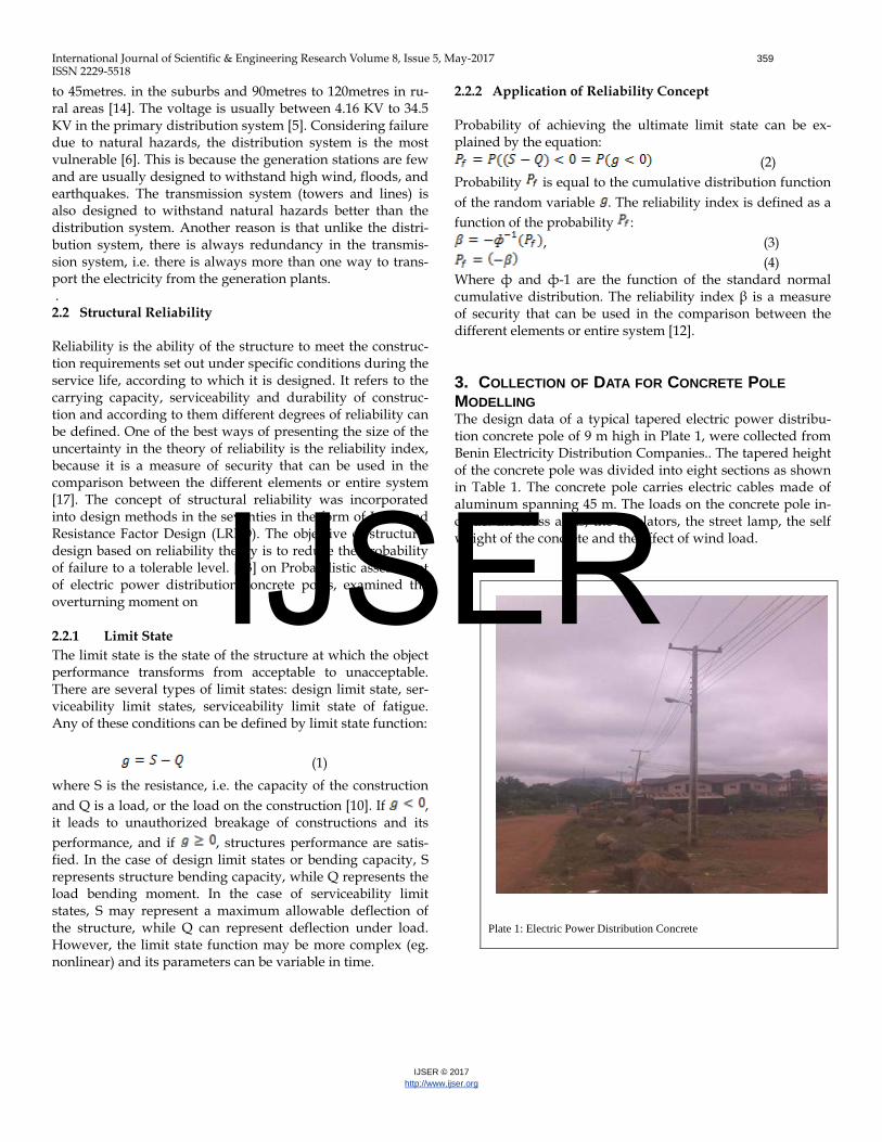
3. COLLECTION OF DATA FOR CONCRETE POLE MODELLING The design data of a typical tapered electric power distribu-tion concrete pole of 9 m high in Plate 1, were collected from Benin Electricity Distribution Companies.. The tapered height of the concrete pole was divided into eight sections as shown in Table 1. The concrete pole carries electric cables made of aluminum spanning 45 m. The loads on the concrete pole in-clude: the cross arms, the insulators, the street lamp, the self weight of the concrete and the effect of wind load.
Plate 1: Electric Power Distribution Concrete
IJSER
International Journal of Scientific & Engineering Research Volume 8, Issue 5, May-2017 360 ISSN 2229-5518
IJSER © 2017 http://www.ijser.org
Table 1: Section Properties of the Concrete Pole
Pole Sec-tions
Height (mm) Width (mm) Depth (mm)
1 0 350 300
2 0-1500 320 260
3 1500-3000 300 240
4 3000-4500 270 220
5 4500-6000 220 210
6 6000-7000 200 185
7 7000-8000 160 157
8 8000-9000 140 140
3.1 Load Data (i) Dead Load (a) Weight of Concrete
Total volume of concrete = 3.98m3
Unit Weight of Concrete = 24kN/m3
Weight of Concrete = 3.98x24 = 95.5 kN (b) Cross arms and Insulator = 0.15 kN/m2
(c) Street Lamp = 0.005 kN/m2 (d) The self-weight of aluminum = 0.86kN/m2
(ii) Wind Load
BS 6399-2:1997 (Code of Practiced for wind loading), was used for the analysis of wind load The dynamic pressure is given as
(5) where; and
(6) In which is the wind speed taken as 3.6m/s ac-cording to local wind condition in Akure, Ondo State (Adaramola and Oyewola, 2011).
is the risk coefficient taken as 1.0 is the terrain factor taken as 1.0 for flat terrain.
Therefore, =
3.2 SAP2000 Build-Up Analysis The SAP2000 (ref) Application Programming Interface (API) allows users to automatic operate many of the processes required to build, analyze and design models and to obtain customized
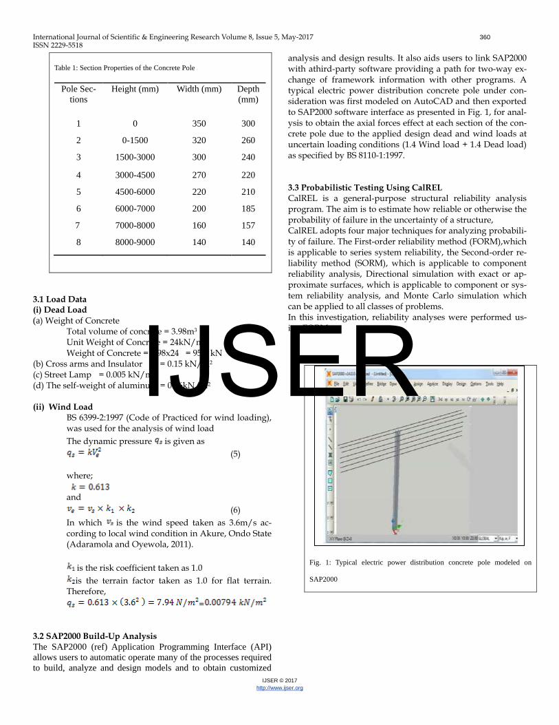
analysis and design results. It also aids users to link SAP2000 with athird-party software providing a path for two-way ex-change of framework information with other programs. A typical electric power distribution concrete pole under con-sideration was first modeled on AutoCAD and then exported to SAP2000 software interface as presented in Fig. 1, for anal-ysis to obtain the axial forces effect at each section of the con-crete pole due to the applied design dead and wind loads at uncertain loading conditions (1.4 Wind load + 1.4 Dead load) as specified by BS 8110-1:1997. 3.3 Probabilistic Testing Using CalREL CalREL is a general-purpose structural reliability analysis program. The aim is to estimate how reliable or otherwise the probability of failure in the uncertainty of a structure, CalREL adopts four major techniques for analyzing probabili-ty of failure. The First-order reliability method (FORM),which is applicable to series system reliability, the Second-order re-liability method (SORM), which is applicable to component reliability analysis, Directional simulation with exact or ap-proximate surfaces, which is applicable to component or sys-tem reliability analysis, and Monte Carlo simulation which can be applied to all classes of problems. In this investigation, reliability analyses were performed us-ing FORM.
Fig. 1: Typical electric power distribution concrete pole modeled on
SAP2000
IJSER
International Journal of Scientific & Engineering Research Volume 8, Issue 5, May-2017 361 ISSN 2229-5518
IJSER © 2017 http://www.ijser.org
Table 2: The Limit State Function
Parameter Assumed Distribu-
tion
Coefficient of Varia-tion (%)
Breadth Normal 10 Depth Normal 10
Characteristic concrete
strength (fcu)
Log Normal
30
Characteristic steel strength
(fy)
Log Normal
30
Reinforcement ratio (ρ)
Normal 10
Axial Force (F) Log Normal
30
The difference between the resistance of the concrete pole and the applied load effect is the limit state function as given in equation (1) The load combination for the ultimate limit state at adverse level from BS 8110-1: 1997 is given as; W=1.4Gk + 1.4Wk (9) The Axial force capacity for the compressive section is given as;
(10) In which At the ultimate limit state, . Thus,
(11) The Axial force capacity for the tension section is given as;
(12) Hence,
(13) The percentage reinforcement ratio (ρ) was varied from the minimum of 0.55% to maximum of 3.00% with an interval of 0.55. From equation (11) and (13), the axial forces capacity is a function of the breath, effective depth, characteristics strength of concrete and steel, lever arm and the area of steel provided. The statistical data adopted for the analyses are as presented in Table 2. 3.4 Discussion of Modes of failure The safety of a structure can be menstruated in terms of relia-bility index, β, or otherwise, its failure can by assessed by probability of failure, . Probabilistic assessments were ex-ecuted for electric power distribution concrete poles based on the extrapolated limit state equations. The results derived from reliability evaluation are discussed.
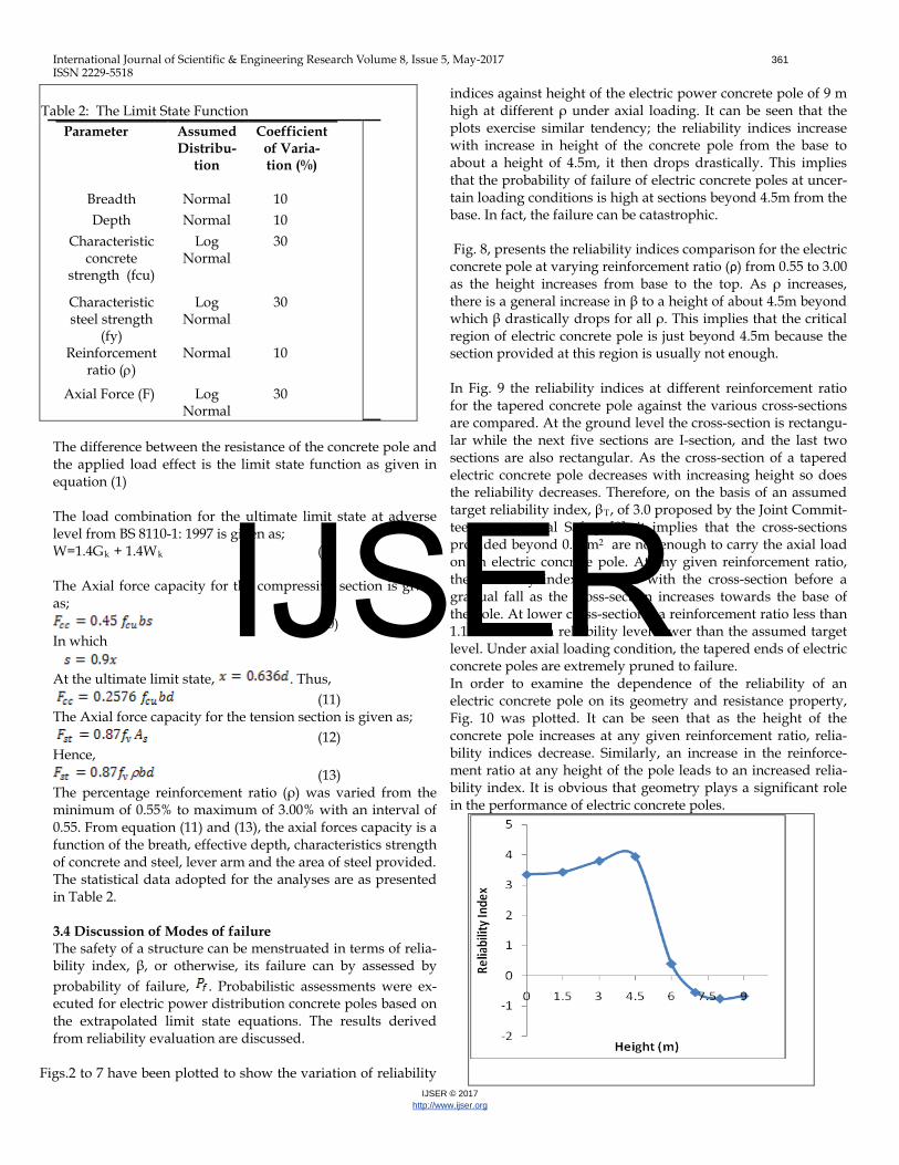
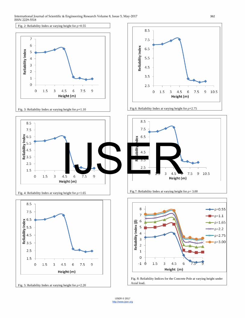
Figs.2 to 7 have been plotted to show the variation of reliability
indices against height of the electric power concrete pole of 9 m high at different ρ under axial loading. It can be seen that the plots exercise similar tendency; the reliability indices increase with increase in height of the concrete pole from the base to about a height of 4.5m, it then drops drastically. This implies that the probability of failure of electric concrete poles at uncer-tain loading conditions is high at sections beyond 4.5m from the base. In fact, the failure can be catastrophic.
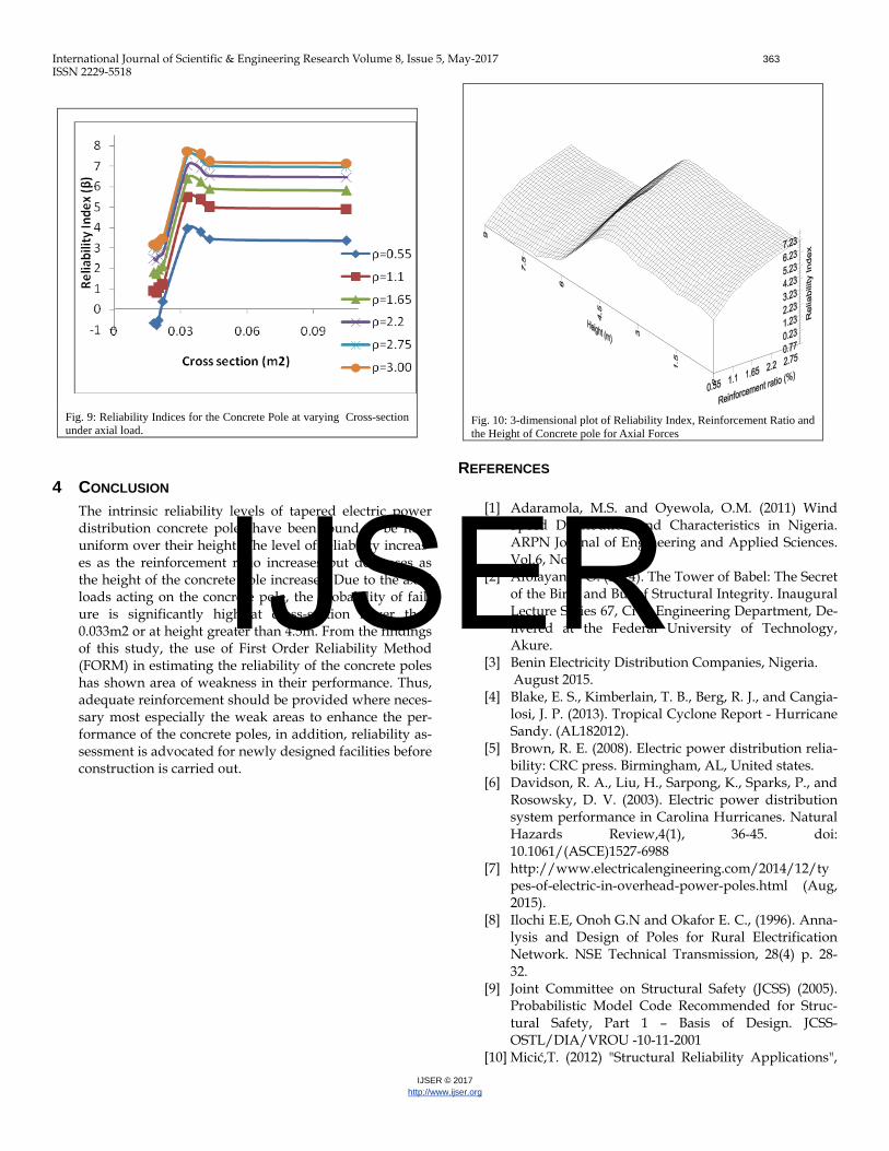
Fig. 8, presents the reliability indices comparison for the electric concrete pole at varying reinforcement ratio (ρ) from 0.55 to 3.00 as the height increases from base to the top. As ρ increases, there is a general increase in β to a height of about 4.5m beyond which β drastically drops for all ρ. This implies that the critical region of electric concrete pole is just beyond 4.5m because the section provided at this region is usually not enough. In Fig. 9 the reliability indices at different reinforcement ratio for the tapered concrete pole against the various cross-sections are compared. At the ground level the cross-section is rectangu-lar while the next five sections are I-section, and the last two sections are also rectangular. As the cross-section of a tapered electric concrete pole decreases with increasing height so does the reliability decreases. Therefore, on the basis of an assumed target reliability index, βT, of 3.0 proposed by the Joint Commit-tee on structural Safety [9], it implies that the cross-sections provided beyond 0.03m2 are not enough to carry the axial load on an electric concrete pole. At any given reinforcement ratio, the reliability index increases with the cross-section before a gradual fall as the cross-section increases towards the base of the pole. At lower cross-sections, a reinforcement ratio less than 1.1 will lead to a reliability level lower than the assumed target level. Under axial loading condition, the tapered ends of electric concrete poles are extremely pruned to failure. In order to examine the dependence of the reliability of an electric concrete pole on its geometry and resistance property, Fig. 10 was plotted. It can be seen that as the height of the concrete pole increases at any given reinforcement ratio, relia-bility indices decrease. Similarly, an increase in the reinforce-ment ratio at any height of the pole leads to an increased relia-bility index. It is obvious that geometry plays a significant role in the performance of electric concrete poles.
IJSER
International Journal of Scientific & Engineering Research Volume 8, Issue 5, May-2017 362 ISSN 2229-5518
IJSER © 2017 http://www.ijser.org
Fig. 2: Reliability Index at varying height for ρ=0.55
Fig. 3: Reliability Index at varying height for ρ=1.10
Fig. 4: Reliability Index at varying height for ρ=1.65
Fig. 5: Reliability Index at varying height for ρ=2.20
Fig.6: Reliability Index at varying height for ρ=2.75
Fig.7: Reliability Index at varying height for ρ= 3.00
Fig. 8: Reliability Indices for the Concrete Pole at varying height under Axial load.
IJSER
International Journal of Scientific & Engineering Research Volume 8, Issue 5, May-2017 363 ISSN 2229-5518
IJSER © 2017 http://www.ijser.org
Fig. 9: Reliability Indices for the Concrete Pole at varying Cross-section under axial load.
4 CONCLUSION The intrinsic reliability levels of tapered electric power distribution concrete poles have been found to be non-uniform over their height. The level of reliability increas-es as the reinforcement ratio increases but decreases as the height of the concrete pole increases. Due to the axial loads acting on the concrete pole, the probability of fail-ure is significantly high at cross-section lower than 0.033m2 or at height greater than 4.5m. From the findings of this study, the use of First Order Reliability Method (FORM) in estimating the reliability of the concrete poles has shown area of weakness in their performance. Thus, adequate reinforcement should be provided where neces-sary most especially the weak areas to enhance the per-formance of the concrete poles, in addition, reliability as-sessment is advocated for newly designed facilities before construction is carried out.
Fig. 10: 3-dimensional plot of Reliability Index, Reinforcement Ratio and the Height of Concrete pole for Axial Forces
REFERENCES
[1] Adaramola, M.S. and Oyewola, O.M. (2011) Wind Speed Distribution and Characteristics in Nigeria. ARPN Journal of Engineering and Applied Sciences. Vol.6, No2.
[2] Afolayan, J. O. (2014). The Tower of Babel: The Secret of the Birth and But of Structural Integrity. Inaugural Lecture Series 67, Civil Engineering Department, De-livered at the Federal University of Technology, Akure.
[3] Benin Electricity Distribution Companies, Nigeria. August 2015.
[4] Blake, E. S., Kimberlain, T. B., Berg, R. J., and Cangia-losi, J. P. (2013). Tropical Cyclone Report - Hurricane Sandy. (AL182012).
[5] Brown, R. E. (2008). Electric power distribution relia-bility: CRC press. Birmingham, AL, United states.
[6] Davidson, R. A., Liu, H., Sarpong, K., Sparks, P., and Rosowsky, D. V. (2003). Electric power distribution system performance in Carolina Hurricanes. Natural Hazards Review,4(1), 36-45. doi: 10.1061/(ASCE)1527-6988
[7] http://www.electricalengineering.com/2014/12/types-of-electric-in-overhead-power-poles.html (Aug, 2015).
[8] Ilochi E.E, Onoh G.N and Okafor E. C., (1996). Anna-lysis and Design of Poles for Rural Electrification Network. NSE Technical Transmission, 28(4) p. 28-32.
[9] Joint Committee on Structural Safety (JCSS) (2005). Probabilistic Model Code Recommended for Struc-tural Safety, Part 1 – Basis of Design. JCSS-OSTL/DIA/VROU -10-11-2001
[10] Micić,T. (2012) "Structural Reliability Applications",
IJSER
International Journal of Scientific & Engineering Research Volume 8, Issue 5, May-2017 364 ISSN 2229-5518
IJSER © 2017 http://www.ijser.org
Lectures on Faculty of Civil Engineering and Archi-tecture in University of Niš, Serbia,
[11] Oliphant, W. and Wong, C. (2002), “Spun Concrete Poles for Electrical Transmission Structure Applica-tions - Continuing to Push the Envelope of the Tech-nology,” Electrical Transmission in a New Age, 241-248.
[12] Opeyemi, D. A. (2012). Stochastic Modelling of Struc-tural Elements. In: Ivanov, I. G. (Ed.), Stochastic Modeling and Control, Intech. Retrieved from. http;//www.interchopen.com/books/stochastic-modeling-and-control/stochastic-modelling-of-structural-elements. Aug, 2014.
[13] Quadri, A.I and Afolayan, J.O. (2016) “Probabilistic-Based Assessment of Electric power Distribution Concrete Poles in Southwest of Nigeria”. Interna-tional Journal of Advanced Science and Research Management (IJARSM). Vol. 1 No. 10 pp 102-110
[14] Short, T. A. (2006). Electric Power Distribution Equipment and Systems. Boca Raton, FL: CRC Press. North.
[15] Thomas E.,and Rodgers, J.R (1984), “Prestressed Concrete Poles: A State-of-the-Art Report,” Pre-stressed Concrete Institute (PCI) issue of the PCI Journal.America.
[16] Willis, H. L., and Philipson, L. (2005). Understanding electric utilities and de-regulation (Vol. 27): CRC Press.North America.
[17] Yao, J. T. P., and Kawamura, H. (2001). On Structural Reliability. Journal of Temporal Design in Architec-ture and the Environment, 1(1), 1-5.
IJSER