Embed Size (px)
Citation preview
TECHNICAL SPECIFICATION No. I-ET-3010.00-1200-955-P4X-001
CLIENT: SHEET: 1 of 68
PROJECT:
CC:
AREA: -
DP&T-SUP
TITLE:
WELDING NP-1
ESUP
MICROSOFT WORD / V.2013 / I-ET-3010.00-1200-955-P4X-001_0.DOCX
INDEX OF REVISIONS
REV. DESCRIPTION AND/OR REVISED SHEETS
0
ORIGINAL
REV. 0 REV. A REV. B REV. C REV. D REV. E REV. F REV. G REV. H
DATE AUG/28/18
DESIGN ESUP
EXECUTION MARCHON
CHECK MARIANO
APPROVAL JUVENTINO
INFORMATION IN THIS DOCUMENT IS PROPERTY OF PETROBRAS, BEING PROHIBITED OUTSIDE OF THEIR PURPOSE.
FORM OWNED TO PETROBRAS N-381 REV. L.
PRELIMIN
ARY
TECHNICAL SPECIFICATION Nº:
I-ET-3010.00-1200-955-P4X-001 REV.
0
AREA: SHEET 2 of 68
TITLE:
WELDING NP-1
ESUP
SUMMARY
TABLE OF CONTENTS
1 INTRODUCTION ............................................................................................................................................ 3
2 NORMATIVE REFERENCES ....................................................................................................................... 3
2.1 CLASSIFICATION .............................................................................................................................................. 3 2.2 CODES AND STANDARDS ............................................................................................................................... 3 2.3 REFERENCE DOCUMENTS .............................................................................................................................. 5 2.4 CONFLICTING REQUIREMENTS .................................................................................................................... 5
3 DEFINITIONS AND ABBREVIATIONS ..................................................................................................... 6
3.1 REQUIREMENTS AND RECOMMENDATIONS ............................................................................................. 6 3.2 DEFINITIONS ..................................................................................................................................................... 6 3.3 ABBREVIATIONS .............................................................................................................................................. 7
4 QUALITY REQUIREMENTS ....................................................................................................................... 8
5 MATERIALS ................................................................................................................................................... 8
5.1 CARBON STEEL, CARBON-MANGANESE STEEL, LOW ALLOY STEEL AND HIGH-STRENGTH, LOW-
ALLOY (HSLA) STEEL. ........................................................................................................................................... 8 5.2 WELDING OF DUPLEX AND SUPERDUPLEX STAINLESS STEEL ............................................................. 9 5.3 WELDING OF NICKEL ALLOY STEEL .......................................................................................................... 16 5.4 COPPER AND COPPER ALLOYS .................................................................................................................... 23 5.5 INCONEL ........................................................................................................................................................... 26 5.6 AUSTENITIC STAINLESS STEELS ................................................................................................................ 29 5.7 WELDING OF INCONEL 625 “WELD OVERLAY” CLAD PIPE ................................................................... 35 5.8 WELDING OF OTHER METALS AND ALLOYS ........................................................................................... 44
ANNEX A (INFORMATIVE-NONMANDATORY) .......................................................................................... 45
ANNEX B (INFORMATIVE-NONMANDATORY)........................................................................................... 47
ANNEX C (INFORMATIVE-NONMANDATORY) .......................................................................................... 48
ANNEX D (MANDATORY).................................................................................................................................. 49
ANNEX E (RECOMMENDATION - NONMANDATORY) ............................................................................. 52
ANNEX F (MANDATORY) .................................................................................................................................. 53
ANNEX G (MANDATORY) ................................................................................................................................. 57
ANNEX H (MANDATORY) ................................................................................................................................. 58
ANNEX I (MANDATORY) ................................................................................................................................... 59
ANNEX J (MANDATORY) .................................................................................................................................. 61
ANNEX K (MANDATORY) ................................................................................................................................. 64
ANNEX L (MANDATORY) .................................................................................................................................. 67
ANNEX M (MANDATORY) ................................................................................................................................. 68
PRELIMIN
ARY
TECHNICAL SPECIFICATION Nº:
I-ET-3010.00-1200-955-P4X-001 REV.
0
AREA: SHEET 3 of 68
TITLE:
WELDING NP-1
ESUP
1 INTRODUCTION
This technical specification, in addition to other specifications and codes referred to in Section 2, defines the requirements for the welding for all offshore topside, hull, marine and production parts, including but not limited to equipment, both static and dynamic, structures and piping.
The requirements herein listed shall be applied along with all the requirements from the applicable design codes, so that the most stringent requirement shall always prevail.
2 NORMATIVE REFERENCES
All equipment shall comply with the requirements of this technical specification, data sheets, documents as stated below and with those referred to herein.
2.1 CLASSIFICATION
MANUFACTURER/PACKAGER shall perform the work in accordance with the requirements of Classification Society.
2.2 CODES AND STANDARDS
The following codes and standards include provisions which, through reference in this text, constitute provisions of this specification. The latest issue of the references shall be used unless otherwise agreed. Other recognized standards may be used, provided it can be shown that they meet or exceed the requirements of the standards referenced below.
Note: The Standards referred herein shall be considered in their latest edition/revision.
API RP 578 – Guidelines for a Material Verification Program for New and Existing Assets;
API RP 582 – Welding Guidelines for the Chemical, Oil, and Gas Industries;
API 6A/ISO 10423 – Specification for Wellhead and Christmas Tree Equipment;
API 5L – Line Pipe;
ASME B 31.3 – Process Piping;
ASME B 31.4 – Pipeline Transportation Systems for Liquid Hydrocarbons and Other Liquids (only topside interface at pig launcher and receiver system);
ASME B 31.8 – Gas Transmission Distribution and Piping Systems (only topside interface at pig launcher and receiver system);
ASME B16.25 – Buttwelding Ends;
ASME BPVC Section II, Part C – Welding Rods, Electrodes and Filler Metals;
ASME BPVC Section VIII – Rules for Construction of Pressure Vessels;
ASME BPVC Section IX – Welding and Brazing Qualification;
ASTM A370 – Standard Test Methods and Definitions for Mechanical Testing of Steel Products.
ASTM A380 – Standard Practice for Cleaning, Descaling, and Passivation of Stainless Steel Parts, Equipment, and Systems;
ASTM A923 – Standard Test Methods for Detecting Detrimental Intermetallic Phase in Duplex Austenitic/Ferritic Stainless Steel.
ASTM E92 – Standard Test Method for Vickers Hardness and Knoop Hardness of Metallic Materials;
ASTM E10 – Standard Test Method for Brinell Hardness of Metallic Materials;
ASTM E112 – Standard Test Methods for Determining Average Grain Size;
ASTM E165 – Standard Practice for Liquid Penetrant Examination for General Industry;
ASTM E384 – Standard Test Method for Microindentation Hardness of Materials;
ASTM E407 – Standard Practice Microetching Metals and Alloys;
ASTM E562 – Standard Test Method for Determining Volume Fraction by Systematic Manual Point Count;
PRELIMIN
ARY
TECHNICAL SPECIFICATION Nº:
I-ET-3010.00-1200-955-P4X-001 REV.
0
AREA: SHEET 4 of 68
TITLE:
WELDING NP-1
ESUP
ASTM G48 – Standard Test Methods for Pitting and Crevice Corrosion Resistance of Stainless Steels and Related Alloys by Use of Ferric Chloride Solution;
ASTM E527 – Standard Practice for Numbering Metals and Alloys in the Unified Numbering System (UNS);
AWS A3.0 – Standard Welding Terms and Definitions;
AWS C5.5 – Recommended Practices for Gas Tungsten Arc Welding
ASME/AWS A5.01 – Welding Consumables – Procurement of Filler Metal and Fluxes;
ASME/AWS A5.1 – Specification for Carbon Steel Electrodes for Shielded Metal Arc Welding;
ASME/AWS A5.4 – Specification for Stainless Steel Electrodes for Shielded Metal Arc Welding;
ASME/AWS A5.5 – Specification for Low-Alloy Steel Electrodes for Shielded Metal Arc Welding;
ASME/AWS A5.7 – Specification for Copper and Copper-Alloy Bare Welding Rods and Electrodes;
ASME/AWS A5.9 – Specification for Bare Stainless Steel Welding Electrodes and Rods;
ASME/AWS A5.11 – Specification for Nickel and Nickel-Alloy Welding Electrodes for Shielded Metal Arc Welding;
ASME/AWS A5.14 – Specification for Nickel and Nickel-Alloy Bare Welding Electrodes and Rods;
ASME/AWS A5.16 – Specification for Titanium and Titanium-Alloy Welding Electrodes and Rods;
ASME/AWS A5.17 – Specification for Carbon Steel Electrodes and Fluxes for Submerged Arc Welding;
ASME/AWS A5.18 – Specification for Carbon Steel Electrodes and Rods for Gas Shielded Arc Welding;
ASME/AWS A5.23 – Specification for Low-Alloy Steel Electrodes and Fluxes for Submerged Arc Welding;
ASME/AWS A5.26 – Specification for Carbon and Low-Alloy Steel Electrodes and Electrogas Welding;
ASME/AWS A5.28 – Specification for Low-Alloy Steel Electrodes and Rods for Gas Shielded Arc Welding;
ASME/AWS A5.29 – Specification for Low-Alloy Steel Electrodes for Flux Cored Arc Welding;
ASME/AWS A5.30 – Specification for Consumable Inserts;
ASME/AWS A5.36 – Specification for Carbon and Low-Alloy Steel Flux Cored Electrodes for Flux Cored Arc Welding and Metal Cored Electrodes for Gas Metal Arc Welding;
AWS D1.1 – Structural Welding Code – Steel;
AWS D10.10 – Recommended Practices for Local Heating of Welds in Piping and Tubing;
AWS D10.18 – Guide for Welding Ferritic/Austenitic Duplex Stainless Steel Piping and Tubing;
BS PD 5500 – Specification for Unfired Fusion Welded Pressure Vessels;
ISO 5173 – Destructive Tests on Welds in Metallic Materials – Bend Tests;
ISO 5817 – Welding – Fusion-welded Joints in Steel, Nickel, Titanium and Their Alloys (beam welding excluded) – Quality Levels for Imperfections;
ISO 6847 – Welding Consumables – Deposition of a Weld Metal Pad for Chemical Analysis;
ISO 6947 – Welding and Allied Processes-Welding Positions;
ISO 8249 - Welding — Determination of Ferrite Number (FN) in austenitic and duplex ferritic-austenitic Cr-Ni stainless steel weld metals
ISO 14175 – Welding Consumables – Gases and Gas Mixtures for Fusion Welding and Allied Processes;
ISO 15156 Parts 1-3 – Petroleum and Natural Gas Industries – Materials for Use in H2S-Containing Environments in Oil and Gas Production;
ISO 15614 – Specification and Qualification of Welding Procedures for Metallic Materials – Welding Procedure Test – Part 5: Arc Welding of Titanium, Zirconium and Their Alloys;
ISO 15614 – Specification and Qualification of Welding Procedures for Metallic Materials – Welding Procedure Test – Part 7: Overlay Welding;
PRELIMIN
ARY
TECHNICAL SPECIFICATION Nº:
I-ET-3010.00-1200-955-P4X-001 REV.
0
AREA: SHEET 5 of 68
TITLE:
WELDING NP-1
ESUP
ISO 17025 – General Requirements for the Competence of Testing and Calibration Laboratories;
ISO 17637 – Non-Destructive Testing of Welds – Visual Testing of Fusion-Welded Joints;
ISO 3834-2 – Quality Requirements for Fusion Welding of Metallic Materials - Part 2: Comprehensive Quality Requirements;
ISO 15590-1 – Induction Bending;
ISO-8501-1 – Preparation of Steel Substrates Before Application of Paints and Related Products – Visual Assessment of Surface Cleanliness;
NORSOK M-601 – Welding and Inspection of Piping.
Governmental codes, regulations, ordinances or rules applicable to the equipment in Brazil shall prevail over the requirements of above specification, including reference codes and standards and/or these engineering specifications, only in those cases where they are more stringent.
2.3 REFERENCE DOCUMENTS
I-ET-Requirements for Welding Inspection (as applicable to the project)
I-ET-0000.00-0000-970-PSQ-001 – Procedure and Personnel Qualification and Certification
2.4 CONFLICTING REQUIREMENTS
In case of conflicting information between this Technical Specification (hereinafter called ET) and the referred applicable standards, the most stringent requirement shall prevail.
In case of conflicting information between this ET and other specific PURCHASER’s Document (Data Sheet or Equipment List) see the document basic design documentation priority guidelines, if applicable.
PRELIMIN
ARY
TECHNICAL SPECIFICATION Nº:
I-ET-3010.00-1200-955-P4X-001 REV.
0
AREA: SHEET 6 of 68
TITLE:
WELDING NP-1
ESUP
3 DEFINITIONS AND ABBREVIATIONS
3.1 REQUIREMENTS AND RECOMMENDATIONS
Whenever used the term “Shall” in this technical document, it is intended that what is stated is an absolute requirement. Non-compliance to shall requirements shall be formally accepted by PETROBRAS.
Whenever used the term “Should” in this technical document, it is intended that what is stated is a recommendation. Alternative solutions having the same functionality and quality are acceptable provided that alternative solution had been submitted to PETROBRAS and received its approval.
Whenever used the term “May” in this technical document, it is intended that what is stated is an indication of a course of action permissible within the limits of this technical specification.
3.2 DEFINITIONS
Terms used in this Technical Specification shall be interpreted in accordance with AWS A3.0 (Standard Welding Terms and Definitions), except for those not defined on that standard or where these terms require further definition to clarify their usage in this Technical Specification, like:
Purchaser: The party that issues the purchase order. This may be the user or owner of the equipment/pipe, or the PETROBRAS’s designated agent (e.g., engineering contractors).
Manufacturer/Packager: the party that purchases the welding consumables and performs all welding tasks and to whom the welding project has been contracted.
Applicable code or standard: The code or standard specified by the PETROBRAS to which the equipment/pipe shall conform.
Jig: “mold” or pattern made for repetitive layouts requiring same measurements.
Weld maps: The document which identifies the welding procedure specification (WPS) to be used for specific weld joint.
Welding procedure qualification records (PQR): The PQR is a record of the welding data and variables used to weld a test coupon and the test results used to qualify the welding procedure. The purpose of the PQR is to establish the properties of the weldment.
Welding Procedure Specifications (WPS): The WPS provides direction to the welder while making production welds to applicable code requirements.
Welding Material Control Center: A specific area within the Workshop where welding materials are to be stored in isolation from other goods in accordance with the requirements listed in this Technical Specification.
Clad: Coating of corrosion resistance alloy (CRA) metallurgical bonding to carbon steel base metal, to improve its corrosion resistance.
Clad coating process: Any process that can assure a metallurgical bond between CRA to carbon steel base metal. The list of cladding process is shown below.
Roll bonding: a clad coating process that bonds two metallic plates, heated to suitable temperature, by a pressure developed in a rolling mill.
Explosive bonding: a clad coating process that bonds two metallic plates by a high pressure developed by a chemical explosive.
PRELIMIN
ARY
TECHNICAL SPECIFICATION Nº:
I-ET-3010.00-1200-955-P4X-001 REV.
0
AREA: SHEET 7 of 68
TITLE:
WELDING NP-1
ESUP
Weld overlay bonding: a clad coating process that deposit a CRA on the surface a carbon steel by a welding process.
Duplex stainless steel: General designation for austenitic-ferritic stainless steels. It encompasses both the ferritic/austenitic stainless steel alloys with 22% Cr (also known as duplex stainless steels) and the ferritic/austenitic stainless steel alloys with 25% Cr (also known as Superduplex stainless steels).
3.3 ABBREVIATIONS
CS Carbon Steels CMn Carbon-Manganese (Steels) CE Carbon Equivalent CRA Corrosion Resistant Alloy CVN Charpy V-Notch FCAW Flux Cored Arc Welding GTAW Gas Tungsten Arc Welding GMAW Gas Metal Arc welding HAZ Heat Affected Zone MT Magnetic Particle Testing NDT Non-Destructive Testing PLEM Pipe Line End Manifold P & ID Piping and Instrument Diagram PRE Pitting Resistance Equivalent PT Liquid Penetrant Testing (Dye Penetrant Testing) PWHT Postweld Heat Treatment RT Radiographic Testing SAW Submerged Arc Welding SMAW Shielded Metal Arc-Welding UNS Unified Numbering System for Metals and Alloys (according to ASTM E527) UT Ultrasonic Testing PWPS Preliminary Welding Procedure Specification
PRELIMIN
ARY
TECHNICAL SPECIFICATION Nº:
I-ET-3010.00-1200-955-P4X-001 REV.
0
AREA: SHEET 8 of 68
TITLE:
WELDING NP-1
ESUP
4 QUALITY REQUIREMENTS
MANUFACTURER must develop and implement a comprehensive quality system for fusion welding of metallic materials both in workshops and at field installation sites in accordance with ISO 3834-2.
Welding shall as a minimum be performed in accordance with API 582 with the additional requirements herein listed.
Personnel and procedure qualification for welding and for NDT shall be in accordance with I-ET-0000.00-0000-970-PSQ-001.
Where sour service is applicable, materials and all welding procedures shall also fulfill the requirements of the applicable section of ISO 15165.
Positive Material Identification (PMI), when required, shall be performed in accordance with API RP 578.
Magnetic tests performed in order to evaluate phase balance (Ferrite Number evaluation) shall be performed in accordance with ISO 8249.
5 MATERIALS
5.1 CARBON STEEL, CARBON-MANGANESE STEEL, LOW ALLOY STEEL AND HIGH-
STRENGTH, LOW-ALLOY (HSLA) STEEL.
Carbon steel materials shall be welded in accordance with the requirements of API 582, with procedures being qualified in accordance with the applicable design code.
Where sour service is applicable, materials and welding procedures shall meet all the requirements from ISO 15156-1.
When qualifying weld procedures for high strength pipe components (API 5L X56 and above, as well as the equivalent material specifications for accessories, such as ASTM F694 Grade F56 and above) the qualification test piece shall use as base material the exact same strength grade as will be used in production welding.
Preheat for welding of metallic structures shall be determined in accordance with AWS D1.1, Annex I.
PRELIMIN
ARY
TECHNICAL SPECIFICATION Nº:
I-ET-3010.00-1200-955-P4X-001 REV.
0
AREA: SHEET 9 of 68
TITLE:
WELDING NP-1
ESUP
5.2 WELDING OF DUPLEX AND SUPERDUPLEX STAINLESS STEEL
5.2.1 Introduction
Under certain conditions, Duplex Stainless Steel (DSS) and Super Duplex Stainless Steel (SDSS) replace austenitic stainless steels of the 300 series due to its good relationship between mechanical strength and resistance to corrosion, such as stress corrosion cracking, "pitting", and crevice, especially due to the addition of nitrogen. Two other properties are important for the welding: thermal expansion coefficient comparable to that of carbon steels, and higher thermal conductivity than austenitic stainless steel.
DSS and SDSS shall not be exposed to operating temperature above 250ºC due to the precipitation of deleterious phases that lead to the reduction of corrosion resistance, ductility and toughness.
The base metal has microstructure composed of about 50% ferrite and 50% austenite, however, the ferrite content in the melt zone may vary from 35% to 65%.
Throughout its evolution these stainless steels have been commercially referenced three ways: duplex, superduplex and hiperduplex. All feature austenitic-ferritic structure. Basically the difference between them is the amount of number of Resistance Equivalent "Pitting" (PREN).
Currently the classification of different degrees based on the chemical composition and PREN, is in accordance with one of the following formulas:
PRENN = %Cr + 3,3(%Mo) + 16(%N)
PRENW = %Cr + 3,3(%Mo + 0,5 %W) + 16(%N)
Note: Both expressions have been used and cater respectively to steels without and with W.
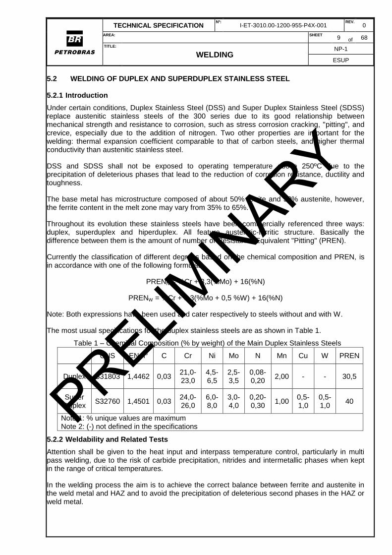
The most usual specifications for the duplex stainless steels are as shown in Table 1.
Table 1 – Chemical Composition (% by weight) of the Main Duplex Stainless Steels
UNS EN n° C Cr Ni Mo N Mn Cu W PREN
Duplex S31803 1,4462 0,03 21,0-23,0
4,5-6,5
2,5-3,5
0,08-0,20
2,00 - - 30,5
Super Duplex
S32760 1,4501 0,03 24,0-26,0
6,0-8,0
3,0-4,0
0,20-0,30
1,00 0,5-1,0
0,5-1,0
40
Note 1: % unique values are maximum Note 2: (-) not defined in the specifications
5.2.2 Weldability and Related Tests
Attention shall be given to the heat input and interpass temperature control, particularly in multi pass welding, due to the risk of carbide precipitation, nitrides and intermetallic phases when kept in the range of critical temperatures.
In the welding process the aim is to achieve the correct balance between ferrite and austenite in the weld metal and HAZ and to avoid the precipitation of deleterious second phases in the HAZ or weld metal.
PRELIMIN
ARY
TECHNICAL SPECIFICATION Nº:
I-ET-3010.00-1200-955-P4X-001 REV.
0
AREA: SHEET 10 of 68
TITLE:
WELDING NP-1
ESUP
Before welding all base metals must be checked for their chemical composition (100% PMI testing) and for their correct phase balance (100% magnetic testing). Hardness testing shall be performed when sour service is applicable (as required by ISO 15156-3).
On the qualification of the welding procedure the tests shall be as determined in Table 3. The requirements of ASTM A923 must be met in order to verify the presence of intermetallic phases.
Production welds shall be checked for its chemical composition (100% PMI testing) and for its phase balance (100% magnetic testing). Hardness testing shall be performed on production welds when sour service is applicable. These tests shall be performed in the deposited weld metal and on the Heat Affected Zone (HAZ).
The use of consumables with higher Ni content may grant weld metal properties compatible with the base metal. Welding with consumables with a chemical composition that matches the one from the base materials is allowed only when the full welded piece is submitted to a full anneal heat treatment after welding, so that the phase balance is restored in the whole piece.
5.2.3 General Welding Technique
The manufacture of pipes and equipment in stainless steels shall be done in segregated and protected area, preferably in a separate workshop. DSS and SDSS must be clearly segregated from austenitic stainless steels during manufacture.
The welding preparation can be made through the use of cold cutting, abrasive cutting, milling, water jet cutting, machining, plasma or laser cutting. In plasma cutting, depending on the quality required for the cutting, Ar or Ar + H2 mixture may be used with the following combinations 85/15%, 80/20%, and 65/35%. A higher H2 content will help increase the arc energy resulting in higher cutting speeds and / or larger cutting thicknesses. After the thermal cutting, the ends shall be trimmed in 1.0 mm at least. Thermal cuts with graphite and oxyfuel are not allowed.
Also due to the higher viscosity of stainless steel weld puddle in relation to C-Mn steels, the preparation shall consider higher joint angle than for those steels, minimizing the risk of lack of fusion.
The preparation and cleaning must consider a range of 50 mm for both sides of the joint. This area must be cleaned by grinding and solvent to remove grease, oxides, paint markers and other contaminants that may be harmful to welding.
The tools for slag removal, cleaning and cutting must be used exclusively for these materials and meet the following requirements:
a) Tools for slag removal and cleaning shall be stainless steel or coated with this material;
b) Cutting discs and grinding must be made of aluminum oxide with soul "Nylon" or fiberglass;
c) Additional precautions must be taken to avoid contamination of the joints during preparation.
It is recommended that the surface of the parts is protected against spatter and other projections
resulting from welding, especially when it is used the GMAW process. [Recommended Practice]
Consumables (wires, rods and electrodes) shall be properly stored in clean, dry place and always handled with clean gloves. The wires shall be cleaned with solvents before use.
The use of spot welding and auxiliary assembly devices shall be detailed in the welding procedure to be submitted for prior approval of PETROBRAS, including the specification of materials to be used in the manufacture of device and consumables for the weld
PRELIMIN
ARY
TECHNICAL SPECIFICATION Nº:
I-ET-3010.00-1200-955-P4X-001 REV.
0
AREA: SHEET 11 of 68
TITLE:
WELDING NP-1
ESUP
The part of the auxiliary assembly device in contact or welded to piping shall be of the same P number of the base metal (in accordance with the classification of BPVC ASME Section IX) or, alternatively, covered with specified consumable welding metal with at least two layers.
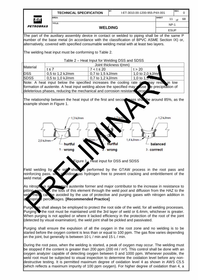
The welding heat input must be conforming to Table 2.
Table 2 – Heat Input for Welding DSS and SDSS
Material Joint thickness t(mm)
t ≤ 7 7 < t ≤ 20 t > 20
DSS 0,5 to 1,2 kJ/mm 0,7 to 1,5 kJ/mm 1,0 to 2,0 kJ/mm
SDSS 0,5 to 1,0 kJ/mm 0,7 to 1,2 kJ/mm 1,0 to 1,5 kJ/mm
Note: A heat input below the specified increases the cooling rate and may result in low formation of austenite. A heat input welding above the specified may cause the precipitation of deleterious phases, reducing the mechanical and corrosion resistance properties
The relationship between the heat input of the first and second pass shall be around 85%, as the example shown in Figure 1.
Figure 1 - Heat input for DSS and SDSS
Field welding by one side shall be performed by the GTAW process in the root pass and reinforcing pass, with shielding gas hydrogen free to prevent cracking and embrittlement of the weld metal.
As nitrogen is an important austenite former and major contributor to the increase in resistance to pitting corrosion, the loss of this element through the weld pool and diffusion from the HAZ to the weld metal can be avoided by the use of protective and purging gases with nitrogen addition in
appropriate percentages. [Recommended Practice]
Purge gas shall always be employed to protect the root side of the weld, for all welding processes. Purging in the root must be maintained until the 3rd layer of weld or 6.4mm, whichever is greater. When purging is not applied or where it lacked efficiency in the protection of the root of the joint (detected by visual examination), the weld joint shall be pickled and passivated.
Purging shall ensure the expulsion of all the oxygen in the root zone and no welding is to be started before the oxygen content is less than or equal to 100 ppm. The gas flow varies depending on the joint, but generally is between 10 L / min and 15 L / min.
During the root pass, when the welding is started, a peak of oxygen may occur. The welding must be stopped if the content is greater than 200 ppm (200 ml / m³). This control shall be done with an oxygen analyzer capable of detecting oxygen between 0 and 1000 ppm. Whenever possible, the weld root must be subjected to visual inspection to determine the oxidation level before any non-destructive testing. It is permitted maximum degree of oxidation level 4 as shown in AWS C5.5 (which reflects a maximum impurity of 100 ppm oxygen). For higher degree of oxidation than 4, a
PRELIMIN
ARY
TECHNICAL SPECIFICATION Nº:
I-ET-3010.00-1200-955-P4X-001 REV.
0
AREA: SHEET 12 of 68
TITLE:
WELDING NP-1
ESUP
passivation shall be conducted immediately after grinding or etching. The pickling and passivation shall be according ASTM A380.
NOTE: For pieces with thickness less than 6.4 mm internal purge shall be carried out even for the welding of external component, such as supports, spouts, and so on.
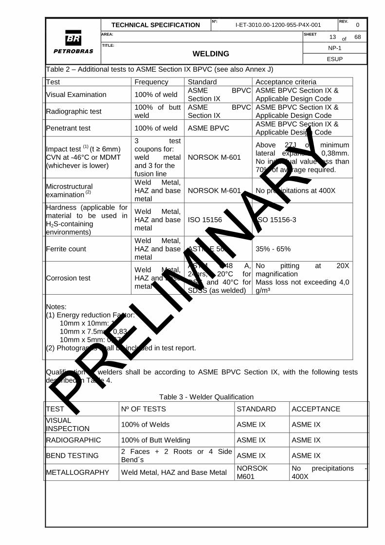
In the qualification of welding procedures, the following aspects shall be considered in addition to the ASME BPVC Section IX requirements: radiographic test, liquid penetrant test, impact test, microstructural examination for precipitates, corrosion testing for pitting susceptibility, and weld ferrite counting, as described in Table 3.
The hardness of the HAZ after welding shall not exceed the maximum hardness allowed for the base metal, and the hardness of the weld metal shall not exceed the maximum hardness limit of the respective alloy used for the welding consumable.
PRELIMIN
ARY
TECHNICAL SPECIFICATION Nº:
I-ET-3010.00-1200-955-P4X-001 REV.
0
AREA: SHEET 13 of 68
TITLE:
WELDING NP-1
ESUP
Table 2 – Additional tests to ASME Section IX BPVC (see also Annex J)
Test Frequency Standard Acceptance criteria
Visual Examination 100% of weld ASME BPVC Section IX
ASME BPVC Section IX & Applicable Design Code
Radiographic test 100% of butt weld
ASME BPVC Section IX
ASME BPVC Section IX & Applicable Design Code
Penetrant test 100% of weld ASME BPVC ASME BPVC Section IX & Applicable Design Code
Impact test (1)
(t ≥ 6mm)
CVN at -46°C or MDMT (whichever is lower)
3 test coupons for: weld metal and 3 for the fusion line
NORSOK M-601
Above 27J or minimum lateral expansion 0,38mm. No individual value less than 70% of average required.
Microstructural examination
(2)
Weld Metal, HAZ and base metal
NORSOK M-601 No precipitations at 400X
Hardness (applicable for material to be used in H2S-containing environments)
Weld Metal, HAZ and base metal
ISO 15156 ISO 15156-3
Ferrite count Weld Metal, HAZ and base metal
ASTM E 562 35% - 65%
Corrosion test Weld Metal, HAZ and base metal
ASTM G48 A, 24hrs, 20°C for DSS and 40°C for SDSS (as welded)
No pitting at 20X magnification Mass loss not exceeding 4,0 g/m³
Notes: (1) Energy reduction Factor:
10mm x 10mm: 1 10mm x 7.5mm: 0,83 10mm x 5mm: 0,67
(2) Photographs shall be included in test report.
Qualification of welders shall be according to ASME BPVC Section IX, with the following tests described in Table 4.
Table 3 - Welder Qualification
TEST Nº OF TESTS STANDARD ACCEPTANCE
VISUAL INSPECTION
100% of Welds ASME IX ASME IX
RADIOGRAPHIC 100% of Butt Welding ASME IX ASME IX
BEND TESTING 2 Faces + 2 Roots or 4 Side Bend´s
ASME IX ASME IX
METALLOGRAPHY Weld Metal, HAZ and Base Metal NORSOK M601
No precipitations - 400X
PRELIMIN
ARY
TECHNICAL SPECIFICATION Nº:
I-ET-3010.00-1200-955-P4X-001 REV.
0
AREA: SHEET 14 of 68
TITLE:
WELDING NP-1
ESUP
5.2.4 Applicable Welding Processes
The SMAW, GMAW, GTAW, PAW, and SAW welding processes are permitted. The FCAW process is not permitted. Root pass in joints with unilateral access shall be made by the GTAW or PAW process. In cases where the weld root is accessible for gouging with grinding machine, the GMAW-P and SMAW processes may be used for the root pass. Autogenous welding is only permitted with previous approval of PETROBRAS. The use of any other welding process shall be approved by PETROBRAS.
SMAW
a) The use synthetic electrodes is not allowed;
b) Consumables for SMAW shall be handled as low hydrogen electrodes, ensuring a diffusible
hydrogen concentration less than 8 ml per 100g of deposited weld metal to avoid hydrogen
cracking in ferritic phase.
GTAW
a) Protective gas: Argon (Ar), Argon (Ar) + 2% N2 (maximum value) or mixture Argon (Ar) and
Helium (He) or pure Helium (He);
b) For base material with addition ≥ 0.20 N, a mixing of Ar + N2 shall be used;
c) For the root pass with unilateral access, the purge shall be performed until 3rd layer or 6.4 mm
thick, whichever is greater;
d) The purge gas for the root protection must be of the same composition of gas protection.
GMAW
a) It is not allowed for the welding of the root pass. The other passes can be welded except for
extensions, shunts, pipe union with the hull (nozzles) and plug welds;
b) May be employed the following protective gas: pure argon, Ar + N2 (1.5% to 2%) Ar + He, Ar
+ CO2 (1% to 2%) the latter only with prior approval of the PETROBRAS;
c) The purge gas for the root protection must be of the same composition of gas protection.
SAW
a) The flux shall not add alloying elements, except for the compensation for losses in the electric
arc, which is normal for basic flux with Cr compensation;
a) The flux must be low diffusible hydrogen with a maximum of 8 ml of hydrogen per 100 g of
deposited weld metal (H8).
5.2.5 General Conditions for Consumable
Consumables shall follow the requirements of Table 5.
PRELIMIN
ARY
TECHNICAL SPECIFICATION Nº:
I-ET-3010.00-1200-955-P4X-001 REV.
0
AREA: SHEET 15 of 68
TITLE:
WELDING NP-1
ESUP
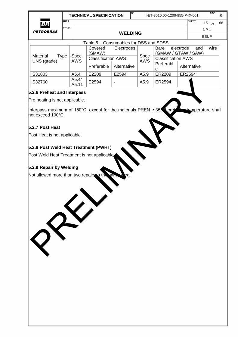
Table 5 – Consumables for DSS and SDSS
Material Type UNS (grade)
Spec. AWS
Covered Electrodes (SMAW)
Spec AWS
Bare electrode and wire (GMAW / GTAW / SAW)
Classification AWS Classification AWS
Preferable Alternative Preferable
Alternative
S31803 A5.4 E2209 E2594 A5.9 ER2209 ER2594
S32760 A5.4/ A5.11
E2594 - A5.9 ER2594
5.2.6 Preheat and Interpass
Pre heating is not applicable.
Interpass maximum of 150°C, except for the materials PREN ≥ 35 wherein the temperature shall not exceed 100°C.
5.2.7 Post Heat
Post Heat is not applicable.
5.2.8 Post Weld Heat Treatment (PWHT)
Post Weld Heat Treatment is not applicable.
5.2.9 Repair by Welding
Not allowed more than two repairs in the same area.
PRELIMIN
ARY
TECHNICAL SPECIFICATION Nº:
I-ET-3010.00-1200-955-P4X-001 REV.
0
AREA: SHEET 16 of 68
TITLE:
WELDING NP-1
ESUP
5.3 WELDING OF NICKEL ALLOY STEEL
5.3.1 Scope
This item establishes the requirements for welding nickel alloy steels (C-Ni steels) with nickel content up to 9%, which are usually employed for cryogenic applications (temperatures below -46ºC).
The metallurgical aspects of welding the nickel cryogenic steels are primarily concerned with the avoidance of cracking in the welded joint and with the maintenance of acceptable properties in the weld metal and HAZ. In the past, hot cracking of nickel containing weld metals was a recurring problem; now it is well understood that restriction of impurities, such as sulfur and phosphorous, to low levels (<0.01%) is essential to sound welds. Since the nickel steels have enough carbon and hardenability to be susceptible to hydrogen-induced cracking, they must be welded with low-hydrogen-potential processes. Preheating to 200-300°F (100-150°C) is helpful in avoiding hydrogen or restraint cracking.
In the 9% Ni steels, the HAZ will become essentially martensitic, tempered in some parts by the multiple passes. At the low carbon level characteristic of these steels, the martensite retains a high degree of toughness and post weld heat treatment is usually not necessary.
It is important to note that steels with nickel content in excess of 1% when in sour service shall always be qualified by a Sulphide Stress Corrosion test in accordance with ISO 15156-1. This test is then applicable for the base materials and for the welding procedures.
5.3.2 Weldability
They have good weldability; however, the larger the addition of nickel the higher the hardenability of steel, particularly in steels with high nickel content (Ni ≥ 5 %) in which the HAZ consists of martensite with relative toughness as a function of nickel content and control of carbon content.
Mechanical properties and toughness may be compromised when there is overgrowth of grains of HAZ due to high heat input adopted.
In homogeneous and, specially, heterogeneous welding, the weld pool of C-Ni steels presents low fluidity when compared to C-Mn steel.
Contaminants of foreign origin shall not contact these materials, especially the sulfur from thermal pencil, grease, soap, and so on. C-Ni steels are classified as P number 9 and 11A, according to ASME BPVC Section IX.
Porosity may be avoided by controlling the diffusible hydrogen and by using a very short arc. [Recommended Practice]
Due to the metallurgical properties, this material presents higher capacity of magnetization, compared to carbon steel. Extra care shall be taken during the weld procedures, especially in the root welding. Demagnetization or cancellation of the magnetic field in some cases may be required before welding to prevent magnetic arc blow, especially in small diameter tubes and connections.
5.3.3 General Welding Technique
The welding shall be of multiple passes, with straight and slightly convex passes. Passes that have excessive convexity shall be repaired by grinding to avoid lack of fusion. In fillet welds (like socket welds) the finishing passes shall be concave.
PRELIMIN
ARY
TECHNICAL SPECIFICATION Nº:
I-ET-3010.00-1200-955-P4X-001 REV.
0
AREA: SHEET 17 of 68
TITLE:
WELDING NP-1
ESUP
The heat input shall be below 2 kJ/mm in homogeneous and 1,5 kJ/mm in heterogeneous welding. With the submerged arc welding process, it shall be lower than 2,8 kJ/mm and 2,5 kJ/mm, respectively, except that for 9% Nickel heat input shall always be limited to 2,0 kJ/mm.
In the qualifying phase of heterogeneous welds, it is recommended longitudinal bending test
instead of the transverse bending. [Recommended Practice]
The manual heating by oxy-gas flame (shower-type blowtorch) shall be limited to pieces with thickness below 13 mm and a nominal diameter of up to 10 inches.
5.3.4 Applicable Welding Processes
The SMAW, GTAW, GMAW, FCAW-G and SAW processes are permitted. Other processes may be applied upon previous approval of PETROBRAS.
SMAW
a) the coating shall be basic and have a maximum diffusible hydrogen of H8;
b) root welding by SMAW process is not permitted;
c) the oscillation of the electrode shall be such that the pass width does not exceed three times
the coated electrode core diameter.
d) the use of synthetic consumables is not permitted;
GTAW
a) the shielding gas of the purge shall be argon, helium or a mixture of these gases. Purge with
nitrogen is not allowed;
b) the purge of the root shall be maintained until the 2nd weld layer or 6,4 mm, whichever is
thicker;
c) only this welding process is allowed for the root passes (roots pass and root reinforcement) up
to 6,4 mm.
GMAW
a) additional care shall be taken for overhead position using solid wires due low wettability of the
filler metal NiCrMo-3.
b) root welding and root reinforcing passes by GMAW process are not permitted. It is not
permitted to weld branch connections, pipe connections with hull (nozzles) and socket welds.
SAW
a) the flux shall be neutral or basic, it is not permitted the presence of alloying elements, and it
shall contain a level H8 for maximum diffusible hydrogen;
b) special care shall be given to the flux regarding the contamination risk by dirt and moisture.
FCAW
a) The FCAW-G process is permitted;
b) The FCAW-S process (self-shielded, flux-cored) is not permitted;
PRELIMIN
ARY
TECHNICAL SPECIFICATION Nº:
I-ET-3010.00-1200-955-P4X-001 REV.
0
AREA: SHEET 18 of 68
TITLE:
WELDING NP-1
ESUP
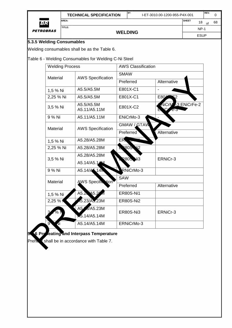
5.3.5 Welding Consumables
Welding consumables shall be as the Table 6.
Table 6 - Welding Consumables for Welding C-Ni Steel
Welding Process AWS Classification
Material AWS Specification SMAW
Preferred Alternative
1,5 % Ni A5.5/A5.5M E801X-C1 -
2,25 % Ni A5.5/A5.5M E801X-C1 E801X-C2
3,5 % Ni A5.5/A5.5M A5.11/A5.11M
E801X-C2 ENiCrMo-3 ENiCrFe-2 ENiCrFe-3
9 % Ni A5.11/A5.11M ENiCrMo-3 -
Material AWS Specification GMAW / GTAW
Preferred Alternative
1,5 % Ni A5.28/A5.28M ER80S-Ni1
2,25 % Ni A5.28/A5.28M ER80S-Ni2
3,5 % Ni A5.28/A5.28M
A5.14/A5.14M ER80S-Ni3 ERNiCr-3
9 % Ni A5.14/A5.14M ERNiCrMo-3
Material AWS Specification SAW
Preferred Alternative
1,5 % Ni A5.23/A5.23M ER80S-Ni1
2,25 % Ni A5.23/A5.23M ER80S-Ni2
3,5 % Ni A5.23/A5.23M
A5.14/A5.14M ER80S-Ni3 ERNiCr-3
9 % Ni A5.14/A5.14M ERNiCrMo-3
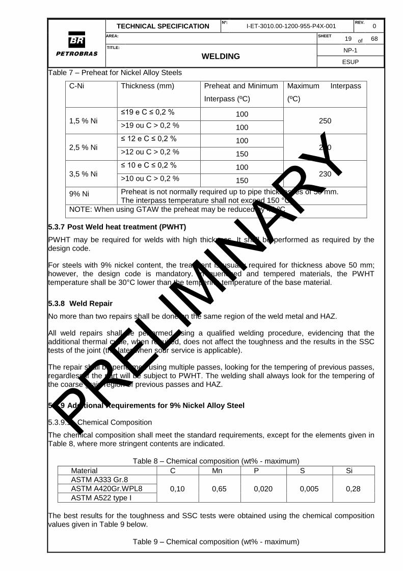
5.3.6 Preheating and Interpass Temperature
Preheat shall be in accordance with Table 7. PRELIMIN
ARY
TECHNICAL SPECIFICATION Nº:
I-ET-3010.00-1200-955-P4X-001 REV.
0
AREA: SHEET 19 of 68
TITLE:
WELDING NP-1
ESUP
Table 7 – Preheat for Nickel Alloy Steels
C-Ni Thickness (mm) Preheat and Minimum
Interpass (ºC)
Maximum Interpass
(ºC)
1,5 % Ni
≤19 e C ≤ 0,2 % 100 250
>19 ou C > 0,2 % 100
2,5 % Ni
≤ 12 e C ≤ 0,2 % 100 250
>12 ou C > 0,2 % 150
3,5 % Ni ≤ 10 e C ≤ 0,2 % 100
230 >10 ou C > 0,2 % 150
9% Ni Preheat is not normally required up to pipe thicknesses of 50 mm. The interpass temperature shall not exceed 150 °C.
NOTE: When using GTAW the preheat may be reduced by 40 ºC
5.3.7 Post Weld heat treatment (PWHT)
PWHT may be required for welds with high thickness. It shall be performed as required by the design code.
For steels with 9% nickel content, the treatment is usually required for thickness above 50 mm; however, the design code is mandatory. In quenched and tempered materials, the PWHT temperature shall be 30°C lower than the tempering temperature of the base material.
5.3.8 Weld Repair
No more than two repairs shall be done on the same region of the weld metal and HAZ.
All weld repairs shall be performed using a qualified welding procedure, evidencing that the additional thermal cycle, when required, does not affect the toughness and the results in the SSC tests of the joint (the later when sour service is applicable).
The repair shall be performed using multiple passes, looking for the tempering of previous passes, regardless if the part will be subject to PWHT. The welding shall always look for the tempering of the coarse grain region of previous passes and HAZ.
5.3.9 Additional Requirements for 9% Nickel Alloy Steel
5.3.9.1 Chemical Composition
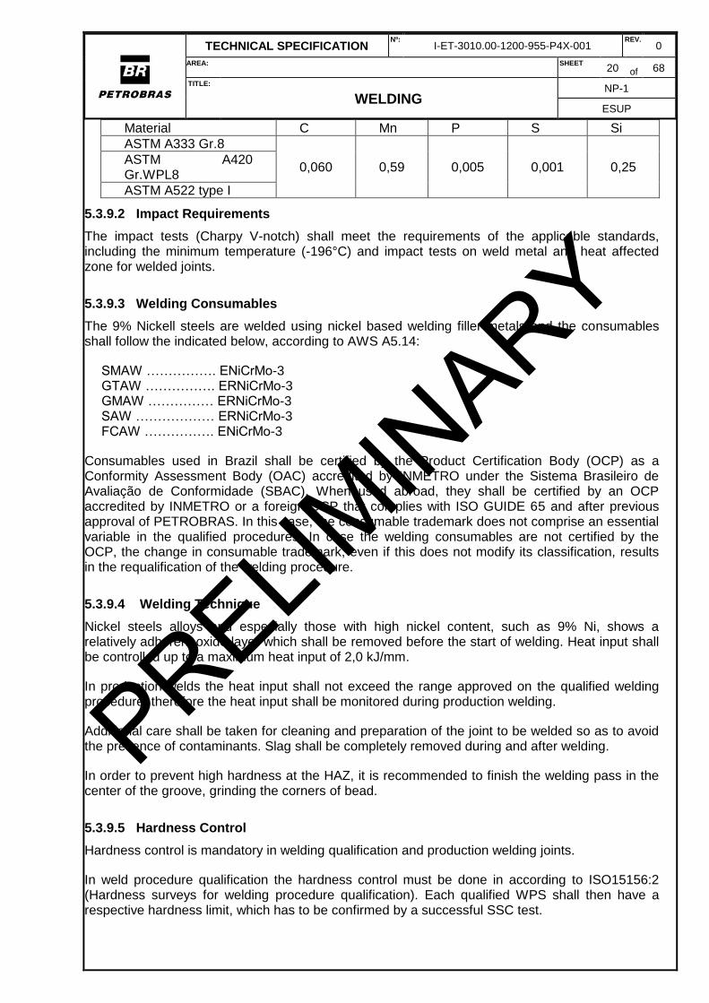
The chemical composition shall meet the standard requirements, except for the elements given in Table 8, where more stringent contents are indicated.
Table 8 – Chemical composition (wt% - maximum)
Material C Mn P S Si
ASTM A333 Gr.8
0,10 0,65 0,020 0,005 0,28 ASTM A420Gr.WPL8
ASTM A522 type I
The best results for the toughness and SSC tests were obtained using the chemical composition values given in Table 9 below.
Table 9 – Chemical composition (wt% - maximum)
PRELIMIN
ARY
TECHNICAL SPECIFICATION Nº:
I-ET-3010.00-1200-955-P4X-001 REV.
0
AREA: SHEET 20 of 68
TITLE:
WELDING NP-1
ESUP
Material C Mn P S Si
ASTM A333 Gr.8
0,060 0,59 0,005 0,001 0,25 ASTM A420 Gr.WPL8
ASTM A522 type I
5.3.9.2 Impact Requirements
The impact tests (Charpy V-notch) shall meet the requirements of the applicable standards, including the minimum temperature (-196°C) and impact tests on weld metal and heat affected zone for welded joints.
5.3.9.3 Welding Consumables
The 9% Nickell steels are welded using nickel based welding filler metals and the consumables shall follow the indicated below, according to AWS A5.14:
SMAW ……………. ENiCrMo-3 GTAW ……………. ERNiCrMo-3 GMAW …………… ERNiCrMo-3 SAW ……………… ERNiCrMo-3 FCAW ……………. ENiCrMo-3
Consumables used in Brazil shall be certified by the Product Certification Body (OCP) as a Conformity Assessment Body (OAC) accredited by INMETRO under the Sistema Brasileiro de Avaliação de Conformidade (SBAC). When used abroad, they shall be certified by an OCP accredited by INMETRO or a foreign OCP that complies with ISO GUIDE 65 and after previous approval of PETROBRAS. In this case, the consumable trademark does not comprise an essential variable in the qualified procedures. In case the welding consumables are not certified by the OCP, the change in consumable trademark, even if this does not modify its classification, results in the requalification of the welding procedure.
5.3.9.4 Welding Technique
Nickel steels alloys and especially those with high nickel content, such as 9% Ni, shows a relatively adherent oxide layer which shall be removed before the start of welding. Heat input shall be controlled up to a maximum heat input of 2,0 kJ/mm.
In production welds the heat input shall not exceed the range approved on the qualified welding procedure, therefore the heat input shall be monitored during production welding.
Additional care shall be taken for cleaning and preparation of the joint to be welded so as to avoid the presence of contaminants. Slag shall be completely removed during and after welding.
In order to prevent high hardness at the HAZ, it is recommended to finish the welding pass in the center of the groove, grinding the corners of bead.
5.3.9.5 Hardness Control
Hardness control is mandatory in welding qualification and production welding joints.
In weld procedure qualification the hardness control must be done in according to ISO15156:2 (Hardness surveys for welding procedure qualification). Each qualified WPS shall then have a respective hardness limit, which has to be confirmed by a successful SSC test.
PRELIMIN
ARY
TECHNICAL SPECIFICATION Nº:
I-ET-3010.00-1200-955-P4X-001 REV.
0
AREA: SHEET 21 of 68
TITLE:
WELDING NP-1
ESUP
In production welding joints, the hardness control shall be done using portable instruments according to the UCI method (Ultrasonic Contact Impedance standardized according to ASTM A 1038 and DIN 50159).
When the root of the production welding is inaccessible, the hardness limit shall be measured externally in HAZ and set as the maximum hardness found on the same region of qualified welding joint plus 5%.
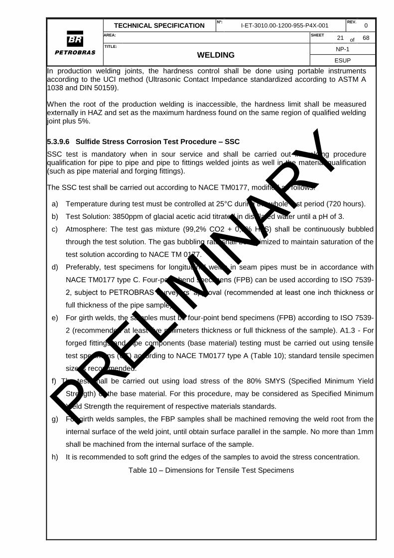
5.3.9.6 Sulfide Stress Corrosion Test Procedure – SSC
SSC test is mandatory when in sour service and shall be carried out in welding procedure qualification for pipe to pipe and pipe to fittings welded joints as well in the material qualification (such as pipe material and forging fittings).
The SSC test shall be carried out according to NACE TM0177, modified as follows:
a) Temperature during test must be controlled at 25°C during the whole test period (720 hours).
b) Test Solution: 3850ppm of glacial acetic acid titrated in distillated water until a pH of 3.
c) Atmosphere: The test gas mixture (99,2% CO2 + 0,8% H2S) shall be continuously bubbled
through the test solution. The gas bubbling rate shall be optimized to maintain saturation of the
test solution according to NACE TM 0177.
d) Preferably, test specimens for longitudinal welds in seam pipes must be in accordance with
NACE TM0177 type C. Four-point bend specimens (FPB) can be used according to ISO 7539-
2, subject to PETROBRAS Surveyors’ approval (recommended at least one inch thickness or
full thickness of the pipe sample).
e) For girth welds, the samples must be four-point bend specimens (FPB) according to ISO 7539-
2 (recommended at least five millimeters thickness or full thickness of the sample). A1.3 - For
forged fittings and pipe components (base material) testing must be carried out using tensile
test specimens (UT) according to NACE TM0177 type A (Table 10); standard tensile specimen
size is recommended.
f) The test shall be carried out using load stress of the 80% SMYS (Specified Minimum Yield
Strength) of the base material. For this procedure, may be considered as Specified Minimum
Yield Strength the requirement of respective materials standards.
g) For girth welds samples, the FBP samples shall be machined removing the weld root from the
internal surface of the weld joint, until obtain surface parallel in the sample. No more than 1mm
shall be machined from the internal surface of the sample.
h) It is recommended to soft grind the edges of the samples to avoid the stress concentration.
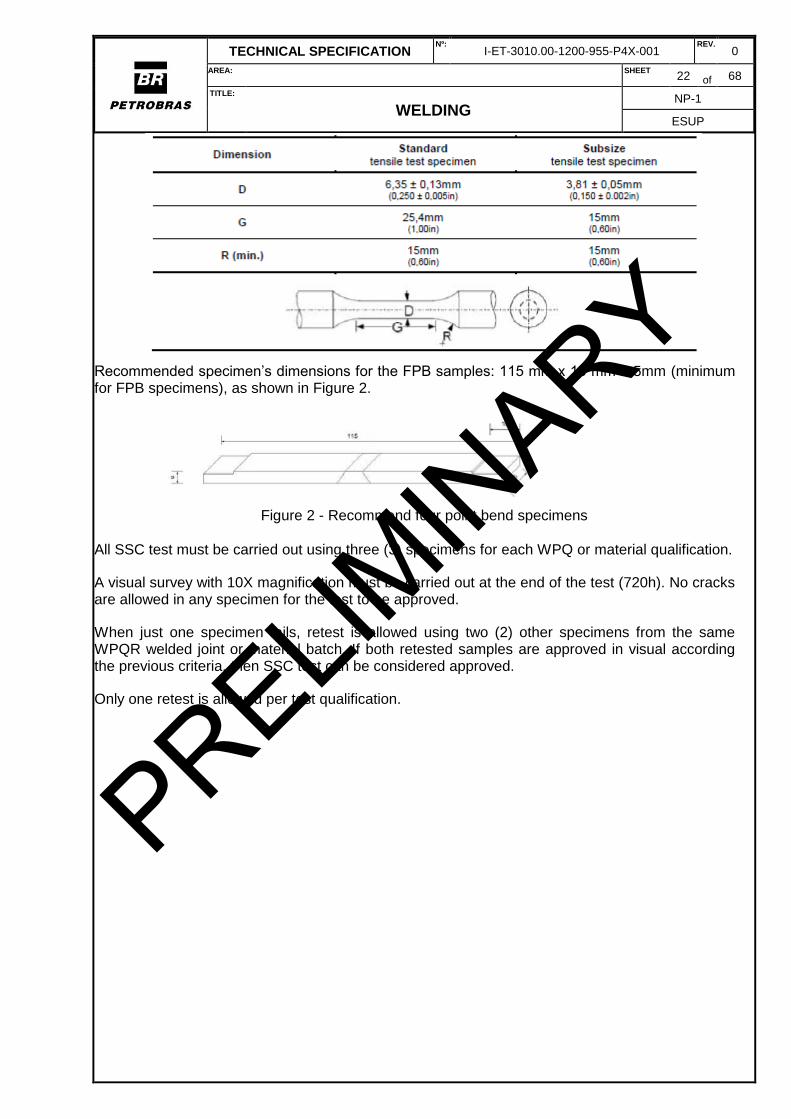
Table 10 – Dimensions for Tensile Test Specimens
PRELIMIN
ARY
TECHNICAL SPECIFICATION Nº:
I-ET-3010.00-1200-955-P4X-001 REV.
0
AREA: SHEET 22 of 68
TITLE:
WELDING NP-1
ESUP
Recommended specimen’s dimensions for the FPB samples: 115 mm x 15 mm x 5mm (minimum for FPB specimens), as shown in Figure 2.
Figure 2 - Recommend four point bend specimens
All SSC test must be carried out using three (3) specimens for each WPQ or material qualification.
A visual survey with 10X magnification must be carried out at the end of the test (720h). No cracks are allowed in any specimen for the test to be approved.
When just one specimen fails, retest is allowed using two (2) other specimens from the same WPQR welded joint or material batch. If both retested samples are approved in visual according the previous criteria, then SSC test can be considered approved.
Only one retest is allowed per test qualification.
PRELIMIN
ARY
TECHNICAL SPECIFICATION Nº:
I-ET-3010.00-1200-955-P4X-001 REV.
0
AREA: SHEET 23 of 68
TITLE:
WELDING NP-1
ESUP
5.4 COPPER AND COPPER ALLOYS
5.4.1 Introduction
Copper and its alloys are generally used due to their high mechanical strength (especially fatigue) and corrosion resistance, in addition to the excellent thermal and/or electric conductivity.
Several alloys are produced by adding the main following elements: aluminum, nickel, tin, and zinc. Phosphorus and silicon are used as deoxidizers. For purposes of this technical specification, besides the commercially pure copper (99,3% Cu), the Copper-Nickel (Cu-Ni with up to 30%Ni) and Copper-Aluminum (Bronze-Aluminum up to 8%AL) alloys are considered, with the following specifications:
— C-10200 deoxidized commercially pure copper (Cu);
— C-70600 alloy 90Cu-10Ni (Cu-Ni-Fe);
— C-71500 alloy 70Cu-30Ni (Cu-Ni-Fe);
— C-61400 bronze-aluminum alloy (Al-Cu-Fe).
The cited materials show solid solution hardening capabilities, homogeneous microstructure with single phase CFC-α, including the C-61400 bronze-aluminum, in which the percentage of aluminum does not exceed 8%.
5.4.2 Weldability
In general, they have rapid cooling rate, favoring the lack of fusion due to the high coefficient of thermal conductivity of copper.
The weld pool of commercially pure copper has great fluidity.
Copper alloys when enriched in solute atoms become susceptible to hot cracking, which may be avoided by reduction of root opening, enhanced deposition, and by preheating in some alloys.
The mechanical properties may be compromised by the quick formation of copper oxide. This oxide is hygroscopic and highly reactive when exposed to oxygen at high temperature. The mechanical strength is compromised by the formation of pores (oxides) and impurities (antimony, arsenic, bismuth, and lead).
5.4.3 General Welding Technique
Hygroscopic oxide removal, slag removal, cleaning and cutting tools shall be used exclusively for these materials, and meet the following requirements:
a) Slag removal and cleaning tools shall be made of copper alloy, stainless steel or be coated
with this material, and only be used for welding of copper and its alloys;
b) The cutting disks shall have nylon core or fiberglass;
c) Additional care shall be taken as cleaning and preparation of the joint to be welded, in order to
prevent the existence of contaminants.
The surface of the parts shall be protected against spatter adhesion and other projections resulting from welding.
In a range of 200 mm centered on the joint, by its internal and external sides, the joint shall be cleaned with solvent, and there shall not be any contamination with substances containing sulfur,
PRELIMIN
ARY
TECHNICAL SPECIFICATION Nº:
I-ET-3010.00-1200-955-P4X-001 REV.
0
AREA: SHEET 24 of 68
TITLE:
WELDING NP-1
ESUP
lead, zinc, and their compounds. Thermal pencil and industrial marker shall not be used due to the risk of contamination. The welded joints shall not be contaminated by residues of any kind resulting from the welding and assembly work.
Slag shall be completely removed during and after welding. The surface irregularities of the weld shall be removed by grinding, for each deposited layer.
The welding by GTAW and GMAW processes shall be performed with purging gas to protect the weld zone and HAZ. The measurement by oxymeter shall indicate oxygen content of 100 ppm or lower before the start of welding.
5.4.4 Applicable Welding Processes
The GTAW, PAW, GMAW, and SMAW welding processes are permitted.
SMAW
a) AWS A5.6 consumables shall not be used in equipment operating under pressure. They can be
used in low responsibility joints;
b) higher densities of currents are normally used when compared to welding of carbon steel, and
usually limited to a flat position;
c) weaving pass is not permitted due to a higher incidence of pores;
d) consumables shall be similar to those shown in Table 21 for GTAW and GMAW processes.
GTAW
a) consumables are used in thicknesses above 3 mm. Below 3 mm, the welding is usually performed
without filler material (autogenous);
b) In welding of deoxidized copper in butt joints, it may necessary to use backing due to the high
fluidity of copper.
c) shielding gases shall be: helium, argon or helium + argon mixture. The use of the argon results in
low penetration, which may be partially compensated by increasing the preheating temperature.
GMAW
a) the process is more sensitive to pore formation than GTAW;
b) argon and inert gas mixtures are used;
c) in welding of deoxidized copper in butt joints, it may necessary to use backing due to the high
fluidity of copper.
d) the butt welding is basically performed in a flat position with spray transfer mode. Out of position,
the welding may be performed in lower fluidity alloys (Cu-Ni and bronze aluminum) and using small
diameter wires.
5.4.5 General Conditions for Consumables
The consumables shall follow the instructions in Table 11.
TABLE 11 - Rods for Copper and Copper Alloys
Material - Alloy AWS Specification AWS Classification
PRELIMIN
ARY
TECHNICAL SPECIFICATION Nº:
I-ET-3010.00-1200-955-P4X-001 REV.
0
AREA: SHEET 25 of 68
TITLE:
WELDING NP-1
ESUP
C-10200 (commercially pure Cu)
A5.7/A5.7M ERCu
C-70600 alloy (90Cu-10Ni) A5.7/A5.7M ERCuNi
C-71500 alloy (70Cu-30N) A5.7/A5.7M ERCuNi
C-61400 alloy (Al-Cu-Fe) A5.7/A5.7M ERCuAL-A2
5.4.6 Preheating and Interpass Temperatures
Pure deoxidized copper with thickness below 3 mm does not require preheating.
Pure deoxidized copper with thickness between 3 mm and 6 mm shall be preheated at 100 ºC.
Pure deoxidized copper with thickness between 6 mm and 10 mm shall be preheated at 220 ºC.
Pure copper with a thickness above 10 mm shall be preheated from 260 ºC to 480 ºC.
Bronze-aluminum with a thickness of 6 mm or below does not require preheating.
Bronze-aluminum with thickness above 6 mm and Aluminum below 10% - preheating and interpass shall not exceed 150 ºC.
Copper-nickel alloys: is not necessary to preheat, and interpass shall not exceed 65 ºC.
5.4.7 Post-Heating
It is not required.
5.4.8 Post Weld heat treatment (PWHT)
It is not required.
PRELIMIN
ARY
TECHNICAL SPECIFICATION Nº:
I-ET-3010.00-1200-955-P4X-001 REV.
0
AREA: SHEET 26 of 68
TITLE:
WELDING NP-1
ESUP
5.5 INCONEL
5.5.1 General Welding Technique
The cut shall be made by plasma, laser, water jet cutting or appropriate cutting disk, not being permitted to cut with graphite electrode and oxy-cutting. In case of thermal cutting, the HAZ shall be removed by machining or grinding.
The welding shall be performed with low heat input. The input to processes with high density of current shall not exceed 1,8 kJ/mm. For GTAW and SMAW processes, it shall be lower than 1,5 kJ/mm.
Basic problems of welding nickel alloys may be avoided by cleaning the bevels and rods with non-chlorinated solvents, protecting them against wind and moisture, using specific tooling support for nickel alloys, and having functional hygiene with the use of gloves and apron at work.
Lack of penetration or fusion is controlled by the slight increase in bevel angle, reduction in nose height, and increase in root opening. The previous training of welders, cleaning, and removal of adhering oxide layer are essential.
The welding of nickel allows shall be performed with straight passes. To reduce the risk of solidification cracking, some details of extreme importance shall not be overlooked, such as: joint preparation, superficial cleaning, quantity of material deposited per pass in the width/depth ratio equal to one, slight convexity of passes, and suitable welding speed in order to avoid weld pool in drop form.
The risk of crater-type cracks may be mitigated by training welders in the torch outlet. The profile shall be slightly convex.
Imperfections such as dents, bites, arc openings and spatters shall be carefully removed. Slag removal, cleaning and cutting tools shall be compatible with nickel alloys and used only for these materials, not having iron compounds and sulfur (for example, iron sulfide).
The part of the auxiliary device of assembly touching or welded into the equipment shall have the same P number of the base metal, according to the classification of ASME BPVC Section IX, or otherwise be coated with the consumable specified for the welding of base metal in deposits of at least two layers. Contamination with carbon (carburizing followed by precipitation), iron and iron oxide are detrimental to corrosion resistance. The use of wedges, and copper and steel hammers or lead pads is not permitted. Contact with industrial scaffold causes exposure to zinc.
In cases of contamination, the surface shall be cleaned by grinding or pickled by controlled etching, and then passivated. Etching and passivation shall comply with ASTM A 380.
Contamination by contact with sulfur, zinc, copper, tin and lead irreversibly compromise the nickel alloys when exposed to high temperature. The use of temperature indicators based on polymer fusion and industrial markers with these contaminants is not permitted. Cutting oil shall be free of sulfur.
After the welding completion and before the start of operation, soaps and detergents used in bubble and liquid penetrant tests shall be removed, since they may contain elements with low melting point, especially sulfur. Slag and flux residues shall be removed after welding, because they compromise the corrosion resistance in operation (fluoride). Contact with chlorine or fluoride is extremely harmful, causing stress or pitting corrosion.
Welding shall be performed with oxygen-free shielding gas at the root of weld (less than 100 ppm of oxygen) in order to protect the weld zone and HAZ. This protection shall be maintained until the
PRELIMIN
ARY
TECHNICAL SPECIFICATION Nº:
I-ET-3010.00-1200-955-P4X-001 REV.
0
AREA: SHEET 27 of 68
TITLE:
WELDING NP-1
ESUP
completion of the third weld layer or 6.3 mm, ensuring the absence of oxygen. This internal protection is applicable for butt welds, socket welds, sealing welds as well as for any weld performed on the opposite side when thickness of the base material is below 6.3 mm (for example, the welding of an external support in a piping requires internal gas protection). Argon and helium may be used as purge gas. Nitrogen shall only be permitted after previous evaluation and approval of PETROBRAS. The measurement of residual oxygen shall be performed using an oxymeter with threshold value of 50 ppm.
5.5.2 Applicable Welding Processes
The SMAW, GTAW, SAW, GMAW, and FCAW-G welding processes are permitted, the last two with restrictions. The FCAW-S process is not permitted.
SMAW
a) the use of synthetic consumables is not permitted;
b) root welding and second layer by SMAW process is not permitted;
c) when the welding of nickel allows is performed using the SMAW processes, it is important that the
slag is completely removed before the joint gets into operation.
GTAW
a) consumables shall be constantly cleaned with acetone before the opening the arc;
b) besides argon (99,99%), the argon + helium mixture or only helium may be used as shielding gas.
The argon + H2
mixture (1 % H2 to 3 % H2maximum) may only be used with previous approval of PETROBRAS;
c) It is recommended to use tungsten electrodes with addition of Cerium or Lanthanum.
[Recommended Practice]
GMAW
a) root and root stiffener pass weldin g by GMAW process are not permitted;
b) the use of this process in equipment, ducts or pipelines subject to pressure shall have previous
approval of PETROBRAS;
c) welding with pure CO2 shielding gas is not permitted;
d) the shielding gas in GMAW process shall consist of pure argon, argon + O2 (2 % maximum),
argon + CO2 (2 % maximum), argon + H2 (1 % maximum);
e) The limitations of using this process are due to increased susceptibility to lack of fusion, low
wettability and fluidity of nickel alloys.
FCAW
a) the use of this process in equipment, ducts or pipelines subject to pressure is not permitted;
b) root and root stiffener pass welding by FCAW process are not permitted;
c) coat welding by FCAW process with shielding gas is only permitted with prior approval of
PETROBRAS;
d) welding with pure CO2 shielding gas is not permitted;
PRELIMIN
ARY
TECHNICAL SPECIFICATION Nº:
I-ET-3010.00-1200-955-P4X-001 REV.
0
AREA: SHEET 28 of 68
TITLE:
WELDING NP-1
ESUP
e) the shielding gas in FCAW process shall be Argon + 25 % CO2 or Argon + 20 % CO2.
SAW
a) the flux shall be neutral or basic, and linked fluxes are not permitted;
b) when the welding of nickel alloys is performed using the SAW processes, it is important that the
slag and flux residues are completely removed before exposure of the joint in operation.
5.5.3 General Conditions for Consumables
The consumables shall follow the instructions in Table 12.
TABLE 12- Electrodes, Rods and solid wires for nickel and nickel alloys
The consumables for coat welding by the FCAW-G cored wire processes shall comply with AWS A5.34. AWS classification TNiXXXXT1 or TNiXXXXT0-4-4.
5.5.4 Preheating and Interpass
Preheating is not required.
The interpass temperature shall be below 150 °C.
5.5.5 Post-Heating
It is not required.
5.5.6 Post Weld heat treatment (PWHT)
It is usually not performed; however, it may be required depending on the fluid and according to design specification.
5.5.7 Weld Repair
The defect shall be removed by manual or mechanized grinding, milling or machining.
After removing the defect, the region shall be examined with liquid penetrant. The welding shall be performed with low heat input using the GTAW process.
Only one repair in the same area is permitted.
PRELIMIN
ARY
TECHNICAL SPECIFICATION Nº:
I-ET-3010.00-1200-955-P4X-001 REV.
0
AREA: SHEET 29 of 68
TITLE:
WELDING NP-1
ESUP
5.6 AUSTENITIC STAINLESS STEELS
5.6.1 Introduction
This Section includes the austenitic stainless steels with microstructure fully austenitic or austenitic-ferritic, such as:
- steels from AISI 3XX series (304, 316, 317, 321, 347, 310) standard or conventional;
- low carbon steels from AISI 3XXL series, used in corrosive services with carbon contente lower
than 0,04 %;
- controlled carbon steels from AISI 3XXH series, used in services at high temperature, with carbon
contents ranging from 0,04 % to 0,1 %;
- cast steels for general use and for use at high temperatures.
5.6.2 General Welding Technique
The fabrication of stainless steel piping and equipment shall be made in a segregated and protected area, preferably in a shed separated from other materials.
Hot cutting with graphite electrode or oxycutting is not permitted. Hot cutting shall be preferably performed by plasma or laser, and the surface shall be ground in order to remove any signs of oxidation and irregularities.
The root opening shall be slightly wider than the one commonly used for carbon steels, because the root tends to close more often, which may result in lack of fusion. Austenitic stainless steels have thermal expansion coefficient approximately 50% greater than the carbon steel, and lower thermal conductivity. These factors generate high residual stress and higher tendency to distortion (warping) in the welded joint.
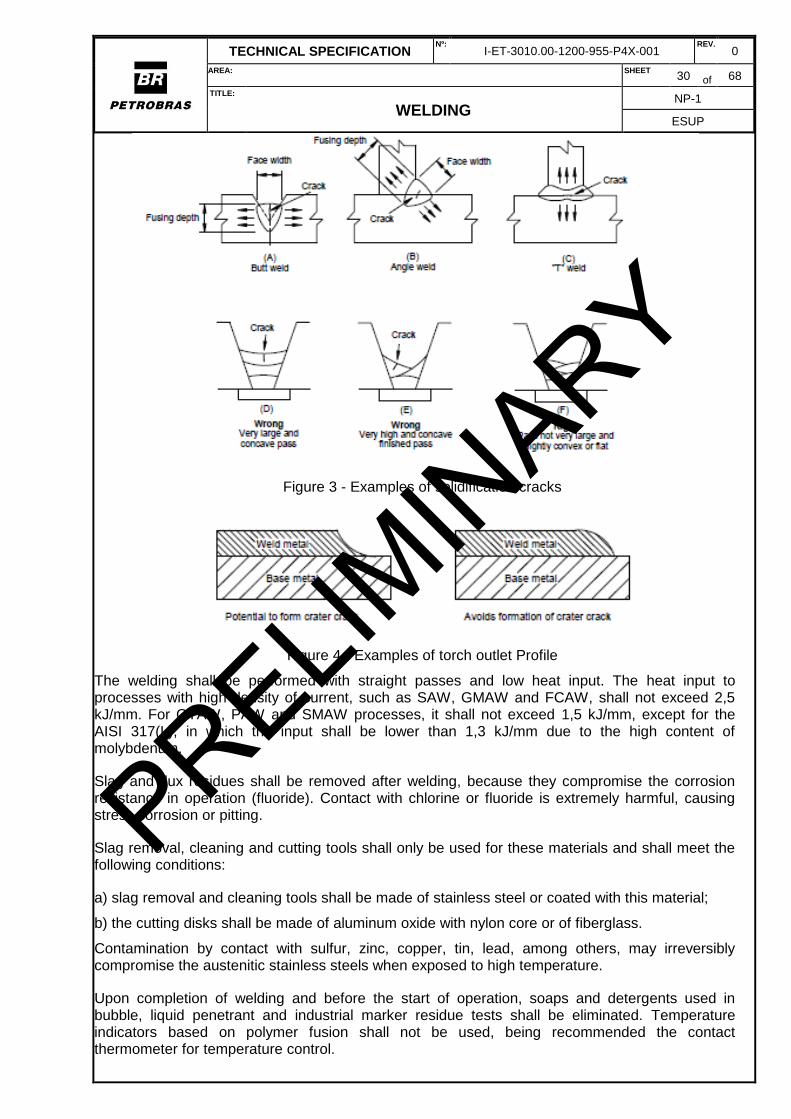
In welding of austenitic stainless steel, some details of extreme importance shall not be overlooked in order to reduce the risk of solidification cracking, such as: joint preparation, surface cleaning, quantity of material deposited per pass, aiming the width/depth ratio equal to one, slight convexity of passes, and suitable welding speed in order to avoid weld pool in drop form. Figure 3 illustrates the formation of cracks due to the width/depth ratio (A) (B) (C) and concavity (D).
The risk of crater-type hot cracks may be mitigated by training welders on torch outlet. The profile shall be slightly convex, as shown in Figure 4.
It is recommended that the surface of the parts is protected from adherence from spatter and other projections resulting from the weld, especially when the GMAW and FCAW processes are used. [Recommended Practice]
The part of the auxiliary assembly device touching or welded in the equipment shall have the same P number of the base metal, according to the classification of ASME BPVC Section IX, or otherwise be coated with the consumable specified for welding of base metal in deposits of at least two layers. Contamination with carbon (carburizing followed by precipitation), iron and iron oxide are detrimental to corrosion resistance.
PRELIMIN
ARY
TECHNICAL SPECIFICATION Nº:
I-ET-3010.00-1200-955-P4X-001 REV.
0
AREA: SHEET 30 of 68
TITLE:
WELDING NP-1
ESUP
Figure 3 - Examples of solidification cracks
Figure 4 - Examples of torch outlet Profile
The welding shall be performed with straight passes and low heat input. The heat input to processes with high density of current, such as SAW, GMAW and FCAW, shall not exceed 2,5 kJ/mm. For GTAW, PAW and SMAW processes, it shall not exceed 1,5 kJ/mm, except for the AISI 317(L), in which the input shall be lower than 1,3 kJ/mm due to the high content of molybdenum.
Slag and flux residues shall be removed after welding, because they compromise the corrosion resistance in operation (fluoride). Contact with chlorine or fluoride is extremely harmful, causing stress corrosion or pitting.
Slag removal, cleaning and cutting tools shall only be used for these materials and shall meet the following conditions:
a) slag removal and cleaning tools shall be made of stainless steel or coated with this material;
b) the cutting disks shall be made of aluminum oxide with nylon core or of fiberglass.
Contamination by contact with sulfur, zinc, copper, tin, lead, among others, may irreversibly compromise the austenitic stainless steels when exposed to high temperature.
Upon completion of welding and before the start of operation, soaps and detergents used in bubble, liquid penetrant and industrial marker residue tests shall be eliminated. Temperature indicators based on polymer fusion shall not be used, being recommended the contact thermometer for temperature control.
PRELIMIN
ARY
TECHNICAL SPECIFICATION Nº:
I-ET-3010.00-1200-955-P4X-001 REV.
0
AREA: SHEET 31 of 68
TITLE:
WELDING NP-1
ESUP
Welding shall be performed with oxygen-free shielding gas at the root of weld (less than 100 ppm of oxygen) in order to protect the weld zone and HAZ. This protection shall be maintained until the completion of the third weld layer or 6.3 mm, ensuring the absence of oxygen. This internal protection is applicable for butt welds, socket welds, sealing welds as well as for any weld performed on the opposite side when thickness of the base material is below 6.3 mm (for example, the welding of an external support in a piping requires internal gas protection). Argon and helium may be used as purge gas. The effectiveness of root purging can be later identified by visual assessment.
Purging with nitrogen during welding is only permitted after previous review and evaluation of PETROBRAS. The ferrite content in base material, gas purity, and risk of hot cracking after welding shall be evaluated.
The authorization for joint welding without internal access shall be made after checking and evidencing the oxygen content inside the tube. This measurement of residual oxygen shall be performed using an oxymeter with threshold value of 100 ppm or mL/m³. The device shall be able to detect the presence of oxygen from 0 to 1 000 ppm or mL/m3.
The contaminated base metal and face and root regions with coloring 4 or above shall be treated after welding, therefore, extra care is essential to the purge. In general cases, the passivated layer may be restored by removing the oxidized layer formed at high temperature, either by controlled etching, sanding or blasting with glass beads, the latter indicated for large surfaces. Cleaning with acid requires special care about the contamination of the environment and the health of the applicator. In applications requiring corrosion resistance, passivation is indicated immediately after sanding or etching. Pickling and passivation shall comply with ASTM A 380.
5.6.3 Applicable Welding Processes
The SMAW, GMAW-P, GMAW, FCAW-G, GTAW, SAW, and PAW processes are permitted. The FCAW-S process is not permitted.
SMAW
a) the use of synthetic consumables is not permitted;
b) the welding of AISI 321 steel shall be performed with consumable 347 due to the low transfer of
titanium in the process;
c) whenever the material is exposed to temperature above 480 ºC in the operation, the consumable
shall be acquired according to AWS A5.01, Schedule J, ensuring its bismuth content does not
exceed 0,002 %.
GTAW
a) besides argon (99,99 %), the argon + helium mixture or only helium may be used as shielding
gas. the argon + H2 mixture (1 % H2 to 3 % H2 maximum) may only be used with previous approval
of PETROBRAS;
b) root purging with inert gas is required during welding in order to prevent internal oxidation on the
root face and HAZ;
c) when a cored wire specific for GTAW welding (100 % argon) is used, any flux residue shall be
removed, especially where there is contact with the fluid. The welding may be performed with inert
gas, mixtures of those gases, argon + O2 (maximum 2 %) or Argon + CO2 (maximum 5 %). Other
PRELIMIN
ARY
TECHNICAL SPECIFICATION Nº:
I-ET-3010.00-1200-955-P4X-001 REV.
0
AREA: SHEET 32 of 68
TITLE:
WELDING NP-1
ESUP
mixtures richer in CO2 may be used, if previously approved by PETROBRAS, and if it is performed
the intergranular corrosion test during the welding procedure qualification, according to ASTM A 262;
d) root purging with inert gas is required during welding in order to prevent internal oxidation on the
root face and HAZ.
FCAW
a) the welding of austenitic stainless steel is only permitted by the FCAW process with shielding gas;
b) whenever the material is exposed to temperature above 480 ºC in the fabrication (or PWHT
process), the consumable shall be acquired according to AWS A5.01, Schedule J, ensuring its
bismuth content does not exceed 0.002 %;
c) the gas may be an argon + CO2 mixture (E XXXTX -4) or only CO2 (E XXXTX - 1), as long as it is
not observed carburization with pure CO2 during the qualification process. The carbon percentage
shall be assessed through chemical analysis and/or intergranular corrosion test, as in ASTM A 262.
SAW
a) whenever the material is exposed to temperature above 480 ºC in the operation, the consumable
shall be acquired according to AWS A5.01, Schedule J, ensuring its bismuth content does not
exceed 0,002 %;
b) weld fluxes shall be stored and handled so as to avoid contamination. Contamination in stainless
steels is critical, because it may reduce the corrosion resistance;
c) flux used in welding of austenitic stainless steel shall be neutral or basic, without deleterious effect
to the weld zone;
d) the use of linked fluxes is not permitted, except to compensate for loss of alloying elements in the
metal transfer;
e) moisture on plates or in the flux may cause porosity. Wet fluxes shall be re-dried, asindicated by
the manufacturer.
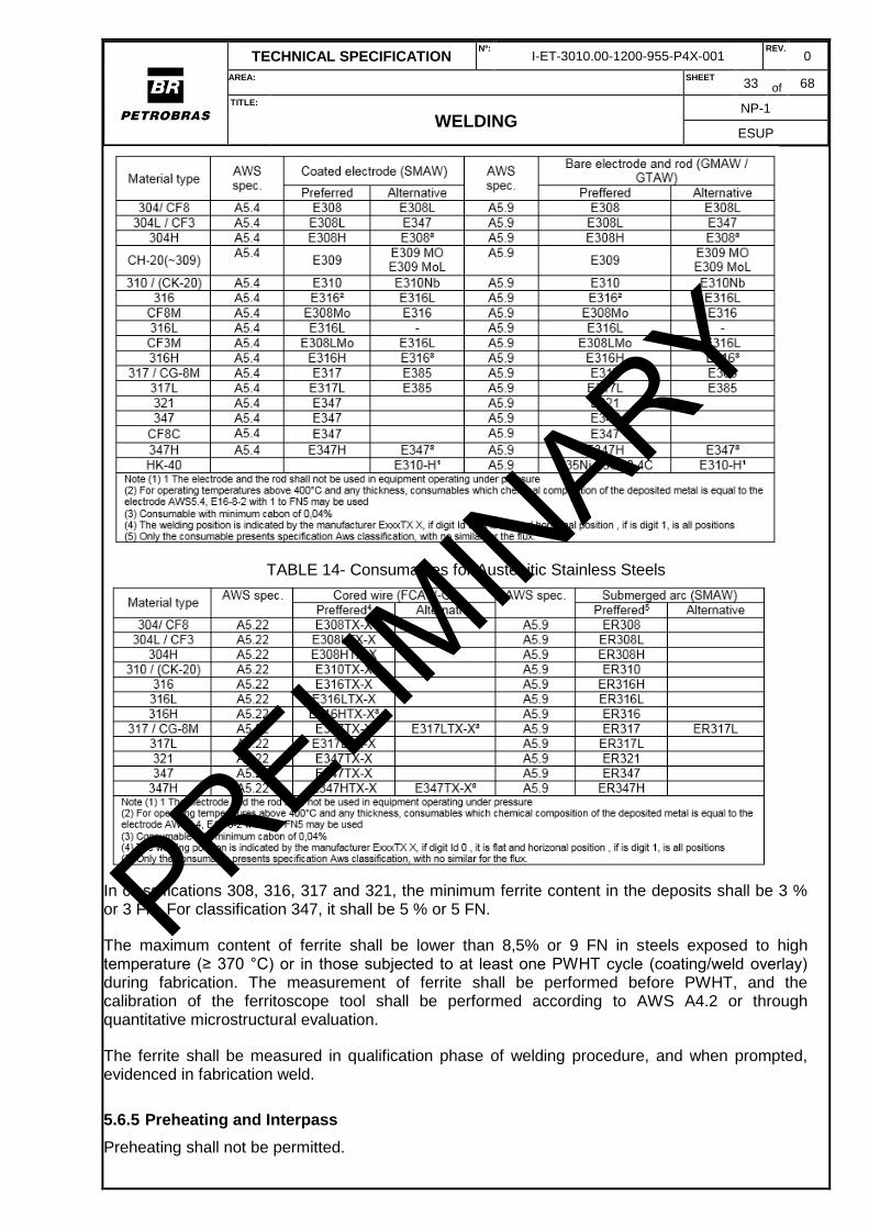
5.6.4 General Conditions for Consumables
The consumables shall follow the instructions in Tables 13 and 14. Alternative consumables shall
only be used with previous approval of PETROBRAS.
TABLE 13- Consumables for Austenitic Stainless Steels PRELIMIN
ARY
TECHNICAL SPECIFICATION Nº:
I-ET-3010.00-1200-955-P4X-001 REV.
0
AREA: SHEET 33 of 68
TITLE:
WELDING NP-1
ESUP
TABLE 14- Consumables for Austenitic Stainless Steels
In classifications 308, 316, 317 and 321, the minimum ferrite content in the deposits shall be 3 % or 3 FN. For classification 347, it shall be 5 % or 5 FN.
The maximum content of ferrite shall be lower than 8,5% or 9 FN in steels exposed to high temperature (≥ 370 °C) or in those subjected to at least one PWHT cycle (coating/weld overlay) during fabrication. The measurement of ferrite shall be performed before PWHT, and the calibration of the ferritoscope tool shall be performed according to AWS A4.2 or through quantitative microstructural evaluation.
The ferrite shall be measured in qualification phase of welding procedure, and when prompted, evidenced in fabrication weld.
5.6.5 Preheating and Interpass
Preheating shall not be permitted.
PRELIMIN
ARY
TECHNICAL SPECIFICATION Nº:
I-ET-3010.00-1200-955-P4X-001 REV.
0
AREA: SHEET 34 of 68
TITLE:
WELDING NP-1
ESUP
The interpass temperature shall be kept as low as possible and not exceed 150°C, except for the 317L steel, which shall not exceed 120ºC.
5.6.6 Post-Heating
It is not required.
5.6.7 Post Weld Heat Treatment (PWHT)
It is generally not required.
5.6.8 Weld Repair
More than two repairs in the same location may irreversibly degrade the corrosion resistance, due to precipitation of carbides or intermetallic phases. In this case, the joint shall be evaluated for the presence of precipitates, and, if their existence is evidenced, it shall be removed, including HAZ, and the section shall be replaced.
Before the authorization for repair welding, the surfaces to be welded shall be inspected with penetrant testing.
PRELIMIN
ARY
TECHNICAL SPECIFICATION Nº:
I-ET-3010.00-1200-955-P4X-001 REV.
0
AREA: SHEET 35 of 68
TITLE:
WELDING NP-1
ESUP
5.7 WELDING OF INCONEL 625 “WELD OVERLAY” CLAD PIPE
5.7.1 Scope
This section presents the welding requirements for Inconel 625 combined with carbon steel pipes in the form of “weld overlay”. Upon completion of the welding process, the minimum thickness of the deposition of Inconel 625 shall be 3.0 mm, as the example in Figure 5.
This section applies to:
a) Piping systems constructed using ASME B31.3 code: process piping;
b) Gas pipelines constructed according to ASME B31.8: gas transmission distribution and
piping systems (only topside interface at pig launcher and receiver system);
c) Oil pipelines constructed according to ASME B31.4: pipeline transportation systems for
liquid hydrocarbons and other liquids (only topside interface at pig launcher and receiver system);
d) Pressure vessels and other static equipment;
e) Piping valves and any other parts and accessories that need an overlay in order to protect
the base metal from corrosion.
5.7.2 Welding Processes
For welded overlay surface involving Inconel 625 and carbon steels (weld overlay process), the following welding processes may be used:
For welded overlay of carbon steels the following welding processes may be used:
Gas Tungsten Arc Welding (GTAW);
GTAW-Hot Wire (GTAW-Hot Wire, mechanized process);
Shielded Metal Arc Weling (SMAW);
Electro Slag Welding (ESW);
Submerged Arc Welding (SAW).
FCAW-G is not recommended for performing corrosion resistant weld overlay.
FCAW-S is forbidden for overlay and for butt welding.
5.7.3 Welding Consumables
Welding consumables shall be provided with the respective certificates of fabrication according to the applicable AWS standards. Classification of welding consumables shall be compatible with the following: NiCrMo-3.
Pipes and fittings over which the overlay will be deposited shall be supplied with a Material Certificates in accordance with EN 10204 item 3.1. Total traceability shall be guaranteed for the base materials and for the welding procedures.
PRELIMIN
ARY
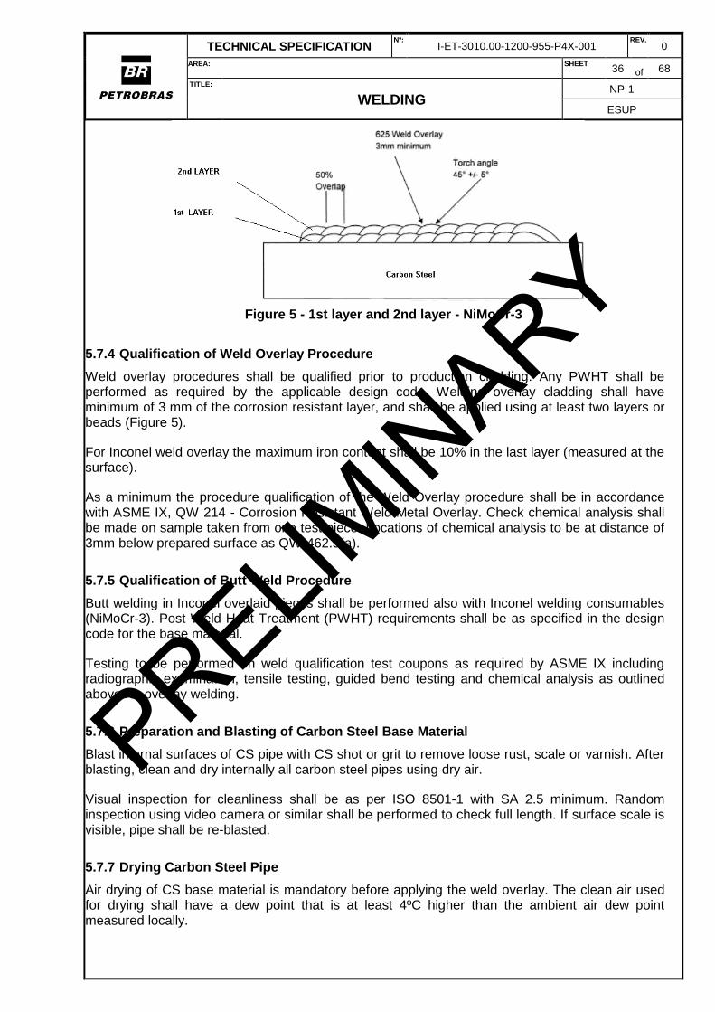
TECHNICAL SPECIFICATION Nº:
I-ET-3010.00-1200-955-P4X-001 REV.
0
AREA: SHEET 36 of 68
TITLE:
WELDING NP-1
ESUP
Figure 5 - 1st layer and 2nd layer - NiMoCr-3
5.7.4 Qualification of Weld Overlay Procedure
Weld overlay procedures shall be qualified prior to production cladding. Any PWHT shall be performed as required by the applicable design code. Welding overlay cladding shall have minimum of 3 mm of the corrosion resistant layer, and shall be applied using at least two layers or beads (Figure 5).
For Inconel weld overlay the maximum iron content shall be 10% in the last layer (measured at the surface).
As a minimum the procedure qualification of the Weld Overlay procedure shall be in accordance with ASME IX, QW 214 - Corrosion Resistant Weld Metal Overlay. Check chemical analysis shall be made on sample taken from one test piece. Locations of chemical analysis to be at distance of 3mm below prepared surface as QW-462.5(a).
5.7.5 Qualification of Butt Weld Procedure
Butt welding in Inconel overlaid pieces shall be performed also with Inconel welding consumables (NiMoCr-3). Post Weld Heat Treatment (PWHT) requirements shall be as specified in the design code for the base material.
Testing to be performed on weld qualification test coupons as required by ASME IX including radiographic examination, tensile testing, guided bend testing and chemical analysis as outlined above for overlay welding.
5.7.6 Preparation and Blasting of Carbon Steel Base Material
Blast internal surfaces of CS pipe with CS shot or grit to remove loose rust, scale or varnish. After blasting, clean and dry internally all carbon steel pipes using dry air.
Visual inspection for cleanliness shall be as per ISO 8501-1 with SA 2.5 minimum. Random inspection using video camera or similar shall be performed to check full length. If surface scale is visible, pipe shall be re-blasted.
5.7.7 Drying Carbon Steel Pipe
Air drying of CS base material is mandatory before applying the weld overlay. The clean air used for drying shall have a dew point that is at least 4ºC higher than the ambient air dew point measured locally.
PRELIMIN
ARY
TECHNICAL SPECIFICATION Nº:
I-ET-3010.00-1200-955-P4X-001 REV.
0
AREA: SHEET 37 of 68
TITLE:
WELDING NP-1
ESUP
5.7.8 NDT – Non Destructive Examination
5.7.8.1 Internal Cladding:
a) 100% Visual Inspection of all pieces and video camera examination of all internal weld surface.
b) Dye Penetrant Test on all accessible areas of weld overlay cladding. Water washable penetrant permissible.
c) PMI of weld overlay, where accessible;
Acceptance Criteria
a) Smooth overlay surface fully & continuously welded;
b) API 6A PSL2 for surface NDE. The following acceptance criteria apply:
(i) No relevant linear indications;
(ii) No relevant rounded indication with major dimension equal or greater than 5 mm;
(iii) Four or more relevant rounded indications in a line separated by1.6mm or less (edge to edge) are unacceptable;
(iv) No relevant indications in pressure contact sealing surfaces (e.g. flange gasket faces).
5.7.8.2 Base Metal - External:
a) 100% manual UT examination for lack of bond and sub-surface discontinuities on clad piece (scanned from external surface) using straight beam, contact and pulse echo ultrasonic technique in accordance with ASME V Article5. Primary reference level set using calibration block with FBH;
b) Longitudinal & Transverse Defects 100% manual UT of outer surface and volume;
c) Visual Examination of outer surface post welding.
Acceptance Criteria.
a) As per API 6A. No single indication exceeding reference level. No multiple indications exceeding 50% of reference level. Multiple indications are defined as two or more indications (each exceeding 50% of the reference level) within 13mm of each other in any direction.
b) No dents greater than 6.4mm (as gap between lowest point of dent and prolongation of original contour). Cold formed dent deeper than 3.2mm with sharp bottom gouge is a defect (may be removed by grinding). All cracks, sweats and leaks are defects. Nil deleterious arc burns. No OD surface imperfections with depth greater than 12.5% of specified CS3. Visual examination. Wall thickness. Refer API 5L.
5.7.8.3 Bevelled Ends:
Liquid Penetrant Test of ends after beveling. Test method per ASTM E165 per API 6A PSL2.
PRELIMIN
ARY
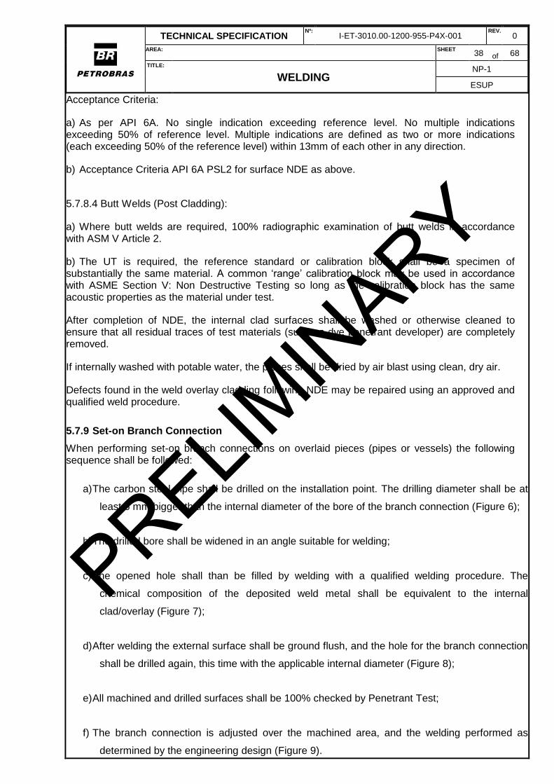
TECHNICAL SPECIFICATION Nº:
I-ET-3010.00-1200-955-P4X-001 REV.
0
AREA: SHEET 38 of 68
TITLE:
WELDING NP-1
ESUP
Acceptance Criteria:
a) As per API 6A. No single indication exceeding reference level. No multiple indications exceeding 50% of reference level. Multiple indications are defined as two or more indications (each exceeding 50% of the reference level) within 13mm of each other in any direction.
b) Acceptance Criteria API 6A PSL2 for surface NDE as above.
5.7.8.4 Butt Welds (Post Cladding):
a) Where butt welds are required, 100% radiographic examination of butt welds in accordance with ASM V Article 2.
b) The UT is required, the reference standard or calibration block shall be a specimen of substantially the same material. A common ‘range’ calibration block may be used in accordance with ASME Section V: Non Destructive Testing so long as the calibration block has the same acoustic properties as the material under test.
After completion of NDE, the internal clad surfaces shall be washed or otherwise cleaned to ensure that all residual traces of test materials (such as dye penetrant developer) are completely removed.
If internally washed with potable water, the pieces shall be dried by air blast using clean, dry air.
Defects found in the weld overlay cladding following NDE may be repaired using an approved and qualified weld procedure.
5.7.9 Set-on Branch Connection
When performing set-on branch connections on overlaid pieces (pipes or vessels) the following sequence shall be followed:
a) The carbon steel pipe shall be drilled on the installation point. The drilling diameter shall be at
least 6 mm bigger than the internal diameter of the bore of the branch connection (Figure 6);
b) The drilled bore shall be widened in an angle suitable for welding;
c) The opened hole shall than be filled by welding with a qualified welding procedure. The
chemical composition of the deposited weld metal shall be equivalent to the internal
clad/overlay (Figure 7);
d) After welding the external surface shall be ground flush, and the hole for the branch connection
shall be drilled again, this time with the applicable internal diameter (Figure 8);
e) All machined and drilled surfaces shall be 100% checked by Penetrant Test;
f) The branch connection is adjusted over the machined area, and the welding performed as
determined by the engineering design (Figure 9).
PRELIMIN
ARY
TECHNICAL SPECIFICATION Nº:
I-ET-3010.00-1200-955-P4X-001 REV.
0
AREA: SHEET 39 of 68
TITLE:
WELDING NP-1
ESUP
PRELIMIN
ARY
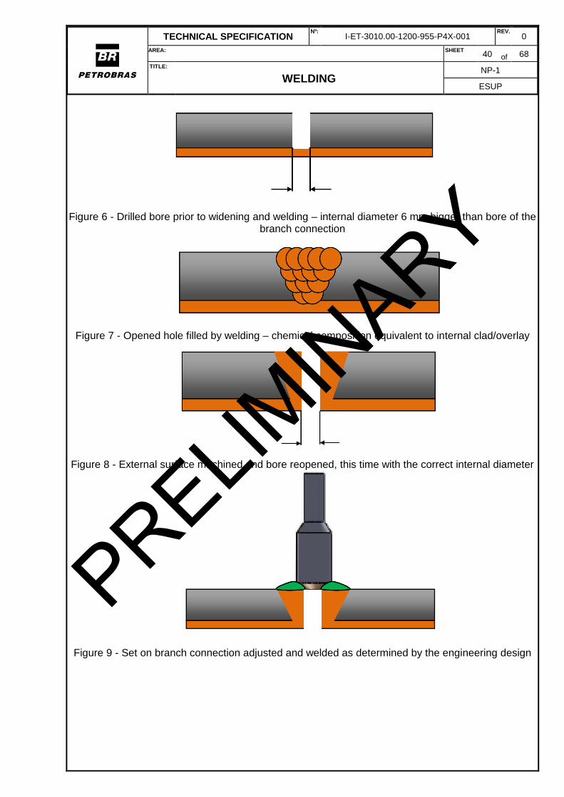
TECHNICAL SPECIFICATION Nº:
I-ET-3010.00-1200-955-P4X-001 REV.
0
AREA: SHEET 40 of 68
TITLE:
WELDING NP-1
ESUP
Figure 6 - Drilled bore prior to widening and welding – internal diameter 6 mm bigger than bore of the branch connection
Figure 7 - Opened hole filled by welding – chemical composition equivalent to internal clad/overlay
Figure 8 - External surface machined and bore reopened, this time with the correct internal diameter
Figure 9 - Set on branch connection adjusted and welded as determined by the engineering design
PRELIMIN
ARY
TECHNICAL SPECIFICATION Nº:
I-ET-3010.00-1200-955-P4X-001 REV.
0
AREA: SHEET 41 of 68
TITLE:
WELDING NP-1
ESUP
5.7.10 Positive Material Identification (PMI)
Positive Material Identification (PMI) testing performed using portable XRF alloy analyzer (Innov-X Alpha) on one accessible area of finished overlay cladding at sampling rate of one reading per component (one per pipe, one per flange, one per bend). Material grade identification is based on Ni, Mo, Cr, Fe content using Innov-X analyser standard accuracy and integral material grade library.
In cases where PMI testing of the weld deposit is not possible because of the geometry of the item being tested, the verification of the welding wire identification markings is an acceptable substitute.
PMI testing may be performed either during or after production cladding operations.
Note: Welding wire material grade is verified during production by lot testing weld overlay instead of PMI testing.
Acceptance Criteria:
Positive Material Identification (PMI) testing to positively confirm the composition of the weld overlay cladding conforms to material grade Alloy 625 UNS N06625 (Inconel 625).
PMI data readings from the analyser to be retained after testing (internal records only).
Where material verification is performed with acceptable results, the statement “PMI satisfactory” shall be noted on the relevant finished product material test certificates.
5.7.11 Pipe End Finish
Pipe ends shall be supplied beveled to ASME/ANSI B16.25 with weld overlay cladding continuous up to the pipe end.
Pipe ends to be beveled after weld overlay cladding of internal pipe bore to avoid shrinkage effects and maintain dimensions.
Where required for girth welding, pipe end bevels shall be ‘buttered’ by manual GTAW welding to apply a 3mm thick layer of UNS N06625.
Acceptance Criteria.
Smooth surface finish. Where machined, surface finish to be free from visible tool chatter marks, burrs or flat areas.
5.7.12 Copper Sulphate Solution Test
Where contamination of the weld overlay is suspected, copper sulphate test is performed per ASTM A380, subject to HSE restrictions, on accessible finished overlay surfaces shall be performed to check for the presence of free iron.
Prepare copper sulphate solution as per ASTM A380, swab or spray the surface of the overlay with copper sulphate solution, keep wet with additional solution if necessary and leave for a minimum of 6 minutes. Rinse with potable water spray (with less than 50 ppm chloride in the water) and air dry. Visually examine for signs of copper deposit that indicate the presence of free iron.
PRELIMIN
ARY
TECHNICAL SPECIFICATION Nº:
I-ET-3010.00-1200-955-P4X-001 REV.
0
AREA: SHEET 42 of 68
TITLE:
WELDING NP-1
ESUP
Note: in the case that Liquid Penetrant Test inspection is not possible, copper sulphate solution testing shall be performed per ASTMA380 and appraised by video camera to verify that the cladding is continuous and that no base metal is exposed to fluids in service.
Acceptance Criteria.
ASTM A380 Copper Sulphate Test: states
“This test is hypersensitive and shall be used and interpreted only by personnel familiar with its limitations”. Posttest evaluation and determination of disposition by experienced personnel only.
If copper deposits are detected, the overlay surface is to be locally pickled and passivated to remove free iron surface contamination before being re-tested and re-examined.
5.7.13 Final Inspection
Final inspection of each pipe shall include100% visual check of the physical condition of the internal & external surfaces of each pipe external surfaces of pipes shall be free from:
a) All dents greater than 6.4mm;
b) Cold formed dents deeper than 3.2mm (with sharp bottom gouge);
c) Cracks, sweats and leaks;
d) Arc burns.
e) Surface imperfections on outside diameter with depth >12.5% of nominal CS wall.
f) Cutting chips Weld overlay clad pipe to be supplied in clean “as welded” condition (without
pickling).
g) Weld overlay surface (visual assessment).
Acceptance Criteria.
Visual internal and external examination.
Refer API 5L. Unacceptable surface imperfections may be removed by machining or grinding to sound metal and the repaired area blended into the contour of the pipe so long as the remaining CS wall thickness is kept above the minimum CS wall thickness. Internal overlay clad surface shall be visibly free of dirt, grease, oil or other contaminants Weld overlay surface shall have a smooth appearance and be continuous without interruption. Average peak to trough height between adjacent beads less than 1mm, except for overlapping areas (start-stop, and so on).
No gaps of any width between the weld beads are permitted. Overlapping weld beads with locally increased deposit thickness are allowed provided the minimum cladding thickness requirement is met and that NDE of the weld overlay is satisfactory.
5.7.14 Recommended Practices for “Butt Welding joints” Procedure Specification (WPS)
This item establishes the recommended practices for prepare and qualify the butt welding joints procedure specification (WPS). However, all welding documents shall be prepared and qualified by a welding inspector qualified.
For welding pipe to pipe or pipe to fittings joint´s (butt-welding joint´s), can be used gas -tungsten-arc (GTAW - manual process) and SMAW process.
a) Root : Gas -Tungsten-arc (GTAW - manual process);
PRELIMIN
ARY
TECHNICAL SPECIFICATION Nº:
I-ET-3010.00-1200-955-P4X-001 REV.
0
AREA: SHEET 43 of 68
TITLE:
WELDING NP-1
ESUP
b) Reinforcement pass : Gas -Tungsten-arc (GTAW - manual process);
c) Filling pass: SMAW process;
d) Finishing pass: SMAW process.
Qualification of GTAW / SMAW Butt Weld WPS to be performed using multiple layer ERNiMoCr-3 welding consumable in accordance with the requirements of ASME B31.3 and ASME IX.
Base material used for the weld qualification shall be from same material grouping as API 5L and ASTM A694 F60 (ASME IX QW-422).
Testing to be performed on weld qualification test coupons as required by ASME IX including radiographic examination, tensile testing, guided bend testing, chemical analysis and corrosion testing as outlined above.
Note: Change of filler metal brand name and manufacturing location are not considered essential variables.
Consumable
a) Specifications: AWS A 5.11;
b) Specifications: AWS A 5.14;
c) Classifications: ER Ni Cr Mo-3;
Gas
a) shielding – argon - 99,99 %;
b) backing – argon – 99,99% (if applicable).
Acceptance Criteria
If any testing additional to the under mentioned requirements is undertaken during testing of the actual procedure qualification, the additional test results can be included in the resultant final PQR but strictly for information only.
As required, where the butt weld is to be completed using ERNiCrMo-3 consumable for all weld passes, the clad pipe bevel may be pre butte reducing 3mm thick layer of Alloy 625 UNS N06625, applied using manual GTAW in accordance with approved weld procedure, so as to ensure that the root pass of the butt weld is not diluted with Fe.
PRELIMIN
ARY
TECHNICAL SPECIFICATION Nº:
I-ET-3010.00-1200-955-P4X-001 REV.
0
AREA: SHEET 44 of 68
TITLE:
WELDING NP-1
ESUP
5.8 WELDING OF OTHER METALS AND ALLOYS
The welding of metals and alloys other than the ones herein cited shall follow the applicable requirements of API 582 and NORSOK M-601.
Welding of Titanium shall be as stablished in Annex O.
PRELIMIN
ARY
TECHNICAL SPECIFICATION Nº:
I-ET-3010.00-1200-955-P4X-001 REV.
0
AREA: SHEET 45 of 68
TITLE:
WELDING NP-1
ESUP
ANNEX A (INFORMATIVE-NONMANDATORY)
A - INSTRUCTIONS FOR THE ELABORATION OF THE WELDING PROCEDURE AND
TESTING SCHEDULE (WPTS)
A.1 GENERAL CONDITIONS
A.1.1 Welding parameters in the WPTS shall be based on the values specified in the qualified welding procedure and on the tolerances permitted in applicable qualification standards.
A.1.2 The WPTS shall be detailed for each joint to be welded. However, when the quantity of weldments is so high that individualization is impracticable or unsuitable, identical joints may be grouped. In any case, the individual joint shall be traceable to its applicable welding procedure.
A.2 SPECIFIC CONDITIONS
The WPTS shall contain at least, the information described in items A.2.1 to A.2.3.
A.2.1 Number of drawing and identification of the equipment, piping or structure to be welded, indicating location of joints.
A.2.2 Individual identification of joint or group of joints to be welded, as described in item A.1.2.
A.2.3 Specific information on welding execution and inspection for joint or group of joints, that is:
a) identification of welding procedure (WPS/PQR);
b) joint design and symbols for welding in accordance with standard AWS A2.4;
c) specification of base metal, diameter (if applicable), and thickness of each member of joint;
d) welding sequence;
e) welding parameters, cited for each weld pass, that is: - welding process; - classification, trademark, and diameter of welding electrodes, wires, or rods; - type and intensity of current; - speed (if applicable) voltage and polarity; - classification and trademark of fluxes (if applicable); - type and flow rate of purge and shielding gases (if applicable); - deposition technique (if applicable) stringer or weave bead and indication of minimum or maximum value for width of pass; - position and progression of welding (if applicable);
f) initial and interpass cleaning method;
g) gouging technique (if applicable);
h) pre-heating temperature and technique of application;
i) interpass temperature;
j) post-heating time and temperature and technique of application (if applicable);
k) indication of whether or not postweld heat treatment is required and identification of execution procedure (if applicable);
l) instruction regarding waiting period before non-destructive tests;
m) type and extension of non-destructive and other applicable tests, as well as the definition of hold points (before or after the root pass, at each layer, before or after postweld heat treatment);
n) reference standard, including the fabrication standard and the standard to acceptance criteria
PRELIMIN
ARY
TECHNICAL SPECIFICATION Nº:
I-ET-3010.00-1200-955-P4X-001 REV.
0
AREA: SHEET 46 of 68
TITLE:
WELDING NP-1
ESUP
with the applicable item;
o) process data as: kind of fluid, pressure class and temperature (if applicable).
PRELIMIN
ARY
TECHNICAL SPECIFICATION Nº:
I-ET-3010.00-1200-955-P4X-001 REV.
0
AREA: SHEET 47 of 68
TITLE:
WELDING NP-1
ESUP
ANNEX B (INFORMATIVE-NONMANDATORY)
B - INSTRUCTIONS FOR THE ELABORATION OF THE WELDER AND WELDING
OPERATOR PERFORMANCE CONTROL REPORT (WPCR)
B.1 GENERAL CONDITIONS
B.1.1 A WPCR shall be issued at time intervals that comply with the criteria in equipment design or fabrication and assembly standards or in contract documents.
B.1.2 Two separate control sheets shall be drawn up, one for radiographs and another for ultra-sound.
B.2 SPECIFIC CONDITIONS
The WPCR shall contain at least:
a) welder or welding operator identification code;
b) total number or radiographs taken or total length inspected during a certain period, as applicable;
c) total number of failed radiographs or sum of flawed lengths during a certain period, as applicable;
d) percentage of flaws, calculated by dividing the figure cited in paragraph c) supra by the figure cited in paragraph b) and then multiplying by 100 (one hundred);
e) accumulated amounts for paragraphs b), c), and d) supra, through the date of issue of the WPCR;
f) accumulated amount for paragraph d) in the previous WPCR.
PRELIMIN
ARY
TECHNICAL SPECIFICATION Nº:
I-ET-3010.00-1200-955-P4X-001 REV.
0
AREA: SHEET 48 of 68
TITLE:
WELDING NP-1
ESUP
ANNEX C (INFORMATIVE-NONMANDATORY)
C - INSTRUCTIONS FOR THE ELABORATION OF THE POSTWELD HEAT TREATMENT
REPORTS (PWHTR)
C.1 GENERAL CONDITIONS
The PWHTR is applicable to the recording of post weld heat treatments of test pieces, and in the fabrication, assembly, and maintenance of equipment, piping and any other metallic materials, when required under items of this Technical Specification.
C.2 SPECIFIC CONDITIONS
The PWHTR shall contain at least the following information:
a) type of post weld heat treatment executed;
b) identification of applicable heat treatment procedure;
c) identification of applicable execution standard;
d) execution parameters, that is: - initial and final control temperatures; - minimum and maximum heating rates; - minimum and maximum treatment temperatures; - minimum and maximum treatment times; - minimum and maximum cooling rates; - maximum temperature difference between thermocouples;
e) identification of equipment or test piece;
f) identification (serial number) of temperature recorder used;
g) identification, date of issue, and name of the entity issuing calibration report for the temperature recorder and thermocouples used;
h) indication of execution method, that is: - furnace heat treatment; - local heat treatment.
i) indication of means of heating used;
j) sketch of furnace (if applicable), indicating location of equipment inside, of jet burners, and of electrical equipment inside, of jet burners, and of electrical resistances as well as the overlap regions whenever the equipment is not fully inside the furnace;
k) sketch of the welding joint, indicating location and distribution of electrical resistances and width of the soak band, heated band and control gradient band, whenever local heat treatment is performed;
l) type, quantity, and identification (number and color on graph) of thermocouples used;
m) method for attaching thermocouples to part;
n) sketch of equipment or test piece, indicating identification, location, and relative distance between thermocouples;
o) record of test piece temperature versus time (time x temperature graph), with identification of thermocouples used;
p) final technical statement, concluding whether the heat treatment was executed in accordance with the applicable procedure and standards.
PRELIMIN
ARY
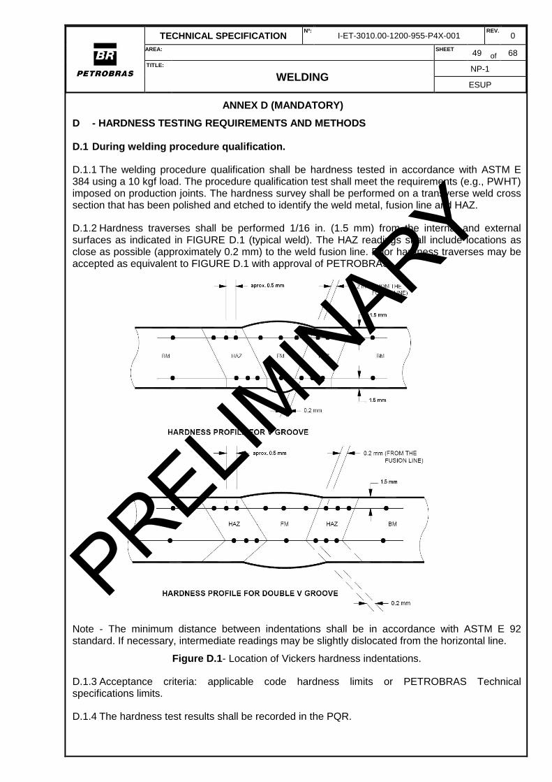
TECHNICAL SPECIFICATION Nº:
I-ET-3010.00-1200-955-P4X-001 REV.
0
AREA: SHEET 49 of 68
TITLE:
WELDING NP-1
ESUP
ANNEX D (MANDATORY)
D - HARDNESS TESTING REQUIREMENTS AND METHODS
D.1 During welding procedure qualification.
D.1.1 The welding procedure qualification shall be hardness tested in accordance with ASTM E 384 using a 10 kgf load. The procedure qualification test shall meet the requirements (e.g., PWHT) imposed on production joints. The hardness survey shall be performed on a transverse weld cross section that has been polished and etched to identify the weld metal, fusion line and HAZ.
D.1.2 Hardness traverses shall be performed 1/16 in. (1.5 mm) from the internal and external surfaces as indicated in FIGURE D.1 (typical weld). The HAZ readings shall include locations as close as possible (approximately 0.2 mm) to the weld fusion line. Prior hardness traverses may be accepted as equivalent to FIGURE D.1 with approval of PETROBRAS.
Note - The minimum distance between indentations shall be in accordance with ASTM E 92 standard. If necessary, intermediate readings may be slightly dislocated from the horizontal line.
Figure D.1- Location of Vickers hardness indentations.
D.1.3 Acceptance criteria: applicable code hardness limits or PETROBRAS Technical specifications limits.
D.1.4 The hardness test results shall be recorded in the PQR.
PRELIMIN
ARY
TECHNICAL SPECIFICATION Nº:
I-ET-3010.00-1200-955-P4X-001 REV.
0
AREA: SHEET 50 of 68
TITLE:
WELDING NP-1
ESUP
D.2 During welding production.
D.2.1 Pressure-retaining welds shall be hardness tested in accordance with requirements given below:
D.2.1.1 Weld deposits shall be hardness tested, where required, on the side contacted by the process fluid whenever possible. If access to the process side is impractical, such as on piping or small diameter vessels, hardness testing shall be done on the opposite side.
D.2.1.2 Readings in the HAZ shall be conducted if specified by the applicable code (e.g., B31.3) or by this technical specification.
D.2.1.3 Testing shall be performed after any required PWHT.
D.2.1.4 The test location and frequency shall be in accordance with item D.3 unless otherwise specified by the applicable code/standard or as required by PETROBRAS Technical Specifications.
D.2.2 When hardness testing is required, it shall be performed according to ASTM E 384 standard.
D.2.3 Portable instruments may be used also. To use portable instrument, it shall be previously demonstrated the instrument suitability to test performance. This shall be done performing hardness measurements with the portable instrument in a welded joint of material of same applicable specification (ASTM, ASME) of that of the equipment to be tested, indentations according to Figure H.1, and comparing the obtained values with the hardness measurements values performed in adjacent positions with a bench instrument in accordance with ASTM E 384 standard, Vickers hardness method, HV 5 or HV 10. If these last hardness measurement values are similar to those obtained in adjacent positions with the portable instrument, this last one is considered as adequate for hardness measurements.
Note: Comparisons between measurements carried on hardness calibration blocks shall not be permitted to establish the portable instrument suitability for hardness measurement.
D.2.4 The similarity corroboration, between bench and portable instruments, shall be previously presented to PETROBRAS, for approval. The portable instrument shall be previously approved by PETROBRAS.
D.2.5 Unless otherwise agreed between the MANUFACTURER / PACKAGER and PETROBRAS, the maximum allowable hardness for welds shall be:
a) P-1, P-3, and P-4 materials: 225 HB/ HV5/HV10;
b) P-5A, P-5B Group 1 and P-5C materials: 241 HB/ HV5/HV10.
Note: Limitation of P-5B Group 2 to be as agreed between PETROBRAS and MANUFACTURER / PACKAGER.
D.2.6 Weld deposits found to exceed the maximum hardness criterion in D.2.5 are unacceptable and shall be reported to PETROBRAS. Unless accepted by the PETROBRAS, harder welds shall be either removed or rewelded or heat treated to reduce the hardness to an acceptable value. The specific approach to be used to correct the high-hardness condition shall be subject to the PETROBRAS approval before any corrective action is taken. Regardless of the method of corrective action taken, the weld deposits shall be retested to ensure that the corrective action has resulted in acceptable hardness values. Also, additional welds should be hardness tested for each high hardness weld that is found, at a rate determined by PETROBRAS.
PRELIMIN
ARY
TECHNICAL SPECIFICATION Nº:
I-ET-3010.00-1200-955-P4X-001 REV.
0
AREA: SHEET 51 of 68
TITLE:
WELDING NP-1
ESUP
D.2.7 When not otherwise specified inspect furthermore 4 (four) weld joints of same material for each detected weld joint with unacceptable hardness values.
D.2.8 Hardness test results and locations shall be recorded.
D.3 The test location and frequency
D.3.1 For vessel or tank butt welds where hardness testing is required, a minimum of one location per weld seam shall be hardness tested. Unless otherwise specified by design code requirements, one hardness test shall be made for each 3 m (10 ft) of weld seam. In addition, one hardness test shall be made on each nozzle flange-to-neck and nozzle neck-to-shell/head weld. Each unique welding procedure used shall be hardness tested.
D.3.2 When hardness testing of welds is required, fillet weld deposit hardness testing should be done when access is feasible. The number of hardness tests and locations required shall be approved by PETROBRAS with item D.3.1 as a guide.
D.3.3 For piping, hardness tests of production welds and of hot bent and hot formed piping are intended to verify satisfactory heat treatment. The hardness limit applies to the weld and to the heat affected zone (HAZ) tested as close as practicable to the edge of the weld:
(a) At least 10% of welds, hot bends, and hot formed components in each furnace heat treated batch and 100% of those locally heat treated shall be tested, unless otherwise specified by design code requirements.
(b) When dissimilar metals are joined by welding, the hardness limits specified for the base and welding materials shall be met for each material.
D.3.4 Repair welds in cast, forged, or plate components shall be hardness tested, when required, in accordance with the following requirements:
a) Hardness testing shall be performed on each component that has been weld repaired;
b) At least one hardness test shall be performed for each unique welding process/filler metal heat number combination used on the component;
c) Hardness testing shall be performed on actual weld repairs when the weld repair area is accessible, large enough to accommodate an indentation, and in a location where an indentation can be tolerated;
d) When actual weld repairs cannot be hardness tested, weld test patches shall be created on an accessible area of the component to allow hardness testing. PRELIM
INARY
TECHNICAL SPECIFICATION Nº:
I-ET-3010.00-1200-955-P4X-001 REV.
0
AREA: SHEET 52 of 68
TITLE:
WELDING NP-1
ESUP
ANNEX E (RECOMMENDATION - NONMANDATORY)
E - RECOMMENDATIONS FOR WELDING REPAIR
E.1 Minor surface repairs
E.1.1 Minor surface imperfections or damage on welded joints may be removed by grinding provided that the remaining wall thickness at any point is not less than minimum specified wall thickness.
E.1.2 The ground area shall be carefully dressed to ensure a smooth transition with the surrounding surface, with no notches.
E.1.3 The ground areas shall be MT or PT inspected to ensure that the defects have been removed.
E.2 Welding repairs
E.2.1 Welding repairs shall be according to item 7 of NORSOK M-601 - Welding and inspection of piping.
E.2.2 Where a different welding repair procedure is to be used, the welding procedure shall be qualified.
E.2.3 The MANUFACTURER / PACKAGER shall make every effort to minimize the residual stresses resulting from the repair.
E.2.4 All repair work shall be carried out by qualified welders.
E.2.5 Repair welding shall be avoided after any PWHT that may be required, or after hydrostatic test. If any weld repair is required after PWHT or hydrostatic test, the postweld heat treatment and hydrostatic test shall be repeated.
E.2.6 The MANUFACTURER / PACKAGER shall keep record of the weld repair rates per project on a weekly basis. Records shall be submitted to PETROBRAS for review.
E.2.7 Weld repair rates shall be calculated based on length welded and repaired.
E.3 NDT of repair welds
E.3.1 All weld repaired areas shall be ground to a smooth contour with the parent material or existing weld. Care shall be taken to ensure that over-grinding does not occur and that the minimum wall thickness is maintained.
E.3.2 The weld-repaired area shall be subject to 100% examination, after the PWHT if any, using the same techniques and acceptance criteria used for original examination.
E.3.3 If during final examination further defects are detected then the total welded joint area shall be examined. If a second repair is necessary the PETROBRAS prior approval is required before the repair.
E.3.4 The PETROBRAS and/or Classification Society shall witness all stages of the weld repair and NDT.
PRELIMIN
ARY
TECHNICAL SPECIFICATION Nº:
I-ET-3010.00-1200-955-P4X-001 REV.
0
AREA: SHEET 53 of 68
TITLE:
WELDING NP-1
ESUP
ANNEX F (MANDATORY)
F - ADDITIONAL REQUIREMENTS FOR DUPLEX WELD PROCEDURE QUALIFICATION
F.1 REQUIREMENTS FOR WELDING AND PREPARATION OF TEST COUPONS
Welding procedures for duplex stainless steels shall be qualified for all welded joints in accordance with ASME Section IX and the additional requirements of this ANNEX.
The MANUFACTURER / PACKAGER shall draw up the WPS, joint type, size, material and position that are to be used to weld the qualification test pieces. PETROBRAS shall be given the opportunity to review and comment on the WPS prior starting welding.
The welding of coupons shall be undertaken on identified traceable materials using suitable identified and traceable welding consumables. Approved welding consumables only shall be used.
The WPS shall be available to the welders at the time and place of welding.
Procedure documentation, including the final WPS (which may be modified from the original submission according to the parameters actually used during qualification) shall be submitted to the PETROBRAS for final approval.
The welding of coupons shall be witnessed by authorized inspector.
The following welding parameters shall be recorded as a minimum (for all weld metal deposited):
Process;
Welding current (I);
Arc voltage (V);
Travel speed (TS);
Heat input (arc energy) (HI);
Interpass temperature;
Percentage of oxygen in backing gas. (At the start of welding);
Welding consumable batch number.
Heat input shall be calculated by equation:
TS
IVHI
1000
60
Where TS is in mm/min.
Run out length and arc time shall be recorded.
Reading shall be taken for each individual arc time even though any pass may contain two or more arc times. Suitably calibrated equipment, approved by PETROBRAS, shall be used to monitor the welding.
The following qualification data shall be recorded:
Date;
Test piece identification;
WPS number;
Material identification;
Welding consumable identity;
Monitoring equipment;
Actual joint configuration;
Welding parameters;
PRELIMIN
ARY
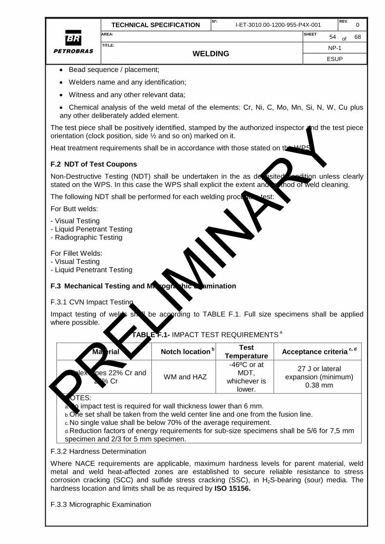
TECHNICAL SPECIFICATION Nº:
I-ET-3010.00-1200-955-P4X-001 REV.
0
AREA: SHEET 54 of 68
TITLE:
WELDING NP-1
ESUP
Bead sequence / placement;
Welders name and any identification;
Witness and any other relevant data;
Chemical analysis of the weld metal of the elements: Cr, Ni, C, Mo, Mn, Si, N, W, Cu plus any other deliberately added element.
The test piece shall be positively identified, stamped by the authorized inspector and the test piece orientation (clock position, side ½ and so on) marked on it.
Heat treatment requirements shall be in accordance with those stated on the WPS.
F.2 NDT of Test Coupons
Non-Destructive Testing (NDT) shall be undertaken in the as deposited condition unless clearly stated on the WPS. In this case the WPS shall explicit the extent and method of weld cleaning.
The following NDT shall be performed for each welding procedure test:
For Butt welds:
- Visual Testing - Liquid Penetrant Testing - Radiographic Testing
For Fillet Welds: - Visual Testing - Liquid Penetrant Testing
F.3 Mechanical Testing and Micrographic Examination
F.3.1 CVN Impact Testing
Impact testing of welds shall be according to TABLE F.1. Full size specimens shall be applied where possible.
TABLE F.1- IMPACT TEST REQUIREMENTS a
Material Notch location b
Test
Temperature Acceptance criteria
c, d
Duplex types 22% Cr and 25% Cr
WM and HAZ
-46ºC or at MDT,
whichever is lower.
27 J or lateral expansion (minimum)
0.38 mm
NOTES: a. No impact test is required for wall thickness lower than 6 mm. b. One set shall be taken from the weld center line and one from the fusion line. c. No single value shall be below 70% of the average requirement. d. Reduction factors of energy requirements for sub-size specimens shall be 5/6 for 7,5 mm specimen and 2/3 for 5 mm specimen.
F.3.2 Hardness Determination
Where NACE requirements are applicable, maximum hardness levels for parent material, weld metal and weld heat-affected zones are established to secure reliable resistance to stress corrosion cracking (SCC) and sulfide stress cracking (SSC), in H2S-bearing (sour) media. The
hardness location and limits shall be as required by ISO 15156.
F.3.3 Micrographic Examination
PRELIMIN
ARY
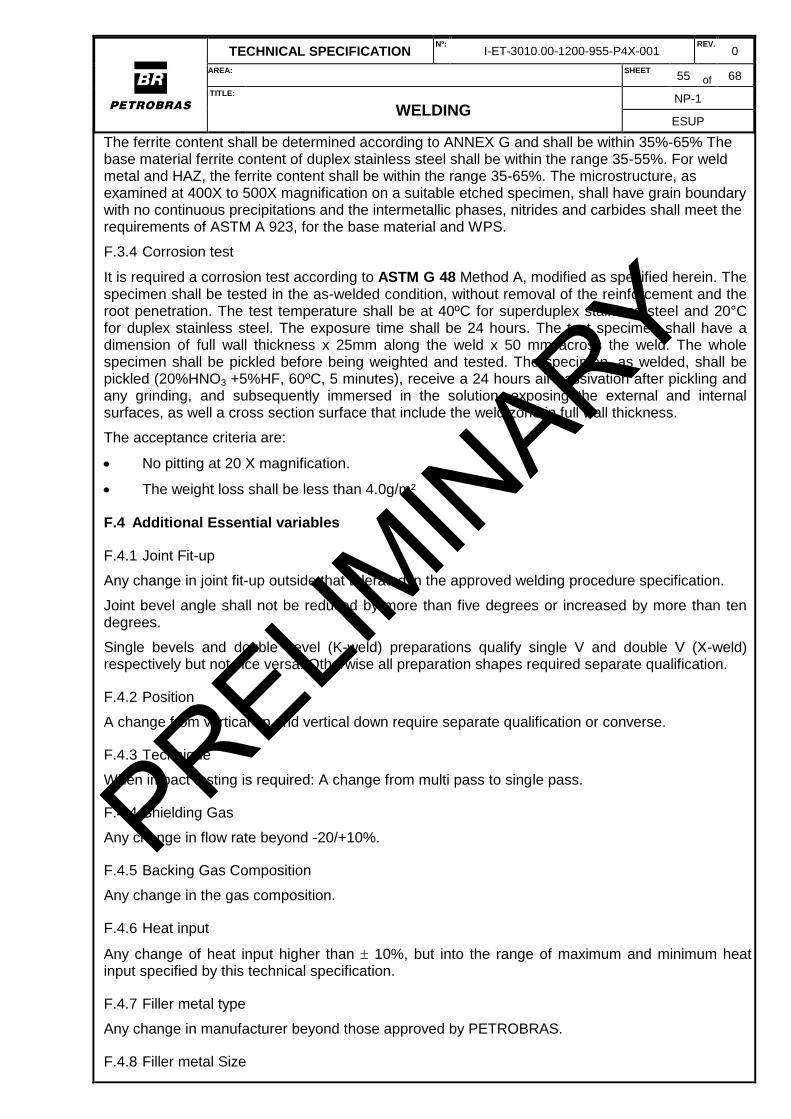
TECHNICAL SPECIFICATION Nº:
I-ET-3010.00-1200-955-P4X-001 REV.
0
AREA: SHEET 55 of 68
TITLE:
WELDING NP-1
ESUP
The ferrite content shall be determined according to ANNEX G and shall be within 35%-65% The base material ferrite content of duplex stainless steel shall be within the range 35-55%. For weld metal and HAZ, the ferrite content shall be within the range 35-65%. The microstructure, as examined at 400X to 500X magnification on a suitable etched specimen, shall have grain boundary with no continuous precipitations and the intermetallic phases, nitrides and carbides shall meet the requirements of ASTM A 923, for the base material and WPS.
F.3.4 Corrosion test
It is required a corrosion test according to ASTM G 48 Method A, modified as specified herein. The specimen shall be tested in the as-welded condition, without removal of the reinforcement and the root penetration. The test temperature shall be at 40ºC for superduplex stainless steel and 20°C for duplex stainless steel. The exposure time shall be 24 hours. The test specimen shall have a dimension of full wall thickness x 25mm along the weld x 50 mm across the weld. The whole specimen shall be pickled before being weighted and tested. The specimen, as welded, shall be pickled (20%HNO3 +5%HF, 60ºC, 5 minutes), receive a 24 hours air passivation after pickling and any grinding, and subsequently immersed in the solution, exposing the external and internal surfaces, as well a cross section surface that include the weld zone in full wall thickness.
The acceptance criteria are:
No pitting at 20 X magnification.
The weight loss shall be less than 4.0g/m²
F.4 Additional Essential variables
F.4.1 Joint Fit-up
Any change in joint fit-up outside that tolerated in the approved welding procedure specification.
Joint bevel angle shall not be reduced by more than five degrees or increased by more than ten degrees.
Single bevels and double bevel (K-weld) preparations qualify single V and double V (X-weld) respectively but not vice versa. Otherwise all preparation shapes required separate qualification.
F.4.2 Position
A change from vertical up and vertical down require separate qualification or converse.
F.4.3 Technique
When impact testing is required: A change from multi pass to single pass.
F.4.4 Shielding Gas
Any change in flow rate beyond -20/+10%.
F.4.5 Backing Gas Composition
Any change in the gas composition.
F.4.6 Heat input
Any change of heat input higher than 10%, but into the range of maximum and minimum heat input specified by this technical specification.
F.4.7 Filler metal type
Any change in manufacturer beyond those approved by PETROBRAS.
F.4.8 Filler metal Size
PRELIMIN
ARY

TECHNICAL SPECIFICATION Nº:
I-ET-3010.00-1200-955-P4X-001 REV.
0
AREA: SHEET 56 of 68
TITLE:
WELDING NP-1
ESUP
Any change in manufacturer beyond those approved by PETROBRAS.
PRELIMIN
ARY
TECHNICAL SPECIFICATION Nº:
I-ET-3010.00-1200-955-P4X-001 REV.
0
AREA: SHEET 57 of 68
TITLE:
WELDING NP-1
ESUP
ANNEX G (MANDATORY)
G MEASUREMENT OF FERRITE CONTENT FOR DUPLEX STAINLESS STEELS (MODIFIED
ASTM E 562)
G.1 INTRODUCTION:
For ferrite assessment during procedure qualification tests, metallurgical sections shall be polished and etched to clearly reveal the two-phase austenite/ferrite microstructure. The area being point counted, parent material, weld metal or HAZ, should be examined and photographed under a microscope at a sufficient magnification to fill the field of view and to be able to clearly discriminate between the constituent phases. (For parent plate and weld metal, a magnification of approximately X400 is required. For HAZ, about X700 to X1000 should be used).
G.2 METHODOLOGY:
G.2.1 The photographs shall be overlaid with a grid of at least 100 points and the percentage ferrite shall be calculated from the number of points that fall on the ferrite phase and the total number of points used. Automated counting methods using quantitative metallography equipment can also be used.
G.2.2 The ferrite content shall be measured on one of the metallurgical sections using the point counting technique at the following locations:
a. In the parent metal, one measurement on each side of the weld at mid thickness (total of 2). b. In the HAZ on each side of the weld, in the region of the root pass (total of 2). c. In the weld metal, three measurements near to the vertical center line of the weld, one in the cap, one in the root, and one at mid thickness (total of 3).
G.3 NOTES:
G.3.1 Representative microstructures of the weld (cap and root passes), fusion line, heat affected zone and parent material must be reported and shown as original photomicrographs and shall be attached to the relevant welding procedure qualification record.
G.3.2 Experience within the refining industry indicates that this is a difficult test (especially on HAZ) and results are often not accurate. Experienced laboratories addressed by PETROBRAS shall be used.
G.3.3 Only test laboratories which have a quality system in compliance with ISO 17025 or equivalent shall be used. PRELIM
INARY
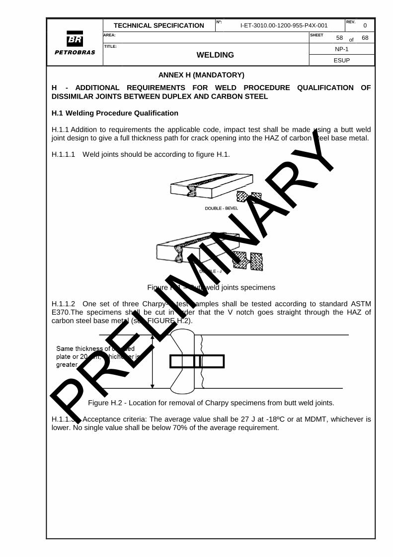
TECHNICAL SPECIFICATION Nº:
I-ET-3010.00-1200-955-P4X-001 REV.
0
AREA: SHEET 58 of 68
TITLE:
WELDING NP-1
ESUP
ANNEX H (MANDATORY)
H - ADDITIONAL REQUIREMENTS FOR WELD PROCEDURE QUALIFICATION OF
DISSIMILAR JOINTS BETWEEN DUPLEX AND CARBON STEEL
H.1 Welding Procedure Qualification
H.1.1 Addition to requirements the applicable code, impact test shall be made using a butt weld joint design to give a full thickness path for crack opening into the HAZ of carbon steel base metal.
H.1.1.1 Weld joints should be according to figure H.1.
Figure H.1 – Butt weld joints specimens
H.1.1.2 One set of three Charpy-V test samples shall be tested according to standard ASTM E370.The specimens shall be cut in order that the V notch goes straight through the HAZ of carbon steel base metal (see FIGURE H.2).
Figure H.2 - Location for removal of Charpy specimens from butt weld joints.
H.1.1.3 Acceptance criteria: The average value shall be 27 J at -18ºC or at MDMT, whichever is lower. No single value shall be below 70% of the average requirement. PRELIM
INARY
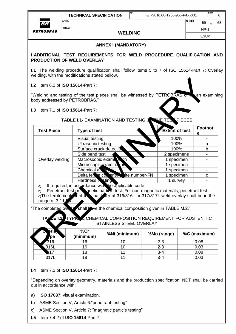
TECHNICAL SPECIFICATION Nº:
I-ET-3010.00-1200-955-P4X-001 REV.
0
AREA: SHEET 59 of 68
TITLE:
WELDING NP-1
ESUP
ANNEX I (MANDATORY)
I ADDITIONAL TEST REQUIREMENTS FOR WELD PROCEDURE QUALIFICATION AND
PRODUCTION OF WELD OVERLAY
I.1 The welding procedure qualification shall follow items 5 to 7 of ISO 15614-Part 7: Overlay welding, with the modifications stated bellow.
I.2 Item 6.2 of ISO 15614-Part 7:
“Welding and testing of the test pieces shall be witnessed by PETROBRAS or by an examining body addressed by PETROBRAS.”
I.3 Item 7.1 of ISO 15614-Part 7:
TABLE I.1- EXAMINATION AND TESTING OF THE TEST PIECES
Test Piece Type of test Extent of test Footnot
e
Overlay welding
Visual testing 100% -
Ultrasonic testing 100% a
Surface crack detection 100% b
Side bend test 2 specimens -
Macroscopic examination 1 specimen -
Microscopic examination 1 specimen -
Chemical analysis 1 specimen -
Delta ferrite content/Ferrite number-FN 1 specimen c
Hardness Testing 1 survey -
a) If required, in accordance with the applicable code. b) Penetrant test or magnetic particle test. For non-magnetic materials, penetrant test. c) The ferrite content of the final layer of 316/316L or 317/317L weld overlay shall be in the range of 3-11 FN.
“The completed overlay shall have the chemical composition given in TABLE M.2.”
TABLE I.2 - TYPICAL CHEMICAL COMPOSITION REQUIREMENT FOR AUSTENITIC STAINLESS STEEL OVERLAY
Overlay
type
%Cr
(minimum) %Ni (minimum) %Mo (range) %C (maximum)
316 16 10 2-3 0.08
316L 16 10 2-3 0.03
317 18 11 3-4 0.08
317L 18 11 3-4 0.03
I.4 Item 7.2 of ISO 15614-Part 7:
“Depending on overlay geometry, materials and the production specification, NDT shall be carried out in accordance with:
a) ISO 17637: visual examination,
b) ASME Section V, Article 6:“penetrant testing”
c) ASME Section V, Article 7: ”magnetic particle testing”
I.5 Item 7.4.2 of ISO 15614-Part 7:
PRELIMIN
ARY
TECHNICAL SPECIFICATION Nº:
I-ET-3010.00-1200-955-P4X-001 REV.
0
AREA: SHEET 60 of 68
TITLE:
WELDING NP-1
ESUP
“The test specimen shall be prepared and etched in accordance with on one side in order to reveal clearly the fusion line, the heat-affected zone (HAZ) and the building-up of the layers.”
I.6 Item 7.4.3 of ISO 15614-Part 7:
“The Vickers hardness testing with a load of Vickers number HV 10 or HV 5 shall be carried out in accordance with ASTM E384 - Standard Test Method for Knoop and Vickers Hardness of Materials. Hardness indentations shall be made as shown in Figure 5. The results of the hardness testing shall be in accordance with 7.5.2.3.”
I.7 Item 7.4.4 of ISO 15614-Part 7:
“Side bend test specimens and testing shall be in accordance with applicable code, when not
specified in the applicable code, ISO 5173 shall be used.”
I.8 Item 7.5.2.3 of ISO 15614-Part 7:
“The hardness values shall not exceed the values specified in applicable code or in this Technical Specification”.
PRELIMIN
ARY
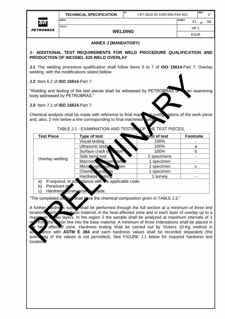
TECHNICAL SPECIFICATION Nº:
I-ET-3010.00-1200-955-P4X-001 REV.
0
AREA: SHEET 61 of 68
TITLE:
WELDING NP-1
ESUP
ANNEX J (MANDATORY)
J - ADDITIONAL TEST REQUIREMENTS FOR WELD PROCEDURE QUALIFICATION AND
PRODUCTION OF INCONEL 625 WELD OVERLAY
J.1 The welding procedure qualification shall follow items 5 to 7 of ISO 15614-Part 7: Overlay welding, with the modifications stated bellow.
J.2 Item 6.2 of ISO 15614-Part 7:
“Welding and testing of the test pieces shall be witnessed by PETROBRAS or by an examining body addressed by PETROBRAS.”
J.3 Item 7.1 of ISO 15614-Part 7:
Chemical analysis shall be made with reference to final machined configurations of the work piece and, also, 2 mm below a line corresponding to final machined surface.
TABLE J.1 - EXAMINATION AND TESTING OF THE TEST PIECES.
Test Piece Type of test Extent of test Footnote
Overlay welding
Visual testing 100% -
Ultrasonic testing 100% a
Surface crack detection 100% b
Side bend test 2 specimens -
Macroscopic examination 1 specimen -
Microscopic examination 1 specimen c
Chemical analysis 1 specimen -
Hardness Testing 1 survey -
a) If required, in accordance with the applicable code. b) Penetrant test. c) Hardness survey shall be made.
“The completed overlay shall have the chemical composition given in TABLE J.2.”
A further hardness survey shall be performed through the full section at a minimum of three test locations each: in the base material, in the heat-affected zone and in each layer of overlay up to a maximum of two layers. In the region 2 the sample shall be analyzed at maximum intervals of 1 mm from the fusion line into the base material. A minimum of three indentations shall be placed in the heat affected zone. Hardness testing shall be carried out by Vickers 10-Kg method in
accordance with ASTM E 384 and each hardness values shall be recorded separately (the averaging of the values is not permitted). See FIGURE J.1 below for required hardness test locations. PRELIM
INARY
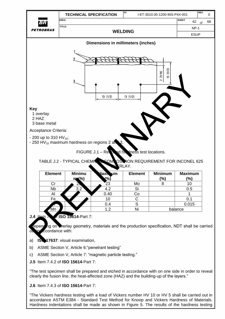
TECHNICAL SPECIFICATION Nº:
I-ET-3010.00-1200-955-P4X-001 REV.
0
AREA: SHEET 62 of 68
TITLE:
WELDING NP-1
ESUP
Dimensions in millimeters (inches)
Key 1 overlay 2 HAZ 3 base metal
Acceptance Criteria:
- 200 up to 310 HV10; - 250 HV10 maximum hardness on regions 2 and 3.
FIGURE J.1 – Required hardness test locations.
TABLE J.2 - TYPICAL CHEMICAL COMPOSITION REQUIREMENT FOR INCONEL 625 OVERLAY.
Element Minimu
m (%)
Maximum
(%)
Element Minimum
(%)
Maximum
(%)
Cr 20 23 Mo 8 10
Nb 3.2 4.2 Si 0.5
Al 0.40 Co 1
Fe 10 C 0.1
Ti 0.4 S 0.015
Mn 1.2 Ni balance
J.4 Item 7.2 of ISO 15614-Part 7:
“Depending on overlay geometry, materials and the production specification, NDT shall be carried out in accordance with:
a) ISO 17637: visual examination,
b) ASME Section V, Article 6:“penetrant testing”
c) ASME Section V, Article 7: “magnetic particle testing.”
J.5 Item 7.4.2 of ISO 15614-Part 7:
“The test specimen shall be prepared and etched in accordance with on one side in order to reveal clearly the fusion line, the heat-affected zone (HAZ) and the building-up of the layers.”
J.6 Item 7.4.3 of ISO 15614-Part 7:
“The Vickers hardness testing with a load of Vickers number HV 10 or HV 5 shall be carried out in accordance ASTM E384 - Standard Test Method for Knoop and Vickers Hardness of Materials. Hardness indentations shall be made as shown in Figure 5. The results of the hardness testing
PRELIMIN
ARY
TECHNICAL SPECIFICATION Nº:
I-ET-3010.00-1200-955-P4X-001 REV.
0
AREA: SHEET 63 of 68
TITLE:
WELDING NP-1
ESUP
shall be in accordance with 7.5.2.3.”
J.7 Item 7.4.4 of ISO 15614-Part 7:
“Side bend test specimens and testing shall be in accordance with applicable code, when not
specified in the applicable code, ISO 5173 shall be used.”
J.8 Item 7.5.2.3 of ISO 15614-Part 7:
“The hardness values shall not exceed the values specified in applicable code. When not specified the hardness values shall be in the range of 200 to 310HV10”.
PRELIMIN
ARY
TECHNICAL SPECIFICATION Nº:
I-ET-3010.00-1200-955-P4X-001 REV.
0
AREA: SHEET 64 of 68
TITLE:
WELDING NP-1
ESUP
ANNEX K (MANDATORY)
K - ADDITIONAL TEST REQUIREMENTS FOR WELD PROCEDURE QUALIFICATION AND
PRODUCTION WELDING OF TITANIUM (AND THEIR ALLOYS)
K.1 Welding and Preparation of Test Coupons
K.1.1 The weld procedure qualification tests shall be carried out under comparable field conditions, which will necessitate the use of a suitable chamber to ensure the maintenance of acceptable argon gas shielding. A minimum gas pre flow of 6x (six times) the volume of air being purged shall be used with the subsequent maintenance of a slight measured positive pressure.
K.1.2 The inert gas shielding shall not be removed until the weld area has cooled to below 300°C.
K.1.3 The welding procedure qualification shall follow items 5 to 7 of ISO 15614-Part 5: Arc welding of titanium, zirconium and their alloys, with the modifications stated bellow.
K.1.4 Item 5 of ISO 15614-Part 5:
“The welder or welding operator who undertakes the welding procedure test satisfactorily in accordance with this standard is qualified for the appropriate range of qualification according to acceptable code providing that the relevant testing requirements are met.”
K.1.5 Item 6.1 of ISO 15614-Part 5:
“The welded joint to which the welding procedure will relate in production shall be represented by making a standardized test piece or pieces, as specified in 6.2. Where the production/joint geometry requirements do not represent the standardized test pieces as shown in this standard, PETROBRAS shall be consulted.”
K.1.6 Item 6.3 of ISO 15614-Part 5:
“Preparation and welding of test pieces shall be carried out in accordance with the pWPS, and under the general conditions of welding in production which they shall represent. Welding positions
and limitations for the angle of slope and rotation of the test piece shall be in accordance with ISO
6947. If tack welds are to be fused into the final joint they shall be included in the test piece.”
“Welding and testing of the test pieces shall be witnessed by PETROBRAS or by an examining body addressed by PETROBRAS.”
K.1.7 Item 7.1 of ISO 15614-Part 5: Modified as TABLE K.1. PRELIMIN
ARY
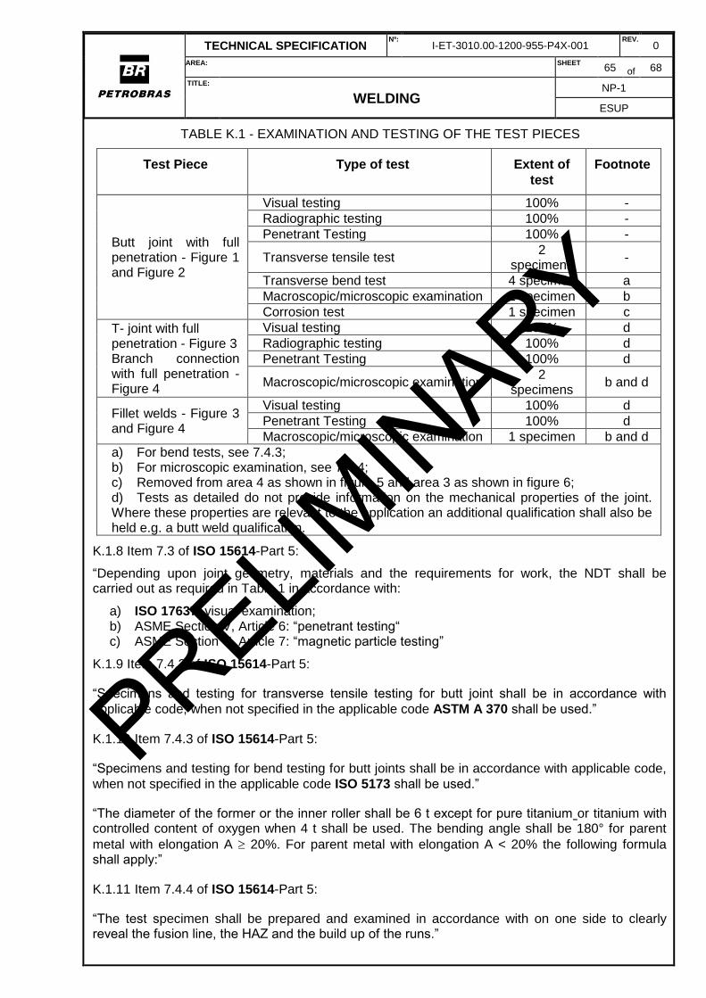
TECHNICAL SPECIFICATION Nº:
I-ET-3010.00-1200-955-P4X-001 REV.
0
AREA: SHEET 65 of 68
TITLE:
WELDING NP-1
ESUP
TABLE K.1 - EXAMINATION AND TESTING OF THE TEST PIECES
Test Piece Type of test Extent of
test
Footnote
Butt joint with full penetration - Figure 1 and Figure 2
Visual testing 100% -
Radiographic testing 100% -
Penetrant Testing 100% -
Transverse tensile test 2
specimens -
Transverse bend test 4 specimen a
Macroscopic/microscopic examination 1 specimen b
Corrosion test 1 specimen c
T- joint with full penetration - Figure 3 Branch connection with full penetration - Figure 4
Visual testing 100% d
Radiographic testing 100% d
Penetrant Testing 100% d
Macroscopic/microscopic examination 2
specimens b and d
Fillet welds - Figure 3 and Figure 4
Visual testing 100% d
Penetrant Testing 100% d
Macroscopic/microscopic examination 1 specimen b and d
a) For bend tests, see 7.4.3; b) For microscopic examination, see 7.4.4; c) Removed from area 4 as shown in figure 5 and area 3 as shown in figure 6; d) Tests as detailed do not provide information on the mechanical properties of the joint. Where these properties are relevant to the application an additional qualification shall also be held e.g. a butt weld qualification.
K.1.8 Item 7.3 of ISO 15614-Part 5:
“Depending upon joint geometry, materials and the requirements for work, the NDT shall be carried out as required in Table 1 in accordance with:
a) ISO 17637: visual examination; b) ASME Section V, Article 6: “penetrant testing“ c) ASME Section V, Article 7: “magnetic particle testing”
K.1.9 Item 7.4.2 of ISO 15614-Part 5:
“Specimens and testing for transverse tensile testing for butt joint shall be in accordance with
applicable code, when not specified in the applicable code ASTM A 370 shall be used.”
K.1.10 Item 7.4.3 of ISO 15614-Part 5:
“Specimens and testing for bend testing for butt joints shall be in accordance with applicable code,
when not specified in the applicable code ISO 5173 shall be used.”
“The diameter of the former or the inner roller shall be 6 t except for pure titanium or titanium with controlled content of oxygen when 4 t shall be used. The bending angle shall be 180° for parent
metal with elongation A 20%. For parent metal with elongation A < 20% the following formula shall apply:”
K.1.11 Item 7.4.4 of ISO 15614-Part 5:
“The test specimen shall be prepared and examined in accordance with on one side to clearly reveal the fusion line, the HAZ and the build up of the runs.”
PRELIMIN
ARY
TECHNICAL SPECIFICATION Nº:
I-ET-3010.00-1200-955-P4X-001 REV.
0
AREA: SHEET 66 of 68
TITLE:
WELDING NP-1
ESUP
K.1.12 Item 7.5 of ISO 15614-Part 5:
“A welding procedure is qualified if the imperfections in the test piece are within the specified limits
of quality level B in ISO 5817 except for imperfection types as follows : excess weld metal, excess convexity, excess throat thickness and excessive penetration, for which quality level C shall apply”.
K.1.13 Item 7.6 of ISO 15614-Part 5:
Accepted colors on the weld metal surface: Bright silver welds are an indication that the weld shielding is satisfactory and that proper weld interpass temperatures have been observed. Light straw-colored weld is acceptable but the discoloration should be removed by wire brushing with a clean stainless steel brush. Darker brown, purple and blue colors and grey or flaky white are not acceptable.
K.2 Hardness Determination
Where ISO 15156 requirements are applicable, maximum hardness levels for parent material, weld metal and weld heat-affected zones are established to secure reliable resistance to stress corrosion cracking (SCC) and sulfide stress cracking (SSC), in H2S-bearing (sour) media. The
hardness location shall be as required by ISO 15156.
Acceptance Criteria:
The hardness limits shall be as required by ISO 15156;
The maximum individual hardness reading on the weld metal shall not exceed more than thirty points on the HV10 Vickers scale than the hardness of parent metal of matching composition.
PRELIMIN
ARY
TECHNICAL SPECIFICATION Nº:
I-ET-3010.00-1200-955-P4X-001 REV.
0
AREA: SHEET 67 of 68
TITLE:
WELDING NP-1
ESUP
ANNEX L (MANDATORY)
L - PASSIVITY TEST FOR NICKEL AND NICKEL ALLOYS
L.1 Scope
L.1.1 This test is intended to reveal the presence of free iron or ferrous oxides on nickel alloy surfaces. Free iron contamination may exist as superficial films or as inclusions.
L.1.2 Two methodologies are accepted to analyze the presence of iron or ferrous oxides on nickel alloy surfaces, as follows.
L.2 TEST PROCEDURE WITH DEMINERALIZED WATER
The surfaces to be tested are sprayed every hour for 12 hours with cold demineralized water without intermediate drying: this time may be reduced to 6 hours if the sprayed drops are sufficiently small to adhere without running down.
A visual examination (using lens with magnification 5 in case of doubt) is performed after the surface is exposed to air for at least 24 hours after water exposure.
L.3 TEST PROCEDURE USING FERROXYL
According to ASTM A 380.
L.4 ACCEPTANCE CRITERIA
The examined surface shall have neither free iron nor iron oxide surface contamination nor iron inclusions or embedded particles.
PRELIMIN
ARY
TECHNICAL SPECIFICATION Nº:
I-ET-3010.00-1200-955-P4X-001 REV.
0
AREA: SHEET 68 of 68
TITLE:
WELDING NP-1
ESUP
ANNEX M (MANDATORY)
M - PROHIBITED AND DETRIMENTAL MATERIALS FOR NICKEL AND NICKEL ALLOYS
M.1 PROHIBITED MATERIALS
M.1.1 Lead, Mercury and other low melting point materials, their alloys and/or their compounds shall not be added to the consumable products as essential chemical constituents.
M.1.2 Sulfur, Lead, low melting point metals, their alloys and their compounds shall be prohibited for use in fabrication, testing, shipping and assembly.
M.2 DETRIMENTAL MATERIALS
A detrimental material is one that can have a deleterious effect on performance if it contacts the hardware. Detrimental materials are classified into seven (07) groups. Each group has allowable maximum concentration limits of detrimental materials in contact with nickel base alloys at each phase of fabrication. Possible sources of detrimental materials are indicated in TABLE M.1.
M.2.1 CONTROLLED PRODUCTS
Controlled products which contain detrimental materials in excess of the concentration limits as shown in TABLE M.1 may be used if at least, one of the following conditions is satisfied:
- No transfer of detrimental material to the parts of the equipment occurs; - Detrimental materials shall be removed later with another accepted product prior next fabrication steps, where control of detrimental material is required; - PETROBRAS has specifically authorized the use of the products.
M.2.2 ACCEPTABLE PRODUCTS
Acceptable products are products listed which satisfy the detrimental material concentrations limits of TABLE M.1.
TABLE M.1 - ACCEPTABLE PRODUCTS.
Detrimental Material
Maximum
Concentration
(ppm)
Possible Sources Stage of
Fabrication
Mercury 0.5 Chemicals Instrumentation Mercury Lighting
All
Lead 0.5 Temperature crayons, hammers, cutting oils, paint, plating, wire brushes
All
Cadmium, Magnesium, Tin, Zinc, Antimony, Arsenic, Bismuth, Silver
10 Hammers, fixtures, lubricants, cutting oils, paint, plating, wire brushes
Final cleaned surfaces or any prior to or during thermal
treatment Aluminum and Copper 250
Soft pads or hammers, probes, tips, copper chill blocks and electrodes for welding
Sulfur 100 Furnace atmosphere, marking materials, lubricants and cutting oils, UT couplants, fluxes Final cleaned
surfaces, prior to or during thermal treatment or machining
Chlorides and Halogens
200 Human perspiration, lubricants, cutting oils, fluxes, penetrant materials, lagging, UT couplants
Phosphorous 250 Furnace atmosphere, marking materials, temperature crayons, lubricants, UT couplant
PRELIMIN
ARY