Embed Size (px)
Citation preview
TECHNICAL SPECIFICATION Nº:
I-ET-3010.1M-1400-140-P4X-002
CLIENT: SUP
SHEET: 1 of 24
JOB: REFERENCE BASIC DESIGN 1001056398 0010
AREA: BÚZIOS
DP&T-SUP
TITLE:
TOPSIDES STRUCTURAL REQUIREMENTS NP-1
ESUP
MICROSOFT WORD / V. 2003 / I-ET-3010.1M-1400-140-P4X-002_0.DOCX
INDEX OF REVISIONS
REV. DESCRIPTION AND/OR REVISED SHEETS
0
ORIGINAL ISSUE
REV. 0 REV. A REV. B REV. C REV. D REV. E REV. F REV. G REV. H
DATE JUL/31/18
DESIGN ESUP
EXECUTION PPASTORE
CHECK NASSUR
APPROVAL JPARREIRA
INFORMATION IN THIS DOCUMENT IS PROPERTY OF PETROBRAS, BEING PROHIBITED OUTSIDE OF THEIR PURPOSE
FORM OWNED TO PETROBRAS N-381 REV. L
PRELIMIN
ARY

TECHNICAL SPECIFICATION Nº: I-ET-3010.1M-1400-140-P4X-002 REV.
0
AREA:
BÚZIOS SHEET:
2 of 24
TITLE:
TOPSIDES STRUCTURAL REQUIREMENTS NP-1
ESUP
SUMMARY
1 INTRODUCTION ................................................................................... 4
2 REFERENCES, CODES, STANDARDS AND PROCEDURES ............ 6
2.1 DESIGN DOCUMENTS ....................................................................................... 6
2.2 RULES, CODES AND STANDARDS .................................................................. 7
3 DESIGN DATA ...................................................................................... 8
3.1 DESIGN LIFE ...................................................................................................... 8
3.2 ENVIRONMENTAL DATA ................................................................................... 8
3.3 STRUCTURAL CATEGORIZATION .................................................................... 8
3.4 UNITS .................................................................................................................. 9
4 MATERIAL ........................................................................................... 10
4.1 STEEL DESIGN PARAMETERS ....................................................................... 10
4.2 MATERIAL THICKNESS ................................................................................... 10
4.3 BOLT MATERIAL .............................................................................................. 10
5 WELDING ............................................................................................ 11
6 INSPECTION ....................................................................................... 11
7 CORROSION CONTROL ................................................................... 11
8 PASSIVE FIRE PROTECTION............................................................ 11
9 STRUCTURAL ANALYSES ................................................................ 12
9.1 SOFTWARES .................................................................................................... 12
9.2 STRUCTURAL MODELING .............................................................................. 12
9.3 LOAD MODELING ............................................................................................ 14
9.4 IN-PLACE ANALYSES ...................................................................................... 17
9.4.1 STATIC CONDITION (SC) ........................................................................ 17
9.4.2 DESIGN OPERATING CONDITION (DOC) .............................................. 17
PRELIMIN
ARY

TECHNICAL SPECIFICATION Nº: I-ET-3010.1M-1400-140-P4X-002 REV.
0
AREA:
BÚZIOS SHEET:
3 of 24
TITLE:
TOPSIDES STRUCTURAL REQUIREMENTS NP-1
ESUP
9.4.3 DESIGN EXTREME CONDITION (DEC) .................................................. 17
9.4.4 DESIGN SERVICEABILITY CONDITION (DSC) ....................................... 18
9.4.5 BLAST ACCIDENTAL CONDITION (BAC) ............................................... 18
9.4.6 DROPPED OBJECT CONDITION ............................................................ 18
9.4.7 VORTEX SHEDDING ............................................................................... 18
9.4.8 DAMAGE CONDITION (DAC) .................................................................. 18
9.4.9 UPLIFT CONDITION (ULC) ...................................................................... 19
9.4.10 HYDROTEST CONDITION (HTC) ............................................................ 19
9.4.11 GREEN WATER CONDITION .................................................................. 19
9.4.12 FATIGUE CONDITION ............................................................................. 19
9.5 INSTALLATION ANALYSES ............................................................................ 20
9.5.1 LIFTING CONDITION (LIC) ...................................................................... 20
9.5.2 DESIGN TRANSIT CONDITIONS (DTC) .................................................. 20
9.5.3 LOAD OUT CONDITION (LOC) ................................................................ 21
9.5.4 SET DOWN (Modules Assembly on Hull) ................................................. 21
10 ACCEPTANCE CRITERIA .................................................................. 21
10.1 GENERAL ......................................................................................................... 21
10.2 PLATE AND STIFFENED PANELS BUCKLING ............................................... 22
10.3 PADEYES .......................................................................................................... 22
10.4 STRUCTURE MAXIMUM DEFLECTIONS CRITERIA ....................................... 22
10.4.1 VERTICAL DEFLECTIONS....................................................................... 22
10.4.2 HORIZONTAL DEFLECTIONS ................................................................. 22
11 GENERATION OF MODULES REACTIONS AT HULL DECK ......... 22
12 EQUIPMENT FOUNDATIONS ............................................................ 23
13 FLARE TOWER, PIPE RACKS AND STRUCTURES ........................ 24
PRELIMIN
ARY

TECHNICAL SPECIFICATION Nº: I-ET-3010.1M-1400-140-P4X-002 REV.
0
AREA:
BÚZIOS SHEET:
4 of 24
TITLE:
TOPSIDES STRUCTURAL REQUIREMENTS NP-1
ESUP
1 INTRODUCTION
This document presents PNBV requirements to be adopted by CONTRACTOR for the structural analysis and design of the topside structures of the PETROBRAS FPSO Units of Reference Project, as part of engineering design development at DETAILING phase. Topside structures comprise, not limited to, topside modules, outfitting, flare tower, pipe-rack structures. Upper riser support structure and pull-in structure are not part of topside Contractor scope of work.
CONTRACTOR refers to DESIGN DETAILING COMPANY in this document.
In addition to PNBV Requirements, CONTRACTOR documents to be delivered to the Classification Society (CS) contracted for the DETAILING phase shall fulfill the additional requirements agreed with this CS.
PETROBRAS FPSO Units may be installed at some Area Development southeastern of Brazilian coast.
CONTRACTOR shall issue a new “Topsides Structural Requirements” document based on the present one, keeping the same philosophy in general, revising and including additional requirements for assembly and construction, detailing the scope of supply, and submit to PNBV for approval.
CONTRACTOR shall fulfill all design requirements specified in this document, but not limited to. Fabrication requirements shall be used by CONTRACTOR as information to guide the design.
CONTRACTOR shall present, for PNBV and CS approval, a detailed Topsides Structural Requirements showing the methodology and computational tools to be adopted. Topsides Structural Requirements carried out during Detailing Phase shall be used as reference, updated and complemented.
All structural design reports and drawings, as well as all computer structural analysis models with loadings (input and output), shall be submitted to PNBV for approval. All structural drawings and design data shall also be submitted in due time for CS approval. CONTRACTOR shall answer CS comments.
This document is complemented by codes, rules and standards presented in Section 2 of this document, subjected to approval of the CS of the Unit.
The latest revision of the Classification Society (CS) requirements shall be used for the design of structures, reinforcements and complementary structures. Additional relevant criteria can be used in the design, based on designer experience and requirements of the CS, since submitted to PNBV and CS for approval.
PRELIMIN
ARY

TECHNICAL SPECIFICATION Nº: I-ET-3010.1M-1400-140-P4X-002 REV.
0
AREA:
BÚZIOS SHEET:
5 of 24
TITLE:
TOPSIDES STRUCTURAL REQUIREMENTS NP-1
ESUP
During DETAILING phase, any change in the FPSO topside main structures and details as well as any change of the design philosophy shall be submitted by CONTRACTOR to PNBV for approval.
By changes one shall understand, for example:
Interference with structures;
Changes of dimensions, cross sections and welds;
Significant changes on weight and general arrangement;
Attachments on structures;
Material changes;
Main non-conformities during detailing, fabrication, assembly and construction phases;
Damages during fabrication and found after the inspections;
Structures out of the specified tolerances, misalignments and deformations above the rules limits;
Changes in Painting Schemes.
Besides those mentioned above, CONTRACTOR shall follow the same procedure for any other relevant modification or change.
The International System of Units (SI) shall be used in the analyses, reports and drawings.
All 2-D and 3-D drawings shall be provided in system formats compatible with the contractual software.
PRELIMIN
ARY

TECHNICAL SPECIFICATION Nº: I-ET-3010.1M-1400-140-P4X-002 REV.
0
AREA:
BÚZIOS SHEET:
6 of 24
TITLE:
TOPSIDES STRUCTURAL REQUIREMENTS NP-1
ESUP
2 REFERENCES, CODES, STANDARDS AND PROCEDURES
2.1 DESIGN DOCUMENTS
All documents listed in I-LD-3010.1M-1200-940-P4X-002 shall be used as reference, with emphasis on the following:
[1] I-DE-3010.1M-1200-942-P4X-002 – GENERAL ARRANGEMENT;
[2] I-LI-3010.1M-1200-940-P4X-002 – EQUIPMENT LIST;
[3] I-RL-3010.1M-1350-960-P4X-009 – MOTION ANALYSIS;
[4] RL-3010.1M-1350-960-P4X-001 – ANÁLISE DOS ÂNGULOS MÁXIMOS DE BANDA E TRIM;
[5] I-ET-3A26.00-1000-941-PPC-001 – METOCEAN DATA;
[6] I-DE-3010.1M-1400-140-P4X-002 – GENERAL NOTES FOR TOPSIDES STRUCTURES;
[7] I-ET-3010.00-1200-956-P4X-006 – GENERAL PAINTING;
[8] I-ET-3010.1M-5266-630-P4X-001 – TOPSIDE'S MECHANICAL HANDLING PROCEDURES;
[9] I-ET-3010.00-1200-251-P4X-001 – BOLT MATERIALS;
[10] I-RL-3010.1M-5400-947-P4X-001 – EXPLOSION ANALYSIS;
[11] I-RL-3010.1M-1351-140-P4X-001 – HULL GLOBAL DEFLECTION;
[12] I-ET-3010.00-1400-140-P4X-002 – GUIDELINE FOR DROPPED OBJECT STRUCTURE ANALYSIS.
PRELIMIN
ARY

TECHNICAL SPECIFICATION Nº: I-ET-3010.1M-1400-140-P4X-002 REV.
0
AREA:
BÚZIOS SHEET:
7 of 24
TITLE:
TOPSIDES STRUCTURAL REQUIREMENTS NP-1
ESUP
2.2 RULES, CODES AND STANDARDS
Rules, codes and standards from the list below shall be employed for structural design of the hull structure and attached structures, subjected to CS approval. Latest edition of each one shall be used, or, otherwise, contractual applicable edition, when specified. Rules, codes and standards other than those shall be submitted to PNBV and CS for approval.
[13] AISC 335-89 – Specification For Structural Steel Building – Allowable Stress Design and Plastic Design, 9th Ed.;
[14] API RP 2A – WSD – 23st Ed. – Recommended Practices for Planning, Designing and Constructing Fixed Offshore Structures – Working Stress Design – Errata and Supplement 3, Oct. 2007;
[15] ISO / CD 19901-3 – Specific Requirements for Offshore Structures ;
[16] DnV RP C201 – Buckling Strength of Plated Structures ;
[17] DnVGL RP C205 – Environmental Conditions and Environmental Loadings;
[18] DnVGL RP C203 – Fatigue Design of Offshore Steel Structures;
[19] DnVGL OS C102 – Structural Design of Offshore Ships;
[20] API Standard 537 – 2nd. Edition – Flare Details for General Refinery and Petrochemical Service;
[21] NORSOK N-003 – Actions and Actions Effects;
[22] DnV CN 30.7 – Fatigue Assessment of Ship Structures;
[23] ABS – Floating Production Installations Guide;
[24] ABS – Rules for Materials and Welding (Part2);
[25] ABS – Rules for Building and Classing Offshore Installations;
[26] DNVGL-OS-C201 – Structural Design of Offshore Units (WSD Method);
[27] DNVGL-RP-C102 – Structural Analysis of Ship Structures;
[28] NORSOK Standard M-101 – Structural Steel Fabrication;
[29] Research Council on Structural Connections (RCSC) – Specification for Structural Joints Using High Strength Bolts, 2009;
[30] DNVGL-ST-N001 – Marine Operations and Marine Warranty;
[31] MODU CODE 2010;
[32] Text of the Resolutions Adopted by the 22nd General Conference on Weights and Measures – 2003.
PRELIMIN
ARY

TECHNICAL SPECIFICATION Nº: I-ET-3010.1M-1400-140-P4X-002 REV.
0
AREA:
BÚZIOS SHEET:
8 of 24
TITLE:
TOPSIDES STRUCTURAL REQUIREMENTS NP-1
ESUP
3 DESIGN DATA
3.1 DESIGN LIFE
The Units shall be designed for 25 years minimum operation period without docking.
3.2 ENVIRONMENTAL DATA
Environmental parameters for in-place analyses and for transportation analyses shall be obtained from Metocean Data [5].
3.3 STRUCTURAL CATEGORIZATION
All areas of the structures shall be categorized according to the application and consequence of failure.
Table 1 – Structural Categorization
A Special Design Area
Those regions of the Primary Structure that are critical for the load transfer, and may be subject to critical stress concentrations. Examples for process plant modules are: module foundations, crane pedestal foundations, lifting padeyes and members attached to module supports at padeyes regions.
B Primary Design Area
Structural elements essential to the overall unit integrity, but less critical than the Special Design Area. This class is represented in process plant modules by main girders, columns and diagonals, heavy equipment supports, deck plates and bulkheads that provide global resistance for module.
C Secondary Design
Area
Structural elements of minor importance, the failure of which is unlikely to affect the unit integrity. This class is represented in process plant modules by deck plates, stiffeners and bulkheads that are not taking part on global resistance, and piping supports.
D
Tertiary Design Area
Structural elements of minor importance, the failure of with is unlikely to affect the unit integrity. This class is represented in process plant modules by stairs, walk ways, handrails and others.
Further details can be found in General Notes for Topside Structures [6].
PRELIMIN
ARY

TECHNICAL SPECIFICATION Nº: I-ET-3010.1M-1400-140-P4X-002 REV.
0
AREA:
BÚZIOS SHEET:
9 of 24
TITLE:
TOPSIDES STRUCTURAL REQUIREMENTS NP-1
ESUP
3.4 UNITS
International System of Units (S.I.) metric system shall be used throughout the project, including input data and results of numerical analyses, quantitative information released in calculation notes, drawings or any other document. The following units shall be used as standard units on the project:
Table 2 – Standard Units on the Project
Description or structural characteristic Unit
Member length, joint coordinates, etc.
m
Tube diameter and wall thickness, section prismatic properties, deflections, etc.
mm or cm
Angles deg
Forces kN
Moments kN.m
Distributed loads kN/m² or kN/m
Masses kg or
metric tons (t)
Member stress N/mm² (MPa)
Time s (second)
Wind velocities m/s
Accelerations m/s²
Temperature °C
The numerical notation adopted in all documents shall be as recommended in the 22nd General Conference on Weights and Measures [32] and presented below:
- The symbol for the decimal marker shall be dot ".";
- Numbers shall be divided in groups of three in order to facilitate reading; neither dots nor commas are ever inserted in the spaces between groups.
PRELIMIN
ARY

TECHNICAL SPECIFICATION Nº: I-ET-3010.1M-1400-140-P4X-002 REV.
0
AREA:
BÚZIOS SHEET:
10 of 24
TITLE:
TOPSIDES STRUCTURAL REQUIREMENTS NP-1
ESUP
4 MATERIAL
Material grades shall be in accordance with the requirements of the Classification Society of the Unit for topside structures. Grade selection shall take into account the plate thickness, the structural categorization and design temperature. Details on material grades can be found in General Notes for Topsides Structures [6].
4.1 STEEL DESIGN PARAMETERS
Steel design properties will be taken as:
Young's Modulus → E = 20 600.00 kN/cm²
Shear Modulus → G = 7 920.00 kN/cm²
Poisson's Ratio → = 0.30
Density → = 7 850.00 kg/m³
Coefficient of thermal expansion → = 12.0 x 10⁻⁶/ºC
Steel design temperature: 0º
Creep curves and heat effects need to be assessed for special application (e.g.: flare tower).
With the use of a heat shield to protect the flare tower structure, expected levels of temperature shall be below 350 °C.
4.2 MATERIAL THICKNESS
The range of plate thicknesses and beam and pipe sizes shall take into account simplification of material supply and utilization as well as low expenditures.
To prevent laminar tearing, steel with ‘Z’ quality (through thickness strength) shall be used in locations with significant through thickness stress. The significant through thickness stress shall be considered as σt ≥ 0.3Fy.
4.3 BOLT MATERIAL
Structural joints shall be welded. Bolted joints may be used for hook-up parts and removable parts only. Bolt material for structural elements shall be specified according to [9].
PRELIMIN
ARY

TECHNICAL SPECIFICATION Nº: I-ET-3010.1M-1400-140-P4X-002 REV.
0
AREA:
BÚZIOS SHEET:
11 of 24
TITLE:
TOPSIDES STRUCTURAL REQUIREMENTS NP-1
ESUP
Material to be: - Bolts ASTM A325/A325M or ASTM A490/A490M, Nuts ASTM A563/A563M, Washers ASTM F436/F436M - where neither high pressure nor high temperature is an issue. Requirements in the respective standards to be complied with and corresponding certified reports of required tests to be presented (*); - Bolts ASTM A193/A193M Grade B16, Nuts ASTM A194 Grade 7 (see ref. [9]) - where high pressure and/or high temperature is an issue. Coating System to be: 8-12%Ni balanced Zn coating, for temperature less than 150 oC (see ref. [9]). Threads shall be rolled type.
(*) Guidance for definition of joint type, installation requirements, such as possible requirement for specification of a minimum pretension, and other requirements, to be taken from [29].
5 WELDING
Welds shall be properly dimensioned for all design conditions. In addition, minimum requirements shall be used according to General Notes for Topsides Structures [6].
6 INSPECTION
Welds NDT extension shall be in accordance with General Notes for Topside Structures [6].
7 CORROSION CONTROL
The topside structures shall be adequately corrosion protected by the coating system in accordance with General Painting [7]. No corrosion allowance needs to be considered for topside structures.
8 PASSIVE FIRE PROTECTION
Based on special Safety Study results, the topside structures shall be adequately protected by a passive fire protection in order to prevent the spread of fire and the exposure of adjacent equipment to thermal radiation.
PRELIMIN
ARY

TECHNICAL SPECIFICATION Nº: I-ET-3010.1M-1400-140-P4X-002 REV.
0
AREA:
BÚZIOS SHEET:
12 of 24
TITLE:
TOPSIDES STRUCTURAL REQUIREMENTS NP-1
ESUP
9 STRUCTURAL ANALYSES
This section describes the design analyses to be performed during DETAILING phase.
The CONTRACTOR shall design the topside structures according to CS Rules and PNBV requirements.
9.1 SOFTWARES
The following softwares are acceptable for structural analysis.
For modules, flare tower and other frame structures:
GTStrudl;
SESAM/GENIE;
SACS;
SAP.
For other structures:
SESAM;
ANSYS;
FEMAP.
Other structural software shall be submitted to PETROBRAS for approval.
9.2 STRUCTURAL MODELING
A tri-dimensional space frame model shall be elaborated with unidirectional members (bars). The working points of the main elements (columns, beams and braces) shall be at the unique center of a frame joint according the Figure 1, therefore there are no eccentricities in the structural model. CONTRACTOR shall not change the working point locations of the Basic Design unless submitted and approved by PNBV.
PRELIMIN
ARY

TECHNICAL SPECIFICATION Nº: I-ET-3010.1M-1400-140-P4X-002 REV.
0
AREA:
BÚZIOS SHEET:
13 of 24
TITLE:
TOPSIDES STRUCTURAL REQUIREMENTS NP-1
ESUP
Figure 1 – Unifilar Model Typical
Deck floor is modelled with FEM elements - membrane type – connected at the working points in order to give lateral bracing to the whole model. Elements with rigid offset shall not be used. Member and joint checks shall use forces and moments taken at working points. The concept of connections of module structures to hull shall be:
Module supported on columns attached to the upper deck by means of gusset plates. These gusset plates are directed in transverse ship direction and are in line with under deck transverse web frame or transverse bulkheads. The function of the transverse gusset plates is to act as hinges, minimizing stress in the module structure due to hull girder bending under wave loads and loading/unloading of the FPSO, which generates strain in the upper deck and make the bottom connection of the columns displace in longitudinal direction.
In longitudinal direction, braces are applied in central bay (one web frame space), so between two columns in longitudinal direction. At these locations, gusset plates are installed at vessel upper deck also in the longitudinal directions and in line with the ship’s longitudinal stiffeners, in order to avoid punching of the upper deck plating.
Besides bracing in longitudinal direction, braces are also required in transverse direction.
For module support columns mentioned above, the following boundary conditions shall be applied to the FEM model.
PRELIMIN
ARY
TECHNICAL SPECIFICATION Nº: I-ET-3010.1M-1400-140-P4X-002 REV.
0
AREA:
BÚZIOS SHEET:
14 of 24
TITLE:
TOPSIDES STRUCTURAL REQUIREMENTS NP-1
ESUP
All supports are restrained for translation in X, Y and Z direction.
All elements braced with gusset plates shall have gusset in-plane rotations restrained and gusset out-of-plane rotations released.
Stress concentration factors and other local effects are evaluated by means of plates and bi-dimensional FEM elements. For fatigue analysis of the end of gusset plate between column and hull deck, FEM models with shell type elements shall be executed. Mesh size shall be of the order of plate thickness at peak stress locations for hot spot stress derivation. For yielding verification, mesh size shall not be greater than 50 mm at these locations, with limiting stresses according to CS Rules.
The flare tip and the flare headers for gas flow may be modelled as beam elements not for structural verifications but for the correct transference of loads from the piping lines to the flare tower structure.
Package structure of CO2 Removal module M-04 shall be included in the structural models of this module.
Additional auxiliary structures for equipment support and electrical equipment room as well as walkway for maintenance and access shall be included in the structural model of Power Generation modules M-12 and M-13.
The CO2 Removal and Power Generation modules M-04, M-12 and M-13 package structures shall be included in the modules structural models, including all packages loads as dead weight, live loads, equipment weight, inertial loads, wind loads. Structural verification of modules shall be performed using this complete model.
Process pipe rack shall be include the starboard modules structure and its loads, including dead weights, live loads, inertial loads, piping weights and hull deflections. Module structure verification shall be performed using this complete model.
9.3 LOAD MODELING
Heavy equipment loads shall be applied on the model so that correct inertial loading due to vessel motions and correct COG position are represented and reactions are properly transferred to main structure, such as by using fictitious elements.
The remaining equipment may be considered as bulks and applied as distributed loads over the appropriate areas.
The gross dead weight of modeled structure shall be generated directly from the structural model adopted on the analysis. The gross dead weight of not modeled secondary steelwork (such as secondary beams, gratings, ladders, stairs, handrails, walkways, maintenance platforms and equipment supports) shall be input as uniformly distributed or concentrated loads. All gross weights shall be taken from the latest revision of the Weight Control Report.
PRELIMIN
ARY

TECHNICAL SPECIFICATION Nº: I-ET-3010.1M-1400-140-P4X-002 REV.
0
AREA:
BÚZIOS SHEET:
15 of 24
TITLE:
TOPSIDES STRUCTURAL REQUIREMENTS NP-1
ESUP
Live load on deck area shall be applied in accordance with the Table 3, that shall be considered as PETROBRAS minimum requirements:
Table 3 – Functional Load on Deck Area
Distributed Load Point Load Distributed Load Distributed Load
kN/m2 kN (note 4) kN/m2 kN/m2
AREA
Load Design
(note 1)
Primary Design
(note 2)
Global Design
(note 3)
VARIABLE FUNCTIONAL LOADS ON DECK AREAS OF TOPSIDE STRUCTURES
may be ignored
Storage
40Lay-down
Free area between equipment
15 15 15 15
3 3 3
9 may be ignored may be ignored
may be ignored7.5 may be ignored
q = max (g.H; 13)
Walkways, staircases and
platforms
Walkways and staircases for
inspection only and scape routes
4
5
may be ignored
30
q
5
Storage room, workshop and
maintenance areas
Process (note 5)
Utilities (note 5)
9
7.5
40
4 may be ignored
Roof 2.5 2.5 2.5 may be ignored
1.5q q
30
may be ignored5
γ = specific weight of storage material; H= storage height; q = max (γ.H; 13)
(1) Load Design is used in the local analysis of plates and beams;
(2) Primary Design is used in the structural design of the primary and secondary structures;
(3) Global Design is used in the structural design of foundations;
(4) Point loads may be applied on an area 100 x 100 mm, and at the most severe position, but not added to wheel loads or distributed loads;
(5) The variable functional loads shall not be applied at free area between equipment and maintenance areas for the DEC and Fatigue Conditions;
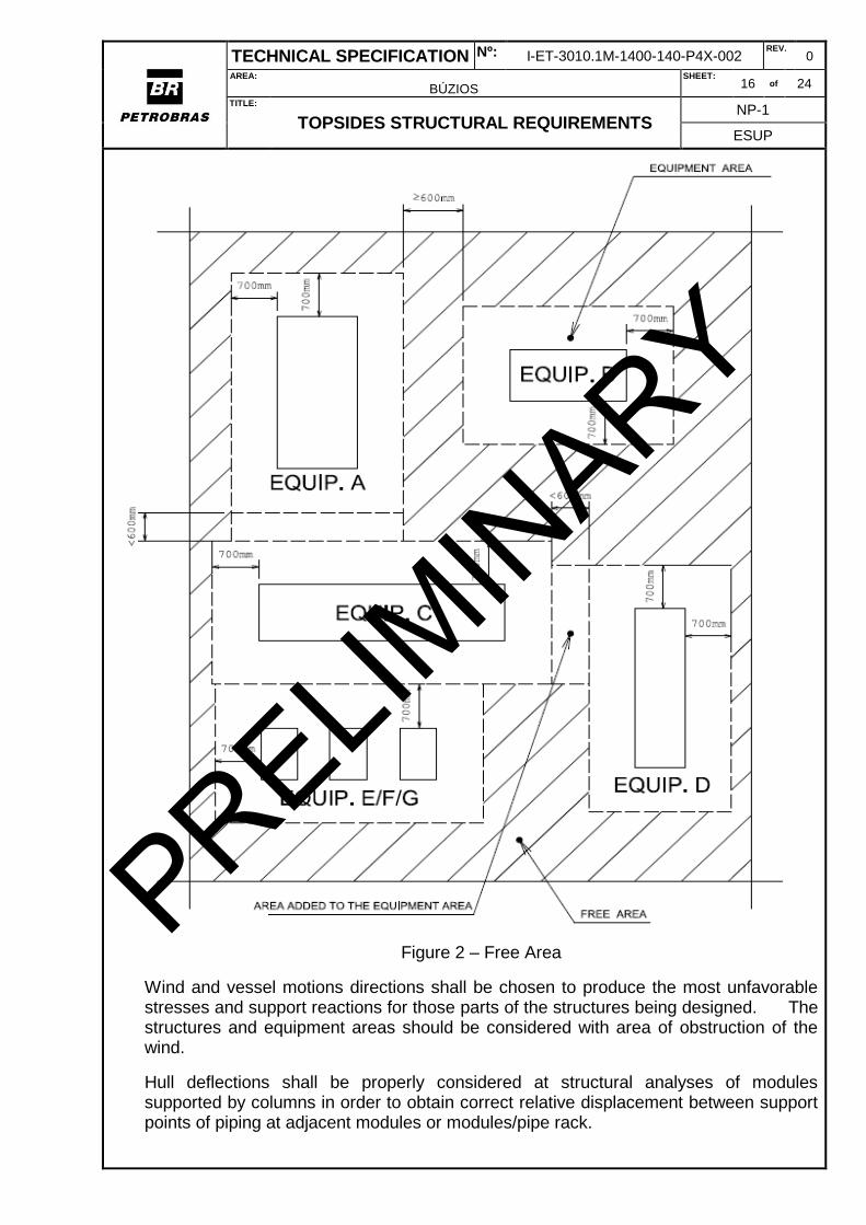
(6) For equipment loads, the worst case between the table above or the equipment weight plus structural dead weight and plus 5.00 kN/m2 applied over a free surrounding area shall be considered;
(7) See Figure 2 below.
PRELIMIN
ARY
TECHNICAL SPECIFICATION Nº: I-ET-3010.1M-1400-140-P4X-002 REV.
0
AREA:
BÚZIOS SHEET:
16 of 24
TITLE:
TOPSIDES STRUCTURAL REQUIREMENTS NP-1
ESUP
Figure 2 – Free Area
Wind and vessel motions directions shall be chosen to produce the most unfavorable stresses and support reactions for those parts of the structures being designed. The structures and equipment areas should be considered with area of obstruction of the wind.
Hull deflections shall be properly considered at structural analyses of modules supported by columns in order to obtain correct relative displacement between support points of piping at adjacent modules or modules/pipe rack.
PRELIMIN
ARY

TECHNICAL SPECIFICATION Nº: I-ET-3010.1M-1400-140-P4X-002 REV.
0
AREA:
BÚZIOS SHEET:
17 of 24
TITLE:
TOPSIDES STRUCTURAL REQUIREMENTS NP-1
ESUP
Structural analyses of other structures connected to the hull main deck shall include hull deflections [11]
Inertial loading shall be calculated using accelerations from [3] according to the following procedure:
- For head seas conditions maximum longitudinal accelerations shall be used with associated transversal and vertical accelerations;
- For beam seas conditions maximum transversal accelerations shall be used with associated longitudinal and vertical accelerations;
- For oblique conditions, longitudinal accelerations shall be taken as (the maximum longitudinal acceleration * 0.707), transversal acceleration shall be taken as (the maximum transversal acceleration * 0.707). Maximum vertical acceleration shall be used.
9.4 IN-PLACE ANALYSES
The in-place analyses shall include the following design conditions:
9.4.1 STATIC CONDITION (SC)
Just dead weights (structural, equipment, piping, electrical and instrumentation weights) and live loads shall be considered. Hull deflections, wind and wave loads shall not be considered. This condition shall be used only for monorails verification.
No increase in allowable stresses is permitted.
9.4.2 DESIGN OPERATING CONDITION (DOC)
The design operation condition (DOC) refers to the structure under 1-year return period motions accelerations and wind. Structural dead weights, live loads, equipment loads, moving loads such as self-propelled rail car and crane loads, piping weight and horizontal piping loads (when designing pipe rack), electrical and instrumentation weights, hull deflections, wind pressures and accelerations due to vessel motion shall be considered.
No increase in allowable stresses is permitted.
9.4.3 DESIGN EXTREME CONDITION (DEC)
The design extreme condition (DEC) refers to structure under 100-year return period motions accelerations and wind. Structural dead weights, live loads, equipment loads, piping weight and horizontal piping loads (when designing pipe rack), electrical and instrumentation weights, hull deflection, wind pressures and accelerations due to vessel motion shall be considered.
Use of one-third increase in allowable stresses is permitted.
PRELIMIN
ARY

TECHNICAL SPECIFICATION Nº: I-ET-3010.1M-1400-140-P4X-002 REV.
0
AREA:
BÚZIOS SHEET:
18 of 24
TITLE:
TOPSIDES STRUCTURAL REQUIREMENTS NP-1
ESUP
9.4.4 DESIGN SERVICEABILITY CONDITION (DSC)
This condition shall be used to verify the deflections of the structure. Dead weights in operation, live loads, with DOC wind and DOC wave loads shall be considered.
No increase in allowable stresses is permitted.
9.4.5 BLAST ACCIDENTAL CONDITION (BAC)
Blast pressures resulting from explosion which may occur inside a module, below a module or outside a module shall be considered. Blast resisting walls and modules main structure shall be designed to withstand pseudo-static blast pressure.
Use of two-third increase in allowable stresses is permitted.
9.4.6 DROPPED OBJECT CONDITION
Dropped object verification shall be done according to [12].
9.4.7 VORTEX SHEDDING
This analysis aims to verify vortex shedding effects caused by the wind in the structure. To avoid resonance due to vortex shedding, the structural tubular members shall be verified using the procedures presented in DNVGL RP-C205 [17].
No increase in allowable stresses is permitted.
9.4.8 DAMAGE CONDITION (DAC)
This condition refers to the structure verification for an accidental event or operation. Damage condition shall be verified using the procedures presented in DNVGL-OS-C102 [19]. The structural design for damage condition shall be performed for the following scenarios:
1 - Unintended flooding shall be based on the deepest equilibrium waterline in damaged condition obtained from damage stability report. Association with 1-year motions and accelerations DAC analysis shall be performed consider.
DAC analysis shall be performed considering the following damage angles obtained from [4].
- Heel: X.XX° (Hold)
- Trim: X.XX° (Hold)
2 – Static cases according to [31]:
- Static Heel Angle: 22.5°
- Static Trim Angle: 10.0°
Above Heel and Trim angle shall be applied separately, i.e., 2 different loading conditions shall be considered, one for the heel angle and another for the trim angle.
PRELIMIN
ARY

TECHNICAL SPECIFICATION Nº: I-ET-3010.1M-1400-140-P4X-002 REV.
0
AREA:
BÚZIOS SHEET:
19 of 24
TITLE:
TOPSIDES STRUCTURAL REQUIREMENTS NP-1
ESUP
9.4.9 UPLIFT CONDITION (ULC)
Uplift condition is used to verify the trend of the structure to fall over, as well as to calculate minimum reactions (possible occurrence of tension) at columns bases.
9.4.10 HYDROTEST CONDITION (HTC)
All structures shall be verified for hydrotest condition (HTC) before being lifted, transported and installed onto the FPSO and after installation, during platform operation. Only structural dead weights, equipment test weight, piping test weight and electrical and instrumentation weights shall be considered during this condition. No live loads nor environmental loads shall be considered.
No increase in allowable stresses is permitted.
9.4.11 GREEN WATER CONDITION
Green water verification shall be done according to [3]. A distributed hydrostatic pressure combined with all loads considered in Operation and Extreme Condition.
Use of one third increase in allowable stress is permitted.
9.4.12 FATIGUE CONDITION
MODULES STRUCTURES, PIPE RACK
For modules, pipe rack and main deck structures, fatigue analysis shall be performed. The simplified approach may be used as presented in section 5 of DnVGL RP-C203 – Fatigue Strength Analysis of Offshore Steel Structures [18] , considering a 25 years design life.
If any reinforcement is required based on simplified fatigue analysis, a full stochastic analysis shall be performed in order to avoid local fatigue reinforcements.
For the simplified analysis, loading and stress variation shall be obtained from in-place analysis. S-N curves and stress concentration factors (SCF) shall be assumed based on DnVGL RP-C203 [18] recommendation.
The Weibull parameter h may be obtained from CS rules or based on a specific calibration submitted to PNBV and C.S. approval.
Target fatigue life shall be in accordance with the next table.
Table 4 - Target Fatigue Life
Structural Components Safety Factor Target Fatigue Life (years)
Secondary Structure Joints 1.0 25
Primary Structure Joints 2.0 50
Module / Hull Connections 2.0 50
Module/ Hull Connections Non Inspectonable Parts
10.0 250
PRELIMIN
ARY

TECHNICAL SPECIFICATION Nº: I-ET-3010.1M-1400-140-P4X-002 REV.
0
AREA:
BÚZIOS SHEET:
20 of 24
TITLE:
TOPSIDES STRUCTURAL REQUIREMENTS NP-1
ESUP
FLARE TOWER STRUCTURE
For flare tower the fatigue life of the main structure shall be determined using a Spectral Fatigue Analysis approach.
The same 25 years design life shall be considered with safety according to table 9.2 above.
Flare tower fatigue calculation shall consider the damage due to wind gustiness and the damage due to vessel motions. Total fatigue life shall be determined by their combination according to DnV CN 30.7 [22].
9.5 INSTALLATION ANALYSES
This section describes the installation design analyses to be performed during DETAILING phase.
Installation analyses shall include the following design conditions:
9.5.1 LIFTING CONDITION (LIC)
Lifting analyses shall be carried out according to DNVGL – ST – N001 [30].
The model COG shall be monitored and aligned with the project Weight Report. During DETAILING phase acceptable limits of deviations shall be defined above which actions deemed necessary shall be taken.
Design of guides and bumpers shall follow DNVGL – ST – N001 [30] or equivalent. Modules columns and other members chosen to support guides and bumpers shall be temporarily braced accordingly.
No increase in allowable stresses is permitted.
9.5.2 DESIGN TRANSIT CONDITIONS (DTC)
For modules structures, Design Transit Condition shall be verified in the design life for two different phases:
- Transit from the construction site to the shipyard on a transport barge - (DTC 1);
- Transit of the FPSO from the shipyard to the installation site, with all structures installed onto – (DTC 2).
Flare tower structure shall be verified only for transit of the FPSO from the shipyard to the installation site, with all structures installed onto – (DTC 2).
Use of one-third increase in allowable stresses is permitted.
For Design Transit Conditions (DTC), fatigue analysis shall be evaluated.
PRELIMIN
ARY

TECHNICAL SPECIFICATION Nº: I-ET-3010.1M-1400-140-P4X-002 REV.
0
AREA:
BÚZIOS SHEET:
21 of 24
TITLE:
TOPSIDES STRUCTURAL REQUIREMENTS NP-1
ESUP
9.5.3 LOAD OUT CONDITION (LOC)
To cover the load out condition a maximum 25mm vertical deflection of one support of the module shall be considered combined with the dead loads and empty equipment.
The limiting value defined above is the maximum allowed misalignment between the barge and shore skid ways and shall be confirmed by Contractor based on the load out procedure to be developed.
The values and conditions shall be confirmed during DETAILING phase, according to the load out procedure to be adopted and to recommendations from C.S. and NORSOK STANDARD M-101 [28] .
No increase in allowable stresses is permitted.
9.5.4 SET DOWN (Modules Assembly on Hull)
Contractor shall employ an appropriate procedure that assures misalignments and mismatches are within limits assumed in the design premises. It is assumed that all support points to main module beams (top of columns and diagonals) are leveled to a level of tolerance such that the main module beams are expected to touch all those points at set down operation. If it is anticipated during DETAILING phase that this condition will not be completely reached, additional structural analyses shall be carried out to evaluate the effects of settlement on specific members of the structure and eventual solutions, keeping the same general philosophy. Special devices and installation procedures shall be considered in order to mitigate misalignments and mismatch effects.
The construction tolerances for the Support Points of the Topsides Structures are defined in GENERAL NOTES FOR TOPSIDES STRUCTURES [6].
10 ACCEPTANCE CRITERIA
10.1 GENERAL
In general, the structures are designed such that all the structural members are proportioned for the permissible allowable stresses as specified by AISC 335 - 89 - 9th Ed. and API RP 2A-WSD – 23st Edition. For the Design Extreme Condition the AISC/API RP2A basic allowable stresses may be increased by 1/3. For the Blast Condition the AISC/API RP2A basic allowable stresses may be increased by 1.80, which represents maximum stress equal to 1.2Fy.
PRELIMIN
ARY

TECHNICAL SPECIFICATION Nº: I-ET-3010.1M-1400-140-P4X-002 REV.
0
AREA:
BÚZIOS SHEET:
22 of 24
TITLE:
TOPSIDES STRUCTURAL REQUIREMENTS NP-1
ESUP
10.2 PLATE AND STIFFENED PANELS BUCKLING
Plate buckling shall be checked in accordance with DNV RP-C201 [16].
10.3 PADEYES
The following allowable stresses shall be used for the design of padeyes. Tension/Compression 0.60Fy In-Plane Bending 0.66Fy Out of Plane Bending 0.75Fy Shear 0.40Fy Bearing 0.90Fy In addition, design factors are applied according to DNVGL – ST – N001 [30] recommendation.
10.4 STRUCTURE MAXIMUM DEFLECTIONS CRITERIA
10.4.1 VERTICAL DEFLECTIONS
- Girder deflections are verified in according with AISC [13] (item 1.3). - They are limited to L/360 for primary structure, where L is the girder span.
10.4.2 HORIZONTAL DEFLECTIONS
- Horizontal deflections are verified in according with item 6.5.3 of ISO 19901-3 [15]. - For module columns, horizontal deflections shall generally be limited to 0.3% of the height between floors. - For multi-floors modules, the total horizontal deflection shall not exceed 0.2% of the total height of the topside structure. OBS: If horizontal deflection criteria is not complied with, structures designer shall verify with piping designer if the deflections are acceptable.
11 GENERATION OF MODULES REACTIONS AT HULL DECK
For yielding and buckling analyses of the hull in way of modules column foundations, CONTRACTOR shall create a table at the respective module calculation report, containing all the reactions for all loadings in the point P0, according to Figure 3. At the beginning of this table, it shall be described the envelope of maximum forces for the analyses above mentioned.
PRELIMIN
ARY

TECHNICAL SPECIFICATION Nº: I-ET-3010.1M-1400-140-P4X-002 REV.
0
AREA:
BÚZIOS SHEET:
23 of 24
TITLE:
TOPSIDES STRUCTURAL REQUIREMENTS NP-1
ESUP
Figure 3 – Typical Section
For peak stress yielding and fatigue analysis of the hull under the gusset plate weld toe, CONTRACTOR shall create a table at the respective module calculation report containing all the reactions for all loadings at the points P1 and P2 according to Figure 3 above. At the beginning of this table, it shall be described the envelope of maximum dynamic reactions for the analyses before mentioned. The reactions shall be according to the global axis: X = Vessel longitudinal direction, positive from stern to bow Y = Vessel transversal direction, positive from starboard to portside Z = Vessel vertical direction, positive upwards Structural and loading modeling, including boundary conditions, shall keep the same design criteria adopted for module structural analysis, according to Sections 10.2, 10.3 and 10.4. The reactions at point P1 and P2 shall be obtained from this model using sectional forces command at the structural program. The following eight directions shall be adopted: 00, 450, 900, 1350, 1800, 2250, 2700, 3150. Directions 00 and 1800 shall be associated with head sea accelerations, 900 and 2700 directions with beam sea accelerations, the remaining directions with quartering seas accelerations. The fatigue loads (maximum dynamic reactions) are obtained as the difference between 100-years (storm condition) loads of opposite directions, totaling four directions.
12 EQUIPMENT FOUNDATIONS
Besides normal verification, all equipment support shall be verified for the maximum heeling and trim, as well as the extreme loading, as specified on MOTION ANALYSIS [3] and the values defined in the CS Rules.
Functional loads, test loads, equipment vibrations and environmental loads shall be taken into account. Anti-vibration mountings consisting of rubber and metal shall be installed when structural behavior or acceptance levels for personnel demands.
PRELIMIN
ARY
TECHNICAL SPECIFICATION Nº: I-ET-3010.1M-1400-140-P4X-002 REV.
0
AREA:
BÚZIOS SHEET:
24 of 24
TITLE:
TOPSIDES STRUCTURAL REQUIREMENTS NP-1
ESUP
Every equipment foundation shall have its own weight evaluated for weight control procedure.
It is Contractor responsibility to supply and install any wedge or plate needed to level the equipment skids to be installed directly over the ship and modules decks.
13 FLARE TOWER, PIPE RACKS AND STRUCTURES
These structures, including the necessary supports and hull structural reinforcements, must be evaluated in all design conditions, including the Unit’s transport from shipyard to location.
The structural analysis must consider the Unit’s motions, accelerations and wind loads.
For flare tower, the horizontal lifting and the upending shall be considered. The entire flare tower, including empty equipment and piping, shall be lifted from the quayside or transport barge and installed onto Units by means of an inshore lift.
For the flare tower structures, the structural analysis must also consider thermal loads.
Temperature gradients on flare tip and through tower length must be taken from a Flare Radiation Report in order to confirm the dimensions of the heat shield.
The concept of the bracing system shall be revised during DETAILING phase, aiming at improved distribution of foundation reactions.
PRELIMIN
ARY
![[MatErial codE standards] - BRELECT · [MatErial codE standards] Material codes and names and their respective naming rules are managed in accordance with the prescribed standards](https://img.pdfslide.us/doc/110x75/5bfa875b09d3f24c058c838f/material-code-standards-material-code-standards-material-codes-and-names.jpg)