Embed Size (px)
Citation preview
RPT-190
Independent Investigation Report of the November 2005 Drum Fire at the Idaho National Laboratory Site
March 2006
RPT-190
Independent Investigation Report of the November 2005 Drum Fire at theIdaho National Laboratory Site
March 2006
Idaho Cleanup Project Radioactive Waste Management Complex
Idaho Falls, Idaho 83415
Prepared for the U.S. Department of Energy
Assistant Secretary for Environmental Management Under DOE Idaho Operations Office
Contract DE-AC07-05ID14516
iii
EXECUTIVE SUMMARY
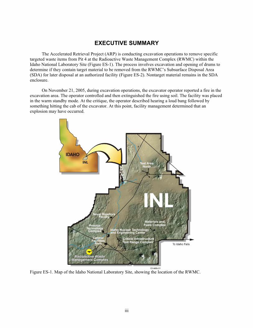
The Accelerated Retrieval Project (ARP) is conducting excavation operations to remove specific
targeted waste items from Pit 4 at the Radioactive Waste Management Complex (RWMC) within the
Idaho National Laboratory Site (Figure ES-1). The process involves excavation and opening of drums to
determine if they contain target material to be removed from the RWMC’s Subsurface Disposal Area
(SDA) for later disposal at an authorized facility (Figure ES-2). Nontarget material remains in the SDA
enclosure.
On November 21, 2005, during excavation operations, the excavator operator reported a fire in the
excavation area. The operator controlled and then extinguished the fire using soil. The facility was placed
in the warm standby mode. At the critique, the operator described hearing a loud bang followed by
something hitting the cab of the excavator. At this point, facility management determined that an
explosion may have occurred.
Figure ES-1. Map of the Idaho National Laboratory Site, showing the location of the RWMC.
iv
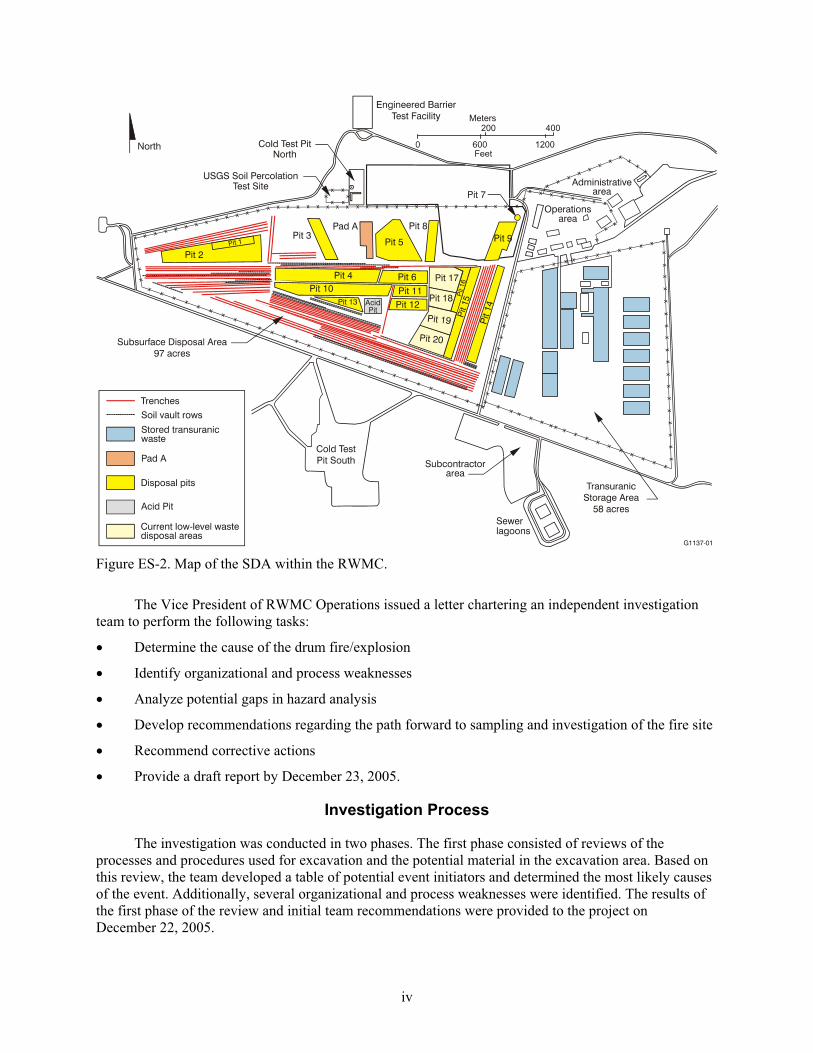
Figure ES-2. Map of the SDA within the RWMC.
The Vice President of RWMC Operations issued a letter chartering an independent investigation
team to perform the following tasks:
Determine the cause of the drum fire/explosion
Identify organizational and process weaknesses
Analyze potential gaps in hazard analysis
Develop recommendations regarding the path forward to sampling and investigation of the fire site
Recommend corrective actions
Provide a draft report by December 23, 2005.
Investigation Process
The investigation was conducted in two phases. The first phase consisted of reviews of the
processes and procedures used for excavation and the potential material in the excavation area. Based on
this review, the team developed a table of potential event initiators and determined the most likely causes
of the event. Additionally, several organizational and process weaknesses were identified. The results of
the first phase of the review and initial team recommendations were provided to the project on
December 22, 2005.
v
The second phase of the investigation consisted of examining the event scene and sampling the
contents of the drum that was the source of the event. The fieldwork for the second phase was completed
on February 14, 2006. The final laboratory results from the samples were received on February 23, 2006.
Event Site Investigation
The two drums suspected to be involved in the event were found immediately next to each other.
The drum that was the source of the fire was found with its lid and ring in place. The drum had several
openings in it that are consistent with being squeezed and vented by the excavator. There was no visual
external evidence of an explosion. The drum contained an inner drum (30-gal) whose lid was still in
place. The inner drum was positioned near the top of the outer drum. The inner-drum lid was found to be
mostly intact. The inner drum lid had a hole in it that appeared to be consistent in size and location to
have been caused by the excavator during the venting process. The inner-drum lid had visual evidence of
being involved in a fire and contained numerous smaller holes that appeared to have been caused by the
fire. There was some combustion residue and other debris on the top of the inner drum lid. There was no
evidence of an explosion from the inner drum.
The inner drum was opened and found to contain a black granular/powdery material that was
sampled and confirmed to be depleted uranium (roaster oxide).
The drum that was next to the event drum had no visual evidence of being involved in the fire. The
lid of this drum was found partially open, consistent with being squeezed by the excavator during venting.
Plastic liner material was visible in the opening. This material displayed no evidence of melting or
discoloration from a fire.
Conclusion
Based on the evidence available, the following is the most likely scenario: During the process of
venting the drum, the inner drum was also punctured. Oxygen introduction into the inner drum caused a
rapid oxidation reaction that released hydrogen from uranium hydride and resulted in a fire. It is likely
that hydrogen and volatile organic compounds contributed fuel to the fire. The fire rapidly expelled the
majority of the material in the area above the inner drum and some of this material hit the excavator cab.
It is also likely that the visible flames were created from several openings around the top of the drum.
After the initial fire was extinguished, the uranium continued to oxidize under the soil. The adjacent drum
was not involved as source of fuel for the fire. There is no physical evidence that an explosion occurred.
Neither drum shows deformations (i.e., outward bulging areas) consistent with those expected from an
explosion.
Event Cause
The cause of the event was the excavation and venting of roaster oxide (i.e., depleted uranium) that
was packaged and buried in a partially or incompletely oxidized condition. It is likely that this fire would
have occurred when the inner drum was vented either during the excavation process or during the
subsequent sampling campaign being planned for roaster oxide drums.
Organizational and Process Weaknesses
The team reviewed the excavation process and procedures and identified organizational and
process weaknesses. The more significant weaknesses involved failure to follow procedural requirements,
lack of needed detail in the operational procedures, and a deficient Management Self Assessment for start
vi
of operations after contract transition. These weaknesses did not contribute to nor were they identified as
causal factors for the fire.
Hazard Analysis Weaknesses
The team reviewed the existing hazards analysis documents. The set of hazards analysis documents
for the project were found to be deficient. The Safety Analysis Report was weak, specifically in the area
of worker protection. The fire hazards assessment states that there is little evidence that the pyrophoric
metals buried in the excavation area are in a form that either will spontaneously ignite or be easily ignited
and self-sustaining. The Health and Safety Plan did not recognize the potential for explosions or missile
hazards and consequently did not contain any controls. Specific issues with the safety analysis documents
are included in the body of the report. These weaknesses did not contribute to nor were they identified as
causal factors for the fire.
Implications
The weaknesses identified by the team were in all areas of the Integrated Safety Management
System. In several cases, hazards introduced by process changes were not identified; consequently, they
were not analyzed and no controls were implemented. Although few, the team identified instances where
specific controls in procedures were not being followed. Additionally, several prior events involving
roaster oxides and some chronic equipment problems were not identified as needing more review,
analysis, and corrective actions, indicating a weakness in the effectiveness of the feedback and
improvement process.
Recommended Corrective Actions
The detailed recommendations are contained in the body of the report. They address concerns in
the following major areas.
Based on the material being excavated, it is likely that similar events will occur in the future. Plan
the work activities assuming that a similar event could occur. The planning should include controls
for fires, deflagrations, and the potential for projectiles.
Establish and reinforce management’s expectations for the conduct of work including formality of
operations and use of the feedback and improvement process.
Conduct additional reviews of the hazards and controls for the work being performed. Implement
the results of these reviews in the project’s hazards analysis documents.
Improve the content, clarity, and scope of the project procedures.
vii
CONTENTS
EXECUTIVE SUMMARY ......................................................................................................................... iii
ACRONYMS............................................................................................................................................... xi
1. BACKGROUND................................................................................................................................ 1
1.1 Project Description ................................................................................................................ 3
1.2 Process Description ............................................................................................................... 4
1.3 ARP Safety Support Systems ................................................................................................ 5
1.3.1 ARP Fire Protection ............................................................................................ 5
1.3.2 Excavator and Telehandler Forced-Air Ventilation Systems.............................. 6
1.4 Pit 4 Waste Descriptions ....................................................................................................... 7
1.4.1 Description of Waste in the Pit ........................................................................... 8
1.4.2 Description of Waste in I-2 ............................................................................... 10
2. INVESTIGATION SCOPE, PURPOSE, AND METHODOLOGY................................................ 11
3. DESCRIPTION OF EVENT............................................................................................................ 12
3.1 Operator Description of the Event....................................................................................... 12
3.2 Additional Information from the Evidence Available ......................................................... 12
4. SCENE INVESTIGATION.............................................................................................................. 14
4.1 Phase 1 Initial Sampling...................................................................................................... 14
4.2 Phase 2 Sampling of Drum Contents................................................................................... 15
5. DETERMINATION OF THE CAUSE OF THE FIRE.................................................................... 21
5.1 Sampling Logic ................................................................................................................... 21
5.1.1 Potential Scenario Analysis............................................................................... 21
5.2 Sample Results .................................................................................................................... 25
5.3 Depleted Uranium Oxidation Process and Fire History ...................................................... 27
5.4 Likely Fire Initiation Scenario............................................................................................. 28
5.5 Cause ................................................................................................................................... 28
6. IDENTIFICATION OF ORGANIZATION AND PROCESS WEAKNESSES ............................. 31
viii
6.1 Evaluation of Project Emergency Response Actions .......................................................... 31
6.2 Project Safety and Hazards Analysis................................................................................... 32
6.2.1 Safety Analysis Report Weaknesses ................................................................. 32
6.2.2 Fire Protection................................................................................................... 33
6.2.3 Health and Safety Plan Weaknesses.................................................................. 35
6.3 Use of Timely Orders .......................................................................................................... 36
6.4 Procedure Inadequacies ....................................................................................................... 36
6.5 Project History and Potential Significant Events Identified by the Investigation Team ..... 36
6.5.1 Timeline Analysis ............................................................................................. 36
6.6 Accelerated Retrieval Project Process Weakness Cause and Effect Diagram..................... 41
7. PROCESS AND ORGANIZATIONAL WEAKNESS INTEGRATED SAFETY MANAGEMENT
SYSTEM RELATIONSHIP AND RECOMMENDATIONS.......................................................... 42
7.1 Additional Recommendations ............................................................................................. 45
7.2 Fire Fighting Recommendations ......................................................................................... 45
8. REFERENCES................................................................................................................................. 46
9. DOCUMENTS REVIEWED ........................................................................................................... 47
FIGURES
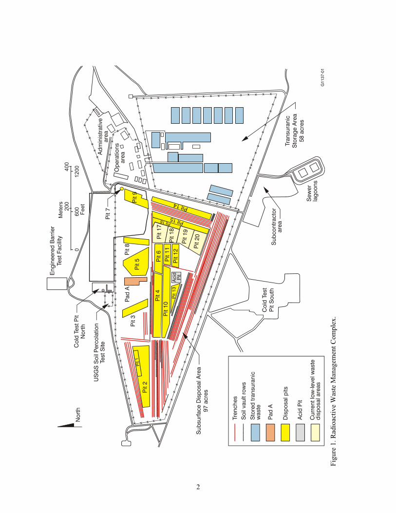
1. Radioactive Waste Management Complex........................................................................................ 2
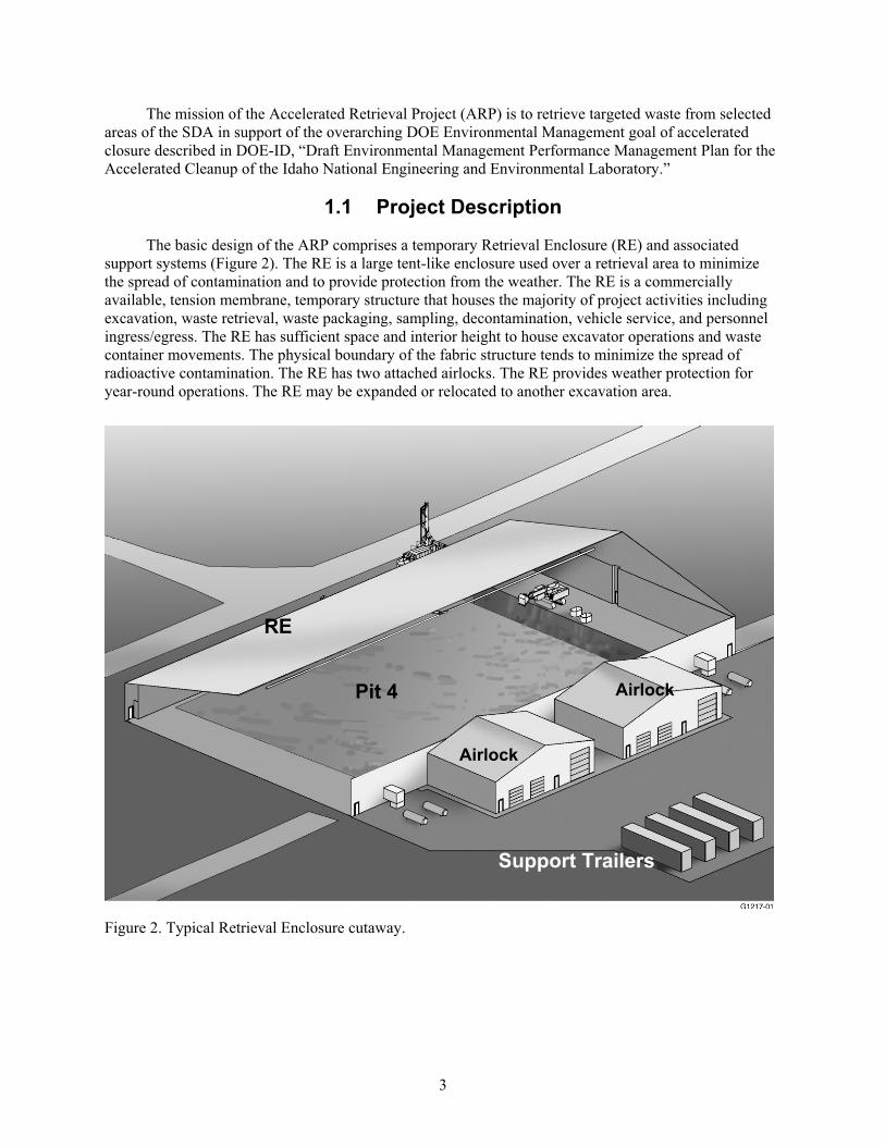
2. Typical Retrieval Enclosure cutaway. ............................................................................................... 3
3. Subsurface Disposal Area, with Pit 4 in the center. .......................................................................... 7
4. ARP Retrieval Area. .......................................................................................................................... 8
5. Grid of retrieval area inside the ARP Retrieval Enclosure (each grid is approximately
15 ft 15 ft)..................................................................................................................................... 10
6. Smoke coming from fire after initial extinguishing effort............................................................... 13
7. Photo of initial excavation showing what was suspected as the corroded drum top and ring. ........ 14
8. Photo of excavation of drum continued, showing top lid and ring.................................................. 15
9. Photo of event drum exposed. ......................................................................................................... 16
ix
10. Photo of excavation of drum continued, showing top of the drum charred and pitted.................... 16
11. Photo showing black granular/powder removed from 30-gal drum. ............................................... 17
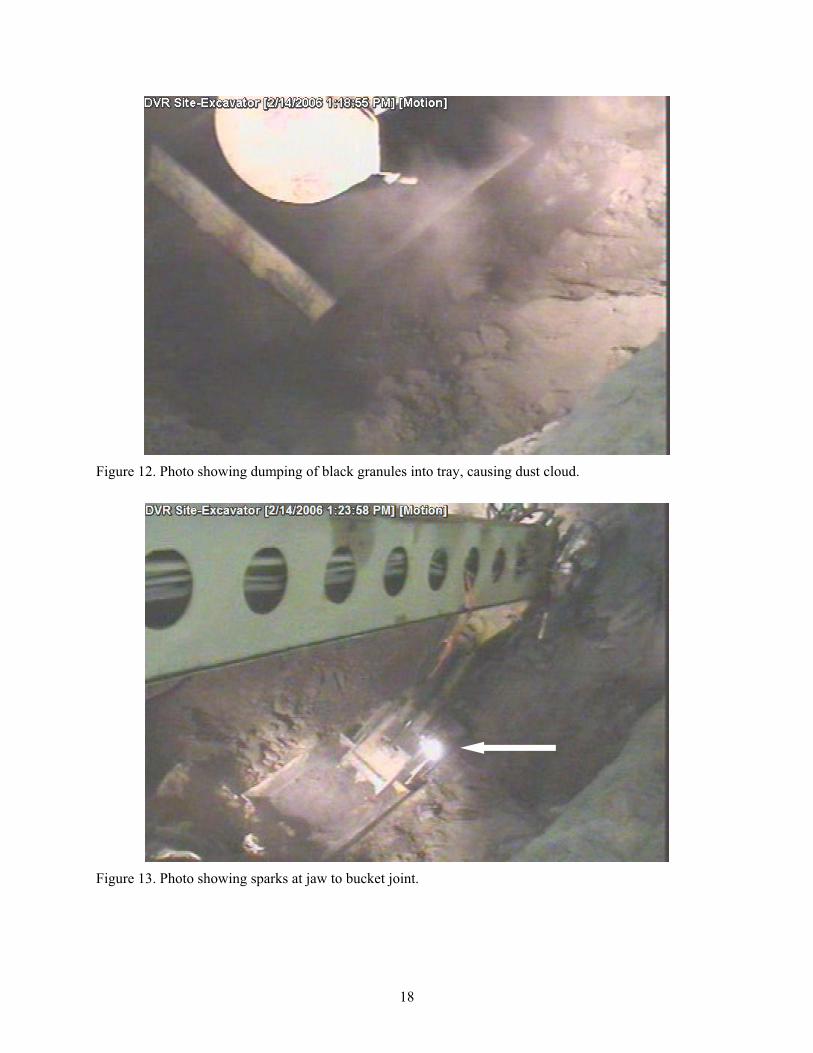
12. Photo showing dumping of black granules into tray, causing dust cloud........................................ 18
13. Photo showing sparks at jaw to bucket joint. .................................................................................. 18
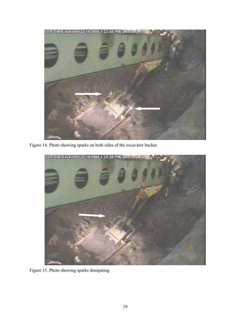
14. Photo showing sparks on both sides of the excavator bucket.......................................................... 19
15. Photo showing sparks dissipating.................................................................................................... 19
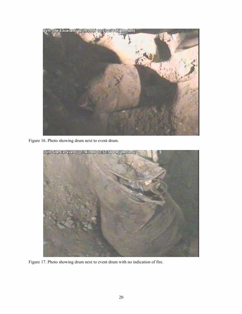
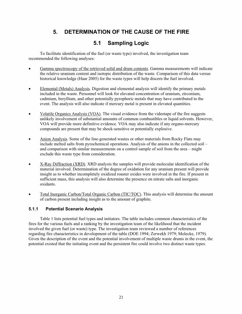
16. Photo showing drum next to event drum......................................................................................... 20
17. Photo showing drum next to event drum with no indication of fire. ............................................... 20
18. Events and conditions summary of the Accelerated Retrieval Project drum event......................... 29
19. Timeline of pre-fire events. ............................................................................................................. 38
20. Timeline of post-fire events............................................................................................................. 39
21. Accelerated Retrieval Project process weakness cause and effect diagram. ................................... 41
TABLES
1. Fire scenario analysis. ..................................................................................................................... 22
2. Uranium analyses of samples. ......................................................................................................... 25
3. Organic analyses for samples. ......................................................................................................... 26
4. Barrier analysis of ARP drum event................................................................................................ 30
5. Process and organizational weakness Integrated Safety Management System relationship and
recommendations............................................................................................................................. 42

x
xi
ACRONYMS
AEC Atomic Energy Commission
AK acceptable knowledge
ARP Accelerated Retrieval Project
BBWI Bechtel BWXT Idaho, LLC
CERCLA Comprehensive Environmental Response, Compensation, and Liability Act
CFR Code of Federal Regulations
CWI CH2M-WG Idaho, LLC
DiD Defense in Depth
DOE U.S. Department of Energy
DOE-ID U.S. Department of Energy Idaho Operations Office
DPS drum packaging station
EAR emergency, abnormal operating, and alarm response (procedure)
EDF engineering design file
EDMS Electronic Document Management System
EG evaluation guideline
EPA U.S. Environmental Protection Agency
FHA fire hazards analysis
HEPA high-efficiency particulate air
ICP Idaho Cleanup Project
INL Idaho National Laboratory
MSA management self-assessment
NFPA National Fire Protection Association
RE retrieval enclosure
RFP Rocky Flats Plant
RO roaster oxide
RWMC Radioactive Waste Management Complex
SDA Subsurface Disposal Area
SSCs structure, system, or component
TIC thermal imaging camera
TIC/TOC total inorganic carbon/total organic carbon
TRU transuranic (waste)
TSA Transuranic Storage Area
USGS United States Geological Survey
xii
USQ Unreviewed Safety Question
VE visual examination
VOA volatile organics analysis
VOC volatile organic compound
WC water column
WILD Waste Information and Location Database
WIPP Waste Isolation Pilot Plant
XRD x-ray diffraction
1
Independent Investigation Report of the November 2005 Drum Fire at theIdaho National Laboratory Site
1. BACKGROUND
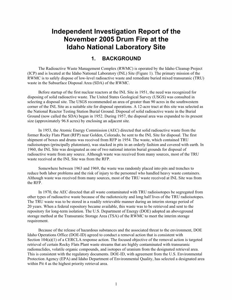
The Radioactive Waste Management Complex (RWMC) is operated by the Idaho Cleanup Project
(ICP) and is located at the Idaho National Laboratory (INL) Site (Figure 1). The primary mission of the
RWMC is to safely dispose of low-level radioactive waste and remediate buried mixed transuranic (TRU)
waste in the Subsurface Disposal Area (SDA) of the RWMC.
Before startup of the first nuclear reactors at the INL Site in 1951, the need was recognized for
disposing of solid radioactive waste. The United States Geological Survey (USGS) was consulted in
selecting a disposal site. The USGS recommended an area of greater than 90 acres in the southwestern
corner of the INL Site as a suitable site for disposal operations. A 12-acre tract at this site was selected as
the National Reactor Testing Station Burial Ground. Disposal of solid radioactive waste in the Burial
Ground (now called the SDA) began in 1952. During 1957, the disposal area was expanded to its present
size (approximately 96.8 acres) by enclosing an adjacent site.
In 1953, the Atomic Energy Commission (AEC) directed that solid radioactive waste from the
former Rocky Flats Plant (RFP) near Golden, Colorado, be sent to the INL Site for disposal. The first
shipment of boxes and drums was received from RFP in 1954. The waste, which contained TRU
radioisotopes (principally plutonium), was stacked in pits in an orderly fashion and covered with earth. In
1960, the INL Site was designated as one of two national interim burial grounds for disposal of
radioactive waste from any source. Although waste was received from many sources, most of the TRU
waste received at the INL Site was from the RFP.
Somewhere between 1963 and 1969, the waste was randomly placed into pits and trenches to
reduce both labor problems and the risk of injury to the personnel who handled heavy waste containers.
Although waste was received from many sources, most of the TRU waste received at INL Site was from
the RFP.
In 1970, the AEC directed that all waste contaminated with TRU radioisotopes be segregated from
other types of radioactive waste because of the radiotoxicity and long half lives of the TRU radioisotopes.
The TRU waste was to be stored in a readily retrievable manner during an interim storage period of
20 years. When a federal repository became available, this waste was to be retrieved and sent to the
repository for long-term isolation. The U.S. Department of Energy (DOE) adopted an aboveground
storage method at the Transuranic Storage Area (TSA) of the RWMC to meet the interim storage
requirement.
Because of the release of hazardous substances and the associated threat to the environment, DOE
Idaho Operations Office (DOE-ID) agreed to conduct a removal action that is consistent with
Section 104(a)(1) of a CERCLA response action. The focused objective of the removal action is targeted
retrieval of certain Rocky Flats Plant waste streams that are highly contaminated with transuranic
radionuclides, volatile organic compounds, and isotopes of uranium from the designated retrieval area.
This is consistent with the regulatory documents. DOE-ID, with agreement from the U.S. Environmental
Protection Agency (EPA) and Idaho Department of Environmental Quality, has selected a designated area
within Pit 4 as the highest priority retrieval area.
2
Fig
ure
1.
Rad
ioac
tiv
e W
aste
Man
agem
ent
Co
mp
lex
.
3
The mission of the Accelerated Retrieval Project (ARP) is to retrieve targeted waste from selected
areas of the SDA in support of the overarching DOE Environmental Management goal of accelerated
closure described in DOE-ID, “Draft Environmental Management Performance Management Plan for the
Accelerated Cleanup of the Idaho National Engineering and Environmental Laboratory.”
1.1 Project Description
The basic design of the ARP comprises a temporary Retrieval Enclosure (RE) and associated
support systems (Figure 2). The RE is a large tent-like enclosure used over a retrieval area to minimize
the spread of contamination and to provide protection from the weather. The RE is a commercially
available, tension membrane, temporary structure that houses the majority of project activities including
excavation, waste retrieval, waste packaging, sampling, decontamination, vehicle service, and personnel
ingress/egress. The RE has sufficient space and interior height to house excavator operations and waste
container movements. The physical boundary of the fabric structure tends to minimize the spread of
radioactive contamination. The RE has two attached airlocks. The RE provides weather protection for
year-round operations. The RE may be expanded or relocated to another excavation area.
RRRE
Figure 2. Typical Retrieval Enclosure cutaway.
Support Trailers
RE
Airlock
AirlockPit 4
4
Project activities consist of retrieving targeted waste from the SDA using an excavator. An
excavator retrieves the waste from the SDA pit and places it in a transfer tray; a telehandler forklift
transports the loaded transfer tray to a drum packaging station (DPS). The waste is then visually
examined to verify conformance to WIPP waste acceptance requirements, packaged in clean 55-gal
drums, and placed in interim storage awaiting further characterization or final disposition.
High-efficiency particulate air (HEPA)-filtered exhaust ventilation is provided for the RE. The
exhaust inlets are located to draw air from the least contaminated areas into the most potentially-
contaminated areas. An exhaust stack of sufficient height to ensure local worker safety and proper
emissions monitoring configuration is provided. The ventilation system has emissions monitoring to
sample and record possible releases of radioactive substances.
The vehicle cabs for excavators and telehandler are pressurized with a blower/HEPA- filtered,
forced air ventilation system to provide protection for the operator. The cabs are not designed to be
contamination free; therefore, vehicle operators wear protective clothing and respiratory protection to
protect them from radioactive material contamination and chemical exposure hazards. The vehicle cabs
are decontaminated as necessary to ensure that the goals to keep radiological contamination as low as
reasonably achievable are met.
The only personnel with access to the RE during excavation activities are the operators working
inside the cabs of the excavator and telehandler. Personnel with access to the retrieval area during other
activities are protected with the appropriate level of personal protective equipment (PPE) and monitoring.
Access is controlled by the Radiation Protection and Industrial Hygiene programs.
1.2 Process Description
Excavation was started in a designated area of Pit 4. REs are constructed and relocated to other
SDA pits as necessary. Soil overburden may be removed and stored for pit backfill. Based on visual
examination, waste-zone materials are segregated into two waste groups: a targeted waste group and a
nontargeted waste group. Targeted waste is repackaged into 55-gal drums and nontargeted waste is
returned to the pit. The nontargeted waste consists of items such as combustibles, scrap metals, interstitial
soil, and miscellaneous sludges. Targeted waste is contaminated with volatile organic compounds
(VOCs), various isotopes of uranium, and TRU radionuclides. It consists of graphite, filter media,
uranium roaster oxides, and Series 741 and 743 sludges. The excavator operator places nontargeted waste
into soft-sided containers that are staged outside of the pit or relocates nontargeted waste within the pit to
allow access to targeted waste. If an operator determines that waste at the excavation is nontargeted, it is
not retrieved. As room becomes available in the excavation pit due to the removal of targeted waste, the
excavator operators return the staged nontargeted waste containers to the pit using the appropriate
excavator end effector. As excavation progresses, the pit is backfilled with nontargeted waste, potentially
contaminated soil, previously removed overburden, or clean soil brought into the RE from outside. At the
end of the excavation campaign, the pit is covered with enough clean overburden soil to prevent the
spread of contamination.
As the waste is excavated, the excavator operator watches for intact drums. If an intact drum of
targeted waste is found, the excavator pierces and depressurizes it with spikes (thumbs) located on the
bucket to release potential hydrogen that may have accumulated in the drum. The excavator then places
the drum or loose waste materials on a waste transfer tray for transport to the DPS. Waste may also be
staged outside the pit (aboveground) until it can be processed.
Technicians at the DPSs open the vented drums and internal containers, if necessary, using electric
and pneumatic hand tools and select screening samples from the potentially targeted waste. The screening
5
technicians use visual assessment, gross alpha/beta swipes, direct low-energy gamma detectors, and/or
organic vapor analysis to identify targeted waste. If the technicians determine that the waste is targeted,
then they assign the applicable shipping codes, collect physical samples to meet shipping requirements,
and remove any Waste Isolation Pilot Plant (WIPP) prohibited items. WIPP-prohibited items are either
returned to the pit or containerized for further processing. Transfer trays with nontargeted waste are
returned to the pit are to allow content removal.
Excavation activities can generate dust and increase airborne and surface contamination levels. To
minimize the spread of contamination, the excavator operator sprays water onto the digface during
excavation. The excavator boom is equipped with two nozzles for applying the spray. HEPA filter
equipped air movers, positioned adjacent to the transfer tray, control dust during transfer to the transfer
tray, mitigating airborne radioactivity.
Waste packaging is performed at DPSs. Transfer trays lined with a nylon tray liner and loaded with
targeted waste are brought to a DPS via telehandler. Some nontargeted waste and underburden soil may
also be brought to a DPS for random sampling. The telehandler sets the transfer tray on a trolley, and the
trolley runs into the packaging station, using a pneumatic ram. The waste in the transfer trays is
monitored for radiation levels as the trays are loaded into the DPSs or inside the DPSs. Waste technicians
at the DPSs screen the package contents using portable instrumentation and monitor drum fill weights as
they load the containers.
The excavator and telehandler used for waste retrieval in the RE are commercially available
vehicles that have been modified for the project. The most significant modifications include installation of
a breathing-air system; a HEPA filtered and forced-air ventilation system, fire suppression system (for the
engine), and an excavator dust suppression system. The units are diesel-powered with 86-gal and 41-gal
tanks, respectively. A fuel-catch tray has been installed on the excavator to reduce the chances of a
possible pit fire from a fuel tank leaking into the open pit.
1.3 ARP Safety Support Systems
The ARP safety support systems include fire protection systems (detection and suppression), the
excavator and telehandler safety features, and the breathing air system.
1.3.1 ARP Fire Protection
The SDA is not provided with a fixed water distribution system. The nearest fire hydrant is located
1,500 ft from the ARP site, at the west edge of the RWMC operations area. Water for any extended
suppression efforts will be supplied by the fire department through an extended large diameter hose lay.
To provide the minimum required water supply, a trailer is provided with 3,000 ft of pre-connected
4-in.-diameter hose used to reach the RE. An additional 400 ft of 4 in. hose and 500 gallons of water are
available from the fire department engine.
To supplement the available water supply, a 4,000-gal firewater storage tank is installed near the
RE. The water tank is equipped with an isolation valve and a 4-in. standardized connection to allow
prompt connection to the fire department water tender or engine pump inlet.
1.3.1.1 Fire Detection and Alarm Systems. The RE is provided with smoke detection and a
building fire alarm and occupant notification system to notify occupants and the fire department in case of
emergency. The system includes manual-pull stations at each exit and occupant notification devices.
Additionally, telephones are provided and some operations personnel are equipped with two-way radios
6
to notify the shift supervisor and to communicate with the fire department in case of a fire or other
emergency during operations.
For the RE, occupancy provides an effective detection means when the building is occupied, and is
relied on as the primary detection method during operating periods. A fire watch is instituted when the
area is unattended and the periodicity of observation is specified in operating procedures. The fire watch
may be a roving fire watch or be provided via a camera-based system covering the RE. The camera-based
system consists of web cameras monitored by the INL Fire Alarm Center on dedicated monitors installed
at CFA-666. Web cameras are installed on opposite walls of the RE, and one in each room of the airlocks.
Additionally, thermal-imaging cameras that cover the excavation area are also provided. While the web
cameras have a fixed field of view, the thermal-imaging cameras have limited pan, tilt, and zoom to allow
them to focus on the immediate excavation area. While the thermal-imaging cameras are installed to
provide adequate coverage of the excavation as it progresses, only a single camera is in use at any time
when required for fire watch. As part of the approved fire protection exemption, a high-sensitivity smoke
detection system has been provided to the RE. The high-sensitivity smoke detection system is employed
in conjunction with the fire-watch cameras during nonoperating periods only to avoid false alarms from
suspended dust that accompanies the excavation.
1.3.1.2 Fire Suppression Systems. The RE has no fixed, building fire suppression system
because of the temporary nature and low combustible loading of the structure. As part of the approved fire
protection exemption for the RE, several local-application fire protection features have been provided to
aid in incipient-stage fire suppression. These include an automatic dry chemical suppression system on
the excavators and telehandler, automatic and manual dry chemical suppression systems for the drum
packaging stations, and traditional portable fire extinguishers.
The drum packaging station fire suppression systems are designed and installed to control Class A,
B, and C fires that originate within the drum packaging stations without the use of water. Based on the
area of each drum packaging station, only a single nozzle discharging within the station is required. A
second nozzle and additional dry chemical agent ensure proper operation without regard to placement of
the bag hoist, a potential discharge obstruction, the drum packaging station openings, or drum packaging
station ventilation. Each suppression-agent release panel is provided with a local alarm and is connected
to the building alarm panel. Discharge, whether initiated by automatic, manual pull, or direct manual
activation, activates building alarms and reports to the INL Fire Alarm Center.
The excavators and telehandler engine compartments are equipped with onboard, commercially-
available, automatic, dry-chemical fire suppression systems. The systems are capable of automatic
detection and actuation and remote manual actuation. The dry chemical is discharged through fixed
nozzles into the protected areas, suppressing the fire. When the system is activated, an interlock shuts
down the vehicle diesel engine.
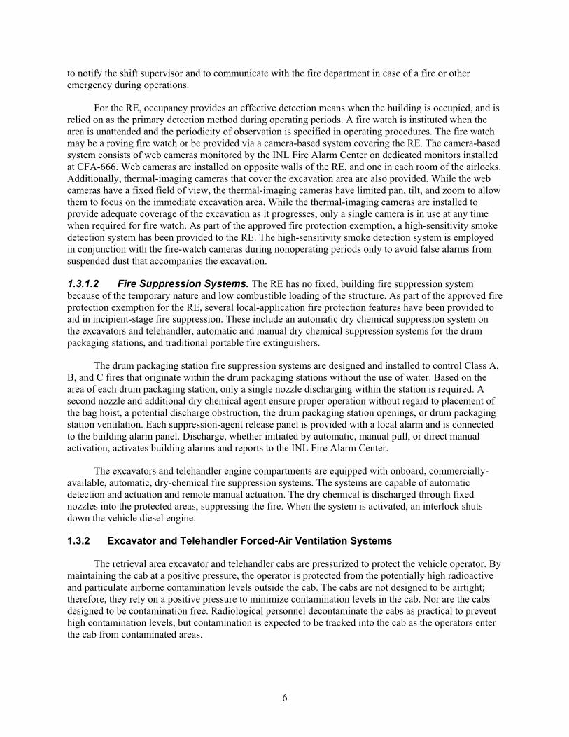
1.3.2 Excavator and Telehandler Forced-Air Ventilation Systems
The retrieval area excavator and telehandler cabs are pressurized to protect the vehicle operator. By
maintaining the cab at a positive pressure, the operator is protected from the potentially high radioactive
and particulate airborne contamination levels outside the cab. The cabs are not designed to be airtight;
therefore, they rely on a positive pressure to minimize contamination levels in the cab. Nor are the cabs
designed to be contamination free. Radiological personnel decontaminate the cabs as practical to prevent
high contamination levels, but contamination is expected to be tracked into the cab as the operators enter
the cab from contaminated areas.
7
Each vehicle is equipped with a radial blower to pressurize the cab. The airflow is from outside the
cab, through a prefilter, through the fan, and through two parallel, double-stage, nuclear-grade HEPA
filters before pressurizing the cab. Differential pressure gauges are installed to measure the pressure drop
across the HEPA filters. These gauges are used for indication of HEPA filter performance. The cabs are
designed to operate at or above 0.75 in. water column (WC). An alarm system notifies the operator in the
event of low differential pressure in the cab. The alarm is set to actuate when cab pressure is less than or
equal to 0.45 in. WC and provides the operator with both a visual and audible indication.
1.4 Pit 4 Waste Descriptions
The RWMC is located at the INL Site, which is a DOE facility located 52 km (32 mi) west of
Idaho Falls, Idaho. The INL Site occupies 2,305 km2 (890 mi2) of the northeastern portion of the Eastern
Idaho Snake River Plain. The RWMC is located in the southwestern portion of the INL Site. The SDA
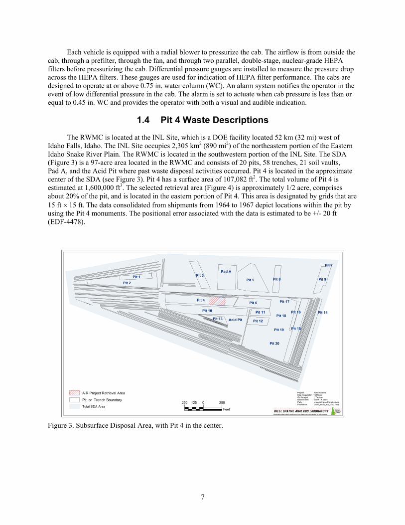
(Figure 3) is a 97-acre area located in the RWMC and consists of 20 pits, 58 trenches, 21 soil vaults,
Pad A, and the Acid Pit where past waste disposal activities occurred. Pit 4 is located in the approximate
center of the SDA (see Figure 3). Pit 4 has a surface area of 107,082 ft2. The total volume of Pit 4 is
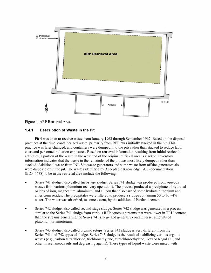
estimated at 1,600,000 ft3. The selected retrieval area (Figure 4) is approximately 1/2 acre, comprises
about 20% of the pit, and is located in the eastern portion of Pit 4. This area is designated by grids that are
15 ft 15 ft. The data consolidated from shipments from 1964 to 1967 depict locations within the pit by
using the Pit 4 monuments. The positional error associated with the data is estimated to be +/- 20 ft
(EDF-4478).
Pit 5
Pit 4
Pit 2
Pit 10
Pit 15
Pit 6
Pit 9Pit 3
Pit 8Pit 1
Pit 12
Pit 11 Pit 16
Pit 13
Pit 7
Project: Early ActionsMap Requestor: TJ MeyerGis Analyst: L TedrowDate Drawn: March 9, 2004Path: projects/rwmc/EarlyActionsFile Name: plnnd_early_act_bl-v2.mxd
A R Project Retrieval Area
Pit or Trench Boundary
Total SDA Area
250 0 250125
Feet
Pad A
Acid Pit
Pit 14
Pit 17
Pit 18
Pit 19
Pit 20
Figure 3. Subsurface Disposal Area, with Pit 4 in the center.
8
Figure 4. ARP Retrieval Area.
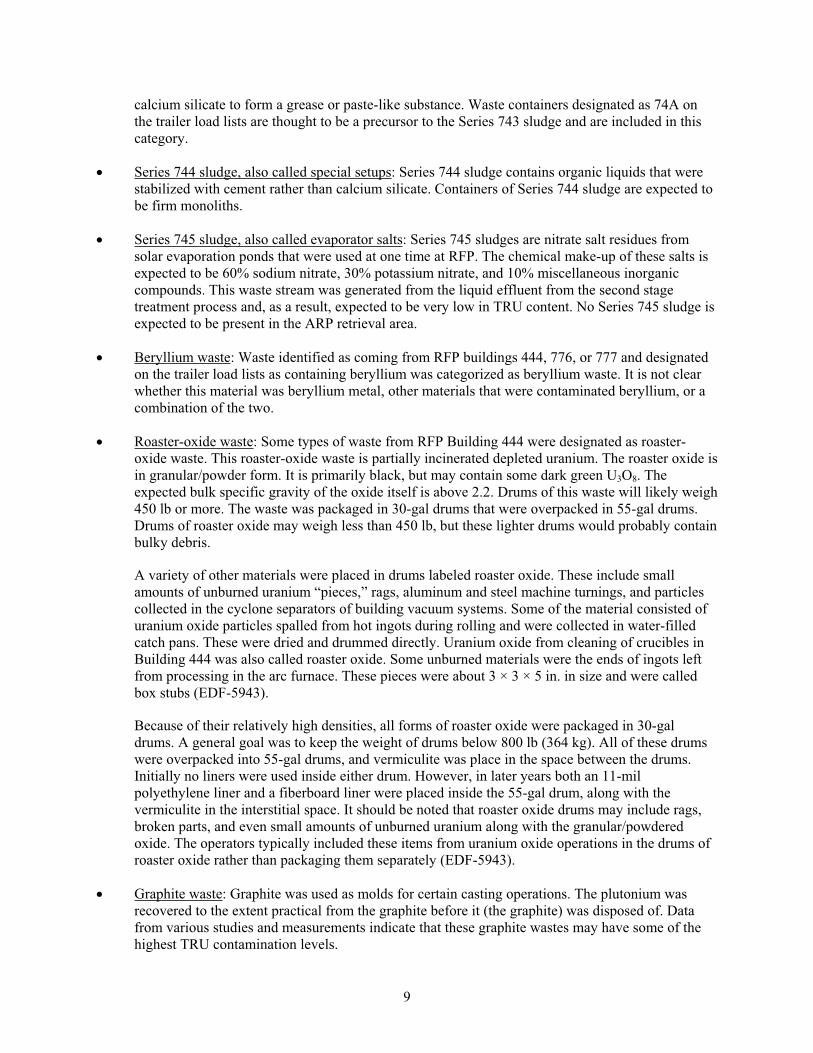
1.4.1 Description of Waste in the Pit
Pit 4 was open to receive waste from January 1963 through September 1967. Based on the disposal
practices at the time, containerized waste, primarily from RFP, was initially stacked in the pit. This
practice was later changed, and containers were dumped into the pits rather than stacked to reduce labor
costs and personnel radiation exposures. Based on retrieval information resulting from initial retrieval
activities, a portion of the waste in the west end of the original retrieval area is stacked. Inventory
information indicates that the waste in the remainder of the pit was most likely dumped rather than
stacked. Additional waste from INL Site waste generators and some waste from offsite generators also
were disposed of in the pit. The wastes identified by Acceptable Knowledge (AK) documentation
(EDF-4478) to be in the retrieval area include the following:
Series 741 sludge, also called first-stage sludge: Series 741 sludge was produced from aqueous
wastes from various plutonium recovery operations. The process produced a precipitate of hydrated
oxides of iron, magnesium, aluminum, and silicon that also carried some hydrate plutonium and
americium oxides. The precipitates were filtered to produce a sludge containing 50 to 70 wt%
water. The water was absorbed, to some extent, by the addition of Portland cement.
Series 742 sludge, also called second-stage sludge: Series 742 sludge was generated in a process
similar to the Series 741 sludge from various RFP aqueous streams that were lower in TRU content
than the streams generating the Series 741 sludge and generally contain lesser amounts of
plutonium or americium.
Series 743 sludge, also called organic setups: Series 743 sludge is very different from the
Series 741 and 742 types of sludge. Series 743 sludge is the result of stabilizing various organic
wastes (e.g., carbon tetrachloride, trichloroethylene, tetrachloroethylene, Texaco Regal Oil, and
other miscellaneous oils and degreasing agents). These types of liquid waste were mixed with
9
calcium silicate to form a grease or paste-like substance. Waste containers designated as 74A on
the trailer load lists are thought to be a precursor to the Series 743 sludge and are included in this
category.
Series 744 sludge, also called special setups: Series 744 sludge contains organic liquids that were
stabilized with cement rather than calcium silicate. Containers of Series 744 sludge are expected to
be firm monoliths.
Series 745 sludge, also called evaporator salts: Series 745 sludges are nitrate salt residues from
solar evaporation ponds that were used at one time at RFP. The chemical make-up of these salts is
expected to be 60% sodium nitrate, 30% potassium nitrate, and 10% miscellaneous inorganic
compounds. This waste stream was generated from the liquid effluent from the second stage
treatment process and, as a result, expected to be very low in TRU content. No Series 745 sludge is
expected to be present in the ARP retrieval area.
Beryllium waste: Waste identified as coming from RFP buildings 444, 776, or 777 and designated
on the trailer load lists as containing beryllium was categorized as beryllium waste. It is not clear
whether this material was beryllium metal, other materials that were contaminated beryllium, or a
combination of the two.
Roaster-oxide waste: Some types of waste from RFP Building 444 were designated as roaster-
oxide waste. This roaster-oxide waste is partially incinerated depleted uranium. The roaster oxide is
in granular/powder form. It is primarily black, but may contain some dark green U3O8. The
expected bulk specific gravity of the oxide itself is above 2.2. Drums of this waste will likely weigh
450 lb or more. The waste was packaged in 30-gal drums that were overpacked in 55-gal drums.
Drums of roaster oxide may weigh less than 450 lb, but these lighter drums would probably contain
bulky debris.
A variety of other materials were placed in drums labeled roaster oxide. These include small
amounts of unburned uranium “pieces,” rags, aluminum and steel machine turnings, and particles
collected in the cyclone separators of building vacuum systems. Some of the material consisted of
uranium oxide particles spalled from hot ingots during rolling and were collected in water-filled
catch pans. These were dried and drummed directly. Uranium oxide from cleaning of crucibles in
Building 444 was also called roaster oxide. Some unburned materials were the ends of ingots left
from processing in the arc furnace. These pieces were about 3 × 3 × 5 in. in size and were called
box stubs (EDF-5943).
Because of their relatively high densities, all forms of roaster oxide were packaged in 30-gal
drums. A general goal was to keep the weight of drums below 800 lb (364 kg). All of these drums
were overpacked into 55-gal drums, and vermiculite was place in the space between the drums.
Initially no liners were used inside either drum. However, in later years both an 11-mil
polyethylene liner and a fiberboard liner were placed inside the 55-gal drum, along with the
vermiculite in the interstitial space. It should be noted that roaster oxide drums may include rags,
broken parts, and even small amounts of unburned uranium along with the granular/powdered
oxide. The operators typically included these items from uranium oxide operations in the drums of
roaster oxide rather than packaging them separately (EDF-5943).
Graphite waste: Graphite was used as molds for certain casting operations. The plutonium was
recovered to the extent practical from the graphite before it (the graphite) was disposed of. Data
from various studies and measurements indicate that these graphite wastes may have some of the
highest TRU contamination levels.
10
Filters: This category is expected to contain the various high-efficiency particulate air filters. Other
types of process filters may also be included in the shipments designated as filters in WILD (Waste
Information and Location Database).
Line-generated waste: This category is expected to contain various waste materials removed from
the plutonium-processing gloveboxes including items such as glovebox gloves, combustible waste,
graphite, and filters.
Combustible debris: Waste comprising paper, plastic, wood, and other combustible materials was
designated as combustible debris.
Metal debris: Waste that was predominantly metallic (e.g., pipe, conduit, and empty drums) was
designated as metal debris.
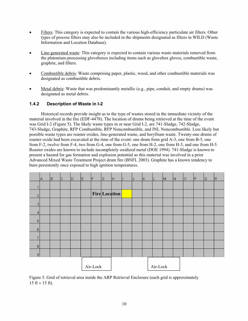
1.4.2 Description of Waste in I-2
Historical records provide insight as to the type of wastes stored in the immediate vicinity of the
material involved in the fire (EDF-4478). The location of drums being retrieved at the time of the event
was Grid I-2 (Figure 5). The likely waste types in or near Grid I-2, are 741-Sludge, 742-Sludge,
743-Sludge, Graphite, RFP Combustible, RFP Noncombustible, and INL Noncombustible. Less likely but
possible waste types are roaster oxides, line-generated waste, and beryllium waste. Twenty-one drums of
roaster oxide had been excavated at the time of the event: one drum from grid A-3, one from B-5, one
from F-2, twelve from F-4, two from G-4, one from G-5, one from H-2, one from H-3, and one from H-5.
Roaster oxides are known to include incompletely oxidized metal (DOE 1994). 741-Sludge is known to
present a hazard for gas formation and explosion potential as this material was involved in a prior
Advanced Mixed Waste Treatment Project drum fire (BNFL 2003). Graphite has a known tendency to
burn persistently once exposed to high ignition temperatures.
Figure 5. Grid of retrieval area inside the ARP Retrieval Enclosure (each grid is approximately
15 ft 15 ft).
Air-Lock Air-Lock
Fire Location
11
2. INVESTIGATION SCOPE, PURPOSE, AND METHODOLOGY
The independent team was chartered by the Vice President in charge of RWMC to determine the
cause of the drum fire/explosion, identify organizational and process weaknesses, analyze potential gaps
in hazards analysis, develop recommendations regarding the path forward to sampling and investigation
of the fire site, and recommend corrective actions based on our findings. The team included DOE,
CH2M-WG Idaho, LLC (CWI), and subcontracted personnel with a wide range of expertise.
Additionally, nationally recognized experts in several areas were used as advisors to the team.
Biographical information on the team is included in Appendix A. The Investigation began onsite
interviews on November 29, 2005, and concluded on February 23, 2006.
A detailed investigation plan is included as Appendix B. Standard event investigation processes
were used and included the following:
Gathering facts through interviews, document reviews, walk-downs of the work areas and detailed
investigation of the event scene.
Analyzing facts and identifying causes through approved analysis techniques by qualified cause
analysis personnel.
Development of recommended corrective actions.
This document provides the team’s analysis, conclusions and recommendations to the CWI Vice
President in charge of RWMC Operations.
12
3. DESCRIPTION OF EVENT
3.1 Operator Description of the Event
The following description of events is based on the information that was provided by the excavator
operator in written statements and interviews. Review of the video evidence of the event supports the
operator’s descriptions, although the actual fire and the trench internals are not visible in the video.
On November 21, 2005, the excavator operator retrieved, vented, and placed three drums from the
pit in a group on the surface level of the RE (referred to as the deck). He saw an additional group of three
drums and decided to retrieve these drums prior to assisting the telehandler operator with dirt moving
operations. The operator stated that he normally punctures the drums with the excavator “thumb” while he
is picking them up and lifts them directly up to the deck. The operator in this case decided to vent all three
drums and set them down in the trench prior to moving them to the deck. The operator retrieved and
vented one drum. The operator placed this drum in the bottom of the trench and it fell onto its side. The
operator retrieved and vented the second drum and set it next to the first. While the operator was in the
process of rotating the excavator to retrieve the third drum, he heard a loud noise and almost immediately
heard something hit the excavator cab window. When he looked, he saw a large ball of flame around the
second drum. The flames appeared to potentially also engulf the first drum. The excavator operator
initially attempted to use the dust suppression spray to extinguish the fire. The fire appeared to still be
growing. The operator started placing dirt over the fire. The dirt initially knocked down the fire. The fire
then began to extend up through the dirt. The operator keyed his microphone and reported the fire to his
supervisor and the camera operator. The operator placed additional dirt on the fire and used the dust
suppression spray until fire and smoke were no longer visible. The facility was placed in the warm
standby mode. Facility management was first informed by operator of the loud bang and material hitting
the cab of the excavator at the critique. Facility management then determined that an explosion may have
occurred and the appropriate reporting occurred.
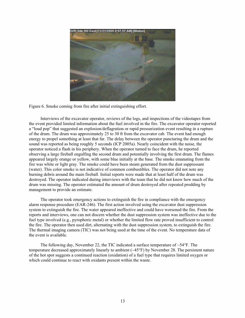
3.2 Additional Information from the Evidence Available
Based on review of the video evidence of the event, the team determined that it occurred at
approximately 09:56 on November 21, 2005, while the camera operator had moved the camera to look at
other operations in the ARP enclosure. There is a period of approximately 20 seconds where the
excavator is not in view. When the camera is initially positioned to see the excavator again, there is no
visual evidence (such as a plume or overhead material movement) that any event had occurred. After the
fire is reported, the camera operator zoomed in on the excavation and white smoke was visible (Figure 6).
The excavator operator and the telehandler operator were the only personnel in RE when the event
occurred. A number of personnel were in the airlocks attached to the RE. With the exception of the
excavator operator, no one interviewed heard or saw anything when the event occurred.
13
Figure 6. Smoke coming from fire after initial extinguishing effort.
Interviews of the excavator operator, reviews of the logs, and inspections of the videotapes from
the event provided limited information about the fuel involved in the fire. The excavator operator reported
a “loud pop” that suggested an explosion/deflagration or rapid pressurization event resulting in a rupture
of the drum. The drum was approximately 25 to 30 ft from the excavator cab. The event had enough
energy to propel something at least that far. The delay between the operator puncturing the drum and the
sound was reported as being roughly 5 seconds (ICP 2005a). Nearly coincident with the noise, the
operator noticed a flash in his periphery. When the operator turned to face the drum, he reported
observing a large fireball engulfing the second drum and potentially involving the first drum. The flames
appeared largely orange or yellow, with some blue initially at the base. The smoke emanating from the
fire was white or light gray. The smoke could have been steam generated from the dust suppressant
(water). This color smoke is not indicative of common combustibles. The operator did not note any
burning debris around the main fireball. Initial reports were made that at least half of the drum was
destroyed. The operator indicated during interviews with the team that he did not know how much of the
drum was missing. The operator estimated the amount of drum destroyed after repeated prodding by
management to provide an estimate.
The operator took emergency actions to extinguish the fire in compliance with the emergency
alarm response procedure (EAR-246). The first action involved using the excavator dust suppression
system to extinguish the fire. The water appeared ineffective and could have worsened the fire. From the
reports and interviews, one can not discern whether the dust suppression system was ineffective due to the
fuel type involved (e.g., pyrophoric metal) or whether the limited flow rate proved insufficient to control
the fire. The operator then used dirt, alternating with the dust suppression system, to extinguish the fire.
The thermal imaging camera (TIC) was not being used at the time of the event. No temperature data of
the event is available.
The following day, November 22, the TIC indicated a surface temperature of ~54°F. The
temperature decreased approximately linearly to ambient (~45°F) by November 28. The persistent nature
of the hot spot suggests a continued reaction (oxidation) of a fuel type that requires limited oxygen or
which could continue to react with oxidants present within the waste.
14
4. SCENE INVESTIGATION
The Project developed a recovery plan to obtain the necessary samples to make a positive
identification of the fuel source/material of concern. An evaluation of safety significance was written and
presented to DOE for approval to ensure a safety basis existed for the sample activities. The sampling
activity was conducted in a two phased approach.
4.1 Phase 1 Initial Sampling
The initial sampling operation was planned to include excavation until the drum that was the source
of the event was located, placing a portion of the soil/material around the drum top in a tray for sampling
and then covering the drum with soil. Additionally, soil from the pile of dirt used to extinguish the fire
was placed in a tray and sampled to provide a baseline for comparison. The sampling process was
performed in the DPS. If the samples proved conclusive, no further sampling would be performed. This
evolution was performed on January 26, 2006. The operator who was in the excavator when the event
occurred was the excavator operator for this sampling operation.
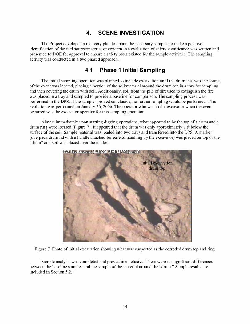
Almost immediately upon starting digging operations, what appeared to be the top of a drum and a
drum ring were located (Figure 7). It appeared that the drum was only approximately 1 ft below the
surface of the soil. Sample material was loaded into two trays and transferred into the DPS. A marker
(overpack drum lid with a handle attached for ease of handling by the excavator) was placed on top of the
“drum” and soil was placed over the marker.
Figure 7. Photo of initial excavation showing what was suspected as the corroded drum top and ring.
Sample analysis was completed and proved inconclusive. There were no significant differences
between the baseline samples and the sample of the material around the “drum.” Sample results are
included in Section 5.2.
Initial excavation
drum top
15
4.2 Phase 2 Sampling of Drum Contents
Based on inconclusive results, a second sampling evolution was planned that involved opening and
sampling the actual contents of the drum that was the source of this event. The plan included excavation
and inspection of the drum, opening and sampling the drum contents, and location and inspection of the
other drum that had been placed in the area prior to the event. On February 14, 2006, the second phase of
sampling was conducted.
After location and removal of the marker, the operator began digging in front of the ‘drum’
location to expose the body of the drum. After digging down several feet, the drum ring slid down and the
dirt pile collapsed. Apparently, the drum ring and other debris in the area had formed what looked like a
drum top through the camera.
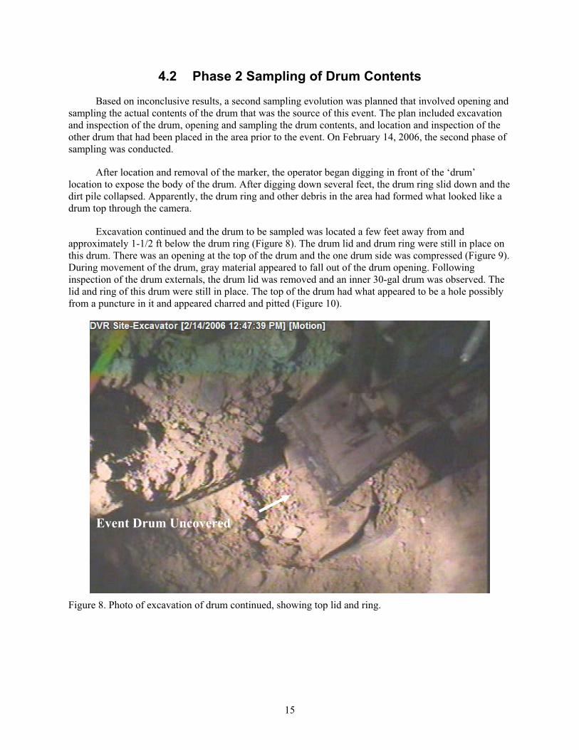
Excavation continued and the drum to be sampled was located a few feet away from and
approximately 1-1/2 ft below the drum ring (Figure 8). The drum lid and drum ring were still in place on
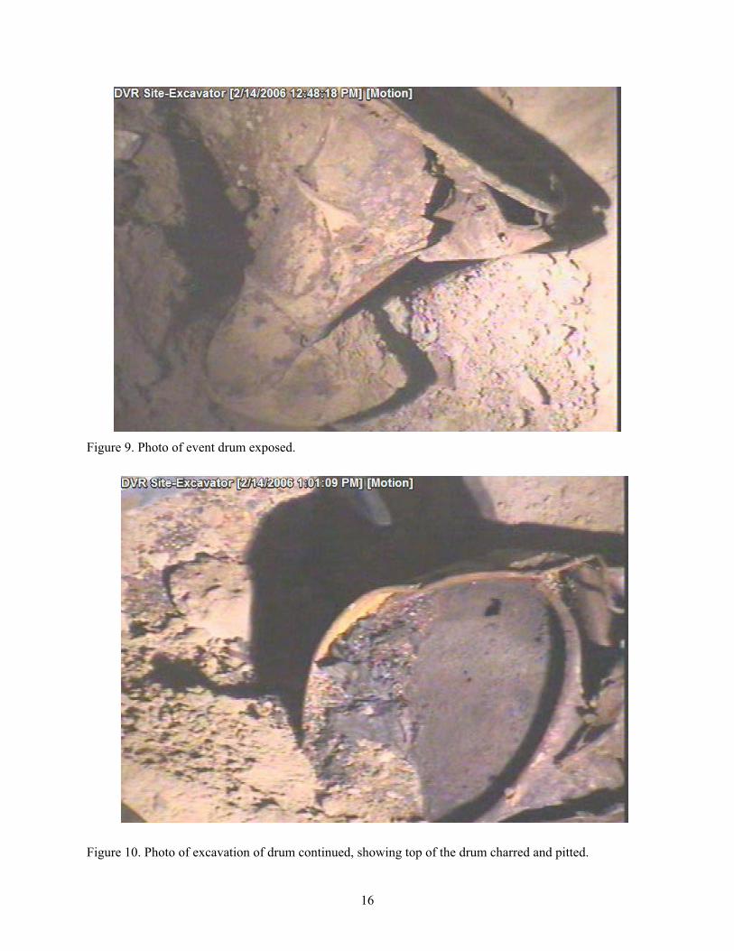
this drum. There was an opening at the top of the drum and the one drum side was compressed (Figure 9).
During movement of the drum, gray material appeared to fall out of the drum opening. Following
inspection of the drum externals, the drum lid was removed and an inner 30-gal drum was observed. The
lid and ring of this drum were still in place. The top of the drum had what appeared to be a hole possibly
from a puncture in it and appeared charred and pitted (Figure 10).
Figure 8. Photo of excavation of drum continued, showing top lid and ring.
Event Drum Uncovered
16
Figure 9. Photo of event drum exposed.
Figure 10. Photo of excavation of drum continued, showing top of the drum charred and pitted.
17
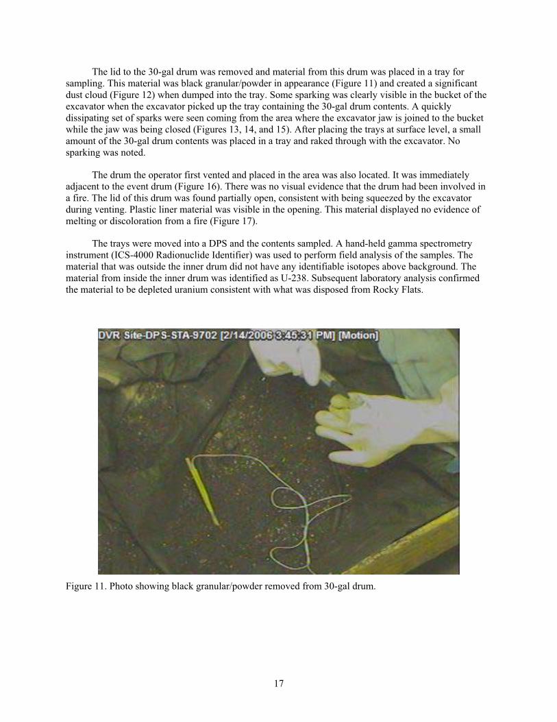
The lid to the 30-gal drum was removed and material from this drum was placed in a tray for
sampling. This material was black granular/powder in appearance (Figure 11) and created a significant
dust cloud (Figure 12) when dumped into the tray. Some sparking was clearly visible in the bucket of the
excavator when the excavator picked up the tray containing the 30-gal drum contents. A quickly
dissipating set of sparks were seen coming from the area where the excavator jaw is joined to the bucket
while the jaw was being closed (Figures 13, 14, and 15). After placing the trays at surface level, a small
amount of the 30-gal drum contents was placed in a tray and raked through with the excavator. No
sparking was noted.
The drum the operator first vented and placed in the area was also located. It was immediately
adjacent to the event drum (Figure 16). There was no visual evidence that the drum had been involved in
a fire. The lid of this drum was found partially open, consistent with being squeezed by the excavator
during venting. Plastic liner material was visible in the opening. This material displayed no evidence of
melting or discoloration from a fire (Figure 17).
The trays were moved into a DPS and the contents sampled. A hand-held gamma spectrometry
instrument (ICS-4000 Radionuclide Identifier) was used to perform field analysis of the samples. The
material that was outside the inner drum did not have any identifiable isotopes above background. The
material from inside the inner drum was identified as U-238. Subsequent laboratory analysis confirmed
the material to be depleted uranium consistent with what was disposed from Rocky Flats.
Figure 11. Photo showing black granular/powder removed from 30-gal drum.
18
Figure 12. Photo showing dumping of black granules into tray, causing dust cloud.
Figure 13. Photo showing sparks at jaw to bucket joint.
19
Figure 14. Photo showing sparks on both sides of the excavator bucket.
Figure 15. Photo showing sparks dissipating.
20
Figure 16. Photo showing drum next to event drum.
Figure 17. Photo showing drum next to event drum with no indication of fire.
21
5. DETERMINATION OF THE CAUSE OF THE FIRE
5.1 Sampling Logic
To facilitate identification of the fuel (or waste type) involved, the investigation team
recommended the following analyses:
Gamma spectroscopy of the retrieved solid and drum contents. Gamma measurements will indicate
the relative uranium content and isotopic distribution of the waste. Comparison of this data versus
historical knowledge (Haar 2005) for the waste types will help discern the fuel involved.
Elemental (Metals) Analysis. Digestion and elemental analysis will identify the primary metals
included in the waste. Personnel will look for elevated concentration of uranium, zirconium,
cadmium, beryllium, and other potentially pyrophoric metals that may have contributed to the
event. The analysis will also indicate if mercury metal is present in elevated quantities.
Volatile Organics Analysis (VOA). The visual evidence from the videotape of the fire suggests
unlikely involvement of substantial amounts of common combustibles or liquid solvents. However,
VOA will provide more definitive evidence. VOA may also indicate if any organo-mercury
compounds are present that may be shock-sensitive or potentially explosive.
Anion Analysis. Some of the line-generated wastes or other materials from Rocky Flats may
include melted salts from pyrochemical operations. Analysis of the anions in the collected soil –
and comparison with similar measurements on a control sample of soil from the area – might
exclude this waste type from consideration.
X-Ray Diffraction (XRD). XRD analysis the samples will provide molecular identification of the
material involved. Determination of the degree of oxidation for any uranium present will provide
insight as to whether incompletely oxidized roaster oxides were involved in the fire. If present in
sufficient mass, this analysis will also determine the presence on nitrate salts and inorganic
oxidants.
Total Inorganic Carbon/Total Organic Carbon (TIC/TOC). This analysis will determine the amount
of carbon present including insight as to the amount of graphite.
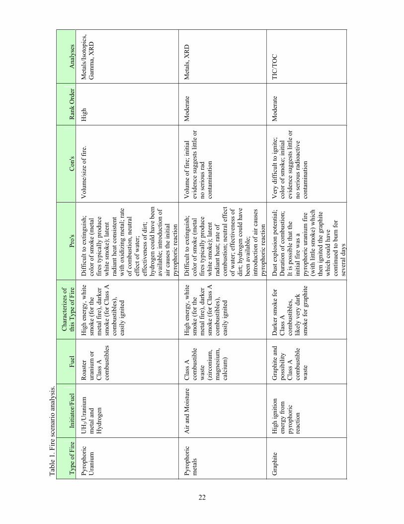
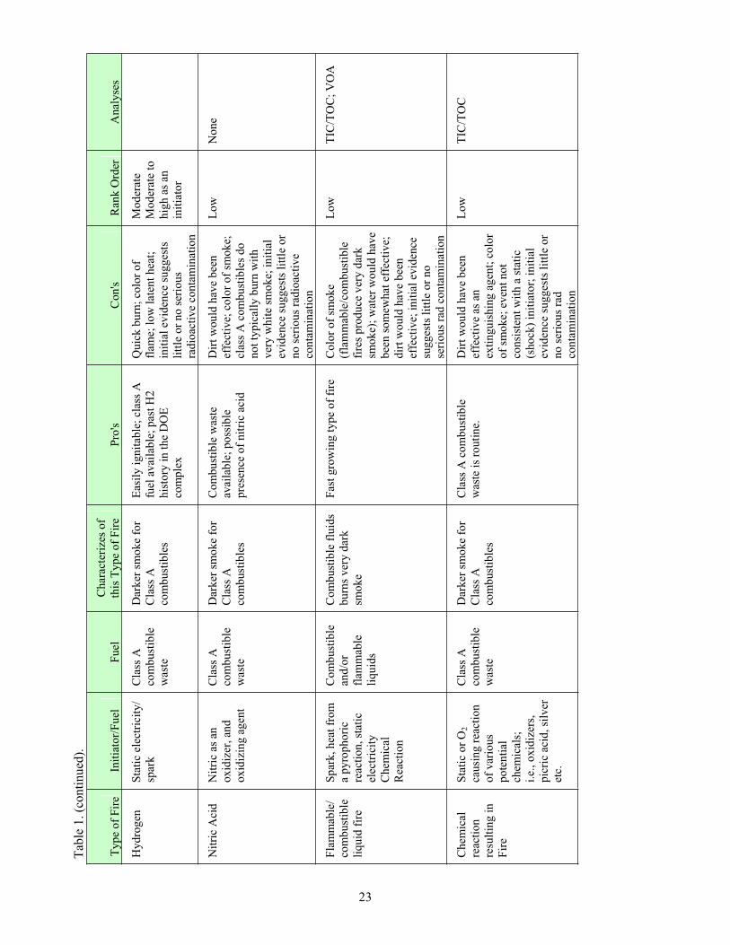
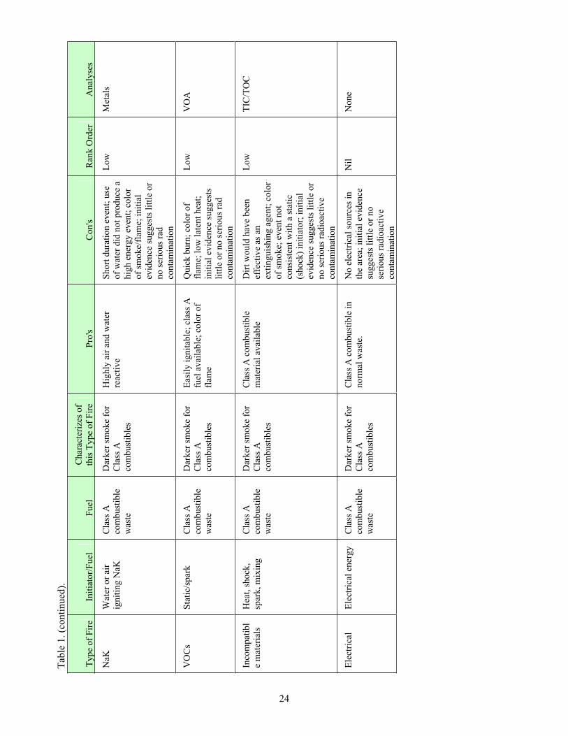
5.1.1 Potential Scenario Analysis
Table 1 lists potential fuel types and initiators. The table includes common characteristics of the
fires for the various fuels and a ranking by the investigation team of the likelihood that the incident
involved the given fuel (or waste) type. The investigation team reviewed a number of references
regarding fire characteristics in development of the table (DOE 1994; Zerwekh 1979; Molecke, 1979).
Given the description of the event and the potential involvement of multiple waste drums in the event, the
potential existed that the initiating event and the persistent fire could involve two distinct waste types.
22
Tab
le 1
. F
ire
scen
ario
an
aly
sis.
Ty
pe
of
Fir
e In
itia
tor/
Fuel
F
uel
Char
acte
rize
s of
this
Type
of
Fir
e P
ro's
C
on
's
Ran
k O
rder
A
nal
yse
s
Pyro
phori
c
Ura
niu
m
UH
3/U
ran
ium
met
al a
nd
Hyd
rog
en
Roas
ter
ura
niu
m o
r
Cla
ss A
com
bu
stib
les
Hig
h e
ner
gy
, w
hit
e
smo
ke
(fo
r th
e
met
al f
ire)
, dar
ker
smoke
(for
Cla
ss A
com
bust
ible
s),
easi
ly i
gnit
ed
Dif
ficu
lt t
o e
xti
ngu
ish
;
colo
r o
f sm
ok
e (m
etal
fire
s ty
pic
ally
pro
du
ce
whit
e sm
oke)
; la
tent
radia
nt
hea
t co
nsi
sten
t
wit
h o
xid
izin
g m
etal
; ra
te
of
com
bu
stio
n, n
eutr
al
effe
ct o
f w
ater
;
effe
ctiv
enes
s of
dir
t;
hydro
gen
co
uld
hav
e b
een
avai
lable
; in
troduct
ion o
f
air
cause
s th
e in
itia
l
py
rop
ho
ric
reac
tio
n
Vo
lum
e/si
ze o
f fi
re.
H
igh
M
etal
s/Is
oto
pic
s,
Gam
ma,
XR
D
Pyro
phori
c
met
als
Air
and
Mo
istu
re
Cla
ss A
com
bu
stib
le
was
te
(zir
con
ium
,
mag
nes
ium
,
calc
ium
)
Hig
h e
ner
gy
, w
hit
e
smo
ke
(fo
r th
e
met
al f
ire)
, dar
ker
smoke
(for
Cla
ss A
com
bust
ible
s),
easi
ly i
gnit
ed
Dif
ficu
lt t
o e
xti
ngu
ish
;
colo
r o
f sm
ok
e (m
etal
fire
s ty
pic
ally
pro
du
ce
whit
e sm
oke)
; la
tent
radia
nt
hea
t; r
ate
of
com
bu
stio
n;
neu
tral
eff
ect
of
wat
er;
effe
ctiv
enes
s o
f
dir
t; h
yd
rog
en c
ou
ld h
ave
bee
n a
vai
lable
;
intr
oduct
ion o
f ai
r ca
use
s
py
rop
ho
ric
reac
tio
n
Vo
lum
e o
f fi
re;
init
ial
evid
ence
sugges
ts l
ittl
e or
no
ser
iou
s ra
d
conta
min
atio
n
Mo
der
ate
Met
als,
XR
D
Gra
phit
e H
igh i
gnit
ion
ener
gy f
rom
pyro
pho
ric
reac
tio
n
Gra
phit
e an
d
po
ssib
ilit
y
Cla
ss A
com
bu
stib
le
was
te
Dar
ker
sm
ok
e fo
r
Cla
ss A
com
bu
stib
les,
likel
y v
ery d
ark
smo
ke
for
gra
ph
ite
Dust
explo
sion p
ote
nti
al;
Dura
tion
of
com
bu
stio
n;
It i
s poss
ible
that
the
init
ial
fire
was
a
py
rop
ho
ric
ura
niu
m f
ire
(wit
h l
ittl
e sm
oke)
whic
h
then
ignit
ed t
he
gra
phit
e
wh
ich
co
uld
hav
e
con
tinu
ed t
o b
urn
for
sever
al d
ays
Ver
y d
iffi
cult
to i
gnit
e;
colo
r of
smoke;
init
ial
evid
ence
sugges
ts l
ittl
e or
no
ser
iou
s ra
dio
acti
ve
conta
min
atio
n
Moder
ate
TIC
/TO
C
Tab
le 1
. (c
on
tin
ued
).
23
Ty
pe
of
Fir
e In
itia
tor/
Fuel
F
uel
Char
acte
rize
s of
this
Type
of
Fir
e P
ro's
C
on
's
Ran
k O
rder
A
nal
yse
s
Hydro
gen
S
tati
c el
ectr
icit
y/
spar
k
Cla
ss A
com
bu
stib
le
was
te
Dar
ker
sm
ok
e fo
r
Cla
ss A
com
bu
stib
les
Eas
ily i
gnit
able
; cl
ass
A
fuel
av
aila
ble
; pas
t H
2
his
tory
in
th
e D
OE
com
ple
x
Quic
k b
urn
; co
lor
of
flam
e; l
ow
lat
ent
hea
t;
init
ial
evid
ence
sugges
ts
litt
le o
r no s
erio
us
rad
ioac
tiv
e co
nta
min
atio
n
Mo
der
ate
Mo
der
ate
to
hig
h a
s an
init
iato
r
Nit
ric
Aci
d
Nit
ric
as a
n
ox
idiz
er, an
d
oxid
izin
g a
gen
t
Cla
ss A
com
bu
stib
le
was
te
Dar
ker
sm
ok
e fo
r
Cla
ss A
com
bu
stib
les
Com
bust
ible
was
te
avai
lable
; poss
ible
pre
sence
of
nit
ric
acid
Dir
t w
ou
ld h
ave
bee
n
effe
ctiv
e; c
olo
r of
smoke;
clas
s A
com
bust
ible
s do
not
typic
ally
burn
wit
h
ver
y w
hit
e sm
ok
e; i
nit
ial
evid
ence
sugges
ts l
ittl
e or
no
ser
iou
s ra
dio
acti
ve
conta
min
atio
n
Lo
w
No
ne
Fla
mm
able
/
com
bu
stib
le
liq
uid
fir
e
Sp
ark, h
eat
from
a p
yro
ph
ori
c
reac
tion,
stat
ic
elec
tric
ity
Chem
ical
Rea
ctio
n
Co
mb
ust
ible
and
/or
flam
mab
le
liq
uid
s
Co
mb
ust
ible
flu
ids
bu
rns
ver
y d
ark
smo
ke
Fas
t gro
win
g t
ype
of
fire
C
olo
r of
smoke
(fla
mm
able
/com
bust
ible
fire
s p
rod
uce
ver
y d
ark
smo
ke)
; w
ater
wo
uld
hav
e
bee
n s
om
ewh
at e
ffec
tiv
e;
dir
t w
ou
ld h
ave
bee
n
effe
ctiv
e; i
nit
ial
evid
ence
sugges
ts l
ittl
e or
no
seri
ous
rad c
onta
min
atio
n
Low
T
IC/T
OC
; V
OA
Chem
ical
reac
tion
resu
ltin
g i
n
Fir
e
Sta
tic
or
O2
causi
ng r
eact
ion
of
var
iou
s
po
ten
tial
chem
ical
s;
i.e.
, o
xid
izer
s,
pic
ric
acid
, si
lver
etc.
Cla
ss A
com
bu
stib
le
was
te
Dar
ker
sm
ok
e fo
r
Cla
ss A
com
bu
stib
les
Cla
ss A
com
bust
ible
was
te i
s ro
uti
ne.
Dir
t w
ou
ld h
ave
bee
n
effe
ctiv
e as
an
exti
ngu
ish
ing
ag
ent;
co
lor
of
smo
ke;
ev
ent
no
t
consi
sten
t w
ith a
sta
tic
(sho
ck)
init
iato
r; i
nit
ial
evid
ence
sugges
ts l
ittl
e or
no
ser
iou
s ra
d
conta
min
atio
n
Low
T
IC/T
OC
Tab
le 1
. (c
on
tin
ued
).
24
Ty
pe
of
Fir
e In
itia
tor/
Fuel
F
uel
Char
acte
rize
s of
this
Type
of
Fir
e P
ro's
C
on
's
Ran
k O
rder
A
nal
yse
s
NaK
W
ater
or
air
ignit
ing N
aK
Cla
ss A
com
bu
stib
le
was
te
Dar
ker
sm
ok
e fo
r
Cla
ss A
com
bu
stib
les
Hig
hly
air
an
d w
ater
reac
tive
Short
dura
tion e
ven
t; u
se
of
wat
er d
id n
ot
pro
du
ce a
hig
h e
ner
gy e
ven
t; c
olo
r
of
smoke/
flam
e; i
nit
ial
evid
ence
sugges
ts l
ittl
e or
no
ser
iou
s ra
d
conta
min
atio
n
Low
M
etal
s
VO
Cs
Sta
tic/
spar
k
Cla
ss A
com
bu
stib
le
was
te
Dar
ker
sm
ok
e fo
r
Cla
ss A
com
bu
stib
les
Eas
ily i
gnit
able
; cl
ass
A
fuel
av
aila
ble
; co
lor
of
flam
e
Quic
k b
urn
; co
lor
of
flam
e; l
ow
lat
ent
hea
t;
init
ial
evid
ence
sugges
ts
litt
le o
r no s
erio
us
rad
conta
min
atio
n
Lo
w
VO
A
Inco
mp
atib
l
e m
ater
ials
Hea
t, s
ho
ck,
spar
k, m
ixin
g
Cla
ss A
com
bu
stib
le
was
te
Dar
ker
sm
ok
e fo
r
Cla
ss A
com
bu
stib
les
Cla
ss A
com
bust
ible
mat
eria
l av
aila
ble
Dir
t w
ou
ld h
ave
bee
n
effe
ctiv
e as
an
exti
ngu
ish
ing
ag
ent;
co
lor
of
smo
ke;
ev
ent
no
t
consi
sten
t w
ith a
sta
tic
(sho
ck)
init
iato
r; i
nit
ial
evid
ence
sugges
ts l
ittl
e or
no
ser
iou
s ra
dio
acti
ve
conta
min
atio
n
Low
T
IC/T
OC
Ele
ctri
cal
Ele
ctri
cal
ener
gy
Cla
ss A
com
bu
stib
le
was
te
Dar
ker
sm
ok
e fo
r
Cla
ss A
com
bu
stib
les
Cla
ss A
com
bust
ible
in
no
rmal
was
te.
No e
lect
rica
l so
urc
es i
n
the
area
; in
itia
l ev
iden
ce
sugges
ts l
ittl
e or
no
seri
ou
s ra
dio
acti
ve
conta
min
atio
n
Nil
N
one
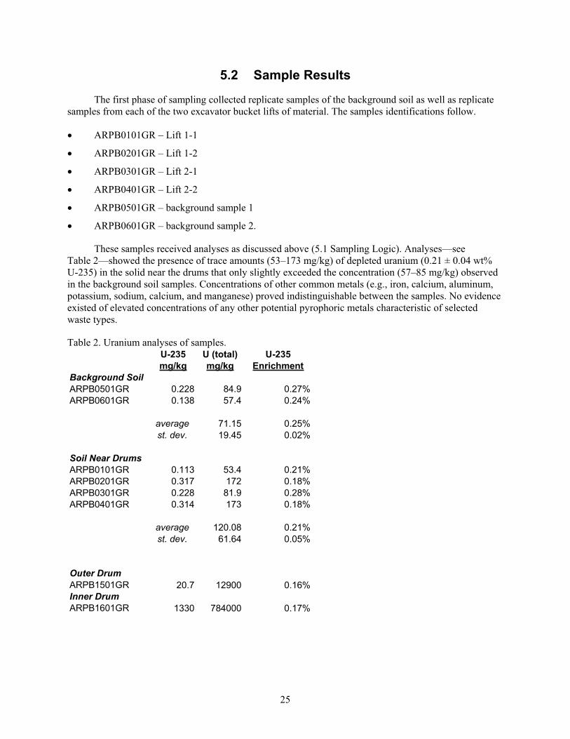
25
5.2 Sample Results
The first phase of sampling collected replicate samples of the background soil as well as replicate
samples from each of the two excavator bucket lifts of material. The samples identifications follow.
ARPB0101GR – Lift 1-1
ARPB0201GR – Lift 1-2
ARPB0301GR – Lift 2-1
ARPB0401GR – Lift 2-2
ARPB0501GR – background sample 1
ARPB0601GR – background sample 2.
These samples received analyses as discussed above (5.1 Sampling Logic). Analyses—see
Table 2—showed the presence of trace amounts (53–173 mg/kg) of depleted uranium (0.21 ± 0.04 wt%
U-235) in the solid near the drums that only slightly exceeded the concentration (57–85 mg/kg) observed
in the background soil samples. Concentrations of other common metals (e.g., iron, calcium, aluminum,
potassium, sodium, calcium, and manganese) proved indistinguishable between the samples. No evidence
existed of elevated concentrations of any other potential pyrophoric metals characteristic of selected
waste types.
Table 2. Uranium analyses of samples. U-235 U (total) U-235
mg/kg mg/kg Enrichment
Background SoilARPB0501GR 0.228 84.9 0.27%
ARPB0601GR 0.138 57.4 0.24%
average 71.15 0.25%
st. dev. 19.45 0.02%
Soil Near DrumsARPB0101GR 0.113 53.4 0.21%
ARPB0201GR 0.317 172 0.18%
ARPB0301GR 0.228 81.9 0.28%
ARPB0401GR 0.314 173 0.18%
average 120.08 0.21%
st. dev. 61.64 0.05%
Outer Drum ARPB1501GR 20.7 12900 0.16%
Inner Drum ARPB1601GR 1330 784000 0.17%
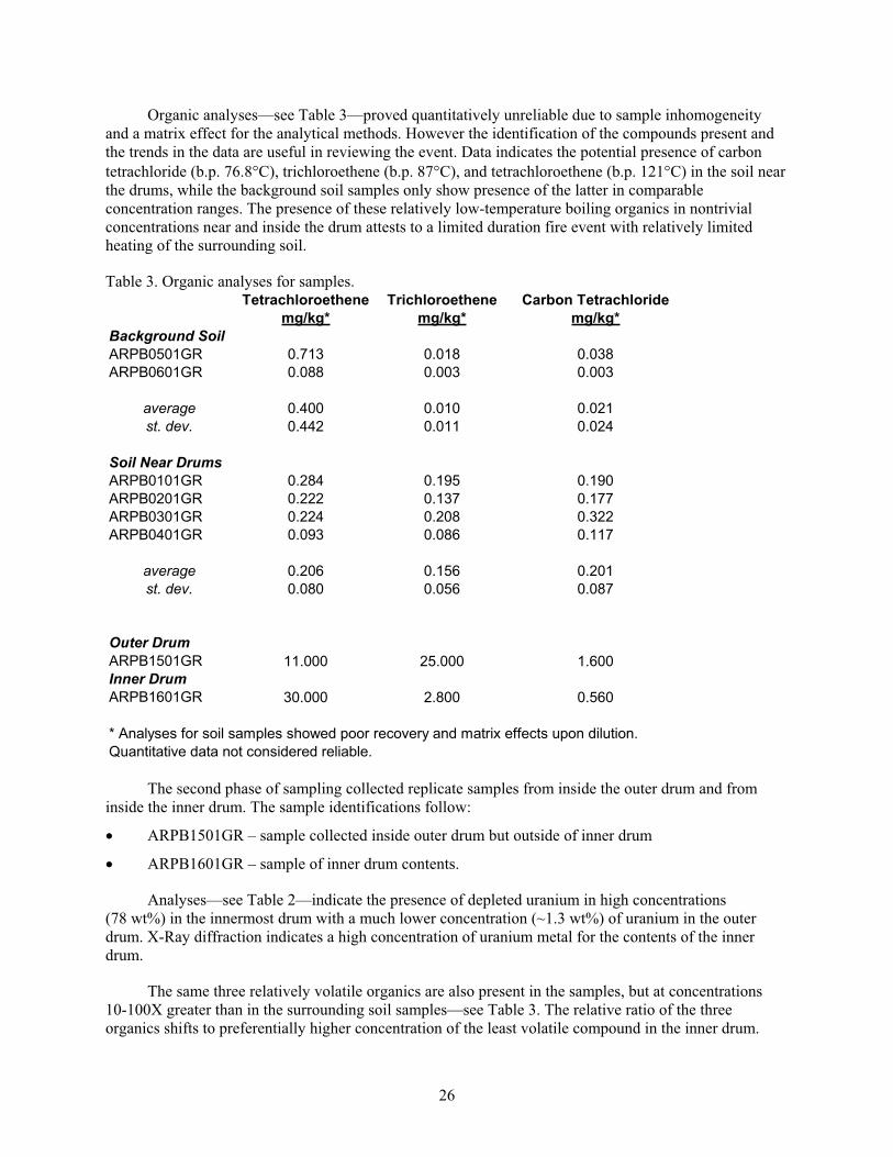
26
Organic analyses—see Table 3—proved quantitatively unreliable due to sample inhomogeneity
and a matrix effect for the analytical methods. However the identification of the compounds present and
the trends in the data are useful in reviewing the event. Data indicates the potential presence of carbon
tetrachloride (b.p. 76.8 C), trichloroethene (b.p. 87 C), and tetrachloroethene (b.p. 121 C) in the soil near
the drums, while the background soil samples only show presence of the latter in comparable
concentration ranges. The presence of these relatively low-temperature boiling organics in nontrivial
concentrations near and inside the drum attests to a limited duration fire event with relatively limited
heating of the surrounding soil.
Table 3. Organic analyses for samples. Tetrachloroethene Trichloroethene Carbon Tetrachloride
mg/kg* mg/kg* mg/kg*
Background SoilARPB0501GR 0.713 0.018 0.038
ARPB0601GR 0.088 0.003 0.003
average 0.400 0.010 0.021
st. dev. 0.442 0.011 0.024
Soil Near DrumsARPB0101GR 0.284 0.195 0.190
ARPB0201GR 0.222 0.137 0.177
ARPB0301GR 0.224 0.208 0.322
ARPB0401GR 0.093 0.086 0.117
average 0.206 0.156 0.201
st. dev. 0.080 0.056 0.087
Outer Drum ARPB1501GR 11.000 25.000 1.600
Inner Drum ARPB1601GR 30.000 2.800 0.560
* Analyses for soil samples showed poor recovery and matrix effects upon dilution.
Quantitative data not considered reliable.
The second phase of sampling collected replicate samples from inside the outer drum and from
inside the inner drum. The sample identifications follow:
ARPB1501GR – sample collected inside outer drum but outside of inner drum
ARPB1601GR – sample of inner drum contents.
Analyses—see Table 2—indicate the presence of depleted uranium in high concentrations
(78 wt%) in the innermost drum with a much lower concentration (~1.3 wt%) of uranium in the outer
drum. X-Ray diffraction indicates a high concentration of uranium metal for the contents of the inner
drum.
The same three relatively volatile organics are also present in the samples, but at concentrations
10-100X greater than in the surrounding soil samples—see Table 3. The relative ratio of the three
organics shifts to preferentially higher concentration of the least volatile compound in the inner drum.
27
This trend might suggest that the fire either vaporized or burned more of the volatile organics inside the
inner drum than occurred for the outer drum or the surrounding soil. Such a trend is consistent with the
highest temperature spot being within the innermost drum and hence that the fire started within that drum.
5.3 Depleted Uranium Oxidation Process and Fire History
The roaster oxide produced at the Rocky Flats Plant came from the process used for stabilizing
uranium metal machine turnings by oxidation. Uranium oxidizes (burns) at a very slow rate. The Rocky
Flats Plant process did not allow sufficient roasting time or provide adequate size reduction to fully
oxidize all material types. This resulted in a partially-oxidized mixture of uranium oxide, finely divided
metal and uranium sub-oxide. This mixture of uranium known as “roaster oxide” was sealed in 30-gal
drums and then placed in larger 55-gal drums for shipment to the INL Site.
Uranium metal burns at a very slow rate. Oxide formed on the surface of the burning metal inhibits
the burning process by restricting access to oxygen. The oxide formed by the burning metal is about one
third the density of the metal. The oxidation process takes place on the surface as well as along the grain
boundaries of the metal. This causes metal flakes to form. If the material is sealed in a drum before it
completely oxidizes, the metal flakes resulting from continued oxidation are very reactive (pyrophoric)
and will ignite when exposed to air. This behavior also occurs for other metals such as thorium,
plutonium and zirconium.
Burning uranium does not produce a flame. The flames produced when roaster oxide burns come
from the hydrogen produced by decomposition of uranium hydride. Uranium hydride forms by the
reaction of water or plastics with uranium metal. Buried uranium metal will react, or corrode, with the
water vapor to form hydride on the surface. Such corrosion likely occurred during the storage of the
buried drum within the oxygen-deficient atmosphere, and the availability of moisture increased the
amount of hydride formed. The operations of November 21 likely disrupted the fine hydride powder and
allowed air to ignite the compound. The presence of uranium metal and hydride allowed for a persistent
fire. The heat decomposes the uranium hydride, resulting in a flame. Some uranium machine turnings
were stored under oil, which was not always destroyed by the roasting process. The carbon and hydrogen
for such residues also contribute to the propagation of a flame.
In 1970, a barrel of roaster oxide received at the RWMC was found to be burning. It was buried
without opening the barrels or determining the cause of the fire. Experience at uranium processing centers
such as the Fernald, Hanford, and Y-12 Facilities with uranium fires were documented in the 1950s (UNC
Nuclear Industries 1954). Thorium equivalent of roaster oxide produced barrel fires at Fernald when the
barrels were punctured and air was introduced. Fires with metal turnings were so numerous that most sites
did not keep count of the incidents. The standard way of dealing with uranium metal turnings was to store
them under water. It was only when shipment to another site was required that the turnings were partially
oxidized as a “roaster.”
Fires should be anticipated and planned for during excavation of barrels of roaster oxide. With
adequate separation from other combustible materials, drums could be safely vented and opened. The best
method of handling a fire, from an oxidation and further handling of material standpoint, would be to
isolate the material from other combustible and drums, and allow controlled amounts of the drum contents
to burn. The amount of hydride present is anticipated to be limited such that the flames should not last
more than a few minutes. The burning oxide and metal fines could continue to burn for several hours to
several days. Once this burning process is completed, the material could be tested to ensure it is fully
oxidized prior to further handling (sampling/packing) for disposal. This course of action would require
rigorous review for potential additional hazards caused by the fumes and would require consultation with
applicable regulators.
28
5.4 Likely Fire Initiation Scenario
Based on the evidence available the following is the most likely scenario: During the process of
venting the drum, the inner drum was also punctured. Oxygen introduction into the inner drum caused a
rapid oxidation reaction that included the release of hydrogen from uranium hydride and resulted in a fire.
It is likely that hydrogen and volatile organic compounds contributed fuel to the fire. The fire rapidly
expelled the majority of the material in the area above the inner drum and some of this material hit the
excavator cab. It is likely that the visible flames were created from several openings around the top of the
drum. Following extinguishment of the initial fire, the uranium continued to burn under the soil. The
adjacent drum was not involved as source of fuel for the fire. There is no physical evidence that an
explosion occurred. Neither drum shows deformations (i.e., outward bulging areas) consistent with those
expected from an explosion.
5.5 Cause
The fire resulted from oxygen (i.e., air) intrusion and contact with disrupted pyrophoric material
(i.e., incompletely roasted depleted uranium) during excavation and venting of the drum. It is likely that
this fire would have occurred when the inner drum was vented either during the excavation process or
during the subsequent sampling campaign being planned for roaster oxide drums.
Based on the type of waste being excavated, how the waste was originally placed in the pit, and the
condition of the waste, the team did not find fault with the excavation method selected by the project.
Additionally, even if all the recommendations of this report are fully and effectively implemented, a
similar event is likely to occur. See Figure 18 (events and conditions summary diagram) and Table 4
(barrier analysis chart).
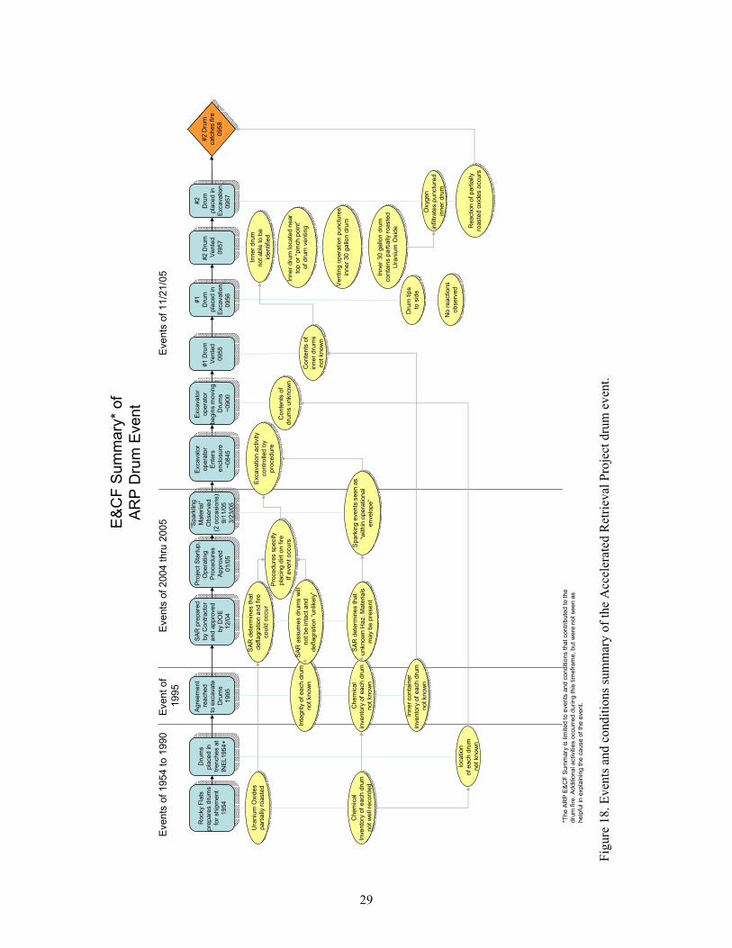
29
E&
CF
Sum
mary
* of
AR
P D
rum
Event
#2
Dru
m
catc
hes f
ire
09
58
#2 D
rum
catc
hes fir
e
095
8
Exca
va
tor
ope
rato
r
be
gin
s m
ovin
g
Dru
ms
~0
900
Exca
va
tor
ope
rato
r
be
gin
s m
ovin
g
Dru
ms
~09
00
Oxyg
en
infiltra
tes p
un
ctu
red
inne
r dru
m
Oxyg
en
infiltra
tes p
unctu
red
inne
r dru
m
Co
nte
nts
of
inn
er
dru
ms
no
t kno
wn
Co
nte
nts
of
inn
er
dru
ms
no
t kno
wn
Co
nte
nts
of
dru
ms u
nkn
ow
n
Co
nte
nts
of
dru
ms u
nkn
ow
n
#1
Dru
m
Ve
nte
d
095
5
#1
Dru
m
Ve
nte
d
09
55
#1
Dru
m
pla
ce
d in
Excava
tio
n
09
56
#1
Dru
m
pla
ced
in
Excavation
09
56
Inn
er
dru
m
no
t ab
le to
be
iden
tified
Inn
er
dru
m
no
t ab
le to
be
iden
tified
#2
Dru
m
Ve
nte
d
095
7
#2
Dru
m
Ve
nte
d
095
7
#2
Dru
m
pla
ced
in
Excavation
09
57
#2
Dru
m
pla
ced
in
Excavation
09
57
Re
actio
n o
f pa
rtia
lly
roaste
d o
xid
es o
ccu
rs
Re
actio
n o
f p
art
ially
roaste
d o
xid
es o
ccu
rs
Dru
m tip
s
to s
ide
Dru
m tip
s
to s
ide
No
rea
ction
s
ob
se
rved
No
rea
ction
s
ob
se
rved
Excavato
r
op
era
tor
En
ters
en
clo
su
re
~0
845
Excavato
r
op
era
tor
Ente
rs
en
clo
su
re
~0
845
Eve
nts
of 11
/21
/05
“Spark
ling
Mate
rial“
Ob
se
rve
d
(2 o
ccasio
ns)
9/1
1/0
5
3/2
3/0
5
“Spark
ling
Mate
ria
l“
Observ
ed
(2 o
cca
sio
ns)
9/1
1/0
5
3/2
3/0
5
Rocky
Fla
ts
pre
pare
s d
rum
s
for
ship
me
nt
19
54
Rocky
Fla
ts
pre
pa
res d
rum
s
for
sh
ipm
ent
19
54
Ura
niu
m O
xid
es
part
ially
ro
aste
d
Ura
niu
m O
xid
es
part
ially
ro
aste
d
Ch
em
ica
l
inve
nto
ry o
f e
ach d
rum
not kn
ow
n
Ch
em
ica
l
inve
nto
ry o
f e
ach d
rum
not kn
ow
n
Inn
er
con
tain
er
inve
nto
ry o
f e
ach d
rum
not kn
ow
n
Inn
er
con
tain
er
inve
nto
ry o
f e
ach d
rum
not kn
ow
n
loca
tio
n
of e
ach
dru
m
no
t kn
ow
n
Dru
ms
pla
ced
in
tren
ch
es a
t
INE
L1
95
4+
Dru
ms
pla
ce
d in
tren
ch
es a
t
INE
L1
95
4+
Agre
em
ent
rea
che
d
to e
xcavate
Dru
ms
19
95
Agre
em
en
t
reache
d
to e
xcavate
Dru
ms
19
95
SA
R p
repa
red
by
Co
ntr
acto
r
an
d a
pp
rove
d
by
DO
E
12
/04
SA
R p
repa
red
by C
on
tra
cto
r
an
d a
pp
rove
d
by
DO
E
12/0
4
SA
R d
ete
rmin
es t
hat
unkno
wn
Ha
z.
Ma
teria
ls
ma
y b
e p
rese
nt
SA
R d
ete
rmin
es t
hat
unkno
wn
Ha
z.
Ma
teria
ls
ma
y b
e p
rese
nt
Inte
grity
of
ea
ch d
rum
not kn
ow
n
Inte
grity
of
ea
ch d
rum
not kn
ow
n
SA
R d
ete
rmin
es tha
t
de
fla
gra
tion
an
d f
ire
co
uld
occu
r
SA
R d
ete
rmin
es tha
t
de
fla
gra
tion
an
d f
ire
co
uld
occu
r
SA
R a
ssu
mes d
rum
s w
ill
not
be in
tact
and
deflag
ratio
n “
un
like
ly”
SA
R a
ssu
mes d
rum
s w
ill
not
be in
tact
and
deflag
ratio
n “
un
like
ly”
Pro
ject
Sta
rtup
,
Ope
ratin
g
Pro
ced
ure
s
Ap
pro
ved
01/0
5
Pro
ject
Sta
rtup
,
Ope
ratin
g
Pro
ced
ure
s
Ap
pro
ved
01/0
5
Pro
ced
ure
s s
pecify
pla
cin
g d
irt
on f
ire
If e
ven
t occu
rs
Pro
ce
du
res s
pecify
pla
cin
g d
irt
on f
ire
If e
ven
t occu
rs Sp
ark
ing
eve
nts
see
n a
s
“with
in o
pe
ration
al
en
ve
lop
e”
Sp
ark
ing
eve
nts
see
n a
s
“with
in o
pe
ration
al
en
ve
lop
e”
Exca
va
tio
n a
ctivity
co
ntr
olle
d b
y
pro
ced
ure
Exca
va
tio
n a
ctivity
co
ntr
olle
d b
y
pro
ced
ure
Inne
r dru
m lo
ca
ted n
ear
top o
r “p
inch
po
int”
of d
rum
ve
ntin
g
Inne
r dru
m lo
ca
ted n
ear
top o
r “p
inch
po
int”
of d
rum
ve
ntin
g
Ve
nting
op
era
tion
pu
nctu
res
inne
r 3
0 g
allo
n d
rum
Ve
ntin
g o
pera
tio
n p
unctu
res
inne
r 3
0 g
allo
n d
rum
Inn
er
30 g
allo
n d
rum
con
tain
s p
art
ially
roa
ste
d
Ura
niu
m O
xid
e
Inn
er
30 g
allo
n d
rum
con
tain
s p
art
ially
roa
ste
d
Ura
niu
m O
xid
e
Even
ts o
f 195
4 t
o 1
990
Eve
nts
of 2
004 t
hru
2005
Event o
f
1995
Ch
em
ica
l
Inve
nto
ry o
f e
ach d
rum
not
we
ll re
cord
ed
Ch
em
ica
l
Inve
nto
ry o
f e
ach d
rum
not
we
ll re
cord
ed
*Th
e A
RP
E&
CF
Su
mm
ary
is lim
ited
to
eve
nts
an
d c
ond
itio
ns t
ha
t con
trib
ute
d to
the
dru
m f
ire.
Ad
ditio
nal activitie
s o
ccurr
ed
duri
ng t
his
tim
efr
am
e,
bu
t w
ere
not
se
en a
s
he
lpfu
l in
expla
inin
g th
e c
au
se
of
the
eve
nt.
Fig
ure
18
. E
ven
ts a
nd
co
nd
itio
ns
sum
mar
y o
f th
e A
ccel
erat
ed R
etri
eval
Pro
ject
dru
m e
ven
t.
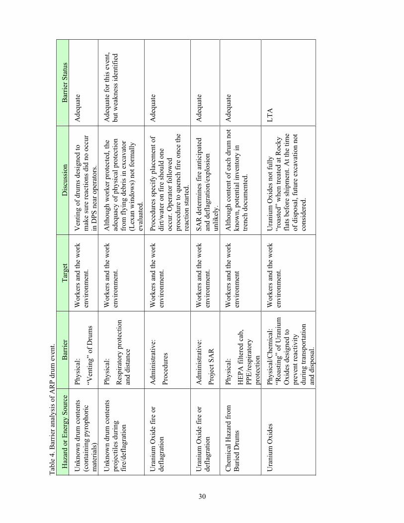
30
Tab
le 4
. B
arri
er a
nal
ysi
s o
f A
RP
dru
m e
ven
t.
Haz
ard
or
En
erg
y S
ou
rce
Bar
rier
Tar
get
Dis
cuss
ion
Bar
rier
Sta
tus
Un
kn
ow
n d
rum
co
nte
nts
(co
nta
inin
g p
yro
ph
ori
c
mat
eria
ls)
Phy
sica
l:
“Ven
tin
g”
of
Dru
ms
Wo
rker
s an
d t
he
wo
rk
env
iro
nm
ent.
Ven
tin
g o
f d
rum
s d
esig
ned
to
mak
e su
re r
eact
ion
s d
id n
o o
ccu
r
in D
PS
nea
r o
per
ato
rs.
Ad
equ
ate
Un
kn
ow
n d
rum
co
nte
nts
pro
ject
iles
du
rin
g
fire
/def
lag
rati
on
Phy
sica
l:
Res
pir
ato
ry p
rote
ctio
n
and
dis
tan
ce
Wo
rker
s an
d t
he
wo
rk
env
iro
nm
ent.
Alt
ho
ug
h w
ork
er p
rote
cted
, th
e
adeq
uac
y o
f p
hy
sica
l p
rote
ctio
n
fro
m f
lyin
g d
ebri
s in
ex
cav
ato
r
(Lex
an w
ind
ow
s) n
ot
form
ally
eval
uat
ed.
Ad
equ
ate
for
this
ev
ent,
bu
t w
eak
nes
s id
enti
fied
Ura
niu
m O
xid
e fi
re o
r
def
lag
rati
on
Ad
min
istr
ativ
e:
Pro
ced
ure
s
Wo
rker
s an
d t
he
wo
rk
env
iro
nm
ent.
Pro
ced
ure
s sp
ecif
y p
lace
men
t o
f
dir
t/w
ater
on
fir
e sh
ou
ld o
ne
occ
ur.
Op
erat
or
foll
ow
ed
pro
ced
ure
to
qu
ench
fir
e o
nce
th
e
reac
tio
n s
tart
ed.
Ad
equ
ate
Ura
niu
m O
xid
e fi
re o
r
def
lag
rati
on
Ad
min
istr
ativ
e:
Pro
ject
SA
R
Wo
rker
s an
d t
he
wo
rk
env
iro
nm
ent.
SA
R d
eter
min
es f
ire
anti
cip
ated
and
def
lag
rati
on
/ex
plo
sio
n
un
lik
ely
.
Ad
equ
ate
Ch
emic
al H
azar
d f
rom
Bu
ried
Dru
ms
Phy
sica
l:
HE
PA
fil
tere
d c
ab,
PP
E/r
esp
irat
ory
pro
tect
ion
Wo
rker
s an
d t
he
wo
rk
env
iro
nm
ent
Alt
ho
ug
h c
on
ten
t o
f ea
ch d
rum
no
t
kn
ow
n, p
ote
nti
al i
nv
ento
ry i
n
tren
ch d
ocu
men
ted
.
Ad
equ
ate
Ura
niu
m O
xid
es
Ph
ysi
cal/
Ch
emic
al:
“Ro
asti
ng
” o
f U
ran
ium
Ox
ides
des
ign
ed t
o
pre
ven
t re
acti
vit
y
du
rin
g t
ran
spo
rtat
ion
and
dis
po
sal.
Wo
rker
s an
d t
he
wo
rk
env
iro
nm
ent.
Ura
niu
m O
xid
es n
ot
full
y
“ro
aste
d”
wh
en t
reat
ed a
t R
ock
y
flat
s b
efo
re s
hip
men
t. A
t th
e ti
me
of
dis
po
sal,
fu
ture
ex
cav
atio
n n
ot
con
sid
ered
.
LT
A
31
6. IDENTIFICATION OF ORGANIZATION AND PROCESS WEAKNESSES
The charter for the investigation tasked the team to evaluate organizational and process
weaknesses. While none of the issues identified in this section constitute a direct cause of the event, they
are included for lessons learned and for project resolution. The ARP organization and processes were
evaluated as they applied to this event only.
6.1 Evaluation of Project Emergency Response Actions
On November 21, 2005, the excavator operator upon acknowledging the drum to be on fire exited
the operational technical procedure, TPR-7420, “ARP - Waste Retrieval,” Section 4.6, Retrieving Waste,
specifically Step 4.6.2, and entered emergency alarm response procedure EAR-246, “ARP — Respond to
Fire.”
The operator initially started to fight the fire with the dust-suppression system. The use of the
dust-suppression system appeared to be ineffective. The operator indicated that the fire appeared to
continue to grow as he sprayed the water. The operator then began placing dirt on top of the fire. After
the initial knock-down of the flames, the operator notified his supervisor of the fire via radio. Flames
continued to come through the initial load of dirt and the operator added additional dirt, apparently
extinguishing the fire. The operator then continued to apply more dirt and water from the
dust-suppression system. The operator estimated that he placed 3 to 5 ft of dirt over the top of the drums.
After notification by the operator, the operations foreman, and shift operations managers contacted
the fire department, initiated a controlled evacuation, and established contact with the shift supervisor.
The shift supervisor determined that no additional protective actions were required, placed the facility in
the warm standby mode, directed operators to flake hoses, and made an Emergency Notification System
announcement. However, the emergency preparedness plan referred to in the emergency alarm response
(EAR) procedure was identified as “inactive” in the contractor Electronic Document Management System
(EDMS). The shift supervisor had a hard copy available for referring to ARP emergency action levels for
determining additional protective actions.
The fire department responded in accordance with their specific ARP requirements for equipment,
time, and personnel. However, upon charging the flaked hoses, water was not immediately available
because of icing in the hose from a previous response. This issue was identified by the project and
requires timely resolution for continued operation.
Based on the information available to project management (i.e., there was a fire in the RE that had
been extinguished as specified in the EAR procedure), the project decided that entering a site Emergency
Action Level was not warranted. It was not until the critique of the event that facility management was
made aware of speculation that a potential explosion might have occurred. The team evaluated this event
and concurred with the project’s initial determination. Insufficient evidence existed to declare the event a
potential explosion; hence, entering a site Emergency Action Level was not warranted.
Other than the problem with ice in the hose as described above, the emergency response actions
taken by the project were timely, compliant, and effective.
32
6.2 Project Safety and Hazards Analysis
The team reviewed the applicable Safety Analysis Report (SAR), Fire Hazards Analysis (FHA),
Health and Safety Plan (HASP), and other project documents to obtain an overall perspective of the
project’s integrated hazards analysis.
6.2.1 Safety Analysis Report Weaknesses
The existing SAR as initially prepared and approved, although weak, met order requirements. The
analysis appears to have been based on previous experience at INL and on physical investigation by
probes of the excavation site. The SAR includes an analysis of drum fire and explosion/deflagration
events. For purposes of incorporating lessons learned, the SAR does not reference many of the drum
fire/explosion events that have occurred in the DOE complex and it is not clear whether the lessons
learned from these events were factored into the analysis performed. At the time that the SAR was
approved, the general consensus in the DOE complex was that a drum explosion from these types of
operations was incredible. The SAR determined a drum explosion as being unlikely.
The hazards from pyrophoric materials and chemicals were considered in the SAR as industrial
hazards and were expected to be implemented through the HASP and safety management programs. The
SAR anticipated pyrophoric material as initiators to fires in the excavation pit; however, the review team
could not identify a specific set of controls for pyrophoric hazards during normal or abnormal operations.
Response to accident situations was expected to be covered in the safety management systems in the form
of a response by the INL Fire Department.
The project has declared a Potential Inadequacy in the Safety Analysis on the fire/explosion event
and is in the Unreviewed Safety Question (USQ) process. Although not directly linked to the fire, the
team identified a number of issues with the SAR that need to be addressed:
Sufficient detail is missing in the SAR on analysis of the actual work process in use to protect
assumptions used as a basis in the analysis.
The focus of the SAR is on fires and deflagrations primarily due to hydrogen. Based on this
investigation, additional analysis of pyrophoric materials would be appropriate.
The assumption that the majority of drums are not intact (and cannot contain hydrogen gas) should
be reanalyzed. The analysis should include the possibility of drum and inner container
pressurization.
The assumption that pyrophoric material is largely oxidized should be reanalyzed.
There is no evidence that the potential effects of intact inner containers were analyzed. Moving
drums with the potential of nonvented inner containers into the DPS should be reanalyzed because
of the potential for reactive events occurring within the DPS during cutting and sorting operations.
The need to use nonsparking tools throughout the process should be reanalyzed.
6.2.1.1 Unreviewed Safety Question Weaknesses. As part of the investigation, the USQ
process was evaluated. In general, the USQ process is rigorous and changes from a multitude of sources
are considered such as changes in process(es), procedures, facility modifications, engineering design files
(EDFs), and others. In the past year, over 1,000 USQs were processed by RWMC/ARP management.
However, no USQs could be identified that were a direct result of encountering intact drums (i.e., drums
33
of a higher degree of integrity) during the excavation, contrary to the conditions evaluated in the SAR.
Additionally, the USQ determination that was performed when the process was changed to open drums in
the DPS was determined to be negative and did not completely capture several scenarios. The SAR and
the DPS operating procedure do not address “containers within containers” in the DPS. No formal safety
documentation was performed to evaluate the possibility of intact drum contents (such as inner sealed
containers, cans, or bags) exploding and creating radiological, chemical, or other industrial hazards
(projectiles, overpressure conditions).
6.2.1.2 Supporting Documents. In addition, RWMC-EDF-240, was used as a basis for the local
evaluation guideline (EG) of 10 psi overpressure. The team conducted an in-depth review of this EDF and
found that the EDF, created in 1983, was technically flawed and the record copy in the company’s EDMS
was not a complete copy. The SAR documents an overpressure condition of 4 psi at 4.7 ft from a drum
explosion/deflagration. The EDF appears to use this value as a design criterion for a drum venting silo.
The EDF goes on to show that overpressure conditions at 18 in. (a distance reasonable for hands-on
processes) are expected to be 33 psi. This is more than three times the EG established in the contractors’
procedures (from DOE-ID Guide 420.D) and would be expected to cause significant injury. This
information was not taken into consideration during the evaluation of the change in process. Further, in
providing a basis for drum explosion/deflagration, the EDF does not discuss the possibility of the drum
contents (such as inner sealed containers, cans, or bags) exploding and creating similar hazards.
6.2.2 Fire Protection
6.2.2.1 Exemption Background. In November 2004, the project obtained DOE Headquarters
approval of exemptions from the fire protection requirements of DOE Order 420.1A, “Facility Safety,”
(now DOE Order 420.1B) and National Fire Protection Association (NFPA) Standard 801, “Standard for
Fire Protection for Facilities Handling Radioactive Materials.” Specifically, the exemptions included
relief from the requirement for installation of fire mains, installation of automatic fire-suppression
systems, and use of noncombustible construction material. The fire protection exemption was
implemented by the project FHA, HAD-266, “Hazards Assessment Document for the Combination Fire
Hazards Analysis and Fire Safety Assessment for the Accelerated Retrieval Project Retrieval Enclosure
(WMF-697).”
The fire protection exemption request is documented through a series of letters among Bechtel
BWXT Idaho, DOE-ID, and DOE Headquarters. These letters identify alternative controls and/or systems
that were determined suitable, and approved, by DOE Headquarters for the RE. Approved controls and/or
systems include:
Operator training on incipient-stage fire suppression using the excavator dust-suppression system
and/or soil
An enhanced initial fire department response, to include an engine and the water tender, six
firefighters, and an on-scene commander
Administrative controls to suspend hazardous operations when the fire department is unable to
provide the enhanced initial response
Large-diameter hose staged in an enclosed trailer
Trained operators to deploy the hose from the ARP to the nearest hydrant
A water tank at the ARP site, which, when combined with the fire department tender, supplies a
minimum of 5,000 gal of water
34
Fabric membranes and insulation meeting the requirements of NFPA 701, “Standard Methods of
Fire Tests for Flame Propagation of Textiles and Fabrics”
Fueled-vehicle storage limited to the excavator(s) and telehandler
Factory Mutual approved less-hazardous (fire-resistive) hydraulic oils in the excavator(s) and
telehandler
A drip pan on the excavator(s) to promptly identify and contain fuel leaks
Fire extinguishers and fire watch during refueling operations
Dry chemical extinguishing systems in each of the DPSs with manual and thermal actuation
Unanswered safety question evaluation of flammable liquids or other materials, not approved or
previously evaluated, found in waste trays
Administrative controls and inspections to ensure limited combustibles in the RE and DPS
Fire watch using cameras covering the general facility areas monitored by the Fire Alarm Center
during off hours
Thermal imaging cameras covering the excavation area
High-sensitivity smoke detection at the HEPA filter inlets
Configuration control for the dry chemical systems and high-sensitivity smoke detection system
Reserve level for the excavator dust-suppression tank
Prohibition of free liquids in the DPS.
6.2.2.2 Exemption Implementation. The approved fire protection exemption requires thermal
imaging cameras covering the excavation area. The approved exemption does not specifically state when
the thermal imaging cameras are required to be monitored. The ARP operating procedures include
specific requirements for monitoring the thermal imaging cameras during excavation. The ARP operating
procedures and HAD-266 do not contain any detail on how the thermal imaging cameras were to be used
to monitor for hot spots, what temperature increase constituted a hot spot, or what actions to take if a hot
spot was identified. Project personnel interviewed considered the thermal imaging cameras to be a tool to
be optionally used at the discretion of Operations personnel during excavation. At the time that the event
occurred and for some amount of time prior to that, the thermal imaging cameras were not routinely used
to monitor for hot spot locations during the excavation process. The team determined that the thermal
imaging cameras were not being used in accordance with the ARP operating procedures.
Based on interviews, at the time of the event, the thermal imaging cameras were not being used,
because they were not considered useful to Operations personnel. Although still available, they were not
routinely used during the excavation process because of equipment failures while moving the camera to
look at different locations in the excavation area. Password protection that activated in 5 minutes of non-
use had been placed on the camera controls in September 2005, making routine use unrealistic and even
more difficult. Additionally, the procedure does not reflect the practice of using the thermal imaging
camera only during backshift times as a method of satisfying the fire watch requirement. This operational
practice was developed in response to the Fire Protection finding from the December 2004 Operational
Readiness Review.
35
Additionally, the DPS fire-suppression system is not designed to suppress a pyrophoric metal fire
and the operating procedure for the DPS does not address pyrophoric metal events in the DPS.
6.2.2.3 Fire Hazard Analysis Weaknesses. While the FHA (HAD-266) identifies the potential
for fires involving waste zone materials and evaluates the consequence of a pit fire regardless of initiator,
the analysis dismisses the potential of pyrophoric metals as a major contributor to a severe fire.
Additionally, HAD-266 states that there is little evidence that the pyrophoric metals buried in the
excavation area are in a form that either will spontaneously ignite or be easily ignited and self-sustaining.
The analysis concludes that while pyrophoric material may be a fire initiator, the presence of this material
is not expected to materially contribute to the final size or severity of a fire. The analysis also assumes
most metal drums are corroded to the point they will not contain hydrogen gas nor will quantities of
flammable liquids that could present an ignitable fuel and air mixture be encountered. Based on AK, the
presence of internal intact containers, and project experience since the start of project operations, the
assumptions in the FHA need to be revised.
6.2.2.4 Emergency Response Procedure. Instructions for immediate actions in the event of a
material fire, electrical fire, pyrophoric material ignition, chemical reaction that ignites other materials, or
ignition of fossil fuel are provided in EAR-246. Section 2.1.5 directs the equipment operator to, if fire is
in the excavation pit and safe to do so, extinguish the fire with dirt and/or dust-suppression spray. The
“ARP – Daily Excavator/Telehandler Checklist” (FRM-191) requires a check to ensure that the
dust-suppression tank is full prior to excavation activities; however, a reserve level for use as a
fire-suppression system has not been implemented as required in the approved fire protection exemption.
Additionally, the team recommends that either the system not be used as a fire-suppression system or a
documented technical basis be completed for its use. The technical basis should include the design
requirements, operability requirements for the system, inspection, testing and maintenance requirements,
and an evaluation of its effectiveness regarding various classes of fires. The results of this technical basis
document should then be incorporated into the emergency response procedures and operator training.
6.2.2.5 Combustible Controls. Both the FHA and the approved fire protection exemption rely
heavily on limited combustible loading in the ARP facility to reduce the likelihood of a fire and to limit
waste involvement in the event of a fire. Although facility inspections for combustible loading are
conducted daily by operations and biweekly by the facility fire protection engineer, specific limits for
combustibles are not implemented. A facility tour on November 29, 2005, by team members indicated
excessive combustibles in the airlocks and retrieval area. Enforcement of combustible loading limits and
controls appears less than adequate and requires more rigor in implementation.
6.2.2.6 Additional Fire Protection. An alternative fire water supply has been implemented to
support retrieval operations. In light of lessons learned from the drum fire event as well as the propane
leak event of November 8, 2005, the alternative fire water supply should be reevaluated to ensure
adequacy, including reasonableness and effectiveness of using an extended hose lay. The evaluation
should address the proper draining of the hose, its use in subfreezing conditions, as well as accessibility to
the hose trailer, fire water tank, and water tender.
6.2.3 Health and Safety Plan Weaknesses
The Health and Safety Plan for the Accelerated Retrieval Project (ICP 2005b), Revision 5, dated
February 2005, identifies the procedures and requirements used to eliminate or minimize health and
safety risks to personnel performing construction and operational tasks within the ARP area at the
RWMC. The HASP contains the assessment and associated mitigation of safety, health, and radiological
hazards for conducting operational activities. The operational activities assessed include the operations
prior to process changes that took place beginning in May 2005. The HASPdoes not assess new safety,
36
health, and radiological hazards as a result of process changes, such as introducing potentially unvented
containers that are within containers into the DPS, cutting and hot work in the DPS, and potential of
projectiles.
6.3 Use of Timely Orders
The project issued several Timely Orders to supplement operating procedures. The Timely Orders
covered such items as controls for numbers and spacing of drums in the RE. The Timely Order
Management Control Procedure (MCP-2984, “Timely Orders to Operators”) requires that information
intended to supplement operating procedures should be promptly incorporated into the appropriate
procedure. One of the Timely Orders had been in place for over 6 months and two others had been in
place for over 2 months. Additionally, the team found no evidence that actions were being taken to
incorporate the Timely Orders into procedures.
6.4 Procedure Inadequacies
The team reviewed the operating procedures in use for the excavation and packaging process and
noted the following areas where they did not contain sufficient detail:
Specifics of when/how to monitor using the thermal imaging camera, what indications constitute a
hot spot, and what actions to take when a hot spot was identified were not contained in project
procedures
For drum venting, there is no time delay or monitoring to detect reactions in the drums after
venting and prior to transfer into the DPS
The procedure does not address actions for known hazardous conditions in the DPS (e.g., finding
sealed containers within the drum or other containers, observing sparking/pyrophoric reactions, and
finding roaster oxides.
6.5 Project History and Potential Significant Events Identified by the Investigation Team
To identify additional potential organizational and process weaknesses, the team reviewed the
project history. The timelines in Figures 19 and 20 outline what the team considered to be significant
events relative to this fire. The events that indicate organizational and/or process weaknesses are
discussed in more detail in the subsequent pages of the report. If the project had conducted more in-depth
evaluation of some of these events when they occurred, the project might have identified the increased
potential for a drum deflagration. However, the team concludes that even if the process weaknesses had
been corrected before opening this drum, the drum would still have undergone a rapid pyrophoric reaction
when opened.
6.5.1 Timeline Analysis
6.5.1.1 Discovery of Intact Drums. At the start of operations in January 2005, the initial
uncovering of drums revealed a significant quantity of “intact” drums. In SAR-4-K-3,
Paragraph 3.3.2.1.3.1, “Waste Container Condition,” it states that waste was generally disposed of in the
SDA in 55-gal metal drums and metal, wood, and cardboard boxes, and that the drums are likely to be
badly damaged. In addition, early retrieval efforts performed in the 1970s and analysis of corrosion rates
for drums indicated that few if any drums will be found intact. Actual waste retrieved from Pit 9 in 2003
as part of the Glovebox Excavator Method Project showed that waste drums had completely corroded.
37
Paragraph 3.3.2.3, “Hazard Evaluation,” of SAR-4-K-3 carries this assumption forward in the
evaluation of Hazard 3.g, “Radioactive Materials and Hazardous Chemicals.” Explosions/deflagrations,
stating that most of the buried metal drums have corroded to the point that they will not contain hydrogen
gas and that while some drums might have maintained structural integrity, the frequency that an intact
drum could be found, contain explosive levels of hydrogen, and be ignited is unlikely.
The project Safety Analysis personnel who were interviewed indicated that although the drums
were intact enough to still hold the waste, few if any of the drums were considered intact enough to
contain any significant hydrogen. No formal evaluation was performed that supported the project
assumptions.
6.5.1.2 Roaster Oxide Excavation. In March 2005, the excavator began to extract drums with
“sparkling material” identified as “roaster oxides” (ROs). During interviews, employees described this
event as being “within the operational envelope.” SAR-4-K-3, Paragraph 3.3.2.3, “Hazard Evaluation,”
Hazard 3.f., “Radioactive Materials and Hazardous Chemicals – Fires,” states that pyrophoric metals are
present in massive form and do not pose a fire hazard. Specifically, small quantities of the nonoxidized
forms of plutonium or uranium could be exposed through the excavation process and the potential for a
fire involving pyrophoric material is anticipated; however, it was considered unlikely that a pyrophoric
fire would propagate. Roaster oxides also are clearly identified in the project AK and mapped by grid
coordinates in the Retrieval Area.
The first drum extracted and identified as containing ROs on March 22, 2005, was packaged out of
the DPS and moved to segregated storage. A second drum was extracted on March 23, 2005, and was
emptied into three trays, mixed with the excavator bucket, and exposed to the air in an apparent attempt to
complete oxidation. In both these cases, the procedures do not specifically address the operations
performed and the handling of ROs and other “sparkling material.”
6.5.1.3 Contract Transition. During contract transition, CWI performed specific reviews of the
safety analysis and the radiological controls used in ARP operations. A number of concerns were
identified and work was halted for nearly 2 and a half months. The majority of these concerns were with
the radiological controls being used and led to a redesign of the operation and retraining of personnel. The
Safety Analysis review concluded that the ARP SAR is compliant with 10 CFR 830 and DOE-STD-3009,
Change Notice No. 2. The review also concluded that the facility appeared to be operating within the
bounds of the SAR with appropriate controls in place for protection of the public and the worker. Some
issues were identified during the review at contract transition. Short summaries of the issues are listed
below. Additional detail is provided in Appendix C.
A concern exists that future operations might not be adequately bounded (i.e., the assumed source
term might not be reasonably bounding for all cases). There is also a concern that system engineers
do not have a formal program for periodic verification of Authorization Basis assumptions.
The stacking of large quantities of trench material outside the trench is not addressed explicitly (or
implicitly) in the SAR.
The ventilation system for the ARP is identified as Defense in Depth (DiD), which might be
contrary to DNFSB Recommendation 2004-2.
The current SAR will require significant changes to authorize the improved methodologies
(e.g., use of the DPS to open intact drums, sorting tables) proposed under this contract (Safety
Management Programs).
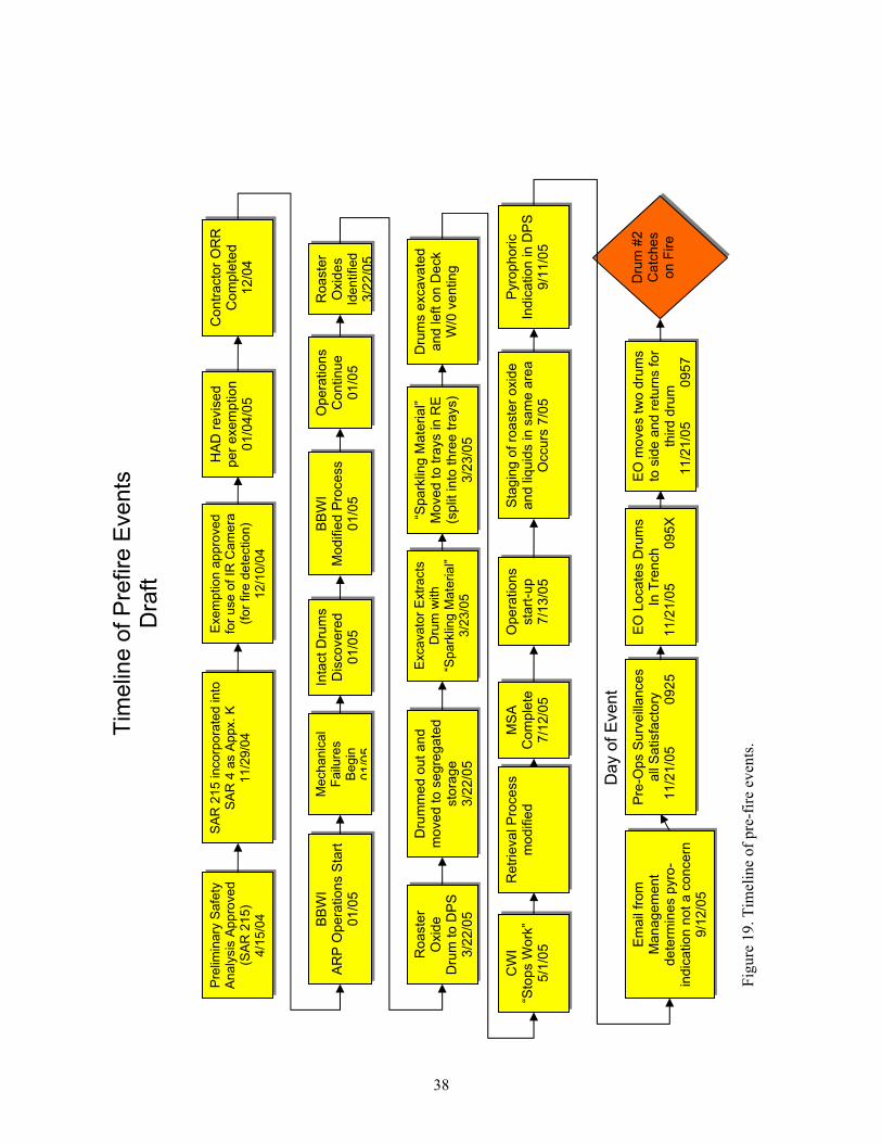
38
Fig
ure
19
. T
imel
ine
of
pre
-fir
e ev
ents
.
Tim
elin
e o
f P
refire
Events
D
raft
Pre
limin
ary
Safe
ty
Analy
sis
Appro
ved
(SA
R 2
15)
4/1
5/0
4
SA
R 2
15 incorp
ora
ted into
S
AR
4 a
s A
ppx.
K
11/2
9/0
4
Exem
ptio
n a
pp
roved
for
use o
f IR
Cam
era
(f
or
fire
dete
ction)
12/1
0/0
4
HA
D r
evis
ed
p
er
exe
mp
tio
n
01
/04
/05
Co
ntr
acto
r O
RR
C
om
ple
ted
12
/04
BB
WI
Mo
difie
d P
roce
ss
01
/05
Inta
ct
Dru
ms
Dis
co
ve
red
01
/05
BB
WI
AR
P O
pe
ratio
ns S
tart
0
1/0
5
Op
era
tio
ns
Co
ntin
ue
01
/05
Mechanic
al
Failu
res
Begin
01/0
5
Ro
aste
rO
xid
es
Identified
3/2
2/0
5
Exca
va
tor
Extr
acts
D
rum
with
“Spark
ling M
ate
rial”
3/2
3/0
5
Dru
mm
ed
ou
t a
nd
mo
ve
d t
o s
eg
reg
ate
d
sto
rag
e3
/22
/05
Ro
aste
rO
xid
e
Dru
m t
o D
PS
3
/22
/05
“Sp
ark
ling
Ma
teri
al”
M
ove
d t
o t
rays in
RE
(s
plit
in
to t
hre
e t
rays)
3/2
3/0
5
Dru
ms e
xca
va
ted
a
nd
le
ft o
n D
eck
W/0
ve
ntin
g
CW
I“S
top
s W
ork
” 5
/1/0
5
Re
trie
va
l P
roce
ss
mo
difie
dO
pe
ratio
ns
sta
rt-u
p7
/13
/05
Pyro
ph
oric
Ind
ica
tio
n in
DP
S
9/1
1/0
5
MS
AC
om
ple
te7
/12
/05
Sta
gin
g o
f ro
aste
r o
xid
e
an
d liq
uid
s in
sa
me
are
a
Occu
rs 7
/05
Pre
-Op
s S
urv
eill
an
ce
s
all
Sa
tisfa
cto
ry
11
/21
/05
0
92
5
EO
Lo
ca
tes D
rum
s
In T
ren
ch
1
1/2
1/0
5
0
95
X
Em
ail
fro
m
Ma
na
ge
me
nt
de
term
ine
s p
yro
- in
dic
atio
n n
ot
a c
on
ce
rn
9/1
2/0
5
Dru
m #
2
Ca
tch
es
on
Fir
e
EO
mo
ve
s t
wo
dru
ms
to s
ide
an
d r
etu
rns f
or
thir
d d
rum
1
1/2
1/0
5
0
95
7
Day o
f E
vent
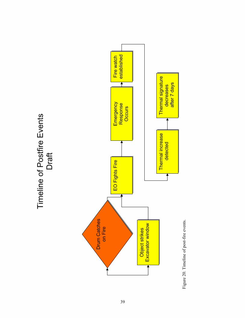
39
Fig
ure
20
. T
imel
ine
of
po
st-f
ire
even
ts.
Tim
elin
e o
f P
ostf
ire
Eve
nts
D
raft
EO
Fig
hts
Fire
Em
erg
ency
Response
Occu
rs
Fire w
atc
he
sta
blis
he
d
Therm
al in
cre
ase
de
tecte
d
Dru
m C
atc
hes
on F
ire
Therm
al sig
natu
re
de
cre
ase
s a
fte
r 7
da
ys
Obje
ct
str
ikes
Excavato
r w
indow
40
A management self assessment (MSA) was performed before restarting ARP operations after the
CWI transition. Since an MSA was performed, the Hazard Review Board process was not used. The
assessment plan for the MSA primarily concentrated on the changes to the process and took credit for
prior readiness reviews. The team did not see evidence that all criteria of the MSA assessment plan had
been completed. Specifically, there is no evidence that the negative USQ screen on the process change
was reviewed for adequacy. This is a missed opportunity for identifying the new hazards introduced by
opening up drums in the DPS.
6.5.1.4 Potential Pyrophoric Indications in the DPS. On September 11, 2005, while
performing hot work operations (drum opening with either a hole saw and/or sawzall) on a “spider” type
container in the DPS, there was sparking between the saw and the container. After review of the tape by
the team members, the team concluded that this was very likely an indication of pyrophoric material or
other reactive metal event, most likely initiated while cutting through an inner container in the “spider.”
There is some indication that silver may have been present and a silver compound could have reacted
during the cutting process. The retrieval specialist operating the CCTV had recognized the sparking
condition and initiated a review of the tape by project management, the fire protection engineer, and the
industrial safety professional. They concluded that it was ordinary industrial metal-to-metal sparking. No
formal evaluation was documented on this event. Figure 21 is a process weakness cause and effect
diagram of the ARP.
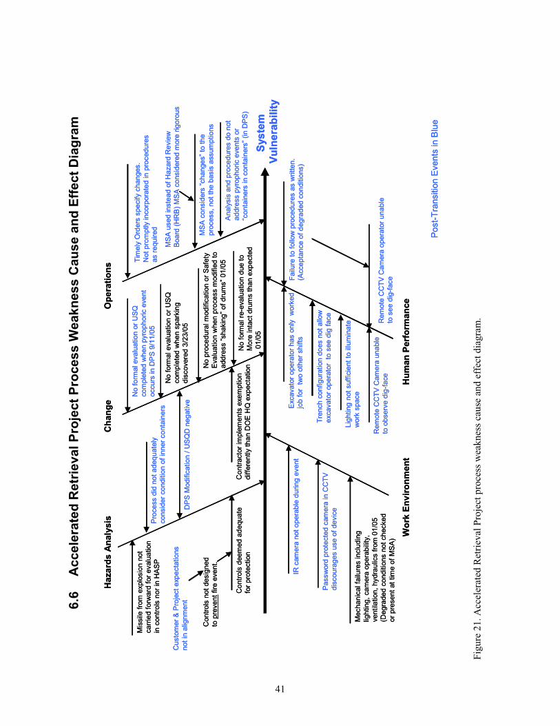
41
6.6
A
cc
ele
rate
d R
etr
iev
al
Pro
jec
t P
roc
es
s W
ea
kn
es
s C
au
se
an
d E
ffe
ct
Dia
gra
m
Fig
ure
21
. A
ccel
erat
ed R
etri
eval
Pro
ject
pro
cess
wea
kn
ess
cau
se a
nd
eff
ect
dia
gra
m.
Sys
tem
Vu
lne
rab
ilit
y
Op
era
tio
ns
Ch
an
ge
Hu
man
Perf
orm
an
ce
Ha
za
rds
An
aly
sis
Wo
rk E
nv
iro
nm
en
t
Contr
ols
not
desig
ned
to p
revent
fire
eve
nt.
Mis
sile
fro
m e
xplo
sio
n n
ot
carr
ied f
orw
ard
for
evalu
atio
n
in c
ontr
ols
nor
in H
AS
P
Contr
acto
r im
ple
ments
exem
ption
diffe
rently t
ha
n D
OE
HQ
expecta
tion
Contr
ols
deem
ed a
deq
uate
for
pro
tection
Custo
mer
& P
roje
ct
exp
ecta
tions
not
in a
lignm
ent
No f
orm
al evalu
atio
n o
r U
SQ
com
ple
ted w
he
n s
park
ing
dis
covere
d 3
/23/0
5
No f
orm
al evalu
atio
n o
r U
SQ
com
ple
ted w
he
n p
yro
ph
oric e
vent
occurs
in D
PS
9/1
1/0
5
No p
roced
ura
l m
odific
ation o
r S
afe
ty
Evalu
atio
n w
he
n p
rocess m
odifie
d t
o
addre
ss “
shakin
g”
of
dru
ms”
01/0
5 Tim
ely
Ord
ers
specify c
hanges.
Not
pro
mptly incorp
ora
ted in p
rocedure
s
as r
equired
MS
A c
onsid
ers
“changes”
to t
he
pro
cess,
not
the b
asis
assum
ptions
Analy
sis
and p
roced
ure
s d
o n
ot
addre
ss p
yro
ph
oric e
vents
or
“conta
iners
in c
onta
iners
”(in D
PS
)N
o f
orm
al re
-evalu
atio
n d
ue t
o
More
inta
ct
dru
ms t
han e
xp
ecte
d
01/0
5
Mecha
nic
al fa
ilure
s inclu
din
g
lightin
g,
cam
era
ope
rab
ility
,
ventila
tion,
hydra
ulic
s f
rom
01/0
5
(Degra
de
d c
onditio
ns n
ot
checked
or
pre
sent
at
tim
e o
f M
SA
)
Rem
ote
CC
TV
Cam
era
unable
to o
bserv
e d
ig-f
ace
Lig
hting n
ot
suff
icie
nt
to illu
min
ate
work
space
Tre
nch c
onfigura
tion d
oes n
ot
allo
w
excavato
r op
era
tor
to s
ee d
ig f
ace
Passw
ord
pro
tecte
d c
am
era
in C
CT
V
dis
coura
ges u
se o
f de
vic
e
Post-
Tra
nsitio
n E
vents
in B
lue
IR c
am
era
not
opera
ble
during e
vent
Pro
cess d
id n
ot
ad
eq
uate
ly
consid
er
conditio
n o
f in
ner
conta
iners
MS
A u
sed inste
ad o
f H
azard
Re
vie
w
Board
(H
RB
) M
SA
consid
ere
d m
ore
rig
oro
us
Excavato
r o
pera
tor
has o
nly
w
ork
ed
job f
or
tw
o o
ther
shifts
Rem
ote
CC
TV
Cam
era
opera
tor
unable
to s
ee d
ig-f
aceF
ailu
re t
o f
ollo
w p
roce
dure
s a
s w
ritt
en.
(Accepta
nce o
f d
egra
ded c
on
ditio
ns)
DP
S M
odific
ation /
US
QD
negative
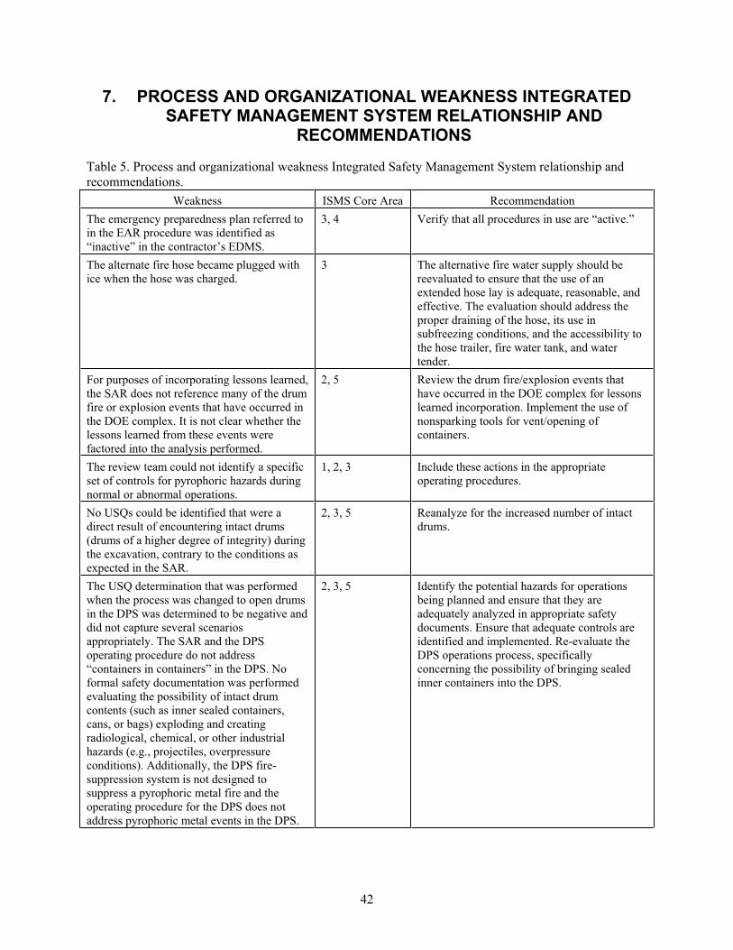
42
7. PROCESS AND ORGANIZATIONAL WEAKNESS INTEGRATED SAFETY MANAGEMENT SYSTEM RELATIONSHIP AND
RECOMMENDATIONS
Table 5. Process and organizational weakness Integrated Safety Management System relationship and
recommendations.
Weakness ISMS Core Area Recommendation
The emergency preparedness plan referred to
in the EAR procedure was identified as
“inactive” in the contractor’s EDMS.
3, 4 Verify that all procedures in use are “active.”
The alternate fire hose became plugged with
ice when the hose was charged.
3 The alternative fire water supply should be
reevaluated to ensure that the use of an
extended hose lay is adequate, reasonable, and
effective. The evaluation should address the
proper draining of the hose, its use in
subfreezing conditions, and the accessibility to
the hose trailer, fire water tank, and water
tender.
For purposes of incorporating lessons learned,
the SAR does not reference many of the drum
fire or explosion events that have occurred in
the DOE complex. It is not clear whether the
lessons learned from these events were
factored into the analysis performed.
2, 5 Review the drum fire/explosion events that
have occurred in the DOE complex for lessons
learned incorporation. Implement the use of
nonsparking tools for vent/opening of
containers.
The review team could not identify a specific
set of controls for pyrophoric hazards during
normal or abnormal operations.
1, 2, 3 Include these actions in the appropriate
operating procedures.
No USQs could be identified that were a
direct result of encountering intact drums
(drums of a higher degree of integrity) during
the excavation, contrary to the conditions as
expected in the SAR.
2, 3, 5 Reanalyze for the increased number of intact
drums.
The USQ determination that was performed
when the process was changed to open drums
in the DPS was determined to be negative and
did not capture several scenarios
appropriately. The SAR and the DPS
operating procedure do not address
“containers in containers” in the DPS. No
formal safety documentation was performed
evaluating the possibility of intact drum
contents (such as inner sealed containers,
cans, or bags) exploding and creating
radiological, chemical, or other industrial
hazards (e.g., projectiles, overpressure
conditions). Additionally, the DPS fire-
suppression system is not designed to
suppress a pyrophoric metal fire and the
operating procedure for the DPS does not
address pyrophoric metal events in the DPS.
2, 3, 5 Identify the potential hazards for operations
being planned and ensure that they are
adequately analyzed in appropriate safety
documents. Ensure that adequate controls are
identified and implemented. Re-evaluate the
DPS operations process, specifically
concerning the possibility of bringing sealed
inner containers into the DPS.
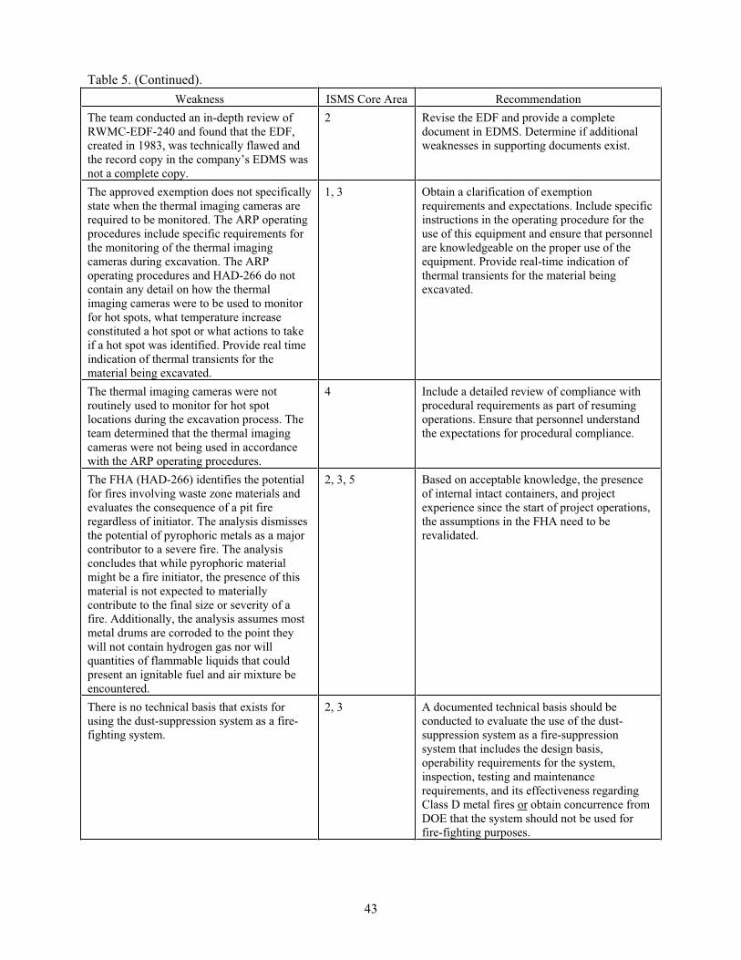
Table 5. (Continued).
43
Weakness ISMS Core Area Recommendation
The team conducted an in-depth review of
RWMC-EDF-240 and found that the EDF,
created in 1983, was technically flawed and
the record copy in the company’s EDMS was
not a complete copy.
2 Revise the EDF and provide a complete
document in EDMS. Determine if additional
weaknesses in supporting documents exist.
The approved exemption does not specifically
state when the thermal imaging cameras are
required to be monitored. The ARP operating
procedures include specific requirements for
the monitoring of the thermal imaging
cameras during excavation. The ARP
operating procedures and HAD-266 do not
contain any detail on how the thermal
imaging cameras were to be used to monitor
for hot spots, what temperature increase
constituted a hot spot or what actions to take
if a hot spot was identified. Provide real time
indication of thermal transients for the
material being excavated.
1, 3 Obtain a clarification of exemption
requirements and expectations. Include specific
instructions in the operating procedure for the
use of this equipment and ensure that personnel
are knowledgeable on the proper use of the
equipment. Provide real-time indication of
thermal transients for the material being
excavated.
The thermal imaging cameras were not
routinely used to monitor for hot spot
locations during the excavation process. The
team determined that the thermal imaging
cameras were not being used in accordance
with the ARP operating procedures.
4 Include a detailed review of compliance with
procedural requirements as part of resuming
operations. Ensure that personnel understand
the expectations for procedural compliance.
The FHA (HAD-266) identifies the potential
for fires involving waste zone materials and
evaluates the consequence of a pit fire
regardless of initiator. The analysis dismisses
the potential of pyrophoric metals as a major
contributor to a severe fire. The analysis
concludes that while pyrophoric material
might be a fire initiator, the presence of this
material is not expected to materially
contribute to the final size or severity of a
fire. Additionally, the analysis assumes most
metal drums are corroded to the point they
will not contain hydrogen gas nor will
quantities of flammable liquids that could
present an ignitable fuel and air mixture be
encountered.
2, 3, 5 Based on acceptable knowledge, the presence
of internal intact containers, and project
experience since the start of project operations,
the assumptions in the FHA need to be
revalidated.
There is no technical basis that exists for
using the dust-suppression system as a fire-
fighting system.
2, 3 A documented technical basis should be
conducted to evaluate the use of the dust-
suppression system as a fire-suppression
system that includes the design basis,
operability requirements for the system,
inspection, testing and maintenance
requirements, and its effectiveness regarding
Class D metal fires or obtain concurrence from
DOE that the system should not be used for
fire-fighting purposes.
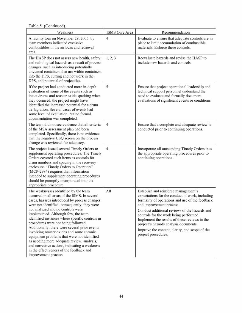
Table 5. (Continued).
44
Weakness ISMS Core Area Recommendation
A facility tour on November 29, 2005, by
team members indicated excessive
combustibles in the airlocks and retrieval
area.
4 Evaluate to ensure that adequate controls are in
place to limit accumulation of combustible
materials. Enforce these controls.
The HASP does not assess new health, safety,
and radiological hazards as a result of process
changes, such as introducing potentially
unvented containers that are within containers
into the DPS, cutting and hot work in the
DPS, and potential of projectiles.
1, 2, 3 Reevaluate hazards and revise the HASP to
include new hazards and controls.
If the project had conducted more in-depth
evaluation of some of the events such as
intact drums and roaster oxide sparking when
they occurred, the project might have
identified the increased potential for a drum
deflagration. Several cases of events had
some level of evaluation, but no formal
documentation was completed.
5 Ensure that project operational leadership and
technical support personnel understand the
need to evaluate and formally document
evaluations of significant events or conditions.
The team did not see evidence that all criteria
of the MSA assessment plan had been
completed. Specifically, there is no evidence
that the negative USQ screen on the process
change was reviewed for adequacy.
4 Ensure that a complete and adequate review is
conducted prior to continuing operations.
The project issued several Timely Orders to
supplement operating procedures. The Timely
Orders covered such items as controls for
drum numbers and spacing in the recovery
enclosure. “Timely Orders to Operators”
(MCP-2984) requires that information
intended to supplement operating procedures
should be promptly incorporated into the
appropriate procedure.
4 Incorporate all outstanding Timely Orders into
the appropriate operating procedures prior to
continuing operations.
The weaknesses identified by the team
occurred in all areas of the ISMS. In several
cases, hazards introduced by process changes
were not identified; consequently, they were
not analyzed and no controls were
implemented. Although few, the team
identified instances where specific controls in
procedures were not being followed.
Additionally, there were several prior events
involving roaster oxides and some chronic
equipment problems that were not identified
as needing more adequate review, analysis,
and corrective actions, indicating a weakness
in the effectiveness of the feedback and
improvement process.
All Establish and reinforce management’s
expectations for the conduct of work, including
formality of operations and use of the feedback
and improvement process.
Conduct additional reviews of the hazards and
controls for the work being performed.
Implement the results of these reviews in the
project’s hazards analysis documents.
Improve the content, clarity, and scope of the
project procedures.
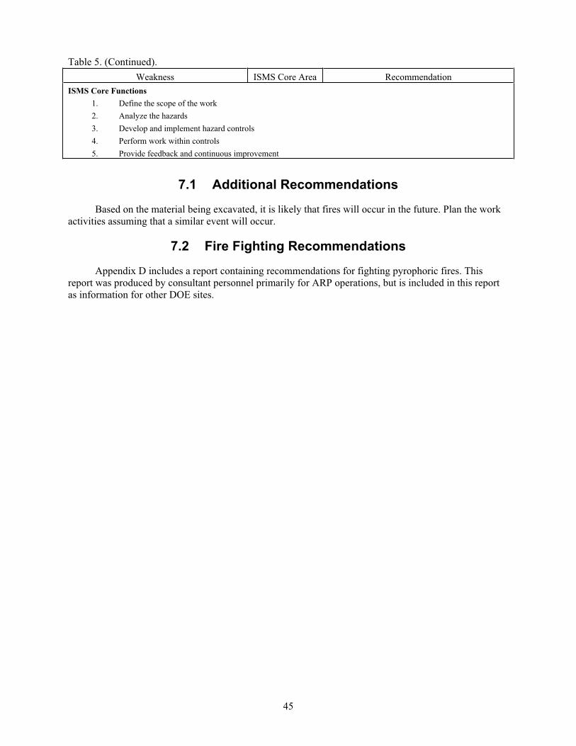
Table 5. (Continued).
45
Weakness ISMS Core Area Recommendation
ISMS Core Functions
1. Define the scope of the work
2. Analyze the hazards
3. Develop and implement hazard controls
4. Perform work within controls
5. Provide feedback and continuous improvement
7.1 Additional Recommendations
Based on the material being excavated, it is likely that fires will occur in the future. Plan the work
activities assuming that a similar event will occur.
7.2 Fire Fighting Recommendations
Appendix D includes a report containing recommendations for fighting pyrophoric fires. This
report was produced by consultant personnel primarily for ARP operations, but is included in this report
as information for other DOE sites.
46
8. REFERENCES
BNFL Inc., 2003, Advanced Mixed Waste Treatment Project: Investigation and Root Cause Analysis of
the Fire in the TRU Waste Drum, RCA-03-007, Rev. 1, September 24, 2003.
DOE, 1994, “Primer on Spontaneous Heating and Pyrophoricity,” DOE-HDBK-1081-94,
U.S. Department of Energy.
DOE O 420.1A, 2002, “Facility Safety,” U.S. Department of Energy.
EAR-246, 2005, “ARP – Respond to Fire,” Rev. 2, Idaho National Laboratory, Idaho Cleanup Project.
EDF-4478, 2005, “Waste Inventory of the Described Area within Pit 4 for the Accelerated Retrieval
Project within the Radioactive Waste Management Complex,” Rev. 3, Idaho National Laboratory,
Idaho Cleanup Project.
EDF-5943, 2005, “Identifying Characteristics of Rocky Flats Plant Depleted Uranium Roaster Oxide
Waste,” Rev. 0, Idaho National Laboratory, Idaho Cleanup Project.
Haar, D. H., 2005, “Central Characterization Project Acceptable Knowledge Summary Report for A
Described Area in Pit 4 at the Idaho National Laboratory: Transuranic Waste Stream
ID-SDA-PIT4-DEBRIS, ID-SDA-PIT4-SLUDGE, ID-SDA-PIT4-SOIL,” CCP-AK-INK-001,
Revision 1, April 15, 2005.
HAD-266, 2005, “Hazards Assessment Document for the Combination Fire Hazards Analysis and Fire
Safety Assessment for the Accelerated Retrieval Project Retrieval Enclosure (WMF-697),” Rev. 6,
Idaho National Laboratory, Idaho Cleanup Project.
ICP, 2005a, Critique Report: ARP Drum Fire/Apparent Explosion in Retrieval Enclosure November 21,
2005, Idaho National Laboratory, Idaho Cleanup Project, November 21, 2005, 1230.
ICP, 2005b, Health and Safety Plan for the Accelerated Retrieval Plan, ICP/EXT-04-00209, Rev. 5,
Idaho National Laboratory, Idaho Cleanup Project, February 2005.
McIlwain, Beth A., 2005, Field Sampling Plan for the Accelerated Retrieval Project I,ICP/EXT-04-00516, Revision 4, Idaho National Laboratory, Idaho Cleanup Project.
MCP-2984, 1999, “Chapter XV-Timely Orders to Operators,” Rev. 1, Manual 9-Operations, Idaho
National Engineering and Environmental Laboratory.
Molecke, M. A., 1979, “Gas Generation from Transuranic Waste Degradation,” SAND79-0911C,
presentation at the Materials Research Society International Symposium on the Scientific Basis for
Nuclear Waste Management, Boston Massachusetts, November 1979.
NFPA 701-04, 2004, “Standard Methods of Fire Tests for Flame Propagation of Textiles and Films,”
National Fire Protection Association.
NFPA 801, 2003, “Facilities Handling Radioactive Materials,” National Fire Protection Association.
TPR-7420, 2005, “ARP – Waste Retrieval,” Rev. 15, Idaho National Laboratory, Idaho Cleanup Project.
47
UNC Nuclear Industries, 1954, “Uranium Fire Experience,” HAN-64841, Atomic Energy Commission,
September 17, 1954.
Zerwekh, A., 1979, “Gas Generated from Radiolytic Attack of TRU-Contaminated Hydrogenous Waste,”
LA-7674-MS, June 1979.
9. DOCUMENTS REVIEWED
BBWI, 2004, Occurrence Report ID-BBWI-RWMC-2004-0012, “CORR Identifies Pre-Start Finding
Regarding Full Implementation of ARP Firewatch,” February 5, 2005.
BNFL Inc., 2003, Advanced Mixed Waste Treatment Project: Investigation and Root Cause Analysis of the Fire in the TRU Waste Drum, RCA-03-007, Rev. 1, September 24, 2003.
DOE-CBFO, 1987, “Waste Drum Fire Propagation at the Waste Isolation Pilot Plant,” DOE/WIPP-87-
005, U.S. Department of Energy Carlsbad Field Office.
DOE, 1994, “Primer on Spontaneous Heating and Pyrophoricity,” DOE-HDBK-1081-94,
U.S. Department of Energy, December 1994.
EAR-246, 2005, “ARP – Respond to Fire,” Rev. 2, Idaho National Laboratory, Idaho Cleanup Project,
January 6, 2005.
EDF-4478, 2005, “Waste Inventory of the Described Area within Pit 4 for the Accelerated Retrieval
Project within the Radioactive Waste Management Complex,” Rev. 3, Idaho National Laboratory,
Idaho Cleanup Project.
EDF-5943, 2005, “Identifying Characteristics of Rocky Flats Plant Depleted Uranium Roaster Oxide
Waste,” Rev. 0, Idaho National Laboratory, Idaho Cleanup Project.
FRM-191, “ARP – Daily Excavator/Telehandler Checklist,” Rev. 10, November 7, 2005.
Haar, D. H., 2005, “Central Characterization Project Acceptable Knowledge Summary Report for A
Described Area in Pit 4 at the Idaho National Laboratory: Transuranic Waste Stream
ID-SDA-PIT4-DEBRIS, ID-SDA-PIT4-SLUDGE, ID-SDA-PIT4-SOIL,” CCP-AK-INK-001,
Revision 1, April 15, 2005.
HAD-266, 2004, “Fire Hazards Analysis for the Accelerated Retrieval Project at a Described Area within
Pit 4,” Rev. 4, Idaho National Engineering and Environmental Laboratory, Idaho Completion
Project.
ICP, 2005, Fire Department Pre-Incident Plan, “WMF-697 Subsurface Disposal Area Retrieval Enclosure
Site,” January 2005.
ICP, 2005, Fire Alarm Center Daily Activity Log, November 21, 2005 through November 27, 2005.
ICP, 2005, Health and Safety Plan for the Accelerated Retrieval Plan, ICP/EXT-04-00209, Rev. 5, Idaho
National Laboratory, Idaho Cleanup Project, February 2005.
ICP, 2006, RWMC Facility Fire Impairment Logbook.
48
MCP-1777, “RWMC Fire Protection Program,” Rev. 10, May 15, 2005.
MCP-4186, 2004, “Video Firewatch Monitoring,” Rev. 0, November 16, 2004.
Molecke, M. A., 1979, “Gas Generation from Transuranic Waste Degradation,” SAND79-0911C,
presentation at the Materials Research Society International Symposium on the Scientific Basis for
Nuclear Waste Management, Boston Massachusetts, November 1979.
Preussner, B., 2004, “Project Process Overview,” July 2004, an overview of the project for Accelerated
Retrieval Project within Pit 4.
TPR-7420, 2005, “ARP – Waste Retrieval,” Rev. 15, Idaho National Laboratory, Idaho Cleanup Project.
TPR-7420, 2005, “ARP – Waste Retrieval,” Rev. 16, December 1, 2005.
Zerwekh, A., 1979, “Gas Generated from Radiolytic Attack of TRU-Contaminated Hydrogenous Waste,”
LA-7674-MS, June 1979.
Zima, G. E., 1961, “Some Fire and Fission Product Release Possibilities for Discharged Fuel Slugs,”
HW-68409, Hanford, February 7, 1961.
49
Appendix A
Biographical Information on the Team

50
51
Appendix A
Biographical Information on the Team
KENNETH O. BAILEY
Mr. Bailey is a Senior Operator with the Drum Package System, where targeted nuclear waste is sorted
and segregated that was excavated from Pit #4. In this position he also operates compressors, breathing air
and plant air. He is qualified to operate ARP facility off gas, heating and ventilation system. Operate
drum handlers, one-ton monorail hoist, and Fissile Material Monitor. He handles liquid nitrogen dewars
and fills Non Destructive Assay dewars with liquid nitrogen. His job responsibilities also include
recording data on plant forms and round sheets. Mr. Bailey is also trained to perform RCRA inspections
and track waste drums. Previously he was a Job Site Supervisor/Construction Coordinator from April
2004 to October 2004 where he supervised the deactivation, decommission and demolition of thirteen
buildings at the INEEL TAN site. This involved supervising and coordinating a crew of 25 (heavy
equipment operators, laborers, welders, carpenters) to safely demolish Department of Energy buildings
and dispose of debris according to EPA regulations. He is Certified as a Senior Operator for the TAN
Utilities, a State of Idaho Apprentice Certification for Senior Operator, Waste Experimental Reduction
Facility, Senior Operator Certification for Nuclear Fuel Handling, and Operator Certification for Fluorinel
Dissolution.
KEN BREWER
Mr. Brewer obtained his BS degree in Chemistry from Albertson College of Idaho in 1985, and his
Masters of Science in Chemistry from the University of Idaho in 1992. He has over 20 years experience
in analytical chemistry, nuclear process support and process chemistry, nuclear waste treatment, and
fission product/actinide separations. Mr. Brewer has numerous publications in these areas and holds six
patents all related to waste treatment and/or radionuclide separations. He also has eight years experience
in Nuclear Facility Operations and Management. He is currently the manager of the INTEC Analytical
Laboratories Department and is the Nuclear Facility Manager for two nuclear facilities.
BRUCE CAMPBELL
Mr. Campbell is a Senior Fire Protection Engineer with over 28 years of fire protection engineering
experience (BS Fire Protection/Industrial Safety, June 1977). He is the Director of the Denver Office for
Hughes Associates, Inc. His experience includes over 8 years as a senior loss control engineer for a highly
protected risk insurance carrier where he conducted surveys of large industrial facilities and 19 years at a
large nuclear facility where he was in charge of the overall fire protection program. In these positions,
Mr. Campbell coordinated and participated in several high visibility fire investigations, operational
readiness reviews, the commissioning of a large variety of fire protection systems, assessments of fire
protection programs, coordination and implementation of a fire protection program and design authority
for numerous fire protection systems. Mr. Campbell provides expert support in legal matters relating to
fire alarm, automatic sprinkler systems and loss control. He also prepares fire hazards analysis reports for
several DOE Sites, including the Idaho National Laboratory and the Los Alamos National Laboratory.
At the Rocky Flats Environmental Technology Site (REETS), Mr. Campbell was involved with all
aspects of the fire protection program for his entire tenure. Prior to the final closure of the project he was
a consultant to Kaiser-Hill, LLC and acted in the capacity of the Authority Having Jurisdiction in all
matters relating to fire protection. He had programmatic responsibility for the fire protection programs
52
(Fire Department, Fire Prevention, Fire Protection Engineering, Inspection, Testing and Maintenance) at
the Site.
TARYN COUCHMAN
Ms. Couchman is the DOE-Idaho Fire Protection Engineer for the Idaho National Laboratory Site. She
has responsibility for oversight of the contractor Fire Protection Programs, Fire and Life Safety Systems
Programs, and Fire Department Operations. Ms. Couchman is DNFSB Recommendation 93 3 qualified in
Fire Protection. She holds a bachelors degree in Fire Protection and Safety Engineering Technology from
Oklahoma State University. Prior to joining the Department of Energy, Ms. Couchman was the lead Fire
Protection Engineer at the Idaho National Engineering and Environmental Laboratory for the Test
Reactor Area, now called the Reactor Technology Complex, which includes the Advanced Test Reactor.
In this position, Ms. Couchman provided fire protection engineering support to line management with
applied knowledge of fire safety, fire suppression and detection systems, fire hazards analysis, and fire
safety assessments.
STEVEN CROWE
Mr. Crowe has 27 years of experience in the safe management of nuclear materials, decommissioning and
demolition (D&D) of nuclear facilities, operation and licensing of nuclear facilities, and disposal of
hazardous chemicals. He also provides consulting services in the areas of readiness preparations and
assessments as well as operational nuclear safety. Prior to moving to Oak Ridge, he was the ESH&Q
Manager for Material Stewardship at the Rocky Flats Environmental Technology Site (RFETS) in
Golden, Colorado. He managed a team of up to 150 waste management, safety, environmental,
radiological control, nuclear safety, oversight and industrial safety professionals. He was the team leader
for the Interagency Agreement Tank uptake investigation. Mr. Crowe was a Senior Reactor Safety
Engineer with the Tennessee Valley Authority from 1987 to 1996 where he conducted reactor safety
engineering and review activities supporting engineering, modification, recovery, restart and operation of
the TVA nuclear sites. While at TVA, Mr. Crowe was responsible for the implementation of the INPO
Human Performance Enhancement System and conducted numerous root cause investigations at TVA
nuclear facilities. He has a BS degree from the U.S. Naval Academy in Operations Analysis (1977), and
is a SRP certified Reactor Supervisor and was a Naval Reactors Engineer Officer.
KEVIN DANIELS
Mr. Daniels has over 28 years of experience in the operation, management, supervision, maintenance, and
oversight of Naval Nuclear Propulsion Plants and in the DOE Weapons Complex. He has demonstrated
expertise in managing Environmental, Engineering, Radiological, Health, Safety and Quality
Management programs. Mr. Daniels managed support organizations for project performing
decontamination, decommissioning and demolition activities for major Rocky Flats beryllium, plutonium
and uranium facilities and environmental remediation activities. In that capacity, he managed support
organizations (ESH&Q and Engineering) for Plutonium Stabilization and Packaging System (PUSPS),
residues processing, radioactive waste processing, and decommissioning and demolition activities for the
last active plutonium facility at Rocky Flats. Mr. Daniels was a team member on multiple Operational
Readiness Reviews and Environmental Readiness Evaluations. He was previously qualified as Lead
Auditor and was the team leader on a high profile PAAA investigation. Mr. Daniels served in the U.S.
Navy for 23 years. Key experience included selection to the Naval Reactors oversight program. In the
capacity, he directed regulatory compliance oversight of contractor and Naval facility ES&H Programs,
which included; Radiological Controls, Health Physics, Radiation Exposure Reduction, and
Environmental Regulatory Compliance programs. He provided U.S. DOE Field Office Operation
Readiness Reviews for temporary radiological processing facilities, reactor plants, and refueling facilities.
53
Additionally, he coordinated the Naval Reactor Field Office oversight of the most complex
decontamination and remediation operation ever conducted by the Naval Reactors Program. Mr. Daniels
has an A.S. in Management from Hawaii Pacific University and a B.S. in Computer Science, Magna Cum
Laude from Christopher Newport University.
ROWLAND FELT
Rowland E. Felt received his PhD in Chemical Engineering from Iowa State University in 1964. His
initial R&D experience was with General Electric Company at Hanford developing plutonium processes.
His development of extinguishing methods for plutonium metal fires led to his participation in the
investigation of the Rocky Flats fire in 1969. For the next ten years, Dr. Felt developed the safety analysis
on storage facilities at Hanford in addition to facilities at Hanford. In 1978, he moved to Exxon Nuclear
Company, where he was Process Engineering & Development Manager for 9 years in the nuclear fuel
fabrication facility in Richland Washington. He moved to the Idaho National Engineering Laboratory
(INEL) in 1987 to develop a flow sheet and design the equipment for the Special Isotope Separation (SIS)
Project to separate plutonium isotopes using laser technology. Preparation of the SIS Project
environmental impact statement also utilized his plutonium facility and safety experience. In 1990
Dr. Felt spent two years at Savannah River supporting the Planning Support Group for DOE nuclear
materials management. This assignment led to the development of proposed discard criteria for plutonium
waste. Return to the INEL continued his support of operational readiness reviews for DOE of plutonium
facilities at Rocky Flats, Savannah River and he visited Russia investigating a chemical explosion at
Tomsk-7 and participating in a Radiochemical Safety Workshop at Krasnoyarsk-26. He also participated
in DOE’s vulnerability assessments for plutonium, enriched uranium and recycled uranium. He joined the
DOE ESH division in 1995. He currently supports the Uranium-233 Technical Group and the Nuclear
Materials Storage Standards Group.
SAMUEL D. FINK
Samuel D. Fink (PhD Chemical Engineering, Ohio State, 1987) is the Manager of the Process Chemistry
Science Group at the Savannah River National Laboratory (SRNL). His research interests include
pyrochemical process development for plutonium residue recovery, development of separation processes
(i.e., solvent extraction, ion exchange, sorbents, and precipitation) for removal of selected radionuclides,
and destruction of organic compounds in aqueous solutions. Of particular relevance to this project, his
prior experience includes assignments at Rocky Flats Safe Sites for waste characterization, direct
experimental studies at Los Alamos National Laboratory for developing pyrochemical processes, and
experimental studies at SRNL to examine reactivity and formation of explosive compounds. During his
18 –year career for DOE needs, Dr. Fink has worked on numerous investigation teams for safety
occurrences and several readiness assessment teams for various operating facilities.
MICHAEL HICKS
Mr. Hicks holds an MBA and a BS in Electrical Engineering and has over 20 years of nuclear operations
and engineering experience in the DOE, Naval Reactors, and commercial industries. He is currently the
DOE Idaho Operations Office technical monitor for the INL (BEA/CWI/BBWI) Startup and Restart of
Nuclear Facilities, Conduct of Operations, and Electrical Safety programs. His DOE experience includes
responsibility for providing specialized technical expertise and support to all Idaho Operations Office
programs in the areas of Nuclear Safety Analysis, Electrical Engineering, Work Control, Conduct of
Maintenance, and Conduct of Operations, and Electrical Safety. Additionally, he was the Facility
Representative for the Specific Manufacturing Capability (SMC) Project Office in the areas of Project
Engineering, Operations and Maintenance, and Environment, Safety, and Health, for the fabrication of
U.S. Army Abrams Tank System Heavy Armor. His DOE experience also includes an assignment as
54
Program Manager in the Reactor Facilities and Operations Branch for the Advanced Test Reactor (ATR)
Experiments Program, Power Burst Facility (PBF) Operations, and Test Area North (TAN) Hot Shop
Operations.
FRANK MCCOY
Frank McCoy has over 35 years of experience in the operation, regulation, and management of U.S. DOE,
commercial and naval nuclear facilities including power and production reactors, chemical processing
facilities, and laboratories. This experience has included management and senior executive positions with
DOE, Department of Navy, and the U.S. Nuclear Regulatory Commission (NRC), as well as private
sector companies. Currently Mr. McCoy is a Principal with Washington Safety Management Solutions
(WSMS) where he is responsible for managing all WSMS services for closure projects. He also has a
collateral responsibility to the President, Washington Group, Energy and Environment Business Unit, as
Chief Nuclear Safety Officer. In this regard, he has programmatic responsibility for nuclear safety
assurance of all Washington Group nuclear projects and operations. Additionally, he currently serves as
Chairman of the Department of Energy’s Nuclear Safety Research Review Panel. As a WSMS Principal,
Mr. McCoy has also personally supported many sites in the both the DOE and DOD, including:
supporting West Valley Nuclear Services Company with deactivation, decontamination and
decommissioning activities; supporting the Yucca Mountain Project with Integrated Safety Management
(ISM) development and implementation; supporting SRS in senior safety committee reviews, accident
investigations, and safety and management assessments; providing nuclear facility management,
operational readiness, and ISM consulting services to Bechtel at the Nevada Test Site and Hanford Waste
Treatment Plant Project; supporting Oak Ridge National Laboratory in the Operational Readiness Review
of the High Flux Isotope Reactor; providing Integrated Safety Management and Quality Assurance
assessment services to Rocky Flats Environmental Technology Site, Hanford Tank Farms, West Valley
Demonstration Project, and Brookhaven National Laboratory; and providing management support to the
Army Chemical Demilitarization facilities at Tooele, Umatilla, and Anniston.
Prior to retiring from government service and joining WSMS, Mr. McCoy was a Senior Executive within
DOE where his last assignment was serving as Deputy Manager at the Savannah River Site (SRS). In this
capacity he served as Chief Operating Officer for SRS nuclear operations. In 1996 and 1997, he served as
a Special Assistant to the Under Secretary of Energy where he led the DOE’s efforts to establish and
implement an Integrated Safety Management System across the DOE complex. Prior to joining DOE,
Mr. McCoy was as a manager in NRC where his last assignment was as Assistant Director for Inspection
Programs. In this capacity, he was responsible to the NRC’s Office of Special Projects for inspection and
enforcement activities associated with recovery of the five TVA licensed reactors following prolonged
shutdown as “watch-listed” problem utilities. While in NRC, his activities also involved leading and/or
participating in the Operational Readiness Reviews for NRC operating license approval of the Vogtle,
Sheron Harris, and Catawba nuclear units. He also performed numerous onsite response inspections of
reactor unusual events, routine assessments of licensed operator training, maintenance, and operations
programs and participated in Safety System Functional Inspections and Augmented Inspection Team
Inspections. During nearly 15 years with the Department of Navy, Mr. McCoy was a Chief Refueling
Engineer, Project Manager, and Physicist at the Charleston Naval Shipyard. Mr. McCoy holds a Masters
degree in Physics from Georgia Tech and Bachelor of Science degree from The Citadel.
WILLIAM C MCQUISTON
William C. McQuiston, Nuclear Safety Specialist, DOE Trained Accident Investigator/Trainer.
Current responsibility includes the nuclear safety basis authorization review and approval for Idaho
Cleanup Project nuclear faculties and activities at the Idaho Nuclear Laboratory (INL), focusing on
55
compliance with nuclear safety rules and regulations. Other experience at the DOE Idaho Operations
Office includes 23 years of oversight of reactor and nonreactor nuclear facilities and activities at the INL
to assure safe operations, DOE-NE Idaho ESH&QA Oversight Program Manager and ESH&QA
Management Systems Analyst.
Experience prior to joining DOE in 1983, includes: EG&G Idaho, Inc., as an Electrical Engineer and an
Experimental Power Reactor Operator at the Engineering Test Reactor at INL, ten years U.S. Naval
Nuclear Power Program - Reactor Operator, Engineering Watch supervisor and Engineering Officer of
the Watch. While at the S5G Prototype, supervised four rotating crews to accomplish routine and
corrective maintenance on the reactor controls and instrumentation.
PATRICK TROESCHER
Mr. Troescher (B.S. Chemistry, 1988) has 17 years experience in the nuclear industry, 11 years with the
Specific Manufacturing Capabilities (SMC) project. The SMC experience entailed physical and chemical
testing of depleted uranium. Currently Mr. Troescher is the operations supervisor of the CWI Analytical
Laboratory located at the Idaho Nuclear Technology and Engineering Center (INTEC) at the Idaho
National Laboratory (INL).
GREG WEATHERBY
Mr. Weatherby is the Manager of CWI Quality Systems. He has planned, conducted and managed
oversight and readiness activities throughout the DOE complex and at the INL INTEC facility for over
18 years. Prior to this he was the Regional Manager of Safety for a large rail transportation company. He
is an adjunct professor at the University of Idaho where he teaches Human Error Field Investigation and
Accident Investigation. He holds a Bachelors (BS) from Minnesota State University (Industrial Safety)
and a Masters (MS) from the University of Idaho (Systems Engineering and Organizational Behavior). He
is also trained in Quality Engineering, Cause Analysis, Kepner-Trego Decision Analysis, and Six-Sigma
team leadership.
AL WOOTEN
Mr. Wooten has 26 years experience in the nuclear industry. Currently, he is the Idaho Falls area manager
for WSMS. He has managed groups the past 15 years at the Savannah River Site including a Technology
Transfer Group, Equipment Qualification Group, Transient Analysis Group, Accident Management
Group, Functional Analysis Group and a Severe Accident Research Group. He is an expert in accident
analyses and nuclear facility safety. Mr. Wooten has 9 years commercial experience in nuclear safety at
Westinghouse Electric (Pittsburgh). He has managed special National Expert panel Groups in
Combustion; Aerosol Modeling; Severe Accident Research; and Steam Explosion. He co-holds a patent
on steam generator pressure allowance feedwater trip. At Savannah River, Mr. Wooten managed a
national committee to review flammability issues. He has recently been involved with resolution of
potential safety issues for the Savannah River tank farms and has developed a program to address
hydrogen in pipes for the Hanford Waste Treatment Plant. He has taught a course to the DOE Energy
Facilities Contractors Group on flammable gas safety analysis. He has recently performed reviews of
accident analysis at other DOE facilities (LLNL, Hanford, Oak Ridge, SRS) and participated in the
development of the Accident Analysis Guidebook and DOE sponsored work to review available codes for
accident analysis within the DOE complex. He is an accident analysis instructor at Lawrence Livermore,
Oak Ridge, and Savannah River. He has consulted at Hanford on tank farm explosion issues, and
managed teams consulting at the plutonium finishing plant. He completed accident analysis review for the
plutonium disposition and conversion facility. He recently was a key participant completing a series of
reports for DOE headquarters detailing the quality assurance of design codes used within the complex and

56
performing gap analyses and writing user’s guides for the safety analysis toolbox codes. Mr. Wooten has
a MS, Nuclear Engineering from the University of Michigan, 1980, and a BS, Nuclear Engineering from
Mississippi State University, 1979.
57
Appendix B
RWMC Explosion/Fire Event Event Investigation Plan

58
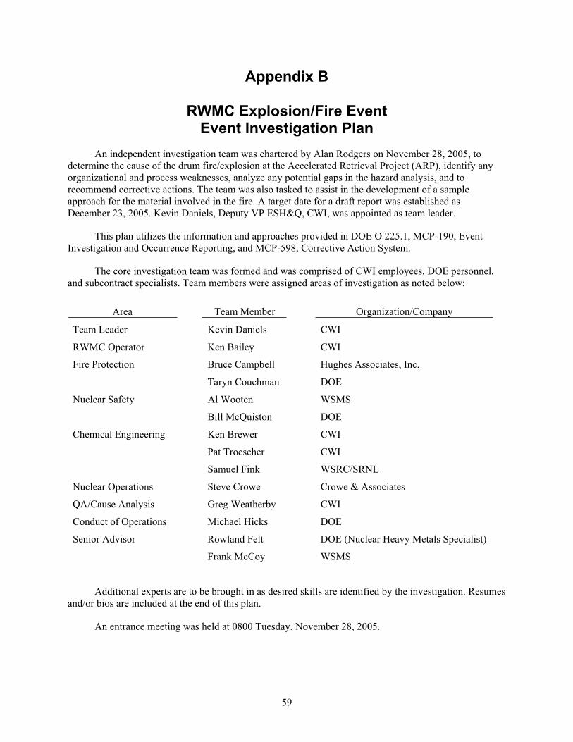
59
Appendix B
RWMC Explosion/Fire Event Event Investigation Plan
An independent investigation team was chartered by Alan Rodgers on November 28, 2005, to
determine the cause of the drum fire/explosion at the Accelerated Retrieval Project (ARP), identify any
organizational and process weaknesses, analyze any potential gaps in the hazard analysis, and to
recommend corrective actions. The team was also tasked to assist in the development of a sample
approach for the material involved in the fire. A target date for a draft report was established as
December 23, 2005. Kevin Daniels, Deputy VP ESH&Q, CWI, was appointed as team leader.
This plan utilizes the information and approaches provided in DOE O 225.1, MCP-190, Event
Investigation and Occurrence Reporting, and MCP-598, Corrective Action System.
The core investigation team was formed and was comprised of CWI employees, DOE personnel,
and subcontract specialists. Team members were assigned areas of investigation as noted below:
Area Team Member Organization/Company
Team Leader Kevin Daniels CWI
RWMC Operator Ken Bailey CWI
Fire Protection Bruce Campbell Hughes Associates, Inc.
Taryn Couchman DOE
Nuclear Safety Al Wooten WSMS
Bill McQuiston DOE
Chemical Engineering Ken Brewer CWI
Pat Troescher CWI
Samuel Fink WSRC/SRNL
Nuclear Operations Steve Crowe Crowe & Associates
QA/Cause Analysis Greg Weatherby CWI
Conduct of Operations Michael Hicks DOE
Senior Advisor Rowland Felt DOE (Nuclear Heavy Metals Specialist)
Frank McCoy WSMS
Additional experts are to be brought in as desired skills are identified by the investigation. Resumes
and/or bios are included at the end of this plan.
An entrance meeting was held at 0800 Tuesday, November 28, 2005.
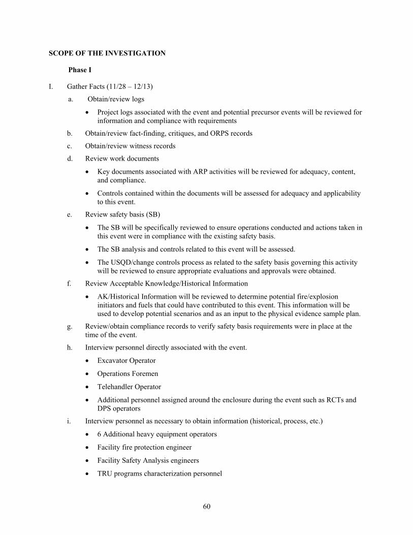
60
SCOPE OF THE INVESTIGATION
Phase I
I. Gather Facts (11/28 – 12/13)
a. Obtain/review logs
Project logs associated with the event and potential precursor events will be reviewed for
information and compliance with requirements
b. Obtain/review fact-finding, critiques, and ORPS records
c. Obtain/review witness records
d. Review work documents
Key documents associated with ARP activities will be reviewed for adequacy, content,
and compliance.
Controls contained within the documents will be assessed for adequacy and applicability
to this event.
e. Review safety basis (SB)
The SB will be specifically reviewed to ensure operations conducted and actions taken in
this event were in compliance with the existing safety basis.
The SB analysis and controls related to this event will be assessed.
The USQD/change controls process as related to the safety basis governing this activity
will be reviewed to ensure appropriate evaluations and approvals were obtained.
f. Review Acceptable Knowledge/Historical Information
AK/Historical Information will be reviewed to determine potential fire/explosion
initiators and fuels that could have contributed to this event. This information will be
used to develop potential scenarios and as an input to the physical evidence sample plan.
g. Review/obtain compliance records to verify safety basis requirements were in place at the
time of the event.
h. Interview personnel directly associated with the event.
Excavator Operator
Operations Foremen
Telehandler Operator
Additional personnel assigned around the enclosure during the event such as RCTs and
DPS operators
i. Interview personnel as necessary to obtain information (historical, process, etc.)
6 Additional heavy equipment operators
Facility fire protection engineer
Facility Safety Analysis engineers
TRU programs characterization personnel
61
Emergency response personnel as necessary to determine response actions
Shift Supervisors
Project VP
ARP Manager
Personnel associated with previous contractor operations
j. Examine the accident scene using the CCTV and on initial re-entry. The accident scene
examination is to be recorded and will focus on identification and location marking of
potential debris from the event. Attempts should be made to identify items that could have
potentially hit the excavator window.
k. Review video(s) of the event to determine if event was captured on the video and determine if
the response was appropriate. Additionally determine if there were any possible precursor
events that were captured on video.
l. Since there is a possibility that the fire could reignite when the material is exposed to air, the
procedure for reentry should include specific instruction to cover the area with dirt if a fire
occurs. Use of the dust suppression system would not be effective on the expected type of
fire.
m. Identify tests/sampling necessary to support investigation based on evaluation of the above
steps. Ensure samples can confirm or disprove potential fire/explosion scenarios developed in
Step f above.
Since the excavator bucket was in the fire, there is a possibility that fire/smoke residue
could remain on the bucket. Take smear samples of the bucket and analyze for heavy
metals, hydrocarbons, uranium and VOCs.
The video showed smoke being pulled towards the ventilation exhausts. Interviews with
the project indicated that the prefilters had been changed on the exhausts within the last
30 days. Prefilters in the area where the smoke was exiting will be removed and media
sampled.
During interviews, it was determined that a spray fixative (DuraSoil) is used in the
Retrieval Area to control dust around the excavation. This liquid is listed as being
combustible. Water is supposed to be used during digging operations for dust suppression
and for fire response. Sample the liquid in the tank on the excavator to determine what is
in the tank.
Excavation of the drum should be done in a controlled manner such that the material
excavated is identified as to where it came from and approximately what depth. This will
allow later reconstruction of where debris was if any is found.
Samples will be obtained of the dirt immediately around the drum when it is unearthed.
These samples will be analyzed for VOCs, heavy metals, uranium, hydrocarbons,
TIC/TOC, weight gain/loss on combustion, XRD, and anion analysis.
A gamma spec analysis will be performed as soon as possible on material from the drum
to determine if uranium is present.
Project is to provide the location of the nearest seismic recorders and the results of the
monitoring for the period of the event.
62
n. Review policies, standards, and requirements applicable to the event to be included in the
evaluation of safety management systems. This review includes an evaluation of the event
response actions taken by the facility.
II. Analyze the Facts and Identify Causal Factors and Judgments of Need (11/28-12/16)
a. Develop Event and Causal Factor Chart (E&CF) per MCP-598, Corrective Action System,
based on data gathered in Step I. The E&CF method is useful in identifying multiple causes
and graphically depicting triggering conditions and events necessary to cause an
accident/event.
b. Identify potential accident scenarios/materials of concern/initiators based on facts gathered in
Phase I. Integrate fire/explosion scenarios with all data gathered regarding fire/explosion
initiators, actions taken during event, and data gathered regarding event.
c. Refine needs for tests/sampling necessary to fully characterize materials involved in the
event, if necessary based on E&CF.
d. Review Operations re-entry and sampling plan to ensure it supports investigation needs to
record evidence, tests appropriately will provide data to prove/disprove potential
causes/scenarios leading to the event and for operational safety during sampling. Ensure
evidence is properly segmented and stored for any future data analysis.
Phase II
III. Obtain Physical Evidence (~ 12/13- 12/23)
a. Review Operations re-entry and sampling plan to ensure it supports investigation needs as
developed in Step II d.
b. Review results of sample data when received.
c. Request additional data analysis as required.
IV. Revise E&CF based on physical results (12/13 – until results received)
a. Confirm accident scenario based on physical sample/NDA results.
b. Identify follow-on sampling needs if required.
c. Evaluate effectiveness of safety management systems once E&CF is finalized. Identify any
areas of concern or weaknesses. Conduct additional reviews and interviews as necessary to
ensure adequate information is obtained to make a team conclusion.
d. Evaluate effectiveness of line management oversight as related to event. Identify areas where
management oversight could have prevented or mitigated this event. Identify weaknesses
and strengths.
V. Develop Draft Investigation Report (12/23)
a. Identify Judgments of Need. Judgments of Need are defined as “managerial controls and
safety measures necessary to prevent or minimize the probability or severity of a recurrence
of an accident.” These shall be based on objective analysis of facts, root and contributing
causes, and management systems that could have prevented the accident.
b. Identify Areas for Improvement and Recommendations.
63
c. Conduct Factual Accuracy Review of Draft by Line Management.
d. Conduct Technical Accuracy Review.
e. Ensure analysis of management control and safety systems included in report as identified in
Steps IV c and d.
f. Conduct classification review.
g. If results from physical evidence gathering/sampling are not available, select team members
will reconvene. The results will be reviewed to confirm the cause of the event. Completion
date of this step will be determined following receipt of results.
VI. Present to CWI/DOE Management
VII. Issue Final Report – Following issuance of the final report, the team leader (and selected team
members) will support the facility in development and issuance of lessons learned.
The investigation team will conduct a weekly conference call to update interested parties. A
schedule and conference number will be distributed by the team leader. Periodicity and time of the
conference call will be re-evaluated as the investigation progresses.

64
65
Appendix C
Review of the Accelerated Retrieval Project Safety Basis During CWI Transition

66
67
Appendix C
Review of the Accelerated Retrieval Project Safety Basis During CWI Transition
At the request of the Idaho Closure Project Transition Team, a review was conducted on the
Accelerated Retrieval Project (ARP). The review focused on compliance with the Authorization Basis.
The review was to identify any noncompliances to requirements or any significant improvements that
should be implemented at the time of contract change over.
The ARP provides a method of retrieving and managing TRU waste buried at the Idaho
Radioactive Waste Management Facility (RWMC). The ARP operation is analyzed in Appendix K of the
RWMC Safety Analysis Report (SAR). Appendix K is a stand alone analysis encompassing all activities
performed as part of the ARP, including waste retrieval, segregation, packaging, sampling, visual
examination, fissile assay and interim storage. The ARP is considered a temporary, environmental
restoration project and much of the control selection is based on the temporary nature of the activity.
Method of Review
Document reviews, facility walkdowns and key personnel interviews.
Documents reviewed:
Radioactive Waste Management Complex Safety Analysis Report, Addendum K. The
Accelerated Retrieval Project, SAR-4 Revision 9, Effective Date: 02/21/05.
Radioactive Waste Management Complex Technical Safety Requirements, TSR-4
Revision 3, Effective Date, 02/21/05.
Health and Safety Plan for the Accelerated Retrieval Project, ICP/EXT-04-00209, Revision
5
Interviews:
Operations personnel
Cognizant Engineer
Safety Bases Engineer
Summary
The review has concluded that the ARP Safety Basis is compliant with 10 CFR 830 and the safe
harbor DOE Standard 3009 Change Notice No. 2. The review has also concluded that the facility appears
to be operating within the bounds of the SAR with appropriate controls in place for protection of the
public and the worker. Some issues were identified and are discussed below.
Issue: A concern exists that future operations may not be adequately bounded (i.e., the assumed
source term may not be reasonably bounding for all cases. There is also a concern that system
engineers do not have a formal program for periodic verification of Authorization Bases
assumptions.
68
For each of the Design Basis Accidents a value of 3.6 Ci/drum is used as reasonably bounding
(95% Upper Confidence Level) activity content. The original basis document for the SDA is EDF-3543
that evaluated per drum inventories from a host of different records. In EDF-3543 the bounding (99th
percentile) drum is evaluated as containing 31.8 Pu-239 equivalent curies and the average drum as
containing 3.6 Pu-239 equivalent curies. The 3.6 Ci value was justified by the much lower than expected
values seen for the Pit 9 GEM Project remediation.
Drum data for drums assayed to date from row “A” appears to confirm that 3.6 Ci is reasonably
bounding for waste processed to date. Of 271 drums from the Drum Packaging Station (DPS), only four
had exceeded 200 Fissile Gram Equivalents (FGE). System engineers indicated that about a 5:1
“concentration” of waste was occurring by separating and drumming the targeted waste. 200 FGE at DPS
would then equate to about 40 FGE per drum in row “A.” Dividing this by a rough rule of thumb of
15 FGE/1 Ci of aged weapons grade plutonium, which gives a value of 2.7 Ci/drum. Therefore of the 271
drums processed through initial assay (as of April 21), four have exceeded 2.7 Ci, roughly validating the
current SAR assumptions.
However, additional data provided on the volumetric distribution of targeted waste indicates that
Row “A” is relatively low in targeted waste concentration (approximately 0.6% of the ARP1 targeted
waste is contained in each grid of Row “A”). Several of the grids D5, E6, E7, H4, H5, and I5 contain
more than 4% of the total ARP1 targeted waste by volume. Specific curie data for each grid was not
available at this time, but it can be surmised that higher volumetric concentration of targeted waste in
these could result in source terms as much as an order of magnitude higher than that analyzed in the SAR.
Current operations are bounded by the SAR, but future operations are still in question.
As an additional note, the AB Engineer and the System Engineer do not appear to have any formal
(or informal) program to validate that assumptions used in the Safety Analysis are valid on a forward fit
basis. A formal program would be advised on a project such as ARP where many of the assumptions rely
on data of such a varied pedigree.
Issue: The stacking of large quantities of trench material outside the trench is not addressed
explicitly (or implicitly) in the SAR.
Authorization bases personnel did not appear to be aware of the activity to dig up a large portion of
the trench (almost half of Row “A,” estimated to be about 400 drums) and place the material in one large
pile in the RE without segregation of targeted waste at this time. The SAR does not explicitly describe
how much dirt and waste might be uncovered or exposed at any one time. However, the system engineer
stated that the original excavation plan did not describe this activity. By examination it does not appear
that this would have an impact on the bounding accident analyses; however, the facility has committed to
complete an Unreviewed Safety Question to assure that this activity is covered.
Issue: The ventilation system for ARP is identified as Defense in Depth (DiD) which may be
contrary to DNFSB Recommendation 2004-2.
The SAR appropriately classifies the ARP ventilation system as DiD and not Safety Class or Safety
Significant. From the SAR: “The RE exhaust ventilation system shall be in operation during waste
handling activities in the RE. This system has been selected as a TSR control because it was identified in
the hazard evaluation as providing defense in-depth for multiple hazards. It also is an important system
for contamination control during routine operations.” (Addendum K, Section 3.3.2.3.2.2, Technical Safety
Requirements). This classification is supported by the described accident progressions in the SAR.
69
However, the Board, in Recommendation 2004-2 has taken a position that almost all ventilation
systems associated with Hazard Category 2 or 3 facilities should be Safety Class or Safety Significant (a
few specific exceptions are called our in the recommendation). This could present a challenge to the new
management team should the Board challenge the current classification.
Issue: The current SAR will require significant changes to authorize the improved methodologies
proposed under this contract.
Examples of areas that will need to be addressed include: The current SAR recognizes the
excavator driver and the telehandler driver as the only personnel allowed within the RE during operations.
Placing operators within the enclosure for hands on activities will need to be addressed. Also, the SAR
identifies hazards such as picric acid (a potential impact sensitive chemical) that will need to be addressed
to ensure controls are in place to protect the worker.

70
71
Appendix D
Extinguishment of Postulated Fires in the Pit 4 Enclosure at the Radioactive Waste Management Complex,
Idaho National Laboratory

72
73
Extinguishment of Postulated Fires in the Pit 4 Enclosure at
the Radioactive Waste Management Complex (RWMC),
Idaho National Laboratory
Prepared by
Bruce Campbell
Hughes Associates, Inc.
2 Garden Center, Suite 204
Broomfield, Colorado 80020
303-439-0485
303-439-7160 (fax)
Jerry Stakebake
1487 Lodge Ct.
Boulder, Colorado 80303
(303) 449-0876
February 28, 2006
74
Table of Contents
D-1. EXECUTIVE SUMMARY .............................................................................................................. 75
D-2. BACKGROUND.............................................................................................................................. 76
D-3. EXTINGUISHMENT OF PYROPHORIC URANIUM FIRES ...................................................... 78
D-4. EXTINGUISHING OTHER CLASS D, NON-URANIUM FIRES ................................................ 79
D-5. EXTINGUISHING GRAPHITE FIRES .......................................................................................... 79
D-6. EXTINGUISHING AGENTS EVALUATED BUT NOT RECOMMENDED.............................. 80
D-7. FIRE PROPAGATION .................................................................................................................... 80
D-8. RECOMMENDATIONS ................................................................................................................. 81
D-8.1 Pyrophoric Fires .................................................................................................................. 81
D-8.2 Class A Fires ....................................................................................................................... 82
D-9. CONCLUSIONS .............................................................................................................................. 83
D-10. REFERENCES................................................................................................................................. 83
75
Extinguishment of Postulated Fires in the Pit 4 Enclosure at the Radioactive Waste Management
Complex (RWMC) at the Idaho National Laboratory
D-1. EXECUTIVE SUMMARY
The purpose of this report is to provide technically based recommendations on the preferred
methods to properly and efficiently extinguish the four types of possible fires that were identified in the
preliminary investigation of the event that occurred in November 2005.
The event of November 21, 2005 occurred during routine operations while retrieving buried steel
waste drums. After retrieving a drum, an initiator caused the drum to ignite. According to interviews with
the operator, the initial stages of the fire included some type of pressurized event that caused a foreign
object to strike the windshield of the excavator. The excavator operator immediately applied water from
the water based dust suppression system. The water was not effective in controlling the fire. The operator
then applied nearby soil using the excavator and completely covered the drum and a second near-by drum
that initially appeared to be either involved or engulfed by the initial drum. Once a thick layer of dirt had
been shoveled onto the combusting drum, the flames were diminished. The operator testified that he
applied 2 to 3 or more feet of dirt; during re-entry evolutions, the depth of bury was confirmed to be
approximately 2 to 3 feet. Reentry confirmed that the fire did not propagate to the second drum, even
though it appeared to be partially or wholly engulfed by the fire in the first drum. The actions of the
operator were to an approved procedure, effective and commendable.
Via a thermal imaging camera, it was noted that the drum continued to burn (or oxidize) for several
days post fire. The temperatures at the surface (approximately 3 feet above the drum) indicated an
increase of 15 degrees F. This fact is important for discussions within this report as to which is the most
appropriate fire-extinguishing agent for any future fires in the Accelerated Retrieval Project (ARP).
At the time of the fire, there were two approved and documented methods of extinguishing fires at
the ARP, the first being the water-based dust suppression system, and the second being the application of
dirt by the operator(s).
The initial investigation identified four higher probability initiators: combustion/rapid oxidation of
pyrophoric uranium, combustion/rapid oxidation of pyrophoric metals, ignition of graphite, or
combustion of hydrogen that would have been the source of the ignition of other materials. Re-entry
evidence (i.e., the presence of a 30-gallon inner drum and analytical results) indicate that the content of
the involved drum was roaster uranium oxide.
Extinguishment of these types of fires was evaluated from a routine nonnuclear industrial
standpoint and from a nuclear industrial standpoint. Metal fires in a nonnuclear industrial atmosphere are
generally extinguished via commercially available Class D extinguishing agents. The most common agent
is Met-L-X dry powder. Met-L-X can be applied using a UL listed fire extinguishers or by applying it
from five gallon (or larger) buckets. Met-L-X is effective in controlling or extinguishing smaller amounts
of most combustible metals. In a nuclear industrial facility, Met-L-X is typically utilized for most
nonradioactive combustible metals. For nuclear material, magnesium oxide is typically used based on past
experiments(3) and actual fire experience.
Water can be extremely volatile in extinguishing certain types of Class D fires. Magnesium in
particular has a violent reaction when exposed to water, due to the breakdown of water into hydrogen.
Water does not typically react violently with uranium or plutonium at lower temperatures, but it is also
not effective in extinguishing this type of fire. Additionally water can react with the plutonium or uranium
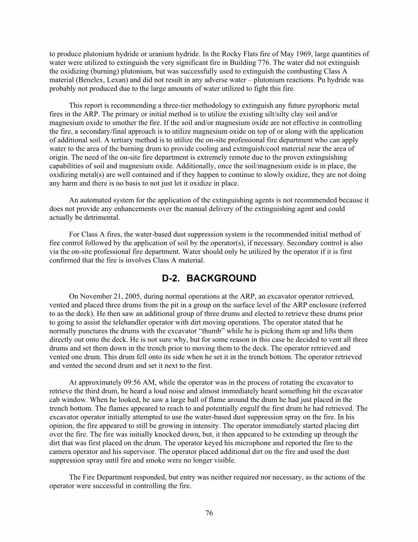
76
to produce plutonium hydride or uranium hydride. In the Rocky Flats fire of May 1969, large quantities of
water were utilized to extinguish the very significant fire in Building 776. The water did not extinguish
the oxidizing (burning) plutonium, but was successfully used to extinguish the combusting Class A
material (Benelex, Lexan) and did not result in any adverse water – plutonium reactions. Pu hydride was
probably not produced due to the large amounts of water utilized to fight this fire.
This report is recommending a three-tier methodology to extinguish any future pyrophoric metal
fires in the ARP. The primary or initial method is to utilize the existing silt/silty clay soil and/or
magnesium oxide to smother the fire. If the soil and/or magnesium oxide are not effective in controlling
the fire, a secondary/final approach is to utilize magnesium oxide on top of or along with the application
of additional soil. A tertiary method is to utilize the on-site professional fire department who can apply
water to the area of the burning drum to provide cooling and extinguish/cool material near the area of
origin. The need of the on-site fire department is extremely remote due to the proven extinguishing
capabilities of soil and magnesium oxide. Additionally, once the soil/magnesium oxide is in place, the
oxidizing metal(s) are well contained and if they happen to continue to slowly oxidize, they are not doing
any harm and there is no basis to not just let it oxidize in place.
An automated system for the application of the extinguishing agents is not recommended because it
does not provide any enhancements over the manual delivery of the extinguishing agent and could
actually be detrimental.
For Class A fires, the water-based dust suppression system is the recommended initial method of
fire control followed by the application of soil by the operator(s), if necessary. Secondary control is also
via the on-site professional fire department. Water should only be utilized by the operator if it is first
confirmed that the fire is involves Class A material.
D-2. BACKGROUND
On November 21, 2005, during normal operations at the ARP, an excavator operator retrieved,
vented and placed three drums from the pit in a group on the surface level of the ARP enclosure (referred
to as the deck). He then saw an additional group of three drums and elected to retrieve these drums prior
to going to assist the telehandler operator with dirt moving operations. The operator stated that he
normally punctures the drums with the excavator “thumb” while he is picking them up and lifts them
directly out onto the deck. He is not sure why, but for some reason in this case he decided to vent all three
drums and set them down in the trench prior to moving them to the deck. The operator retrieved and
vented one drum. This drum fell onto its side when he set it in the trench bottom. The operator retrieved
and vented the second drum and set it next to the first.
At approximately 09:56 AM, while the operator was in the process of rotating the excavator to
retrieve the third drum, he heard a loud noise and almost immediately heard something hit the excavator
cab window. When he looked, he saw a large ball of flame around the drum he had just placed in the
trench bottom. The flames appeared to reach to and potentially engulf the first drum he had retrieved. The
excavator operator initially attempted to use the water-based dust suppression spray on the fire. In his
opinion, the fire appeared to still be growing in intensity. The operator immediately started placing dirt
over the fire. The fire was initially knocked down, but, it then appeared to be extending up through the
dirt that was first placed on the drum. The operator keyed his microphone and reported the fire to the
camera operator and his supervisor. The operator placed additional dirt on the fire and used the dust
suppression spray until fire and smoke were no longer visible.
The Fire Department responded, but entry was neither required nor necessary, as the actions of the
operator were successful in controlling the fire.
77
The Pit 4 area is not provided with a fixed water distribution system. The closest fire hydrant is
located 1,500 ft from the ARP project site, at the west edge of the RWMC operations area. Water for any
extended suppression efforts will be supplied by the fire department through an extended large diameter
hose lay. To provide the minimum required water supply, a trailer is provided with 3,000 ft of pre-
connected 4-in.-diameter hose used to reach the Retrieval Enclosure. An additional 400 ft of 4-in. hose is
available from the fire department engine. The fire department pumper is provided with 500 gallons of
water; further, there are 2,000 gallons of water available from a fire department tender that accompanies
the pumper and there is a 4,000-gallon water tank at the ARP that has a connection for fire department
use.
To supplement the available water supply, a 4,000-gal firewater storage tank is installed near the
Retrieval Enclosure. The water tank is equipped with an isolation valve and a 4-in. standardized
connection to allow prompt connection to the fire department water tender or engine pump inlet.
The Vice President in charge of RWMC operations issued a letter chartering an independent
investigation team to perform the following tasks:
Determine the cause of the drum fire/explosion,
Identify organizational and process weaknesses,
Analyze potential gaps in hazards analysis,
Develop recommendations regarding the path forward to sampling and investigation of the fire site,
Recommend corrective actions, and
Provide a draft report by December 23, 2005
The team in their preliminary report determined that the most likely reactions (initiators) that
occurred to cause and sustain the fire were:
Combustion/rapid oxidation of pyrophoric uranium (e.g., uranium hydride or poorly oxidized
roaster uranium oxide),
Combustion/rapid oxidation of pyrophoric metals (e.g., zirconium, magnesium, or calcium),
Ignition of graphite (which is difficult to ignite but could have been ignited by another source) and
could have resulted in persistent oxidation, or
Combustion of hydrogen (that could have been ignited by drum venting and been the heat source
for other reactions and combustion).
Based on recent re-entry results, it appears that roaster oxide was contained in a 30-gallon drum
within a 55-gallon drum, and that the fire involved the combustion/rapid oxidation of pyrophoric
uranium. Initial ignition could have been via a uranium hydride reaction. Uranium hydride is very
reactive and does not take much energy to initiate a reaction, thus the simple act of piercing and removing
the drum would have been more than enough energy to start the reaction.
78
D-3. EXTINGUISHMENT OF PYROPHORIC URANIUM FIRES
There have been several cases throughout the DOE Complex where massive pieces of metallic
uranium have ignited at room temperature. Spontaneous fires involving uranium chips, however, are
much more common.(1,2) In one case, ignition occurred after 6 months of storage; and in a second case,
briquetted uranium chips stored in a drum for several weeks ignited when the drum was opened.
Two principles are paramount when attempting to extinguish uranium fires. First is to separate the
reactants (i.e., remove the source of oxygen). The second is to lower the temperature of the
burning/oxidizing uranium, below its ignition temperature of approximately 500 degrees C. Investigations
into methods of extinguishing metal fires have identified possible methods involving small fires;
however, applying these methods to large drum scale quantities of metals is much more difficult. In fact,
the best approach in many cases it to contain the burning metal and allow it to burn/oxidize to completion.
At the Rocky Flats Plant, the standard operating practice by the fire department was to isolate the
combusting material from other combustibles, cover it with magnesium oxide and allow the material to
completely oxidize.
Early research(3)(4) on plutonium metal fires focused on possible materials/mechanisms to either
prevent access to oxygen or to cool the plutonium to below the burning point where metal oxidation is the
only reaction. Approximately 60 tests that utilized 30 kg of plutonium were undertaken. Tests to lower the
temperature of the metal fire involved metal chips and powders that had a high thermal conductivity.
Metals such as copper, iron, and lead were at least partially successful in reducing the fire temperature but
were not successful in actually extinguishing the fire.
Several nonmetal powders and salts were also considered as a possible means of excluding oxygen.
Graphite powder, magnesium oxide sand, and several halide salts were used to attempt to smother the
metal fire and met with mixed success.
Met-L-X is a dry powder (not to be confused with dry chemical) composed of a salt base plus a
polymer for sealing and other additives to render it free-flowing and not cause heat caking or cracking. It
is Underwriters Laboratories (UL) listed as an extinguishing agent for sodium, potassium, sodium-
potassium and magnesium alloys. Met-L-X has also been used but, in one case noted at ANL-W, did not
completely extinguish a uranium hydride fire. The main problem associated with powders is the cracks
formed in the powder by the expanding metal oxide, which permitted additional oxygen to access the
reacting metal. Gaseous agents including argon and halon have been tested and have been proven to be
less effective, particularly for fires outside a glovebox type enclosure.
Magnesium oxide sand and copper powder was found to be the most effective solid extinguishing
agent for rapid heat removal to below the 500 degrees C ignition temperature. These materials were tested
in terms of glovebox-sized fires involving pyrophoric nuclear metals(3). To this day, magnesium oxide is
the preferred extinguishing agent utilized in the DOE complex for pyrophoric nuclear material fires.
Magnesium oxide was used for years at the Rocky Flats Plant and was utilized for a number of small
pyrophoric metal fires within glovebox containment. Typically, small metal containers (about 1 quart in
size) were used to store the magnesium oxide. The magnesium was used either by the operator or by the
on-site fire department. These fires were also controlled due to their placement on the glovebox floor,
which acted as a good heat conduction surface.
A word of caution is appropriate in discussing metal fires. In the case of uranium, pyrophoricity is
exacerbated by the particle size of the metal and also the presence of a pyrophoric hydride on the surface
of the metal. Storage of uranium in an ambient environment is likely to result in the formation of uranium
hydride by the reaction of uranium with water vapor in the atmospheric. In a burning uranium chip
79
incident at Rocky Flats in 1976, chips being transferred in a plastic bag ignited. The operator placed the
burning bag of chips in a 10-gallon can and covered them with water and the fire was extinguished.(5)
However, in another incident involving the production of uranium powder, the powder was collected and
stored under approximately 25 feet of water. At about 1-month intervals, and without prior warning a
geyser about 30 feet high would suddenly develop over the powder and then immediately subside.(6)
It has been noted(7) that large quantities of water have been seen as acceptable as an extinguishing
agent for uranium fires. However, if small amounts of water (such as a spray of water from a portable
extinguisher or fire hose) are used the intensity of the fire can be greatly intensified with the potential for
the release and burning of hydrogen and the generation of uranium hydride. The point is that ignition of
uranium chips stored as a waste material is unpredictable and there are a number of ways ignition can be
triggered. The fact that in one case water was satisfactory as an extinguishing agent did not hold true for
another case where water storage of uranium powder resulted in an explosive-type reaction. The
utilization of water to extinguish uranium/uranium hydride fires is not recommended because of the
potential chemical reaction with the uranium metal.(6,8,9)
In the current incident being investigated, the burning drum was vented at the buried location,
moved farther down the grade to the base of the pit when the flames were detected from the drum after a
few seconds while the drum was being located in the pit. Soil was then placed on top of the drum at this
location. This action served to contain the fire within the trench. It also likely reduced the free access of
oxygen to the burning drum. However, based on the thermal imaging of the area, post fire, it is unlikely
that it actually fully extinguished the fire. Because of the size of the drum and the burial area involved,
covering with soil was the best option for containing the fire.
D-4. EXTINGUISHING OTHER CLASS D, NON-URANIUM FIRES
Extinguishing other Class D fires is somewhat dependent on the type of metal. Met-L-X is
effective and UL listed for sodium, potassium, sodium-potassium and magnesium alloys. Another similar
Class D extinguishing agent; LITH-X is a compound of a special graphite base with additives to render it
free-flowing. It does not cake or crust but excludes air and conducts heat. It is used for lithium fires, and
will also extinguish magnesium, sodium and potassium fires. Further, it can be effective on zirconium,
titanium and sodium-potassium alloy.
Based on the Acceptable Knowledge of the waste buried at Pit 4 and in order to keep the number of
extinguishing agents to an absolute minimum, the use of soil and/or magnesium oxide is the best
approach. It may not be as effective as Met-L-X or LITH –X as an extinguishing agent for certain metal
fires, but it is still effective in forming a tight barrier from oxygen to the oxidizing metal(s).
Also, it is not reasonable or justified to provide multiple sources of extinguishing agents within the
enclosure. Plus, it is nearly impossible for an operator to discern between a roaster oxide fire from other
Class D material fires, and then try to determine the appropriate agent to attack the fire.
D-5. EXTINGUISHING GRAPHITE FIRES
Graphite fires are uncommon due to the high ignition temperature and boiling point of this
material. It was included in the preliminary investigation report as a possible contributor to the persistent
fire under the soil, but deemed unlikely as the initiating fuel source.
The application of soil and/or magnesium oxide is the most appropriate technically justified
approach. In the event the soil and/or magnesium oxide is not successful, the on-site professional fire
80
department can provide large quantities of water to affect final extinguishment, as there are no adverse
water-graphite reactions, other than the generation of steam.
D-6. EXTINGUISHING AGENTS EVALUATED BUT NOT RECOMMENDED
Within this report, several agents were discussed and were not recommended for deployment
within the ARP. Below is a summary of those agents and a recap on the basis for not recommending their
utilization. Important for the consideration for inclusion as a viable extinguishing agent is the
effectiveness of the agent across a broad array of extinguishing targets (nuclear to nonnuclear pyrophoric
metals).
Agent Basis for not Recommending
Met-L-X Not proven effective for uranium fires, not effective for all Class D fires
LITH-X Not proven effective for uranium fires, not effective for all Class D fires
Copper, iron, & lead Not proven effective based on early experimentation.
Gaseous agents; Inert
(argon) and noninert (Halon
1301/Halon 1211)
Inert agents not proven effective in nonglovebox applications, because the
gas cannot be easily contained. Non-inert agents were also not proven to be
ineffective, plus halogenated agents have the potential of reacting
explosively with the burning metal (Halon extinguishers were prohibited
from nuclear facilities at the Rocky Flats due to an explosion involving
carbon tetrachloride and burning plutonium that resulted in a serious
injury).
Water Not effective for Class D fires, in some cases dangerous for certain Class D
metals (e.g. magnesium), effective and recommended for Class A fires.
Water can react with plutonium and uranium to produce plutonium hydride
or uranium hydride, which is highly reactive.
Refer to Section D-8.1 of this appendix report for the rational on not providing an automated
system to deliver the recommended extinguishing agent to control or extinguish a Class D fire.
D-7. FIRE PROPAGATION
The potential for a drum fire propagating to other drums and then escalating into a “dump” type of
deep seated fire was evaluated, to ensure the recommended agents were appropriate to address this type
consequence.
A single drum fire spreading from exposed drum to exposed drum and then progressing to partially
exposed/partially buried drums that could result in a deep seated “dump” fire is highly unlikely based on
the following:
Drum to drum fire propagation did not occur during the fire of November 2005. In this fire, a
near-by drum was either partially or wholly engulfed from the fire from the burning drum and the
contents did not ignite, in no small part due to the quick actions of the operator. This was validated
during reentry.
81
Only a few drums are excavated at any one time and the energy it takes to ignite another drum is
high, thus getting one drum to ignite another is remote. There are a large number of drums stored
on the “deck,” but once the vented drums are removed and situated for moderate term storage
(greater than 24 hours), the chances of ignition is remote.
Drums that are not excavated remain buried and it would seem to be nearly impossible to ignite a
buried drum that only has a small amount of the surface area exposed to the burning drum. The soil
in this case will act just as it does when utilized to extinguish a fire (by providing a thermal heat
sink and keeping oxygen from the contents of the drum).
Testing conducted for the Westinghouse Hanford Company in September of 1996 by Hughes
Associates, Inc.(11) demonstrated that when drums are involved in a pool fire, they only lose their
lid if directly involved with the pool fire. Drums outside but near the pool fire will not lose their
lids nor will there be drum to drumfire propagation.
This type of event is not considered credible at this point. The recommended agents in Section D-8
are as effective in combating this type of propagation scenario as they are in controlling or extinguishing
a drum fire.
D-8. RECOMMENDATIONS
Recommendations are being provided for pyrophoric metal fires and Class A fires respectively.
D-8.1 Pyrophoric Fires
It is recommended that three levels/tiers of fire protection be provided for the ARP for fires
involving roaster oxide, other pyrophoric metals and graphite.
Primary/Initial Approach: The initial extinguishing agent recommended is the existing silt/silty
clay soil and/or magnesium oxide. This approach recognizes the ease of application by the operator(s),
and it should be fine enough to adequately keep oxygen from the burning uranium and also provide
reasonable cooling of the burning uranium.
Should a metal (including uranium) fire initiate in the Drum Packaging Area, the use of magnesium
oxide powder from metal containers would be the most effective method of extinguishing the fire without
any additional untoward reactions.
Secondary/Final Approach: After a moderate amount of soil has been applied to the burning drum,
magnesium oxide can be applied on top of or along with the soil to provide improved smothering
capability.
Tertiary Approach: In the unlikely event the soil and/or magnesium oxide extinguishing agents are
not successful in controlling the fire, the on-site professional fire department has the option of utilizing
large quantities of water to cool down the area and near-by drums if they are not being controlled by the
soil/magnesium oxide combination. The use of water should be an extreme last resort and should only be
applied in large quantities to reduce the changes of the formation of uranium hydride, which is very
volatile/reactive. Formation of the uranium hydride can occur well after the application of the water,
which could result in a reactive compounds being present in the pit well after the fire event. This could
result in future fire events even after the initial fire has been extinguished.
82
Application/deployment of the soil and/or magnesium oxide should be manually by the operators
within the enclosure. By manually delivering the agent to the seat of the fire, control and possible
extinguishment occurs much faster. The delivery location of the agent can be adjusted during the
extinguishing activity to ensure optimum placement of the extinguishing agent. The application should be
as simple as possible to increase the reliability of the approach. It can be as simple as storing the soil in
pile(s), that are pre-staged by the operators and readily available. The magnesium oxide could be stored in
piles on the ground, also in pre-staged locations, or also stored in metal dumpsters. The final deployment
method should be developed by the engineering department with input and final approval from the facility
fire protection engineer. Engineering should take into consideration the limitations of the existing
equipment, load capacity and the exhumation operations in their design.
There is no technical basis to invest in an automated suppression system as it will not improve the
application of the extinguishing agents, and it could also be much less effective. An automated system has
the following disadvantages:
Cost of design: significant costs would be associated with designing a reliable system.
An automatic system tends to flood a pre-defined area with agent, versus delivering an optimum
quantity of agent to a well defined smaller area.
Lack of Availability: there are no known automated systems that would discharge magnesium
oxide. Existing systems that deploy Met-L-X could be converted to magnesium oxide, but would
not be UL listed, and the costs to get a system such as this listed would be high and very time
consuming. As discussed earlier, Met-L-X is not a recommended agent for pyrophoric uranium.
The required inspection, testing and maintenance of this type of system would be costly and subject
personnel to unnecessary and unwarranted radiation exposures.
The system would have questionable reliability and could be sensitive to a hostile environment
(temperatures, particulates), as found in the ARP.
A system with adequate mobility would be difficult to engineer. The system would need to be
sufficiently mobile to ensure quick and effective application of the extinguishing agent.
Ansul Incorporated of Marinette, WI, who is a major manufacturer of Met-L-X dry powder,
extinguishers and systems states in their white paper(10) on dry power agents that “Generally a fixed
nozzle system will be the most expensive and least effective method for protection of these hazards.
Except in special situations, they are limited to the application of a blanket agent on horizontal surfaces.
Typically these systems will require more agent to protect the same hazard. In many cases, this may be an
order of magnitude higher than required by portables.”
D-8.2 Class A Fires
For fires involving Class A materials, the following approach is recommended.
Primary/Initial Attack: Utilize the on-board water-based dust suppression system. Utilization of the
water-based dust suppression system should only be after it is confirmed by the operator that the burning
material is Class A. If there is any doubt, the operator should utilize the existing silt/silty clay soil to
extinguish the fire.
83
Secondary/Final Attack: Utilize the existing silt/silty clay soil to smother the burning Class A
material.
D-9. CONCLUSIONS
This report provided an analysis of the facts as of the date it was prepared of the fire event of
November 2005. The following conclusions were reached:
The actions of the operator were appropriate, effective and commendable.
For pyrophoric fires the existing soil and/or magnesium oxide were concluded to be the most
technically appropriate extinguishing agent.
A three-tiered approach to extinguishment of pyrophoric metal fires is technically defendable. The
approach is based on the effectiveness of the selected agents as well as the ease and speed of
application.
- Soil and/or magnesium oxide manually deployed by the operator(s)
- Water from the on-site professional fire department, only as a last resort and in large
quantities.
An automated fire suppression delivery system is neither recommended nor warranted and could
result in less effective fire fighting efforts.
Water from the dust suppression system followed by the application of dirt if necessary is the best
suppression method for obvious Class A fires (trash, misc. class A combustibles), providing the
operator has verified that the fire is a Class A fire.
D-10. REFERENCES
1. Jerry L. Stakebake and David W. Osborn, 1994, “The Ignitability Potential of Uranium Roaster
Oxide,” Report TDR-94-015, Rocky Flats Environmental Technology Site, May 26, 1994.
2. M. Silva, 1992, “An Assessment of the Flammability and Explosion Potential of Defense
Transuranic Waste,” Nuclear Safety, 33 (1992) p.220. [1970 waste drum fire at INEEL], [1982
ignition of concrete billets containing uranium at Hanford], [1985 uranium scrap fire at Y-12].
3. R. E. Felt, 1967, “Burning and Extinguishing Characteristics of Plutonium Metal Fires,” Hanford
Isochem Inc. Report ISO-756, August 1967.
4. DOE/ANL, “Plutonium Fire Experiments,” Presented at the DOE/ANL Training Course on
Prevention of Significant Safety-Related Events in the Operation of DOE Nuclear Facilities.
5. RFP, 1976, “Report of Investigating Committee on D-38 Chip Fire in Building 448,” Internal
Rocky Flats R
6. Richard B. Smith, 1956, “Pyrophoricity – A Technical Mystery Under Vigorous Attack,”
Nucleonics, 14 (1956) p. 28.
84
7. DOE, 1994, “DOE Handbook Primer on Spontaneous Heating and Pyrophoricity,” U.S.
Department of Energy Report PB94-974330, December 1994.
8. Hanford, 1954, “AEC Uranium Fire Experience,” Hanford Report HAN-64841, September 1954.
9. M. Epstein, W. Luangdllok, M. G. Plys, and H. K. Fauska, 1996, “On Prediction of the Ignition
Potential of Uranium Metal and Hydride,” Nuclear Safety, 37 (1996), p. 12.
10. Ansul, 1998, “Fighting Fires with Dry Powder Agents,” White Paper 1013, Ansul Incorporated,
Marinette, WI, 54143, 715-735-7411, 1998.
11. C. Beyler, 1996, “Evaluation of Solid Waste Drum Performance Methodology,” Hughes
Associates, Inc., Hanford Report WHC-SD-WM-TRP-246, Rev. 0, September 9, 1996.