Embed Size (px)
Citation preview

Independent Engineer’s Report for the Gainesville Renewable Energy Center
Gainesville Regional Utilities
GREC Independent Engineer’s Report Project No. 101300
8/11/2017

9400 Ward Parkway \ Kansas City, MO 64114
O 816-333-9400 \ F 816-333-3690 \ burnsmcd.com
August 11, 2017 Mr. Tom Brown Chief Operating Officer Gainesville Regional Utilities 301 SE 4th Avenue Gainesville, Florida 32601 Re: Gainesville Renewable Energy Center Independent Engineer’s Report Dear Mr. Brown: Burns & McDonnell Engineering Company, Inc. (“Burns & McDonnell”) was retained by Gainesville Regional Utilities (“GRU”) to prepare an Independent Engineer’s Report (“IE Report”) on the Gainesville Renewable Energy Center (“Plant”). The Plant is a biomass-fired power production facility with a nameplate capacity of approximately 100 MW located in Gainesville, Florida. GRU is considering purchasing the Plant. The purpose of this IE Report was to evaluate whether the Plant was designed, permitted, and constructed in a manner that can provide a long-term, dependable power generating resource. Based on the information reviewed and the results of the IE Report summarized herein, Burns & McDonnell concludes that the Plant appears to be designed and generally constructed by industry standards for biomass-fueled power plant. Overall, Burns & McDonnell believes the Plant will be fully capable of providing long-term, reliable service as an intermediate generation resource if the Plant is operated and continually maintained in accordance with good utility practice. If you have any questions regarding this IE report, please contact me at 816-822-3459 or [email protected]. Sincerely,
Mike Borgstadt, PE Project Manager MEB/meb Enclosure

Independent Engineer’s Report for the Gainesville Renewable Energy
Center
prepared for
Gainesville Regional Utilities GREC Independent Engineer’s Report
Gainesville, Florida
Project No. 101300
8/11/2017
prepared by
Burns & McDonnell Engineering Company, Inc. Kansas City, Missouri
COPYRIGHT © 2017 BURNS & McDONNELL ENGINEERING COMPANY, INC.

GREC Independent Engineer’s Report Table of Contents
Gainesville Regional Utilities TOC-1 Burns & McDonnell
TABLE OF CONTENTS
Page No.
1.0 EXECUTIVE SUMMARY ................................................................................... 1-1 1.1 Introduction .......................................................................................................... 1-1 1.2 Conclusions .......................................................................................................... 1-1
2.0 SITE VISIT......................................................................................................... 2-1
3.0 PLANT DESCRIPTION ..................................................................................... 3-1 3.1 General Introduction ............................................................................................ 3-2
3.1.1 Site Conditions ...................................................................................... 3-4 3.1.2 Civil & Structural Design ..................................................................... 3-4
3.2 Power Block ......................................................................................................... 3-6 3.2.1 BFB Boiler Technology Description .................................................... 3-6 3.2.2 Steam Cycle Description..................................................................... 3-10 3.2.3 Steam Turbine and Generator ............................................................. 3-11 3.2.4 Emissions Control ............................................................................... 3-12
3.3 Material Handling .............................................................................................. 3-12 3.3.1 Fuel Conveying ................................................................................... 3-12 3.3.2 Ash Collection and Storage ................................................................ 3-16
3.4 Water Supply and Treatment ............................................................................. 3-16 3.5 Wastewater Treatment Systems ......................................................................... 3-17
3.5.1 Process Wastewater ............................................................................ 3-17 3.5.2 Potentially Oily Wastewater ............................................................... 3-17 3.5.3 Sanitary Wastewater ........................................................................... 3-17
3.6 Plant Electrical Systems ..................................................................................... 3-17 3.6.1 Auxiliary Electric System ................................................................... 3-18 3.6.2 Generator Step-Up Transformer ......................................................... 3-18 3.6.3 Station Service (SS) Transformer ....................................................... 3-18 3.6.4 Direct Current and Critical Alternating Current Systems ................... 3-18 3.6.5 Grounding, Lighting, and Cathodic Protection Systems .................... 3-19
3.7 Transmission & Electrical Interconnection ....................................................... 3-19 3.8 Balance of Plant and Operation Systems ........................................................... 3-19
3.8.1 Fire Protection Considerations ............................................................ 3-19 3.8.2 Balance-of-Plant Mechanical Systems ............................................... 3-20
3.9 Instrumentation and Control System ................................................................. 3-20
4.0 OPERATIONS & MAINTENANCE PRACTICES .............................................. 4-1 4.1 Operating Philosophy........................................................................................... 4-1 4.2 Plant Operations & Performance ......................................................................... 4-1
4.2.1 Plant Staffing ........................................................................................ 4-1 4.2.2 Plant Operating Statistics ...................................................................... 4-3 4.2.3 Thermal Performance............................................................................ 4-4

GREC Independent Engineer’s Report Table of Contents
Gainesville Regional Utilities TOC-2 Burns & McDonnell
4.3 Fuel Supply .......................................................................................................... 4-7 4.4 Non-Fuel O&M Expenses.................................................................................. 4-10 4.5 Major Maintenance ............................................................................................ 4-11 4.6 Spare Parts Inventory ......................................................................................... 4-13
5.0 KEY CONTRACTS AND AGREEMENTS ......................................................... 5-1 5.1 Biomass Services and Fuel Management Agreement .......................................... 5-1 5.2 Fuel Supply Agreements ...................................................................................... 5-2 5.3 Reclaimed Water Supply Memorandum of Understanding ................................. 5-4 5.4 Operations & Maintenance Agreement ............................................................... 5-6 5.5 Power Purchase Agreement ................................................................................. 5-7 5.6 Interconnection Agreement .................................................................................. 5-7 5.7 Lease Agreement ................................................................................................. 5-7 5.8 Natural Gas Supply .............................................................................................. 5-7
6.0 ENVIRONMENTAL REVIEW ............................................................................ 6-1 6.1 Air Quality ........................................................................................................... 6-1
6.1.1 Prevention of Significant Deterioration ................................................ 6-2 6.1.2 Limits and Controls............................................................................... 6-2 6.1.3 Monitoring and Testing......................................................................... 6-6 6.1.4 National Ambient Air Quality Standards (“NAAQS”) ......................... 6-7 6.1.5 Industrial Boiler MACT ........................................................................ 6-7 6.1.6 Greenhouse Gas Emissions ................................................................... 6-7 6.1.7 Appeals ................................................................................................. 6-7 6.1.8 Compliance Status ................................................................................ 6-8
6.2 COC Specific Conditions ..................................................................................... 6-9 6.3 Water Resources .................................................................................................. 6-9 6.4 Wastewater Discharges ...................................................................................... 6-10 6.5 Storm Water Discharges .................................................................................... 6-10 6.6 Solid Waste ........................................................................................................ 6-10 6.7 Hazardous Wastes .............................................................................................. 6-11 6.8 Spill Control and Response ................................................................................ 6-11 6.9 Phase I Environmental Site Assessment ............................................................ 6-11 6.10 Storage Tanks..................................................................................................... 6-11 6.11 Noise .................................................................................................................. 6-11 6.12 Potential Future Regulatory Considerations ...................................................... 6-12
6.12.1 Future Air Quality Considerations ...................................................... 6-12 6.12.2 Future Water Considerations .............................................................. 6-13 6.12.3 Future Solid Waste Considerations ..................................................... 6-13 6.12.4 Future General Considerations ........................................................... 6-13
6.13 Summary of Environmental Issues .................................................................... 6-13
7.0 CONCLUSIONS ................................................................................................ 7-1 7.1 Conclusions .......................................................................................................... 7-1

GREC Independent Engineer’s Report Table of Contents
Gainesville Regional Utilities TOC-3 Burns & McDonnell
LIST OF TABLES
Page No.
Table 3-1: Major Boiling System Equipment .......................................................................... 3-9 Table 3-2: Conveyors of the Material Handling System ....................................................... 3-15 Table 3-1: BOP System Summary ......................................................................................... 3-20 Table 4-1: Summary of Plant Performance Test at Commissioning ....................................... 4-5 Table 4-2: Typical Fuel Characteristics ................................................................................... 4-8 Table 4-3: Historical Fuel Sourcing (tons) .............................................................................. 4-8 Table 4-4: Historical Fuel Costs ............................................................................................ 4-10 Table 4-5: O&M Budget Summary ....................................................................................... 4-10 Table 6-1: Emission Units and Air Permit Requirements ....................................................... 6-3 Table 6-2: BFB Boiler Limits .................................................................................................. 6-5

GREC Independent Engineer’s Report Table of Contents
Gainesville Regional Utilities TOC-4 Burns & McDonnell
LIST OF FIGURES
Page No.
Figure 3-1: Vicinity Map .......................................................................................................... 3-1 Figure 3-2: Site Layout ............................................................................................................. 3-2 Figure 3-3: Material Handling System Flow .......................................................................... 3-14 Figure 4-1: Gainesville Renewable Energy Center Organizational Structure .......................... 4-2 Figure 4-2: Plant Equivalent Availability Data for 2014 through 2017 .................................... 4-3 Figure 4-3: Plant Net Generation and Net Capacity Factor Data .............................................. 4-4 Figure 4-4: Plant Net Heat Rate for 2014 through 2017 ........................................................... 4-6 Figure 4-5: Plant Fuel Burn Rate for 2014 through 2017 ......................................................... 4-7 Figure 4-6: Historical Fuel Sourcing (tons) .............................................................................. 4-9

GREC Independent Engineer’s Report List of Abbreviations
Gainesville Regional Utilities i Burns & McDonnell
LIST OF ABBREVIATIONS
Abbreviation Term/Phrase/Name
ACEPD Alachua County Environmental Protection Division
AIG Ammonia Injection Grid
AQCS Air Quality Control Systems
BACT Best Available Control Technology
BOP Balance-of-Plant
BFB Bubbling Fluidized Bed
BMP Best Management Practices
Burns & McDonnell Burns & McDonnell Engineering Company, Inc.
BRM BioResources Management, Inc.
Btu/lb British Thermal Units Per Pound
CAIR Clean Air Interstate Rule
CEMS Continuous Emission Monitoring System
City City of Alachua
CO Carbon Monoxide
COC Conditions of Certification
COD Commercial Operation Date
dBA Decibel
DC Direct Current
DCS Distributed Control System
DEP Department of Environmental Protection
DGS Deerhaven Generating Station

GREC Independent Engineer’s Report List of Abbreviations
Gainesville Regional Utilities ii Burns & McDonnell
Abbreviation Term/Phrase/Name
DSI Dry Sorbent Injection
EAF Equivalent Availability Factor
EDI Electro-deionization
EFOR Equivalent Forced Outage Rate
EMI Energy Management, Inc.
EPA Environmental Protection Agency
ERI Electrical Resistivity Imaging
FDEP Florida Department of Environmental Protection
FGR Flue Gas Recirculation
FP&L Florida Power & Light
FRCC Florida Reliability Coordinating Council, Inc
FSC Forest Stewardship Council
GADS Generating Availability Data System
gr/dscf Grains Per Dry Standard Cubic Feet
GREC Gainesville Renewable Energy Center
GRU Gainesville Regional Utilities
GSU Generator Step-up
HAP Hazardous Air Pollutants
HCL Hydrogen Chloride
HF Hydrogen Fluoride
HHV Higher Heating Value
HP High Pressure

GREC Independent Engineer’s Report List of Abbreviations
Gainesville Regional Utilities iii Burns & McDonnell
Abbreviation Term/Phrase/Name
Hz Hertz
IB Industrial Boiler
ICE Internal Combustion Engine
kgal Thousand Gallons
kW Kilowatts
lb/hr Pounds Per Hour
lb/MMBtu Pounds Per Million British Thermal Units
LP Low Pressure
MACT Maximum Achievable Control Technology
McHale McHale & Associates Inc.
MGD Million Gallons Per Day
MOU Memorandum of Understanding
MSS Minimum Sustainability Standards
MVA Megavolt Ampere
MW Megawatts
N2 Nitrogen
NAES North American Energy Services Corporation
NAAQS National Ambient Air Quality Standards
NERC National Electric Reliability Council
NESHAP National Emissions Standards for Hazardous Air Pollutants
NFPA National Fire Protection Agency
NH3 Ammonia

GREC Independent Engineer’s Report List of Abbreviations
Gainesville Regional Utilities iv Burns & McDonnell
Abbreviation Term/Phrase/Name
NIST National Institute of Science and Technology
NO2 Nitrogen Dioxide
NSPS New Source Performance Standard
O2 Oxygen
O&M Operations and Maintenance
PM Particulate Matter
PPA Power Purchase Agreement
ppmvd Parts Per Million By Volume Dry
PSD Prevention of Significant Deterioration
PSIG Pounds Per Square Inch Gauge
RATA Relative Accuracy Test Audit
RCRA Resource Conservation Recovery Act
REC Recognized Environmental Condition
RFID Radio Frequency Identification
RO Reverse Osmosis
RPM Revolutions Per Minute
SAM Sulfuric Acid Mist
SCA Site Certificate Application
SCR Selective Catalytic Reduction
SCBA Self-contained Breathing Apparatus
SNCR Selective Non-Catalytic Reduction

GREC Independent Engineer’s Report List of Abbreviations
Gainesville Regional Utilities v Burns & McDonnell
Abbreviation Term/Phrase/Name
SO2 Sulfur dioxide
SO3 Sulfur trioxide
SS Station Service
STG Steam Turbine Generator
Tons/MWh Tons Per Generation
tph Tons Per Hour
tpy Tons Per Year
UPS Uninterruptible Power Supplies
WWTP Wastewater Treatment Plant
V Volt
VOC Volatile Organic Compound
ZLD Zero-liquid Discharge

GREC Independent Engineer’s Report List of Abbreviations
Gainesville Regional Utilities vi Burns & McDonnell
STATEMENT OF LIMITATIONS
This report may have been prepared under, and only be available to parties that have executed, a
Confidentiality Agreement with Gainesville Regional Utilities. Any party to whom the contents are
revealed or may come into possession of this document is required to request of Gainesville Regional
Utilities if such Confidentiality Agreement exists. Any entity in possession of, or that reads or otherwise
utilizes information herein, is assumed to have executed or otherwise be responsible and obligated to
comply with the contents of such Confidentiality Agreement. Any entity in possession of this document
shall hold and protect its contents, information, forecasts, and opinions contained herein in confidence
and not share with others without prior written authorization from Gainesville Regional Utilities.
In preparation of this report, Burns & McDonnell Engineering Company, Inc. (“Burns & McDonnell”)
has relied upon information provided by Gainesville Regional Utilities and the owners and operators of
the Gainesville Renewable Energy Center. While there is no reason to believe that the information
provided is inaccurate or incomplete in any material respect, Burns & McDonnell has not independently
verified such information and cannot guarantee or warranty its accuracy or completeness.
Burns & McDonnell’s estimates, analyses, and recommendations contained in this report are based on
professional experience, qualifications, and judgment. Burns & McDonnell has no control over weather;
cost and availability of labor, material, and equipment; labor productivity; energy or commodity pricing;
demand or usage; population demographics; market conditions; changes in technology; and other
economic or political factors affecting such estimates, analyses, and recommendations. Therefore, Burns
& McDonnell makes no guarantee or warranty (actual, expressed, or implied) that actual results will not
vary, perhaps significantly, from the estimates, analyses, and recommendations contained herein.
Burns & McDonnell has not been engaged to render legal services. The services Burns & McDonnell
provides occasionally require the review of legal documents, statutes, cases, regulatory guides, and
related matters. The opinions, analysis, and representations made in this report should not be construed to
be legal advice or legal opinion concerning any document produced or reviewed. These documents and
the decisions made in reliance of these documents may have serious legal consequences. Legal advice,
opinion, and counsel must be sought from a competent and knowledgeable attorney.
This report is for the sole use, possession, and benefit of Gainesville Regional Utilities for the limited
purpose as provided in the agreement between Gainesville Regional Utilities and Burns & McDonnell.
Any use or reliance on the contents, information, conclusions, or opinions expressed herein by any other

GREC Independent Engineer’s Report List of Abbreviations
Gainesville Regional Utilities vii Burns & McDonnell
party or for any other use is strictly prohibited and is at that party’s sole risk. Burns & McDonnell
assumes no responsibility or liability for any unauthorized use.

GREC Independent Engineer’s Report Executive Summary
Gainesville Regional Utilities 1-1 Burns & McDonnell
1.0 EXECUTIVE SUMMARY
The following section provides a summary of the key conclusions and observations reached within this
independent review.
1.1 Introduction Burns & McDonnell Engineering Company, Inc. (“Burns & McDonnell”) was retained by Gainesville
Regional Utilities (“GRU”) to conduct an Independent Engineer’s Due Diligence Evaluation (Study) of
the Gainesville Renewable Energy Center (“GREC,” “Plant,” “Facility,” “Site,” “Project”). The Plant is a
biomass-fired power production facility with a net nameplate capacity of 102.5 megawatts (“MW”)
located in Gainesville, Florida. The Facility reached commercial operation in December 2013.
GRU currently has a power purchase agreement (“PPA”) with GREC. GRU is considering acquiring
ownership of the Plant. The purpose of the Study was to evaluate whether the Plant was designed,
constructed, operated, and maintained in a manner that will be able to provide long-term, dependable
service as a biomass-fueled generation resource.
Burns & McDonnell staff attended a management presentation, plant staff interview, and site visit in
Gainesville from July 26, 2017 through July 28, 2017. Additionally, Burns & McDonnell requested and
reviewed numerous engineering, permits, and contractual documents provided by GREC regarding the
design and operation of the Facility.
1.2 Conclusions Based on the information reviewed and the results of the Independent Engineer’s Report, Burns &
McDonnell concludes that the Plant appears to be designed and constructed in accordance with generally
accepted industry standards. The Facility utilizes proven and reliable technologies and a similar
configuration to other biomass-fueled power resources. The Plant’s capital costs, fixed and variable
operations and maintenance (“O&M”) costs are within reasonable range for a unit of this size and
technology. The Plant appears to have the appropriate contracts in place to support the Facility’s
operations. Burns & McDonnell believes that if the Plant is operated and maintained in accordance with
good industry standards, the Plant should be fully capable of providing long-term, reliable service as an
intermediate generation resource.

GREC Independent Engineer’s Report Site Visit
Gainesville Regional Utilities 2-1 Burns & McDonnell
2.0 SITE VISIT
Representatives from Burns & McDonnell visited the Plant from July 26, 2017 through July 28, 2017.
The purpose of the site visit was to gather information to conduct the independent engineer’s due
diligence evaluation, interview the plant management and operations staff, and to conduct an on-site
review of the Plant site. The following GREC staff provided information during the site visit, including
Energy Management, Inc. (“EMI”) personnel, O&M contractors from North American Energy Services
Corporation (“NAES”), and fuel supply contractors from BioResources Management, Inc. (“BRM”).
• Mr. Len Fagan, Vice President Engineering and Asset Manager (EMI)
• Mr. Al Morales, Managing Director, Asset Manager, and Chief Financial Officer (EMI)
• Carolyn Wasdin, Operations Administrator (EMI)
• Steve Marsh, Plant Manager (NAES)
• Ali Leaphart, Plant Engineer and Environmental Specialist (NAES)
• Mike Buonsignore, Operations Supervisor (NAES)
• Richard Schroeder, President (BRM)
• Brian Condon, Fuel Supply Manager for GREC (BRM)
The following Burns & McDonnell representatives comprised the independent engineer’s evaluation
team:
• Mr. Mike Borgstadt, Associate Project Manager and Mechanical Engineer
• Mr. Sandro Tombesi, Associate Mechanical Engineer
• Mr. Cory Hansen, Senior Mechanical Engineer and Material Handling Specialist
• Mr. Chris Howell, Associate Environmental Specialist
• Mr. Block Andrews, Director of Environmental Solutions (via conference call)
During the site visit, the Plant was not producing electrical generation and was in a status of long-term
standby at the direction of GRU. The Facility was accepting wood fuel deliveries at the time of the site
visit.
GREC Independent Engineer’s Report Plant Description
Gainesville Regional Utilities 3-1 Burns & McDonnell
3.0 PLANT DESCRIPTION
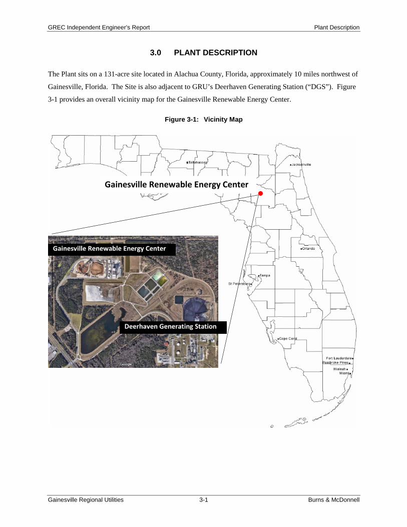
The Plant sits on a 131-acre site located in Alachua County, Florida, approximately 10 miles northwest of
Gainesville, Florida. The Site is also adjacent to GRU’s Deerhaven Generating Station (“DGS”). Figure
3-1 provides an overall vicinity map for the Gainesville Renewable Energy Center.
Figure 3-1: Vicinity Map
Gainesville Renewable Energy Center

GREC Independent Engineer’s Report Plant Description
Gainesville Regional Utilities 3-2 Burns & McDonnell
The Plant includes one 100 percent woody biomass bubbling fluidized bed (“BFB”) boiler with selective
catalytic reduction (“SCR”), baghouse, sorbent injection, zero-liquid discharge (“ZLD”), and a steam
turbine generator (“STG”). Figure 3-2 presents the site layout for the Plant.
Figure 3-2: Site Layout
3.1 General Introduction The Project is a nominal rated 102.5 MW net (116 MW gross) biomass-fired electric generating facility,
and consists of a biomass fuel handling system, a biomass-fired boiler and associated ash handling
systems and air quality control systems (“AQCS”), an axial exhaust condensing STG with evaporative
cooling tower, and auxiliary support equipment. Commercial operation was initiated in December 2013.
The Facility incorporates a ZLD system to eliminate industrial wastewater discharges pursuant to its
permits. The Project appears to have been designed in accordance with power industry standards,
therefore with standard O&M practices its technical service life should achieve at least 30 to 40 years of
service.
The Project utilizes a Metso (now Valmet) HYBEX BFB boiler with sodium bicarbonate injection to
produce superheated steam. A baghouse is included to control particulate matter (“PM”). The 19 percent

GREC Independent Engineer’s Report Plant Description
Gainesville Regional Utilities 3-3 Burns & McDonnell
aqueous ammonia injection SCR system that follows the baghouse provides additional NOx control.
Superheated steam from the boiler is sent to a single Siemens STG with four feedwater heating
extractions. The steam turbine generates electricity before exhausting axially into a two-pass condenser,
with its cooling water provided by a five-cell wet evaporative cooling tower.
Electric power is produced by the STG at a nominal voltage of 13.8 kilovolts (“kV”). A two-winding
generator step-up (“GSU”) transformer at the on-site substation increases the voltage to 138 kV which
then connects through aerial transmission lines to the interconnection point with GRU’s looped 138 kV
transmission system. Station service (“SS”) power is fed back through a dedicated SS transformer also
located within the on-site substation.
The Project, as presented in Figure 3-1, is located within the confines of GRU’s existing Deerhaven
Power Plant site on property leased from the City of Gainesville (d/b/a GRU). GREC indicated GRU has
title to 100 percent of the Plant’s output, including all environmental attributes (such as renewable energy
credits, carbon offsets, etc.).
GREC purchases biomass feedstock for fuel generally from within a 50 to 55-mile radius of the site
(urban wood waste, as described below, has a larger economical radius, approximately 75 miles or more
in some cases). The primary fuels for the Project are wood and wood waste from the following
categories:
• In-woods – represents over 80 percent of fuel supply to the Plant over the past 4 years and
consists of wood from agricultural and forestry land management activities including site
preparation, fire fuels reduction, salvage, and land clearing.
• Mill residue – represents approximately 5 to 10 percent of the fuel supply over the past 4 years
and consists of waste from primary and secondary wood mills.
• Urban – approximately 10 percent of the fuel supply to the Plant over the past 4 years and
consists of curbside yard/storm debris, tree service and land-clearing debris.
Wood is delivered in chipped and sawdust form with a maximum size of 6 inches (“in”) nominal, with
small amounts of sawdust and fines. The Facility is not designed to burn treated wood nor any other solid
or liquid fuels. Natural gas provides start-up fuel to the unit. Natural gas cannot be used as a primary/low-
load fuel due to the location of the gas burners at the boiler.
The BFB boiler produces up to approximately 930,000 pounds per hour (“lb/h”) superheated steam and
sends it to the Siemens STG. The STG is a single flow, single casing turbine with high pressure (“HP”)

GREC Independent Engineer’s Report Plant Description
Gainesville Regional Utilities 3-4 Burns & McDonnell
and low pressure (“LP”) sections and four extractions, and exhausts axially to the condenser. Condensate
is pumped to a gland condenser and on to the LP feedwater heater. The water from the LP feedwater
heater goes to the deaerator, where it mixes with the condensate from the steam coil boiler air heater and
LP steam. From the deaerator, the hot water is pumped by 2 x 100 percent ring section boiler feed pumps
supplied by Flowserve to two HP heaters and then is returned to the boiler.
Plant makeup water can be supplied from two full capacity on-site process wells, as well as reclaimed
water from the City of Alachua. The wells can provide the entire water needs for the Project; however,
reclaimed water is used as available, which is usually the case according to plant staff. Wastewater is
processed in the ZLD system. Wastewater from the Project is recycled or reused to comply with all
applicable permits.
Solid waste generated by plant operation include bottom ash, fly ash, and ZLD solids. The bottom ash
and ZLD solids are shipped off-site to be landfilled. The fly ash is also shipped off-site for beneficial re-
use.
3.1.1 Site Conditions The Project site is located east of U.S. Highway 441, south of Northwest 128th Lane, and west of the
Deerhaven Generating Station in Gainesville, Florida, as presented in Figure 3-1. GREC has leased
approximately 131 acres from GRU for the Project site. GREC indicated it has also obtained easements
to allow for the operation, and maintenance of the Project.
The main parcel of land consists of approximately 131 acres. The biomass Plant utilizes approximately
60 acres of the parcel. Electric power produced in the STG at the nominal generator voltage is increased
in voltage at an on-site substation and transmitted through aerial transmission lines to the interconnection
point with GRU’s looped 138 kV transmission system. GRU’s transmission system is interconnected
with Duke Energy and Florida Power & Light (“FP&L”).
The site, easements, and additional areas appear to be suitable for operation and maintenance of the Plant.
3.1.2 Civil & Structural Design GREC indicated that geotechnical subsurface investigations and studies were conducted prior to
commencement of construction. The soils at the site are a mixture of sands and potentially expansive
soils. Geotechnical soil test borings performed prior to construction found loose to medium dense sand
with silt to silty sand to a depth of approximately 10 feet followed by loose to medium dense clay sand to

GREC Independent Engineer’s Report Plant Description
Gainesville Regional Utilities 3-5 Burns & McDonnell
stiff sandy clay to a depth of approximately 40 feet. This type of soil is common in Florida, and typical
foundation construction methods were used during construction including:
• For shallow foundations, structures were supported on conventional shallow foundations, post-
tensioned slabs, or thickened edge monolithic slabs.
• For deep foundations, structures were supported on augured cast in-place (augurcast) piles or
drilled shafts for support of the heavily loaded structures.
• For large underground structures such as the truck tipper facility, structural slab systems in
conjunction with anchor drilled piers were used to resist buoyancy hydrostatic pressure due to
high groundwater.
• Pavements for roads and parking were designed as a function of the anticipated traffic loadings.
According to GREC, additional soils testing was performed prior to construction including electrical
resistivity imaging (“ERI”) investigation of the site to evaluate potential site specific geological
conditions (including potential for sinkholes). The focus of the investigation was on a 39-acre area of the
site that includes the power block equipment. According to GREC, the geotechnical engineer concluded
that the ERI test data are indicative of a stable geologic subsurface suitable for development, and none of
the data patterns were indicative of sinkhole activity or other unstable conditions.
A limited area of horizontally disparate resistivity was detected in the northeast portion of the site.
However, no major plant equipment was placed in this area.
Road designs appear to conform to Florida Department of Transportation requirements, with roads
surfaced with asphalt. According to information received from GREC, the road access from the highway
was widened and improved during construction. The existing turning lanes were lengthened to support
increased truck traffic (up to 150 to 160 trucks per day as reported by plant personnel when the Plant is
operating at full capacity). Roads, drives, and surfaced areas are well maintained and suitable for Project
operation.
According to GREC, the structural design of the power plant was done in accordance with State of
Florida Building Code and the International Building Code, 2006 edition. The structural design is
suitable and consistent with good engineering practice. GREC indicated that based on geotechnical
investigations, deep foundations using drilled piers or augured cast-in-place piles were utilized to support
heavy structures, while spread or strip type footings were utilized for light structures.

GREC Independent Engineer’s Report Plant Description
Gainesville Regional Utilities 3-6 Burns & McDonnell
Steel structures are used throughout the Plant as needed. Structural steel is painted indoors and
galvanized outdoors, which is suitable per industry standards.
Hoists are located throughout the Plant to facilitate maintenance. Eight manually operated monorail chain
hoists are located within the Plant for maintenance and access to equipment such as boiler feed pumps,
circulating water pumps, condensate pumps, auxiliary cooling pumps, and wood yard hogs. Fourteen
(14) electric hoists are also provided for boiler equipment maintenance. No permanent crane is provided
for the enclosed outdoor steam turbine, but rather adequate space is provided to allow servicing by means
of mobile cranes. The number and location of hoists are well suited to the Plant maintenance needs.
3.2 Power Block The Plant consists of one Valmet (formerly known as Metso) BFB boiler, Wolf biomass storage and
handling equipment, one Siemens condensing STG, and auxiliary equipment including a cooling tower,
well pumps, water treatment equipment, and air compressors. The Plant has a nominal net capacity of
102.5 MW.
3.2.1 BFB Boiler Technology Description Metso (now incorporated into Valmet) engineered, procured, manufactured, and delivered the BFB boiler
for the Project. BFB combustion for power generation has been around since the mid-1980s. Metso
developed HYBEX in the 1990s, a proprietary technology for BFB boilers suitable for a wide range of
fuel moistures, as suits biomass facilities, with biomass fuels often having high moisture content. The
HYBEX system also includes the patented “Hydro Beam” floor grate for easy removal of coarse material
from the furnace.
Metso has installed or converted more than 200 HYBEX boilers worldwide, and was well qualified to
design and construct the BFB boiler. BFB boilers are well suited to handle fuels with low heat value and
high moisture content. The boiler overall constructive simplicity, together with the turbulent, low
temperature bed and the ability to regulate the fluidization velocity and secondary and tertiary air
quantities, gives the BFB fuel flexibility, good combustion efficiency (about 90 percent), and low
emissions.
A BFB boiler consists of natural sand in a fluidized air suspension at the bottom of the boiler. Larger fuel
particles and residual char burn within the bed, while smaller particles burn above it. The combustion is
sustained and controlled with fluidizing (primary) and over-fire (secondary and tertiary) air. The
fluidizing bed benefits from a large combustion zone and high turbulence, allowing efficient solid-to-gas
contact and high heat transfer rates. The over-fire air completes the combustion and regulates oxygen

GREC Independent Engineer’s Report Plant Description
Gainesville Regional Utilities 3-7 Burns & McDonnell
content in the flue gas, thereby regulating emissions. The Metso design also includes a tall furnace for
prolonged mixing and combustion duration. A fuel gas recirculation fan sends cooler flue gas back into
the furnace to help with temperature control along.
The boiler is designed to burn forest residue, mill residue, pre-commercial tree thinnings, used pallets,
and clean urban wood waste including woody tree trimmings that are generated by landscaping
contractors, power line clearance contractors, and other non-forestry related sources of woody debris.
The BFB technology can handle a wide variation in wood supply, and is generally considered very fuel
flexible. The boiler also uses natural gas as an auxiliary fuel for startup, utilizing four burners to get the
sand bed to a minimum temperature of 900°F. The boiler system by design produces approximately
930,000 lb/h of superheated steam at 1,620 pounds per square inch gauge (“psig”) and 1,005°F, with
feedwater provided to the boiler economizer at 440°F.
The plant design fuel range includes moisture contents from 40 percent to 50 percent. The BFB
technology can accommodate moisture contents above and below this range as well. Changes in moisture
content should not impact output, but will impact heat rate.
The boiler system receives fuel via two metering bins, with a total storage capacity of approximately 45
minutes. Each bin delivers the fuel to three metering screws via drag conveyors. From the metering
screws, the fuel is delivered to fuel chutes connected to the furnace.
Typical fluidization velocities are low, which minimizes sand loss in normal operation. Most of the sand
losses are through the coarse material removal system, while a minor amount breaks into finer particles
and is carried by the flue gas. Reclaimed and makeup sand for the boiler is housed in a sand silo and is
fed to the boiler by gravity through a rotary valve feeder connected to a chute.
Primary air (fluidizing air) is introduced into the furnace by the primary air fan. This air is heated with a
flue gas air heater before being introduced into the furnace through evenly spaced fluidizing air nozzles
penetrating the floor. Over-fire air, to complete the combustion process, is introduced into the furnace by
the secondary air fan. This air is heated by auxiliary steam and four stages of flue gas. Over-fire air is
separated into two flows: a secondary and a tertiary stage. The secondary and tertiary airflows are
delivered to the furnace through constant velocity nozzles located at the front and rear walls.
The post-combustion gases (flue gas) leave the furnace after reaching the radiant superheater section on
top of the boiler, which enables steam production. From there the flue gas flows through a second and
third superheater surface to sustain this process. After its passes through the superheaters, the flue gas

GREC Independent Engineer’s Report Plant Description
Gainesville Regional Utilities 3-8 Burns & McDonnell
flows through the finned tube economizer bundles to heat the water in preparation for steam generation.
The residual heat in the flue gas is then used to condition the combustion air via primary and secondary
tubular air heaters, which increase the efficiency of the boiler. In addition, after passing the boiler
economizer, dry sorbent injection is used to control flue gas hydrogen chloride (“HCl”), hydrogen
fluoride (“HF”), and sulfur oxides (including sulfur dioxide (“SO2”) and sulfur trioxide (“SO3”). The
cooled gas finally reaches the baghouse filter for removal of airborne particles, and from there it is routed
back through an additional stage of air heaters and then the flue gas is treated by a SCR system using 19
percent aqueous ammonia injection to reduce NOx emissions. To maintain appropriate flue gas
temperature into the SCR, steam coil air preheaters are used to increase boiler inlet air temperatures for
part load and cold ambient conditions.
After passing through the SCR, the flue gas is ducted to the stack via a single induced draft fan located
downstream, which maintains flue gas pressure in the furnace at approximately -0.02 pounds per square
inch absolute (“psia”).
The boiler includes a HYBEX floor grate design, which has a cooling effect on the ash and allows for
more than 30 percent of the floor to remain open for ash removal. The coarse material (bottom ash) falls
from the bed into a system of ash hoppers, conveyors, and chutes that ends in an ash container. Fly ash is
collected at three points in the flue gas system: the second pass hopper, the third pass hopper, and the
baghouse. Ash collected during the second and third pass is carried to the handling system via a screw
conveyor. The baghouse includes a pulse jet type online cleaning system that collects fly ash in the
baghouse hoppers.
Boiler emissions are controlled by regulating available oxygen during combustion and using a post-
combustion SCR system with catalyst bed and ammonia injection. The boiler design also includes dry
sorbent flue gas cleaning to remove acid gases. Sodium bicarbonate sorbent is injected after the
economizer into the baghouse to control HF, HCl, and SO2/SO3. Table 3-1 lists equipment included with
the boiler that was furnished by Metso.

GREC Independent Engineer’s Report Plant Description
Gainesville Regional Utilities 3-9 Burns & McDonnell
Table 3-1: Major Boiling System Equipment
Equipment Bubbling Fluidized Bed Boiler Drum, furnace, superheaters, steam attemperators, economizer bundle with headers, structural supports, and boiler casing. Combustion Air System (a) Primary (fluidizing) air system including one air fan, silencer, inlet vane flow control, and
ducting with air heater, fuel feed and ammonia system. (b) Secondary (Burner/Over fire) air system including one variable frequency controlled air fan,
silencer, and ducting with air heater, constant velocity nozzles, and cooling air piping for main flame scanner.
Flue Gas System Primary air tubular air heater, secondary air tubular air heater, flue gas ductwork, pulse jet baghouse, induced draft fan, and insulated carbon steel flue gas stack. Flue Gas Recirculation (FGR) System One Flue gas recirculation fan with inlet vane flow control and ducting. Fuel Feed System Two metering bins totaling approximately 45 minutes of storage capacity, including rotating screw reclaimers, two drag chain conveyors, six metering screws, six rotary airlocks, fuel chutes, and structure. Sand Feed System One sand storage silo with pneumatic fill line, vent piping, and structure. Screw conveyor discharge with feed chutework. Coarse Material Handling System Twelve removal hoppers with manual and pneumatic isolation gate valves, three water cooled screw conveyors, one drag conveyor with multiple inlets, and a material sieving and recirculation system. Fly Ash Handling System Two second pass ash hoppers, one third pass hopper with two motor driven screw conveyors, one ash transfer screw, and multiple bag filter hopper outlet connections. Vacuum conveying system consisting of common conveying line, filter separator, two vacuum blowers, two silo fluidizing blowers, bin vent filter, pugmill and dry unloading spout. Burners Four natural gas fired startup burner assemblies. SCR System Vanadium pentoxide based catalyst bed, one forwarding skid, including two piston type metering pumps, ammonia valve racks, and ammonia injection manifolds. Two bed locations are included for redundancy. Deaerator One 20-minute deaerator with storage tank and supporting steel. Other Distributed Control System (DCS), transmitters, and elevator.
GREC Independent Engineer’s Report Plant Description
Gainesville Regional Utilities 3-10 Burns & McDonnell
3.2.2 Steam Cycle Description The steam cycle includes a single flow turbine operating at 1,590 psig, with 1,000°F steam temperatures.
The turbine exhausts steam to a water-cooled condenser at a design back pressure of 2.5 inches of
mercury absolute (“in. HgA”). Waste heat is rejected from the steam cycle through a plant common
closed loop circulating water system to a five-cell mechanical draft cooling tower.
Condensate from the condenser hot well is forwarded to the boiler through a gland condenser and a four-
heater feedwater heating system. The condenser is equipped with two 100 percent capacity condensate
hot well pumps that pump through the gland steam condenser. Water is forwarded from the gland
condenser to the feedwater heating system. The feedwater heating system consists of one closed LP
heater, one open deaerating heater, and two closed HP heaters. The steam cycle equipment is designed
for constant pressure operation. Two 100 percent motor driven ring section Flowserve boiler feed pumps
deliver feedwater to the HP section of the steam cycle. The overall arrangement and common equipment
features are good practice for a utility quality power plant.
The feedwater system consists of four feedwater heaters: one LP heater, one deaerator, and two HP
heaters. All heaters receive steam supplied from steam turbine extraction points.
Two 100 percent Flowserve condensate pumps are provided. Condensate pump discharge flows through
the gland steam condenser, the LP feedwater heater, and into the open deaerator. The condensate flow
leaving the deaerator is forwarded by one of two 100 percent capacity Flowserve boiler feed pumps. One
boiler feed pump provides full load capability for the Plant, with the second boiler feed pump on standby.
The discharge of the boiler feed pumps flows through the two HP feedwater heaters to the boiler.
The feedwater and condensate systems include adequate redundancies that will allow continued operation
in the event of a component failure.
The heat rejection system for the Plant is comprised of a Holtec single two-pass surface condenser,
circulating water system, cooling tower, and closed-loop auxiliary cooling system. Two 75 percent
capacity circulating water pumps circulate water through the condenser. The circulating water pumps are
low temperature, low pressure, high flow vertical pumps that are typically highly reliable. The single
pump capacity of 75 percent was selected to ensure that one pump is sufficient to sustain operation at the
minimum 70 MW output required by the PPA.

GREC Independent Engineer’s Report Plant Description
Gainesville Regional Utilities 3-11 Burns & McDonnell
The circulating water pumps take suction from the cooling tower basin and discharge to a common header
routed to the condenser. After the circulating water has cooled and condensed steam within the surface
condenser, it is returned to a common header that is directed back to the cooling tower.
The two-pass divided water box condenser is designed to maintain turbine back pressure at or below 2.5
in. HgA, with STG valves wide open. The circulating water flow rate through the condenser is based on
the valves wide open condenser duty and a wet-bulb temperature of 78°F. Condenser tubes and tube
sheets are 317SS stainless steel, which should afford them good reliability.
The Evaptech mechanical draft, counterblow cooling tower rejects the heat from the condensers and
auxiliary cooling water system. The design wet-bulb temperature is 78°F. One of the five cooling tower
cells can be removed from service for maintenance and testing without affecting plant output.
3.2.3 Steam Turbine and Generator The STG was designed, manufactured, and delivered by Siemens. Siemens has more than 20,000
installed steam turbine units through more than 100 years of experience and continuous development.
According to information received from GREC, for SST-700 and STT-900 turbines of the industrial size
class, Siemens counts over 280 installations since 1974. The unit installed at GREC is an SST-900,
which includes over 60 installations worldwide.
The steam turbine is a model SST-900 single casing steam turbine designed for 115,900 kilowatts (“kW”)
of gross capacity, operating at 3,600 revolutions per minute (“rpm”) with direct drive to the generator.
The SST-900 units are built from a series of standardized sections and modules, which allows the blade
lengths and number of stages to be customized to specific project requirements. The unit includes a
symmetrical casing, a simple single valve inlet instead of a valve chest, axial condensing exhaust, and
four bleed ports for feed water heating. Its relatively small dimensions on the hot path components and
consequent smaller thermal inertia allow this condensing turbine to accept shorter start-up times and
quicker load changes. The STG is installed outdoors in a full enclosure.
The STG design conditions include 910,100 lb/h flow at 1,590 psia and 1,000°F at the inlet, with 628,005
lb/h at 1.227 psia condensate exhaust flow after feedwater heating extractions.
STG major maintenance is on a 60,000-operating-hour cycle, which would be every 8 years at base load
operation. Since the Plant has operated for a total of about 4,000 hours since the commercial operation
date (“COD”), STG major maintenance will not be required for several more years. Its need should be re-
evaluated as more operating experience is gained.
GREC Independent Engineer’s Report Plant Description
Gainesville Regional Utilities 3-12 Burns & McDonnell
Siemens provided a BRUSH DAX two-pole air-cooled cylindrical rotor generator. The BRUSH DAX
units have been extensively used with industrial and aeroderivative gas turbines, as well as with steam
turbine applications. The generator is 60 hertz (“Hz”) three-phase and designed to operate at a 0.85
(lagging) power factor at 13.8 kV, with output of 116.45 MW (or 136.59 megavolt ampere (“MVA”)).
The cooling circuit forces air around the generator through two axial flow fans on the rotor shaft. The air
is cooled by a water-cooled heat exchanger.
3.2.4 Emissions Control The Plant controls NOx emissions in the boiler using both Low NOx burners and over-fire air.
Exhaust from the boiler passes through a baghouse for removal of fly ash. Downstream of the baghouse,
exhaust gas enters the SCR and NOx emissions are further reduced. The SCR in this case is a low-dust
design, located downstream of a baghouse, to potentially mitigate the concern of catalyst deactivation
from alkalines in the biomass ash. Nineteen (19) percent aqueous ammonia is used as the reagents for
NOx reduction. Ammonia is injected into the ammonia injection grid (“AIG”) upstream of the statis
mixers and flow straightening devices. Catalyst replacement can be scheduled to coincide with major
scheduled outage of the Plant so there will be no impact on the overall availability.
A dry sorbent injection (“DSI”) system is used in the unit to remove SO2. The sodium bicarbonate
injection is used to reduce acidic gas emissions, such as for HF and HCl as well.
3.3 Material Handling
3.3.1 Fuel Conveying The biomass fuel handling system consists of unloading, screening/hogging, stackout/storage, reclaim and
feed sub-systems.
The unloading system consists of three hydraulic truck tippers, dust collection, and unloading belt
conveyor. Fuel delivery trucks are received at a 135-ton capacity truck scale to register the entering
weight and other information via radio frequency identification (“RFID”) tag. After weighing, the trucks
proceed around the wood yard to the truck unloading enclosure (near the main entrance to the Plant). The
unloading structure consists of three 60-ton drive-through dumpers allowing simultaneous delivery of up
to three truckloads. After unloading, the trucks are weighed again to register the amount of wood
delivered. Each unloading hopper is equipped with dual spike rolls as well as in-situ moisture
measurement. The unloader hoppers each discharge to a common 72” unloading belt conveyor. The
GREC Independent Engineer’s Report Plant Description
Gainesville Regional Utilities 3-13 Burns & McDonnell
conveyor includes a magnetic separator and a metal detector for removing tramp material. The hoppers as
well as the conveyor load points are equipped with dust collection provided by a baghouse style dust
collector located outdoors near the conveyor exit tunnel. A rotary feeder and screen conveyor return the
collected wood dust to the unloading belt conveyor, downstream.
From the fuel receiving hoppers, the unloading conveyor delivers fuel to the screening/hogging building
at 600 short tons per hour (“tph”). The screening/hogging system reduces oversized fuel to 2.5” or smaller
sizes. There are two disc screen/hog trains, each with 300 tph capacity. The hogs have a design capacity
of 100 tph each; this is sufficient due to the amount of undersized material separated by the screens. Both
trains include a 54” belt conveyor to feed a common stackout transfer conveyor rated at 600 tph. The
common 72” belt conveyor feeds Transfer Tower #1, to divert fuel to either of the two stackout systems.
The stackout system includes an automatic circular stacker/reclaimer system and a manual telescoping
chute stackout system. The circular stacker/reclaimer has approximately 270º degrees of rotation. It
forms a kidney-shaped pile and consists of a luffing and slewing boom belt for stackout and a luffing and
slewing chain reclaim system. The telescoping chute boom is fixed (no luffing/slewing capability). Dust
suppression spray water is applied prior to loadout through the chute to reduce fugitive dusting.
The two fuel storage piles have a collective storage capacity of 243,300 cubic yards (approximately
59,122 tons or 20 days at full load) and are separate from each other, isolated by transfer conveyors. The
fuel piles are not typically segregated by wood supply, but are segregated to maintain first-in, first-out
fuel inventory practices. Wood/sawdust from various sources is passively blended in the
unloading/stackout systems. Two in-ground chain reclaimers are used to provide mobile-equipment
assisted reclaim (via two Wagner rubber-tired chip dozers) from either of the two stackout piles. All
reclaim systems feed a series of 48” reclaim belt conveyors to transfer to the unit feed belt, Conveyor 9, at
Transfer Tower #2. The reclaim and feed conveyors are designed for 250 tph capacity but are typically
run at 200 tph per discussion with plant personnel.
The 48” feed conveyor from Transfer Tower #2 is equipped with a belt-rip detection system two drives
(one redundant) for added reliability. The conveyor is equipped with dust collection at the head of the
conveyor (combined with the collection from the metering bin which it feeds). The discharge chutework
includes a motor-operated splitter gate to feed the first metering bin, and/or another 48” transfer belt
conveyor to feed the other bin. Wolf’s scope of supply ended at the chutework interface to the metering
bins. The metering bin/boiler feed system was furnished by Raumaster Oy, a supplier under Metso
contract.

GREC Independent Engineer’s Report Plant Description
Gainesville Regional Utilities 3-14 Burns & McDonnell
Each metering bin includes a screw reclaim system, drag chain conveyor with balancing pocket,
feed/robbing screw conveyors and three rotary valve/feed chutes. The system is illustrated on Figure 3-3,
and is followed by a more detailed description of this process in Table 3-2.
Figure 3-3: Material Handling System Flow

GREC Independent Engineer’s Report Plant Description
Gainesville Regional Utilities 3-15 Burns & McDonnell
Table 3-2: Conveyors of the Material Handling System
Conveyor Size Material
Size General Description Width Capacity No. 1 72 inches 600 tph 6 inches From the In-Pit Receiving Hoppers to splitting
bins No. 2 54 inches 300 tph 2.5 inches Provides approximately 12'-0 inch of vertical lift.
From one (1) of the Screen/Hogs to Conveyor No. 4
No. 3 54 inches 300 tph 2.5 inches Provides approximately 12'-0 inch of vertical lift. From one (1) of the Screen/Hogs to Conveyor No. 4
No. 4 72 inches 600 tph 2.5 inches Provides approximately 80'-0 inch of vertical lift. From Conveyors No. 2 and 3 to either Conveyor No. 5 or 6
No. 5 72 inches 600 tph 2.5 inches Provides approximately 46'-9 inch of vertical lift. From Conveyor No. 4 to Stacker/Reclaimer No. 1
No. 6 72 inches 600 tph 2.5 inches Provides approximately 29' of vertical lift. From Conveyor No. 4 to stockpile
No. 7 48 inches 250 tph 2.5 inches Provides approximately 13'-0 inch of vertical lift. From the Stacker/Reclaimer to Conveyor No. 8 or from Underpile Reclaimer No. 1 to Conveyor No. 8
No. 8 48 inches 250 tph 2.5 inches Provides approximately 13' of vertical lift. From Conveyor No. 7 to Conveyor No. 9
No. 9 48 inches 250 tph 2.5 inches Provides approximately 121'-9 inch of vertical lift. From Conveyor No. 8 or Conveyor No. 11 to Conveyor No. 10 or Boiler Feed Silo 1
No. 10 48 inches 250 tph 2.5 inches From conveyor No. 9 to Boiler Feed Silo 2. No. 11 48 inches 250 tph 2.5 inches Provides approximately 13' of vertical lift.
From Underpile Reclaimer No. 2 to Conveyor No. 9
In comparison to the fuel handling system design conveying capacities, the boiler will require a full load
fuel input of approximately 134 tph (assuming 90 percent availability). The material handling system’s
design includes adequate unloading and feed rate multipliers (600 tph and 250 tph respectively) for a
woody-biomass-fired power facility, allowing the system to be operated less than full time during the
week. The conveying and processing equipment capacities, yard layout, and storage quantities are
considered reasonable.

GREC Independent Engineer’s Report Plant Description
Gainesville Regional Utilities 3-16 Burns & McDonnell
The design truck dump rate of six trucks per hour per truck dumper (a total of 18 trucks per hour) is
achievable but not probable to be maintained for any long period of time. A more realistic unload rate of
four trucks per hour per truck dumper or total of 12 trucks per hour provides more than 300 tph (assuming
25-ton capacity per truck) in comparison to the full load requirement of 134 tph.
From discussions with plant personnel, the majority of OEM troughing idlers have been replaced
(approximately 90 percent) due to bearing failure. Burns & McDonnell assumes that these issues are due
to manufacturing defects and not overall system design issues. The problematic idlers have been found
throughout the wood handling system and have been replaced with Joy Global brand sealed-for-life idlers.
No subsequent issues have been reported.
Minor modifications to the spike roll systems at the unloading hoppers have improved unloading
operations.
No other non-trivial issues with the material handling system were reported during the site visit. Burns &
McDonnell believes the wood yard material handling system has been adequately designed to meet the
Plant’s biomass fuel needs for continuous full load operation and is in-line with margins at other facilities.
3.3.2 Ash Collection and Storage Biomass fuel sources are inherently low in ash, and, therefore, small quantities are generated during
operation. Nevertheless, a collection and storage system supplied by Allen-Sherman-Hoff is installed for
both the bottom ash and fly ash generated by the BFB boiler and emissions control equipment. A vacuum
pneumatic system collects fly ash from sections of the boiler and the baghouse hoppers. Fly ash is
conveyed to a steel storage silo designed for a minimum of 4 days of storage at full load. Fly ash is
discharged through a telescopic dry unloader and pug mill for disposal or sale by truck. Bottom ash,
which is limited in quantity, is removed from the bottom of the boiler and collected in custom roll-off
bins for periodic removal. ZLD system solids are also collected and hauled off-site by truck for disposal.
3.4 Water Supply and Treatment Water supply is from two on-site wells, and recycled water from the City of Alachua. The wells can
provide the entire water needs for the Project, however, reclaimed water is used as available. Well water
and recycled water is stored in the 1,000,000-gallon raw water/fire water tank. A separate 50,000-gallon
tank stores well water which is used for service water and for supply to the cycle makeup treatment
system.

GREC Independent Engineer’s Report Plant Description
Gainesville Regional Utilities 3-17 Burns & McDonnell
The cycle makeup treatment system provides high purity water to the plant steam cycle as makeup. The
treatment process is a reverse osmosis (“RO”)/electro-deionization (“EDI”) configuration with two 100
percent trains. This treatment technology is considered proven and is typical for this application. The
cycle makeup treatment system receives water from the well water storage tank. The initial treatment
step utilizes ultrafiltration membranes to remove particulates from the well water. The RO then removes
a significant portion of the ionic load, thereby reducing the burden on the EDI system, which polishes the
processed water. The cycle makeup treatment, along with inlet ultrafiltration, is an appropriate means of
producing demineralized water.
Potable water is obtained from a separate dedicated water well for treatment and distribution on-site.
3.5 Wastewater Treatment Systems
3.5.1 Process Wastewater The Plant water systems are designed to minimize water use and maximize recycling and reuse using a
ZLD system. The ZLD includes a brine concentrator and crystallizer. Process wastewater from the steam
cycle makeup treatment system and steam cycle blowdown is routed to the cooling tower basin for reuse.
Cooling tower blowdown is treated in the ZLD system with product water returned to the cooling tower.
ZLD solids residue is produced in the crystallizer and disposed of in a landfill. The ZLD system to be a
typical means to implement zero discharge requirements for power plants.
3.5.2 Potentially Oily Wastewater All equipment and floor drains, potentially contaminated with oil, are routed through an oil/water
separator prior to collection in the plant wastewater sump. The wastewater sump discharges to the
cooling tower basin. This system is a typical means to remove oils that can be found in plant wastewater
streams.
3.5.3 Sanitary Wastewater The sanitary wastewater is collected via a network of gravity drain piping, and transferred to an on-site
sewer lift station where waste water is pumped to the DGS sanitary system that discharges to the city
sewer system.
3.6 Plant Electrical Systems Power generated in the Plant’s electric generator is transformed to 138 kV via a three-winding GSU
transformer. The power from the GSU transformer is delivered to GRU’s 138 kV transmission system
that connects the facility to the Florida Reliability Coordinating Council, Inc (“FRCC”) system.

GREC Independent Engineer’s Report Plant Description
Gainesville Regional Utilities 3-18 Burns & McDonnell
The electrical system includes auxiliary electric systems, as well as high voltage systems to export power
to GRU. The electrical equipment manufacturers, types, styles, and ratings are consistent with industry
practice and appropriate for use in power plants.
3.6.1 Auxiliary Electric System The auxiliary electric distribution system for the Plant consists of equipment that operates at nominal
voltages of 4.16 kV, and 480 volts (“V”). The auxiliary electrical system design is considered appropriate
and allows for the use of typical electrical distribution equipment.
The Facility does not have “black start” or “islanding mode operation” capabilities. The facility startup
and backup power is back-fed from the 138-kV system through the station service transformer. If the
138-kV power system is not available, or power supply to the system is lost, a standby diesel engine
generator provides standby power to supply housekeeping auxiliary loads. The auxiliary electric system
is considered typical for a plant of this size and type.
3.6.2 Generator Step-Up Transformer The Pennsylvania Transformer GSU transformer increases voltage provided by the STG to the 138-kV
transmission system. The GSU transformer is a 13.8 kV to 138 kV, two-winding, ONAN/ONAF/ONAF,
104/138/173 MVA, three-phase, delta-wye, 60 Hz, 65 C rise transformer. The transformer is installed
outdoors, and is an oil-filled type equipped with standard accessories and oil spill containment provisions.
3.6.3 Station Service (SS) Transformer The SS transformer is also an outdoor type with standard accessories. The SS transformer supplies power
for the plant auxiliary loads. The transformer is 138 kV to 4.16 kV, three-phase, 60 Hz, delta-wye 65 C
rise transformer. The SS transformer and the GSU transformer are both connected to a 138-kV radial bus
via their respective 138 kV breakers.
The SS transformer supplies power for auxiliary loads during startup, shutdown, and normal operations.
3.6.4 Direct Current and Critical Alternating Current Systems All critical instrumentation, control, and monitoring circuits required for startup, on-line operation,
shutdown, and off-line operation of the Facility are supplied either by a battery connected direct current
(“DC”) system or uninterruptible power supplies (“UPS”).
The 125 V DC battery system is sized to supply a minimum of 8 hours for critical DC loads. Each 125 V
DC battery charger is sized to fully recharge the batteries from a fully discharged condition in less than 15

GREC Independent Engineer’s Report Plant Description
Gainesville Regional Utilities 3-19 Burns & McDonnell
hours while maintaining the continuous normal steady-state loads. Equipment sensitive to incoming
power quality is fed from the UPS.
3.6.5 Grounding, Lighting, and Cathodic Protection Systems Grounding, lightning, and cathodic protection systems are provided as needed within the Plant.
3.7 Transmission & Electrical Interconnection The 138-kV plant switchyard is arranged in a radial bus configuration with two 138-kV circuit breakers.
One 138-kV circuit breaker is connected to the high side of the GSU transformer. The other 138 kV
circuit breaker is connected to the high side of the SS transformer. A 138-kV transmission line exits the
138-kV plant switchyard to terminate at GRU’s 138-kV Switching Station at the point of interconnection.
The plant switchyard configuration is considered typical for application in a facility of this type and size.
The switchyard equipment and materials were designed in accordance with applicable codes and
standards. The switchyard equipment ratings are considered sufficient to facilitate full evacuation of
output from the project.
The Project is interconnected to GRU’s 138-kV Lines 21 and 22 via the 138 kV Switching Station. The
interconnection point between the Project and GRU’s 138-kV Switching Station is where the Project’s
jumper conductors connect with GRU’s transmission line conductors on the Project’s dead-end structure
located adjacent to the Switching Station.
The Plant is responsible for ownership of the estimated 4,500 feet of single-circuit transmission line from
the plant’s 138-kV switchyard to the Project’s dead-end structure located just outside of the GRU 138-kV
Switching Station. This transmission line includes fiber-optic cable that is used for primary and
redundant line relaying schemes.
3.8 Balance of Plant and Operation Systems
3.8.1 Fire Protection Considerations The fire protection system for the Plant is designed in accordance with NFPA (“National Fire Protection
Agency”)850 “Recommended Practice for Fire Protection for Electric Generating Plants and High-
Voltage Direct Current Converter Stations.” The plant fire water supply system includes one 100 percent
electric motor driven pump and one 100 percent diesel engine driven pump. Both pumps take suction
from the 1 million gallon raw water storage tank, with 250,000 gallons dedicated to fire water service.

GREC Independent Engineer’s Report Plant Description
Gainesville Regional Utilities 3-20 Burns & McDonnell
These pumps provide water to the fire protection system equipment. A jockey pump is used to maintain
system pressure. Fire protection provisions are customary for a unit of this size and configuration.
3.8.2 Balance-of-Plant Mechanical Systems The mechanical balance-of-plant (“BOP”) systems are of conventional design and are provided with
redundant capacity appropriate for power generation service. Installed spare capacity based on the
percentage of the total plant requirement is presented in Table 3-1.
Table 3-3: BOP System Summary
System Manufacturer Equipment Installed Capacity
Compressed Air Atlas Copco Compressors 2 x 100% Circulating Water Flowserve Pumps 2 x 75% Closed Cooling Alfa Laval and Flowserve Heat Exchangers and Pumps 2 x 100% Condensate Flowserve Pumps 2 x 100% Fire Protection WW Gay Pumps 2 x 100% Boiler Feed Flowserve Pumps 2 x 100%
3.9 Instrumentation and Control System The overall plant instrumentation and control system includes a distributed control system (“DCS”)
provided by Metso. The DCS is a microprocessor-based integrated control and data acquisition system
providing control and monitoring of plant equipment from the central control room. The system consists
of distributed processors and controllers, interconnected with all controller elements via a redundant
switched Ethernet data highway.
All instrumentation and systems were designed to provide safe and reliable operation of the Plant in
accordance with applicable codes and standards. In addition, the system was designed to follow all
applicable National Electric Reliability Council (“NERC”) and National Institute of Science and
Technology (“NIST”) cyber security requirements.
The instrumentation and control systems are appropriate for a plant of this type and size. The system
should enable plant personnel to safely operate and monitor the performance of plant systems and
components from the main control room.
GREC Independent Engineer’s Report Operations & Maintenance Practices
Gainesville Regional Utilities 4-1 Burns & McDonnell
4.0 OPERATIONS & MAINTENANCE PRACTICES
The following section summarizes the O&M practices for GREC.
4.1 Operating Philosophy The Plant entered commercial operation in December 2013. The Plant has a PPA with GRU. Burns &
McDonnell did not review the PPA as part of this Study, however, based on discussions with GREC,
GRU will schedule the dispatch of the Plant under the PPA and receive both the capacity and energy from
the Plant to meet its load obligations.
4.2 Plant Operations & Performance The Plant is operated and maintained by NAES Corporation. Based on review of the data provided, the
existing facility appears to be in good condition. The plant layout is typical for a facility of this type and
size.
Plant personnel indicated there were two issues in the material handling system that have now been
resolved: 1) hot spots within the fuel yard and 2) smoldering fuel within the hogger. The Plant
implemented procedures to curtail the potential for hot spots within the fuel yard including better fuel
segregation using a first-in, first-out policy and it now monitors pile temperatures twice per day. The fuel
smoldering caused no damage to the equipment as it was contained within the hogger, but a lot of smoke
was produced. The fire department was called because of the excessive amount of smoke in the building
above the hogger (plant personnel are not trained in the use of self-contained breathing apparatus
(“SCBA”) and did not want to endanger anyone). There has been no additional fire suppression added
since the plant completion. Following these procedural changes, Plant management indicated the
Gainesville fire department inspector was satisfied with the wood yard based on the location of hydrants
and that the insurance inspectors from AIG were also satisfied and have not made any requests for
modifications.
Review of the documentation and discussions with plant personnel revealed that no abnormal conditions
were detected that would prevent continued service.
4.2.1 Plant Staffing EMI has contracted operation and maintenance activities for both the Plant and fuel supply to NAES and
BRM, respectively. A total of 39 employees currently make up the staff of NAES for GREC. BRM has a
staff of four (4) employees dedicated to GREC. NAES provides all things necessary for the proper
operation and maintenance of the Plant including day-to-day operation and maintenance, long-term

GREC Independent Engineer’s Report Operations & Maintenance Practices
Gainesville Regional Utilities 4-2 Burns & McDonnell
maintenance planning, spare parts management, and other responsibilities required to maintain the
Facility in proper working order.
In addition to the NAES staff, four employees are contracted through BRM for fuel management and
procurement. The four employees consist of a Fuel Procurement Manager, Biomass Forester, Quality
Control Technician, and Scale Attendant. BRM is charged with the following tasks:
• Development and maintenance of fuel supply chain, fuel delivery scheduling and preparation of
fuel payments
• Operation of scales, ticketing system, and facilitation of truck dump operation.
• Fuel quality control oversight including in-house analysis of fuel moisture and ash content.
• Oversight of forest-sourced fuel Minimum Sustainability Standards (“MSS”)
• Forest Stewardship Council (“FSC”) Controlled Wood and Chain of Custody certification
maintenance.
The organizational structure of the Plant is included in Figure 4-1. The overall staffing of the Facility
appears to be similar to other biomass projects within the industry.
Figure 4-1: Gainesville Renewable Energy Center Organizational Structure
OwnerEnergy Management Inc.
GREC O&MNAES Corp.
Fuel ProcurementBioResource Management
(BRM)
Plant ManagerSteve Marsh
Maintenance Planner (1)
Operations SupervisorMichael Buonsignore
IC&E Technician(3)
Warehouse Assistant (1)
Administrative Assistant (1)
Plant EngineerAli Leaphart
Maintenance SupervisorTommy Gardner
Office SupervisorLorie Thebaut
Maintenance Technician (4)
Water Treatment Operator (4)
Fuel Yard Operator (8 to 10)
Auxiliary Plant Operator (8)
Lead Control Room Operator (4)

GREC Independent Engineer’s Report Operations & Maintenance Practices
Gainesville Regional Utilities 4-3 Burns & McDonnell
4.2.2 Plant Operating Statistics Burns & McDonnell reviewed several key operating statistics to evaluate the overall reliability,
utilization, and performance of the Plant.
Figure 4-2 presents key availability statistics for GREC from 2014 through 2017 regarding equivalent
availability factor (“EAF”) and equivalent forced outage rate (“EFOR”).
Figure 4-2: Plant Equivalent Availability Data for 2014 through 2017
As presented in Figure 4-2, both the EAF and EFOR were lower and higher, respectively, in 2014.
However, this was the first year of operation and power plants typically experience lower reliability as the
plants work through commissioning and problematic issues with the initiation of systems. The
availability of the Facility dramatically increased from 2015 to 2017 and has been above 90 percent in
each of these years. The EFOR in 2016 was elevated due to the low number of service hours for the unit
since it was in a long-term layup status.
Figure 4-3 presents the net generation and net capacity factor for GREC from 2014 through 2017.

GREC Independent Engineer’s Report Operations & Maintenance Practices
Gainesville Regional Utilities 4-4 Burns & McDonnell
Figure 4-3: Plant Net Generation and Net Capacity Factor Data
The Plant was anticipated to operate as a baseload facility and have a high capacity factor when it was
initially developed. However, the electric generation industry has seen a reduction in the price of
wholesale power largely due to lower natural gas prices and more efficient combustion turbines. As such,
the Plant has generated less energy recently and has been placed in long-term standby several times. The
Plant was on stand-by for a significant portion of 2016. However, in 2017 the Facility was dispatched by
GRU after the long stand-by period, and was able to start and reliably provide power after the extended
layup.
From the NERC generating availability data system (“GADS”), solid-fuel facilities of similar size
generally have availability factors in the 85 to 88 percent range, however this data includes facilities with
a range of ages and technologies. Relative to other facilities of similar size, the Plant has experienced
above average availability factors. Database research of similar biomass facilities in the southeastern
U.S. indicted an average capacity factor of approximately 60 percent.
4.2.3 Thermal Performance As previously discussed, the Plant has a PPA for electrical production which has cost and performance
parameters associated with the delivery of electricity (the specific agreement was not reviewed as part of
this Study). The performance of the Plant is important to assess its ability to provide efficient energy for
GRU to meet its load obligations.

GREC Independent Engineer’s Report Operations & Maintenance Practices
Gainesville Regional Utilities 4-5 Burns & McDonnell
Burns & McDonnell reviewed the performance tests provided by GREC at the commissioning of the
Facility and subsequent performance evaluations. The performance test, conducted by McHale &
Associates Inc. (“McHale”), compared the guaranteed performance against the actual performance
experienced during the test. After the performance test, McHale concluded that the results indicated that
the plant performance passed for both electrical output and heat rate guarantees. Table 4-1 presents the
results from the McHale report summarizing the Plant performance test at commissioning. While the
corrected plant electrical output falls slightly short of the guaranteed plant electrical output, McHale
indicated that it was within an acceptable range for the results accuracy.
Table 4-1: Summary of Plant Performance Test at Commissioning
Note: The performance test was corrected using requirements associated with the original contract between GREC and the Plant engineer/construction contractor at the time of commissioning.
Most recently, GREC performed its dependable capacity claim test as defined within the PPA. This claim
test was conducted on May 29, 2017. EMI reported the Facility operated at an average output of 103.05
MW over a 12-hour operating period. Based on both the claim test information and McHale’s
performance test, the Facility appears to be able to produce over 101.5 MW (net) as designed.
According to GREC, the minimum operating output for GREC is 70 MW as defined within the PPA.
Burns & McDonnell inquired with the staff whether the Facility would have the ability to operate at a
lower turndown point than is currently defined within the PPA. GREC indicated the Facility is limited to
a technical turndown point of approximately 60 MW due to a backend temperature requirement located at
the injection point of the SCR. The injection point of the SCR requires a minimum effective temperature
of 375°F. If the unit is operating at less than approximately 60 MW, the backend temperature drops

GREC Independent Engineer’s Report Operations & Maintenance Practices
Gainesville Regional Utilities 4-6 Burns & McDonnell
below 375°F and the SCR becomes ineffective. The installation of duct burners, heating coils, or an
economizer bypass could be investigated as means to increase the overall temperature at lower load
points, however this may require a modification to the air permit.
Figure 4-4 presents the average net plant heat from 2014 through 2017.
Figure 4-4: Plant Net Heat Rate for 2014 through 2017
As presented in Figure 4-4 the net heat rate for the Plant was considerably higher in 2016 compared to
other years. This was due to the limited number of service hours in 2016. The overall heat rate fluctuated
between 12 to 14 MMBtu/MWh for the other years of operation. Heat rates for biomass plants are
heavily dependent on the fuel quality. The heat rate for the Facility appears to be similar to other biomass
power plants of comparable size and age.
Figure 4-5 presents the monthly burn rate of fuel from 2014 through 2017 on a tons per generation
(tons/MWh) basis.
13.4614.19
16.49
12.17
0
2
4
6
8
10
12
14
16
18
2014 2015 2016 2017
Net
Hea
t Rat
e (M
MBt
u/M
Wh)
Annual Average Net Heat Rate (MMBtu/MWh)

GREC Independent Engineer’s Report Operations & Maintenance Practices
Gainesville Regional Utilities 4-7 Burns & McDonnell
Figure 4-5: Plant Fuel Burn Rate for 2014 through 2017
As presented in Figure 4-5, the burn rate of fuel measured as tons/MWh have typically fluctuated between
1.2 to 1.4 tons/MWh. In months where generation was limited, the overall burn rate was significantly
higher, reflecting the similar trend to the overall heat rate.
4.3 Fuel Supply During the site visit, BRM provided a presentation summarizing the fuel supply and management for
GREC. GREC receives three main fuel types consisting of in-woods, urban, and mill residues. GREC
has over 20 fuel suppliers and producers supplying the various fuel types. This includes seven (7) in-
woods producers with the remainder consisting of urban producers. The average haul distance for in-
woods fuel deliveries is between 50 to 55 miles, urban deliveries can be farther. Table 4-2 presents the
typical fuel characteristics according to BRM.
0
0.2
0.4
0.6
0.8
1
1.2
1.4
1.6
1.8
Janu
ary
Febr
uary
Mar
chAp
rilM
ayJu
ne July
Augu
stSe
ptem
ber
Oct
ober
Nov
embe
rDe
cem
ber
Janu
ary
Febr
uary
Mar
chAp
rilM
ayJu
ne July
Augu
stSe
ptem
ber
Oct
ober
Nov
embe
rDe
cem
ber
Janu
ary
Febr
uary
Mar
chAp
rilM
ayJu
ne July
Augu
stSe
ptem
ber
Oct
ober
Nov
embe
rDe
cem
ber
Janu
ary
Febr
uary
Mar
chAp
rilM
ayJu
ne
2014 2015 2016 2017
Burn
Rat
e (T
ons/
MW
h)
Monthly Fuel Burn Rate (Tons/MWh)

GREC Independent Engineer’s Report Operations & Maintenance Practices
Gainesville Regional Utilities 4-8 Burns & McDonnell
Table 4-2: Typical Fuel Characteristics
Type Moisture Content (%)
Ash Content (%)
Heat Content (Btu/dry lb)
In-woods 36% - 42% < 2% 8,450
Urban 25% - 45% 2% - 10% 8,200
Mill residues (dry) 12% < 1% 9,100
Mill residues (green) 45% - 52% < 1% 9,100
Overall, BRM estimates there is greater than 5 million acres of timberland within GREC’s supply shed
generating greater than 7 million tons of conventional roundwood products. Logging residues and other
agricultural land management activity generates greater than 1 million tons of fuel wood. Urban
resources account for approximately 700,000 tons of wood waste within an economic haul distance of
approximately 50 miles. Mill residues generate approximately 2 million tons of potential fuel supply.
While there are competing uses for these wood products, the supply of wood waste appears to be
sufficient to maintain GREC’s operation based on BRM’s experience.1 Table 4-3 and Figure 4-6 present
the historical fuel sourcing for GREC. As illustrated in the table and figure, a large majority of the
biomass fuel has historically come from in-woods resources.
Table 4-3: Historical Fuel Sourcing (tons)
Year In-woods (tons)
Urban (tons)
Mill Residue (tons)
Total (tons)
2014 526,085 196,074 39,346 761,505
2015 394,738 44,536 36,134 475,408
2016 37,299 2,071 17,540 56,910
2017 181,819 15,904 6,837 204,560
1 Burns & McDonnell did not complete an independent evaluation of the fuel supply availability in the area.

GREC Independent Engineer’s Report Operations & Maintenance Practices
Gainesville Regional Utilities 4-9 Burns & McDonnell
Figure 4-6: Historical Fuel Sourcing (tons)
BRM indicated that fuel delivery costs are a function of the type and quality of wood, distance hauled,
diesel fuel prices, moisture content, and the overall dispatch characteristics of the Plant. BRM indicated
that most fuel is procured on a dry weight basis (i.e. price is adjusted for moisture content). Additionally,
fuel supply contracts typically contain adjusters for diesel fuel prices and are invoiced based on the
distance that the fuel is hauled. Urban fuel suppliers typically have price adjusters for the percentage of
ash content in the fuel. Table 4-4 presents the historical fuel costs for GREC.
69%83% 83% 89%
5%
8% 8%3%26%
9% 9% 8%
0%
10%
20%
30%
40%
50%
60%
70%
80%
90%
100%
2014 2015 2016 2017
Perc
ent o
f Tot
al Su
pply
Fuel Supply SourceIn-woods Mill residue Urban

GREC Independent Engineer’s Report Operations & Maintenance Practices
Gainesville Regional Utilities 4-10 Burns & McDonnell
Table 4-4: Historical Fuel Costs
4.4 Non-Fuel O&M Expenses EMI provided a discussion of the O&M expenses that have been historically incurred and an overall
summary budget for the Plant operating in both a long-term layup status and dispatched at baseload.
Table 4-5: O&M Budget Summary
Note: Labor/Staffing presented above are considered fully burdened costs including payroll, employee benefit, and tax expenses.
Category
Fuel Delivered
(tons)Moisture
Content (%)
Fuel Delivered (dry tons)
Fuel Delivered (MMBtu)
Delivered Fuel Costs ($)
Delivered Fuel Cost
($/ton)
Delivered Fuel Cost ($/dry ton)
Delivered Fuel Cost ($/MMBtu)
In-woods 526,085 39% 319,694 5,402,834 $14,052,102 $26.71 $43.95 $2.60Mill residue 39,346 41% 23,348 424,932 $1,054,055 $26.79 $45.15 $2.48Urban 196,074 39% 119,293 1,956,404 $4,710,047 $24.02 $39.48 $2.41Total 761,505 39% 462,335 7,784,170 $19,816,204 $26.02 $42.86 $2.55
2015In-woods 394,738 39% 239,439 4,046,513 $10,423,918 $26.41 $43.53 $2.58Mill residue 36,134 39% 22,221 404,419 $964,620 $26.70 $43.41 $2.39Urban 44,536 38% 27,507 451,120 $1,060,456 $23.81 $38.55 $2.35Total 475,408 39% 289,167 4,902,052 $12,448,994 $26.19 $43.05 $2.54
2016In-woods 37,299 41% 21,880 369,780 $1,071,341 $28.72 $48.96 $2.90Mill residue 17,540 38% 10,958 199,431 $551,831 $31.46 $50.36 $2.77Urban 2,071 34% 1,360 22,296 $57,431 $27.73 $42.24 $2.58Total 56,910 40% 34,198 591,507 $1,680,602 $29.53 $49.14 $2.84
2017In-woods 181,819 40% 109,709 1,854,078 $5,227,153 $28.75 $47.65 $2.82Mill residue 6,837 26% 5,050 91,904 $195,480 $28.59 $38.71 $2.13Urban 15,904 31% 11,027 180,836 $356,237 $22.40 $32.31 $1.97Total 204,560 39% 125,785 2,126,818 $5,778,870 $28.25 $45.94 $2.72
2014
2014
2015
2016
2017
Expense Category 2014 2015 2016Fixed Expenses
Labor/Staffing $4,500,000 $4,600,000 $4,300,000Fixed O&M $2,480,000 $2,560,000 $1,400,000Fuel Management $839,000 $539,000 $405,000
Total Fixed Costs $7,819,000 $7,699,000 $6,105,000Total Fixed Costs ($/kW-yr) $77.03 $75.85 $60.15
Variable ExpensesVariable O&M $2,880,000 $2,170,000 $966,000Major Maintenance $1,800,000 $1,700,000 $404,000
Total Variable Costs $4,680,000 $3,870,000 $1,370,000Total Variable Costs ($/MWh) $8.09 $11.20 $38.20
Total Non-Fuel Expenses $12,499,000 $11,569,000 $7,475,000

GREC Independent Engineer’s Report Operations & Maintenance Practices
Gainesville Regional Utilities 4-11 Burns & McDonnell
The total fixed O&M costs for GREC are approximately $6 million to $8 million per year, which equates
to approximately $60 to $75/kW-year when looked at on a per kW basis. This is slightly higher than
would be expected for a biomass facility of this type and size. Database research of similar biomass
facilities in the southeastern U.S. indicated an average total fixed O&M cost of approximately $32/kW-
year is typical. However, GREC has significantly more equipment installed than the typical biomass
facility consisting of the AQCS (SCR, baghouse, and DSI) and the ZLD system. This additional
equipment further increases the costs associated with O&M.
The variable O&M costs for GREC are approximately $8/MWh to $11/MWh and are within the range of
what would be expected for a biomass facility of this type. Database research of similar biomass facilities
in the southeastern U.S. indicted a range of non-fuel variable O&M costs of approximately $8/MWh.
4.5 Major Maintenance Burns & McDonnell reviewed the overall maintenance of the Facility and specifically some of the more
critical major maintenance activities. The following major maintenance projects were completed since
the Plant went into service.
• April/May 2015 Outage
o Before the October 2014 outage, the boiler’s tertiary superheater had experienced tube
failures at the weld of the tube stub to the header. This was investigated and found to be a
design issue. During the May 2015 outage, the header was replaced by Valmet under
warranty, and as a result Valmet extended the warranty of the boiler until May 2016. GREC
indicated there have been no further leaks.
o A design issue was addressed by Siemens under warranty in the STG single combined
steam admission and control valve, which was causing a control oil leak through the
valve stem, and large oscillations in generator output at high power. There had been
several outages before to replace the seal, which kept deteriorating and leaking. The
permanent repair to the oil leak consisted of replacing the stem seal with a different
design. GREC reported there have been no subsequent leaks.
o The STG was experiencing a “flutter” in power output occurring between 90 MW and
full load, with cyclical power output swings of about 1.5 MW (e.g., at 95 MW the power
will swing between 93.5 MW and 96.5 MW). Obvious potential causes such as steam
supply, vacuum or control oil variations, were investigated and eliminated as the root
cause. The control valve was disassembled by Siemens during both the previous October

GREC Independent Engineer’s Report Operations & Maintenance Practices
Gainesville Regional Utilities 4-12 Burns & McDonnell
2014 outage and this outage, but no unusual conditions were found. According to plant
personnel this is still occurring at a reduced 0.75 MW range, which Siemens has stated is
within tolerance.
• In March 2017, Doble Engineering Company performed an electromagnetic interference
diagnostic testing of the generator, isolated phase bus systems, and transformers, and found that
the generator had questionable results, indicating that a problem is present or developing.
o High radiated electromagnetic interference levels were noted at the generator connection box.
They recommended inspecting the connections for looseness, proper assembly, and torque
during the next scheduled maintenance period. According to EMI, during the May outage
GREC inspected and re-torqued all connections in the connection box. Some bolts had not
met torque requirements.
o Very high radiated electromagnetic interference levels were noted from the lube oil piping at
the turbine. Static discharges in lube oil systems can cause oxidation of the oil and result in
oil breakdown and contamination. They recommended that an oil analysis be conducted, and
if the oil is darkened and breaking down the source of the static discharges should be
resolved. According to EMI, after investigation into the problem and discussions with other
users of gas and steam turbines that experienced this type of static discharge a solution was
found. GREC determined the resolution for this issue is using low static oil filters to
eliminate the static discharge. GREC has been sampling turbine generator lube oil monthly
and has not observed any degradation. GREC indicated that if degradation of oil quality is
observed, then it plans to purchase and install electrostatic discharge resistant filters.
• June 2017 Outage
o The GSU was tested by Electrical Reliability Services and found to have unacceptable
moisture content in the oil for the type and class of transformer. They recommended oil
resampling every three months. The Plant has been in long term layup since then. GREC did
resample the oil in the GSU and the moisture level was acceptable. GREC indicated that
regular oil sampling is part of its preventative maintenance program.
o Seven flexible duct connections around the boiler begun to have cracks, with one leaking. All
seven were replaced with higher quality material.
o In other findings, batteries and catalyst were tested and found to be in good condition.
In addition to the major maintenance items above, the Plant has installed or modified a few other items of
note:

GREC Independent Engineer’s Report Operations & Maintenance Practices
Gainesville Regional Utilities 4-13 Burns & McDonnell
• Due to frequent extended layups, a permanent nitrogen (N2) generator for boiler blanketing
during layups was installed during the fall outage of 2016 on Level 8 of the boiler.
• A noise reduction liner clad in stainless steel was installed in the stack shortly after plant startup
to eliminate low frequency noise at a nearby residential subdivision.
• An odor control system was installed on the west side of the biomass fuel yard to help eliminate
unpleasant odors.
• The Plant utilizes a “snow maker” style mist system to help control dust at the fuel yard.
4.6 Spare Parts Inventory Burns & McDonnell reviewed and discussed the spare parts inventory with the plant staff. It appears the
Plant has sufficient spare parts to maintain reliable operation. Major spare parts include a replacement
belt for Conveyer 9 which feeds the power block and is considered the single point of failure for the
material handling system. Additionally, GREC owns three large fan motors in dry storage in Jacksonville
for the induced draft fan, primary air fan, and flue gas recirculation fan. Other major spares include
rotary feeders, screws, impellers, valves, and bearings. Overall, the spare parts inventory has a cost of
approximately $4 million.

GREC Independent Engineer’s Report Key Contracts and Agreements
Gainesville Regional Utilities 5-1 Burns & McDonnell
5.0 KEY CONTRACTS AND AGREEMENTS
Burns & McDonnell reviewed several of the agreements that GREC currently has in place for operating
the Plant. EMI indicated that the proposed structure of the sale was an asset sale, so some, if not all, of
these agreements would be contingent on GRU and the other parties agreeing to assign the contracts from
GREC to GRU. To the extent possible, Burns & McDonnell reviewed the contracts that GREC has in
place; however, these may be subject to change based on negotiations between GRU and the
counterparties. Furthermore, due to confidentiality concerns some of the specific pricing information was
redacted within the agreements. However, the key terms were available for review against industry
standards regarding technical/engineering operations.
5.1 Biomass Services and Fuel Management Agreement GREC has a biomass services agreement in place with BioResource Management, Inc. Due to
confidentiality concerns, Burns & McDonnell was provided a redacted version of the biomass services
agreement, but key terms were reviewed. The following summarizes the key provisions of the biomass
services and fuel management agreement.
• The initial term of the agreement is effective through December 31, 2019. Unless terminated in
accordance with the agreement, the term will automatically renew for successive three-year
periods.
• BRM shall supply the services related to the procurement, delivery and management of biomass
used by GREC at the Facility.
• BRM is paid 1) a monthly management fee and 2) costs on a monthly basis for actual expenses
incurred (without markup). The monthly management fee is adjusted each calendar year to
movements in the Consumer Price Index.
• BRM does have the ability to receive an annual incentive payment as determined by a percentage
of the difference between the fuel reimbursement amount less the actual fuel costs (the actual
percentage was redacted).
• GREC or BRM may terminate the agreement with 60 days written notice prior to the end of a
term (or extension).
• GREC may terminate the agreement 1) at any time during the term or extension for break or
default by BRM or 2) upon providing 90 days prior written notice at any time.
• Either party may assign its rights and obligations under the agreement to an affiliate. Any party
may assign its rights and obligations under the agreement to any entity acquiring all or
substantially all of the business, assets, or outstanding voting interests. Neither party may assign

GREC Independent Engineer’s Report Key Contracts and Agreements
Gainesville Regional Utilities 5-2 Burns & McDonnell
any of its rights or obligations under the agreement without the prior written consent of the other
party.
• The agreement contains biomass specifications that require BRM to procure biomass 1) from
specific resource categories, 2) with specific size parameters, and 3) reasonably free of
incombustible material and unfluidized particles.
• BRM is to provide the following services:
o Biomass delivery and receipt: Coordination of truck receiving and sampling
o Biomass billing and payments: Maintain documentation of deliveries, generate invoices,
facilitate timely and accounts payments to suppliers by coordinating with GREC, maintain
contract requirements with suppliers, and communicate directly with suppliers regarding
issues associated with deliveries, billings, or payments.
o Biomass testing and analysis: Coordinate with operator of the Facility regarding testing of
biomass samples for moisture content, particle size, and other appropriate protocol (such as
ash content) and prepare and ship samples for testing.
5.2 Fuel Supply Agreements GREC (“Buyer”) has several biomass supply agreements in place with various suppliers (“Seller”). Due
to confidentiality concerns, Burns & McDonnell was provided redacted versions of several fuel supply
agreements. While specific costs and names were redacted, the overall general terms and conditions were
reviewed against typical industry standards.
The following summarizes some the key provisions of the fuel supply agreements in general, some of the
specific terms may vary slightly from contract to contract.
• Biomass shall be freight-on-board to the delivery point of Buyer. Seller shall pay all carting,
storage and transportation costs incurred in the shipment including all freight, loading, insurance
and other charges.
• Seller shall grant Buyer access to all processing sites for inspection. Buyer has the right to
conduct both announced and unannounced inspections as it sees fit.
• Buyer, at its sole option, may choose to not compensate Seller for Biomass that does not comply
with the terms and conditions. Buyer may also suspend deliveries from Seller for a period of no
less than one year if seller is found to be in non-compliance with MSS.
• Buyer has the right to reject any and all deliveries that do not meet the specifications.
• Both Seller and Buyer may assign the agreement to an affiliate or acquiring entity with written
consent from the other party, in which such consent shall not be unreasonably withheld.

GREC Independent Engineer’s Report Key Contracts and Agreements
Gainesville Regional Utilities 5-3 Burns & McDonnell
• Seller shall provide 60-days written notice of, and reasons for, termination of the agreement.
• The agreements include exhibits regarding biomass specifications, best management practices
requirements, and compensation.
• Biomass specifications
o The agreements outline the type of biomass that is acceptable for delivery (depending on the
supplier), including urban and/or forest produced biomass.
o Moisture content will be determined for each delivered load in the Facility receiving bins by
infrared measurements or other measurement methods as determined by the Buyer.
o General/example specifications for urban biomass delivered to Buyer shall meet the
following specifications:
− Biomass shall contain less than 1/10th of 1 percent foreign material. Delivered loads with
visible plastic film may be rejected.
− Biomass shall be sized so that at least 95 percent by weight will pass through a 2.5-inch
round screen; less than 1 percent by weight shall be greater than 8 inches in any
dimension.
− Biomass shall be sized so that no more than 18 percent by weight will pass through a
0.124-inch round screen.
− Biomass shall not contain more than 6 percent ash content as determined on a dry weight
basis, on average, for all deliveries each month; Delivered loads exceeding 12 percent ash
on a dry weight basis may be rejected.
o General/example specifications for forest produced biomass delivered to Buyer shall meet the
following specifications:
− Biomass shall contain less than 1/10th of 1 percent foreign material such as rock.
− Biomass shall be sized so that at least 95 percent by weight will pass through a 2.5-inch
round screen; no particles shall be greater than 6 inches in any dimension;
− Biomass shall be sized so that no more than 25 percent by weight will pass through a
0.124-inch round screen
− Biomass shall contain less than 2.5 percent to 4 percent (depending on the contract) ash
content, including non-combustible inert materials, as determined on a dry weight basis.
• Best management practices and minimum sustainability standards
o The agreements have an exhibit that address requirements for best management practices and
the minimum sustainability standards for both urban and forest produced biomass.

GREC Independent Engineer’s Report Key Contracts and Agreements
Gainesville Regional Utilities 5-4 Burns & McDonnell
o Overall, the agreement entails that the suppliers must meet many requirements regarding the
procurement of biomass resources including, but not limited to, environmental, legal,
planting, harvesting, and record keeping practices.
• Compensation
o The biomass price consists of the following components:
− Cut and process price
• Stumpage allowance ($ per dry ton)
• Process allowance ($ per dry ton)
• Off-road fuel allowance (gallons fuel per dry ton)
− Freight price
• Non-fuel freight allowance ($ per loaded mile)
• On-road fuel allowance (gallons fuel per loaded mile)
o Fuel allowances are determined each calendar month and adjusted based on the U.S. Energy
Information Administration’s East Coast Lower Atlantic Region.
o Stumpage allowance is adjusted by a stumpage index which is defined as the quarterly
percent change in the average price of hardwood and softwood pulpwood stumpage prices as
reported by an index mutually agreed by the Seller and Buyer (the specific index was
redacted).
o Compensation is based on dry tons, therefore the Sellers are incentivized to deliver lower
moisture biomass.
5.3 Reclaimed Water Supply Memorandum of Understanding A Reclaimed Water Supply Memorandum of Understanding (“MOU”) was executed by and between
GREC, the City of Gainesville, Florida (d/b/a GRU), the City of Alachua (“City”), and the Suwannee
River Water Management District (individually known as “Party” or collectively known as the “Parties”).
The MOU implements the terms and conditions that the Parties will use to promote the use of Reclaimed
Water at the Facility and thereby reduce the use of groundwater. As a Party to the MOU, it is anticipated
that GRU will be assigned and responsible for GREC’s portion of the MOU.
Key terms of the MOU are as follows:
• Several terms of the MOU were applicable to the Plant while it was under development and/or
construction, including the following:
o The City will use best efforts to identify and obtain state, federal, and other grants to pay the
capital costs associated with the construction of the proposed water pipeline that will connect

GREC Independent Engineer’s Report Key Contracts and Agreements
Gainesville Regional Utilities 5-5 Burns & McDonnell
the City’s Reclaimed Water system to the Facility. Any costs not covered by grants will be
paid for by GREC and/or GRU.
o The City’s proposed pipeline routing shall be determined by the City (with consultation by
GREC and GRU) and the selected routing shall be the lowest cost alternative when evaluated
considering the anticipated capital, operating, maintenance, permitting, and other costs
associated with the construction and operation of the City’s proposed pipeline.
o The City shall construct, own, operate, and maintain the pipeline needed to transport the
Reclaimed Water to the Point of Interconnection.
• The City has the right to provide its Reclaimed Water to the City’s other customers and has the
right to determine when and how much of the City’s Reclaimed Water will be available to the
City.
• Prior to GREC using groundwater, GREC shall use the maximum amount of Reclaimed Water
feasible.
• GREC LLC shall pay to the City a reasonable usage charge per thousand gallons (“kgal”) for the
Reclaimed Water, which shall be the total of the following.
o The actual or mutually agreed upon estimate of the cost incurred by the City to operate and
maintain the facilities required to provide the Reclaimed Water to the Energy Center.
o The actual or mutually agreed upon estimate of the cost incurred by the City to maintain,
repair, renew, and replace, as necessary, the facilities used to provide the City's Reclaimed
Water to the Energy Center.
o The City's usual and customary overhead expense percentage, which shall include the transfer
of funds from the City's Wastewater Collection and Treatment Division, Public Services
Department to the City's General Fund, and which shall be applied as a percentage to the sum
of items.
• The City expects to be able to provide approximately 0.4 to 0.6 million gallons per day (“MGD”)
of the approximate 1.4 MGD the Facility will require.
• Since the usage charge is not specifically defined or limited by the Agreement, GREC does have
some financial risk for the cost of the reclaimed water, particularly since they are obligated to
purchase the reclaimed water. However, the Parties have agreed to review the usage calculations
and use an independent engineer to evaluate disputes.
• As part of the permitting process, GRU agreed to decrease their groundwater withdrawals by an
equivalent amount to GREC’s groundwater withdrawals.
• The American Renewables personnel indicated that GRU has agreed to this provision, and could
reduce their water withdrawals as needed.

GREC Independent Engineer’s Report Key Contracts and Agreements
Gainesville Regional Utilities 5-6 Burns & McDonnell
• The MOU shall remain in effect for the life of the Plant. The MOU also may be amended or
renewed and extended with the written consent of the Parties.
5.4 Operations & Maintenance Agreement GREC (“Owner”) and NAES Corporation (“Operator”) have a contract for the operation and maintenance
of a biomass-fired power production facility dated June 14, 2011. EMI provided a redacted version of the
agreement due to confidentiality concerns. The following provides a summary of the key provisions of
the agreement.
• The Operator provides all things necessary for the proper operation and maintenance of the Plant
under the O&M Agreement.
• The term of the agreement is six years from the date of commercial operation. The first contract
year began on the date of commercial operation and ended on December 31 of the same year.
Each consecutive contract year begins on January 1 and ends on December 31. From that point
on, the contract term automatically renews every five years, unless written notice is given six
months prior to the end of a term.
• The O&M Agreement may be terminated at any time due to an event of default by either party.
The Owner may terminate the agreement for convenience at any time with 90 days’ written notice
to Operator.
• The Operator receives a base Management Fee as well as a Bonus Fee from the Owner. The
Operator is also subject to pay Liquidated Damages to the Owner. The exact amount of each fee,
as well as the Bonus and Damages cap has been redacted from the document.
• The Operator is reimbursed for all Direct Costs reasonably incurred in the performance of the
O&M Services, in addition to the Base Fee and any Bonus Fees. These include Project Work
Force compensation; materials, supplies, consumables, and other expenditures relating to the
operating, and maintenance costs of the Project, including the costs of all parts and equipment;
services provided by subcontractors and many administrative costs, such as accounting fees and
other professional services required to comply with this agreement.
• In addition to the payments mentioned above, the Owner is subject to a late-fee, according to the
“Late Payment Rate” which means, in relation to any period for which a late payment charge may
be incurred under this Agreement, the prime rate as announced from time to time by the Bank of
America plus two percent calculated based on a 365-day year and compounded monthly
Based on a review of the O&M Agreement, Burns & McDonnell concludes the following with respect to
future risks/issues:

GREC Independent Engineer’s Report Key Contracts and Agreements
Gainesville Regional Utilities 5-7 Burns & McDonnell
• The O&M Agreement contains standard industry terms and conditions.
• The Plant does not appear to have any technical limitations that would prevent it from meeting
the requirements of the O&M Agreement.
• The Operator is a qualified third-party operator of power generation facilities.
• The Management and Bonus Fees, although redacted for this review, appear to be clearly defined.
• The performance criteria required are clearly defined within the Appendices of the O&M
contract.
5.5 Power Purchase Agreement GRU and GREC have a PPA in place. Burns & McDonnell did not review the PPA as it was outside of
the scope of work for this Study.
5.6 Interconnection Agreement GREC and GRU indicated that the Plant currently has an interconnection agreement with GRU. It is
assumed that after the sale of the Facility, GRU would control the interconnection agreement. Burns &
McDonnell did not review the interconnection agreement as it was outside the scope of work for this
Study.
5.7 Lease Agreement GREC and GRU indicated that GREC currently has a lease agreement with the City of Gainesville (d/b/a
GRU). It is assumed that after the sale of the Facility, GRU would control the lease agreement. Burns &
McDonnell did not review the lease agreement as it was outside the scope of work for this Study.
5.8 Natural Gas Supply GREC and GRU indicated that GREC currently has an agreement to receive natural gas supply from
GRU. It is assumed that after the sale of the Facility, GRU would control the natural gas supply. Burns
& McDonnell did not review the natural gas supply agreement as it was outside the scope of work for this
Study.

GREC Independent Engineer’s Report Environmental Review
Gainesville Regional Utilities 6-1 Burns & McDonnell
6.0 ENVIRONMENTAL REVIEW
Environmental studies, applications, and permit documents were reviewed, all or in part, as provided by
GREC. No fatal flaws were identified. Owners and operators should make themselves aware of all permit
conditions, paying particular attention to required notifications and expiration dates.
GREC prepared and submitted a Site Certificate Application (“SCA”) to the Florida Department of
Environmental Protection to obtain certification of the construction and operation of the power plant as
required under the Florida Electrical Power Plant Siting Act. The Siting Board (Governor and Cabinet)
approved certification on December 7, 2010, and the final order was issued on December 15, 2010.
Conditions of Certification (“COC”) PA 09-55 contain both general conditions and specific conditions,
which are reviewed below. In addition, the Facility is currently subject to multiple air, water and other
environmental regulations and/or permits. According to the plant personnel, the Facility is in material
compliance with the current environmental permits. Since the Facility is relatively new, the
environmental controls are also relatively new. As a result, the Facility appears to have a low likelihood
of near term additional environmental costs. This analysis assumes that the current attributes of the fuel
are not significantly changed in the future and the unit operating profile is similar to the past. The
following sections describe the specific environmental topics analyzed as part of this Study.
6.1 Air Quality The BFB boiler has a maximum steam production rate of 930,000 pounds per hour. Other emission units
at the Facility include: biomass fuel delivery, preparation, storage, and handling; ash handling, storage,
and shipment equipment; a mechanical draft cooling tower; a 1,220-horsepower (“hp”) emergency
generator engine; a 315-hp emergency fire pump engine; and an alkaline sorbent storage silo. The facility
is an electrical services plant categorized under Standard Industrial Classification No. 4911. The initial
construction of GREC was issued the Prevention of Significant Deterioration (“PSD”) permit # 0010131-
001-AC on December 28, 2010.
Based on the initial Title V air operation permit received February 11, 2014, the Facility is regulated as a
major source of hazardous air pollutants (“HAP”), because it is located at a major source of HAP (i.e.,
GRU DGS). The existing facility is a PSD major source of air pollutants in accordance with Rule 62-
212.400, Florida Administrative Code (“F.A.C.”)
Currently, DGS and GREC have separate Title V permits but are considered a single source for
permitting purposes. If GRU purchases GREC, the next Title V renewal or modification for DGS and for
GREC will roll both facilities into a single Title V permit.

GREC Independent Engineer’s Report Environmental Review
Gainesville Regional Utilities 6-2 Burns & McDonnell
GREC SO2 and NOx emissions were offset by permanent and enforceable reductions required at the
contiguous GRU DGS following installation and startup of new air pollution control systems in 2009.
6.1.1 Prevention of Significant Deterioration The initial construction of GREC was issued PSD permit # 0010131-001-AC on December 28, 2010. This
permit was found on line at the Florida Department of Environmental Protection’s (“FDEP”) website and
not in the data room. The permit was incorporated into the latest Title V permit, #0010131-006-AV.
6.1.2 Limits and Controls Table 6-1 summarizes the emission units and their requirements. Table 6-2 summarizes the limits for the
BFB boiler.
Excess emissions are limited as follows:
• Cold startup limited to 19 hours
• Warm/hot startup limited to 15 hours
• Shutdown limited to 3 hours in any 24-hour period
• The combined duration of excess emissions during cold startup, warm/hot startup, and shutdown
is limited to 340 hours during any consecutive 12-month period.

GREC Independent Engineer’s Report Environmental Review
Gainesville Regional Utilities 6-3 Burns & McDonnell
Table 6-1: Emission Units and Air Permit Requirements
Emission Unit
Number
Emission Unit
Description Requirements
001
Biomass fuel delivery, preparation, storage and handling
• Can operate continuously (8,760 hours/year). • The maximum designed hourly biomass processing rate is 600
tons per hour (tph) with a maximum designed yearly rate of 1,395,030 tons per year (tpy)
• Specifically prohibited from accepting biomass in the form of construction and demolition debris.
• Burns clean woody biomass • Conveyors must be enclosed where practical • A baghouse is used to control particulate matter (“PM”) emissions
from the screen/hog building. • A screw conveyor is installed to take the PM collected in the
baghouse to the conveyor taking the biomass fuel to the biomass fuel handling and storage system.
• Bin vent filters is used to control PM emissions from the metering bins for the BFB boiler
• Facility must follow Best Management Practices (BMP) plan to minimize fugitive dust from biomass handling and fugitive dust emissions from the Plant’s paved roadways and gravel areas
• 10% opacity limit for drop and transfer points. 5% opacity limit from screen/hog building baghouse and bin vent filters on metering bins. Monitoring is via Method 9
002
Nominal net 100 MW BFB, biomass fueled boiler
• Natural gas is used as a startup fuel for the boiler. • The maximum heat input capacity is 1,358 million British thermal
units per hour (MMBtu) per hour (4-hour average basis). • The maximum steam production capability is 930,000 pounds per
hour (lb/hr). • The maximum heat input capacity using natural gas is 341
MMBtu/hr during startup. • Subject to New Source Performance Standard (NSPS) Subpart
Da and National Emissions Standards for Hazardous Air Pollutants (NESHAP) Subpart DDDDD
• The hours of operation of this emission unit are not restricted (8,760 hours/year).
• Controls: baghouse, (SCR), in dust sorbent injection system for sulfur dioxide (SO2) removal
• SCR uses 19% ammonia; 15,000-gallon tank • Monitoring includes: bag leak detection; NOx, SO2, and carbon
monoxide (CO) continuous emissions monitoring system (“CEMS”); opacity continuous opacity monitoring system (“COMS”; pressure drop detection
• Subject to Acid Rain, Clean Air Interstate Rule (CAIR), and the Transport Rule Trading program

GREC Independent Engineer’s Report Environmental Review
Gainesville Regional Utilities 6-4 Burns & McDonnell
Emission Unit
Number
Emission Unit
Description Requirements
003
Ash handling, storage, and shipment
• The design maximum process throughput rates are 27,594 tpy of fly ash and 13,140 tpy of bottom ash
• The overall ash handling, storage and shipment system has a maximum annual design transfer rate of 40,734 tpy.
• Controlled by enclosure and bin vents/baghouses • The hours of operation of this emissions unit are not limited (i.e.,
unrestricted at 8,760 hours per year). • Opacity limits vary by equipment, monitored by Method 9 annual
compliance test • Method 5 test required annually on fly ash silo • PM emissions from the baghouse of the fly ash silo shall not
exceed 0.015 grains per dry standard cubic feet (gr/dscf).
004 Mechanical draft cooling tower
Unregulated
005
One emergency generator diesel engine
• Maximum design engine output rating of 315 hp (235 kilowatts [kW])
• NSPS Subpart IIII (Tier II emission limits) • Compliance with NESHAP Subpart ZZZZ met by complying with
NSPS Subpart IIII • 1,000-gallon fuel storage tank • Ultra-low sulfur diesel fuel • The emergency generator diesel engine may operate up to 100
hours per year for maintenance and testing purposes. There is no time limit on the use of emergency stationary internal combustion engines (ICE) in emergency situations.
006
315-hp emergency fire pump engine
• Maximum design engine output rating of 1,220 hp (910 kW) • NSPS Subpart IIII (Tier II emission limits) • Compliance with NESHAP Subpart ZZZZ met by complying with
NSPS Subpart IIII • Ultra-low sulfur diesel fuel • The emergency generator diesel engine may operate up to 100
hours per year for maintenance and testing purposes. There is no time limit on the use of emergency stationary ICE in emergency situations.
007 Alkaline sorbent storage silo
• Controlled by bin vent filter • The hours of operation of this emission unit are not restricted
(8,760 hours/year). • PM emission rate of 0.01 gr/dscf and opacity limited to 5% • Annual stack tests required (Method 5, 5B, 17, 9, 201, 201A)
GREC Independent Engineer’s Report Environmental Review
Gainesville Regional Utilities 6-5 Burns & McDonnell
Table 6-2: BFB Boiler Limits
Parameter Limit Basis Compliance
NOxa
1.0 pound per megawatt hour (lb/MW-hr) (gross basis)
NSPS Subpart Da 30-boiler operating day rolling average basis by CEMS
0.070 lb/MMBtu Applicant Request 30-boiler operating day rolling average basis by CEMS
416.4 tpy Emission Cap 12-month, rolled monthly by CEMS
SO2b
1.4 lb/MW-hr (gross basis) NSPS Subpart Da 30-boiler operating day rolling average basis by CEMS
0.029 lb/MMBtu Applicant’s Request 24-hour rolling by CEMS 170.7 tpy Emission Cap 12-month, rolled monthly by CEMS
SAMc 1.4 lb/hr Rule 62-4.070(3), F.A.C. Annual Stack Test
COd 0.08 lb/MMBtu BACT 30-day rolling by CEMS 310 ppmvd @3% oxygen (O2)
NESHAP Subpart DDDDD Annual Stack Test
HCle,f 2.22 lb/hr Applicant’s Request Stack Tests as Required by NESHAP Subpart
DDDDD 0.022 lb/MMBtu NESHAP Subpart DDDDD Annual Stack Test
HFe 2.22 lb/hr Applicant’s Request Stack Tests as Required by NESHAP Subpart DDDDD
Mercuryf 8.0 x 10⁻⁷ lb/MMBtu NESHAP Subpart DDDDD Annual Stack Test PM/PM10 (filterable)g
0.0098 lb/MMBtu BACT, NSPS Subpart Da NESHAP Subpart DDDDD
6-minute blocks by COMS
Visible Emissionsh 10% Opacity (20% once/hr) BACT Annual Stack Test VOC 0.009 lb/MMBtu BACT Annual Stack Test
NH3 Slipi 10 ppmvd @ 7% O2 Rule 62-210.650, F.A.C. Rule 62-4.070(3), F.A.C.
4-hour average, measured by the steam flow meter
Steam Production Rate 930,000 lb/hr Rule 62-210.200 (PTE), F.A.C. 30-boiler operating day rolling average basis by CEMS

GREC Independent Engineer’s Report Environmental Review
Gainesville Regional Utilities 6-6 Burns & McDonnell
Notes for Table 6-2: a. Emission cap for NOx ensures that GREC will not trigger PSD for this pollutant. b. Emission cap for SO2 ensures that GREC will not trigger PSD for this pollutant. c. Sulfuric acid mist (“SAM”) mass rate emission limit provides reasonable assurance that annual emissions will be less
than 7 tpy and PSD is not triggered for this pollutant. d. The NESHAP limit of 310 parts per million by volume dry (“ppmvd”) @3% O2 applies from the initial operation of the
boiler. e. The hourly limits for HF and HCl are imposed at the Applicant’s request. Compliance will be demonstrated with
annual stack tests. f. Hg and HCl limits for Subpart DDDDD compliance. However, if the performance tests for at least two consecutive
years show that the emissions are at or below 75 percent of the emission limit (or, in limited instances as specified in Tables 1 and 2 or 11 through 13 of Subpart DDDDD, at or below the emission limit) for the pollutant, and if there are no changes in the operation of the BFB boiler or air pollution control equipment that could increase emissions, GREC may choose to conduct performance tests for the pollutant every third year. Each such performance test must be conducted no more than 37 months after the previous performance test.
g. Filterable fraction as measured by EPA Method 5. The Subpart DDDDD 0.0098 lb/MMBtu limit will ensures compliance with the previous BACT and NSPS Subpart Da limit of 0.015 lb/MMBtu.
h. During startups, shutdowns and malfunction the following limits apply: 20% opacity (6-minute blocks) except for one 6-minute block per hour of 27%. Meeting this opacity standard provides assurance that the NSPS Subpart Da standard of no greater than 20 percent opacity (6-minute average), except for one 6-minute period per hour of not more than 27 percent opacity is met.
i. Ammonia (“NH3”) slip in parts per million by dry volume at 7% oxygen (ppmvd @ 7% O2).
6.1.3 Monitoring and Testing The BFB boiler stack shall be tested during each federal fiscal year (October 1st to September 30th) to
demonstrate compliance with the emission standards for NH3 slip, filterable PM, volatile organic
compounds (“VOC”), SAM, HCl (in units of lb/hr and lb/MMBtu), HF (in units of lb/hr), and opacity.
Compliance stack tests for HCl (in units of lb/MMBtu) shall be conducted as required by NESHAPs
Subpart DDDDD. Tests shall be conducted between 90 and 100 percent of the maximum permitted
capacity when firing woody biomass fuel. CEMS data for CO, NOx and SO2 along with COMS data for
opacity shall be reported for each run of the required tests for NH3, VOC, SAM, and PM. The BFB boiler
was required to have initial stack tests conducted for NH3, filterable PM (F), VOC, SAM, opacity, HCl,
and HF. The FDEP may require the permittee to repeat some or all of these initial stack tests after major
replacement or major repair of any air pollution control or process equipment.
Annual stack tests are required for fly ash silo and alkaline sorbent storage silo.
The Title V permit has an “Appendix BMP” which lists the Best Management Practices (“BMP”) plan for
minimization of fugitive dust, storage pile management and fire prevention. This document was found
online and not provided in the data room.
Performance tests were completed from March 22 to 24, 2017. The test program was used to determine
the compliance status of Woody Biomass-fueled BFB Boiler regarding its emissions limitations and
standards outlined in Air Construction Permit 0010131-006-AV and Industrial Boiler Maximum

GREC Independent Engineer’s Report Environmental Review
Gainesville Regional Utilities 6-7 Burns & McDonnell
Achievable Control Technology (“IB MACT”) standards, 40CFR63, Subpart DDDDD. Results were well
below all limits. A relative accuracy test audit (“RATA”) was also completed from March 21 to 22, 2017
with passing results.
6.1.4 National Ambient Air Quality Standards (“NAAQS”) The draft “Technical Evaluation & Preliminary Determination” was found on line and not in the data
room. This document discusses the air dispersion modeling that was conducted for the initial construction
of the Facility. PM10 and carbon monoxide (“CO”) were modeled; PM10 was used as a surrogate for
PM2.5. CO impacts were below the significance level. PM10 impacts were in compliance with the
NAAQS and PSD Increments. Impacts on the nearby Class I areas were below the allowable increment.
PM2.5 modeling may be required in the future if additional construction is undertaken at this or another
nearby facility. Additionally, 1-hour SO2 modeling may be required for NAAQS demonstration purposes.
6.1.5 Industrial Boiler MACT The limits imposed on the BFB Boiler by the IB MACT (NESHAP Subpart DDDDD) are included in
Table 6-2.
6.1.6 Greenhouse Gas Emissions Greenhouse gases are not expected to be an issue for biomass facilities.
6.1.7 Appeals The permit issued in December 2010 was appealed in January 2011. A settlement was reached (March 4,
2011) with the appellants which required further conditions as outlined below. The settlement agreement
states that if the DEP fails to put these requirements into the PSD permit within 45 days, the conditions
are still effective. Condition 1.24 states that GREC shall request the permit modifications outlined in the
settlement to the FDEP within 30 days of the effective date. Below is detailed information about the
settlement.
6.1.7.1 Settlement Agreement On March 4, 2011, GREC entered into a settlement agreement with petitioners that had been challenging
the permit issuance for Facility. The agreement required:
• Allows the Alachua County Environmental Protection Division (“ACEPD”) access to CEMS
reports and to inspect the facility.

GREC Independent Engineer’s Report Environmental Review
Gainesville Regional Utilities 6-8 Burns & McDonnell
• Further inspections by the ACEPD for this facility, including surveys for wildlife, inspection of
the biomass and other environmental reasons for inspections.
• GREC must give $25,000 each year for the next six years (after formal Notice to Proceed
construction) to the ACEPD to assist in compensating the department for the inspections that they
will be performing on the Facility.
• GREC will comply with any MACT that is issued for this facility, including an IB MACT or
electrical generating unit MACT.
• GREC must pay the ACEPD for any enforcement case, on top of any formal fine imposed by the
DEP. In addition, GREC must give money to a non-profit organization chosen by the appellants if
an enforcement case is drawn by the DEP.
• A dioxin limit of 0.15 ng/dscm at 7 percent oxygen (“O2”) shall be included in the PSD permit.
The PSD permit has yet to be modified. An initial stack test and annual stack tests for dioxins are
also required by this agreement.
• Annual stack tests for PM2.5 are required. This has yet to be included in the PSD permit. GREC
must comply with any “new requirements” for PM2.5. The requirement goes on to state that this
includes “any applicable regulation that requires a BACT analysis”. As stated previously, the
EPA also commented on the absence of PM2.5 in the permit. At this point, a PM2.5 BACT analysis
would be essentially the same as PM10 (and NOx and SO2, precursors to PM2.5).
• Request that FDEP modify the PSD permit to incorporate the conditions of the settlement
agreement
According to GREC management, GREC requested, but FDEP refused to modify the permit to include
the settlement agreement since the settlement was a private agreement. Compliance with the settlement
cannot be determined based on the materials provided in the data room. Whether the settlement is void
upon sale of GREC assets to GRU is a legal matter beyond the scope of this evaluation and would require
further evaluation by an attorney.
6.1.8 Compliance Status In 2014, there were compliance issues with the short-term NOx limit of 0.070 lb/MMBtu (24-hr average).
This limit was not set by best available control technology (BACT); it was set to limit NOx emissions to a
cap of 416.4 tpy. The Facility currently meets the tpy limit. The exceedances were due to catalyst warm
up temperatures. A February 18, 2016 letter from FDEP states that compliance was achieved. There were
also opacity compliance issues that occurred during boiler startup. These compliance issues were resolved

GREC Independent Engineer’s Report Environmental Review
Gainesville Regional Utilities 6-9 Burns & McDonnell
through work practices that were developed for the startup procedure. GREC indicated that these
procedures would transfer with the asset.
Minor issues were reported in 2015. No compliance issues were reported in 2016. Excess emissions
reports for five quarters were provided (1Q2016 through 1Q2017). Less than 30 hours per quarter were
out of compliance due to testing or startup/shutdown.
6.2 COC Specific Conditions The COC detailed specific conditions that must be addressed prior to construction, or for on-going
activities. Many of the activities required obtaining a permit specific to the condition. The conditions are
generally outlined below. Many of the permits were not available for review.
Topics generally covered in the COC conditions include, but are not limited to, the following:
• Potable Water Wells
• Industrial Wastewater Treatment Facilities
• Solid Wastes
• Fly Ash
• Wetlands
• Highway Access
• Air Space
• Protected Species
• Gopher Tortoise
• Wading Birds
• Groundwater Withdrawal
• Reclaimed Water
• Local Permits
Burns & McDonnell was not able to verify if all permits were obtained or if all conditions were satisfied.
The specific permits and topics that were reviewed and verified are outlined in the following sections.
6.3 Water Resources GREC uses reclaimed water from the City of Alachua Wastewater Treatment Plant (“WWTP”) and
groundwater from two on-site wells to meet the Plant’s process water needs. According to the Reclaimed
Water Supply MOU between GREC, GRU, the City of Alachua, and the Suwannee River Water

GREC Independent Engineer’s Report Environmental Review
Gainesville Regional Utilities 6-10 Burns & McDonnell
Management District, GREC agreed to take all reclaimed water provided from the WWTP to reduce the
amount of groundwater utilized by the Plant. The WWTP can provide approximately 0.4 to 0.6 MGD of
the approximately 1.4 MGD needed for Plant operation; however, the MOU grants the WWTP the right to
provide reclaimed water to its other customers and to determine when and how much reclaimed water will
be available to GREC. The remaining process water need is provided by the on-site wells, which are
capable of providing 100 percent of the process water required for plant operation. Pumping rate data
were not provided for reclaimed water or groundwater to determine actual water usage rates.
Groundwater and reclaimed water are stored in a 1,000,000-gallon tank for cooling water makeup and fire
protection. This storage volume provides for approximately 12 hours of cooling tower makeup under
maximum water usage. A standpipe is installed in the tank to prevent the water level from dropping below
the 250,000 gallons reserved for fire protection. A separate 50,000-gallon tank stores well water used for
service water and supply to the cycle makeup treatment system.
Potable water is provided by a third on-site well.
6.4 Wastewater Discharges GREC operates a ZLD system; therefore, no process wastewaters are discharged from the site.
6.5 Storm Water Discharges Three primary stormwater ponds collect runoff along the northern boundary of the plant property, and two
smaller stormwater ponds are located in the southern portion of the property.
The Facility operates under a Multi-Sector Generic Permit for Stormwater Discharge Associated with
Industrial Activity (Facility ID: FLR05H580) for the discharge of on-site stormwater to Turkey Creek
through Outfalls 001 and 002. This permit must be renewed prior to expiration on October 2, 2018. The
permit requires GREC to implement a Stormwater Pollution Prevention Plan (not provided for review)
and routinely collect stormwater samples for analysis.
6.6 Solid Waste Solid waste products generated by plant operation include bottom ash, fly ash, and ZLD solids. The
bottom ash and ZLD solids do not have beneficial uses and are hauled to an off-site landfill. -Fly ash is
currently utilized for beneficial reuse.

GREC Independent Engineer’s Report Environmental Review
Gainesville Regional Utilities 6-11 Burns & McDonnell
6.7 Hazardous Wastes According to a 2014 Phase I Environmental Site Assessment of the plant property, the Plant is identified
as a Resource Conservation and Recovery Act (“RCRA”) Conditionally Exempt Small Quantity
Generator of hazardous waste. At the time, the Phase I report was published, no hazardous wastes had
been produced that required off-site disposal.
6.8 Spill Control and Response The Facility operates according to a Spill Prevention, Control, and Countermeasure Plan, last updated in
July 2017, which is designed to achieve compliance with 40 CFR Part 122 to reduce the potential for oil
and fuel spills and improve the ability of facility personnel to handle accidental releases. The Facility also
has an Emergency Response Plan, issued January 12, 2017, which establishes guidelines for responding
to plant emergencies.
6.9 Phase I Environmental Site Assessment A Phase I Environmental Site Assessment of the plant property was completed by Environmental
Consulting & Technology, Inc. in March 2014. One Recognized Environmental Condition (“REC”) was
identified and is associated with groundwater contamination in the shallow aquifer beneath the site that
has been impacted by the operation of the Deerhaven Generating Station, located east and adjacent to the
Plant. Historical groundwater monitoring data shows exceedances for common metals, including iron. At
the time, the Phase I report was published, no notices of violation or warning letters had been issued by
the FDEP, which oversees compliance of the Deerhaven Generating Station.
Evidence of on-site underground storage tanks were not identified.
6.10 Storage Tanks Storage tanks of regulated substances must be registered. GREC fuel storage facilities are located off-site
and fuel will be transported to the site as needed.
6.11 Noise A noise study was conducted and the results were submitted as part of the SCA. Background noise
measurements were collected. Operational parameters were modeled to predict sound level at the
property boundaries. The results showed all fenceline predictions (maximum predicted 53 decibels
(“dBA”)) and all predictions 200 feet beyond the fenceline (maximum predicted 51 dBA) meet
requirements of the City of Gainesville ordinance which establishes maximum noise levels of 66 dBA
(daytime) and 60 dBA (nighttime).

GREC Independent Engineer’s Report Environmental Review
Gainesville Regional Utilities 6-12 Burns & McDonnell
The Facility retrofitted the stack with an upgraded silencer. Measurements of pre- and post-installation
demonstrate the silencer was effective at removing a significant amount of sound. The Facility appears to
be in compliance with local regulation, but is always subject to complaint response.
6.12 Potential Future Regulatory Considerations The conditions of compliance a facility is subject to may change as regulations evolve. Below are a few
considerations for future regulatory compliance.
6.12.1 Future Air Quality Considerations
For future air quality threats, the EPA has traditionally tightened the air quality standards. For this
facility, the pollutants of greatest concern would be the NO2, ozone, and PM. Although today’s air quality
in the area around the Plant is currently in attainment, the tightening of the NAAQS could bring the area
to non-attainment in the future. The traditional AQCS for non-attainment areas is to apply Reasonably
Available Control Technology (“RACT”). Worst-case RACT controls for nitrogen dioxide (“NO2”),
ozone and PM2.5 would be SCR for NOx and ozone, and a scrubber or DSI system, and an SCR and
baghouse for particulate control. The Plant currently has all the controls that historically have satisfied
worst-case RACT determinations. Therefore, there is a low likelihood that additional environmental
controls for NAAQS will be required.
In addition to NAAQS, visibility and pollutant transport rules could be applicable in the future. Again,
traditional controls for these programs would be similar to the worst-case RACT controls. The Facility
currently has those AQCS. Some additional future issues could arise depending on the Plant’s operating
profile. AQCS are designed for specific operating conditions. For example, the SCR operates above a
minimum operating temperature. If the gas temperature is not hot enough, insufficient NOx will be
removed and the permit conditions may not be met. Based on discussions with GREC, the load at 60 MW
and below would threaten NOx compliance. The other systems (baghouse and DSI) can likely operate
well below 60 MW while meeting the permitted emission limits. For startup and shutdown conditions, the
EPA could add additional requirements beyond the ones in the current permit. If that happened, NOx
emissions would likely be the greatest at-risk pollutant. Additional studies would need to be performed to
determine any potential add-on controls under this scenario, but it is possible a Selective Non-Catalytic
Reduction (SNCR) may be required. In the unlikely event a SNCR system is added, the costs would not
be expected to be extremely high (installed cost likely less than $5 million in 2017 dollars) if the existing
infrastructure for an SCR already on site (i.e. ammonia storage) can be used. This price was based on a
standard SNCR “rule of thumb” cost range of $15 to $20/kW. No engineering has been performed to
GREC Independent Engineer’s Report Environmental Review
Gainesville Regional Utilities 6-13 Burns & McDonnell
develop this number. Additionally, the permit limits startup hours on a per startup basis and annual total.
Plant operations may be limited based on how the Plant is dispatched or a relaxation of the startup hours
may require additional controls such as an SNCR. MACT could become more stringent in the future.
However, the existing controls appear to provide margin to the existing IB MACT emission rates.
Another potential concern, once GRU owns both facilities, is 1-hour SO2 modeling. Because GREC did
not have to model short-term SO2 impacts, and the existing DGS was therefore not recently modeled, it is
possible that modeled NAAQS exceedances could occur. One-hour SO2 NAAQS has been exceeded by
numerous new and existing power plants in modeling exercises. The FDEP could choose to model 1-hour
SO2 to determine county designations per EPA criteria. There would not need to be any new project
performed at either facility for both to be modeled. It is not anticipated that violations would occur, but
this cannot be determined without actual modeling being performed.
6.12.2 Future Water Considerations For future water issues, the Plant appears to be able to comply with future rules. The Facility is a ZLD site
and has cooling towers. The water source is generally good quality groundwater with sufficient
availability. Thus, significant water considerations are not expected to impact the Facility in the future.
6.12.3 Future Solid Waste Considerations For solid waste issues, the biomass plant ash is not controlled under the coal combustion rule that applies
to coal facilities. The ash is handled dry and either sold or landfilled. The ash is not hazardous waste so
little future impacts are expected from the biomass ash.
6.12.4 Future General Considerations Based on discussions with GREC, local groups have actively been involved with plant compliance and
beyond. The Plant has incorporated noise and odor mitigation to satisfy the neighbors and has accepted
additional emissions limits (furans) that were not required under current regulations. It is unknown what,
if any, future issues may come from local groups. However, assuming the acquisition goes through, being
adjacent to and part of the GRU coal plant may create complications and future liability risks. These risks
cannot be quantified at this time, but looking at the GRU and GREC facilities as a whole may present
unique and unintended challenges for either facility in the future.
6.13 Summary of Environmental Issues Based on the information received, it appears that the Plant has applied for and received the appropriate
permits. Further, based on the information provided via hardcopy and through the interview process, the

GREC Independent Engineer’s Report Environmental Review
Gainesville Regional Utilities 6-14 Burns & McDonnell
Plant appears to be operating in accordance with its permits. There is potential for future environmental
permitting concerns once the DGC and GREC become one integrated facility; however, these potential
future concerns are likely minor, and easily resolved.

GREC Independent Engineer’s Report Conclusions
Gainesville Regional Utilities 7-1 Burns & McDonnell
7.0 CONCLUSIONS
7.1 Conclusions Based on the information reviewed and the results of the Independent Engineer’s Report, Burns &
McDonnell concludes that the Plant appears to be designed and constructed in accordance with generally
accepted industry standards. The Facility utilizes proven and reliable technologies and a similar
configuration to other biomass-fueled resources. The Plant’s capital costs, fixed O&M and variable
O&M costs are within reasonable range for a unit of this size and technology. The Plant appears to have
the appropriate contracts in place to support the Facility’s operations. Burns & McDonnell believes that
if the Plant is operated and maintained in accordance with good industry standards, the Plant should be
fully capable of providing long-term, reliable service as an intermediate generation resource.

Burns & McDonnell World Headquarters 9400 Ward Parkway
Kansas City, MO 64114 O 816-333-9400 F 816-333-3690
www.burnsmcd.com


![Gainesville Daily Sun. (Gainesville, Florida) 1909-01-31 [p ]](https://img.pdfslide.us/doc/110x75/61b21224854e9465db25eb50/gainesville-daily-sun-gainesville-florida-1909-01-31-p-.jpg)


![Gainesville Daily Sun. (Gainesville, Florida) 1907-05-22 [p ]](https://img.pdfslide.us/doc/110x75/61c754f4fac0585c6b7b7596/gainesville-daily-sun-gainesville-florida-1907-05-22-p-.jpg)