Embed Size (px)
Citation preview

Independent Degree Project - First Cycle
ET049G – Electrical Engineering BA (C), Thesis Project, 15 credits PLC Lab Station Solution for Automatic Unloading of Paper Reels Emil Estlind

PLC Lab Station – Solution for
Automatic Unloading of Paper Reels
Emil Estlind 2014-08-19
ii
MID SWEDEN UNIVERSITY Department of Electronics Design
Examiner: Claes Mattsson, [email protected] Supervisors: Mazhar Hussain, [email protected] Caroline Wallmark, [email protected] Martin Sislegård, [email protected] Author: Emil Estlind, [email protected] Degree programme: Master of Science in Electronics Engineering, 300 credits Main field of study: Electrical Engineering Semester, year: ST, 2014

PLC Lab Station – Solution for
Automatic Unloading of Paper Reels
Emil Estlind 2014-08-19
iii
Abstract Automatic control of processes is a field that has evolved extensively over the
years to reduce downtime, improve quality and increase the productivity of
processes in manufacturing industries. ÅF Consult is a consult organization that
provides industrial solutions worldwide. In order to test equipment and
introduce employees and students to control systems, a PLC based lab station is
necessary. The methodology used in the project is based on a literature study,
followed by the solution approach and finally an evaluation. A Distributed
Control System setup using a Siemens S7-300 and a Siemens S7-400 PLC has
been developed. The PLCs communicate using PROFIBUS DP. The station is
divided into two major parts: a conveyor belt with transportation functionality
and a robotic arm with pick-and-place functionality. The station is provided
with equipment similar to systems currently used in paper and pulp industries.
Existing solutions for unloading of paper reels in the paper and pulp industries
are non-universal due to extra equipment like pre-installed rails in trailers. An
automated solution for unloading using a robotic arm is therefore presented,
designed to reduce paper reel handling and to have the possibility to unload to
any trailer. The lab station is implemented according to ÅF Consults demands
of a portable, field related station. The low budget resulted in cheap equipment
that lack accuracy, mainly resulting in issues relating to the ability to control the
robotic arm properly. The unloading solution is emulated as a lab task on the
station, showing that a control setup similar to the lab station would be a good
approach for a real implementation solution.
Keywords: Automatic control, Lab station, PLC, PROFIBUS, Unloading
solution, ÅF Consult.

PLC Lab Station – Solution for
Automatic Unloading of Paper Reels
Emil Estlind 2014-08-19
iv
Table of Contents
Abstract .............................................................................................................. iii
Terminology ....................................................................................................... vi
1 Introduction...................................................................................... 1 1.1 Background and problem motivation ........................................... 1 1.2 Overall aim ................................................................................... 2 1.3 Scope ............................................................................................ 2
1.4 Detailed problem statement .......................................................... 2 1.5 Outline .......................................................................................... 3 1.6 Contributions ................................................................................ 3
2 Theory ............................................................................................... 4 2.1 PLC fundamentals ........................................................................ 4 2.1.1 IEC 61131-3 .............................................................................. 4
2.1.2 Hardware .................................................................................. 5 2.1.3 Programming ............................................................................ 5
2.2 Industrial networks ....................................................................... 8 2.2.1 MPI ........................................................................................... 8 2.2.2 PROFIBUS ............................................................................... 8
2.3 Automation systems ................................................................... 10 2.3.1 Distributed Control Systems ................................................... 11
2.4 Current solutions for automatic unloading of paper reels .......... 12 2.4.1 Trancel Systems ...................................................................... 12
2.4.2 Joloda International ................................................................ 13
3 Methodology ................................................................................... 15 3.1 Literature study ........................................................................... 15 3.2 Solution approach ....................................................................... 15 3.3 Evaluation ................................................................................... 15
4 Design .............................................................................................. 16 4.1 Lab station .................................................................................. 16
4.1.1 Conveyor belt ......................................................................... 17 4.1.2 Robotic arm ............................................................................ 18 4.1.3 Additional equipment ............................................................. 20 4.2 PLC setup ................................................................................... 20
4.2.1 Siemens S7-400 ...................................................................... 21 4.2.2 Siemens S7-300 ...................................................................... 21 4.2.3 PROFIBUS configuration ....................................................... 22
4.3 Automatic unloading using a robotic arm .................................. 23 4.3.1 Emulation to automatic solution on lab station ...................... 24
5 Results ............................................................................................. 26 5.1 Lab station .................................................................................. 26 5.1.1 Conveyor belt ......................................................................... 26

PLC Lab Station – Solution for
Automatic Unloading of Paper Reels
Emil Estlind 2014-08-19
v
5.1.2 Robotic arm ............................................................................ 27 5.1.3 Load cell ................................................................................. 29
5.2 Lab task ....................................................................................... 29 5.3 Emulation of unloading solution using robotic arm ................... 30 5.4 Similar lab station solutions ....................................................... 30
6 Discussion ....................................................................................... 32 6.1 Evaluation of solution ................................................................. 32
6.1.1 Lab station .............................................................................. 32 6.1.2 Unloading using robotic arm .................................................. 33 6.2 Ethical and social aspects ........................................................... 35 6.3 Future work ................................................................................. 35
6.3.1 Lab station .............................................................................. 35 6.3.2 Unloading using robotic arm .................................................. 36
References ......................................................................................................... 37
Appendix A: Test program .............................................................................. 42
Unloading of paper reels .................................................................................. 42
Appendix B: Siemens S7-400 .......................................................................... 43
Digital Outputs ................................................................................................. 43
Appendix C: Siemens S7-300 .......................................................................... 44
Digital Outputs ................................................................................................. 44
Appendix D: Siemens S7-300 .......................................................................... 45
Digital Inputs .................................................................................................... 45
Appendix E: Siemens S7-300 .......................................................................... 46
Analog Outputs ................................................................................................ 46
Appendix F: Siemens S7-300 ........................................................................... 47
Analog Inputs ................................................................................................... 47
Appendix G: Lab tasks .................................................................................... 48
An introduction to lab station possibilities .................................................... 48

PLC Lab Station – Solution for
Automatic Unloading of Paper Reels
Emil Estlind 2014-08-19
vi
Terminology
Acronyms
CCS
DCS
Centralized Control System
Distributed Control System
EEPROM
FBD
IL
LD
PID
Electrically Erasable Programmable Read-Only
Memory
Function Block Diagram
Instruction List
Ladder Diagram
Proportional Integral Derivative
PLC
Programmable Logic Controller
PROFIBUS
PWM
ROM
RTF
RTO
Process Field Bus
Pulse-Width Modulation
Read-Only Memory
Retentive Timer OFF
Retentive Timer ON
SFC
ST
TOF
TON
Sequential Function Chart
Structured Text
Timer OFF
Timer ON

PLC Lab Station – Solution for
Automatic Unloading of Paper Reels
Emil Estlind 2014-08-19
1
1 Introduction This thesis considers the development of a lab station for the consult
organization ÅF Consult, located in Sundsvall, Sweden. In this thesis, the
complete project is covered in PLC Lab Station – Simulating an Automatic
Quality Control of Loaf Products [1] and PLC Lab Station – An Implementation
of External Monitoring and Control Using OPC [2]. The lab station will be
designed for educational purposes with task possibilities based on process
controls in the paper and pulp industry. The hope of the project is to design a
universal station with equipment and process chains common to existing system
setups in manufacturing industries. Further on, a solution to automate unloading
of paper reels in the paper and pulp industry will be presented. Subsection 1.1
presents the background and problem motivation to the project, followed by the
overall aim and the scope of the project in subsection 1.2 and 1.3 respectively. A
detailed problem statement is presented in subsection 1.4, before the outline of
the report and contributions in subsection 1.5 and 1.6.
1.1 Background and problem motivation
Automatic control of processes is a field that started early for mankind and have
evolved extensively over the years. In the mid-1970s, when the developing
manufacturing processes demanded a more efficient way to be controlled,
Distributed Control Systems (DCSs) became an important area to research. [3]
The extent of optimization of the manufacturing controls became a main topic
to consider for further development and evolution for industries worldwide.
Nowadays, the Programmable Logic Controllers (PLCs) are the most common
controllers in DCSs. The revolution of the PLCs began in the 1970s by
replacing the early, simple logical control decision relays. [4]
ÅF Consult is a consult organization in Sundsvall, Sweden, with main areas in
energy, infra-structure and industrial solutions. The organization provides
industrial solutions worldwide, using PLC systems. [5] A PLC based lab station
is necessary in order to test and introduce employees and students to industrial
processes and the currently used systems in the company. Therefore, this thesis
will consider the development of a PLC based lab station.
Automating industrial processes is a fundamental area in manufacturing
processes in order to reduce downtime, improve quality and increase the
productivity of the processes [6]. Present-day solutions for unloading of paper
reels in the paper and pulp industries demands pre-installed equipment in pick
up trailers, which results in non-universal solutions [7]. Therefore, a solution
for an automatic unloading using a robotic arm will be researched and presented
in this thesis, with the hope to provide a completely automated solution
designed for unloading to any trailer.

PLC Lab Station – Solution for
Automatic Unloading of Paper Reels
Emil Estlind 2014-08-19
2
The solution should also minimize extra handling of the reels, which needs to
be placed either standing up or lying down before the unloading stage [8].In
addition, a miniature process that provides this solution will be emulated at the
lab station.
1.2 Overall aim
The overall aim of the project is to design a lab station for the employees at ÅF
Consult. The station itself should be a small, portable station so that it can be
used at ÅFs office as well as in the field. In order to design a field related lab
station, solutions in paper and pulp industries will be researched and similar
equipment and process chains will be implemented at the station. The
possibilities of the station will be presented, mainly what lab tasks and
functionality the station can provide. In addition, an automatic solution for
unloading of paper reels in the pulp and paper industry will be presented and
emulated at the station with a test program.
1.3 Scope
The scope of the project is limited to using two Siemens PLCs for the lab setup,
namely a Siemens S7-300 [9] and a Siemens S7-400 [10]. The main reasons for
using these PLCs are because they are currently used at ÅF Consult. The
research is narrowed down to currently used solutions for automatic unloading
of paper reels and general control systems in the paper and pulp industry,
providing a motivation for the choice of equipment for the lab station.
1.4 Detailed problem statement
The main purpose is to design and implement a PLC based lab station.
Designing a universal station is a main topic that covers common setups of PLC
controlled processes in industries. The station will not only introduce students
and employees to PLC based control systems [11], but also have the possibility
to test software and hardware before field implementation. In addition, an
automatic solution for unloading of paper reels in the pulp and paper industry
will be considered.
The following statements present problem formulations for the complete
project:
1. Lab station
a. Can a small, portable and universal lab station be designed in
order to reach a field related station for industrial solutions?
b. Can the station be implemented according to currently used
setups for DCSs?
c. What equipment is necessary for the setup?
d. What communication methods should be included?
e. Can the station be accurate and reliable enough to simulate
industrial solutions?
f. What appropriate lab tasks can be provided at the station?

PLC Lab Station – Solution for
Automatic Unloading of Paper Reels
Emil Estlind 2014-08-19
3
2. Automatic unloading using a robotic arm
a. How does currently used solutions for automatic unloading
work?
b. Is an automatic unloading solution using DCS setup with a
PLC controlled robotic arm possible?
c. What equipment is necessary?
d. Will this solution result in a more efficient way of unloading
in terms of:
i. Functionality?
ii. Universality?
iii. Unloading time?
iv. Heavy reel weight handling?
e. Can the solution be emulated accurately at the lab station
with a test program?
1.5 Outline
Chapter 1 introduces the project and describes goals and problem formulations.
Chapter 2 presents all theory necessary for the understanding of the thesis and
chapter 3 describes the methodology used in the project, where the solution
approach and related evaluations are presented. Chapter 4 covers the design and
setup of the lab station and the unloading solution. Chapter 5 presents the
results to the solution and finally, in chapter 6, a discussion is presented and
conclusions for the project as a whole are drawn. The last part of the report
presents all provided references and appendices.
1.6 Contributions
The project presented in this bachelor thesis consists of three separate parts in
three thesis projects by students from Mid Sweden University, Sundsvall. The
setup of the lab station is a group work where the group members have different
tasks and research different areas of interest. In addition to this thesis, the theses
PLC Lab Station – Simulating an Automatic Quality Control of Loaf Products
[1] and PLC Lab Station – An Implementation of External Monitoring and
Control Using OPC [2] concerns the project presented.

PLC Lab Station – Solution for
Automatic Unloading of Paper Reels
Emil Estlind 2014-08-19
4
2 Theory This chapter presents facts and the research provided for the completion and
understanding of the project covered in the thesis. First, in subsection 2.1,
general information of PLCs and their purposes in control systems are
presented, where main topics to research are hardware, software and industrial
implementation. Subsection 2.2 presents industrial network standards, and
general information regarding automation of systems is covered in subsection
2.3. Further on, a description of control systems in manufacturing processes are
presented in subsection 2.4, where currently used solutions for automatic
unloading of paper reels is the main topic to consider.
2.1 PLC fundamentals
Subsection 2.1 describes the fundamentals of PLCs as applications in control
systems. This will include standards provided for the PLC architecture, the
hardware of the PLCs and the most common programming languages [12]. In
conclusion, useful and common programming blocks are described.
The main advantages of a PLC are:
Cheap cost for complex control systems
Flexibility of control systems or devices is quick and efficient
Easy to troubleshoot
Reliable components
Robustness
[12]
Due to these properties, PLCs are essential devices for control systems,
especially in industries. [12]
2.1.1 IEC 61131-3
The IEC 61131 [13] standard was developed by the International Electro-
technical Commission [14] to provide standards for PLC architecture. Each
manufacturer of PLC related components and software will be able to configure
their own systems in terms of functionality and layout, but a standard for core
data representation is established. In the IEC 61131-3 [13] there are five main
models provided for programming of PLCs. These are Instruction List (IL),
Structured Text (ST), Ladder Diagram (LD), Function Block Diagram (FBD)
and Sequential Function Charts (SFC). All these languages should comply with
the standard for core data representation. [15]
Three of these languages will be explained in subsection 2.1.3.

PLC Lab Station – Solution for
Automatic Unloading of Paper Reels
Emil Estlind 2014-08-19
5
2.1.2 Hardware
PLCs are microcontroller systems with hardware adapted to fit industrial
environments. PLCs are designed to be user-friendly so that easy transition
from all-relay control to electronic systems is possible. [16] This subsection
describes the main hardware parts in a complete PLC setup:
CPU The central processing unit is the central component of
the PLC, where ladder logic is stored and executed. The
instruction set for the CPU is a high-level program,
installed in Read-Only Memory (ROM). The ladder logic
programs are most commonly stored in Electrically
Erasable Permanent Read-Only Memories (EEPROMs)
or in flash memory. [16]
Memory The most common implementation of the system memory
is flash technology. External memory storage can be
added in addition to the internal memory in the CPU.
User memory is divided into blocks for different storage
purposes such as I/Os, variables, timers or counters. [16]
Communication- Each brand of PLC uses different programming board
board hardware, but the most common way is to use an external
communication board and a PC with an appropriate
software program. This results in the possibility to create
programs offline and load onto the CPU when required,
instead of programming directly to the CPU. [16]
I/Os Input and output units are available as analog or digital
devices. The most frequent analog signal consists of a
current signal of 0-20 mA or 4-20 mA, generated by
sensors, which is the most common type of input.
Common voltage levels are 12–24 VDC, 100–120 VAC
and 5 VDC. The outputs are often devices like motors,
solenoids and relays that either work as a digital switch (1
or 0), or as an analog continuous output. [16]
Power supply Available as an external module or built into the PLC.
Common voltage levels are 24 VDC, 120VAC or 220
VAC. [17]
2.1.3 Programming
This section presents required understanding in order to efficiently program
PLCs according to standards provided. The subsection will consider three of the
languages stated in the IEC 61131-3 standard [13] for PLC programming,
where descriptions including the advantages and disadvantages of each
language will be presented. In conclusion, useful and common programming
blocks will be described.

PLC Lab Station – Solution for
Automatic Unloading of Paper Reels
Emil Estlind 2014-08-19
6
2.1.3.1 Languages
This section describes three of the five stated programming languages in the
IEC-61131-3 standard [13]. The most commonly used will be presented,
namely Ladder Diagram, Function Block Diagram and Instruction List.
Ladder Diagram (LD) is a graphic based language and the most widely
used for PLC programming. It can visually be described as series of
control circuits; see Figure 1 for example code. Due to the extent of the
use of this language, almost any programmer in any industry can read
and write this language, making it a universal choice. However, as the
complexity of PLC controls has grown, using the Ladder Diagram
results in some disadvantages like the difficulty to read and interpret
large sized programs. Functions like PID-controlling and data analysis
are also more difficult to implement with this language. [18]
Figure 1: Example code written in Ladder Diagram.
Function Block Diagram (FBD) is a graphical programming language
and the second most widely used for PLC implementations. The layout
itself is similar to circuit diagrams, using blocks connected in sequence,
making the code easy to read and understand; see Figure 2 for example
code. FBD is an ideal choice for small, simple programs only consisting
of digital outputs, but could also be beneficial where the LD is used.
However, this language is not appropriate for large programs due to the
required screen space for the complete setup of blocks. [18]
Figure 2: Example code written in Function Block Diagram.

PLC Lab Station – Solution for
Automatic Unloading of Paper Reels
Emil Estlind 2014-08-19
7
Instruction List (IL) is a programming language that uses simple
instructions similar to assembly programming [19]; see Figure 3 for
example code. Ladder logic like LD and FBD can be converted to IL,
but IL programs cannot always be converted to LD. The language itself
consists of many lines of code where each line represents one
instruction. An advantage of this language is that, if the program is
written according to the IEC version, it can easily be moved between
hardware platforms. Furthermore, due to the fact that IL is a low-level
language, it will execute faster in the PLC than graphical languages.
Another advantage is it uses less memory space in the PLC, since it is a
more compact language. However, despite these advantages, this
language is not always preferred by programmers since it is not as visual
as other languages provided, which results in maintenance being more
problematic. Another aspect to look at is the fact that nowadays, modern
PLCs have higher processing speed and larger memory available,
resulting in less efficiency using IL. [18]
Figure 3: Example code written in Instruction List [20].
2.1.3.2 Blocks
This section presents commonly used blocks for the programming of PLCs.
Latches are switches designed to stay in the position of their last action, i.e. a
pushed in latch will stay in place until it is pulled out. Each change of position
(latching or unlatching) demands a new instruction. Latches are not universal
among the different PLC vendors, for example, Siemens use so-called flip-flops
instead. Siemens’ flip-flops, also called SR-latches (Set-Reset-latch), have the
same functionality but a slightly different notation. [21]

PLC Lab Station – Solution for
Automatic Unloading of Paper Reels
Emil Estlind 2014-08-19
8
Timers are available in four different types: Timer ON (TON); Timer OFF
(TOF); Retentive Timer ON (RTO); Retentive Timer OFF (RTF). Each timer
can be set to be ON-delay, OFF-delay, retentive or non-retentive. An ON-delay
timer waits for a specified time after the preceding ladder logic is true, before
turning on. The OFF-delay timer turns on immediately when the preceding
ladder logic is true, but a specific waiting time is elapsed before the timer is
turned off. A retentive timer sums all of the ON or OFF times of a timer, even if
it never finishes. A non-retentive timer counts the delay from zero each time.
Common applications for retentive timers are time tracking before maintenance
and the non-retentive timer is often used as a short delay between a start button
and a process start. [21]
Counters are provided in two basic types, namely count-UP and count-DOWN.
However, combinations of the two basic types are also a possibility. The
counters can be configured to count during the period the input of the counter is
true, but the possibility to count on rising or falling edge are also common
options. [21]
2.2 Industrial networks
There are many communication protocols for industrial automation available,
most are designed to be reliable and efficient, fulfill the requirements of large
DCSs and support precision operations for real-time processes [22]. For control
systems using PLCs, two of the most common networking standards are Multi-
Point Interface (MPI) and Process Field Bus (PROFIBUS), which will be
described shortly in subsections 2.2.1 and 2.2.2.
2.2.1 MPI
Multi-Point Interface (MPI) is a communication standard designed for
programming and data services on devices in PLC systems. There must be at
least one master unit in the network, with the main purpose to manage data flow
in the complete network. The network speed of MPI is optional with a range
from 9 kbit/s to 12 Mbit/s. The transmission technology is addressed according
to the RS485 communication standard. [23]
2.2.2 PROFIBUS
Process field bus (PROFIBUS) is a networking standard developed 1989 by
BMFT (German Federal Ministry of Research and Technology) in cooperation
with automation manufacturers who demanded a more efficient and reliable
communication standard. The PROFIBUS standard is available in the versions
DP/PA/FMS. PROFIBUS Fieldbus Message Specification is an old, not so
common version and therefore PROFIBUS Distributed Peripheral or
PROFIBUS Process Automation is most commonly seen in control systems
nowadays. [24]

PLC Lab Station – Solution for
Automatic Unloading of Paper Reels
Emil Estlind 2014-08-19
9
Devices connected to the PROFIBUS are divided into:
Master devices, which control the bus and transfer messages without
any remote request. The masters are mainly referred to active stations
on the bus. [24]
Slave devices, which mainly consist of peripherals, are devices that only
can acknowledge received messages or transmit to a requesting master.
The slaves are mainly referred to passive stations. [24]
The physical transmission technology used in PROFIBUS is provided in
different versions of the OSI-model. Asynchronous RS485 transmission is a
simple and cost-effective technology used for high transmission rates. A
shielded, twisted pair of copper cable is used as transmission media. RS485
provide transmission rates of 9.6-12 000 kbit/s configured in a line topology
setup with termination. Without repeater, a maximum of 32 stations are
possible. Up to 9 repeaters can be used, with a total of 127 stations in the setup.
[24]
2.2.2.1 DP
PROFIBUS Distributed Peripheral (PROFIBUS DP) is a master-slave
configured standard that allows multiple masters on the bus. The efficiency of
this is that multiple masters can read a device, but only one master at a time can
write to it. PROFIBUS DP is developed for high-speed data transfer with a
maximum rate of 12 Mbps, where the master reads or writes to the slave with a
bus cycle time of less than 10 milliseconds. [24]
Up to 127 devices can be assigned to the bus, divided into the following types:
DP-master class 1 (DPM1), usually a connected PLC
DP-master class 2 (DPM2), mainly devices used for programming or
diagnostics
DP-slave (DPS), which are peripherals like sensors with a limited
amount of 246 byte I/O data.
[25]
Communication between active and passive stations is controlled by the master
device, where the following states can occur:
Stop: This state prevents the data transfer between the DPM1 and the
DPSs
Clear: The outputs are set to a fail-safe mode by the DPM1 and the
input data from the DPSs are read
Operate: The DPM1 is in data transfer state with a cyclic sequence
where input data is read and output data is written to DPSs
[25]

PLC Lab Station – Solution for
Automatic Unloading of Paper Reels
Emil Estlind 2014-08-19
10
2.3 Automation systems
In order to efficiently manage, regulate or monitor the behavior of devices and
processes, a control system needs to be provided. Automation of industrial
systems has been a main topic to consider over the past few decades in order to
produce qualitative, consistent and cost-effective products or services for
markets worldwide [26]. An automatic process system is a setup for automatic
control, i.e. a setup for monitoring and controlling systems without any manual
intervention [27]. An automated system executes sequentially and cyclically in
three steps, which can be seen in Figure 4.
Figure 4: The three main steps in an automation cycle.
Step 1 involves the gathering of information, i.e. the observations of the
controlled process, with parameters referred as process inputs.
Step 2 compares the analyzed behavior of the process with the desired
result, followed by a decision whether to correct any parameters or not.
Step 3 involves the control execution of the process, where actions
leading to new decisions (if corrections are necessary), are directives
referred to as process outputs.
[28]
The automation cycle is a basic execution description for automatic control
systems in general. Control systems are divided into so-called Centralized
Control Systems (CSSs) and Distributed Control Systems (DCSs) when
designed for industrial environments. [29]
Centralized Control Systems are in general small configured systems with a
control center placed close to the process itself. A CCS always uses one
communicable controller, but can contain either a single operator or multiple
operators connected directly to the controller. CCSs are ideal for small
processes with advantages like technical simplicity, less cabling and a lower
cost. A clear disadvantage of this type of system is the risk of making a
complete automated process unavailable due to a controller failure. [29]
PLC Lab Station – Solution for
Automatic Unloading of Paper Reels
Emil Estlind 2014-08-19
11
In order to efficiently control a large process, a network of many communicable
controllers is formed to a DCS. Subsection 2.3.1 describes these types of
systems.
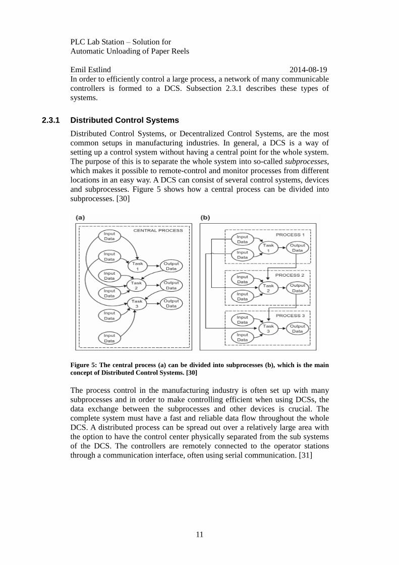
2.3.1 Distributed Control Systems
Distributed Control Systems, or Decentralized Control Systems, are the most
common setups in manufacturing industries. In general, a DCS is a way of
setting up a control system without having a central point for the whole system.
The purpose of this is to separate the whole system into so-called subprocesses,
which makes it possible to remote-control and monitor processes from different
locations in an easy way. A DCS can consist of several control systems, devices
and subprocesses. Figure 5 shows how a central process can be divided into
subprocesses. [30]
Figure 5: The central process (a) can be divided into subprocesses (b), which is the main
concept of Distributed Control Systems. [30]
The process control in the manufacturing industry is often set up with many
subprocesses and in order to make controlling efficient when using DCSs, the
data exchange between the subprocesses and other devices is crucial. The
complete system must have a fast and reliable data flow throughout the whole
DCS. A distributed process can be spread out over a relatively large area with
the option to have the control center physically separated from the sub systems
of the DCS. The controllers are remotely connected to the operator stations
through a communication interface, often using serial communication. [31]

PLC Lab Station – Solution for
Automatic Unloading of Paper Reels
Emil Estlind 2014-08-19
12
2.4 Current solutions for automatic unloading of paper reels
This section presents general information on systems currently used for
automatic unloading of paper reels in paper and pulp industries. Two different
systems will be considered, where the main focus is to evaluate these systems
based on the following criteria:
1. Functionality
2. Universality
3. Unloading time and reel weight
4. Control system
Subsection 2.4.1 presents a solution from Trancel Systems and a solution
provided by Joloda International is described in subsection 2.4.2.
2.4.1 Trancel Systems
The LOADMATE® [32] is an unloading solution provided by Trancel Systems,
designed for manufacturing and distribution industries. The main concept is
based on using a conveyor belt and steel channels in the trailer to push the
paper reels onto a docked loading truck, which can be seen in Figure 6. [32]
Figure 6: Trancel Systems automatic unloading. Standing reels are pushed onto the trailer
with conveyor belts. [32]
The paper and pulp industry SCA Ortviken [33] in Sundsvall, Sweden, have
recently installed an unloading solution from Trancel Systems. An interview
with an employee at SCA Ortviken has, based on the criteria in subsection 2.4,
given the following information regarding the system setup:

PLC Lab Station – Solution for
Automatic Unloading of Paper Reels
Emil Estlind 2014-08-19
13
1. The functionality of the solution is to unload standing paper reels to the
trailers, using rails placed in steel channels. The reels must be placed in
line on the rails before they are all simultaneously pushed into the
trailer. The standing reels are mostly not stacked when loaded even
though multiple stacking is a possibility, depending on the sizes of the
reels. Lying reels are transported to the unloading station using
conveyor belts and due to the fact that the reels are loaded standing up, a
cradle is designed to lift the reels to a standing position. [8]
2. Each trailer being loaded with the Trancel System needs to be provided
with steel channels and rails in the floor. In order to have a safe loading
and no movement of the trailer, a docking station is also necessary. [8]
3. The unloading time depends on factors like trailer length, maximum
speed on motors and the weight of the reels. A 13.6 meter semi-trailer
can load in less than three minutes. This only includes the loading itself
and therefore excludes the extra time spent redirecting the reels for the
unloading phase. The system is designed for smaller paper reels with a
weight of up to 1 000 kg. [8]
4. The control system setup is a Distributed Control System designed by
Siemens. The system has a total of three SIMATIC S7 PLCs, including
subprocesses for redirection, transportation and unloading. All PLCs are
programmed using SIMATIC STEP 7 Engineering Software and the
communication between the devices is established using PROFINET, a
networking standard based on TCP/IP and Ethernet. [8]
2.4.2 Joloda International
Joloda International is a market leading company for loading systems, mainly in
the UK, Europe and America. The company provides solutions for both manual
and automated loading systems. Joloda Internationals automated solution for
unloading of lying paper reels can be seen in Figure 7. [34]

PLC Lab Station – Solution for
Automatic Unloading of Paper Reels
Emil Estlind 2014-08-19
14
Figure 7: Joloda Internationals automatic unloading. Lying reels are pushed into the
trailer by conveyor belts. [34]
The main concept of this system is using a conveyor belt and steel channels in
the trailer to push the paper reels into a docked loading truck. The solution was
developed to transport large paper reels with a length and weight up to 1 873
mm and 2 200 kg respectively. [34]
1. The functionality of the solutions is to use four lanes of skates that move
in four channels placed in the trailer floor. When loading and unloading,
the lanes are raised using an airbag. This system is mainly designed for
the unloading of large lying paper reels. [34]
2. Each trailer being loaded with Joloda International system needs to be
provided with steel channels and rails in the floor. In order to have a
safe loading and no movement of the trailer, a docking station is also
provided. The solution requires manual involvement using fork lifts.
[34]
3. The unloading time depends on factors like trailer length and maximum
speed of motors. This solution loads 12 reels per trailer with a reel
weight of 2 200 kg. [34]
4. Further information regarding the control system setup could not be
presented since contact could not be established with the company.

PLC Lab Station – Solution for
Automatic Unloading of Paper Reels
Emil Estlind 2014-08-19
15
3 Methodology Chapter 3 presents the methodology used for the completion of the project. A
description of the literature study of the project is presented in subsection 3.1,
followed by the solution approach in subsection 3.2. Finally, in subsection 3.3,
an evaluation of the project as a whole is presented.
3.1 Literature study
Initially, a literature study will be mandatory in order to find the facts necessary
for the project. The study will be divided into two main areas of interest,
namely:
General understanding of PLCs and control systems
Currently used solutions for automatic unloading of paper reels
The main sources of the literature study are books and articles from the library
of Mid Sweden University [35]. Additional information regarding control
systems and current solutions for automatic unloading are gathered from
producers and an interview with an employee at the paper and pulp factory SCA
Ortviken in Sundsvall, Sweden.
3.2 Solution approach
The information gathered from the literature study will, together with the
demands from ÅF Consult, constitute the basis for the completion of the
project. The solution of the project is structured and executed as follows:
1. Design lab station
2. Develop station
3. Provide ÅF Consult with a test program
4. Simulate the emulation of the automatic solution for unloading of paper
reels.
Schematics are drawn and tests for the equipment are provided before the
development of the station. In order to test the equipment and present the
possibilities of the station to ÅF Consult, test programs will be written with
SIMATIC STEP 7 Engineering Software.
3.3 Evaluation
The project as a whole will be evaluated at the final stage of the project and it
will be based on the problem formulations and goals described in subsection
1.4. The lab station is evaluated in regards to functionality and possibilities. The
unloading solution will mostly be discussed but also simulated as an emulation
at the lab station.
PLC Lab Station – Solution for
Automatic Unloading of Paper Reels
Emil Estlind 2014-08-19
16
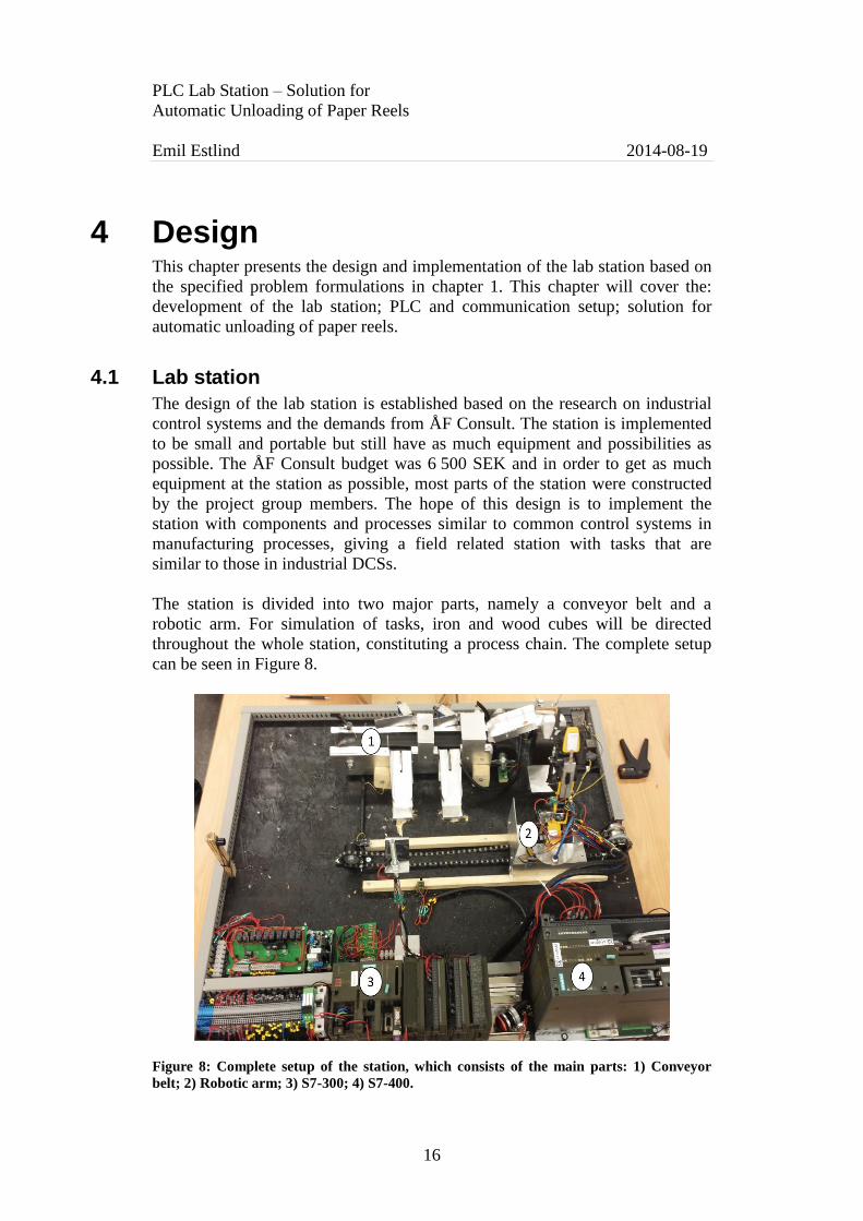
4 Design This chapter presents the design and implementation of the lab station based on
the specified problem formulations in chapter 1. This chapter will cover the:
development of the lab station; PLC and communication setup; solution for
automatic unloading of paper reels.
4.1 Lab station
The design of the lab station is established based on the research on industrial
control systems and the demands from ÅF Consult. The station is implemented
to be small and portable but still have as much equipment and possibilities as
possible. The ÅF Consult budget was 6 500 SEK and in order to get as much
equipment at the station as possible, most parts of the station were constructed
by the project group members. The hope of this design is to implement the
station with components and processes similar to common control systems in
manufacturing processes, giving a field related station with tasks that are
similar to those in industrial DCSs.
The station is divided into two major parts, namely a conveyor belt and a
robotic arm. For simulation of tasks, iron and wood cubes will be directed
throughout the whole station, constituting a process chain. The complete setup
can be seen in Figure 8.
Figure 8: Complete setup of the station, which consists of the main parts: 1) Conveyor
belt; 2) Robotic arm; 3) S7-300; 4) S7-400.

PLC Lab Station – Solution for
Automatic Unloading of Paper Reels
Emil Estlind 2014-08-19
17
4.1.1 Conveyor belt
The conveyor belt is one of the main parts of the station, designed for
transportation and sorting. The belt is designed to run in one direction and
consists of two sub parts, namely the storage and the belt. The complete setup
of the conveyor belt can be seen in Figure 9.
Figure 9: Complete setup of the conveyor belt, which consists of the main parts: 1)
Stockpile; 2) Load Cell; 3) Speed sensor; 4) Ramp 1; 5) Ramp 2; 6) Stockpile motor; 7)
Stockpile sensor; 8) Inductive sensor; 9) Photo diode; 10) Actuator 1; 11) Actuator 2. 12)
Emergency limit switch.
The storage is designed to contain multiple cubes (a maximum of four cubes). A
6 VDC motor pushes the cubes onto the belt via a ramp. A photo diode, placed
to sense the arm from the motor, works as a switch to see when a cube is pushed
onto the belt. An inductive sensor [36] is placed in the ramp to detect metal
cubes.
The conveyor belt was constructed by the project’s group members due to the
expenses of ready-made belts. Two 3D-printed rolls in plastic combined with
three fan belts and a motor, constitute the conveyor belt (see design of the rolls
in Figure 10). The functionality of the belt is to transport the cubes to the
robotic arm station and should be able to sort metal and wood cubes. Two
ramps are placed at the long side of the belt, directing cubes to the robotic arm
station. Each ramp has a limit switch, detecting if a cube is sliding down the
ramp. Two actuators are constructed with two 12 VDC solenoids, pushing out
metal walls to redirect the cubes as the conveyor belt is running. A photo cell is
placed at the start of the conveyor belt in order to detect both types of cubes. A
limit switch is placed at the end of the belt which serves as an emergency stop.
In addition, the conveyor belt is designed with speed regulation using a PWM
module [37]. In order to read the current speed of the belt, a photo resistive
sensor is placed under one of the 3D-printed rolls. Pieces of metal, placed at the
center of the roll, are designed to break the contact of the sensor resulting in an
impulse each time a metal piece passes. For further accuracy, four metal pieces
are used, resulting in a total of four impulses per revolution.

PLC Lab Station – Solution for
Automatic Unloading of Paper Reels
Emil Estlind 2014-08-19
18
Figure 10: Design of the 3D-printed rolls used in the construction of the conveyor belt.
4.1.2 Robotic arm
A 5-axis robotic arm is the main station of the setup, implemented as a pick-
and-place machine. Each axis movement of the arm is controlled by a 3 VDC
motor. The arm itself is placed on a trolley at the center of the station,
connected to a chain driven by a 6 VDC motor in order to move the arm
between the substations. Figure 11 shows the parts of the robotic arm, including
the motors.
Figure 11: The robotic arm consists of a rotational axis, bottom joint, middle joint, top
joint and a grip claw. These are controlled by the: rotation motor (1); bottom motor (2);
middle motor (3); top motor (4) and the grip claw motor (5). [38]

PLC Lab Station – Solution for
Automatic Unloading of Paper Reels
Emil Estlind 2014-08-19
19
The rotation of the arm is controlled by motor 1 and has, due to the wiring, a
positioning range of 180 degrees. Motor 2 controls the bottom joint of the arm
and is equipped with two limit switches for security reasons, giving a 90 degree
movement range from a vertical position to a nearly horizontal position. The
bottom joint is therefore mainly designed for two positions, i.e. at the extreme
positions.
Motor 3 also has a 90 degree movement range, using a resistive flex sensor [39]
to monitor the position. Motor 4 adjusts the top joint, with its position
monitored with another resistive flex sensor [39]. The top joint is designed to
move from a horizontal down to a nearly vertical position, due to the top
placement of the sensor. Motor 5 controls the grip claw, equipped with a
pressure sensor [40] in order to sense a gripped object as well as being able to
adjust the pressure based on the type of object.
In order for the six motors to run in both directions, a total of 12 relays are
connected between the S7-400 PLC and the robotic arm. Each motor is
connected to two relays according to Figure 12.
Figure 12: Control schematic for the motors of the robotic arm.
There are two implemented solutions for monitoring the position of the robotic
arm along the connected chain. An ultrasonic range sensor [41] is placed in line
with the arm to give the position of the trolley. The second solution is by using
limit switches and a photo diode. The limit switches are placed at the extreme
positions of the arm and the photo diode is placed in the middle of the chain.
The limit switches are designed as placement sensors for five of the stations
namely the: unloading station; the stockpile station; the weighing station; the
metal cube ramp; and the measuring station. The photo diode has the function
of a placement sensor for the second ramp. In order to monitor the placement of
the rotational axis of the arm, an inductive sensor is used together with four
metal pieces with 90 degree dislocation from each other. Using counters in the
PLC program results in an efficient way of monitoring the rotational position.

PLC Lab Station – Solution for
Automatic Unloading of Paper Reels
Emil Estlind 2014-08-19
20
4.1.3 Additional equipment
In addition to the equipment stated in subsections 4.1.1 and 4.1.2, the station is
also provided with the following equipment and functionality:
Scale: The station is provided with a load cell [43] in order to measure
small objects, up to 0.6 kg. Due to the low change of output voltage
from the load cell, a differential amplifier is designed to get the desired
value of 1-5 V to the PLC input. Figure 13 shows the amplifier setup for
the scale, using a MC3403PG [42] operational amplifier.
Figure 13: A load cell [43] used as a scale. An MC3403PG operational amplifier
is used as a differential amplifier in order to amplify the small output voltage
from the load cell.
Measuring station: The lab station is provided with a measuring station
for height and temperature measurements. This is not covered in this
thesis.
PC: In order to monitor and remote control the station, communication
to a PC is established via OPC with a server-client connection. This is
not covered in this thesis.
4.2 PLC setup
This section presents the setup in order to control the equipment of the lab
station. The control system is designed as a DCS using two PLCs in a master-
slave configuration. Due to the fact that ÅF Consults mainly work with
Siemens controllers, the station is limited to using a Siemens S7-400 series and
a S7-300 series PLC. Subsections 4.2.1 and 4.2.2 present the setup for the
Siemens S7-400 and the Siemens S7-300 respectively. In conclusion, subsection
4.2.3 presents the PROFIBUS configuration for the communication between the
nodes.

PLC Lab Station – Solution for
Automatic Unloading of Paper Reels
Emil Estlind 2014-08-19
21
4.2.1 Siemens S7-400
A Siemens S7 416-2 DP CPU [44] is used as the master device of the station,
equipped with: a power supply; a communication module for Ethernet; a digital
output card with 32 outputs. Included modules and the currently configured
addresses can be seen in Figure 14. The electrical schematics for the DO card
can be seen in Appendix B.
The S7-400 is mainly configured to control the six motors of the robotic arm
and to send and receive data to and from the S7-300 and a PC respectively.
Figure 14: Hardware configuration of the CPU 416-2 DP. In the rack the following is
included: the power supply (PS 407 10A) in slot 1; the CPU in slot 3-4; a communication
module for Ethernet connection in slot 5; a digital output card (32 outputs) in slot 6. The
addresses currently used are also shown.
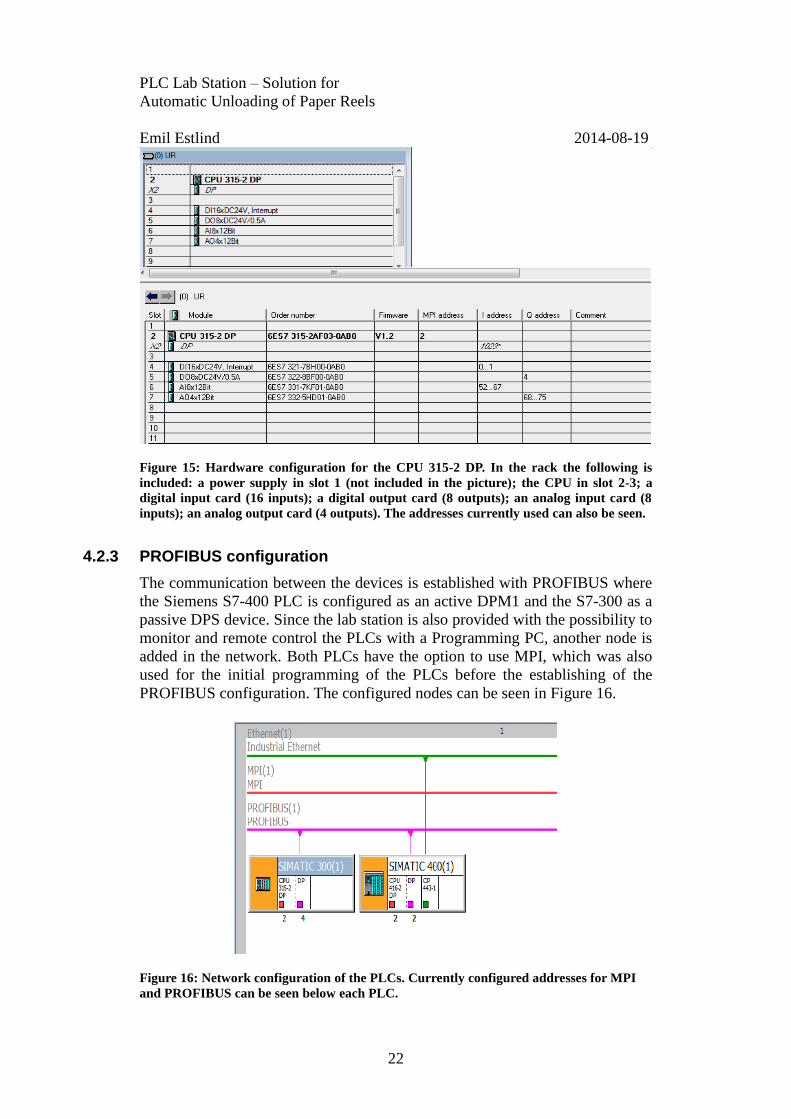
4.2.2 Siemens S7-300
A Siemens S7 315-2 DP CPU [45] is used as a slave device to the S7 416-2 DP
CPU. The CPU is equipped with: a power supply; a digital input card with 16
inputs; a digital output card with 8 outputs; an analog input card with 8 inputs;
an analog output card with 4 outputs. The modules and current addresses
included can be seen in Figure 15. The electrical schematics for the Siemens
S7-300 PLC can be seen in: Appendix C for DO; Appendix D for DI; Appendix
E for AO; Appendix F for AI.
The Siemens S7-300 PLC is mainly configured to control: the three actuators
on the conveyor belt; the conveyor belt motor; the rest of the equipment, i.e.
sensors and limit switches.
PLC Lab Station – Solution for
Automatic Unloading of Paper Reels
Emil Estlind 2014-08-19
22
Figure 15: Hardware configuration for the CPU 315-2 DP. In the rack the following is
included: a power supply in slot 1 (not included in the picture); the CPU in slot 2-3; a
digital input card (16 inputs); a digital output card (8 outputs); an analog input card (8
inputs); an analog output card (4 outputs). The addresses currently used can also be seen.
4.2.3 PROFIBUS configuration
The communication between the devices is established with PROFIBUS where
the Siemens S7-400 PLC is configured as an active DPM1 and the S7-300 as a
passive DPS device. Since the lab station is also provided with the possibility to
monitor and remote control the PLCs with a Programming PC, another node is
added in the network. Both PLCs have the option to use MPI, which was also
used for the initial programming of the PLCs before the establishing of the
PROFIBUS configuration. The configured nodes can be seen in Figure 16.
Figure 16: Network configuration of the PLCs. Currently configured addresses for MPI
and PROFIBUS can be seen below each PLC.

PLC Lab Station – Solution for
Automatic Unloading of Paper Reels
Emil Estlind 2014-08-19
23
The available I/O-addresses of the PLCs can be configured as inputs and
outputs between the nodes in the PROFIBUS connection. In order to have a
data flow between the master and the slave CPU, each PLC was configured
with the addresses seen in Figure 17. These addresses are pre-allocated for the
established communication. The PC used for monitoring and remote control is
directly connected to the Siemens S7-400 Ethernet connection board.
Figure 17: Address configuration between the PROFIBUS nodes, i.e. the S7-300 (slave)
and S7-400 (master).
4.3 Automatic unloading using a robotic arm
This section presents the solution of using a robotic arm for an automated
unloading of paper reels in the pulp and paper industry. The solution will only
be presented theoretically, where the advantages of the solution are the main
topic to consider. This solution will be further evaluated and discussed in
chapter 6.
Functionality
The main concept of the solution is to unload the paper reels to trailers using a
PLC controlled robotic arm. Loading will be carried out at the long side of
curtain side trailers. The arm should move on reels along one side of the trailer,
unless a system is installed on each side for faster unloading. Therefore, the arm
needs to be long enough to reach the far side of the trailer along the whole
trailer height for multiple stacking of reels. A standard semi-trailer has an inside
width of 2.54 meters [46].
In order to design a solution for different sizes of reels, a heavy duty robotic
arm is necessary. KUKA Robotics KR 1000 1300 TITAN PA [47] is a 6-axis
arm and is currently the strongest on the market, with a maximum payload of
1 300 kg. The maximum reach of the arm is 3 203 mm. The standard version of
this arm does not provide the top module for handling of the cylindrical reels.
Therefore, a top module with functionality as a grip claw is necessary. [47]
Universality
The main purpose of this solution is to design a universal unloading station,
discarding extra processes like redirection of reels and pre-installed equipment
in the trailers. The hope is to implement a solution that is completely automated
and able to unload to any trailer. This solution will only consider unloading to
and not from trailers, even though unloading from trailers would be based on
the same concept.

PLC Lab Station – Solution for
Automatic Unloading of Paper Reels
Emil Estlind 2014-08-19
24
Unloading time and reel weight
Due to the fact that this solution will not be implemented in real life, but instead
emulated as accurate as possible on the lab station, it is difficult to present times
for the unloading itself. This solution is expected to not have the capacity of
unloading as fast as currently used systems, but focus more on a completely
automated and reliable solution for different reel weights. The maximum
capacity of payload for the robotic arm will limit the weight handling to reels
under 1 300 kg.
Control system
Instead of using the KUKA Robotics provided controller, the control system
setup will be designed as a DCS using PLCs. The main concept of the setup is
to, in accordance with the setup at the lab station, use two PLCs to control
divided subprocesses. One PLC will mainly handle the movements of the arm
along the trailer and monitor the position of the arm. The other PLC will be
configured as master device and handle the motors of the robotic arm. Due to
the fact that this solution will not be implemented, it is difficult to pinpoint what
type of equipment the solution needs in terms of sensors, PLC modules and
further equipment.
4.3.1 Emulation to automatic solution on lab station
The solution presented in subsection 4.3 will be emulated at the lab station
using cubes instead of real paper reels. The hope is to test the DCS setup with a
test program designed according to the flow chart seen in Appendix A. The
following subprocesses are considered:
Stockpile station
Metal and wood cubes are stored in the stockpile until pushed out onto the
conveyor belt. The cubes are then sorted on the belt and, depending on the type
of cube, directed to either the weighing station (if metal) or the unloading
station (if wood). In case of an error or missing cubes, the program will loop
back to push out a new cube in the process chain.
Weighing station
The metal cubes from the conveyor belt are moved to the weighing station by
the robotic arm. This function is implemented to make sure that the objects for
unloading have the correct properties. If the weight is correct, the metal cube is
transported to the unloading station, otherwise it is moved back to the stockpile
again.
Unloading station
The unloading station is designed with the purpose to simulate unloading to a
curtain side trailer. The cubes are first placed in a line with a space of 1 cm
between each cube due to the width of the grip claw. Further on, as more cubes
are transported to the unloading station, multiple cubes are stacked on each
other.

PLC Lab Station – Solution for
Automatic Unloading of Paper Reels
Emil Estlind 2014-08-19
25
4.3.1.1 Software approach
The test program is written in SIMATIC STEP 7 Engineering Software, where
the complete setup is divided into one part for the S7-300 and one part for the
S7-400 PLC. Ladder Diagram was the language used for the programming.
Each PLC communicates with the operating system using an organization block
(OB1 default). The program is designed with function blocks that are called
from OB1 for execution. Each function block pertain a specific part of the lab
station in order to control each substation efficiently and provide an easy
readable program for further implementations and troubleshooting. The hope of
the program design is to easily configure the station for different purposes and
process flows. To divide the sub stations of the lab setup in function blocks
results in easy management of the robotic arm between the stations of the lab
setup. Implemented counters monitor how many cubes of each type the ramps
contain, which makes deciding the correct function call easy, whether the arm
should pick up a wood or metal cube. The count is calculated by using the limit
switches placed in the ramps.
Data flow between the peripherals and the PLCs are either analog or digital
values. The digital values are used as switches with the current state stored in
memory bits. The analog values are configured with different voltage levels
depending on type of sensor. The analog input values are configured as 1-10 V
range in the PLCs, i.e. the range for the values from the flex sensors, range
sensor, the grip claw pressure sensor and the load cell.
The analog values from the flex sensors
are handled in the PLCs with compare
blocks; see example code in Figure 18.
Input values from the sensors are
compared with pre-defined threshold
values for required positions of the joints
of the arm. The same applies to the range
sensor and the grip claw.
Figure 18: Compare block example.
Figure 19 shows an example of a
move block, which is used in
order to copy the analog values
from one memory area to
another. This data exchange is
established between peripherals
and the PLCs according to the
address configuration described
in subsection 4.2.3.
Figure 19: Move block example.

PLC Lab Station – Solution for
Automatic Unloading of Paper Reels
Emil Estlind 2014-08-19
26
5 Results This chapter presents the evaluation of the solutions in the work. The evaluation
is divided into main areas according to the stated problem formulations in
subsection 1.4. Subsection 5.1 presents the result of the design and construction
of the lab station, where the equipment and lab possibilities are covered.
Subsection 5.2 describes a lab task for the station. Subsection 5.3 presents the
results from the emulation of the automatic unloading. Finally, in subsection
5.4, existing solutions similar to the stated lab station will be presented.
5.1 Lab station
All equipment covered at the lab station is placed on a one square meter
plywood board, resulting in a portable solution. The hope of designing a field
related lab station is considered fulfilled since the equipment and the
development of the station is based on researched industrial solutions. The
proven usage of conveyor belts, sorting and pick-and-place functionality in
paper and pulp factories results in similar solutions being implemented at the
station. Together with the research provided from the other group members, the
final lab setup is implemented with equipment for industrial solutions regarding
transportation, measuring, monitoring and sorting processes.
The literature study showed that the extent of setups using DCSs are very
common for industrial solutions. One of the main purposes of designing the
station according to these types of systems resulted in configuring the PLCs to
control one subprocess each. The communication is established with a master-
slave configuration using PROFIBUS DP. The equipment of the lab station lack
accuracy due to a low budget, resulting in cheap and unreliable equipment. This
will be further discussed later on in this chapter.
5.1.1 Conveyor belt
The main functionalities of the conveyor belt are to sort and transport cubes.
Each substation of the belt is described separately in regards to the formed
problem statements.
The hope of designing a stockpile with the possibility to store multiple cubes
appeared to be a problem and was therefore redesigned. The demands of ÅF
Consults to have a small and portable station caused issues in regards to the
dimensions of the complete lab station. The height of the stockpile became a
problem and the solution was to place a ramp as a stockpile, making it possible
to store four cubes. Due to mechanical issues, the stockpile motor only pushes
correctly when only one cube is present in the stockpile; multiple cubes result
in a failure.

PLC Lab Station – Solution for
Automatic Unloading of Paper Reels
Emil Estlind 2014-08-19
27
The sorting on the conveyor belt has the possibility to sort two different types
of cubes, directing them to separate ramps. The two ramps from the conveyor
belt direct cubes correctly, but due to mechanical issues, the cubes are not
always placed at the correct spot for the robotic arm. Manual intervention is
necessary to remove cubes not correctly placed. The conveyor belt is designed
for speed control with correct functionality despite a smaller control range than
planned. This is because of the tension in the fan belts, resulting in a slower
speed than expected.
5.1.2 Robotic arm
The robotic arm is designed as a pick-and-place machine to transport the cubes
throughout the stations subparts. However, the arm is not considered as a
reliable solution due to the lack of accuracy of the required sensors. The
positioning along the board using the chain works correctly and the robotic arm
reaches all stations in an easy manner. The positioning of the arm is monitored
with either end position limit switches combined with a photo resistive diode or
using the provided range sensor. The range sensor has a dead zone of 30 cm and
its conical distribution result in a loss of focus as the arm moves towards the far
end of the chain. The low accuracy of the range sensor resulted in using the
other implemented solution as test programs and simulations were developed.
Sensors
The robotic arm is provided with a total of seven sensors to monitor the position
of its axes and rotations; see subsection 4.1.2 for implementation of these. The
hope of being able to control the arm with enough accuracy on all stations of
the lab setup is not fulfilled due to the low accuracy of the provided flex
sensors. The high movement of the arm results in high operation of the flex
sensors, which both tend to give different results each time they are used.
Measurements were done on each flex sensor twice before implementation. It
can be seen in Figure 20 and Figure 21 respectively, that the sensors are not
accurate due to differences between each trial. The output voltage is
proportional to the resistance but the fact that an offset occurs each time a
sensor is used results in a low accuracy of the arms position monitoring. The
placement of the grip claw is highly exposed and the arm’s tends to miss cubes
at stations, all depending on the behavior of the flex sensors.
The grip claw sensor has a steep resistance curve which results in difficulties
gripping with different pressures due to the mechanics of the grip claw.
However, the ability to grip with different pressures is available as the output
voltage changes in proportion to the pressure. The remaining implemented
sensors work as intended.

PLC Lab Station – Solution for
Automatic Unloading of Paper Reels
Emil Estlind 2014-08-19
28
Figure 20: Top flex sensor output signal to the Siemens S7-300 PLC, depending on the flex
angle. The angle range of the sensor is 0 to 45 degrees, starting from a horizontal position.
Figure 21: Middle flex sensor output signal to the Siemens S7-300 PLC, depending on the
flex angle. The angle range of the sensor is 0 to 90 degrees, starting from a vertical
position.

PLC Lab Station – Solution for
Automatic Unloading of Paper Reels
Emil Estlind 2014-08-19
29
5.1.3 Load cell
The load cell is designed to weigh the cubes and has a maximum load of 600 g.
The output from the load cell is a small voltage (microvolts) which required an
implementation of a differential amplifier. The amplifier was designed with a
gain of approximately 5 000 times. Since the resistance of the resistors are not
exactly the same result in a common-mode gain that differ from zero. A small
offset arise which can be seen in the equation in Figure 22. The input on the
PLC is set to 1-10 V which results in a loss of measuring range for the load cell.
As seen in Figure 22, the load cell can only measure objects with a weight of up
to 300 g due to configuration of a maximum of 10 V.
Figure 22: Output signal to the Siemens S7-300 PLC from the differential amplifier,
depending on the load.
5.2 Lab task
In order to introduce the functionality and equipment of the station, lab tasks
will be described. Lab tasks are covered in all three theses regarding this
project, with the main purpose to introduce employees and students to the lab
station designed. Tasks presented in this thesis can be seen in Appendix G.

PLC Lab Station – Solution for
Automatic Unloading of Paper Reels
Emil Estlind 2014-08-19
30
5.3 Emulation of unloading solution using robotic arm
An automatic solution for unloading of paper reels in paper and pulp industries
was presented in this thesis. The emulation showed that the cubes could be
unloaded according to the presented solution in subsection 4.3. Cubes were
unloaded to a station similar to how an unloading in a semi-trailer would work.
The unloaded cubes could be placed in a line and multiple stacking was
possible to a certain extent. The unreliability and accuracy of the equipment of
the station resulted in an unreliable unloading where stacking of cubes and the
distance between them varied depending on the behavior of the arm.
Using a DCS setup with two PLCs is a good approach for the solution designed.
This is confirmed by the result of the emulation as well as the fact that the
system currently used at SCA Ortviken is based on a similar setup using a
Siemens DCS with three Siemens S7 PLCs.
5.4 Similar lab station solutions
This subsection presents already existing solutions similar to the implemented
lab station considered in this thesis.
One of the main concepts of functionality for the station was to implement a
conveyor belt for transportation and sorting. An already existing solution from
Staudinger GMBH, namely the Compact Transport and Sorting Line, simulates
a sorting functionality for objects that are redirected to substations of the setup.
[48]
The station is equipped with the following components:
Sensors:
o 2 inductive proximity switches
o 7 mechanical switches
o 4 reed switches (magnetic switches)
Actuators:
o 1 motor with one direction
o 2 motors with two directions
o LED
Control System Requirements:
o 13 digital inputs
o 8 digital outputs
[48]
The Compact Transport and Sorting Line station can be seen in Figure 23.

PLC Lab Station – Solution for
Automatic Unloading of Paper Reels
Emil Estlind 2014-08-19
31
Figure 23: Compact Transport and Sorting Line from Staudinger GMBH. [48]
The robotic arm implemented at the station has the functionality of a pick-and-
place machine. A similar existing solution to this is the Compact High Level
Storage Warehouse from Staudinger GMBH, seen in Figure 24. The station
simulates a storage system with the possibility to sort and replace object with a
pick-and-place functionality. [49]
The station is equipped with the following components:
Sensors:
o 1 reed switch
o 16 mechanical switches
Actuators:
o 3 motors with two directions
o 2 LEDs
Control System Requirements:
o 15 digital inputs
o 8 digital outputs
[49]
Figure 24: Compact High Level Storage Warehouse from Staudinger GMBH. [49]

PLC Lab Station – Solution for
Automatic Unloading of Paper Reels
Emil Estlind 2014-08-19
32
6 Discussion This chapter presents the discussion of the solution and evaluation of the project
covered in the thesis. Subsection 6.1 presents the solution evaluation of the lab
station and the unloading solution. Subsection 6.2 presents ethical and social
aspects of the project and finally, future work is presented in subsection 6.3.
6.1 Evaluation of solution
The overall goals to design a lab station and emulate the automatic solution for
unloading of paper reels are fulfilled to some extent. The lab station was
implemented according to the planned design but it was difficult to get the
necessary accuracy of the equipment due to the low budget. One of the main
goals of the design of the station was to include as much equipment as possible
in order for the station to have many possibilities. A higher budget or the
removal of some equipment would have resulted in better accuracy of the parts
included. Due to problems during the construction of the station, which took
more time than expected, the time limits of 10 weeks resulted in less time to
research and to specify the solution for unloading of paper reels.
6.1.1 Lab station
The design and solution for the lab station and its related equipment are
discussed in this part, where problems and solution suggestions are presented.
The station could be implemented as a DCS setup on a small board, so the
solution provided is portable and field related according to the demands from
ÅF Consult. The goal of designing the station according to similar solutions in
industrial processes is fulfilled since it works well to use each PLC to control
the different stations of the setup.
Conveyor belt
The overall aim of the conveyor belt is reached even though some changes
would be appropriate in order to reach higher accuracy. A higher project budget
would have led to buying a ready-built conveyor belt which would have
removed the current problems due to mechanical issues. The fact that the
stockpile is unreliable for multiple cube handling removes one of the
functionalities with the belt itself, which could have been resolved with a
redesign or the usage of additional equipment.
Robotic arm
The robotic arm is the main station of the setup, which results in problem for
the entire construction due to the low accuracy. The two flex sensors are the
main issue since they both tend to give different results at each measurement.
This could have been resolved by using stepper motors in the arm for

PLC Lab Station – Solution for
Automatic Unloading of Paper Reels
Emil Estlind 2014-08-19
33
monitoring. The fact that the resistance ranges stated by the producers was 100
kΩ and turned out to be 40 kΩ and 4 kΩ respectively, results in a lower
resolution and therefore less accurate monitoring. The grip claw sensor could
also be improved with a different setup since the steep resistance curve of the
sensor and the mechanics of the grip claw result in problems gripping objects
using different pressures. Another issue with the positioning of the arm along
the board is the provided ultrasonic range sensor. As stated earlier, the sensor
tends to lose the focus of the arm as the distance from the sensor increases.
Using laser range sensors could be a good solution if further accuracy is
desired. The other solution (using limit switches and a photo diode) was
implemented in order to be able to move the arm to all stations designed. This
was possible due to the placement of the substations.
6.1.2 Unloading using robotic arm
The results of the research and development of the unloading solution are
discussed in this subsection. The problem formulations stated in subsection 1.4
are evaluated and discussed first. Advantages and motivation of the presented
solution are discussed.
How does currently used solutions for automatic unloading work?
Research of systems from Trancel Systems and Joloda International showed
that current solutions for automated unloading can be optimized. The following
criteria were considered and will be discussed:
1. Functionality
The existing solutions with conveyor belts tend to unload fast but in a
non-universal way. Rails and steel channels need to be provided as well
as docking stations. Manual intervention is also common.
2. Universality
Specific trailers are necessary for all unloading due to pre-installed
equipment. Demands to position paper reels correct in the unloading
station (either standing up or lying down) results in problems like extra
reel handling and not completely filled trailers. A half loaded trailer due
to non-stacking of reels cause problems in an environmental point of
view.
3. Unloading time and reel weight
An unloading time of approximately 3 minutes is fast and difficult to
improve further. However, the fact that reels have to be handled before
the unloading itself results in additional time. Paper reels are mainly
transported lying down in the factories, leading to additional handling of
reels before unloading.
4. Control system
The system at SCA Ortviken uses Siemens S7 PLCs in a DCS setup
with PROFINET connection.

PLC Lab Station – Solution for
Automatic Unloading of Paper Reels
Emil Estlind 2014-08-19
34
Is an automatic unloading solution using DCS setup with a PLC controlled
robotic arm possible?
Since the research showed that systems currently used have setups similar to the
lab station provided to ÅF Consult and due to additional research of equipment,
it has been proved that the solution would be appropriate in a control
engineering point of view. Mechanical aspects and complete equipment setup
for the solution are not considered. A DCS is a good choice for the solution to
separate the control of the arm itself from the movement and monitoring of the
system, which is confirmed as the designed setup at the lab station is
implemented similarly.
What equipment is necessary?
Due to the scope of the project and the time limit of the project, research
regarding equipment for the solution was not considered. However, since the
solution at SCA Ortviken is very similar to the solution presented in this thesis,
a good choice would be to use two S7 PLCs as a DCS setup with different
control purposes. Having the arm controlled by one PLC and controlling the
sensors and additional monitoring with another PLC would complete goals like:
simplicity of system; easy to troubleshoot; less cabling.
Will this solution result in a more efficient way of unloading in terms of:
functionality, universality, unloading time and heavy reel weight handling?
The solution would most likely not provide a faster unloading, even though the
unloading time could be halved if two systems were implemented on each side
of the unloading trailer. The functionality of the system itself would provide: a
completely automated solution; a universal solution with the possibility of
unloading to any trailer; less handling of reels. The solution would have the
possibility of handling reels weighing up to 1 300 kg. The fact that the robotic
arms constantly are improved results in the possibility for heavier reel handling
as heavy duty arms are redesigned.
Can the solution be simulated accurately at the lab station?
The solution could not be accurately simulated at the station due to the low
accuracy of the flex sensors. It is also debatable how good a simulation of a
system of this size could turn out at the implemented lab station. It is
impossible to see results like unloading time, reel handling and mechanical
solutions like the choice of equipment and safety precautions. However, the
solution gave positive results to the problem formulations in terms of validation
of the control setup. This, in combination with additional research of present
solutions and choices for robotic arms, proved that a system like this could be
implemented in a real situation after further research and designing.

PLC Lab Station – Solution for
Automatic Unloading of Paper Reels
Emil Estlind 2014-08-19
35
6.2 Ethical and social aspects
Since the project presented in this thesis concerns consultant work for ÅF
Consult, ethics have been considered towards the company as is stated in the
following paragraphs:
An honest and realistic approach has been considered when presenting
the lab station to ÅF Consult. The results have been presented honestly
in regards to functionality, where the problems and defects of the station
have been clearly stated.
Understanding of the provided technology and the functionality of the
equipment have been considered during the whole project to minimize
potential negative consequences. This mostly applies to the fact that the
equipment has been handled with caution and been tested before
implementation to minimize risks.
The equipment of the station is implemented with precautions in order
to eliminate the risk of breaking any part of the station. This is mainly
secured by having physical stops for the moving objects of the station,
i.e. the robotic arm and the conveyor belt. An emergency stop button is
installed on the setup in order to stop all subprocesses at the station if an
error occurs.
6.3 Future work
Suggestions for future work are shortly discussed in this subsection in regards
to the lab station in subsection 6.3.1 and the unloading solution in subsection
6.3.2.
6.3.1 Lab station
Even though the aim of the project has been reached, there are many areas to
work further on regarding the functionality of the station. There is always a
possibility to change the equipment for a more accurate system and the station
has some free space to facilitate the option. One of the goals of the project was
to implement control regulation, but it could not be achieved due to the time
limit. Further work would be to implement closed loop PID-control to the
conveyor belt in order to efficiently control different input flows of the cubes
directed on the belt. The speed regulation should be proportional to the input
flow. Further on, regulation could be added to the resistive flex sensors of the
robotic arm in order to get a more accurate positioning. The current
implementation tends to miss positions due to non-linear behavior of the
sensors. Implementation of PI- or PID-control could result in reaching a value
closer to the threshold.

PLC Lab Station – Solution for
Automatic Unloading of Paper Reels
Emil Estlind 2014-08-19
36
6.3.2 Unloading using robotic arm
The simulation of the unloading system showed that the control engineering
setup is a working solution, although the entire unloading system needs further
research and consideration. A good approach could be to: find out if the solution
provides more advantages to systems currently used; complete the design with
appropriate choices of equipment; implement the control system to the robotic
arm for tests. Another aspect to look deeper into is the fact that the arm would
handle heavy objects above the surface. Precautions needs to be considered for
safe handling of the reels and the mechanics of the system should be further
analyzed.

PLC Lab Station – Solution for
Automatic Unloading of Paper Reels
Emil Estlind 2014-08-19
37
References
[1] J. Norberg, “PLC Lab Station – Simulating an Automatic Quality
Control of Load Products”, Mid Sweden University, 2014.
[2] K. Andersson, “PLC Lab Station – An Implementation of External
Monitoring and Control Using OPC”, Mid Sweden University, 2014.
[3] PACE, “Evolution of Industrial Control Systems”,
http://www.pacetoday.com.au/features/evolution-of-industrial-control-
systems
Published 2013-12-04. Retrieved 2014-04-02.
[4] H. Jack, Automating manufacturing systems with PLCs, version 6.0,
2011, chapter 1.
https://sites.google.com/site/automatedmanufacturingsystems/Home/plc
s
[5] ÅF Consult, “Company Information”,
http://www.afconsult.com/en/About-us/Company-Information/
Retrieved 2014-04-02.
[6] Industrial Automation, “Why Automate?”,
http://www.industrialautomation.us/why_automate.php
Retrieved: 2014-08-01.
[7] Joloda, “Automatic Reel Unloading System”,
http://www.joloda.com/loading-systems/automatic-reel-unloading-
system
Retrieved: 2014-05-02.
[8] Bergström, Joel, [email protected] “Subject: Automatic
Unloading of paper reels” [email]. Personal email to Emil Estlind,
student, [email protected], 2014-07-10.
[9] Siemens, “SIMATIC S7-300”,
http://w3.siemens.com/mcms/programmable-logic-controller/en/simatic-
s7-controller/s7-300/Pages/Default.aspx
Retrieved: 2014-08-01.

PLC Lab Station – Solution for
Automatic Unloading of Paper Reels
Emil Estlind 2014-08-19
38
[10] Siemens, “SIMATIC S7-400”,
http://w3.siemens.com/mcms/programmable-logic-controller/en/simatic-
s7-controller/s7-400/Pages/Default.aspx
Retrieved: 2014-08-01.
[11] AMCI, “What is A Programmable Logic Controller (PLC)?”,
http://www.amci.com/tutorials/tutorials-what-is-programmable-logic-
controller.asp
Retrieved: 2014-08-01.
[12] H. Jack, Automating manufacturing systems with PLCs, version 6.0,
2011, chapter 1.
https://sites.google.com/site/automatedmanufacturingsystems/H
ome/plcs
[13] ISA, “IEC 61131-3 Industrial Control Programming Standard
Advancements”,
https://www.isa.org/standards-publications/isa-publications/intech-
magazine/2012/october/system-integration-iec-61131-3-industrial-
control-programming-standard-advancements/
Retrieved: 2014-08-01.
[14] IEC, “About the IEC”
http://www.iec.ch/about/?ref=menu
Retrieved: 2014-08-01.
[15] H. Jack, Automating manufacturing systems with PLCs, version 6.0,
2011, chapter 16.
https://sites.google.com/site/automatedmanufacturingsystems/H
ome/plcs
[16] Peng Zhang, Advanced industrial control technology, United Kingdom:
Elsevier Inc., 2010, s. 258-262.
[17] H. Jack, Automating manufacturing systems with PLCs, version 6.0,
2011, chapter 3. https://sites.google.com/site/automatedmanufacturingsystems/Home/har
dware
[18] Rexroth, “Understanding the IEC61131-3 Programming Languages”
http://www.automation.com/pdf_articles/IEC_Programming_Tha
yer_L.pdf Published: 2009. Retrieved: 2014-04-04.
PLC Lab Station – Solution for
Automatic Unloading of Paper Reels
Emil Estlind 2014-08-19
39
[19] R. Hyde, “The Art of Assembly Language”, 2nd edition, 2010.
https://courses.engr.illinois.edu/ece390/books/artofasm/artofasm.html
[20] The Learning Pit, “Instruction List Programming”,
http://www.thelearningpit.com/hj/plcs17.asp
Retrieved: 2014-08-01.
[21] H. Jack, Automating manufacturing systems with PLCs, version 6.0,
2011, chapter 8. http://engineeronadisk.com/V2/book_PLC/engineeronadisk-60.html
[22] E. Knapp, Industrial network security, USA: Elsevier Inc., 2011, s.55-
56.
[23] A. Bystricanova, A.Rybovic, “Data communication between
programmable logic controllers in the industrial distribution
applications”, Advances in Electrical and Electronic Engineering, vol.
9, nr. 2, 2011.
[24] D. Reynders, S.Mackay, E.Wright, Practical Industrial Data
Communications – Best Practice Techniques, Jordan Hill, GBR:
Butterworth-Heinemann, 2005, s.303-304.
[25] D. Reynders, S.Mackay, E.Wright, Practical Industrial Data
Communications – Best Practice Techniques, Jordan Hill, GBR:
Butterworth-Heinemann, 2005, s.314.
[26] K.L.S. Sharma, Overview of Industrial Process Automation, Saint Louis,
USA: Elsevier Inc., 2011, s.9.
[27] K.L.S. Sharma, Overview of Industrial Process Automation, Saint Louis,
USA: Elsevier Inc., 2011, s.6.
[28] K.L.S. Sharma, Overview of Industrial Process Automation, Saint Louis,
USA: Elsevier Inc., 2011, s.11.
[29] K.L.S. Sharma, Overview of Industrial Process Automation, Saint Louis,
USA: Elsevier Inc., 2011, s.153-155.
[30] Peng Zhang, Advanced industrial control technology, United Kingdom:
Elsevier Inc., 2010, s. 29.
[31] K.L.S. Sharma, Overview of Industrial Process Automation, Saint Louis,
USA: Elsevier Inc., 2011, s.156.

PLC Lab Station – Solution for
Automatic Unloading of Paper Reels
Emil Estlind 2014-08-19
40
[32] Trancel Systems, “Automatic Unloading”,
http://www.trancelsystems.se/products/automatic-loading/
Retrieved: 2014-05-01.
[33] SCA, “SCA Ortviken”,
http://www.sca.com/en/ppc/About-us/SCA-Publication-Papers/SCA-
Ortviken/
Retrieved: 2014-08-01.
[34] Joloda, “Automatic Reel Unloading System”,
http://www.joloda.com/loading-systems/automatic-reel-unloading-
system
Retrieved: 2014-05-02.
[35] Mid Sweden University, “Library and LRC”,
http://www.bib.miun.se/eng/
[36] IFM Efector Inc. 2010: NF5004 Inductive Sensor,
http://tds.ifm-electronic.com/tentacle/us/NF5004.pdf
[37] Velleman, 2003: DC to Pulse Width Modulator,
http://www.electrokit.com/productFile/download/257
[38] Elfa, “Robotic Arm kit, C-9895”,
https://www1.elfa.se/data1/wwwroot/assets/large/cebek-c-9895.jpg
Retrieved: 2014-07-10.
[39] Spectra Symbol: Flex Sensor FS,
http://www.electrokit.com/productFile/download/3181
[40] Interlink Electronics: FSR 408 Data Sheet – FSR 400 Series Square
Force Sensing Resistor,
http://www.electrokit.com/productFile/download/5025
[41] Maxbotix, 2012: HRLV-MaxSonar® - EZ™ L Series,
http://www.electrokit.com/productFile/download/3053
[42] ON Semiconductor, 2006: Single Supply Quad Operational Amplifier,
MC3403,
http://www.electrokit.com/productFile/download/960
[43] Zemic, 2013: Datasheet: L6B Load Cell,
https://www1.elfa.se/data1/wwwroot/assets/datasheets/L6B_Datasheet.p
df

PLC Lab Station – Solution for
Automatic Unloading of Paper Reels
Emil Estlind 2014-08-19
41
[44] Siemens, 2008: SIMATIC Automation Systems S7-400 CPU
Specifications.
https://support.automation.siemens.com/dnl/DM/DM0Mjg0OQAA_140
16796_HB/422rfhcpu_en.pdf
[45] Siemens, 2001: SIMATIC PLC S7-300 CPU Specifications.
http://www.automation.siemens.com/doconweb/pdf/SINUMERIK_SIN
AMICS_04_2010_E/S7300Re2.pdf?p=1
[46] YRC, “Semi-Trailer Dimensions”
http://www.yrc.com/shippers/semi-trailer-dimensions.html
Retrieved: 2014-07-01.
[47] KUKA Robotics, ”KR 1000 1300 TITAN PA”
http://www.kuka-
robotics.com/sweden/en/products/industrial_robots/special/palletizer_ro
bots/kr1000_1300_titan_pa/start.htm
Retrieved: 2014-04-15.
[48] Staudinger GMBH: Compact Transport and Sorting Line.
http://www.staudinger-est.de/en/simulation/compact-
models/documents/226004.pdf
Retrieved: 2014-08-12.
[49] Staudinger GMBH: Compact High Level Storage Warehouse.
http://www.staudinger-est.de/en/simulation/compact-
models/documents/226001.pdf
Retrieved: 2014-08-12.

PLC Lab Station – Solution for
Automatic Unloading of Paper Reels
Emil Estlind 2014-08-19
42
Appendix A: Test program Unloading of paper reels

PLC Lab Station – Solution for
Automatic Unloading of Paper Reels
Emil Estlind 2014-08-19
43
Appendix B: Siemens S7-400 Digital Outputs

PLC Lab Station – Solution for
Automatic Unloading of Paper Reels
Emil Estlind 2014-08-19
44
Appendix C: Siemens S7-300 Digital Outputs

PLC Lab Station – Solution for
Automatic Unloading of Paper Reels
Emil Estlind 2014-08-19
45
Appendix D: Siemens S7-300 Digital Inputs

PLC Lab Station – Solution for
Automatic Unloading of Paper Reels
Emil Estlind 2014-08-19
46
Appendix E: Siemens S7-300 Analog Outputs

PLC Lab Station – Solution for
Automatic Unloading of Paper Reels
Emil Estlind 2014-08-19
47
Appendix F: Siemens S7-300 Analog Inputs

PLC Lab Station – Solution for
Automatic Unloading of Paper Reels
Emil Estlind 2014-08-19
48
Appendix G: Lab tasks An introduction to lab station possibilities
These lab instructions are a basic introduction to the possibilities provided at
the station. All three theses regarding this project have lab tasks provided for
different implementations and this part will cover the setup of the PLCs and
PROFIBUS as well as introducing the conveyor belt station. Information and
tips can be obtained in this report.
1. Set up the hardware configuration for each PLC, which includes:
- Add all modules in the HW configuration
- Set appropriate addresses for each module
2. Set up the PROFIBUS configuration for the network.
- Set up the nodes in the network to DP1M(S7-400), DP2M(PC) and DPS
(S7-300)
- Configure the Siemens S7-400 PLC as master. Make sure that the digital
outputs are connected to the robotic arm.
- Configure the Siemens S7-300 PLC as slave. Make sure to check that
the inputs and outputs from the station are correct according to
provided schematics.
- Provide an address configuration for communication between each
node.
3. Write a program to configure the conveyor belt.
- Check that all related sensors and equipment function properly (make
sure to implement the stations emergency stop button and the
emergency limit switch at the end of the belt)
- Set a value on the memory word (MW) of the speed control in order to
have an appropriate speed. (Value between 6 000 and 20 000).
- Design the stockpile motor to push out a cube if one is present.
- Implement a sorting function where metal cubes are directed to the first
ramp and wood cubes to the second. The inductive sensor and the photo
cell are at your disposal.
4. Implement functionality for the two ramps.
- Stop the conveyor belt when a limit switch is pressed on either ramp.

PLC Lab Station – Solution for
Automatic Unloading of Paper Reels
Emil Estlind 2014-08-19
49
- Send values to the corresponding memory addresses in order for the
robotic arm to know whether a metal cube or wood cube should be
picked up.
5. Implement counters for monitoring of objects.
- Design counters that monitor how many metal and wood cubes that are
present at the conveyor belt station. Make sure to decrease the count if
the robotic arm picks up a cube from a ramp.