Embed Size (px)
Citation preview

1
INDAdeptG Technology for Deep
Desulfurization of Gasoline
by
S. Kumar
IndianOil R&D Centre Faridabad, India
Refining Challenges & Way Forward, April 16-17, 2012 at New Delhi

Overv
iew
Issues in producing ULSG
Options for Gasoline Desulph.
INDAdptG Process
Breakthrough Curve
SO2 Removal options
Present status
Summary

Minimum octane loss
Minimum yield loss
Minimum hydrogen consumption Capability to economically produce ULSG Conventional hydrotreating results in
saturation of total olefins and higher octane loss
Issue in producing ULSG

Achieve desulphurization with min. octane loss
Separate octane contributors (LCN) by fractionation
followed by HDS of remaining stream (HCN) - (Selective
HDS)
Compensate for the octane loss due to HDS by
isomerization of saturated hydrocarbons - (Non-selective
HDS)
Adsorption (physical/ reactive)
TECHNOLOGIES: PrimeG, OATS, SCANfining,
CDHydro, ISAL,OCTGAIN, S-Zorb, INDAdept
Options for Gasoline Desulphurization
5
INDAdept Process Features
Ideal for deep desulphurisation
of gasoline/ diesel
Proprietary adsorbent in
hydrogen environment
‘S’ removed by cleavage of
C-S bond followed by reactive
adsorption
Two reactors operated in swing
mode of adsorption and
regeneration
Adsorbent regenerated by
oxidation of ‘S’ to SO2 in
presence of lean air- nitrogen
mixture
Adsorption Regeneration
H2
Air
N2
Diesel
1 2

H 2
O 2
INDAdept Process

INDAdeptG Process
7
Ideal for S reduction from 1000 to < 10 ppm
RON reduction of 1-2 units
H2 consumption ~ 0.2 wt%
Suitable for treating Coker/ FCC gasoline
Employs single reaction step
Feed/Product Properties:

INDAdeptG Process Flow Diagram
Flash Drum
Reactor
Separator
Recycle Compressor
H2
Feed
Lt. Gases
Product
N2
N2 /H2
N2/O2
Water
Separator
Make-up H2
Make-up Caustic/ Amine
Activation
Combustion
Make-up Air
Recycle gas
H2 / HC Analyzers
Purging
Caustic
Separator
Separator
H2 / HC/ O2 Analyzers
Flare
CBD
Feed Storage
Fuel gas
Depressurization
Water wash
column
Scrubber/SRU
O2/CO2/CO Analyzers
Make-up
Water
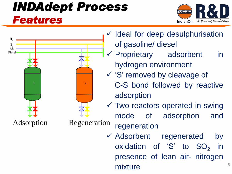
INDAdeptG Process Regeneration Flow Diagram

10
INDAdeptG Process Regeneration Cycle
Automatic Reactor swing mechanism &
necessary safety interlocks
Oxidation & activation steps conducted with
compositions below lower inflammability limit.
Further purging introduced before these steps
Typical Regeneration Cycle (4-8 days, Temp :
400 – 500 0C)

Depressurization
INDAdeptG Process Reactor swing operation
N2
N2 /H2
N2/O2 Activation
Combustion
Purging
H2 / HC/ O2 Analyzers
HC/H2/ O2 Analyzers Feed/ H2
HC/H2/ O2Analyzers
Adsorption

0
10
20
30
40
50
60
70
80
0 20 40 60 80 100 120 140 160 180 200
S (p
pm
)
Time on Stream (Hrs)
Gasoline Desulphurization
Feed = 60% Coker Gasoline + 40% FCC Gasoline
Feed 'S' = 1080 ppm
Feed Olefins = 26.5 wt%
Breakthrough Curve for
Gasoline Desulfurization
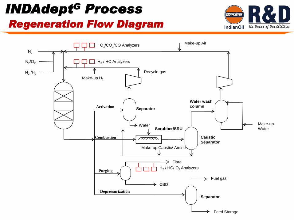
13
SO2 Containg gas stream from INDAdept
Caustic Scrubber
Integration with SRU
SO2 Removal/ Disposal Options

INDAdept Process Present Status
14
Process developed after Extensive pilot plant data
generated during last 7 years
Scale-up & Commercialization along with Design & Engg.
Consultant (EIL )
Adsorbent scale up & commercialization with Catalyst
Manufacturer (Sud-Chemie India Ltd.)
Demonstration unit of 35 TMTPA is under consideration in
one of IOC’s Refineries for reduction of sulfur content in
Heavy FCC gasoline from 1000 to 10 ppm

Summary
15
Lower consumption of H2 (0.12 -0.25 % of feed) in
INDAdeptG
Process can be used by refineries to meet EURO-
IV and EURO-V specifications
Lower Plant & Machinery cost
Lower octane loss

16