Embed Size (px)
Citation preview

BNL-112748-2016-JA
Jue Hu, Lijun Wu, Kurian A. Kuttiyiel, Kenneth R. Goodman, Chengxu Zhang, Yimei Zhu,
Miomir B. Vukmirovic, Michael G. White, Kotaro Sasaki, Radoslav R. Adzic
Submitted to Journal of the American Chemical Society
July 2016
Chemistry Department
Brookhaven National Laboratory
U.S. Department of Energy USDOE Office of Science (SC),
Basic Energy Sciences (BES) (SC-22)
Notice: This manuscript has been authored by employees of Brookhaven Science Associates, LLC under Contract No. DE- SC0012704 with the U.S. Department of Energy. The publisher by accepting the manuscript for publication acknowledges that the United States Government retains a non-exclusive, paid-up, irrevocable, world-wide license to publish or reproduce the published form of this manuscript, or allow others to do so, for United States Government purposes.
Increasing Stability and Activity of Core-Shell Catalysts by Preferential Segregation of
Oxide on Edges and Vertexes: Oxygen Reduction on Ti-Au@Pt/C

DISCLAIMER
This report was prepared as an account of work sponsored by an agency of the United States Government. Neither the United States Government nor any agency thereof, nor any of their employees, nor any of their contractors, subcontractors, or their employees, makes any warranty, express or implied, or assumes any legal liability or responsibility for the accuracy, completeness, or any third party’s use or the results of such use of any information, apparatus, product, or process disclosed, or represents that its use would not infringe privately owned rights. Reference herein to any specific commercial product, process, or service by trade name, trademark, manufacturer, or otherwise, does not necessarily constitute or imply its endorsement, recommendation, or favoring by the United States Government or any agency thereof or its contractors or subcontractors. The views and opinions of authors expressed herein do not necessarily state or reflect those of the United States Government or any agency thereof.

Increasing Stability and Activity of Core-shell Catalysts by Preferen-tial Segregation of Oxide on Edges and Vertexes: Oxygen Reduction on Ti-Au@Pt/C
Jue Hu,†,‡ Lijun Wu,§ Kurian A. Kuttiyiel,† Kenneth R. Goodman,‖ Chengxu Zhang, *,‡ Yimei Zhu,§ Miomir B. Vukmirovic,† Michael G. White,†,§ Kotaro Sasaki,† Radoslav R. Adzic*,†
†Chemistry Department, Brookhaven National Laboratory, Upton, NY 11973, USA ‡Institute of Plasma Physics, Chinese Academy of Sciences, P. O. Box 1126, 230031, China §Department of Condensed Matter Physics and Materials Science, Brookhaven National Laboratory, Upton, NY11973, USA ‖Department of Chemistry, Stony Brook University, Stony Brook, NY 11794, USA
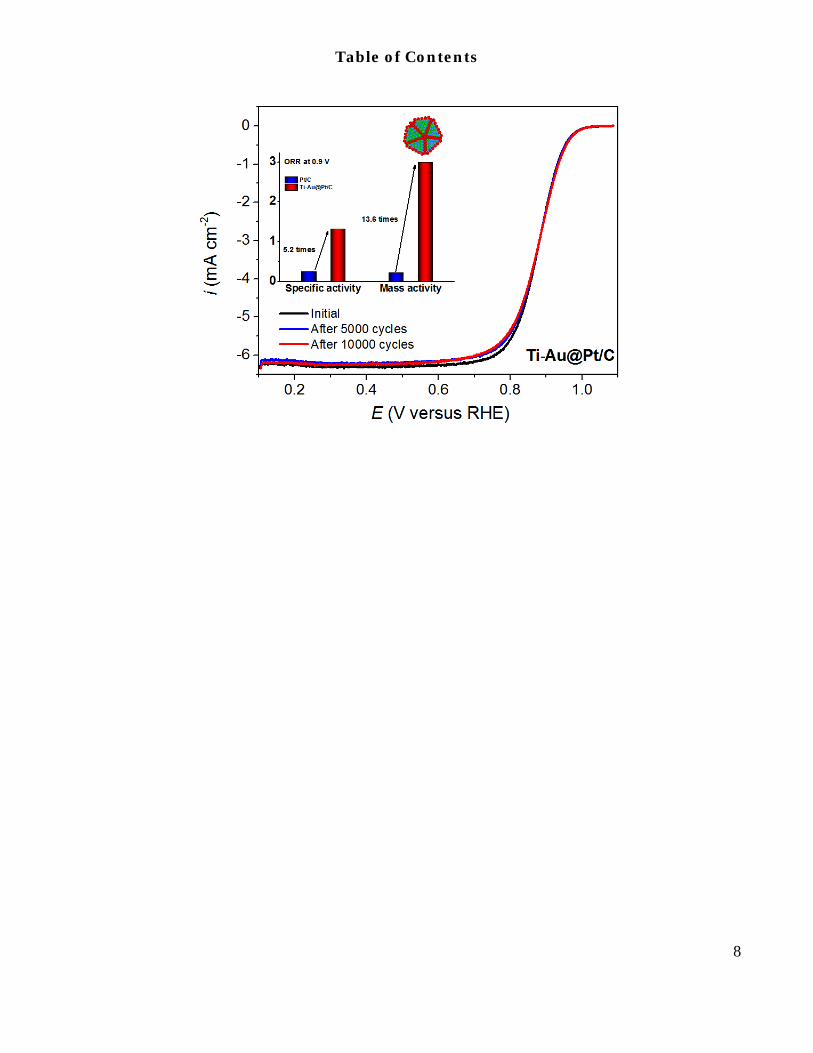
ABSTRACT: We describe a new class of core-shell nanoparticle catalysts having edges and vertexes covered by refrac-tory metal oxide that preferentially segregates onto these catalyst sites. The monolayer shell is deposited on the oxide-free core atoms. The oxide on edges and vertexes induces high catalyst’s stability and activity. The catalyst and synthesis are exemplified by fabrication of Au nanoparticles doped by Ti atoms that segregate as oxide onto low–coordination sites of edges and vertexes. Pt monolayer shell deposited on Au sites has the mass and specific activities for the oxygen reduction reaction about 13 and 5 times higher than those of commercial Pt/C catalysts. The durability tests show no activity loss after 10000 potential cycles from 0.6 to 1.0V. The superior activity and durability of the Ti-Au@Pt catalyst originate from protective Ti oxide located at the most dissolution-prone edge and vertex sites, and Au-supported active and stable Pt shell.
INTRODUCTION The slow kinetics of the oxygen reduction reaction
(ORR) is one of the key obstacles for the widespread commercialization of polymer electrolyte membrane fuel cells (PEMFCs), which has been established as one of the zero-emission power sources for the future.1-4 Platinum (Pt) is the most efficient and preferred choice electrocat-alyst for the cathodic oxygen reduction.5-7 However, the high cost and low utilization efficiency of the state-of-the-art Pt catalyst are the main obstacles for its broad application in PEMFCs. This can be resolved by the ORR catalysts having low Pt loading, high utilization efficien-cy, as well as high activity and durability. The intense research efforts have been focused on developing core-shell structure catalysts with Pt shell on transition metal cores.8-10 Great efforts have been devoted to synthesize the nano-segregated crystalline multimetallic nanoframes,5 and facet-controlled Pd nanocrystals.11 An-other noteworthy core-shell catalyst system is derived from de-alloying non-precious metal to obtain a Pt rich shell.9,12,13 Our group has been focusing on the design and synthesis of core-shell structure catalysts and have de-veloped a class of catalysts consisting of a Pt monolayer on different substrate metals and alloy, for example, Pd, Ru, Ir, Rh, PdAu, IrNi, IrRe, and AuNiFe.14-20 It appears that the degradation of transition metal cores in the core-shell catalysts is the major problem under harsh fuel-cell operation conditions.21 Our previous work also demonstrated that even Pd, a relatively stable transition
metal, undergoes certain dissolution from the cores in Pd@Pt core-shell catalysts.22
As a non-Pt group metal (non-PGM), Au is of consid-erable importance in electrochemical technology; given its possibility to improve stability of various catalysts and its several times larger natural abundance than that of Pt metals.23-25 The large scale application of Au will be un-likely to produce unpredictable fluctuation in supply and price due to its comparatively large holding and wide distribution in the world. According to the experimental study reported in our previous work, it has been proved that depositing Au cluster on Pt surface could suppress the degradations of Pt nanoparticles.24 Recently, Kodama and co-workers also demonstrated that Au as a vulnera-ble sites protector could improve the durability and ac-tivity of stepped Pt single-crystal.26 Thus, these observa-tions suggest a promising Au@Pt core-shell ORR catalyst with highly stable Au core and vulnerable sites protector which is generated by the spontaneously segregation of Au atoms onto the surface during electrochemical activa-tion due to the lower surface energy of Au than Pt.27 However, the lack of interest in the Au@Pt core-shell catalysts can be attributed to two impeding effects on ORR activity, that are, the strong bonding of OH and O to Pt due to the up-shifts of d-band center for Pt on Au core induced mainly by the strain effects, and the block-ing of active sites of Pt due to too much Au segregation onto the Pt surface.20,27,28 Here, we describe a novel Au@Pt core-shell catalyst with the low-coordinated sur-face sites doped by titanium oxide, e.g. vertex and edges,

2
while Pt occupies the surface facets. The as-prepared Ti-Au@Pt/C has a more effective hydrogenation of OHad on its Pt surface than commercial Pt/C catalyst, and exhibits a 5-fold enhancement of specific activity (1.32 mA cm–2) and 13-fold enhancement of mass activity (3.0 A mg–1) relative to the commercial Pt/C catalyst. Furthermore, in the Ti-Au@Pt/C catalysts, the highly active/distorted joint edges and corners are sealed by Ti-oxide that effec-tively prevent Au atoms from segregating onto the Pt surface and thus largely retained the electrochemical surface area (ECSA) and the ORR activity after potential cycling tests.
RESULTS In a typical synthesis of Ti doped Au (Ti-Au) nanopar-
ticles, Ti were first synthesized as the seeds by Super-Hydride reduction, followed by adding Au salt into the remaining mixture to reduce the Au salt to Au metal (see experimental section). The transmission electron mi-croscopy (TEM) and high-angle annular dark-field scan-ning TEM (HAADF-STEM) images reveal that the Ti-Au nanoparticles on the carbon substrate are highly dis-persed and have uniform size (the average size is about 6.8 nm). Most nanoparticles have polygonal shape with multiple facets (Figure S1). When the nanoparticles are viewed along <110> direction, five {111} twins are com-monly observed and likely have decahedral or icosahe-dral shape (Figure 1a and S2).
Figure 1a shows the high resolution TEM (HRTEM) image of a typical Ti-Au particle with truncated decahe-dral shape viewed along its five-fold axis ([110] direction in the fcc lattice). Five-fold {111} twins are also present in Figure S2 along with facets and edges. In order to obtain the distribution of Ti and Au, we performed electron en-ergy-loss spectroscopy (EELS) analysis. Figure 1d shows the EELS spectra from the edge and interior of the parti-cles after background subtraction, indicating uneven distribution of Ti and Au at the edge and interior of the particle. The line scan profile of the EELS signal intensi-ty using Au M54 and Ti L32 edges (Figure 1e) reveals the nanostructure of the Ti-Au nanoparticles with the Au in the core, while Ti decorated on the surface. 2D EELS signal intensity maps (Figure 1f-h and Figure S2) further reveals that Ti is mainly concentrated on the corners of the particles, indicating Ti is likely gathered at the joint edges and vertexes of the facets. DFT studies have demonstrated that Mo-oxides prefer to segregate onto the low-coordinated sites of the Pt catalyst surface, espe-cially at edge and vertex sites, which is reasonable be-cause metal-oxide normally has lower surface energy than the pure metal.7 In this study, the surface energy of Au (~1130 erg/cm2) is about 4 times larger than that of TiO2 (280-380 erg/cm2), suggesting a similar behavior o f T i - o x i d e l i k e M o - o x i d e w h i c h p r e f e r s
Figure 1. Microstructure of Ti doped Au nano-particles. a, High resolution TEM (HRTEM) image of a Ti-Au nanoparticle viewed along five-fold axis ([110] di-rection in fcc lattice), showing five twins and truncated decahedral shape (see supplemental materials for de-tails). b, Schematic of a partially truncated decahedral Ti-Au multiply twined nanoparticle with Au (green spheres) at core and Ti (red spheres) at the <110> edge of the facets. c, HAADF-STEM image, showing three nanoparticles. d, EELS of Ti L32 (top two lines) and Au M54 edges (bottom two lines) from area I (red) and area II (blue) marked by corresponding red and blue square in (c), indicating that there is Ti but little Au in area I, while Au but little Ti in area II. e, EELS signal intensity of Ti L32 (red triangles) and Au M54 (green circles) edges from the EELS spectrum image from the line scan indi-cated by the arrow in (a). The simultaneously acquired STEM-HAADF image intensity is drawn in solid black line. f, g, Signal intensity maps of (f) Ti L32 and (g) Au M54 edges from the 2D EELS spectrum image of the same particles, showing that Au is at core, while Ti dis-tributes at the surface of the particles, mainly at the sharp corners. h, Color mixture from (f) and (g). The simultaneously acquired STEM-HAADF image is shown in the inset. i, Au 4f and j, Ti 2p XPS spectra of Ti-Au/C sample.
to segregate onto the low-coordinated sites of Au sur-face.29 To further understand the nanostructure of Ti-Au
3
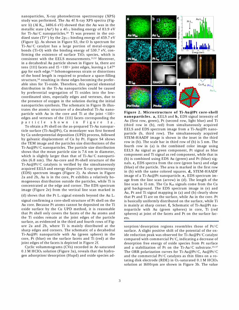
nanoparticles, X-ray photoelectron spectroscopy (XPS) study was performed. The Au 4f X-ray XPS spectra (Fig-ure 1i) (Al Kα, 1486.6 eV) showed that the Au was in the metallic state (Au0) by a 4f7/2 binding energy of 83.9 eV for Ti-Au/C nanoparticles.30 Ti was present in the oxi-dized state (Ti4+) by the 2p3/2 binding energy of 459.7 eV (Figure 1j). As shown in Figure S3, the O 1s spectrum for Ti-Au/C catalyst has a large portion of metal-oxygen bonds (Ti-O) with the binding energy of 530.7 eV, con-firming the existence of surface TiO2 species, which is consistent with the EELS measurements.31,32 Moreover, in a decahedral Au particle shown in Figure 1a, there are tens {111} facets and 15 <110> joint edges, leaving a 1.47° gap for each edge.33 Inhomogeneous strain or distortions of the bond length is required to produce a space-filling structure,34 resulting in these edges becoming the prefer-able sites for Ti-oxide. Therefore, this special elemental distribution in the Ti-Au nanoparticles could be caused by preferential segregation of Ti oxides into the low-coordinated sites, especially edges and vertexes, due to the presence of oxygen in the solution during the initial nanoparticles synthesis. The schematic in Figure 1b illus-trates the atomic structure of a decahedral Ti-Au nano-particle with Au in the core and Ti at the joint <110> edges and vertexes of the {111} facets corresponding the p a r t i c l e s h o w n i n F i g u r e 1 a .
To obtain a Pt shell on the as-prepared Ti-Au nanopar-ticle surface (Ti-Au@Pt), Cu monolayer was first formed by Cu underpotential deposition (UPD) process, followed by galvanic displacement of Cu by Pt. Figure S4 shows the TEM image and the particles size distributions of the Ti-Au@Pt/C nanoparticles. The particle size distribution shows that the mean particle size is 7.6 nm in diameter, which is slightly larger than that of Ti-Au/C nanoparti-cles (6.8 nm). The Au-core and Pt-shell structure of the Ti-Au@Pt/C catalysts is verified by the simultaneously acquired EELS and energy dispersive X-ray spectroscopy (EDS) spectrum images (Figure 2). As shown in Figure 2a and 2b, Au is in the core, Pt exhibits a relatively ho-mogeneous distribution outside the particles, while Ti is concentrated at the edge and corner. The EDS spectrum image (Figure 2e) from the vertical line scan marked in (d) shows that the Pt L∝ signal extends beyond the Au L∝ signal confirming a core-shell structure of Pt shell on the Au core. Because Pt atoms cannot be deposited on the Ti oxide surface by the Cu UPD method, it is reasonable that Pt shell only covers the facets of the Au atoms and the Ti oxides remain at the joint edges of the particle surface, as evidenced in the third and fourth rows of Fig-ure 2a and 2b, where Ti is mainly distributed at the sharp edges and corners. The schematic of a decahedral Ti-Au@Pt nanoparticle with Au (green sphere) in the core, Pt (blue) on the surface facets and Ti (red) at the joint edges of the facets is depicted in Figure 2f.
Cyclic voltammograms (CVs) recorded in Ar-saturated 0.1 M HClO4 solution (Figure 3a), reveals that the hydro-gen adsorption/desorption (Hupd) and oxide species ad-
Figure 2. Microstructure of Ti-Au@Pt core-shell nanoparticles. a, EELS and b, EDS signal intensity of Au (first row, green), Pt (second row, light blue) and Ti (third row in (b), red) from simultaneously acquired EELS and EDS spectrum image from a Ti-Au@Pt nano-particle (b, third row). The simultaneously acquired STEM-HAADF image is shown in the inset in the third row in (b). The scale bar in third row of (b) is 5 nm. The fourth row in (a) is the combined color image using EELS Au signal as green component, Pt signal as blue component and Ti signal as red component, while that in (b) is combined using EDS Au (green) and Pt (blue) sig-nals. c, EDS spectra from the core (green bars) and edge (blue) of the particle. The area is marked in the first row in (b) with the same colored squares. d, STEM-HAADF image of a Ti-Au@Pt nanoparticle. e, EDS spectrum im-age from the line scan (arrow) in (d). The length of the line scan is 15 nm. The Cu Kab signals come from the Cu grid background. The EDS spectrum image in (e) and Au, Pt and Ti signal mapping in (a) and (b) clearly show that Pt and Ti are on the surface, while Au in the core. Pt is basically uniformly distributed on the surface, while Ti is mainly at sharp corner. f, Schematic of Ti-Au@Pt na-noparticle with Au (green spheres) in core, Ti (red spheres) at joint of the facets and Pt on the surface fac-ets.
sorption/desorption regions resembles those of Pt/C surface. A slight positive shift of the potential of the ox-ide reduction peak was observed for Ti-Au@Pt/C catalyst compared with commercial Pt/C, indicating a decrease of desorption free energy of oxide species from Pt surface and a stabilization of Pt on the Ti-Au/C substrate.35-37 The ORR polarization curves for Ti-Au@Pt/C, Au@Pt/C and the commercial Pt/C catalysts as thin films on a ro-tating disk electrode (RDE) in O2-saturated 0.1 M HClO4 solution at 1600rpm are shown in Figure 3b. The value

4
Figure 3. Electrocatalytic properties of Ti-Au@Pt/C catalysts. a, Cyclic voltammograms of Ti-Au@Pt/C, Au@Pt/C and commercial Pt/C recorded in Ar-saturated 0.1 M HClO4 solution with a scan rate of 50 mV s–1 at room temperature. b, Corresponding ORR po-larization curves recorded in O2-saturated with a rotation rate of 1600 rpm and a scan rate of 10 mV s–1. Pt load-ings for Ti-Au@Pt/C, Au@Pt/C and commercial Pt/C catalysts were 1.1, 1.3 and 9.7 μg cm–2 respectively. c, Mass transport corrected Tafel plots based on specific current density for Au@Pt/C, Ti-Au@Pt/C and commer-cial Pt/C catalysts obtained from ORR polarization curves. d, Comparison of specific activities and mass activities at 0.9 V for Ti-Au@Pt/C and commercial Pt/C. Error bars show the variation of three sets of experi-mental repeats.
of diffusion current density indicates a complete reduc-tion of O2 to H2O (a four-electron process) on the surface of the Ti-Au@Pt/C catalyst.38,39 The half wave potential (E1/2) in the ORR polarization curve for Ti-Au@Pt/C core-shell catalyst which processes only one-ninth of the Pt loading of commercial Pt/C, is 25 mV higher than that of commercial Pt/C, indicating a much higher activity for Ti-Au@Pt/C core-shell catalyst.40 Since the half-wave potential is only indicator of ORR activity but not a true measure of it, Pt specific and mass activities at 0.9 V were calculated using the Koutecky-Levich equation and then normalized with respect to both the ECSA (ik,s) and the amount of Pt loading (ik,m). ECSA calculated by measuring the charge associated with the Hupd region between 0.05 to 0.35 V after double-layer charging cor-rection and assuming a value of 210 μC cm–2 for adsorp-tion of a hydrogen monolayer.7 As shown in Figure S6, both the specific activity and mass activity of the Ti-Au@Pt/C catalyst were clearly enhanced relative to the commercial Pt/C, verifying the accelerated ORR kinetics on the Ti-Au@Pt/C surface.41 Figure 3d compares the specific activity and mass activity for Ti-Au@Pt/C (1.32 mA cm–2 and 3.0 A mg–1) and commercial Pt/C (0.254 mA cm–2 and 0.22 A mg–1) catalysts at 0.9 V. The mass activity of the Ti-Au@Pt/C catalyst exhibits 13-fold en-hancement over commercial Pt/C catalyst, whereas the s p e c i f i c a c t i v i t y a c h i e v e s a 5 - f o l d
Figure 4. Electrochemical durability of the cata-lysts. a, ORR polarization curves and (inset) corre-sponding cyclic voltammgrams of Ti-Au@Pt/C catalyst before and after 10,000 potential cycles between 0.6 and 1.0 V. b, The losses of ECSAs (left) and mass activities (right) at 0.9 V of the Au@Pt/C, Ti-Au@Pt/C and the commercial Pt/C catalysts after 10,000 potential cycles between 0.6 and 1.0 V. c, High resolution TEM (HRTEM) image of a Ti-Au nanoparticle viewed along [110] direction, showing five twins and truncated deca-hedral shape. A decahedron is shown in the inset. The yellow arrows (the joint edges of the facets) are the vec-tors from the center apex to the bottom apexes. The scale bar is 5 nm. d, Magnified image from the area marked by white dash square in (c). e, Schematic diagram of a per-fect f.c.c. tetrahedral subunit viewed along [110] direc-tion.
improvement. Considering that Au is a non-platinum group metal, the PGM based mass activities for the Ti-Au@Pt/C and Au@Pt/C catalysts are equal to the Pt based mass activities. To get a deeper insight of this un-expected enhancement of the ORR activity on the dis-tinct Ti-oxide doped Pt surface, mass transport corrected Tafel plots based on specific current density (ik,s) for Ti-Au@Pt/C and Au@Pt/C were analyzed. As shown in Fig-ure 3c a low Tafel slope of -77 mV dec–1 was fitted for both the Ti-Au@Pt/C and Au@Pt/C catalysts at the high potential region from 0.95 V to 0.85 V, which is in close agreement with that of commercial Pt/C catalyst, indi-cating a similar ORR pathway with pure Pt surface at the high potential region. Typically, the Tafel plot on pure Pt surface in 0.1 M HClO4 solution was well fitted with two Tafel slopes: a lower Tafel slope at the high potential region and a higher Tafel slope at the low potential re-gion.42 It can be also clearly observed from Figure 3c that the Tafel slopes for both Au@Pt/C and commercial Pt/C c a t a l y s t s i n c r e a s e a t

5
Table 1. Comparison of electrochemical activity and durability of Au@Pt/C, Ti-Au@Pt/C and the commercial Pt/C catalysts.
the low potential region. The increase of Tafel slope at the low potential region was attributed to the sluggish ORR kinetics by the site blocking and electronic effects of adsorbed OHad on the Pt surface.42-44 OHad removal from Pt surface, which has been shown to be the rate-determining step of ORR for Pt-based catalysts, is crucial to improve the catalysts' performance.6,45,46 Damjanovic et al. attributed the two slopes to a change from a Tem-kin to a Langmuir ad- sorption conditions for reaction intermediates with decreasing coverage.47 At high cur-rent densities for Pt/C catalyst, coverage with oxygen is negligible and the kinetics under Langmuir conditions results in a high Tafel slope. At higher potentials, oxygen and coverage increases, the Temkin conditions become operative; the current density decreases which results in a low Tafel slope. Markovic et al. explained this behavior as being due to a change in the surface coverage of the chemisorbed oxygen-containing species that affect the adsorption of O2 on Pt.48 Based on these observations no change in the Tafel slope at high current density for the Ti doped Au@Pt catalyst seems to indicate that it is caused by the Temkin conditions created by the repulsive interaction of the Ti oxide species. DFT calculations has also demonstrated that the destabilization of OHad on Pt, which can be attributed to the repulsive interaction be-tween the OHad on Pt and the oxide species on a neigh-boring Ti,46 is responsible for enhancing the ORR kinet-ics, and at the same time possesses increased stability of Ti-Au@Pt/C catalyst under typical fuel cell operating condition.
In addition to the high electrochemical activities, the Ti-Au@Pt/C catalyst also exhibited excellent durability (Figure 4 and S7). The durability of the Ti-Au@Pt/C cat-alyst was evaluated using accelerated durability test
(ADT) by potential cycling between 0.6 and 1.0 V for 10,000 cycles in air-saturated 0.1 M HClO4 solution at a scan rate of 50 mV s–1. For comparison, the durability of Au@Pt/C and commercial Pt/C catalysts were also measured under the same conditions shown in Table 1 and Figure S8. As illustrated, after 10,000 cycles, the commercial Pt/C catalyst exhibited 8 mV shifts for its half-wave potential and 16% loss of its initial mass activi-ty due to the dissolution of Pt atoms and agglomeration of Pt nanoparticles through surface oxidation/reduction processes.5 On the other hand, during the potential cy-cling, the Ti-Au@Pt/C catalyst largely retained its activi-ty, exhibiting no loss for its half-wave potential. Fur-thermore, after 10,000 cycles, the mass activity of Ti-Au@Pt/C catalyst is still as high as 3.10 A mg–1. The mass activity and specific activity of the Ti-Au@Pt/C catalyst after 10,000 cycles exhibit a 13-fold and 5-fold enhancement over the initial performance of commercial Pt/C catalyst, respectively. The changes of ECSA and mass activity for Ti-Au@Pt/C, Au@Pt/C and commercial Pt/C catalysts were further examined by normalizing with respect to their initial ECSA and mass activity at 0.9 V, as shown in Figure 4b. It is worth noticing that Ti-Au@Pt/C catalyst retained its ECSA, while Au@Pt/C suffered the largest ECSA loss (31%) after 10,000 cycles among these three catalysts. Our previous study demon-strated that the movement of Au atoms from core to the defective sites gains high energy, resulting in that Au atoms preferentially residing on the surface low-coordinated sites (such as edge and vertex sites) by seg-regation process.28 The Au segregation process will mend the defective sites on the Pt surface inhibiting the disso-lution, and moreover, a little bit of Au on the Pt surface could further confer the catalyst durability by raising the
Catalyst Pt loading
(μg cm–2)
ECSA
(m2 g–1Pt)
E1/2
(mV)
Specific activity (mA cm–2)
at 0.9 V
Mass activity (A mgPGM–1)
at 0.9 V
Mass activity (A mgPt+Au–1)
at 0.9 V
Pt/C
Initial
9.7
86.6 853 0.254 0.22 0.22
After 10000 cycles 76.2 846 0.243 0.185 0.185
Au@Pt/C
Initial
1.3
194.7 845 0.63 1.21 0.08
After 10000 cycles 134.4 834 0.72 0.98 0.065
Ti-Au@Pt/C
Initial
1.1
225.4 878 1.32 3.00 0.35
After 5000 cycles 211.8 878 1.44 3.05 0.35
After 10000 cycles 203.2 878 1.53 3.10 0.36

6
Pt oxidation potential.24,49 However, too much of segre-gated Au atoms on the Pt surface will block the Pt active sites, resulting in a big loss of ECSA of the Au@Pt/C cat-alyst, and of course, a decrease of catalyst performance.
DISCUSSION Density functional theory (DFT) calculations indicate
that there is a stronger driving force for metal-oxide to segregate onto the catalyst surface relative to metal, and form metal-oxide species on the surface low-coordinated sites, especially on edge and vertex sites which are con-sidered to be the most stable surface sites for metal-oxide.7 The decahedral and icosahedral Au nanoparticles with {111} twins are commonly obtained by different syn-thesis methods.34,50,51 For a decahedral Au particle, there are tens {111} facets and 15 <110> joint edges. If the ver-texes are truncated, additional five (-112) and two (110) facets form, as shown in Figure 4c. The unit cell of the Au twin variant V1 and V2 are outlined by red and white rectangles, respectively. [110] projection of the Au atoms of the twin variants V1 and V2 are embedded in Figure 4d. Clearly, V2 is related with V1 by (1-11) reflection twin. Based on fcc (1-11) reflection twin relation, the angle be-tween the twin variants is 70.53°, five of them would take a total of 352.65°, leaving a 7.35°/5=1.47° gap for each edge, as shown in Figure 4e.33 Inhomogeneous strain or distortions of the bond length is required to produce a space-filling structure, as indicated by the red arrows.34,52 The distortion required for a decahedral particle with five-fold twins corresponds to a simple angular gap or wedge disclination, as shown in the dash circled area in Figure 4c. We think that these edges are the preferable sites for Ti-oxide, as confirmed by EELS composition map. The Pt then covers Au surface facets, e.g. {111} fac-ets. This core-shell structure would be more stable than that without Ti-oxide coating, because the highly ac-tive/distorted joint edges with gap are sealed by Ti-oxide for preventing Au from coming to the surface, thus im-proves the ORR durability. The much less ECSA loss for Ti-Au@Pt/C catalyst than that for Au@Pt/C catalyst af-ter 10000 cycles demonstrated the contribution of Ti-oxide to improved durability by preventing Au atoms from segregating onto the Pt surface. Moreover, due to the propensity for metal-oxide segregation on its ther-modynamically favored low-coordinated sites, Ti-oxide in the Ti-Au@Pt/C catalyst pinned at low-coordinated vertex and edge sites on the catalyst surface, inhibiting the dissolution of the catalyst.
CONCLUSION In summary, we described a promising new class of Pt
based catalysts having high activity and high durability for the ORR obtained by depositing Pt shell on Ti oxide doped Au core. EELS and XPS analyses proved the dis-tinct microstructure of Ti-Au@Pt nanoparticles with Au as the core, Pt as the shell and protective Ti oxide located in the highly active/distorted edge and vertex sites of the nanoparticles. The as-prepared Ti-Au@Pt/C catalyst possessed a more effective hydrogenation of OHad on its Pt surface than commercial Pt/C catalyst, and exhibits high ORR performance with a mass activity of 3.0 A mg–
1Pt and a specific activity of 1.32 mA cm–2 Pt, which are 13-
and 5-fold enhancements compared with commercial Pt/C catalyst. Furthermore, in the Ti-Au@Pt/C catalysts, Ti oxide doped on the Au@Pt surface effectively prevents Au atoms from segregating onto the Pt surface and thus can largely retain the ECSA and ORR activity of Ti-Au@Pt/C catalyst after 10,000 potential cycles.
ASSOCIATED CONTENT
Supporting Information The Supporting Information is available free of charge via the Internet at.
AUTHOR INFORMATION
Corresponding Author *[email protected]*[email protected]
Note The authors declare no competing financial interests.
ACKNOWLEDGMENT This manuscript has been authored by employees of Brookhaven Science Associates, LLC under Contract No. DE-SC0012704 with the U.S. Department of Energy. The publisher by accepting the manuscript for publication acknowledges that the United States Government retains a non-exclusive, paid-up, irrevocable, world-wide license to publish or reproduce the published form of this manuscript, or allow others to do so, for United States Government pur-poses. J.H. acknowledges the support by the National Na-ture Science Foundation of Anhui Province (No. 1508085QA10) and the Youth Innovation Promotion Asso-ciation of Chinese Academy of Sciences (No. 2015265).
REFERENCES (1) Gasteiger, H. A.; Marković, N. M. Science 2009, 324, 48. (2) Debe, M. K. Nature 2012, 486, 43. (3) Stamenkovic, V. R.; Fowler, B.; Mun, B. S.; Wang, G.; Ross, P.
N.; Lucas, C. A.; Marković, N. M. Science 2007, 315, 493. (4) Hernandez-Fernandez, P.; Masini, F.; McCarthy, D. N.;
Strebel, C. E.; Friebel, D.; Deiana, D.; Malacrida, P.; Nierhoff, A.; Bodin, A.; Wise, A. M.; Nielsen, J. H.; Hansen, T. W.; Nilsson, A.; StephensIfan, E. L.; Chorkendorff, I. Nat. Chem. 2014, 6, 732.
(5) Chen, C.; Kang, Y.; Huo, Z.; Zhu, Z.; Huang, W.; Xin, H. L.; Snyder, J. D.; Li, D.; Herron, J. A.; Mavrikakis, M.; Chi, M.; More, K. L.; Li, Y.; Markovic, N. M.; Somorjai, G. A.; Yang, P.; Stamenkovic, V. R. Science 2014, 343, 1339.
(6) Zhang, L.; Roling, L. T.; Wang, X.; Vara, M.; Chi, M.; Liu, J.; Choi, S.-I.; Park, J.; Herron, J. A.; Xie, Z.; Mavrikakis, M.; Xia, Y. Science 2015, 349, 412.
(7) Huang, X.; Zhao, Z.; Cao, L.; Chen, Y.; Zhu, E.; Lin, Z.; Li, M.; Yan, A.; Zettl, A.; Wang, Y. M.; Duan, X.; Mueller, T.; Huang, Y. Science 2015, 348, 1230.
(8) Wang, D. L.; Xin, H. L. L.; Hovden, R.; Wang, H. S.; Yu, Y. C.; Muller, D. A.; DiSalvo, F. J.; Abruna, H. D. Nat. Mater. 2013, 12, 81.
(9) Strasser, P.; Koh, S.; Anniyev, T.; Greeley, J.; More, K.; Yu, C. F.; Liu, Z. C.; Kaya, S.; Nordlund, D.; Ogasawara, H.; Toney, M. F.; Nilsson, A. Nat. Chem. 2010, 2, 454.
(10) Wang, D.; Xin, H. L.; Yu, Y.; Wang, H.; Rus, E.; Muller, D. A.; Abruña, H. D. J. Am. Chem. Soc. 2010, 132, 17664.
(11) Xie, S.; Choi, S.-I.; Lu, N.; Roling, L. T.; Herron, J. A.; Zhang, L.; Park, J.; Wang, J.; Kim, M. J.; Xie, Z.; Mavrikakis, M.; Xia, Y. Nano Lett. 2014, 14, 3570.
(12) Oezaslan, M.; Heggen, M.; Strasser, P. J. Am. Chem. Soc. 2012, 134, 514.

7
(13) Wu, Y.; Wang, D.; Niu, Z.; Chen, P.; Zhou, G.; Li, Y. Angew. Chem. Int. Ed. 2012, 51, 12524.
(14) Wang, J. X.; Inada, H.; Wu, L. J.; Zhu, Y. M.; Choi, Y. M.; Liu, P.; Zhou, W. P.; Adzic, R. R. J. Am. Chem. Soc. 2009, 131, 17298.
(15) Karan, H. I.; Sasaki, K.; Kuttiyiel, K.; Farberow, C. A.; Mavrikakis, M.; Adzic, R. R. Acs Catalysis 2012, 2, 817.
(16) Zhang, Y.; Hsieh, Y. C.; Volkov, V.; Su, D.; An, W.; Si, R.; Zhu, Y. M.; Liu, P.; Wang, J. X.; Adzic, R. R. Acs Catal. 2014, 4, 738.
(17) Zhang, Y.; Ma, C.; Zhu, Y. M.; Si, R.; Cai, Y.; Wang, J. X.; Adzic, R. R. Catal. Today 2013, 202, 50.
(18) Kuttiyiel, K. A.; Sasaki, K.; Choi, Y.; Su, D.; Liu, P.; Adzic, R. R. Energy Environ. Sci. 2012, 5, 5297.
(19) Hsieh, Y.-C.; Zhang, Y.; Su, D.; Volkov, V.; Si, R.; Wu, L.; Zhu, Y.; An, W.; Liu, P.; He, P.; Ye, S.; Adzic, R. R.; Wang, J. X. Nat. Commun. 2013, 4, 1.
(20) Zhang, J.; Vukmirovic, M. B.; Xu, Y.; Mavrikakis, M.; Adzic, R. R. Angew. Chem. Int. Ed. 2005, 44, 2132.
(21) Yang, H. Angew. Chem. Int. Ed. 2011, 50, 2674. (22) Sasaki, K.; Naohara, H.; Cai, Y.; Choi, Y. M.; Liu, P.;
Vukmirovic, M. B.; Wang, J. X.; Adzic, R. R. Angew. Chem. Int. Ed. 2010, 49, 8602.
(23) Corti, C.; Holliday, R.; Thompson, D. Gold Bull. 2002, 35, 111.
(24) Zhang, J.; Sasaki, K.; Sutter, E.; Adzic, R. R. Science 2007, 315, 220.
(25) Maroun, F.; Ozanam, F.; Magnussen, O. M.; Behm, R. J. Science 2001, 293, 1811.
(26) Kodama, K.; Jinnouchi, R.; Takahashi, N.; Murata, H.; Morimoto, Y. J. Am. Chem. Soc. 2016, 138, 4194.
(27) Ruban, A. V.; Skriver, H. L.; Nørskov, J. K. Phys. Rev. B 1999, 59, 15990.
(28) Sasaki, K.; Naohara, H.; Choi, Y. M.; Cai, Y.; Chen, W. F.; Liu, P.; Adzic, R. R. Nat Commun 2012, 3.
(29) Zhang, L.; Persaud, R.; Madey, T. E. Phys. Rev. B 1997, 56, 10549.
(30) Zhang, P.; Sham, T. K. Phys. Rev. Lett. 2003, 90, 245502. (31) Hu, J.; Jiang, L.; Zhang, C.; Zhang, X.; Meng, Y.; Wang, X.
Appl. Phys. Lett. 2014, 104, 151602. (32) Jianjin, D.; Jue, H.; Lin, X.; Yuanbin, W.; Chao, Z.; Yuedong,
M.; Chengxu, Z. Plasma Sci. Technol. 2015, 17, 303. (33) Johnson, C. L.; Snoeck, E.; Ezcurdia, M.; Rodriguez-
Gonzalez, B.; Pastoriza-Santos, I.; Liz-Marzan, L. M.; Hytch, M. J. Nat. Mater. 2008, 7, 120.
(34) Wang, Z. L. J. Phys. Chem. B 2000, 104, 1153. (35) Zhao, X.; Chen, S.; Fang, Z.; Ding, J.; Sang, W.; Wang, Y.;
Zhao, J.; Peng, Z.; Zeng, J. J. Am. Chem. Soc. 2015, 137, 2804. (36) Hu, J.; Kuttiyiel, K.; Sasaki, K.; Su, D.; Yang, T.-H.; Park, G.-
G.; Zhang, C.; Chen, G.; Adzic, R. Catalysts 2015, 5, 1321. (37) Van der Vliet, D. F.; Wang, C.; Li, D.; Paulikas, A. P.; Greeley,
J.; Rankin, R. B.; Strmcnik, D.; Tripkovic, D.; Markovic, N. M.; Stamenkovic, V. R. Angew. Chem. Int. Ed. 2012, 124, 3193.
(38) Wang, C.; Daimon, H.; Onodera, T.; Koda, T.; Sun, S. Angew. Chem. Int. Ed. 2008, 47, 3588.
(39) Niu, W.; Li, L.; Liu, X.; Wang, N.; Liu, J.; Zhou, W.; Tang, Z.; Chen, S. J. Am. Chem. Soc. 2015, 137, 5555.
(40) Kuttiyiel, K. A.; Sasaki, K.; Choi, Y. M.; Su, D.; Liu, P.; Adzic, R. R. Nano Lett. 2012, 12, 6266.
(41) Escudero-Escribano, M.; Verdaguer-Casadevall, A.; Malacrida, P.; Grønbjerg, U.; Knudsen, B. P.; Jepsen, A. K.; Rossmeisl, J.; Stephens, I. E. L.; Chorkendorff, I. J. Am. Chem. Soc. 2012, 134, 16476.
(42) Wang, J. X.; Markovic, N. M.; Adzic, R. R. J. Phys. Chem. B 2004, 108, 4127.
(43) Marković, N. M.; Gasteiger, H. A.; Grgur, B. N.; Ross, P. N. J. Electroanal. Chem. 1999, 467, 157.
(44) Wang, J. X.; Zhang, J.; Adzic, R. R. J. Phys. Chem. A 2007, 111, 12702.
(45) GreeleyJ; Stephens, I. E. L.; Bondarenko, A. S.; Johansson, T. P.; Hansen, H. A.; Jaramillo, T. F.; RossmeislJ; ChorkendorffI; Nørskov, J. K. Nat. Chem. 2009, 1, 552.
(46) Zhang, J.; Vukmirovic, M. B.; Sasaki, K.; Nilekar, A. U.; Mavrikakis, M.; Adzic, R. R. J. Am. Chem. Soc. 2005, 127, 12480.
(47) Damjanov.A; Genshaw, M. A. Electrochim Acta 1970, 15, 1281.
(48) Markovic, N. M.; Adzic, R. R.; Cahan, B. D.; Yeager, E. B. J Electroanal Chem 1994, 377, 249.
(49) Kuttiyiel, K. A.; Sasaki, K.; Su, D.; Vukmirovic, M. B.; Marinkovic, N. S.; Adzic, R. R. Electrochim. Acta 2013, 110, 267.
(50) Zheng, Y.; Tao, J.; Liu, H.; Zeng, J.; Yu, T.; Ma, Y.; Moran, C.; Wu, L.; Zhu, Y.; Liu, J.; Xia, Y. Small 2011, 7, 2307.
(51) Johnson, C. J.; Dujardin, E.; Davis, S. A.; Murphy, C. J.; Mann, S. J. Mater. Chem 2002, 12, 1765.
(52) Marks, L. D. Rep. Prog. Phys. 1994, 57, 603.
8
Table of Contents