Embed Size (px)
Citation preview

INDUSTRIAL SOLUTIONS 695
INTERNATIONAL DESIGN CONFERENCE - DESIGN 2002 Dubrovnik, May 14 - 17, 2002.
INCREASING LOAD CAPACITY OF SPLINES DUE TO DESIGN
Günter Schäfer and Martin Garzke
Keywords: shaft/hub-connection, design-options, manufacturing
1. Introduction The spline is a common element for shaft/hub-connections with high performance in torque transmission. Regarding to spline connections several national and international standards exist (e.g. ISO 4156, ANSI B92, DIN 5480, DIN 5466). These standards offer a lot of information about the main features and basic use of splines. For special applications referring to loads, dimensions, materials and manufacturing the designer has to use his freedom in splines micro-design to increase the load capacity above the ordinary limits. This paper shows some industrial applications of modified splines.
2. Design options
2.1 Root radius The variation of root radius and geometry (flat/fillet) can be used to reduce the stress concentration factor. A simple two dimensional consideration of the spline geometry leads to the requirement of a fillet root with maximum radius. The consequence is that the core area of the shaft is reduced, which caused a minor torque resistance. By means of examples will be shown how to balance this restrictions on a high level.
Figure 1. Profile of the basic rack for 30° flat root spline

696 INDUSTRIAL SOLUTIONS
Figure 2. Profile of the basic rack for 30° fillet root spline
2.2 Flank line The elasticity of the shaft and hub material caused different torque deformations in the two elements. The result is a different micro geometry which leads to an unbalanced load distribution with load peaks at one end of the spline. One way to improve the balance of the load distribution over the length is the amendment of flank line angle (helix). The calculation of this flank correction based on the elastic behaviour of the spline materials and geometry.
Figure 3. Cracked spline
INDUSTRIAL SOLUTIONS 697
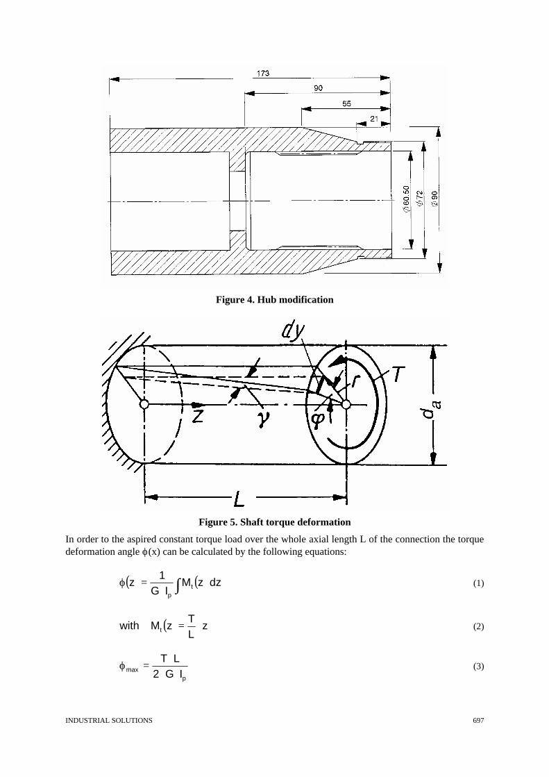
Figure 4. Hub modification
Figure 5. Shaft torque deformation
In order to the aspired constant torque load over the whole axial length L of the connection the torque deformation angle ϕ(x) can be calculated by the following equations:
( ) ( )∫⋅=ϕ dzzM
IG1
z tp
(1)
( ) zLT
zMwith t ⋅= (2)
pmax IG2
LT⋅⋅
⋅=ϕ (3)

698 INDUSTRIAL SOLUTIONS
This corrected flank geometry is easy to manufacture by plastic forming due to the GROB process. The advantage of this process is the inducted compression stress in the root area, especially in the run-out. The compression stress in combination with the sleek flank surface leads to higher fatigue resistance. A flank geometry correction is also useful for shaft-hub connections with the recommended ratio of length to diameter equal 0,6 or greater.
2.3 Centering The additional centering by a cylindrical surface for partial load transmission according to the principle „division of tasks“ grants an advanced radial force suitability. Radial forces often exist in practical applications, but they are the main reason for high friction wear which leads from a hidden to a direct damage. By the principle „division of tasks“ the designer is able to dedicated features to the different types of loads (torque, radial forces). In figure 6 the radial centering by doubletooth is shown. The number of doubleteeth can be up from 3. Another way of radial centering is the design of rings located at both axial ends of the connection. This is not so easy to manufacture as the doubletooth.
Figure 6. “Doubletoothed” shaft for centering
Problematical in use of such additional centering surfaces is the potential competition with the self centering behaviour of the spline. It may cause high internal loads if the center axis of both entities are not the same.
2.4 Pressure angle Another possibility to handle radial forces in such self-centering splines is the variation of the pressure angle from 20° up to 45° due to the combination of torque and radial load. The greater values yields to a higher capability for radial loads but in combination with greater tangential stresses in the hub. The designer has to decide what is the better solution for his application. Some industrial examples are interpreted to this facts to help the designer finding the right decision.

INDUSTRIAL SOLUTIONS 699
Figure 7. Profile of the basic rack for 45° fillet root spline
2.5 Run-out geometry The current research work at the Institut für Maschinenwesen on splines in co-operation with the industry are the design versions of run-out geometry at the end of the toothed length which is a critical area with high stress levels. Under this topic shall be discussed the design options related to the manufacturing resources.
Figure 8. Stress distribution at the run-out

700 INDUSTRIAL SOLUTIONS
3. Results The regular design and calculation of a spline has to be done according to the standards (e.g. DIN 5480, DIN 5466, ISO 4146). For complex applications in matters of geometry, load or material the designer can use his freedom in splines micro-design. The main stress concentration depends on the tooth root geometry. By changing from the flat to the fillet root this critical concentration will be decreased at 0,8. For uniformly distributed load on the flanks in axial direction it is necessary to use a geometry correction in reference to the elastic deformation behaviour of the spline. To reduce the friction wear it is a common feature to add circular surfaces to the tooth to transmitt the radial forces. The same goal is achievable by increasing the pressure angle if the hub is able to endure the additional load. Further possibilities are in the manufacturing process, e.g. the plastic forming. Using the visualised notions enables the designer to increase the load capability of a common spline connection above the ordinary limitations.
References Dietz, P.: Die Berechnung von Zahn- und Keilwellenverbindungen. Selbstverlag des Verfassers, Büttelborn 1978 Dietz, P.; Wesolowski, K.: Zahnwellenfestigkeit. Abschlußbericht zum DFG-Forschungsvorhaben Di 289/9-1. Institut für Maschinenwesen der TU Clausthal, 1994 Dietz, P; Schäfer, G.; Wesolowski, K.: Betriebsverhalten und Lebensdauer von Zahnwellen-Verbindungen. DVM-Tagung: "Maschinenelemente und Lebensdauer - Gestaltung und Optimierung", Dresden 1995, DVM-Bericht 121 Schäfer, G.: Der Einfluß von Oberflächenbehandlungen auf das Verschleißverhalten flankenzentrierter Zahn-wellen-Verbindungen mit Schiebesitz. Dissertation TU Clausthal 1995 Dietz, P.; Garzke, M.: Statische und dynamische Beanspruchbarkeit von Zahnwellen-Verbindungen unter elastischem und teilplastischem Werkstoffverhalten. Abschlußbericht zum DFG-Forschungsvorhaben Di 289/9-2. Institut für Maschinenwesen der TU Clausthal, 1998 Schäfer, G.: Gleichmässigkeit zur Leistungssteigerung. Institutsmitteilung Nr. 25, ISSN 0947-2247, IMW TU Clausthal 2000, pp 23-24 Dr.-Ing. Günter Schäfer Fritz-Süchting-Institut für Maschinenwesen Technische Universität Clausthal Robert-Koch-Str. 32, D-38678 Clausthal-Zellerfeld, Germany Phone: +49 5323/72-3894, Fax: +49 5323/72-3501 Email: [email protected]