Embed Size (px)
Citation preview
BRITISH STANDARD BS EN 12259-1:1999 Incorporating Amendments Nos. 1, 2 and 3 and Corrigendum No. 1
Fixed firefighting systems — Components for sprinkler and water spray systems —
Part 1: Sprinklers
The European Standard EN 12259-1:1999, with the incorporation of amendments A1:2001, A2:2004 and A3:2006, has the status of a British Standard
ICS 13.220.20
�������������� ���������������������������������������������������Copyright British Standards Institution Provided by IHS under license with BSI - Uncontrolled Copy Licensee=Hong Kong Polytechnic Univ/9976803100
Not for Resale, 05/14/2007 00:07:41 MDTNo reproduction or networking permitted without license from IHS
--`,`,`,,``,,`,```,,,``,``,,``-`-`,,`,,`,`,,`---
BS EN 12259-1:1999
This British Standard, having been prepared under the direction of the Health and Environment Sector Policy and Strategy Committee, was published under the authority of the Standards Policy and Strategy Committee on 15 September 1999
© BSI 2006
ISBN 0 580 32942 9
National foreword
This British Standard is the official English language version of EN 12259-1999, including amendments A1:2001, A2:2004 and A3:2006.
This European Standard is the subject to transitional arrangements agreed under a Commission mandate which is intended to lead to CE marking in support of the Construction Products Directive. In order to allow for any changes in national regulations, the Member States have agreed a transition period.
This period (date of applicability) started with an announcement in the Official Journal of the European Communities (OJ) on 1 April 2002. The transition period will end on 1 April 2003.
The UK participation in its preparation was entrusted by Technical Committee FSH/18, Fixed firefighting systems, to Subcommittee FSH/18/2, Sprinklers, which has the responsibility to:
A list of organizations represented on this subcommittee can be obtained on request to its secretary.
Cross-referencesThe British Standards which implement international or European publications referred to in this document may be found in the BSI Catalogue under the section entitled “International Standards Correspondence Index”, or by using the “Search” facility of the BSI Electronic Catalogue or of British Standards Online.
This publication does not purport to include all the necessary provisions of a contract. Users are responsible for its correct application.
Compliance with a British Standard does not of itself confer immunity from legal obligations.
— aid enquirers to understand the text;
— present to the responsible international/European committee any enquiries on the interpretation, or proposals for change, and keep UK interests informed;
— monitor related international and European developments and promulgate them in the UK.
Summary of pages
This document comprises a front cover, an inside front cover, the EN title page, pages 2 to 56, an inside back cover and a back cover.
The BSI copyright notice displayed in this document indicates when the document was last issued.
Sidelining in this document indicates the most recent changes by amendment.
Amendments issued since publication
Amd. No. Date Comments
12022 21 December 2001
13885Corrigendum No. 1
24 October 2002 Revision of national foreword
14842 7 July 2004
16353 30 June 2006 Indicated by a sideline
Copyright British Standards Institution Provided by IHS under license with BSI - Uncontrolled Copy Licensee=Hong Kong Polytechnic Univ/9976803100
Not for Resale, 05/14/2007 00:07:41 MDTNo reproduction or networking permitted without license from IHS
--`,`,`,,``,,`,```,,,``,``,,``-`-`,,`,,`,`,,`---

EUROPEAN STANDARD EN 12259-1 + A2
NORME EUROPÉENNE June 1999 May 2004
EUROPÄISCHE NORM + A1 + A3
June 2001 February 2006 ICS 13.220.20
English version
Fixed firefighting systems — Components for sprinkler and water spray systems — Part 1: Sprinklers
(includes amendments A1:2001, A2:2004 and A3:2006)
Installations fixes de lutte contre l’incendie — Composants des systèmes d’extinction du type Sprinkleur et à pulvérisation d’eau — Partie 1: Sprinkleurs (inclut les amendements A1:2001, A2:2004 et A3:2006)
Ortsfeste Löschanlagen — Bauteile für Sprinkler- und Sprühwasseranlagen — Teil 1: Sprinkler (enthält Änderungen A1:2001, A2:2004 und A3:2006)
This European Standard was approved by CEN on 2 October 1997. Amendment A1:2001 was approved by CEN on 20 January 2001, amendment A2 was approved by CEN on 3 November 2003 and amendment A3 was approved by CEN on 22 December 2005. CEN members are bound to comply with the CEN/CENELEC Internal Regulations which stipulate the conditions for giving this European Standard the status of a national standard without any alteration. Up-to-date lists and bibliographical references concerning such national standards may be obtained on application to the Central Secretariat or to any CEN member. This European Standard exists in three official versions (English, French, German). A version in any other language made by translation under the responsibility of a CEN member into its own language and notified to the Central Secretariat has the same status as the official versions. CEN members are the national standards bodies of Austria, Belgium, Cyprus, Czech Republic, Denmark, Estonia, Finland, France, Germany, Greece, Hungary, Iceland, Ireland, Italy, Latvia, Lithuania, Luxembourg, Malta, Netherlands, Norway, Poland, Portugal, Romania, Slovakia, Slovenia, Spain, Sweden, Switzerland and United Kingdom.
CEN European Committee for Standardization Comité Européen de Normalisation Europäisches Komitee für Normung Central Secretariat: rue de Stassart, 36 B-1050 Brussels © 1999 CEN All rights of exploitation in any form and by any means reserved worldwide for CEN national Members Ref. No. EN 12259-1:1999 + A1:2001 + A2:2004 + A3:2006 E
Copyright British Standards Institution Provided by IHS under license with BSI - Uncontrolled Copy Licensee=Hong Kong Polytechnic Univ/9976803100
Not for Resale, 05/14/2007 00:07:41 MDTNo reproduction or networking permitted without license from IHS
--`,`,`,,``,,`,```,,,``,``,,``-`-`,,`,,`,`,,`---

Page 2 EN 12259-1:1999
Contents Page
Foreword 3 1 Scope 5 2 Normative references 5 3 Definitions 5 4 Construction and performance 7 5 Marking 14 6 Instruction charts 15 7 Conditions for testing 15 8 Evaluation of conformity 16 Annex A (normative) Conditions for tests 16 Annex B (normative) Test to determine operating temperatures of fusible link sprinklers and glass bulb sprinklers 18 Annex C (normative) Water flow test 20 Annex D (normative) Water distribution test 22 Annex E (normative) Functional test 33 Annex F (normative) Strength of sprinkler body and deflector tests 35 Annex G (normative) Strength of release elements test 37 Annex H (normative) Leak resistance test 39 Annex I (normative) Heat exposure 39 Annex J (normative) Glass bulb sprinkler thermal shock test 40 Annex K (normative) Corrosion tests 41 Annex L (normative) Sprinkler coatings assessment tests 45 Annex M (normative) Water hammer test 45 Annex N (normative) Thermal response tests 45 Annex O (normative) Heat-resistance test 48 Annex P (normative) Vibration test 49 Annex Q (normative) Impact test 50 Annex R (normative) Resistance to low temperature test 50 Annex S (informative) Notes on strength test for fusible link release elements 51 Annex ZA (informative) Clauses of this European Standard addressing the provisions of the EU Construction Products Directive 52 Bibliography 56
Copyright British Standards Institution Provided by IHS under license with BSI - Uncontrolled Copy Licensee=Hong Kong Polytechnic Univ/9976803100
Not for Resale, 05/14/2007 00:07:41 MDTNo reproduction or networking permitted without license from IHS
--`,`,`,,``,,`,```,,,``,``,,``-`-`,,`,,`,`,,`---

Page 3 EN 12259-1:1999
Foreword This European Standard EN 12259-1:1999 +A1:2001 has been prepared by Technical Committee CEN/TC191, Fixed firefighting systems, the Secretariat of which is held by BSI. This European Standard replaces EN 12259-1:1999. This European Standard shall be given the status of a national standard, either by publication of an identical text or by endorsement, at the latest by December 2001, and conflicting national standards shall be withdrawn at the latest by March 2003. This European Standard has been prepared under a mandate given to CEN by the European Commission and the European Free Trade Association, and supports essential requirements of EU Directive(s). For relationship with EU Directive(s), see information annex ZA, which is an integral part of this standard. It forms one part of EN 12259, covering components for automatic sprinkler systems and is included in a series of European Standards planned to cover:
a) automatic sprinkler systems (EN 12259)1); 1 b) gaseous extinguishing systems (EN 12094)1); c) powder systems (EN 12416)1); d) explosion protection systems (EN 26184); e) foam systems (EN 13565); f) hydrant and hose reel systems (EN 671); g) smoke and heat control systems (EN 12101)1); h) water spray systems1).
EN 12259 has the general title, Fixed fire fighting systems — Components for sprinkler and water spray systems, and will be subdivided as follows:
Part 1: Sprinklers Part 2: Wet alarm valve assemblies Part 3: Dry alarm valve assemblies Part 4: Water motor alarms Part 5: Water flow detectors Part 6: Pipe couplings Part 7: Pipe hangers Part 8: Pressure switches Part 9: Deluge alarm valve assemblies Part 10: Multiple controls Part 11: Medium and high velocity water sprayers Part 12: Sprinkler pump sets
Where reference is made to the application of components having imperial dimensions it has been necessary to use imperial units where appropriate. According to the CEN/CENELEC International Regulations, the national standards organizations of the following countries are bound to implement this European Standard; Austria, Belgium, Czech Republic, Denmark, Finland, France, Germany, Greece, Iceland, Ireland, Italy, Luxembourg, Netherlands, Norway, Portugal, Spain, Sweden, Switzerland, and the United Kingdom.
1) In preparation.
Copyright British Standards Institution Provided by IHS under license with BSI - Uncontrolled Copy Licensee=Hong Kong Polytechnic Univ/9976803100
Not for Resale, 05/14/2007 00:07:41 MDTNo reproduction or networking permitted without license from IHS
--`,`,`,,``,,`,```,,,``,``,,``-`-`,,`,,`,`,,`---

Page 4 EN 12259-1:1999
Foreword to amendment A2 This document (EN 12259-1:1999+A1:2001/A2:2004) has been prepared by Technical Committee CEN/TC 191, Fixed firefighting systems, the secretariat of which is held by BSI. This amendment to the European Standard EN 12259-1:1999+A1:2001 shall be given the status of a national standard, either by publication of an identical text or by endorsement, at the latest by November 2004, and conflicting national standards shall be withdrawn at the latest by August 2005. This document has been prepared under a mandate given to CEN by the European Commission and the European Free Trade Association, and supports essential requirements of the Construction Products Directive (89/106/EEC). According to the CEN/CENELEC Internal Regulations, the national standards organizations of the following countries are bound to implement this European Standard: Austria, Belgium, Cyprus, Czech Republic, Denmark, Estonia, Finland, France, Germany, Greece, Hungary, Iceland, Ireland, Italy, Latvia, Lithuania, Luxembourg, Malta, Netherlands, Norway, Poland, Portugal, Slovakia, Slovenia, Spain, Sweden, Switzerland and United Kingdom. Foreword to amendment A3 This European Standard (EN 12259-1:1999+A1:2001/A3:2006) has been prepared by Technical Committee CEN/TC 191, “Fixed firefighting systems”, the secretariat of which is held by BSI. This Amendment to the European Standard EN 12259-1:1999+A1:2001 shall be given the status of a national standard, either by publication of an identical text or by endorsement, at the latest by August 2006, and conflicting national standards shall be withdrawn at the latest by August 2006. This Euroepan Standard has been prepared under a mandate given to CEN by the European Commission and the European Free Trade Association, and supports essential requirements of EU Directive(s). For relationship with EU Directive(s), see informative Annex ZA, which is an integral part of this European Standard. According to the CEN/CENELEC Internal Regulations, the national standards organizations of the following countries are bound to implement this European Standard: Austria, Belgium, Cyprus, Czech Republic, Denmark, Estonia, Finland, France, Germany, Greece, Hungary, Iceland, Ireland, Italy, Latvia, Lithuania, Luxembourg, Malta, Netherlands, Norway, Poland, Portugal, Slovakia, Romania, Slovenia, Spain, Sweden, Switzerland and United Kingdom.
Copyright British Standards Institution Provided by IHS under license with BSI - Uncontrolled Copy Licensee=Hong Kong Polytechnic Univ/9976803100
Not for Resale, 05/14/2007 00:07:41 MDTNo reproduction or networking permitted without license from IHS
--`,`,`,,``,,`,```,,,``,``,,``-`-`,,`,,`,`,,`---
Page 5 EN 12259-1:1999
1 Scope This European Standard specifies requirements for construction and performance of sprinklers which are operated by a change of state of an element or bursting of a glass bulb under the influence of heat, for use in automatic sprinkler systems conforming to EN 12845, Automatic sprinkler systems — Design and installation. Test methods and a recommended test schedule for type approval testing are also given. NOTE All pressure data in this European standard are given as gauge pressures in bar2). 2 Normative references This European standard incorporates by dated or undated reference, provisions from other publications. These normative references are cited at the appropriate places in the text and the publications are listed hereafter. For dated references, subsequent amendments to or revisions of any of these publications apply to this European standard only when incorporated in it by amendment or revision. For undated references the latest edition of the publication referred to applies. ISO 7-1, Pipe threads where pressure-tight joints are made on the threads — Part 1: Dimensions, tolerances and designation. ISO 49, Malleable cast iron fittings threaded to ISO 7-1. ISO 65, Carbon steel tubes suitable for screwing in accordance with ISO 7-1. EN 60751, Industrial platinum resistance thermometer sensors (IEC 60751:1983 + A1:1986). 3 Definitions For the purposes of this European Standard, the following definitions apply. 3.1 conductivity factor [C] measure of the conductance between the sprinkler's heat responsive element and the water filled fitting, expressed in (metres/second)½ (m/s)½
3.2 response time index [RTI] measure of the thermal sensitivity of the sprinkler expressed in (metres seconds)½ (ms)½
3.3 automatic sprinkler nozzle with a thermally sensitive sealing device which opens to discharge water for fire fighting 3.4 ceiling (or flush) pattern sprinkler pendent sprinkler for fitting partly above, but with the temperature sensitive element below, the lower plane of the ceiling 3.5 coated sprinkler sprinkler with a coating applied for the purpose of reducing the effects of corrosive environments, excluding decorative paint or painted finishes 3.6 concealed sprinkler recessed sprinkler with a cover plate that disengages when heat is applied
2) bar = 105 Pa
Copyright British Standards Institution Provided by IHS under license with BSI - Uncontrolled Copy Licensee=Hong Kong Polytechnic Univ/9976803100
Not for Resale, 05/14/2007 00:07:41 MDTNo reproduction or networking permitted without license from IHS
--`,`,`,,``,,`,```,,,``,``,,``-`-`,,`,,`,`,,`---
Page 6 EN 12259-1:1999
3.7 conventional pattern sprinkler sprinkler which gives a spherical pattern of water discharge 3.8 design lower tolerance limit (DLTL) glass bulb supplier’s specified and assured lowest lower tolerance limit (LTL) 3.9 design upper tolerance limit (DUTL) sprinkler supplier’s specified and assured highest upper tolerance limit (UTL) 3.10 dry pendent sprinkler sprinkler and dry drop pipe with a valve, at the head of the pipe, held closed by a device maintained in position by the sprinkler head valve 3.11 dry upright sprinkler sprinkler and dry rise pipe with a valve, at the base of the pipe, held closed by a device maintained in position by the sprinkler head valve. 3.12 flat spray pattern sprinkler sprinkler that is similar to a spray pattern sprinkler but with a pattern of water discharge with a proportion of the discharge directed above the level of the deflector 3.13 fusible link sprinkler sprinkler which opens when an element provided for that purpose melts 3.14 glass bulb sprinkler sprinkler which opens when a liquid-filled glass bulb bursts 3.15 mean design service load sprinkler supplier’s specified and assured highest mean service load for any batch of 10 or more sprinklers 3.16 mean design strength glass bulb supplier’s specified and assured lowest mean bulb strength for any batch of 55 or more bulbs 3.17 pintle metal extension rod extending from the deflector 3.18 horizontal sprinkler sprinkler in which the nozzle directs the water horizontally 3.19 lower tolerance limit (LTL) glass bulb lowest strength determined by test and statistical analysis of a batch of 55 or more bulbs
Copyright British Standards Institution Provided by IHS under license with BSI - Uncontrolled Copy Licensee=Hong Kong Polytechnic Univ/9976803100
Not for Resale, 05/14/2007 00:07:41 MDTNo reproduction or networking permitted without license from IHS
--`,`,`,,``,,`,```,,,``,``,,``-`-`,,`,,`,`,,`---
Page 7 EN 12259-1:1999
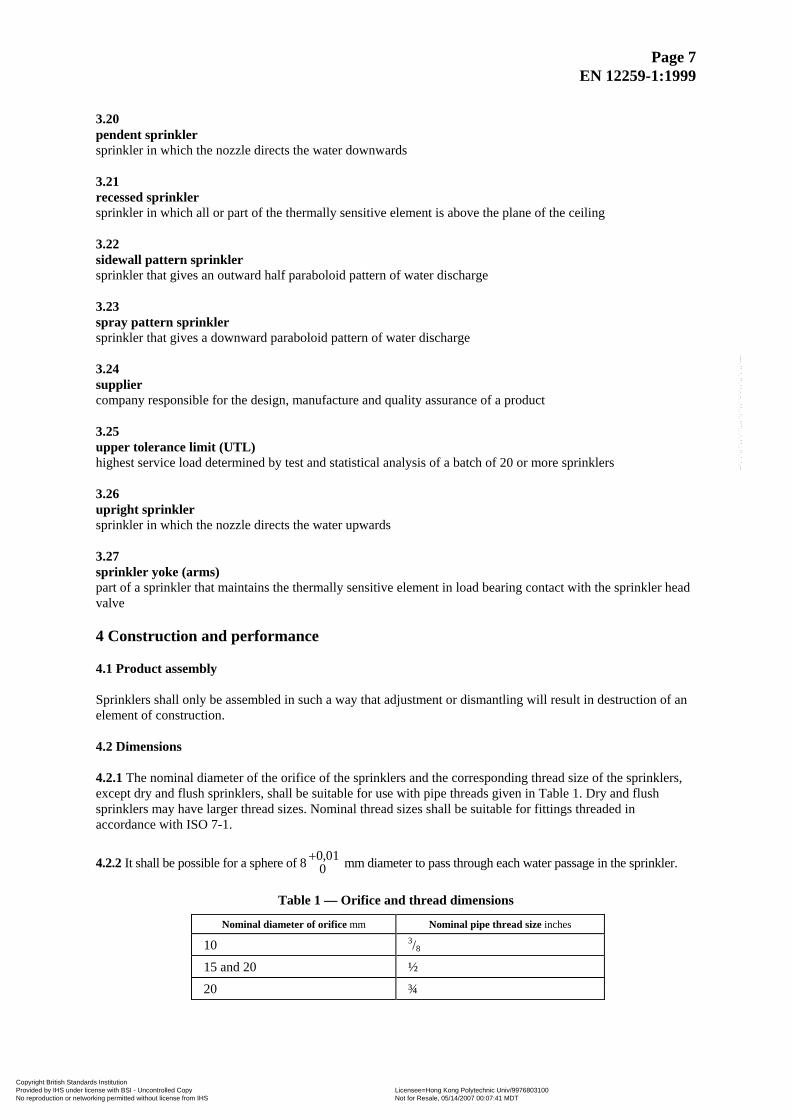
3.20 pendent sprinkler sprinkler in which the nozzle directs the water downwards 3.21 recessed sprinkler sprinkler in which all or part of the thermally sensitive element is above the plane of the ceiling 3.22 sidewall pattern sprinkler sprinkler that gives an outward half paraboloid pattern of water discharge 3.23 spray pattern sprinkler sprinkler that gives a downward paraboloid pattern of water discharge 3.24 supplier company responsible for the design, manufacture and quality assurance of a product 3.25 upper tolerance limit (UTL) highest service load determined by test and statistical analysis of a batch of 20 or more sprinklers 3.26 upright sprinkler sprinkler in which the nozzle directs the water upwards 3.27 sprinkler yoke (arms) part of a sprinkler that maintains the thermally sensitive element in load bearing contact with the sprinkler head valve 4 Construction and performance 4.1 Product assembly Sprinklers shall only be assembled in such a way that adjustment or dismantling will result in destruction of an element of construction. 4.2 Dimensions 4.2.1 The nominal diameter of the orifice of the sprinklers and the corresponding thread size of the sprinklers, except dry and flush sprinklers, shall be suitable for use with pipe threads given in Table 1. Dry and flush sprinklers may have larger thread sizes. Nominal thread sizes shall be suitable for fittings threaded in accordance with ISO 7-1.
4.2.2 It shall be possible for a sphere of 8 mm diameter to pass through each water passage in the sprinkler. +0 010,
Table 1 — Orifice and thread dimensions
Nominal diameter of orifice mm Nominal pipe thread size inches
10 3/8
15 and 20 ½
20 ¾
Copyright British Standards Institution Provided by IHS under license with BSI - Uncontrolled Copy Licensee=Hong Kong Polytechnic Univ/9976803100
Not for Resale, 05/14/2007 00:07:41 MDTNo reproduction or networking permitted without license from IHS
--`,`,`,,``,,`,```,,,``,``,,``-`-`,,`,,`,`,,`---
Page 8 EN 12259-1:1999
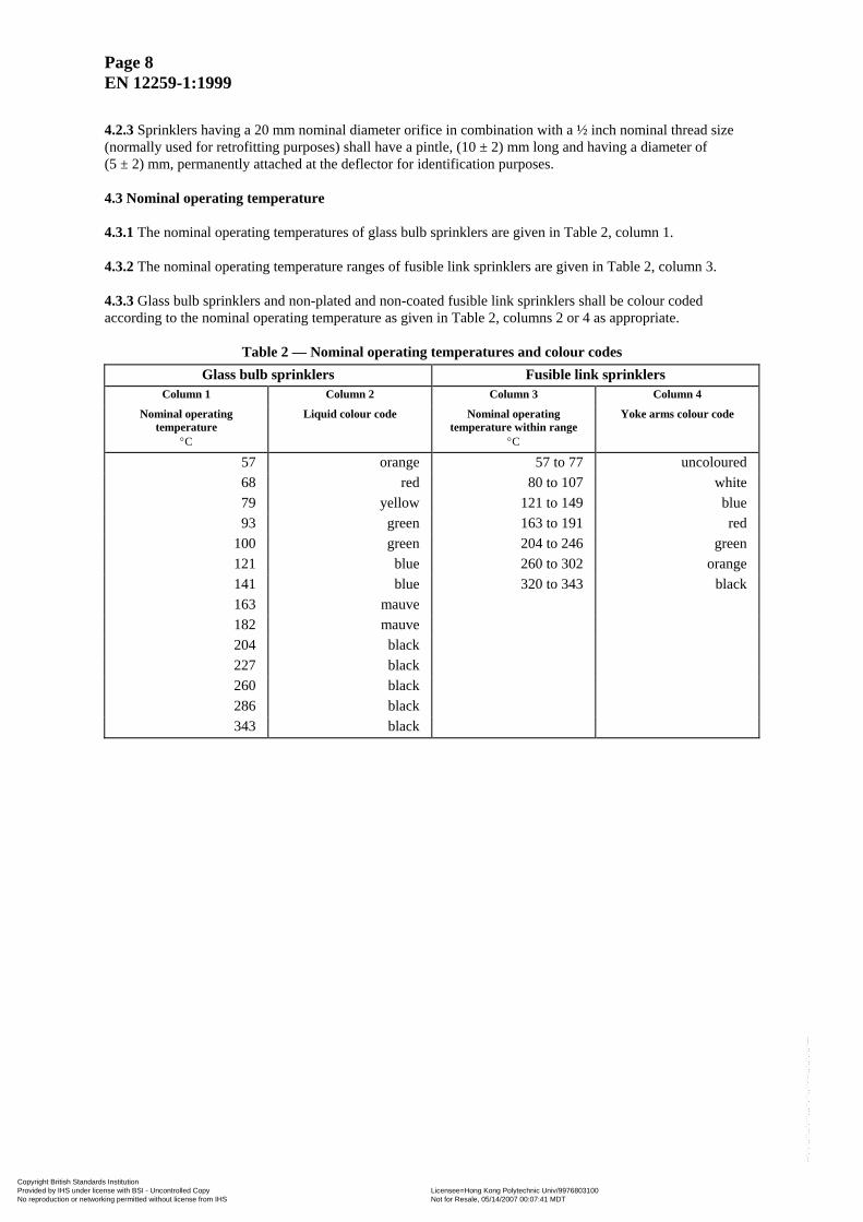
4.2.3 Sprinklers having a 20 mm nominal diameter orifice in combination with a ½ inch nominal thread size (normally used for retrofitting purposes) shall have a pintle, (10 ± 2) mm long and having a diameter of (5 ± 2) mm, permanently attached at the deflector for identification purposes. 4.3 Nominal operating temperature 4.3.1 The nominal operating temperatures of glass bulb sprinklers are given in Table 2, column 1. 4.3.2 The nominal operating temperature ranges of fusible link sprinklers are given in Table 2, column 3. 4.3.3 Glass bulb sprinklers and non-plated and non-coated fusible link sprinklers shall be colour coded according to the nominal operating temperature as given in Table 2, columns 2 or 4 as appropriate.
Table 2 — Nominal operating temperatures and colour codes Glass bulb sprinklers Fusible link sprinklers
Column 1 Column 2 Column 3 Column 4
Nominal operating temperature
Liquid colour code Nominal operating temperature within range
Yoke arms colour code
°C °C
57 orange 57 to 77 uncoloured 68 red 80 to 107 white 79 yellow 121 to 149 blue 93 green 163 to 191 red
100 green 204 to 246 green 121 blue 260 to 302 orange 141 blue 320 to 343 black 163 mauve 182 mauve 204 black 227 black 260 black 286 black 343 black
Copyright British Standards Institution Provided by IHS under license with BSI - Uncontrolled Copy Licensee=Hong Kong Polytechnic Univ/9976803100
Not for Resale, 05/14/2007 00:07:41 MDTNo reproduction or networking permitted without license from IHS
--`,`,`,,``,,`,```,,,``,``,,``-`-`,,`,,`,`,,`---
Page 9 EN 12259-1:1999
4.4 Operating temperatures When testing in accordance with annex B, sprinklers shall operate at a temperature within the range:
[t ± (0,035 t +0,62)] oC
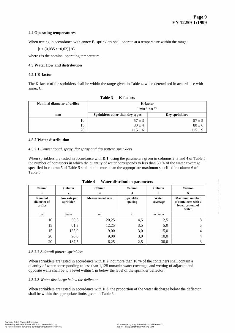
where t is the nominal operating temperature. 4.5 Water flow and distribution 4.5.1 K-factor The K-factor of the sprinklers shall be within the range given in Table 4, when determined in accordance with annex C.
Table 3 — K-factors Nominal diameter of orifice K-factor
l·min-1 ·bar-1/2
mm Sprinklers other than dry types Dry sprinklers
10 57 ± 3 57 ± 5 15 80 ± 4 80 ± 6 20 115 ± 6 115 ± 9
4.5.2 Water distribution 4.5.2.1 Conventional, spray, flat spray and dry pattern sprinklers When sprinklers are tested in accordance with D.1, using the parameters given in columns 2, 3 and 4 of Table 5, the number of containers in which the quantity of water corresponds to less than 50 % of the water coverage specified in column 5 of Table 5 shall not be more than the appropriate maximum specified in column 6 of Table 5.
Table 4 — Water distribution parameters Column Column Column Column Column Column
1 2 3 4 5 6
Nominal diameter of
orifice
Flow rate per sprinkler
Measurement area Sprinkler spacing
Water coverage
Maximum number of containers with a
lower content of water
mm l/min m2 m mm/min
10 50,6 20,25 4,5 2,5 8 15 61,3 12,25 3,5 5,0 5 15 135,0 9,00 3,0 15,0 4 20 90,0 9,00 3,0 10,0 4 20 187,5 6,25 2,5 30,0 3
4.5.2.2 Sidewall pattern sprinklers When sprinklers are tested in accordance with D.2, not more than 10 % of the containers shall contain a quantity of water corresponding to less than 1,125 mm/min water coverage, and wetting of adjacent and opposite walls shall be to a level within 1 m below the level of the sprinkler deflector. 4.5.2.3 Water discharge below the deflector When sprinklers are tested in accordance with D.3, the proportion of the water discharge below the deflector shall be within the appropriate limits given in Table 6.
Copyright British Standards Institution Provided by IHS under license with BSI - Uncontrolled Copy Licensee=Hong Kong Polytechnic Univ/9976803100
Not for Resale, 05/14/2007 00:07:41 MDTNo reproduction or networking permitted without license from IHS
--`,`,`,,``,,`,```,,,``,``,,``-`-`,,`,,`,`,,`---
Page 10 EN 12259-1:1999
Table 5 — Water discharge downwards from the deflector
Type of sprinkler Proportion of water discharged below the deflector
Conventional pattern sprinkler 40 % to 60 %
Spray pattern sprinkler 80 % to 100 %
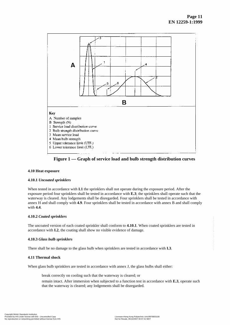
Flat spray sprinkler 85 % to 100 % 4.6 Function 4.6.1 When tested in accordance with E.1 the sprinkler shall open and within 5 s of release of the thermally sensitive element shall operate satisfactorily. Any lodgement of released parts shall be cleared within 60 s of the release of the thermally sensitive element. After testing in accordance with E.1 the sprinkler shall conform to the requirements of 4.5.1 and 4.5.2. 4.6.2 After testing in accordance with E.2 the deflector and its supporting parts shall conform to the requirements of 4.5.2. NOTE In most instances visual examination of the equipment will be sufficient to establish conformity with the requirements of 4.5.2. 4.7 Strength of sprinkler body and deflector 4.7.1 The sprinkler body shall not show permanent elongation of more than 0,2 % between the load-bearing parts when subjected to twice the average service load when tested in accordance with F.1. 4.7.2 The sprinkler deflector and its supporting parts shall withstand an applied force of 70 N without permanent deformation when tested in accordance with F.2. 4.8 Strength of release element 4.8.1 Glass bulb sprinklers When evaluated and tested in accordance with G.1, glass bulb sprinklers shall have:
a) a mean design bulb strength of at least six times the mean design service load; b) a mean bulb strength not less than the mean design bulb strength; c) a mean service load not more than the mean design service load; d) a design lower tolerance limit (DLTL) on the distribution curve of at least two times the design upper
tolerance limit (DUTL) of the service load distribution curve; e) an upper tolerance limit (UTL) less than or equal to the design upper tolerance limit (DUTL); f) a lower tolerance limit (LTL) greater than or equal to the design lower tolerance limit (DLTL)
see Figure 1. 4.8.2Fusible link sprinklers It shall be determined that:
—the temperature sensitive elements withstand a load of 15 times the maximum design load for a period of 100 h, without failure; or —the estimated time to failure of temperature sensitive elements is not less than 876 600 h at the design load, when tested in accordance with G.2.
4.9 Leak resistance The sprinklers shall not show any sign of failure when hydraulically pressure-tested in accordance with annex H.
Copyright British Standards Institution Provided by IHS under license with BSI - Uncontrolled Copy Licensee=Hong Kong Polytechnic Univ/9976803100
Not for Resale, 05/14/2007 00:07:41 MDTNo reproduction or networking permitted without license from IHS
--`,`,`,,``,,`,```,,,``,``,,``-`-`,,`,,`,`,,`---
Page 11 EN 12259-1:1999
Figure 1 — Graph of service load and bulb strength distribution curves
4.10 Heat exposure 4.10.1 Uncoated sprinklers When tested in accordance with I.1 the sprinklers shall not operate during the exposure period. After the exposure period four sprinklers shall be tested in accordance with E.3; the sprinklers shall operate such that the waterway is cleared. Any lodgements shall be disregarded. Four sprinklers shall be tested in accordance with annex H and shall comply with 4.9. Four sprinklers shall be tested in accordance with annex B and shall comply with 4.4. 4.10.2 Coated sprinklers The uncoated version of each coated sprinkler shall conform to 4.10.1. When coated sprinklers are tested in accordance with I.2, the coating shall show no visible evidence of damage. 4.10.3 Glass bulb sprinklers There shall be no damage to the glass bulb when sprinklers are tested in accordance with I.3. 4.11 Thermal shock When glass bulb sprinklers are tested in accordance with annex J, the glass bulbs shall either:
break correctly on cooling such that the waterway is cleared; or remain intact. After immersion when subjected to a function test in accordance with E.3, operate such that the waterway is cleared; any lodgements shall be disregarded.
Copyright British Standards Institution Provided by IHS under license with BSI - Uncontrolled Copy Licensee=Hong Kong Polytechnic Univ/9976803100
Not for Resale, 05/14/2007 00:07:41 MDTNo reproduction or networking permitted without license from IHS
--`,`,`,,``,,`,```,,,``,``,,``-`-`,,`,,`,`,,`---
Page 12 EN 12259-1:1999
4.12 Corrosion 4.12.1 Stress corrosion Sprinklers shall be subjected to a stress corrosion test as described in K.1. Those sprinklers in which cracks, delamination or failure of an operating part is observed shall show no evidence of leakage in the leak resistance test described in K.1. After exposure, when subjected to a function test in accordance with E.3 the sprinkler shall operate such that the waterway is cleared; any lodgements shall be disregarded. Those sprinklers which show evidence of cracking, delamination or failure of a non-operating part shall show no visible evidence of separation of permanently attached parts when subjected to the flowing test described in K.1. 4.12.2 Sulphur dioxide corrosion Sprinklers shall be subjected to a sulphur dioxide corrosion test in accordance with K.2. After exposure, when subjected to a function test in accordance with E.3 the sprinkler shall operate such that the waterway is cleared; any lodgements shall be disregarded. 4.12.3 Salt mist corrosion Sprinklers shall be subjected to a salt mist corrosion test in accordance with K.3. After exposure, when subjected to a function test in accordance with E.3, the sprinkler shall operate such that the waterway is cleared; any lodgements shall be disregarded. 4.12.4 Moist air exposure Sprinklers shall be subjected to moist air exposure in accordance with K.4. After exposure, when subjected to a function test in accordance with E.3, the sprinkler shall operate such that the waterway is cleared; any lodgements shall be disregarded. 4.13 Integrity of sprinkler coatings 4.13.1 Volatile matter in wax and bitumen coating materials Waxes and bitumens used for coating sprinklers shall not contain volatile matter in sufficient quantities to cause loss in mass exceeding 5 % of the mass of the original sample when tested in accordance with L.1. 4.13.2 Coating resistance to low temperature Any coating (wax, bitumen, paint or metallic) on the sprinkler shall not crack or flake when the coated sprinkler is tested in accordance with L.2. 4.14 Water hammer Sprinklers shall not leak when subjected to pressure surges in accordance with annex M. After the test, when subjected to a function test in accordance with E.3, the sprinkler shall operate such that the waterway is cleared; any lodgements shall be disregarded.
Copyright British Standards Institution Provided by IHS under license with BSI - Uncontrolled Copy Licensee=Hong Kong Polytechnic Univ/9976803100
Not for Resale, 05/14/2007 00:07:41 MDTNo reproduction or networking permitted without license from IHS
--`,`,`,,``,,`,```,,,``,``,,``-`-`,,`,,`,`,,`---
Page 13 EN 12259-1:1999
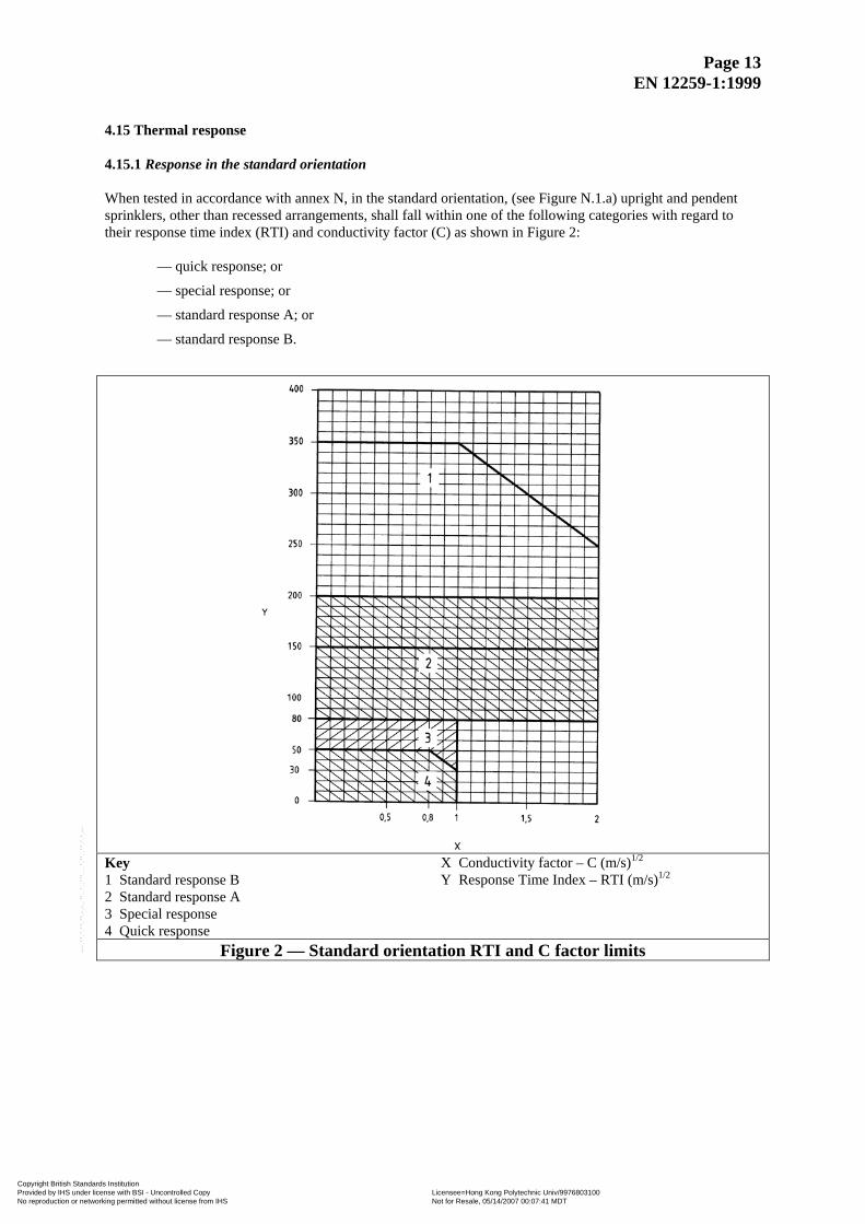
4.15 Thermal response 4.15.1 Response in the standard orientation When tested in accordance with annex N, in the standard orientation, (see Figure N.1.a) upright and pendent sprinklers, other than recessed arrangements, shall fall within one of the following categories with regard to their response time index (RTI) and conductivity factor (C) as shown in Figure 2:
— quick response; or
— special response; or
— standard response A; or
— standard response B.
Key 1 Standard response B 2 Standard response A 3 Special response 4 Quick response
X Conductivity factor – C (m/s)1/2
Y Response Time Index – RTI (m/s)1/2
Figure 2 — Standard orientation RTI and C factor limits
Copyright British Standards Institution Provided by IHS under license with BSI - Uncontrolled Copy Licensee=Hong Kong Polytechnic Univ/9976803100
Not for Resale, 05/14/2007 00:07:41 MDTNo reproduction or networking permitted without license from IHS
--`,`,`,,``,,`,```,,,``,``,,``-`-`,,`,,`,`,,`---
Page 14 EN 12259-1:1999
4.15.2 Response in the unfavourable orientation In the unfavourable orientation the influence of any yoke arm shadow effect shall be limited to a nominal angle of 25° each side of the yoke arm (e.g. maximum 104° of the 360°) as shown in Figure N.1.b). When tested in accordance with annex N in the unfavourable orientation the average RTI values shall not exceed 110 % of the relevant limits given in Figure 2. When calculating the RTI in the unfavourable orientation the C factor from the standard orientation test shall be used. 4.16 Resistance to heat When tested in accordance with annex O, the sprinkler body, deflector and its supporting parts shall show no significant deformation or breakage. 4.17 Resistance to vibration After being subjected to a vibration test in accordance with annex P, the sprinkler shall show no visible evidence of damage, and shall conform to 4.8 and 4.9, and shall function satisfactorily when tested in accordance with E.3. Any lodgements shall be disregarded. 4.18 Resistance to impact After being subjected to the impact test in accordance with annex Q, the sprinkler shall conform to 4.9 and shall function satisfactorily when tested in accordance with E.3. 4.19 Resistance to low temperature The sprinkler shall not operate before the function test, when tested in accordance with annex R. After the test the sprinkler shall show no visible evidence of damage. Following examination, when subjected to a function test in accordance with E.3 the sprinkler shall operate such that the waterway is cleared; any lodgements shall be disregarded.
5 Marking 5.1 General Sprinklers shall be marked with the following:
a) name or trade mark of supplier; and b) model number, catalogue designation or equivalent marking; and c) factory of origin, if manufacture is at two or more factories; and d) letters indicating the type of sprinkler and the mounting position in accordance with Table 7; and e) nominal operating temperature; which shall be stamped, cast, engraved or colour-coded in such a
way that the nominal operating temperature is recognizable even if the sprinkler has operated. In countries where colour-coding of yoke arms of glass bulb sprinklers is required, the colour code given in Table 2 for fusible link sprinklers shall be used; and
NOTE In addition to any colour coding indicating the nominal operating temperature (see 4.3 and Table 2) the nominal operating temperature should be stamped or cast on the fusible element of the fusible link sprinklers.
f) year of manufacture.
NOTE This should be given in a full form, “2000”, or a short form, “00”, and may include the last 3 months of the preceding year and the first 6 months of the following year.
Where the requirements of annex ZA.3 give the same information as above, the requirements of this clause (5) shall be considered to have been met.
Copyright British Standards Institution Provided by IHS under license with BSI - Uncontrolled Copy Licensee=Hong Kong Polytechnic Univ/9976803100
Not for Resale, 05/14/2007 00:07:41 MDTNo reproduction or networking permitted without license from IHS
--`,`,`,,``,,`,```,,,``,``,,``-`-`,,`,,`,`,,`---
Page 15 EN 12259-1:1999
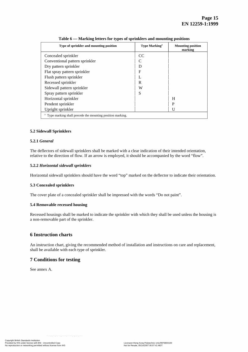
Table 6 — Marking letters for types of sprinklers and mounting positions Type of sprinkler and mounting position Type Markinga Mounting position
marking
Concealed sprinkler CC Conventional pattern sprinkler C Dry pattern sprinkler D Flat spray pattern sprinkler F Flush pattern sprinkler L Recessed sprinkler R Sidewall pattern sprinkler W Spray pattern sprinkler S Horizontal sprinkler H Pendent sprinkler P Upright sprinkler U a Type marking shall precede the mounting position marking.
5.2 Sidewall Sprinklers 5.2.1 General The deflectors of sidewall sprinklers shall be marked with a clear indication of their intended orientation, relative to the direction of flow. If an arrow is employed, it should be accompanied by the word “flow”. 5.2.2 Horizontal sidewall sprinklers Horizontal sidewall sprinklers should have the word “top” marked on the deflector to indicate their orientation. 5.3 Concealed sprinklers The cover plate of a concealed sprinkler shall be impressed with the words “Do not paint”. 5.4 Removable recessed housing Recessed housings shall be marked to indicate the sprinkler with which they shall be used unless the housing is a non-removable part of the sprinkler. 6 Instruction charts An instruction chart, giving the recommended method of installation and instructions on care and replacement, shall be available with each type of sprinkler. 7 Conditions for testing See annex A.
Copyright British Standards Institution Provided by IHS under license with BSI - Uncontrolled Copy Licensee=Hong Kong Polytechnic Univ/9976803100
Not for Resale, 05/14/2007 00:07:41 MDTNo reproduction or networking permitted without license from IHS
--`,`,`,,``,,`,```,,,``,``,,``-`-`,,`,,`,`,,`---
Page 16 EN 12259-1:1999
8 Evaluation of conformity 8.1 General The compliance of a sprinkler with the requirements of this standard shall be demonstrated by:
— initial type testing; — factory production control by the manufacturer; — audit testing.
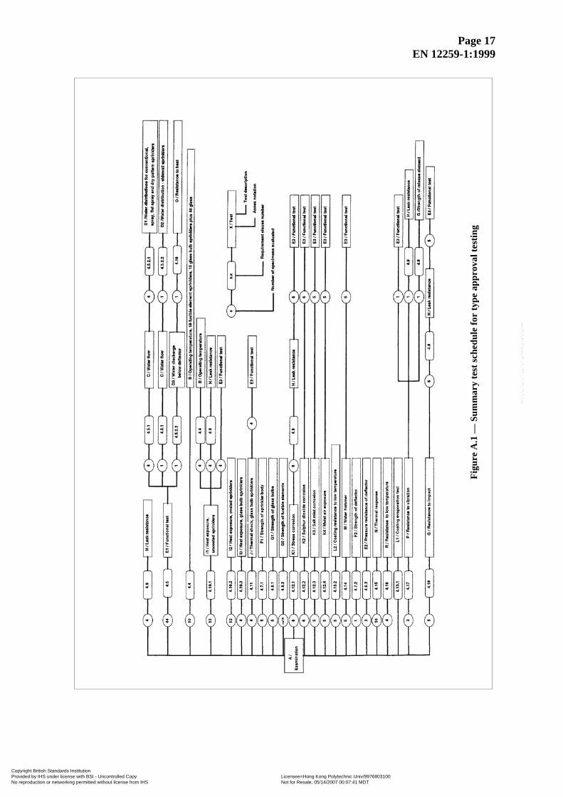
8.2 Initial type testing Initial type testing shall be performed on first application of this standard. Tests previously performed in accordance with the provisions of this standard (same product, characteristics, test method, sampling regime, system of attestation of conformity, etc.) may be taken into account. In addition, initial type testing shall be performed at the beginning of the production of a product type or at the beginning of a new method of production (where these may affect the stated properties). All characteristics given in clause 4 shall be subject to initial type testing. 8.3 Factory production control (FPC) The supplier shall establish, document and maintain an FPC system to ensure that the products placed on the market conform with the stated performance characteristics. The FPC system shall consist of procedures, regular inspections and tests and/or assessments and the use of the results to control raw and other incoming materials or components, equipment, the production process and the product. It shall be sufficiently detailed to ensure the conformity of the product is apparent, ensuring detection of irregularities at the earliest possible stage An FPC system conforming with the requirements of the relevant part(s) of EN ISO 9000, and made specific to the requirements of this standard, shall be considered to satisfy the above requirements The results of inspection, tests or assessments requiring action shall be recorded, as shall any action taken. The action to be taken when control values or criteria are not met shall be recorded. The production control procedure shall be recorded in a manual, which shall be made available if requested. The supplier shall carry out and record the results of production tests a part of the production control. Theses records shall be available if requested. Annex A (normative) Conditions for tests Except where specified otherwise, carry out tests at (20 + 10)oC . Examine sprinklers for visually obvious defects before testing. NOTE The schedule of Figure A.1 should be used for type approval testing.
Copyright British Standards Institution Provided by IHS under license with BSI - Uncontrolled Copy Licensee=Hong Kong Polytechnic Univ/9976803100
Not for Resale, 05/14/2007 00:07:41 MDTNo reproduction or networking permitted without license from IHS
--`,`,`,,``,,`,```,,,``,``,,``-`-`,,`,,`,`,,`---
Page 17 EN 12259-1:1999
Figu
re A
.1 —
Sum
mar
y te
st sc
hedu
le fo
r ty
pe a
ppro
val t
estin
g
Copyright British Standards Institution Provided by IHS under license with BSI - Uncontrolled Copy Licensee=Hong Kong Polytechnic Univ/9976803100
Not for Resale, 05/14/2007 00:07:41 MDTNo reproduction or networking permitted without license from IHS
--`,`,`,,``,,`,```,,,``,``,,``-`-`,,`,,`,`,,`---
Page 18 EN 12259-1:1999
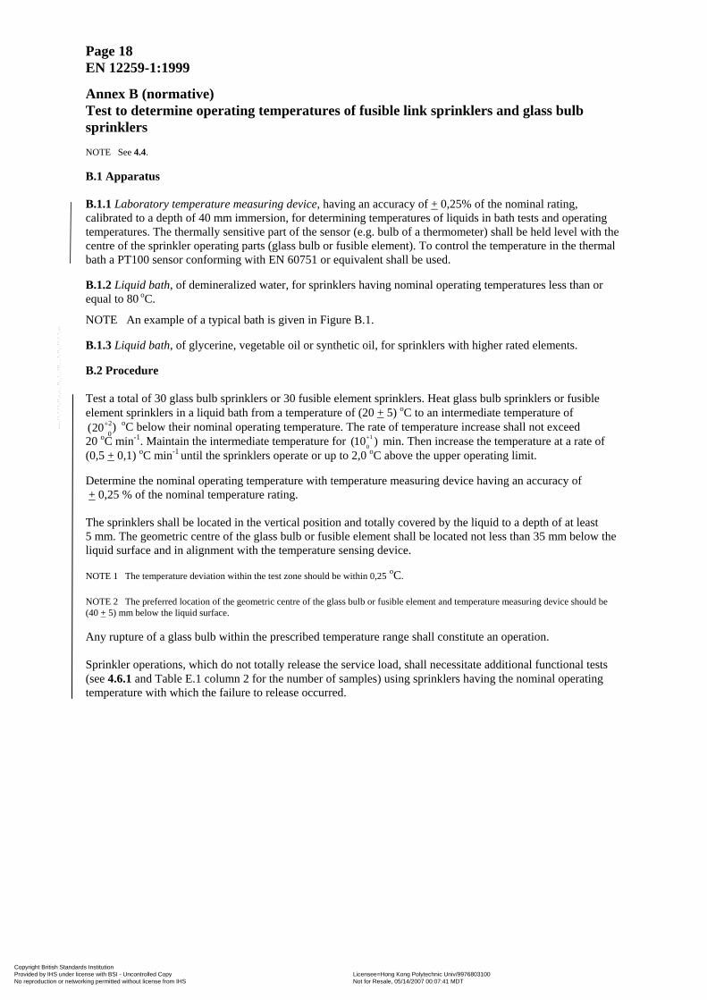
Annex B (normative) Test to determine operating temperatures of fusible link sprinklers and glass bulb sprinklers NOTE See 4.4. B.1 Apparatus B.1.1 Laboratory temperature measuring device, having an accuracy of + 0,25% of the nominal rating, calibrated to a depth of 40 mm immersion, for determining temperatures of liquids in bath tests and operating temperatures. The thermally sensitive part of the sensor (e.g. bulb of a thermometer) shall be held level with the centre of the sprinkler operating parts (glass bulb or fusible element). To control the temperature in the thermal bath a PT100 sensor conforming with EN 60751 or equivalent shall be used. B.1.2 Liquid bath, of demineralized water, for sprinklers having nominal operating temperatures less than or equal to 80 oC.
NOTE An example of a typical bath is given in Figure B.1. B.1.3 Liquid bath, of glycerine, vegetable oil or synthetic oil, for sprinklers with higher rated elements. B.2 Procedure Test a total of 30 glass bulb sprinklers or 30 fusible element sprinklers. Heat glass bulb sprinklers or fusible element sprinklers in a liquid bath from a temperature of (20 + 5) oC to an intermediate temperature of
0 2)(20+
(10 )+
oC below their nominal operating temperature. The rate of temperature increase shall not exceed 20 oC min-1. Maintain the intermediate temperature for 0 min. Then increase the temperature at a rate of (0,5
1
+ 0,1) oC min-1 until the sprinklers operate or up to 2,0 oC above the upper operating limit. Determine the nominal operating temperature with temperature measuring device having an accuracy of + 0,25 % of the nominal temperature rating. The sprinklers shall be located in the vertical position and totally covered by the liquid to a depth of at least 5 mm. The geometric centre of the glass bulb or fusible element shall be located not less than 35 mm below the liquid surface and in alignment with the temperature sensing device. NOTE 1 The temperature deviation within the test zone should be within 0,25 oC. NOTE 2 The preferred location of the geometric centre of the glass bulb or fusible element and temperature measuring device should be (40 + 5) mm below the liquid surface. Any rupture of a glass bulb within the prescribed temperature range shall constitute an operation. Sprinkler operations, which do not totally release the service load, shall necessitate additional functional tests (see 4.6.1 and Table E.1 column 2 for the number of samples) using sprinklers having the nominal operating temperature with which the failure to release occurred.
Copyright British Standards Institution Provided by IHS under license with BSI - Uncontrolled Copy Licensee=Hong Kong Polytechnic Univ/9976803100
Not for Resale, 05/14/2007 00:07:41 MDTNo reproduction or networking permitted without license from IHS
--`,`,`,,``,,`,```,,,``,``,,``-`-`,,`,,`,`,,`---

Page 19 EN 12259-1:1999
Dimensions in millimetres
Key 1 Speed agitator (150 1/min) 2 Temperature measuring device calibrated for immersion at the test level 3 Double wing 100 mm × 20 mm 4 Liquid level 5 Ring to support 10 or 15 sprinklers
6 Mesh screen
7 Typical glass vessel (7l) 8 Immersion heater 9 Glass bulbs 10 Ring to support 50 glass bulbs
Figure B.1 — A typical liquid bath
Copyright British Standards Institution Provided by IHS under license with BSI - Uncontrolled Copy Licensee=Hong Kong Polytechnic Univ/9976803100
Not for Resale, 05/14/2007 00:07:41 MDTNo reproduction or networking permitted without license from IHS
--`,`,`,,``,,`,```,,,``,``,,``-`-`,,`,,`,`,,`---
Page 20 EN 12259-1:1999
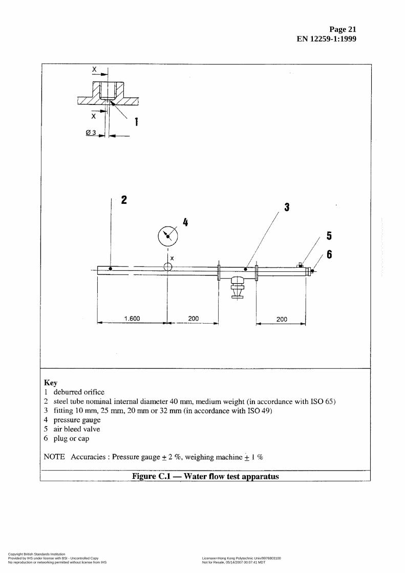
Annex C (normative) Water flow test NOTE 1 See 4.5.1. Mount the sprinkler on a supply pipe together with a means of pressure measurement (see Figure C.1). Bleed the air from the pipe assembly using the bleed valve. Measure the flow rate, by direct measurement of flow rate or by collecting and measuring the weight or volume of water discharged, for water pressures of 0,5 bar to 6,5 bar at the sprinkler head at intervals of (1 ± 2 %) bar. The maximum permissible error of the flow measuring device shall be ±2 % of the value measured. Calculate the K-factor for each pressure interval from the equation (1):
PQ = K
where P is the pressure in bar (bar); Q is the flow rate in litres per minute (l/min).
NOTE 2 During the test, pressures should be corrected for difference in height between the gauge and the outlet orifice of the sprinkler.
Copyright British Standards Institution Provided by IHS under license with BSI - Uncontrolled Copy Licensee=Hong Kong Polytechnic Univ/9976803100
Not for Resale, 05/14/2007 00:07:41 MDTNo reproduction or networking permitted without license from IHS
--`,`,`,,``,,`,```,,,``,``,,``-`-`,,`,,`,`,,`---
Page 21 EN 12259-1:1999
Copyright British Standards Institution Provided by IHS under license with BSI - Uncontrolled Copy Licensee=Hong Kong Polytechnic Univ/9976803100
Not for Resale, 05/14/2007 00:07:41 MDTNo reproduction or networking permitted without license from IHS
--`,`,`,,``,,`,```,,,``,``,,``-`-`,,`,,`,`,,`---
Page 22 EN 12259-1:1999
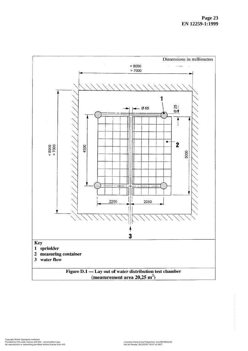
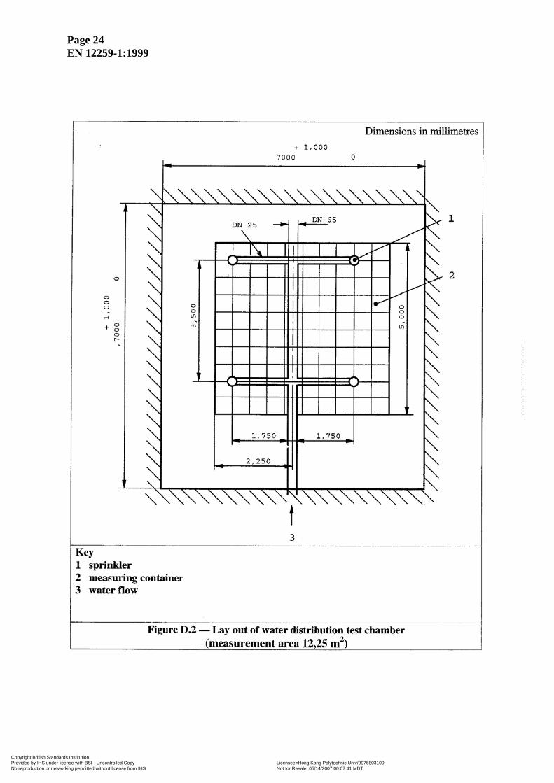
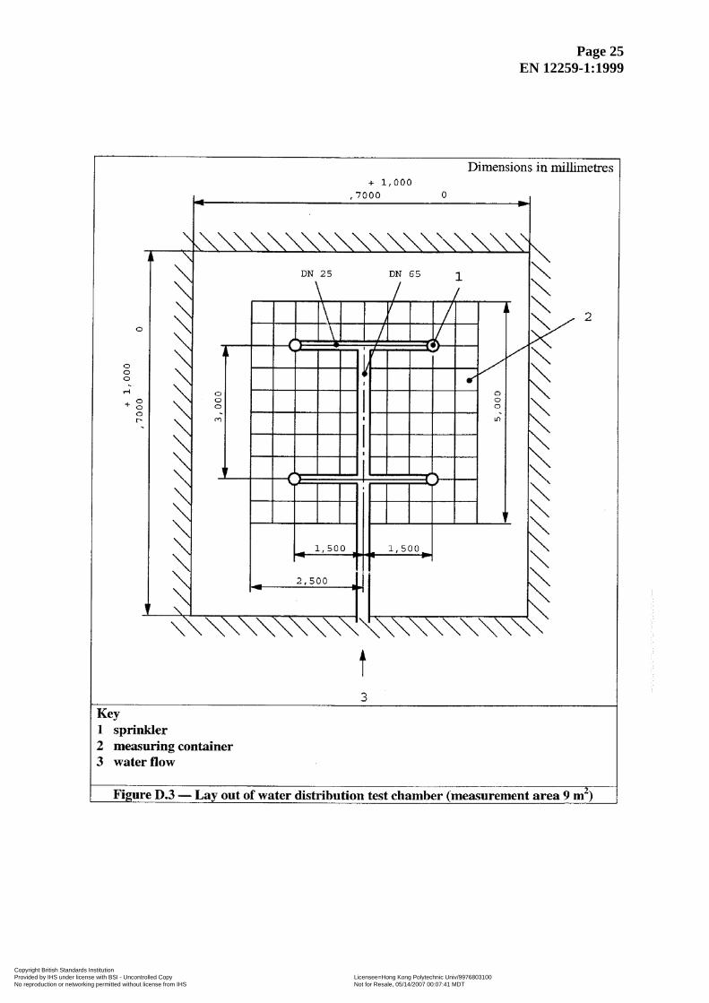
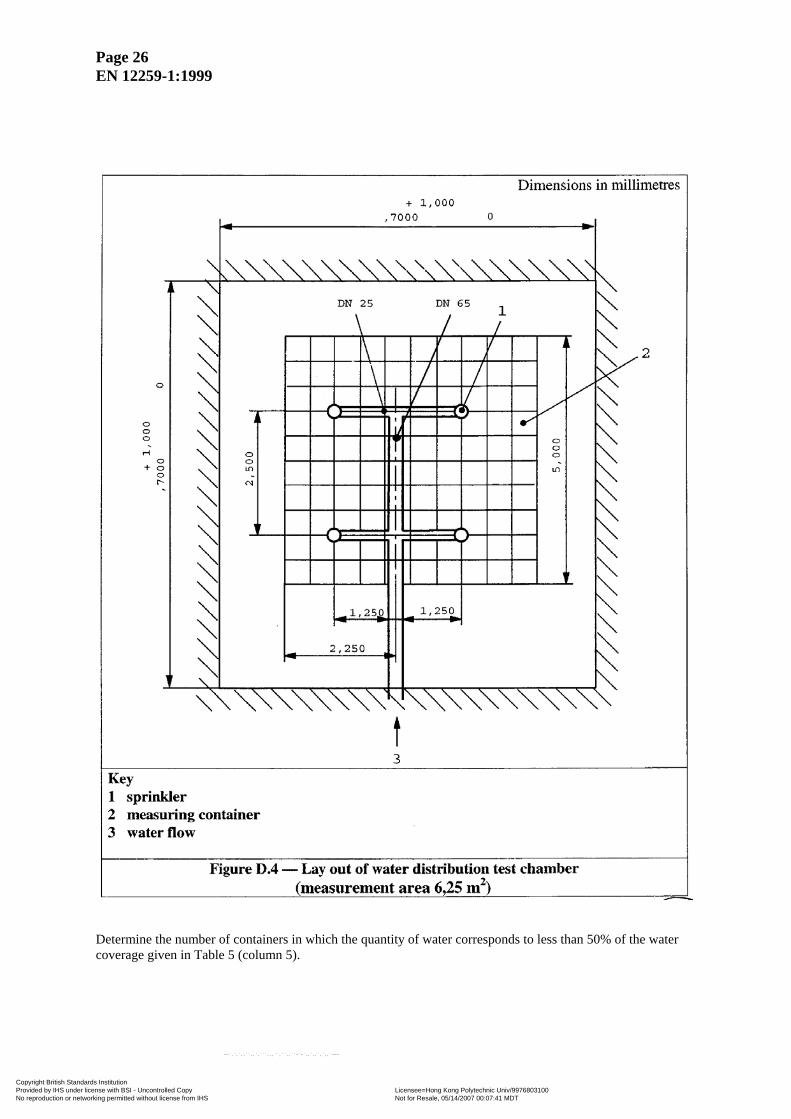
Annex D (normative) Water distribution test NOTE See 4.5.2 D.1 Conventional, spray, flat spray pattern sprinklers (including dry types) Install, in a test chamber of dimensions shown in Figures D.1 to D.4, four sprinklers of the same type, arranged in a square, on piping prepared for this purpose. Use the arrangement of the piping, sprinklers and containers shown in Figures D.1 to D.4. Ensure the yoke arms of the sprinklers are parallel to the supply pipes. Position upright sprinklers with a distance of (50 ± 5) mm and pendent sprinklers with a distance of (275 ± 5) mm between the ceiling and the deflector. Mount flush pattern, concealed and recessed sprinklers in a false ceiling of dimensions not less than (5 × 5) m, arranged symmetrically in the test chamber. Fit the sprinklers directly into the horizontal pipework by means of “tee” or “elbow” fittings. Collect the water for a period which ensures a satisfactory time average measurement has been achieved in each of the designated collection areas. Measure or calculate the volume or weight of water distributed over the measurement area between the four sprinklers by means of square measuring containers with the sides of (500 ± 10) mm, positioned with a distance of (2,7 ± 0,025) m between the ceiling and the upper edge of the measuring containers. Additionally, test the flat spray sprinklers with a distance of (0,3 ± 0,025) m between the deflector and the upper edge of the measuring containers. Position the measuring containers centrally in the room, beneath the four sprinklers as shown in Figures D.1 to D.4.
Copyright British Standards Institution Provided by IHS under license with BSI - Uncontrolled Copy Licensee=Hong Kong Polytechnic Univ/9976803100
Not for Resale, 05/14/2007 00:07:41 MDTNo reproduction or networking permitted without license from IHS
--`,`,`,,``,,`,```,,,``,``,,``-`-`,,`,,`,`,,`---
Page 23 EN 12259-1:1999
Copyright British Standards Institution Provided by IHS under license with BSI - Uncontrolled Copy Licensee=Hong Kong Polytechnic Univ/9976803100
Not for Resale, 05/14/2007 00:07:41 MDTNo reproduction or networking permitted without license from IHS
--`,`,`,,``,,`,```,,,``,``,,``-`-`,,`,,`,`,,`---
Page 24 EN 12259-1:1999
Copyright British Standards Institution Provided by IHS under license with BSI - Uncontrolled Copy Licensee=Hong Kong Polytechnic Univ/9976803100
Not for Resale, 05/14/2007 00:07:41 MDTNo reproduction or networking permitted without license from IHS
--`,`,`,,``,,`,```,,,``,``,,``-`-`,,`,,`,`,,`---
Page 25 EN 12259-1:1999
Copyright British Standards Institution Provided by IHS under license with BSI - Uncontrolled Copy Licensee=Hong Kong Polytechnic Univ/9976803100
Not for Resale, 05/14/2007 00:07:41 MDTNo reproduction or networking permitted without license from IHS
--`,`,`,,``,,`,```,,,``,``,,``-`-`,,`,,`,`,,`---
Page 26 EN 12259-1:1999
Determine the number of containers in which the quantity of water corresponds to less than 50% of the water coverage given in Table 5 (column 5).
Copyright British Standards Institution Provided by IHS under license with BSI - Uncontrolled Copy Licensee=Hong Kong Polytechnic Univ/9976803100
Not for Resale, 05/14/2007 00:07:41 MDTNo reproduction or networking permitted without license from IHS
--`,`,`,,``,,`,```,,,``,``,,``-`-`,,`,,`,`,,`---

Page 27 EN 12259-1:1999
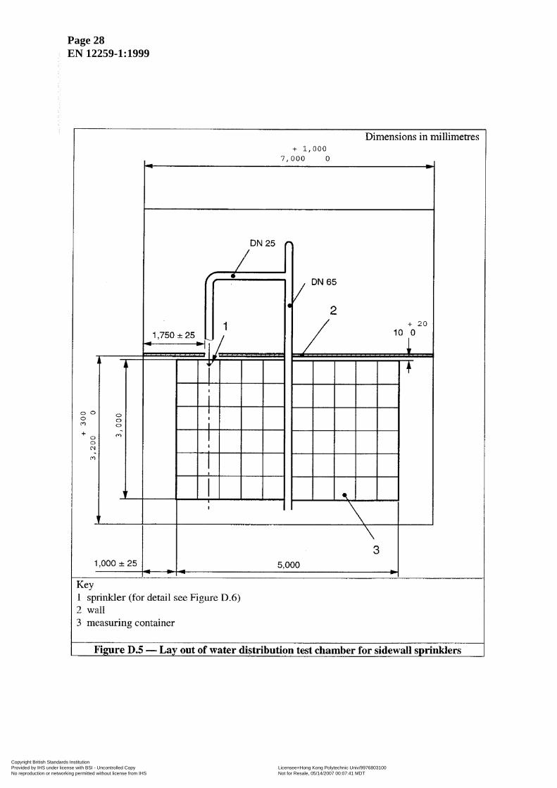
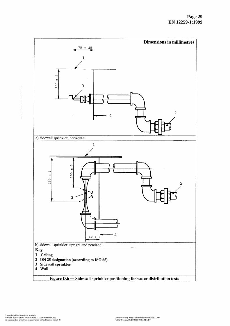
D.2 Sidewall pattern sprinklers Install, in a test chamber of minimum dimensions (3,2 ) m high and of plan area shown in Figure D.5, one sprinkler on a distribution pipe passing through one wall. Ensure that the vertical sprinkler centre line is situated (50 ± 5) mm from that wall. Mount upright or horizontal sprinklers so the deflector is (100 ± 5) mm below the ceiling and pendent sprinklers so that the deflector is 150 mm below the ceiling. Ensure that the horizontal
sprinkler deflector is (75 ± 25) mm from that wall. Ensure that the centre line of sprinklers is at (1 750 ± 25) mm from the adjacent wall. All dimensions are shown in Figures D.5 and D.6.
3,00
+
50+
Collect the water for a period of at least 120 s in square measuring containers with sides of (500 ± 10) mm arranged in the form of a nominal 3 m × 5 m array with its edges (1,0 ± 0,025) m from the adjacent wall and 10 mm to 30 mm from the sprinkler mounting wall. With the sprinkler discharging water at a nominal flow rate of 60 l/min, collect and measure the water in each measuring container and measure the height of the boundary at the lowest point, between the wetted and unwetted parts of the adjacent and opposite walls. Calculate the water distribution and wall wetting profiles which would be produced by two sprinklers nominally 3,5 m apart by overlapping two identical distributions and wall wetting profiles obtained from one test using a single sprinkler.
Copyright British Standards Institution Provided by IHS under license with BSI - Uncontrolled Copy Licensee=Hong Kong Polytechnic Univ/9976803100
Not for Resale, 05/14/2007 00:07:41 MDTNo reproduction or networking permitted without license from IHS
--`,`,`,,``,,`,```,,,``,``,,``-`-`,,`,,`,`,,`---
Page 28 EN 12259-1:1999
Copyright British Standards Institution Provided by IHS under license with BSI - Uncontrolled Copy Licensee=Hong Kong Polytechnic Univ/9976803100
Not for Resale, 05/14/2007 00:07:41 MDTNo reproduction or networking permitted without license from IHS
--`,`,`,,``,,`,```,,,``,``,,``-`-`,,`,,`,`,,`---
Page 29 EN 12259-1:1999
Copyright British Standards Institution Provided by IHS under license with BSI - Uncontrolled Copy Licensee=Hong Kong Polytechnic Univ/9976803100
Not for Resale, 05/14/2007 00:07:41 MDTNo reproduction or networking permitted without license from IHS
--`,`,`,,``,,`,```,,,``,``,,``-`-`,,`,,`,`,,`---
Page 30 EN 12259-1:1999
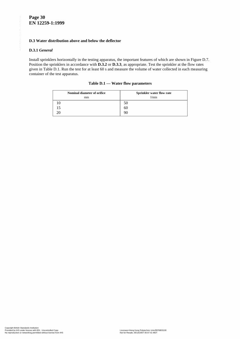
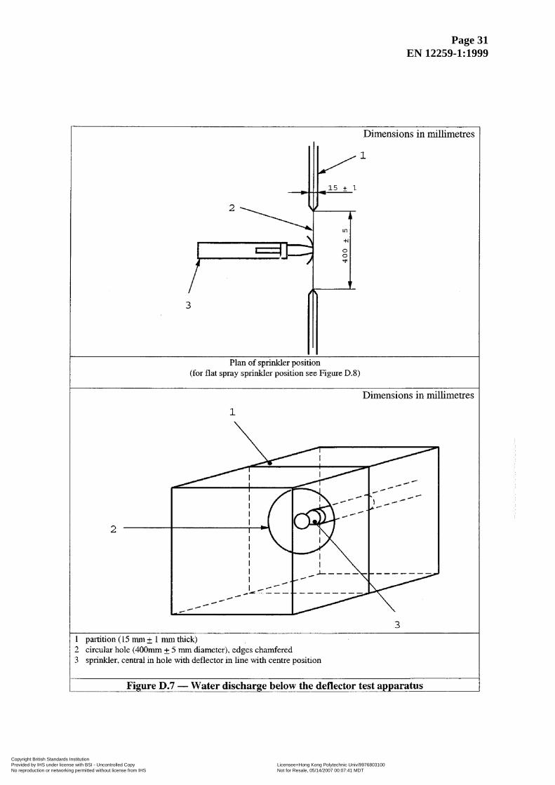
D.3 Water distribution above and below the deflector D.3.1 General Install sprinklers horizontally in the testing apparatus, the important features of which are shown in Figure D.7. Position the sprinklers in accordance with D.3.2 or D.3.3, as appropriate. Test the sprinkler at the flow rates given in Table D.1. Run the test for at least 60 s and measure the volume of water collected in each measuring container of the test apparatus.
Table D.1 — Water flow parameters
Nominal diameter of orifice Sprinkler water flow rate mm l/min
10 50 15 60 20 90
Copyright British Standards Institution Provided by IHS under license with BSI - Uncontrolled Copy Licensee=Hong Kong Polytechnic Univ/9976803100
Not for Resale, 05/14/2007 00:07:41 MDTNo reproduction or networking permitted without license from IHS
--`,`,`,,``,,`,```,,,``,``,,``-`-`,,`,,`,`,,`---
Page 31 EN 12259-1:1999
Copyright British Standards Institution Provided by IHS under license with BSI - Uncontrolled Copy Licensee=Hong Kong Polytechnic Univ/9976803100
Not for Resale, 05/14/2007 00:07:41 MDTNo reproduction or networking permitted without license from IHS
--`,`,`,,``,,`,```,,,``,``,,``-`-`,,`,,`,`,,`---
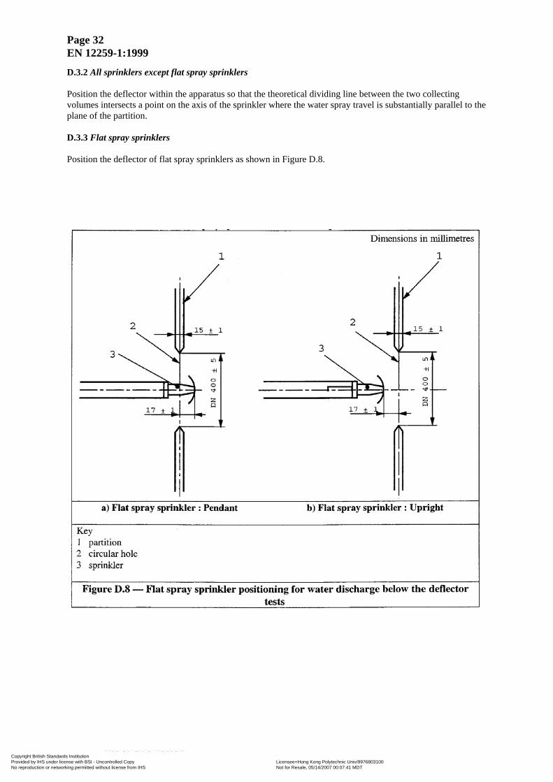
Page 32 EN 12259-1:1999
D.3.2 All sprinklers except flat spray sprinklers Position the deflector within the apparatus so that the theoretical dividing line between the two collecting volumes intersects a point on the axis of the sprinkler where the water spray travel is substantially parallel to the plane of the partition. D.3.3 Flat spray sprinklers Position the deflector of flat spray sprinklers as shown in Figure D.8.
Copyright British Standards Institution Provided by IHS under license with BSI - Uncontrolled Copy Licensee=Hong Kong Polytechnic Univ/9976803100
Not for Resale, 05/14/2007 00:07:41 MDTNo reproduction or networking permitted without license from IHS
--`,`,`,,``,,`,```,,,``,``,,``-`-`,,`,,`,`,,`---
Page 33 EN 12259-1:1999
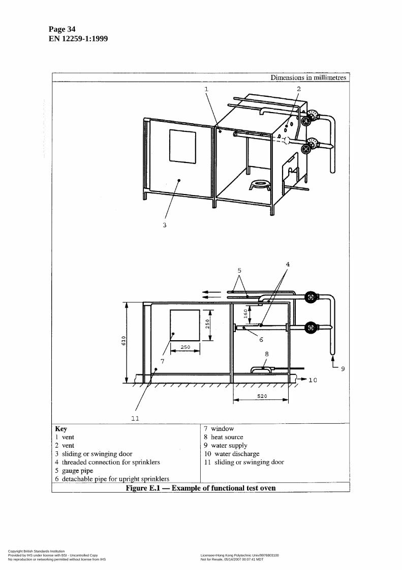
Annex E (normative) Functional test NOTE See 4.6. E.1 Heat the sprinklers, including dry sprinklers that can be accommodated, in the functional test oven shown in Figure E.1. Whilst being heated, subject the inlet to water pressure as given in Table E.1. Increase the temperature at the sprinkler at a rate equivalent to (400 ± 20) °C in not more than 3 min. Heat sprinklers having higher nominal operating temperatures than can be accommodated in the functional test oven, and other dry sprinklers, using a suitable heat source. Continue heating until the sprinkler has operated. Test every sprinkler type and size in each normal mounting position and at the pressure given in Table E.1. Not less than 11 sprinklers of each temperature rating shall be tested.
Table E.1 — Functional test parameters
Test Pressure Minimum quantity tested
Minimum for each operating
temperature
Maximum lodgement rate
bar
0,35 ± 0,05 12 3 1 per 12 3,5 ± 0,1 16 4 1 per 32 12,0 ± 0, 1 16 4
Ensure that the flowing pressure is at least 75 % of initial operating pressure. Measure the oven temperature local to the sprinkler. Lodgement is considered to have occurred when one or more of the released parts lodge in the deflector frame assembly in such a way as to cause the water distribution to be significantly impeded for a period of more than 1 min. E.2 To check the strength of the deflector, submit sprinklers to a flow test at a pressure of (12 ± 0,1) bar. Allow the water to flow at a running pressure of (12 ± 0,1) bar for a period of 45 min.
01+
E.3 Verification functional test Heat sprinklers, including dry sprinklers that can be accommodated in the functional test oven shown in Figure E.1. Increase the temperature at the sprinkler at a rate equivalent to (400 ± 20) °C in not more than 3 minutes. Heat dry sprinklers that cannot be accommodated in the test oven using a suitable heat source. Continue heating until the sprinkler has operated. Whilst the sprinkler is being heated, subject the sprinkler inlet to a water pressure of (0,35 ± 0,05) bar unless stipulated otherwise in the appropriate test procedure. Test the type, size and number of sprinklers specified in the appropriate test procedure and establish that the pass criteria is achieved.
Copyright British Standards Institution Provided by IHS under license with BSI - Uncontrolled Copy Licensee=Hong Kong Polytechnic Univ/9976803100
Not for Resale, 05/14/2007 00:07:41 MDTNo reproduction or networking permitted without license from IHS
--`,`,`,,``,,`,```,,,``,``,,``-`-`,,`,,`,`,,`---
Page 34 EN 12259-1:1999
Copyright British Standards Institution Provided by IHS under license with BSI - Uncontrolled Copy Licensee=Hong Kong Polytechnic Univ/9976803100
Not for Resale, 05/14/2007 00:07:41 MDTNo reproduction or networking permitted without license from IHS
--`,`,`,,``,,`,```,,,``,``,,``-`-`,,`,,`,`,,`---
Page 35 EN 12259-1:1999
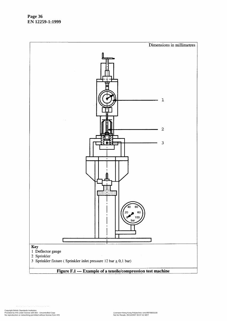
Annex F (normative) Strength of sprinkler body and deflector tests NOTE See 4.7. F.1 Measure the service load by securely installing the sprinkler in a tensile/compression test machine and apply an equivalent of a hydraulic pressure of (12 ± 0,1) bar at the inlet. Use an indicator capable of reading deflection to an accuracy of 0,001 mm to measure any change in length of the sprinkler body between the load bearing points. Preferably avoid or take into account movement of the sprinkler shank thread in the threaded bush of the test machine. Zero the deflection measuring indicator, see Figure F.1. Release the hydraulic pressure and remove the heat responsive element of the sprinkler by a suitable method. When the sprinkler is at room temperature, make a second measurement using the indicator. Then apply an increasing mechanical load to the sprinkler, at a rate not exceeding 5 000 N/min, until the indicator reading at the deflector end of the sprinkler returns to the zero value achieved under the hydrostatic load. Record the mechanical load necessary to achieve this as the service load. Conduct this test on five sprinklers and take the arithmetic mean of the results as the average service load. Increase the applied load progressively at a rate not exceeding 5 000 N/min until twice the average service load has been applied. Maintain this load for (15 ± 5) s. Remove the load and measure any permanent elongation of the sprinkler body. F.2 Apply a force of 70 N to the deflector by means of a flat metal plate, having a contact edge of at least
15 mm, and examine the deflector for permanent deformation. 010+
05+
NOTE This force should not be applied exclusively to the tines.
Copyright British Standards Institution Provided by IHS under license with BSI - Uncontrolled Copy Licensee=Hong Kong Polytechnic Univ/9976803100
Not for Resale, 05/14/2007 00:07:41 MDTNo reproduction or networking permitted without license from IHS
--`,`,`,,``,,`,```,,,``,``,,``-`-`,,`,,`,`,,`---
Page 36 EN 12259-1:1999
Copyright British Standards Institution Provided by IHS under license with BSI - Uncontrolled Copy Licensee=Hong Kong Polytechnic Univ/9976803100
Not for Resale, 05/14/2007 00:07:41 MDTNo reproduction or networking permitted without license from IHS
--`,`,`,,``,,`,```,,,``,``,,``-`-`,,`,,`,`,,`---
Page 37 EN 12259-1:1999
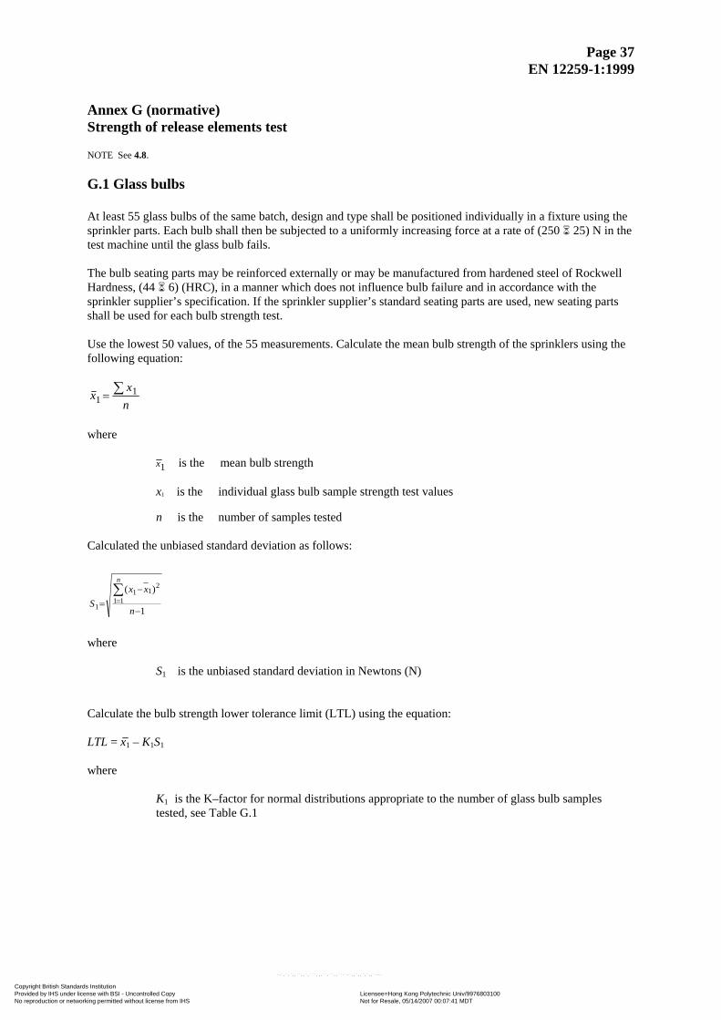
Annex G (normative) Strength of release elements test NOTE See 4.8. G.1 Glass bulbs At least 55 glass bulbs of the same batch, design and type shall be positioned individually in a fixture using the sprinkler parts. Each bulb shall then be subjected to a uniformly increasing force at a rate of (250 25) N in the test machine until the glass bulb fails. The bulb seating parts may be reinforced externally or may be manufactured from hardened steel of Rockwell Hardness, (44 6) (HRC), in a manner which does not influence bulb failure and in accordance with the sprinkler supplier’s specification. If the sprinkler supplier’s standard seating parts are used, new seating parts shall be used for each bulb strength test. Use the lowest 50 values, of the 55 measurements. Calculate the mean bulb strength of the sprinklers using the following equation:
x1 nx∑= 1
where
x1 is the mean bulb strength x1 is the individual glass bulb sample strength test values n is the number of samples tested
Calculated the unbiased standard deviation as follows:
1
)(11
211
1 −
−=∑=
n
xxS
n
where
S1 is the unbiased standard deviation in Newtons (N)
Calculate the bulb strength lower tolerance limit (LTL) using the equation: LTL = x1 – K1S1 where
K1 is the K–factor for normal distributions appropriate to the number of glass bulb samples tested, see Table G.1
Copyright British Standards Institution Provided by IHS under license with BSI - Uncontrolled Copy Licensee=Hong Kong Polytechnic Univ/9976803100
Not for Resale, 05/14/2007 00:07:41 MDTNo reproduction or networking permitted without license from IHS
--`,`,`,,``,,`,```,,,``,``,,``-`-`,,`,,`,`,,`---
Page 38 EN 12259-1:1999
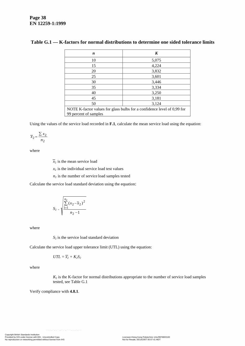
Table G.1 — K-factors for normal distributions to determine one sided tolerance limits
n K
10 5,075 15 4,224 20 3,832 25 3,601 30 3,446 35 3,334 40 3,250 45 3,181 50 3,124
NOTE K-factor values for glass bulbs for a confidence level of 0,99 for 99 percent of samples
Using the values of the service load recorded in F.1, calculate the mean service load using the equation:
2
22 n
xx
∑=
where
x2 is the mean service load
x2 is the individual service load test values
n2 is the number of service load samples tested
Calculate the service load standard deviation using the equation:
S2 = 1
)(
2
11
222
2
−
−∑=
n
xxn
where
S2 is the service load standard deviation Calculate the service load upper tolerance limit (UTL) using the equation:
UTL = x2 + K2S2
where
K2 is the K-factor for normal distributions appropriate to the number of service load samples tested, see Table G.1
Verify compliance with 4.8.1.
Copyright British Standards Institution Provided by IHS under license with BSI - Uncontrolled Copy Licensee=Hong Kong Polytechnic Univ/9976803100
Not for Resale, 05/14/2007 00:07:41 MDTNo reproduction or networking permitted without license from IHS
--`,`,`,,``,,`,```,,,``,``,,``-`-`,,`,,`,`,,`---
Page 39 EN 12259-1:1999
G.2 Fusible links Subject fusible links to a constant load in excess of the design load (Ld), producing failure at approximately 1 000 h. Undertake the test with at least 10 links at different constant loads for loads not exceeding 15 times the maximum design load, reject abnormal failures. Using the times to failure/load values produced by the tests, plot a full logarithmic regression curve using the method of least squares, and from this calculate the loads to failure at 1 h (Lo) and 1 000 h (Lm), where:
Ld ≤ 1,02 o
2m
LL
Condition the test samples at (20 3) °C prior to loading and maintain within these temperature limits throughout the test. Annex H (normative) Leak resistance test NOTE See 4.9. Subject the sprinklers to water pressure of (30 ± 1) bar at the inlet. Increase the pressure from zero to (30 ± 1) bar at a rate not exceeding 1 bar/s, maintain the pressure at (30 ± 1) bar for a period of 3 min and then allow it to fall to 0 bar. After the pressure has dropped to 0 bar, increase it to (0,5 ± 0,1) bar in
not more than 5 s. Maintain this pressure for 15 s, and then increase it to (10 ± 0,5) bar at a rate not exceeding
1 bar/s and maintain it for 15 s. Examine the sprinkler for evidence of leakage during the test.
10+
05+
05+
Annex I (normative) Heat exposure NOTE See 4.10. I.1 Uncoated sprinklers Expose twelve uncoated sprinklers for a period of 90 days in an oven at a temperature that is 11 °C below the nominal operating temperature or at the test temperature shown in Table I.1, whichever is lower, but not less than 49 °C. If the service load is dependent on the service pressure apply an inlet pressure of (12 ± 0,1) bar during the test. After exposure, cool the sprinklers to ambient temperature; then test 4 sprinklers in accordance with each of the test procedures in E.3, annex B and annex H. If one or more sprinklers fail a test, expose at least eight additional sprinklers as described above and subject to the test in which the failure occurred. All of the additional sprinklers shall pass the test.
10+ 2
0+
Copyright British Standards Institution Provided by IHS under license with BSI - Uncontrolled Copy Licensee=Hong Kong Polytechnic Univ/9976803100
Not for Resale, 05/14/2007 00:07:41 MDTNo reproduction or networking permitted without license from IHS
--`,`,`,,``,,`,```,,,``,``,,``-`-`,,`,,`,`,,`---
Page 40 EN 12259-1:1999
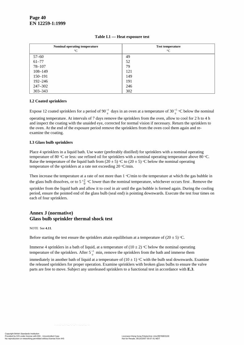
Table I.1 — Heat exposure test
Nominal operating temperature Test temperature
°C °C
57–60 49 61–77 52 78–107 79 108–149 121 150–191 149 192–246 191 247–302 246 303–343 302
I.2 Coated sprinklers Expose 12 coated sprinklers for a period of 90 days in an oven at a temperature of 30 °C below the nominal
operating temperature. At intervals of 7 days remove the sprinklers from the oven, allow to cool for 2 h to 4 h and inspect the coating with the unaided eye, corrected for normal vision if necessary. Return the sprinklers to the oven. At the end of the exposure period remove the sprinklers from the oven cool them again and re-examine the coating.
01+
05+
I.3 Glass bulb sprinklers Place 4 sprinklers in a liquid bath. Use water (preferably distilled) for sprinklers with a nominal operating temperature of 80 °C or less: use refined oil for sprinklers with a nominal operating temperature above 80 °C. Raise the temperature of the liquid bath from (20 ± 5) °C to (20 ± 5) °C below the nominal operating temperature of the sprinklers at a rate not exceeding 20 °C/min. Then increase the temperature at a rate of not more than 1 °C/min to the temperature at which the gas bubble in the glass bulb dissolves, or to 5 °C lower than the nominal temperature, whichever occurs first . Remove the sprinkler from the liquid bath and allow it to cool in air until the gas bubble is formed again. During the cooling period, ensure the pointed end of the glass bulb (seal end) is pointing downwards. Execute the test four times on each of four sprinklers.
20
+
Annex J (normative) Glass bulb sprinkler thermal shock test NOTE See 4.11. Before starting the test ensure the sprinklers attain equilibrium at a temperature of (20 ± 5) °C. Immerse 4 sprinklers in a bath of liquid, at a temperature of (10 ± 2) °C below the nominal operating temperature of the sprinklers. After 5 min, remove the sprinklers from the bath and immerse them
immediately in another bath of liquid at a temperature of (10 ± 1) °C with the bulb seal downwards. Examine the released sprinklers for proper operation. Examine sprinklers with broken glass bulbs to ensure the valve parts are free to move. Subject any unreleased sprinklers to a functional test in accordance with E.3.
01+
Copyright British Standards Institution Provided by IHS under license with BSI - Uncontrolled Copy Licensee=Hong Kong Polytechnic Univ/9976803100
Not for Resale, 05/14/2007 00:07:41 MDTNo reproduction or networking permitted without license from IHS
--`,`,`,,``,,`,```,,,``,``,,``-`-`,,`,,`,`,,`---
Page 41 EN 12259-1:1999
Annex K (normative) Corrosion tests NOTE See 4.12. K.1 Stress corrosion test K.1.1 Reagents Aqueous ammonia solution, density 0,94 g/cm3. K.1.2 Apparatus Glass container, of volume 0,01 m3 to 0,03 m3 with a sealable lid, containing a means of supporting the sprinklers under test and a means of preventing condensate dripping onto them, and fitted with a capillary tube, venting to atmosphere, to prevent the build-up of pressure. K.1.3 Procedure Put aqueous ammonia solution into the container, using 0,01 ml/cm3 of container volume to give an atmosphere in the container consisting of approximately 35 % ammonia, 5 % water vapour and 60 % air. Test six sprinklers. Degrease the sprinklers, seal the inlet of each sprinkler with a cap of non-reactive material e.g. plastics, and place them in the container, supporting them approximately 40 mm above the surface of the ammonia solution. Seal the container and maintain at a temperature of (34 ± 2) °C for 10 days. Top up the ammonia solution at
intervals to maintain the level. 0
250,+
After exposure, rinse and dry the sprinklers, and carry out a detailed visual examination. If cracks, delamination or failure of any operating part are observed, subject the sprinkler(s) to a leak resistance test in accordance with H at (12 ± 0,1) bar for 1 min. After the leak resistance test, subject the sprinklers to a function test in
accordance with E.3 at an inlet water pressure of (0,35 ± 0,05) bar. 0
250,+
Subject sprinklers showing cracking, delamination or failure of any non-operating part, after removal of the operating parts, to a flowing pressure of (12 ± 0,1) bar for 1 min, and examine for visible evidence of
separation of permanently attached parts. 0
250,+
K.2 Sulphur dioxide corrosion test K.2.1 Reagents for apparatus of 5 l volume K.2.1.1 (500 ± 5) ml of aqueous solution of sodium thiosulphate of (0,161 ± 0,001) M concentration. NOTE This may be prepared using (20 ± 0,1) g of analytical grade sodium thiosulphate pentahydrate crystals (Na2S2O3· 5H2O) made up to 500 ml distilled or deionized water in a volumetric flask at 20 °C. K.2.1.2 (1 000 ± 5) ml of dilute aqueous sulphuric acid of (0,078 ± 0,005) M concentration. NOTE This may be prepared using (156 ± 1) ml analytical grade 0,5 M sulphuric acid solution made up to 1 000 ml with distilled or deionized water in a volumetric flask at 20 °C.
Copyright British Standards Institution Provided by IHS under license with BSI - Uncontrolled Copy Licensee=Hong Kong Polytechnic Univ/9976803100
Not for Resale, 05/14/2007 00:07:41 MDTNo reproduction or networking permitted without license from IHS
--`,`,`,,``,,`,```,,,``,``,,``-`-`,,`,,`,`,,`---
Page 42 EN 12259-1:1999
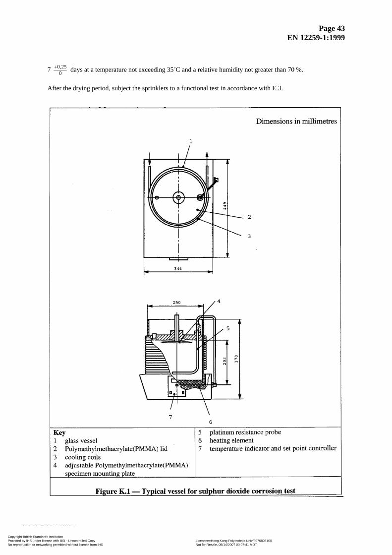
K.2.2 Apparatus Glass vessel, as shown in Figure K.1, of 5 l or 10 l volume, made of heat resistant glass with a corrosion-resistant lid, shaped such that the condensate does not drip onto the sprinklers during the test, fitted with a cooling coil to cool the side walls of the vessel, as shown in Figure K.1 and an electrical heating device regulated by a temperature sensor placed centrally (160 ± 20) mm above the bottom of the vessel. NOTE If a 10 l vessel is used, the volumes of sodium thiosulphate and sulphuric acid given in K.2.1 need to be doubled. K.2.3 Procedure Expose six sprinklers for two periods of eight days each. Place the sodium thiosulphate solution in the vessel. Seal the inlet of each sprinkler with a cap of non-reactive material e.g. plastics, and suspend the sprinklers freely in the normal mounting position inside the vessel under the lid. Adjust the temperature inside the vessel to (45 ± 3) °C and the flow of water through the cooling coil to give a temperature at the outflow below 30 °C. Maintain these temperatures throughout the test. NOTE This combination of temperatures is intended to encourage condensation on the surfaces of the sprinklers. Add (20 ± 0,5) ml of dilute sulphuric acid to the vessel each day. After 8 days remove the sprinklers from
the vessel and empty and clean the vessel. Repeat the above procedure for a second period of 8 days. 0
250,+
0250,+
After a total of 16 days remove the sprinklers from the vessel and allow them to dry for
050,+
7 days at a temperature not exceeding 35 °C and a relative humidity not greater than 70 %. 0
250,+
After the drying period, subject the sprinklers to a functional test in accordance with E.3.
Copyright British Standards Institution Provided by IHS under license with BSI - Uncontrolled Copy Licensee=Hong Kong Polytechnic Univ/9976803100
Not for Resale, 05/14/2007 00:07:41 MDTNo reproduction or networking permitted without license from IHS
--`,`,`,,``,,`,```,,,``,``,,``-`-`,,`,,`,`,,`---
Page 43 EN 12259-1:1999
7 025,0+ days at a temperature not exceeding 35˚C and a relative humidity not greater than 70 %.
After the drying period, subject the sprinklers to a functional test in accordance with E.3.
Copyright British Standards Institution Provided by IHS under license with BSI - Uncontrolled Copy Licensee=Hong Kong Polytechnic Univ/9976803100
Not for Resale, 05/14/2007 00:07:41 MDTNo reproduction or networking permitted without license from IHS
--`,`,`,,``,,`,```,,,``,``,,``-`-`,,`,,`,`,,`---
Page 44 EN 12259-1:1999
K.3 Salt mist corrosion test K.3.1 Reagents Sodium chloride solution, consisting of (20 ± 1) % (m/m) sodium chloride in distilled water, pH between 6,5 and 7,2 and having a density between 1,126 g/ml and 1,157 g/ml at (35 ± 2) °C. K.3.2 Apparatus Fog chamber, of minimum volume 0,43 m3, fitted with a recirculating reservoir and aspirating nozzles to deliver a salt spray, and means for sampling and controlling the atmosphere in the chamber. K.3.3 Procedure Test five sprinklers. Fill each sprinkler with deionized water and seal the inlet by means of a plastic cap. Support the sprinklers in the fog chamber in their normal operating position, and expose them to a salt spray by supplying the sodium chloride solution through the nozzles at a pressure of between 0,7 bar and 1,7 bar, while maintaining the temperature in the exposure zone at (35 ± 2) °C. Ensure that solution running off the sprinklers is collected and not returned to the reservoir for recirculation. Collect salt mist from at least two points in the exposure zone and measure the rate of application and the salt concentration. Ensure, for each 80 cm3 of collection area, a collection rate of 1 ml/h to 2 ml/h over a period of 16 h.
0250,+
Expose sprinklers intended for installation in normal atmospheres for a period of 10 days. Expose
sprinklers intended for installation in corrosive atmospheres for a period of 30 days. 0
250,+
050,+
After exposure, remove sprinklers from the fog chamber and allow to dry for 7 days at a temperature not
exceeding 35 °C and at a relative humidity not greater than 70 %. After the drying period, subject the sprinklers to a functional test in accordance with E.3.
0250,+
K.4 Moist air atmosphere test Test five sprinklers. Install the sprinklers on a pipe manifold containing deionized water. Place the entire manifold in an enclosure at a temperature of (95 ± 4) °C and a relative humidity of (98 ± 2) % for 90 days.
01+
After this period, remove the sprinklers and subject them to a functional test in accordance with E.3. NOTE At the supplier’s option additional samples may be furnished for this test to provide early evidence of failure. Such additional samples may be removed from the test chamber at (30 ± 1) day intervals and tested.
Copyright British Standards Institution Provided by IHS under license with BSI - Uncontrolled Copy Licensee=Hong Kong Polytechnic Univ/9976803100
Not for Resale, 05/14/2007 00:07:41 MDTNo reproduction or networking permitted without license from IHS
--`,`,`,,``,,`,```,,,``,``,,``-`-`,,`,,`,`,,`---
Page 45 EN 12259-1:1999
Annex L (normative) Sprinkler coatings assessment tests NOTE See 4.13. L.1 Evaporation test Weigh a (50 ± 5) cm3 sample of the wax or bitumen coating material and place it in a cylindrical metal or glass container, having a flat bottom, an internal diameter of (55 ± 1) mm and an internal height of (35 ± 1) mm. Place the container, without a lid, in an oven with an automatic temperature control and air circulation. Control the temperature in the oven at 16 °C below the nominal operating temperature of the sprinkler, but at not less
than 50 °C. 02+
After 90 days remove the sample from the oven and weigh.
01+
L.2 Low temperature test Test five sprinklers, coated by normal production methods. Place the sprinklers in a refrigerated cabinet with an automatic temperature control. Control the temperature to (-10 ± 3) °C for a period of 24 h. On removal from
the cabinet, allow the sprinklers to return to ambient temperature and inspect the coating with the unaided eye, corrected for normal vision if necessary.
01+
Annex M (normative) Water hammer test NOTE See 4.14. Test five sprinklers, installing each sprinkler on the test apparatus in their normal mounting position. Fill the test apparatus with water and purge all the air, making sure that air is not trapped in the sprinkler bores. Subject the sprinklers to a pressure cycle, rising from (4 ± 2) bar to 25 bar at a rate of 45 bar/s; after which the
pressure shall be returned to (4 ± 2) bar. The pressure cycles shall be repeated 3 000 times, at a rate
of 15 cycles per minute. Measure and record the pressure changes against time. Visually examine each
sprinkler for leakage. Then test the five sprinklers in accordance with E.3.
05+
510−+
0100+
05+
Annex N (normative) Thermal response tests NOTE See 4.15 and the Bibliography. N.1 General Test five sprinklers in accordance with N.2 and a second batch of five sprinklers in accordance with N.3, in each orientation described, in a wind tunnel with test section dimensions of (270 ± 40) mm width × (150 ± 10) mm depth.
Copyright British Standards Institution Provided by IHS under license with BSI - Uncontrolled Copy Licensee=Hong Kong Polytechnic Univ/9976803100
Not for Resale, 05/14/2007 00:07:41 MDTNo reproduction or networking permitted without license from IHS
--`,`,`,,``,,`,```,,,``,``,,``-`-`,,`,,`,`,,`---
Page 46 EN 12259-1:1999
The design of the wind tunnel shall be such that the influence of thermal radiation does not change the measured RTI values by more than 3 % for sprinklers with a nominal operating temperature up to 74 ˚C. NOTE A suggested method for determining thermal radiation effects is by conducting comparative plunge tests on a blackened (high emissivity) metallic test specimen and a polished (low emissivity) metallic test specimen. NOTE 2 Background information on thermal response parameters is given in the Bibliography. Wrap PTFE sealant tape around the threads of each sprinkler and screw into a mounting jig with a torque of (15 ± 3) N.m. Prime the mounting jig and sprinkler orifice with water. N.2 Prolonged exposure ramp test Maintain the mount temperature at (30 ± 2) °C for the duration of each test. Insert the sprinkler in the standard orientation [see Figure N.1a)] into the wind tunnel test section, which has been preset to a stabilized air stream velocity of (1 ± 0,1) m/s and an initial air temperature corresponding to the nominal operating temperature of the sprinkler. Increase the air temperature at a nominal rate of rise of 1 °C/min, with temperature variation from the ideal ramp of not more than ±3 °C. Monitor and record the air temperature, velocity and mount temperature from the initiation of the test until the sprinkler operates. Calculate the C factor of the sprinkler using the following equation:
C = (ΔTg / ΔTea - 1) u1/2
where
ΔTg is the actual gas (or air) temperature in the test section minus the mount temperature (Tm) in degrees Celsius, at the time the sprinkler operates.
ΔTea is the mean operating temperature of the sprinkler determined in accordance with annex B
minus the mount temperature in degrees Celsius at the time the sprinkler operates. u is the actual gas (or air) velocity in the test section in metres per second, at the time the
sprinkler operates. Use the mean of the five C factor values for calculation of the standard orientation RTI values in N.3. N.3 Plunge test Condition the sprinkler, water and mounting jig assembly, prior to the tests, to a temperature of (30 ± 2) oC for a period of at least 30 min. Maintain the temperature of the water within these limits for the duration of the test, measure the temperature by use of a thermocouple located in the water at the centre of the sprinkler orifice.
Copyright British Standards Institution Provided by IHS under license with BSI - Uncontrolled Copy Licensee=Hong Kong Polytechnic Univ/9976803100
Not for Resale, 05/14/2007 00:07:41 MDTNo reproduction or networking permitted without license from IHS
--`,`,`,,``,,`,```,,,``,``,,``-`-`,,`,,`,`,,`---
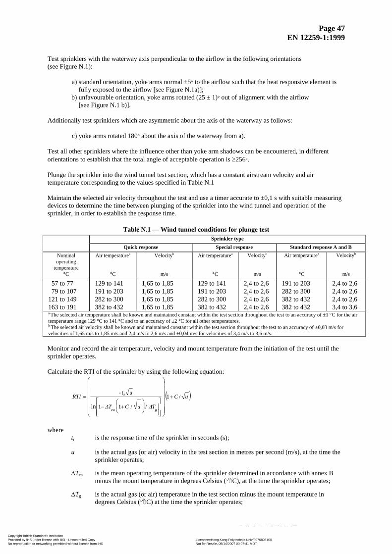
Page 47 EN 12259-1:1999
Test sprinklers with the waterway axis perpendicular to the airflow in the following orientations (see Figure N.1):
a) standard orientation, yoke arms normal ±5° to the airflow such that the heat responsive element is fully exposed to the airflow [see Figure N.1a)];
b) unfavourable orientation, yoke arms rotated (25 ± 1)° out of alignment with the airflow [see Figure N.1 b)].
Additionally test sprinklers which are asymmetric about the axis of the waterway as follows:
c) yoke arms rotated 180° about the axis of the waterway from a). Test all other sprinklers where the influence other than yoke arm shadows can be encountered, in different orientations to establish that the total angle of acceptable operation is ≥256°. Plunge the sprinkler into the wind tunnel test section, which has a constant airstream velocity and air temperature corresponding to the values specified in Table N.1 Maintain the selected air velocity throughout the test and use a timer accurate to ±0,1 s with suitable measuring devices to determine the time between plunging of the sprinkler into the wind tunnel and operation of the sprinkler, in order to establish the response time.
Table N.1 — Wind tunnel conditions for plunge test Sprinkler type Quick response Special response Standard response A and B
Nominal operating
temperature
Air temperaturea Velocityb Air temperaturea Velocityb Air temperaturea Velocityb
°C °C m/s °C m/s °C m/s
57 to 77 129 to 141 1,65 to 1,85 129 to 141 2,4 to 2,6 191 to 203 2,4 to 2,6 79 to 107 191 to 203 1,65 to 1,85 191 to 203 2,4 to 2,6 282 to 300 2,4 to 2,6 121 to 149 282 to 300 1,65 to 1,85 282 to 300 2,4 to 2,6 382 to 432 2,4 to 2,6 163 to 191 382 to 432 1,65 to 1,85 382 to 432 2,4 to 2,6 382 to 432 3,4 to 3,6 a The selected air temperature shall be known and maintained constant within the test section throughout the test to an accuracy of ±1 °C for the air temperature range 129 °C to 141 °C and to an accuracy of ±2 °C for all other temperatures. b The selected air velocity shall be known and maintained constant within the test section throughout the test to an accuracy of ±0,03 m/s for velocities of 1,65 m/s to 1,85 m/s and 2,4 m/s to 2,6 m/s and ±0,04 m/s for velocities of 3,4 m/s to 3,6 m/s. Monitor and record the air temperature, velocity and mount temperature from the initiation of the test until the sprinkler operates. Calculate the RTI of the sprinkler by using the following equation:
( )uC
TuCT
utRTI
gea
/1
//11
-
ln
r +
+−⎟⎟⎟⎟⎟⎟
⎠
⎞
⎜⎜⎜⎜⎜⎜
⎝
⎛
⎥⎥⎦
⎤
⎢⎢⎣
⎡⎟⎠⎞
⎜⎝⎛
=
ΔΔ
where
tr is the response time of the sprinkler in seconds (s); u is the actual gas (or air) velocity in the test section in metres per second (m/s), at the time the
sprinkler operates; ΔTea is the mean operating temperature of the sprinkler determined in accordance with annex B
minus the mount temperature in degrees Celsius ( C), at the time the sprinkler operates; ΔTg is the actual gas (or air) temperature in the test section minus the mount temperature in
degrees Celsius ( C) at the time the sprinkler operates;
Copyright British Standards Institution Provided by IHS under license with BSI - Uncontrolled Copy Licensee=Hong Kong Polytechnic Univ/9976803100
Not for Resale, 05/14/2007 00:07:41 MDTNo reproduction or networking permitted without license from IHS
--`,`,`,,``,,`,```,,,``,``,,``-`-`,,`,,`,`,,`---
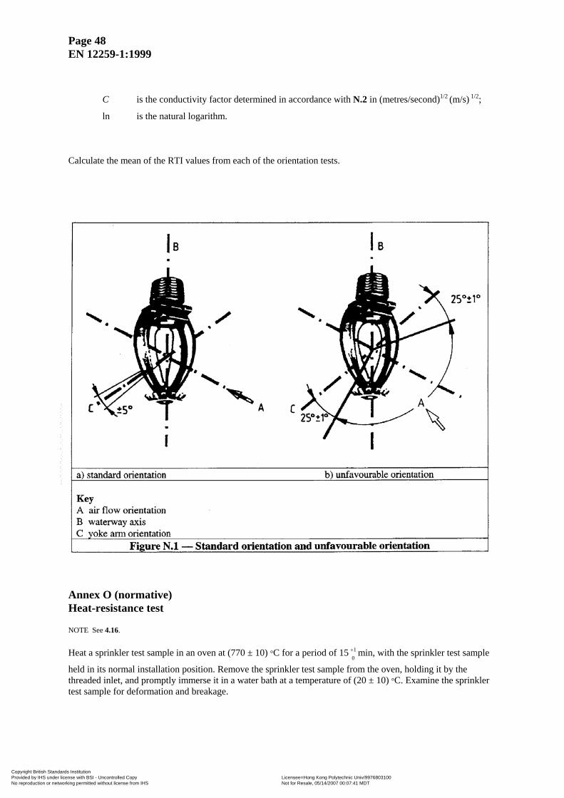
Page 48 EN 12259-1:1999
C
is the conductivity factor determined in accordance with N.2 in (metres/second)1/2 (m/s) 1/2;
ln is the natural logarithm. Calculate the mean of the RTI values from each of the orientation tests.
Annex O (normative) Heat-resistance test NOTE See 4.16. Heat a sprinkler test sample in an oven at (770 ± 10) °C for a period of 15 min, with the sprinkler test sample
held in its normal installation position. Remove the sprinkler test sample from the oven, holding it by the threaded inlet, and promptly immerse it in a water bath at a temperature of (20 ± 10) °C. Examine the sprinkler test sample for deformation and breakage.
01+
Copyright British Standards Institution Provided by IHS under license with BSI - Uncontrolled Copy Licensee=Hong Kong Polytechnic Univ/9976803100
Not for Resale, 05/14/2007 00:07:41 MDTNo reproduction or networking permitted without license from IHS
--`,`,`,,``,,`,```,,,``,``,,``-`-`,,`,,`,`,,`---
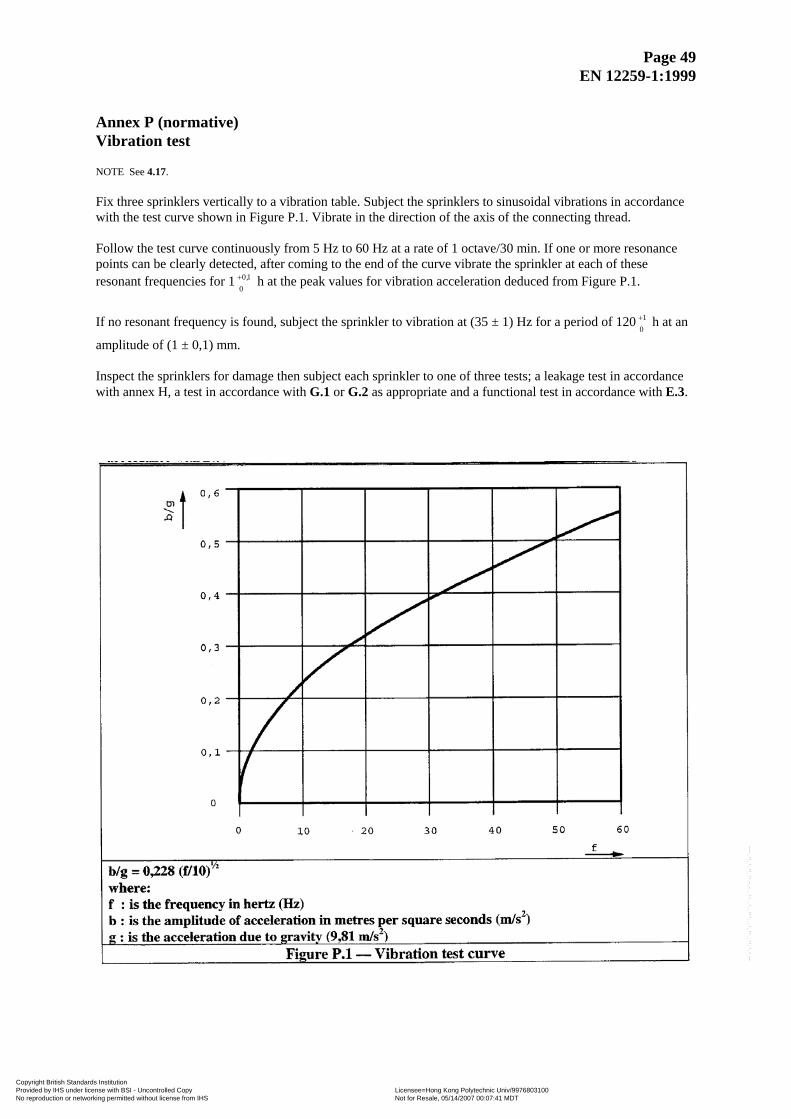
Page 49 EN 12259-1:1999
Annex P (normative) Vibration test NOTE See 4.17. Fix three sprinklers vertically to a vibration table. Subject the sprinklers to sinusoidal vibrations in accordance with the test curve shown in Figure P.1. Vibrate in the direction of the axis of the connecting thread. Follow the test curve continuously from 5 Hz to 60 Hz at a rate of 1 octave/30 min. If one or more resonance points can be clearly detected, after coming to the end of the curve vibrate the sprinkler at each of these resonant frequencies for 1 h at the peak values for vibration acceleration deduced from Figure P.1.
010,+
If no resonant frequency is found, subject the sprinkler to vibration at (35 ± 1) Hz for a period of 120 h at an
amplitude of (1 ± 0,1) mm. 01+
Inspect the sprinklers for damage then subject each sprinkler to one of three tests; a leakage test in accordance with annex H, a test in accordance with G.1 or G.2 as appropriate and a functional test in accordance with E.3.
Copyright British Standards Institution Provided by IHS under license with BSI - Uncontrolled Copy Licensee=Hong Kong Polytechnic Univ/9976803100
Not for Resale, 05/14/2007 00:07:41 MDTNo reproduction or networking permitted without license from IHS
--`,`,`,,``,,`,```,,,``,``,,``-`-`,,`,,`,`,,`---
Page 50 EN 12259-1:1999
Annex Q (normative) Impact test NOTE See 4.18. Test five sprinklers by dropping a weight on to the deflector of the sprinkler along the axial centre line of the waterway. The kinetic energy of the dropped weight at the point of impact shall be equivalent to that of a weight of the same mass as the test sprinkler dropped from the height of 1 m. Prevent the weight from impacting more than once upon each sample. Test for leakage in accordance with annex H and functional test in accordance with E.3. Annex R (normative) Resistance to low temperature test NOTE See 4.19. Subject four sprinklers to a temperature of (-20 ± 2) °C for a period of 24 h. Then allow the sprinklers to
stand for at least 2 h at room temperature. Examine the sprinklers and subject them to a functional test in accordance with E.3.
01+
Copyright British Standards Institution Provided by IHS under license with BSI - Uncontrolled Copy Licensee=Hong Kong Polytechnic Univ/9976803100
Not for Resale, 05/14/2007 00:07:41 MDTNo reproduction or networking permitted without license from IHS
--`,`,`,,``,,`,```,,,``,``,,``-`-`,,`,,`,`,,`---
Page 51 EN 12259-1:1999
Annex S (informative) Notes on strength test for fusible link release elements NOTE See 4.8.2 and G.2. The formula given in G.2 is based on the intention of providing fusible elements that are not susceptible to creep stress failure during a reasonable period of service. The duration of 876 600 h (100 years) was selected only as a statistical value with an ample safety factor. No other significance is intended, as many other factors govern the useful life of a sprinkler. Loads causing failure by creep, and not by an unnecessarily high initial distortion stress, are applied and the times to failure noted. The given requirement then approximates to the extrapolation of the logarithmic regression curve by means of the following analysis: The observed data is used to determine, by means of the method of least squares, the load causing failure at 1 h, Lo, and the load causing failure at 1 000 h, Lm. One way of stating this is that, when plotted on log paper, the slope of the line determined by Lm and Lo shall be greater than or equal to the slope determined by the design load at 100 years, Ld, and Lo; or
600876 lnlnln
0001lnlnln odom L- L
L - L ≥
This is reduced as follows:
( ) oodm ln000876ln
0001lnlnlnln LLLL +−≥
≥ 0,5048 (ln Ld - ln Lo) + ln Lo ≥ 0,5048 [ln Ld + (1 - 0,5048) ln Lo] ≥ 0,5048 ln Ld + 0,4952 ln Lo
With an error of approximately 1 %, the formula may be approximated by
ln Lm ≥ 0,5 (ln Ld + ln Lo) or, compensating for errors
L L L odm 0,99 ×≥
o
m2
d 02,1LLL ≥
Copyright British Standards Institution Provided by IHS under license with BSI - Uncontrolled Copy Licensee=Hong Kong Polytechnic Univ/9976803100
Not for Resale, 05/14/2007 00:07:41 MDTNo reproduction or networking permitted without license from IHS
--`,`,`,,``,,`,```,,,``,``,,``-`-`,,`,,`,`,,`---
Page 52 EN 12259-1:1999
Annex ZA (informative) Clauses of this European Standard addressing the provisions of the EU Construction Products Directive ZA.1 Clauses of this European Standard addressing essential requirements or other provisions of EU Construction Products Directive This European Standard has been prepared under the Mandate given to CEN by the European Commission and the European Free Trade Association. The clauses of this European Standard, shown in this annex, meet the requirements of the Mandate given under the EU Construction Products Directive (89/106/EEC). Compliance with these clauses confers the presumption of fitness of the construction products covered by this European Standard for their intended use.
WARNING Other requirements and EU directives, not affecting the fitness for intended use may be applicable to a construction product falling within the scope of this standard.
NOTE: In addition to any specific clauses relating to dangerous substances contained in this standard, there may be other requirements applicable to the products falling within its scope (e.g. transposed European legislation and national laws, regulations and administrative provisions). In order to meet the provisions of the EU Construction Product Directive, these requirements need also to be complied with, when and where they apply. An informative database of European and national provisions on dangerous substances is available at the Construction web site on EUROPA (CREATE, accessed through http://europa.eu.int). Construction product: Sprinkler Intended use(s): Sprinklers for fire control/suppression in land based buildings and structures.
Copyright British Standards Institution Provided by IHS under license with BSI - Uncontrolled Copy Licensee=Hong Kong Polytechnic Univ/9976803100
Not for Resale, 05/14/2007 00:07:41 MDTNo reproduction or networking permitted without license from IHS
--`,`,`,,``,,`,```,,,``,``,,``-`-`,,`,,`,`,,`---
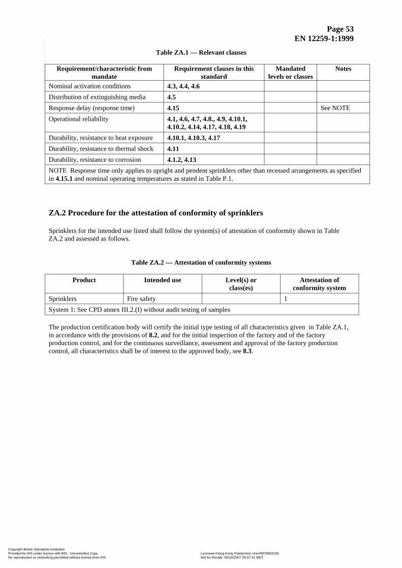
Page 53 EN 12259-1:1999
Table ZA.1 — Relevant clauses
Requirement/characteristic from mandate
Requirement clauses in this standard
Mandated levels or classes
Notes
Nominal activation conditions 4.3, 4.4, 4.6 Distribution of extinguishing media 4.5 Response delay (response time) 4.15 See NOTE Operational reliability 4.1, 4.6, 4.7, 4.8., 4.9, 4.10.1,
4.10.2, 4.14, 4.17, 4.18, 4.19
Durability, resistance to heat exposure 4.10.1, 4.10.3, 4.17 Durability, resistance to thermal shock 4.11 Durability, resistance to corrosion 4.1.2, 4.13 NOTE Response time only applies to upright and pendent sprinklers other than recessed arrangements as specified in 4.15.1 and nominal operating temperatures as stated in Table P.1. ZA.2 Procedure for the attestation of conformity of sprinklers Sprinklers for the intended use listed shall follow the system(s) of attestation of conformity shown in Table ZA.2 and assessed as follows.
Table ZA.2 — Attestation of conformity systems
Product Intended use Level(s) or class(es)
Attestation of conformity system
Sprinklers Fire safety 1 System 1: See CPD annex III.2.(I) without audit testing of samples The production certification body will certify the initial type testing of all characteristics given in Table ZA.1, in accordance with the provisions of 8.2, and for the initial inspection of the factory and of the factory production control, and for the continuous surveillance, assessment and approval of the factory production control, all characteristics shall be of interest to the approved body, see 8.3.
Copyright British Standards Institution Provided by IHS under license with BSI - Uncontrolled Copy Licensee=Hong Kong Polytechnic Univ/9976803100
Not for Resale, 05/14/2007 00:07:41 MDTNo reproduction or networking permitted without license from IHS
--`,`,`,,``,,`,```,,,``,``,,``-`-`,,`,,`,`,,`---
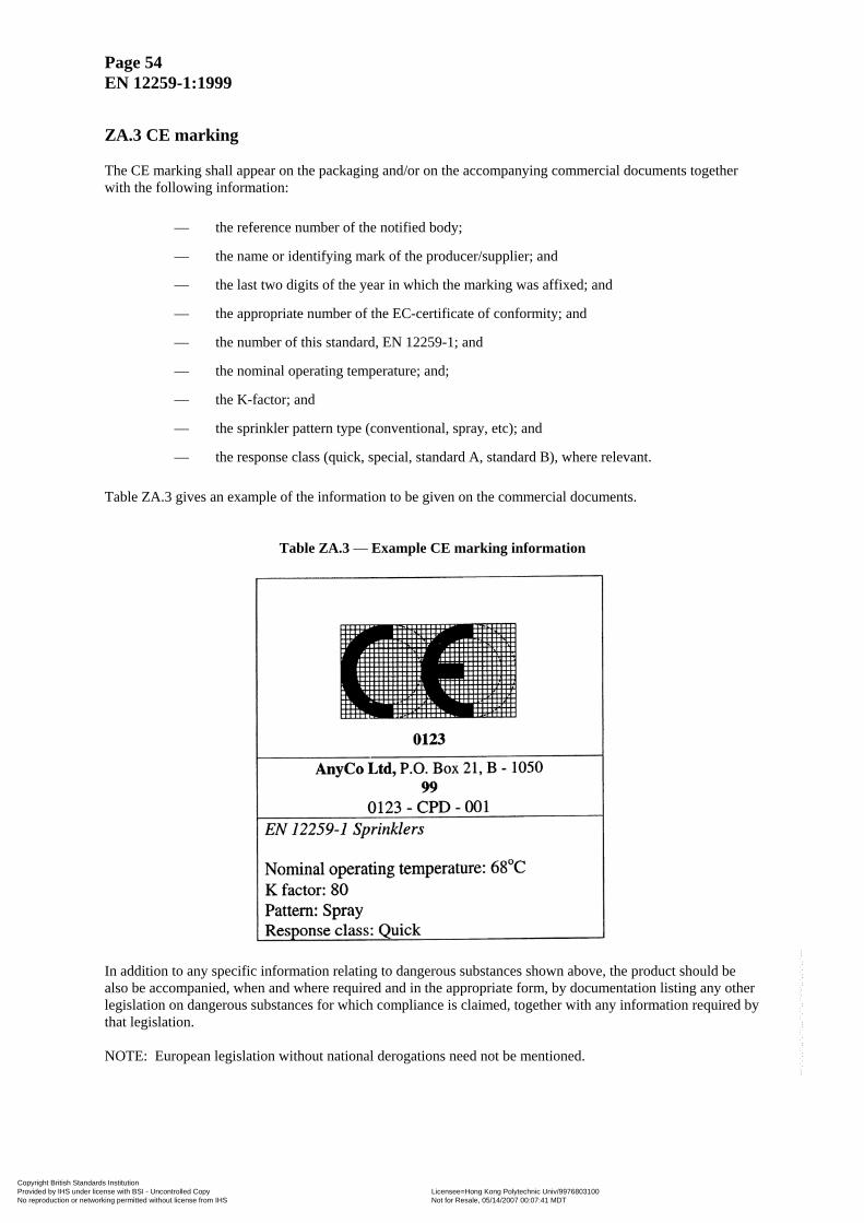
Page 54 EN 12259-1:1999
ZA.3 CE marking The CE marking shall appear on the packaging and/or on the accompanying commercial documents together with the following information:
— the reference number of the notified body;
— the name or identifying mark of the producer/supplier; and
— the last two digits of the year in which the marking was affixed; and
— the appropriate number of the EC-certificate of conformity; and
— the number of this standard, EN 12259-1; and
— the nominal operating temperature; and;
— the K-factor; and
— the sprinkler pattern type (conventional, spray, etc); and
— the response class (quick, special, standard A, standard B), where relevant. Table ZA.3 gives an example of the information to be given on the commercial documents.
Table ZA.3 — Example CE marking information
In addition to any specific information relating to dangerous substances shown above, the product should be also be accompanied, when and where required and in the appropriate form, by documentation listing any other legislation on dangerous substances for which compliance is claimed, together with any information required by that legislation. NOTE: European legislation without national derogations need not be mentioned.
Copyright British Standards Institution Provided by IHS under license with BSI - Uncontrolled Copy Licensee=Hong Kong Polytechnic Univ/9976803100
Not for Resale, 05/14/2007 00:07:41 MDTNo reproduction or networking permitted without license from IHS
--`,`,`,,``,,`,```,,,``,``,,``-`-`,,`,,`,`,,`---

Page 55 EN 12259-1:1999
ZA.4 EC Certificate and Declaration of Conformity The manufacturer or his agent established in the EEA, shall prepare and retain a declaration of conformity, which authorizes the affixing of the CE marking. This declaration shall include:
— name and address of the manufacturer, or his authorized representative established in the EEA, and the place of production;
— description of the product (type, identification, use), and a copy of the information accompanying the CE marking;
— provisions to which the product conforms (e.g. annex ZA of this European Standard);
— particular conditions applicable to the use of the product (if necessary);
— name and address (or identification number) of the approved body(bodies);
— name of, and position held by, the empowered to sign the declaration on behalf of the manufacturer or of his authorized representative.
For characteristics where certification is required (system 1), the declaration shall contain a certificate of conformity with, in addition to the information above, the following information:
— the name and address of the certification body; — the certificate number; — conditions and period of validity of the certificate, where applicable; — name of, and position held by, the empowered to sign the certificate.
Duplication of information between the declaration and certificate shall be avoided. The declaration and certificate shall be presented in the language(s) of the Member State of use of the product.
Copyright British Standards Institution Provided by IHS under license with BSI - Uncontrolled Copy Licensee=Hong Kong Polytechnic Univ/9976803100
Not for Resale, 05/14/2007 00:07:41 MDTNo reproduction or networking permitted without license from IHS
--`,`,`,,``,,`,```,,,``,``,,``-`-`,,`,,`,`,,`---
Page 56 EN 12259-1:1999
Bibliography EN ISO 9001 Quality management systems Requirements (ISO 9001:2000) Information on thermal response
NOTE See 4.15 and N The plunge test and the prolonged exposure ramp test are described in the following publications: a) Heskestad, G. and Bill, R.G.,Jr., Conduction heat loss effects on thermal response of
automatic sprinklers, Factory Mutual Research Corporation, September 1987.
b) Heskestad, G. and Smith, H.F., Plunge test for determination of sprinkler sensitivity, Factory Mutual Research Corporation, December 1980.
c) Heskestad, G. and Smith, H.F., Investigation of a new sprinkler sensitivity approval test: The plunge test, Factory Mutual Research Corporation, December 1973.
d) ISO/TC 21/SC 5/WG 1 document N 157, VdS, Cologne, 1988.
e) ISO/TC 21/SC 5/WG1 document N186, Job GmbH, September 1990.
Copyright British Standards Institution Provided by IHS under license with BSI - Uncontrolled Copy Licensee=Hong Kong Polytechnic Univ/9976803100
Not for Resale, 05/14/2007 00:07:41 MDTNo reproduction or networking permitted without license from IHS
--`,`,`,,``,,`,```,,,``,``,,``-`-`,,`,,`,`,,`---

blankCopyright British Standards Institution Provided by IHS under license with BSI - Uncontrolled Copy Licensee=Hong Kong Polytechnic Univ/9976803100
Not for Resale, 05/14/2007 00:07:41 MDTNo reproduction or networking permitted without license from IHS
--`,`,`,,``,,`,```,,,``,``,,``-`-`,,`,,`,`,,`---
CopProNo
BS EN 12259-1:1999
vr
--`,`,`,,``,,`,```,,,``,``,,``-`-`,,`,,`,`,,`---
BSI
389 Chiswick High Road
London
W4 4AL
yright British Standards Institution ided by IHS under license with BSI - Uncontrolled Copy eproduction or networking permitted without license from IHS
BSI — British Standards InstitutionBSI is the independent national body responsible for preparing British Standards. It presents the UK view on standards in Europe and at the international level. It is incorporated by Royal Charter.
Revisions
British Standards are updated by amendment or revision. Users of British Standards should make sure that they possess the latest amendments or editions.
It is the constant aim of BSI to improve the quality of our products and services. We would be grateful if anyone finding an inaccuracy or ambiguity while using this British Standard would inform the Secretary of the technical committee responsible, the identity of which can be found on the inside front cover. Tel: +44 (0)20 8996 9000. Fax: +44 (0)20 8996 7400.
BSI offers members an individual updating service called PLUS which ensures that subscribers automatically receive the latest editions of standards.
Buying standards
Orders for all BSI, international and foreign standards publications should be addressed to Customer Services. Tel: +44 (0)20 8996 9001. Fax: +44 (0)20 8996 7001. Email: [email protected]. Standards are also available from the BSI website at http://www.bsi-global.com.
In response to orders for international standards, it is BSI policy to supply the BSI implementation of those that have been published as British Standards, unless otherwise requested.
Information on standards
BSI provides a wide range of information on national, European and international standards through its Library and its Technical Help to Exporters Service. Various BSI electronic information services are also available which give details on all its products and services. Contact the Information Centre. Tel: +44 (0)20 8996 7111. Fax: +44 (0)20 8996 7048. Email: [email protected].
Subscribing members of BSI are kept up to date with standards developments and receive substantial discounts on the purchase price of standards. For details of these and other benefits contact Membership Administration. Tel: +44 (0)20 8996 7002. Fax: +44 (0)20 8996 7001. Email: [email protected].
Information regarding online access to British Standards via British Standards Online can be found at http://www.bsi-global.com/bsonline.
Further information about BSI is available on the BSI website at http://www.bsi-global.com.
Copyright
Copyright subsists in all BSI publications. BSI also holds the copyright, in the UK, of the publications of the international standardization bodies. Except as permitted under the Copyright, Designs and Patents Act 1988 no extract may be reproduced, stored in a retrieval system or transmitted in any form or by any means – electronic, photocopying, recording or otherwise – without prior written permission from BSI.
This does not preclude the free use, in the course of implementing the standard, of necessary details such as symbols, and size, type or grade designations. If these details are to be used for any other purpose than implementation then the prior written permission of BSI must be obtained.
Details and advice can be obtained from the Copyright & Licensing Manager. Tel: +44 (0)20 8996 7070. Fax: +44 (0)20 8996 7553. Email: [email protected].
Licensee=Hong Kong Polytechnic Univ/9976803100 Not for Resale, 05/14/2007 00:07:41 MDT