Embed Size (px)
Citation preview
LOW-COST MEDICAL WASTEINCINERATOR
Manufacturing, Operation and Maintenance InstructionsDate of issue: 27 May, 2002
Contents:
1 Introduction Page 2
2 Construction Page 3
3 Operation Page 13
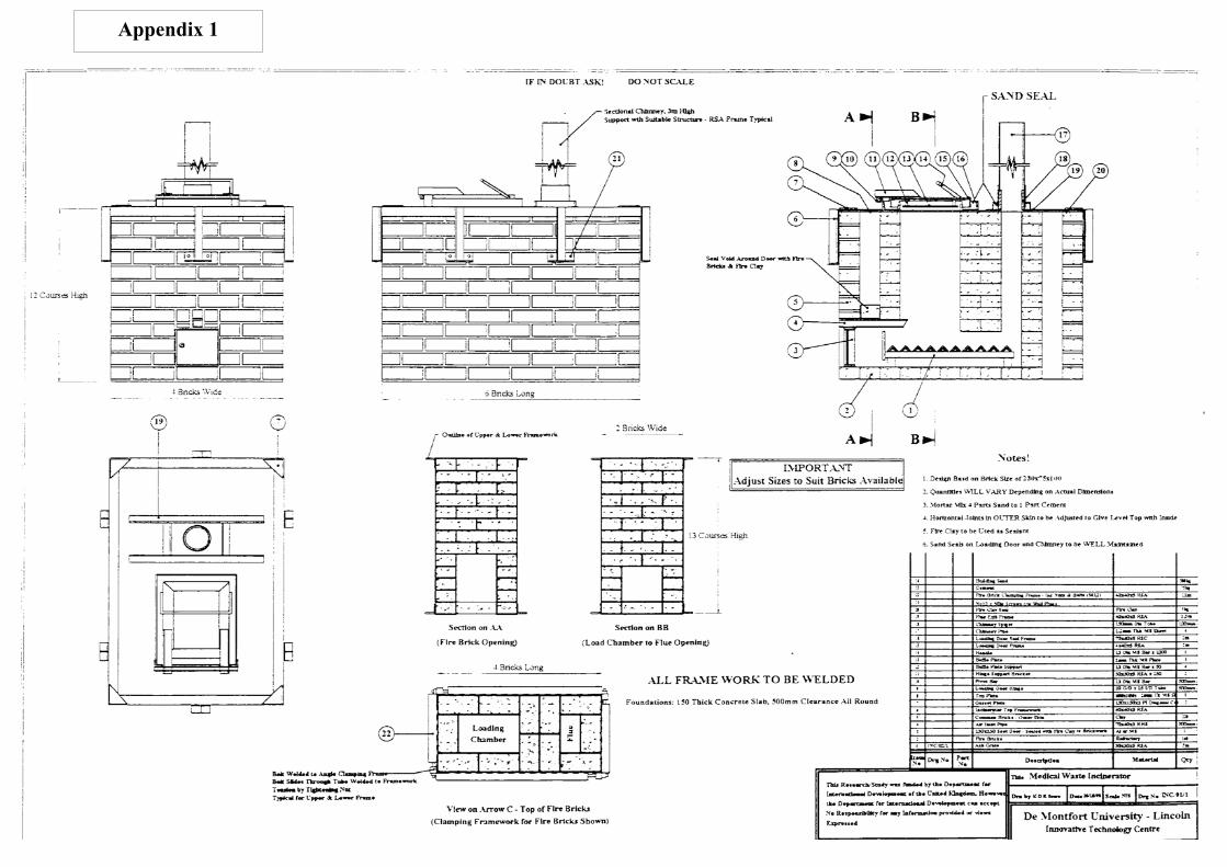
4 Main construction drawing Centre pages
5 Appendix II – materials list Page 18
The incinerator described was developed by the Innovative Technology Group atDe Montfort University under the direction of Professor D J Picken.
The text and photographs used in the preparation of this Technical Brief were provided byAndrew Russell, consultant in energy and appropriate technology and Project Engineer for thisproject..
Bourton Hall, Bourt
Intermediate
Tech
nica
l Not
e
Information Services, The Schumacher Centre for Technology and Development,on-on-Dunsmore, Rugby, Warwickshire CV23 9QZ. Tel: +44 (0)1788 661100 Fax: +44 (0)1788 661101
Email: [email protected] Technology Development Group Ltd., Company Reg No. 871954, England, Charity No. 247257.
2
2
1 Introduction
The medical waste incinerator is a simple two-chamber natural-draught incineratordesigned to be operated at temperatures of 800oC and higher. The performance of theincinerator will vary depending on the moisture content of the medical waste but athroughput of up to 15kg/hour can be achieved. The incinerator has been designed sothat it can be built on site, using standard building bricks or blocks and lined withrefractory bricks. All the steel components, such as the loading door, the ash removaldoor and air inlet apertures can be made using basic workshop equipment.
Wood, wood and dry waste soaked in kerosene or diesel is required initially to start thecombustion process. Once the correct temperature is reached, the medical waste isloaded into the incinerator. Much of the medical waste will have value as a fuel andwill contribute towards combustion but additional wood or kerosene may be required toensure that adequate combustion temperatures are maintained.
The initial combustion occurs in the primary chamber and then the hot gases pass intothe secondary chamber where the combustion process is completed. The two-chamberdesign helps to ensure that the combustion time is sufficient to destroy the products ofcombustion and minimise any harmful emissions.
The incinerator should be situated under a simple open-sided roofed structure, such as alean-to, away from tall buildings and in an area free from air turbulence. Although itcan be operated in the open, a roof will help to protect the incinerator from rain andprovides shelter for the operator.
The incinerator is capable of incinerating most types of medical waste includingtextiles, plastics and packaging. It can also incinerate most types of drugs, medicines,vaccines and sharps – as long as they are mixed with other wastes. However, as grease-based products, such as ointments, creams and Vaseline create large quantities of denseblack smoke when burned , they are best disposed of by other means.
3
3
Definitions
The fuel value is the ability of any material to contribute to sustained combustion. Amaterial with a high fuel value will contribute to the combustion process helping tomaintain high temperatures. Materials with a low fuel value will result in poorcombustion and may, depending on the amount of other high value fuel available inthe incinerator, lower the combustion temperatures or even cause combustion tocease.Stack is another name for a chimney. Support fuel is the fuel used to start the incinerator and, when necessary, to provideadditional combustible material to ensure effective incineration. Refractory bricks (firebricks) are made from refractory clay which can withstandhigh temperatures. Depending on the manufacturer, they can be available in a rangeof sizes and grades.
2 CONSTRUCTION
2.1 Introduction
The following construction notes should be used in conjunction with the maindrawing of the incinerator (see appendix 1). These notes are based on experiencegained during the design and development of the prototype in the UK and thebuilding and operating of incinerators at four hospitals in developing countries. Twoof these incinerators are located in Nepal (one using either wood or kerosene and theother kerosene only), one is in Zimbabwe (using wood) and one in South Africa(using diesel).
Although these notes describe proven techniques for the successful construction ofthe incinerator, it should not be assumed that this is the only way of building one.Minor modifications to material sizes, types or specification may be required to suitlocal conditions. With the exception of the refractory bricks, all the other materialsspecified in the materials list (see appendix 2) could be replaced with others ofdifferent sizes or specification to suit local availability. For instance, the commonbuilding bricks used for the outer wall could be replaced with cement bricks (as inZimbabwe) or blocks, or where an angle iron of 50 x 50 x 3 is specified, 40 x 40 x 3could be used instead.
The actual size of the incinerator is dependent on the size of the bricks used andbecause the standard size of brick can be different from country to country – andeven from region to region - slight differences in size of the incinerator may beexpected. These variations should not effect the performance of the incinerator.
4
4
2.2 General description of construction
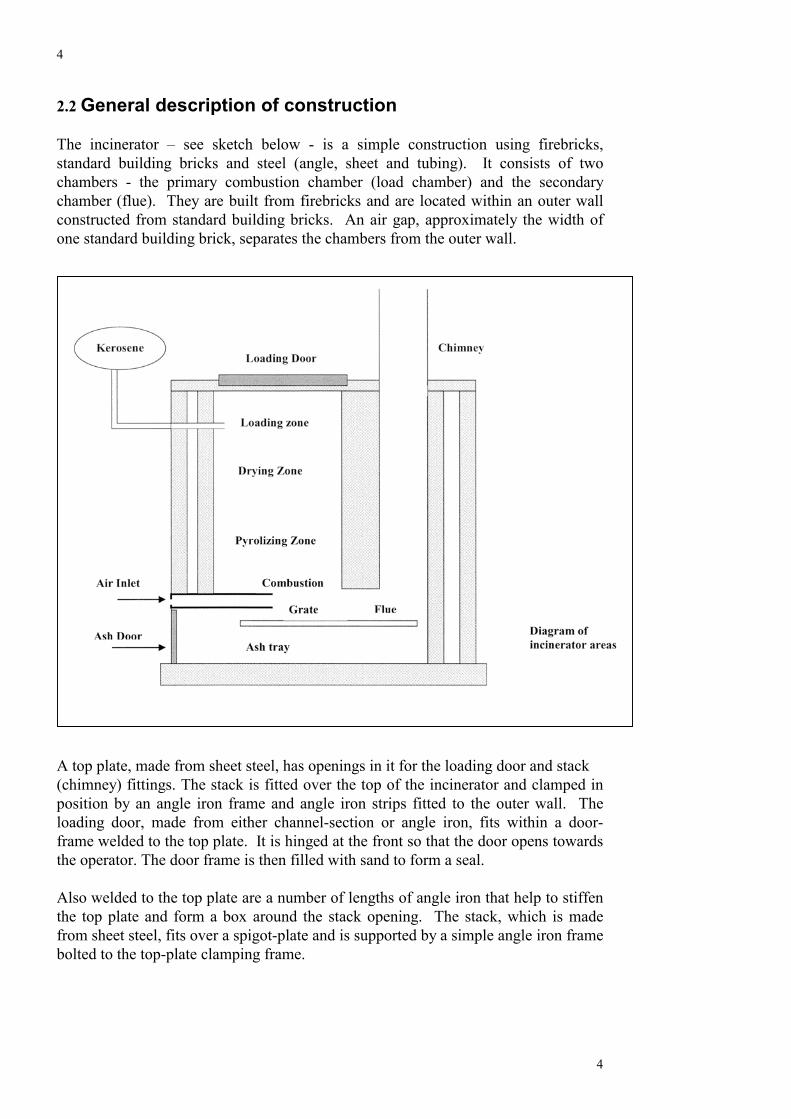
The incinerator – see sketch below - is a simple construction using firebricks,standard building bricks and steel (angle, sheet and tubing). It consists of twochambers - the primary combustion chamber (load chamber) and the secondarychamber (flue). They are built from firebricks and are located within an outer wallconstructed from standard building bricks. An air gap, approximately the width ofone standard building brick, separates the chambers from the outer wall.
A top plate, made from sheet steel, has openings in it for the loading door and stack (chimney) fittings. The stack is fitted over the top of the incinerator and clamped inposition by an angle iron frame and angle iron strips fitted to the outer wall. Theloading door, made from either channel-section or angle iron, fits within a door-frame welded to the top plate. It is hinged at the front so that the door opens towardsthe operator. The door frame is then filled with sand to form a seal.
Also welded to the top plate are a number of lengths of angle iron that help to stiffenthe top plate and form a box around the stack opening. The stack, which is madefrom sheet steel, fits over a spigot-plate and is supported by a simple angle iron framebolted to the top-plate clamping frame.
5
5
2.3 Guidance notes
Foundation
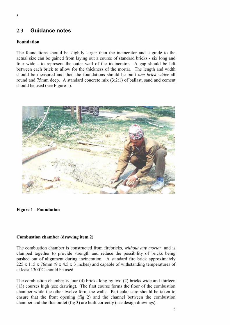
The foundations should be slightly larger than the incinerator and a guide to theactual size can be gained from laying out a course of standard bricks - six long andfour wide - to represent the outer wall of the incinerator. A gap should be leftbetween each brick to allow for the thickness of the mortar. The length and widthshould be measured and then the foundations should be built one brick wider allround and 75mm deep. A standard concrete mix (3:2:1) of ballast, sand and cementshould be used (see Figure 1).
Figure 1 - Foundation
Combustion chamber (drawing item 2)
The combustion chamber is constructed from firebricks, without any mortar, and isclamped together to provide strength and reduce the possibility of bricks beingpushed out of alignment during incineration. A standard fire brick approximately225 x 115 x 76mm (9 x 4.5 x 3 inches) and capable of withstanding temperatures ofat least 1300oC should be used.
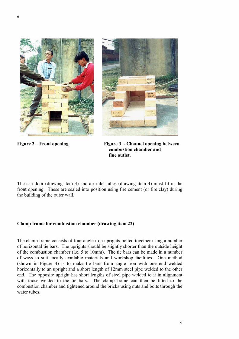
The combustion chamber is four (4) bricks long by two (2) bricks wide and thirteen(13) courses high (see drawing). The first course forms the floor of the combustionchamber while the other twelve form the walls. Particular care should be taken toensure that the front opening (fig 2) and the channel between the combustionchamber and the flue outlet (fig 3) are built correctly (see design drawings).
6
6
Figure 2 – Front opening Figure 3 - Channel opening between combustion chamber and flue outlet.
The ash door (drawing item 3) and air inlet tubes (drawing item 4) must fit in thefront opening. These are sealed into position using fire cement (or fire clay) duringthe building of the outer wall.
Clamp frame for combustion chamber (drawing item 22)
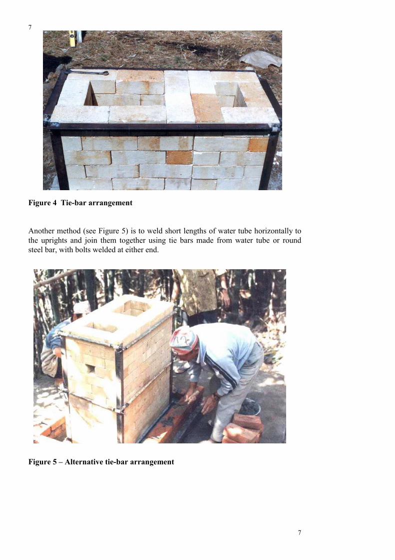
The clamp frame consists of four angle iron uprights bolted together using a numberof horizontal tie bars. The uprights should be slightly shorter than the outside heightof the combustion chamber (i.e. 5 to 10mm). The tie bars can be made in a numberof ways to suit locally available materials and workshop facilities. One method(shown in Figure 4) is to make tie bars from angle iron with one end weldedhorizontally to an upright and a short length of 12mm steel pipe welded to the otherend. The opposite upright has short lengths of steel pipe welded to it in alignmentwith those welded to the tie bars. The clamp frame can then be fitted to thecombustion chamber and tightened around the bricks using nuts and bolts through thewater tubes.
7
7
Figure 4 Tie-bar arrangement
Another method (see Figure 5) is to weld short lengths of water tube horizontally tothe uprights and join them together using tie bars made from water tube or roundsteel bar, with bolts welded at either end.
Figure 5 – Alternative tie-bar arrangement
8
8
Air inlets (drawing item 4)
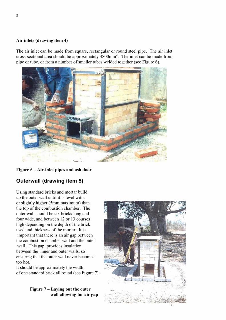
The air inlet can be made from square, rectangular or round steel pipe. The air inletcross-sectional area should be approximately 4800mm2. The inlet can be made frompipe or tube, or from a number of smaller tubes welded together (see Figure 6).
Figure 6 – Air-inlet pipes and ash door
Outerwall (drawing item 5)
Using standard bricks and mortar build up the outer wall until it is level with,or slightly higher (5mm maximum) than the top of the combustion chamber. The outer wall should be six bricks long andfour wide, and between 12 or 13 courses high depending on the depth of the brickused and thickness of the mortar. It is important that there is an air gap between the combustion chamber wall and the outer wall. This gap provides insulation between the inner and outer walls, soensuring that the outer wall never becomes too hot. It should be approximately the width of one standard brick all round (see Figure 7).
Figure 7 – Laying out the outer
wall allowing for air gap
9
While building up the outer wall, the ash door and air inlet tubes should be fitted.Where they pass into the combustion chamber they should be fixed in position usingfire cement. Where they are located in the outer wall, the ash door and air tubesshould be fixed using ordinary mortar.
The air tubes should be long enough to be flush with the brick work in the outer walland should only protrude slightly into the combustion chamber.
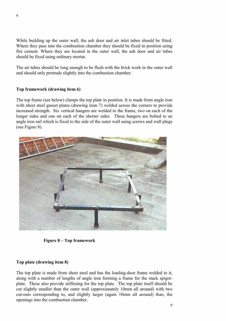
Top framework (drawing item 6)
The top frame (see below) clamps the top plate in position. It is made from angle ironwith sheet steel gusset plates (drawing item 7) welded across the corners to provideincreased strength. Six vertical hangers are welded to the frame, two on each of thelonger sides and one on each of the shorter sides. These hangers are bolted to anangle iron rail which is fixed to the side of the outer wall using screws and wall plugs(see Figure 8).
T
Tapcco
9
Figure 8 – Top framework
op plate (drawing item 8)
he top plate is made from sheet steel and has the loading-door frame welded to it,long with a number of lengths of angle iron forming a frame for the stack spigot-late. These also provide stiffening for the top plate. The top plate itself should beut slightly smaller than the outer wall (approximately 10mm all around) with twout-outs corresponding to, and slightly larger (again 10mm all around) than, thepenings into the combustion chamber.
10
10
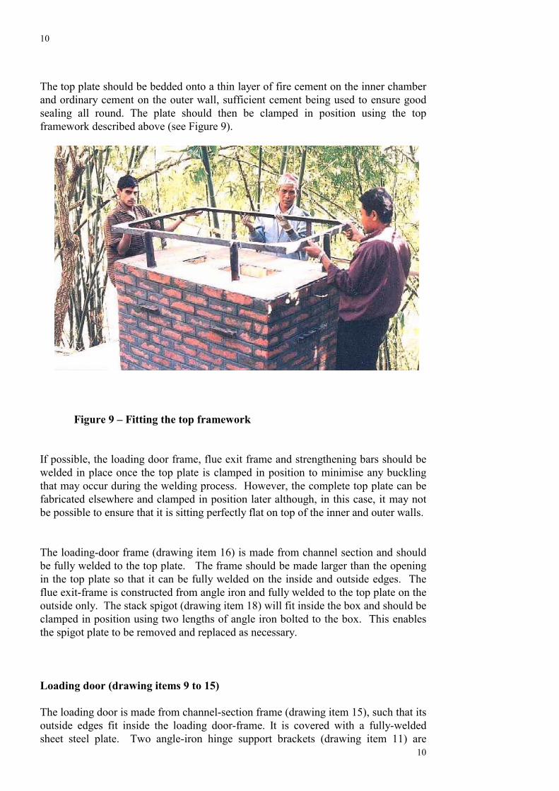
The top plate should be bedded onto a thin layer of fire cement on the inner chamberand ordinary cement on the outer wall, sufficient cement being used to ensure goodsealing all round. The plate should then be clamped in position using the topframework described above (see Figure 9).
Figure 9 – Fitting the top framework
If possible, the loading door frame, flue exit frame and strengthening bars should bewelded in place once the top plate is clamped in position to minimise any bucklingthat may occur during the welding process. However, the complete top plate can befabricated elsewhere and clamped in position later although, in this case, it may notbe possible to ensure that it is sitting perfectly flat on top of the inner and outer walls.
The loading-door frame (drawing item 16) is made from channel section and shouldbe fully welded to the top plate. The frame should be made larger than the openingin the top plate so that it can be fully welded on the inside and outside edges. Theflue exit-frame is constructed from angle iron and fully welded to the top plate on theoutside only. The stack spigot (drawing item 18) will fit inside the box and should beclamped in position using two lengths of angle iron bolted to the box. This enablesthe spigot plate to be removed and replaced as necessary.
Loading door (drawing items 9 to 15)
The loading door is made from channel-section frame (drawing item 15), such that itsoutside edges fit inside the loading door-frame. It is covered with a fully-weldedsheet steel plate. Two angle-iron hinge support brackets (drawing item 11) are
11
11
welded on top of the door. A baffle plate (drawing item 13) is suspended beneath thedoor so that it hangs into the combustion chamber by approximately 100mm whenthe door is closed. This baffle plate will help prevent the door and door handlebecoming too hot during operation. The sheet steel cover should be welded inposition on top of the door.
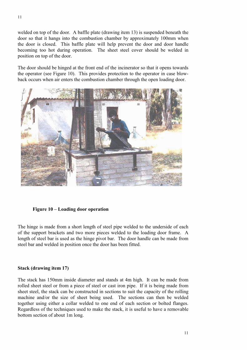
The door should be hinged at the front end of the incinerator so that it opens towardsthe operator (see Figure 10). This provides protection to the operator in case blow-back occurs when air enters the combustion chamber through the open loading door.
Figure 10 – Loading door operation
The hinge is made from a short length of steel pipe welded to the underside of eachof the support brackets and two more pieces welded to the loading door frame. Alength of steel bar is used as the hinge pivot bar. The door handle can be made fromsteel bar and welded in position once the door has been fitted.
Stack (drawing item 17)
The stack has 150mm inside diameter and stands at 4m high. It can be made fromrolled sheet steel or from a piece of steel or cast iron pipe. If it is being made fromsheet steel, the stack can be constructed in sections to suit the capacity of the rollingmachine and/or the size of sheet being used. The sections can then be weldedtogether using either a collar welded to one end of each section or bolted flanges.Regardless of the techniques used to make the stack, it is useful to have a removablebottom section of about 1m long.
12
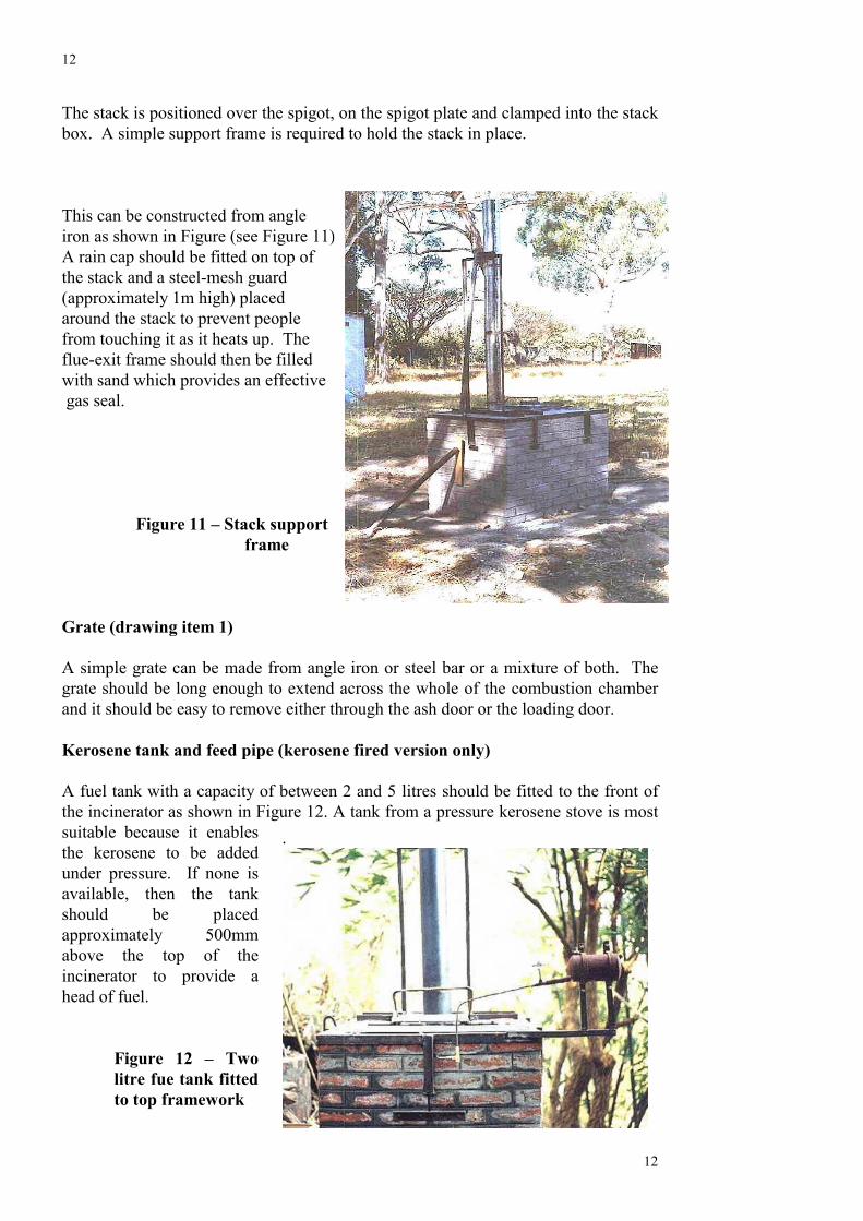
The stack is positioned over the spigot, on the spigot plate and clamped into the stackbox. A simple support frame is required to hold the stack in place.
This can be constructed from angle iron as shown in Figure (see Figure 11). A rain cap should be fitted on top of the stack and a steel-mesh guard (approximately 1m high) placed around the stack to prevent people from touching it as it heats up. The flue-exit frame should then be filled with sand which provides an effective gas seal.
Figure 11 – Stack support frame
Grate (drawing item 1)
A simple grate can be made from angle iron or steel bar or a mixture of both. Thegrate should be long enough to extend across the whole of the combustion chamberand it should be easy to remove either through the ash door or the loading door.
Kerosene tank and feed pipe (kerosene fired version only)
A fuel tank with a capacity of tween 2 and 5 litres should be fitted to the front ofthe incinerator as shown in Figsuitable because it enablesthe kerosene to be addedunder pressure. If none isavailable, then the tankshould be placedapproximately 500mmabove the top of theincinerator to provide ahead of fuel.
Figure 12 – Twolitre fue tank fittedto top framework
be
12
ure 12. A tank from a pressure kerosene stove is most.
13
13
The feed pipe enters the incinerator combustion chamber at one brick course belowthe top and should be sealed in position using fire cement. The tank should be fittedwith an on/off valve or tap to control the flow of kerosene. In addition, a simple pushbutton valve with a spring return can also be added to give better control over theflow of fuel. The button valve will also ensure that kerosene does not flow freelyinto the incinerator if the main flow-control valve is left open by mistake.
----------------------------------------------------------------------------------------
3 OPERATING THE INCINERATOR
3.1 SAFETY
Please read the following safety notes carefully:
3.1.1 When opening the loading door always wear eyeprotection and a face mask.
� Opening the loading door on either the wood or kerosene fired version duringoperation will mean that additional air will enter the combustion chamber. Thismay cause blow-back to occur and the flame to flare up out of the loading door.The blow-back does not last long but it could cause injury to anyone standing tooclose to the incinerator.
� Particular care should be taken when using kerosene as atomised vaporised fuel
may be present at the top of the combustion chamber which could ignitevigorously.
� The operator should open the door while standing at the front of the incinerator.The loading door is designed so that it hinges from the front of the incineratorand opens towards the operator. This provides the operator with some protectionfrom any blow-back and keeps him/her away from the opening to the combustionchamber.
� The operator should wait a few moments to allow any blow-back to die down
before loading waste materials into the incinerator.
3.1.2 Small explosions
� Some waste materials such as ampoules and glass bottles containing liquidvaccines and medicines may explode during incineration causing glass and
14
14
other waste materials to be blown into the atmosphere. The operator shouldensure that eye protection and a face mask is worn when opening the loadingdoor or when visually checking the combustion process through the air inletor when removing the ash door while the incinerator is in use.
3.1.3 Handling waste
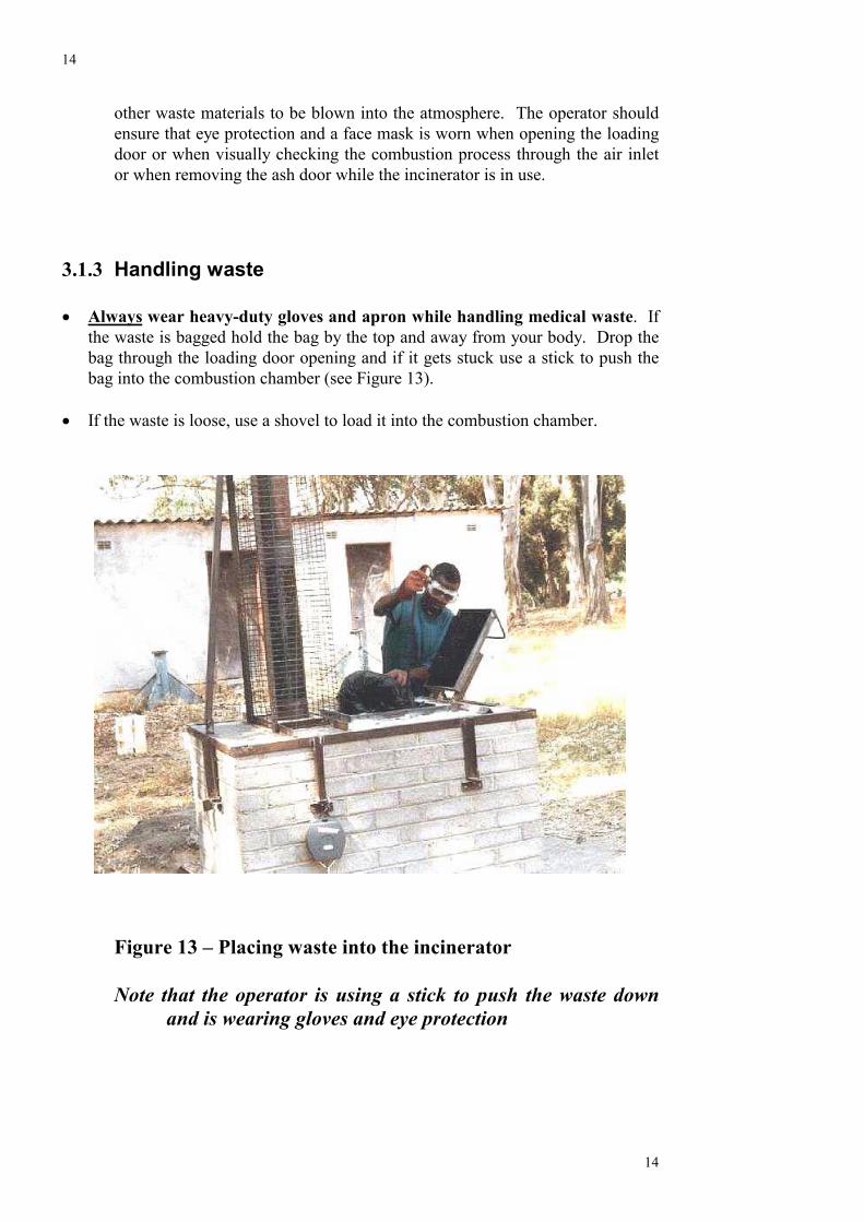
� Always wear heavy-duty gloves and apron while handling medical waste. Ifthe waste is bagged hold the bag by the top and away from your body. Drop thebag through the loading door opening and if it gets stuck use a stick to push thebag into the combustion chamber (see Figure 13).
� If the waste is loose, use a shovel to load it into the combustion chamber.
Figure 13 – Placing waste into the incinerator
Note that the operator is using a stick to push the waste downand is wearing gloves and eye protection
15
15
4 Removing ash and other solids from the combustionchamber
� Never handle the ash or other waste materials by hand. Use a stick or scraperto pull the solids out through the ash door and into a dustpan or box.
� Do not remove the ash or other waste materials from the combustion chamber
until they have cooled down. This will take about five hours. If theincinerator is in operation on a daily basis then the ashes and other wastematerial can be removed the following day as part of the preparation foroperation.
� Dispose of the ash and other waste materials carefully by burying or placing
in a skip for disposal by local authority or other authorised disposalcompany.
3.2 General operating notes
The following notes are intended to give the operator a basic understanding of how tooperate the incinerator. Optimum operation of this incinerator requires frequentattention to ensure that it performs effectively. It will take time for the operator tobecome familiar with the operation.
3.2.1 Waste management. Materials with high fuel values such as plastics, paper, card and dry textile will helpmaintain high incineration temperature. If possible a good mix of waste materialsshould be added with each batch. This can best be achieved by having the varioustypes of waste material loaded into separate bags at source i.e. the wards andlaboratories, and clearly labelled. It is not recommended that the operator sorts andthen mixes the waste prior to incineration as this is potentially hazardous.
The operator can then judge when to place which type of waste into the incinerator atany particular time. If possible some plastic materials should be added with eachbatch of waste as this burns at high temperatures. However, care and judgement willbe needed as too much plastic will create dense dark smoke. Wet kitchen wasteshould not be placed in the incinerator.
3.2.2 Operating temperatures
� The incinerator does not have a temperature gauge and so adequate operatingtemperatures have to be judged by the operator based on experience. A visual
16
16
guide is to look through the air inlet and at the colour of the smoke from the stack.If a good strong flame can be seen then the temperature should be more than800oC at this point and so will be adequate for good incineration. If the smoke isdark grey or black then poor combustion is occurring and the temperature will bebelow that required.
3.3 Starting and Operating the Wood Fuelled Version
• Open the loading door and ash door and remove any ash or other materials fromthe fire box, ensuring that the grate is clean and the entrance to the flue is notblocked.
• Before lighting the incinerator, prepare the fire wood, ensuring that it is dry andchopped or cut into short lengths (that fit horizontally through the loading door)and not more than 75 mm (3”) in section. If the wood has a high moisture content(i.e. above 15%) then it will be difficult to get the incinerator up to the operatingtemperature.
• Place paper on the grate and cover with dry kindling and small pieces of woodand/or dry textiles.
• Light the paper through the ash door and NOT through the loading door. (Thisprevents the operator being burnt if paper and kindling material flare upunexpectedly).
• Once the fire is established and burning well, start adding the fire wood in smallamounts.
• The loading door can be closed after about 5 minutes from lighting and once thefire is being drawn from the primary combustion chamber into the secondarychamber and up the stack.
• The ash door can be closed once the fire is well established. A well establishedfire will roar and will be audible through the air inlet tubes. Practice will enablethe operator to judge when the fire is established.
• Fire wood and/or dry waste is added at intervals until the incinerator is operatingat the right temperature. The operating temperature will be achieved between halfand one hour from lighting, depending on the ambient temperature, moisturecontent of the wood and the type of wood being used (i.e. hard, soft etc.)
• Once up to operating temperature, start to add the general waste material on smallbatches at regular intervals. The level of material in the incinerator should besuch that the incinerator is always above half full.
• If the waste is predominately unwanted drugs, straw or wood may be placed inthe incinerator before the drugs to hold the boxes in position for a longer periodin order to prevent pills falling through the incinerator without burning.
• Sharps, including hypodermics, should be mixed with other waste to preventthem falling through the incinerator without being destroyed.
• If the waste material has a high moisture content or has a low fuel value, woodcan be added to help maintain the correct operating temperature.
• The grate and flue entry should be checked every 15 minutes and raked clear ofany obstruction. This is to ensure that the airways are kept clear.
• At the end of the operating session and all the waste has been placed in theincinerator, add more wood to ensure that any waste residue has been completelyburned.
17
17
3.4 Starting and Operating the Kerosene Fuelled Version
• Open the loading door and ash door and remove any ash or other materials fromthe fire box, ensuring that the grate is clean and the entrance to the flue is notblocked.
• Place paper on the grate and cover with dry kindling and small pieces of woodand/or dry textiles.
• Light the paper through the ash door and NOT through the loading door. (Thisprevents the operator being burnt if paper and kindling material flare upunexpectedly).
• Once the fire is established and burning well, start adding more card, paperand/or dry waste and kerosene until the incinerator is up to the operatingtemperature. This will probably take about 1/2 an hour.
• The loading door can be closed after about 5 minutes from lighting and once thefire is being drawn from the primary combustion chamber into the secondarychamber and up the stack.
• The ash door can be closed once the fire is well established. A well establishedfire will roar and will be audible through the air inlet tubes. Practice will enablethe operator to judge when the fire is established.
• Once up to operating temperature, start to add the general waste material in smallbatches at regular intervals. The level of material in the incinerator should besuch that the incinerator is always above half full.
• If the waste is predominately unwanted drugs, straw may be placed in theincinerator before the drugs to hold the boxes in position for a longer period inorder to prevent pills falling through the incinerator without burning.
• Sharps, including hypodermics, should be mixed with other waste to preventthem falling through the incinerator without being destroyed.
• If the waste material has a high moisture content or has a low fuel value, kerosenecan be added to help maintain the correct operating temperature.
• The grate and flue entry should be checked every 15 minutes and raked clear ofany obstruction. This is to ensure that the airways are kept clear.
• At the end of the operating session and all the waste has been placed in theincinerator, add more paper, card and kerosene to ensure that any waste residuehas been completely burned.
Further information
In the first instance, for further information on the construction and operation of theincinerator, or to pass your experiences to the development team, please contactIntermediate Technology’s Technical Enquiry Service at:
Intermediate TechnologySchumacher Centre for Technology and DevelopmentBourton HallBourton on Dunsmore

18
18
Appendix 1
Appendix II
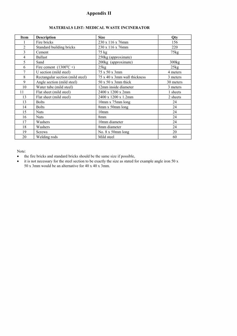
MATERIALS LIST: MEDICAL WASTE INCINERATOR
Item Description Size Qty1 Fire bricks 230 x 116 x 76mm 1562 Standard building bricks 230 x 116 x 76mm 2203 Cement 75 kg 75kg4 Ballast 250kg (approximate)5 Sand 200kg (approximate) 300kg6 Fire cement (1300oC +) 25kg 25kg7 U section (mild steel) 75 x 50 x 3mm 4 meters8 Rectangular section (mild steel) 75 x 40 x 3mm wall thickness 3 meters9 Angle section (mild steel) 50 x 50 x 3mm thick 30 meters
10 Water tube (mild steel) 12mm inside diameter 3 meters11 Flat sheet (mild steel) 2400 x 1200 x 2mm 1 sheets
13 Flat sheet (mild steel) 2400 x 1200 x 1.2mm 2 sheets13 Bolts 10mm x 75mm long 2414 Bolts 8mm x 50mm long 2415 Nuts 10mm 2416 Nuts 8mm 2417 Washers 10mm diameter 2418 Washers 8mm diameter 2419 Screws No. 8 x 50mm long 2020 Welding rods Mild steel 60
Note:� the fire bricks and standard bricks should be the same size if possible,� it is not necessary for the steel section to be exactly the size as stated for example angle iron 50 x
50 x 3mm would be an alternative for 40 x 40 x 3mm.