Embed Size (px)
Citation preview

FIMT User’s Tutorial
Rev
Developed with input and guidance
Prepared by:
ESRI Denver One International Court Broomfield, Colorado 80021
Tutorial ised: June 2005
ArcGIS Application for WildfireIncident Management
Version 9.0.3
by the USDA Forest Service from the interagency wildland community.
i

FIMT User’s Tutorial
Acknowledgements:
The Fire Incident Mapping Tool is greatly based on the Incident Command System (ICS). This method of managing a fire incident goes back for decades and the use of terms, processes, and symbols have been developed and used by many organizations to standardize to bringing of personnel from many different locations and have them be able to operate efficiently together. Any deviation from the ICS system will cause the use of this program to be questionable. As for the ArcGIS program, it is based on California Department of Forestry’s ArcView 3.x extension Ventura Tools. Since much of the problems associated with the data and how the program works with the data is simplified using ArcGIS and using a personal geodatabase. Ventura County Fire Department started the idea of creating the extension and was successful in getting CDF to take on the project. Much appreciation goes out to the people who were involved in the development and testing of the prototype version of the software. It was a group effort between Alberta Fire Protection and many different state and federal agencies in the U.S. This could not have been done without these people’s effort. Lastly, thanks to the Rocky Mountain Region of the USDA Forest Service for starting this project and getting out a program to make creation and management of Fire Incident data much easier and productive. If you have any comments, suggestions, and/or criticism, please contact one of the following: John Varner USDA Forest Service Rocky Mountain Region [email protected] 307-326-2551
Joe Frost USDA Forest Service Fire and Aviation Management [email protected] 208-387-5961
ii
FIMT User’s Tutorial
Table of Contents: Acknowledgements.......................................................................... ii FIMT Tools Tutorials: ....................................................................T-1 Tutorial: Installing the Data ............................................................................... T-1 Tutorial: Setting up a New Incident ................................................................... T-1 Tutorial: Opening an Existing Incident .............................................................. T-4 Tutorial: Adding Reference Data to your Incident ............................................. T-4 Tutorial: Creating the initial Incident data:......................................................... T-6 Tutorial: Adding Initial Assignment breaks. ....................................................... T-7 Tutorial: Annotating Initial Assignment breaks .................................................. T-9 Tutorial: Adding Fire lines from the Fire Polygon ............................................ T-11 Tutorial: Adding Fire Points from an existing Source ...................................... T-13 Tutorial: Creating Historical Snapshots........................................................... T-15 Tutorial: Modifying the Incident ....................................................................... T-15 Tutorial: Modifying the Fire Perimeter ............................................................. T-16 Tutorial: Modifying the Fire Perimeter, Adding Island Polygons...................... T-17 Tutorial: Modifying the Fire Perimeter, Updating Assignment breaks ............. T-18 Tutorial: Generating Fire Line Fire Perimeter Reports .................................... T-18 Appendix: ..................................................................................... AI-1 Appendix I: Tool Usage ................................................................................. AI-1 Group 1. Incident Tools ........................................................................... AI-1
Create Incident ......................................................................................... AI-1 Open Incident ........................................................................................... AI-2 Switch Incident.......................................................................................... AI-3 Edit Incident .............................................................................................. AI-3 Incident Information .................................................................................. AI-3 Copy to History ......................................................................................... AI-4 Copy Incident Layers to Data frame ......................................................... AI-4 Export to Shape file .................................................................................. AI-5
Group 2. Utility Functions ....................................................................... AI-5 Auto Update Measures ............................................................................ AI-5 Update Fire Names and Numbers ............................................................ AI-6 FIMT Feature Metadata ............................................................................ AI-7 Change FIMT Symbol Properties.............................................................. AI-8 Label Multiple Attributes ........................................................................... AI-9 Assign to Unit.......................................................................................... AI-10 Get Latitude/Longitude ........................................................................... AI-11
Group 3. Perimeter Tools ...................................................................... AI-12 Create Fire Perimeter ............................................................................. AI-12 Copy to Perimeter Layer ......................................................................... AI-13 Change Perimeter................................................................................... AI-13 Split Assignment Line ............................................................................. AI-13 Update Perimeter Assignment Breaks.................................................... AI-14 Create Island .......................................................................................... AI-15 Remove Island........................................................................................ AI-15 Convert Perimeter to Line....................................................................... AI-16 Perimeter Report .................................................................................... AI-16
iii
FIMT User’s Tutorial
Perimeter Change Report ....................................................................... AI-17 Draw History ........................................................................................... AI-17
Group 4. Fire Line Tools ........................................................................ AI-18 Create Fire Lines .................................................................................... AI-18 Copy to Fire Lines................................................................................... AI-18 Change Fire Line .................................................................................... AI-19 Split Fire Line.......................................................................................... AI-19 Join Fire Lines ........................................................................................ AI-20 Fire Line Report ...................................................................................... AI-21
Group 5. Fire Point Tools ...................................................................... AI-22 Create Fire Point..................................................................................... AI-22 Create Fire Point by Latitude/Longitude ................................................. AI-22 Copy to Fire Points ................................................................................. AI-24 Move Fire Point to Latitude/Longitude .................................................... AI-24 Change Fire Point................................................................................... AI-25
Ancillary utilities used by FIMT Tools........................................................ AI-25 Unit Assignment...................................................................................... AI-25 Feature Level Metadata Form................................................................. AI-26
iv

FIMT User’s Tutorial
This page intentionally left blank.
v
FIMT User’s Tutorial
FIMT Tools Tutorials:
Tutorial: Installing the Data A sample set of data has been created from the Colgate fire. The actual data contained in the Tutorial data set has been created to demonstrate steps you might actually perform during an incident. This is not real data and may not represent the actual procedures you follow. Using Windows Explorer, navigate to the tutorial CD (or folder) and run the setup.exe. Store the training data in any working directory you wish and make note of it since you will use this directory for the remaining tutorial steps (It will default to C:\Student. Tutorial narrative: The text shown in green italic font represents the tutorial narrative. These narratives are intended to emulate an incident scenario. These steps are strictly hypothetical and are not intended to represent the actual steps used at a real incident command.
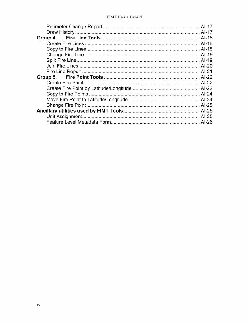
Tutorial: Setting up a New Incident Create a new map document, set map properties, and then load the FIMT Tools . Open ArcMap. Set the properties for your map document. Click the File menu, and then click Map Properties. Fill in the appropriate information on the Map Properties dialog.
T-1
FIMT User’s Tutorial
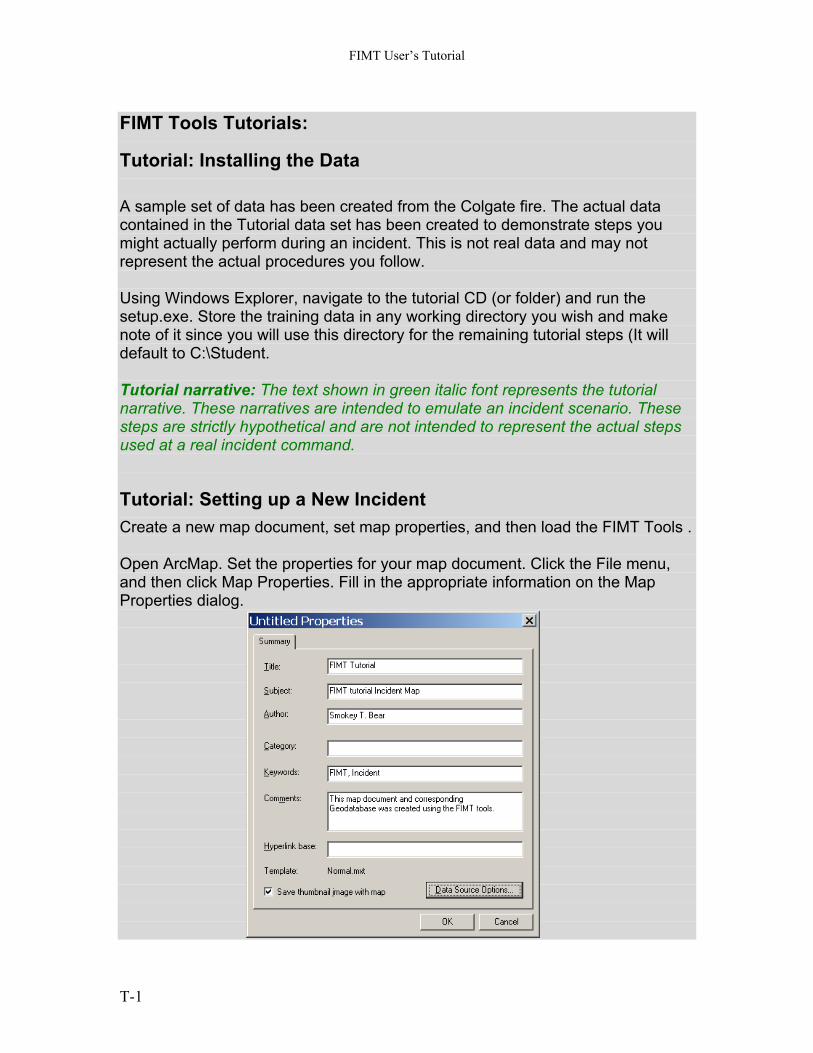
Click the Data Source Options… button to set your ArcMap document to use relative paths. This is especially important if you are going to be distributing you map document and data to other computers. Storing your data relative to the map document will eliminate the need to set the data source on other computers. 12. Click the Tools Menu, and then click Customize. 13. Check on the “Fire Incident Mapping Tool” from the Toolbar tab. 14. Dock the FIMT Toolbar to the ArcMap GUI in any location you like. 15. Click the Create Incident tool on the FIMT Toolbar. (Part of the
Incident Group) 16. For the purposes of the tutorial, enter the information shown on the
following graphic. 17. Click the Set Spatial Reference button to select a spatial reference. This
button will open the standard ArcGIS spatial reference properties menu. 18. Click the import… button. Note: For the purpose of the tutorial, you will be using a custom “Teale Albers” projection commonly used in the western U.S. (California, Oregon and Washington). The actual coordinate system you use will depend on the location of your incident, the size of the incident, and the coordinate system of available of supporting data such as digital orthophotography and digital raster graphics.
T-2
FIMT User’s Tutorial
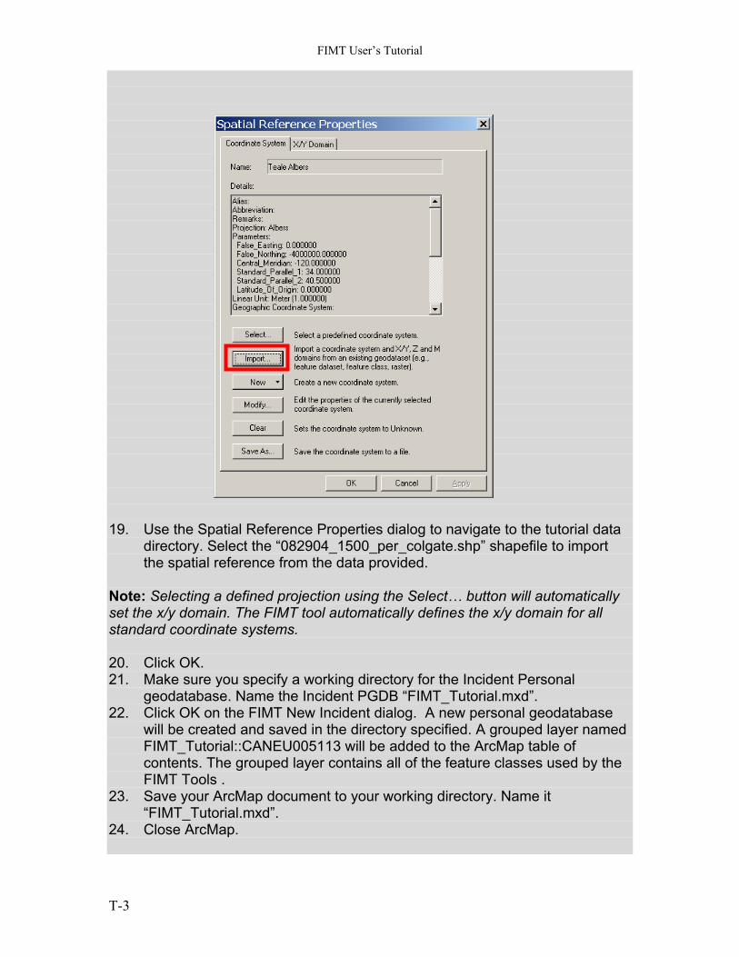
19. Use the Spatial Reference Properties dialog to navigate to the tutorial data
directory. Select the “082904_1500_per_colgate.shp” shapefile to import the spatial reference from the data provided.
Note: Selecting a defined projection using the Select… button will automatically set the x/y domain. The FIMT tool automatically defines the x/y domain for all standard coordinate systems. 20. Click OK. 21. Make sure you specify a working directory for the Incident Personal
geodatabase. Name the Incident PGDB “FIMT_Tutorial.mxd”. 22. Click OK on the FIMT New Incident dialog. A new personal geodatabase
will be created and saved in the directory specified. A grouped layer named FIMT_Tutorial::CANEU005113 will be added to the ArcMap table of contents. The grouped layer contains all of the feature classes used by the FIMT Tools .
23. Save your ArcMap document to your working directory. Name it “FIMT_Tutorial.mxd”.
24. Close ArcMap.
T-3
FIMT User’s Tutorial
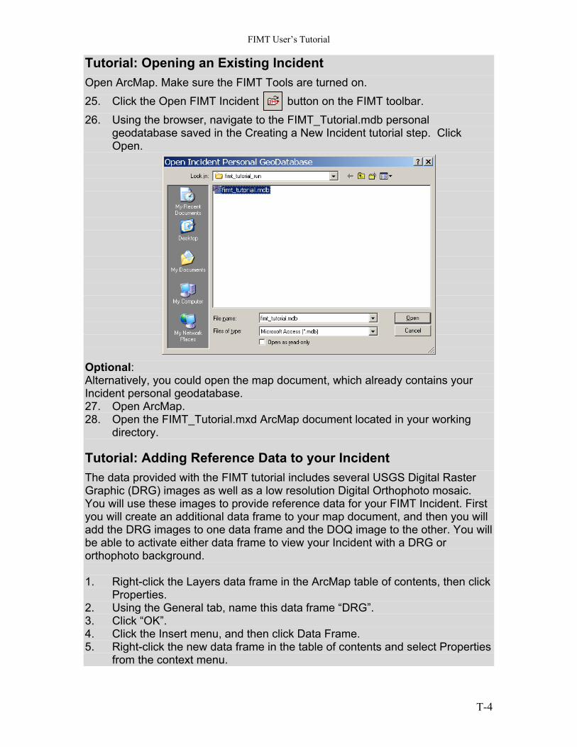
Tutorial: Opening an Existing Incident Open ArcMap. Make sure the FIMT Tools are turned on. 25. Click the Open FIMT Incident button on the FIMT toolbar. 26. Using the browser, navigate to the FIMT_Tutorial.mdb personal
geodatabase saved in the Creating a New Incident tutorial step. Click Open.
Optional: Alternatively, you could open the map document, which already contains your Incident personal geodatabase. 27. Open ArcMap. 28. Open the FIMT_Tutorial.mxd ArcMap document located in your working
directory.
Tutorial: Adding Reference Data to your Incident The data provided with the FIMT tutorial includes several USGS Digital Raster Graphic (DRG) images as well as a low resolution Digital Orthophoto mosaic. You will use these images to provide reference data for your FIMT Incident. First you will create an additional data frame to your map document, and then you will add the DRG images to one data frame and the DOQ image to the other. You will be able to activate either data frame to view your Incident with a DRG or orthophoto background. 1. Right-click the Layers data frame in the ArcMap table of contents, then click
Properties. 2. Using the General tab, name this data frame “DRG”. 3. Click “OK”. 4. Click the Insert menu, and then click Data Frame. 5. Right-click the new data frame in the table of contents and select Properties
from the context menu.
T-4
FIMT User’s Tutorial
6. Using the General tab, name this data frame “DOQ”. 7. Using the “Coordinate System,” tab, set the coordinate system by importing
from an existing source. Navigate to the tutorial data directory. Select the “082904_1500_per_colgate.shp” shapefile to import the spatial reference from the data provided.
8. Click “OK” to close the data frame properties dialog box. 9. Right-click the DRG data frame, then click Activate. This data frame should
be in bold text on the table of contents indicating that it is the active data frame.
10. Click the ArcMap Add Data button, and browse to images directory contained in the FIMT Tutorial install directory.
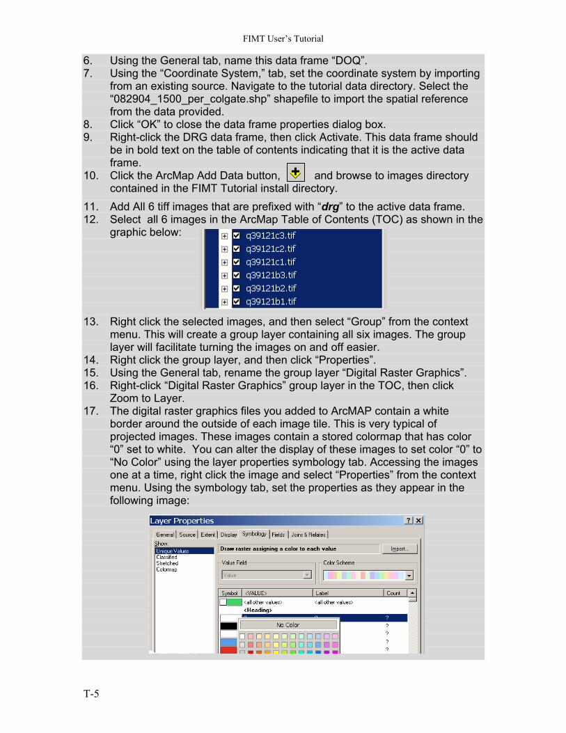
11. Add All 6 tiff images that are prefixed with “drg” to the active data frame. 12. Select all 6 images in the ArcMap Table of Contents (TOC) as shown in the
graphic below: 13. Right click the selected images, and then select “Group” from the context
menu. This will create a group layer containing all six images. The group layer will facilitate turning the images on and off easier.
14. Right click the group layer, and then click “Properties”. 15. Using the General tab, rename the group layer “Digital Raster Graphics”. 16. Right-click “Digital Raster Graphics” group layer in the TOC, then click
Zoom to Layer. 17. The digital raster graphics files you added to ArcMAP contain a white
border around the outside of each image tile. This is very typical of projected images. These images contain a stored colormap that has color “0” set to white. You can alter the display of these images to set color “0” to “No Color” using the layer properties symbology tab. Accessing the images one at a time, right click the image and select “Properties” from the context menu. Using the symbology tab, set the properties as they appear in the following image:
T-5
FIMT User’s Tutorial
18. Right-click the DOQ data frame, then click Activate. 19. The DOQ data frame should be active. This data frame should not contain
any layers. 20. Click the Copy FIMT Layers to Dataframe button on the FIMT
toolbar. This button will copy all of the FIMT Incident layers to the data frame. (This tool is part of the Incident group).
Note: The “Copy FIMT to Dataframe” tool makes a copy of each FIMT feature class from the active incident database into the active Dataframe. Since this is a copy of the active incident database, editing can take place in either data frame. 21. Click the ArcMap Add Data button, and browse to FIMT Tutorial data
directory. 22. Add the DOQ.tif image to the active data frame. Ignore the warning about
the missing spatial reference if it appears. 23. Right click the DOQ image in the table of contents, then click Zoom to
Layer. 24. Save your map document.
Tutorial: Creating the initial Incident data: Tutorial narrative: In the initial phases of this Incident, it is August 29, 2004 and you are assigned to the FIMT Tutorial Incident. At 20:00, the Situation Unit Leader informs you that he will need the IAP map for the morning IAP packet. Your IAP will be for the day shift on August 30th and it will be distributed at the 6 a.m. morning briefing. You have received the initial perimeter, contained in a shapefile, from the infrared interpreter. The shapefile is located in the FIMT Tutorial installation directory. The file is named 082904_1500_per_colgate.shp. You have also received a GPS shapefile from a field crew. The shapefile contains waypoint information. You will use the table definitions for each waypoint to build FIMT points and to assign branch/division breaks to the fire polygon. The shapefile is located in the FIMT Tutorial installation directory. The file is named 082904_1500_wayp_colgate.shp. 25. Click the DRG data frame and click Activate if it is not the current active
data frame. 26. Click the Add Data button, and browse to your FIMT Tutorial install
directory. 27. Add the 082904_1500_per_colgate.shp shapefile to the active data frame. 28. Start the editing environment on the Incident personal geodatabase. Click
the “Edit Incident” button. (Part of the Incident group)
T-6
FIMT User’s Tutorial
Note: You can also start editing by selecting “Start Editing” from the Editor Toolbar > Editor Pull down menu. Several of the FIMT Tools that were previously grayed out should now be enabled. Next you will select the source perimeter and copy it to the FirePolygon feature class. ArcMap Tip: from this point on in the editing process, you will be frequently switching selected sets. You can add the selection tab to the Table of Contents to make this task easier. Open the Options dialog under the Tools > Options menu. Activate the TOC tab, and then check the Selection check box in the TOC Tab Options control panel. Click OK to close the Options dialog. 29. Set the selectable layer to 082904_1500_per_colgate.shp. 30. Use the Select Features tool to select the perimeter contained in the
selectable layer. 31. Click the Copy to Perimeter Layer button on the FIMT toolbar. (Part of
the Perimeter group) 32. Right-click the 082904_1500_per_colgate.shp layer, then click Remove. Examine the contents of the FirePolygon feature class. Notice it now contains the polygon that was selected from the 082904_1500_per_colgate shapefile. This process can be used to move any selected polygon from any valid polygon vector data source into the FirePolygon feature class. Also examine the contents of the PerimeterSector feature class. You will notice that this feature class now contains a line that matches the shape of the fire perimeter. The PerimeterSector feature class contains linear features that are used for attributing assignment breaks in relation to the fire perimeter.
Tutorial: Adding Initial Assignment breaks. Tutorial narrative: You will use the attributed WayPoints to create assignment breaks on the PerimeterSector feature class in the FIMT Tutorial Incident geodatabase. Your Situation Unit Leader has informed you that the FirePerimeter has been assigned the following Branch/Divisions. Branch I – Div A, B, C, D Branch II – Div E, F, G, H Branch III – Div T, U, V, W Branch IV – Div X, Y, Z The 082904_1500_wayp_colgate shapefile contains two attribute columns that you will use to construct your IAP map. The WAYPOINT column contains a label text string. The TYPE field contains the WAYPOINT category. You will label the WAYPOINT layer so you can see the Division breaks. You will use the TYPE field to create a definition query to display only the Division/Branch break points to simplify the map display.
T-7
FIMT User’s Tutorial
1. Click the Add Data button, and browse to your FIMT Tutorial install directory.
2. Add the 082904_1500_wayp_colgate.shp shapefile to the active data frame.
3. Right click the 082904_1500_wayp_colgate.shp, and then click “Properties…”
4. In the Labels tab on the Layers Properties dialog, check the “Label Features in this Layer” check box. Verify or set the Label Field to the WAYPOINT attribute column.
5. In the Definition Query Tab, use the Query builder to construct the following query string: "TYPE" = 'DivBrk'.
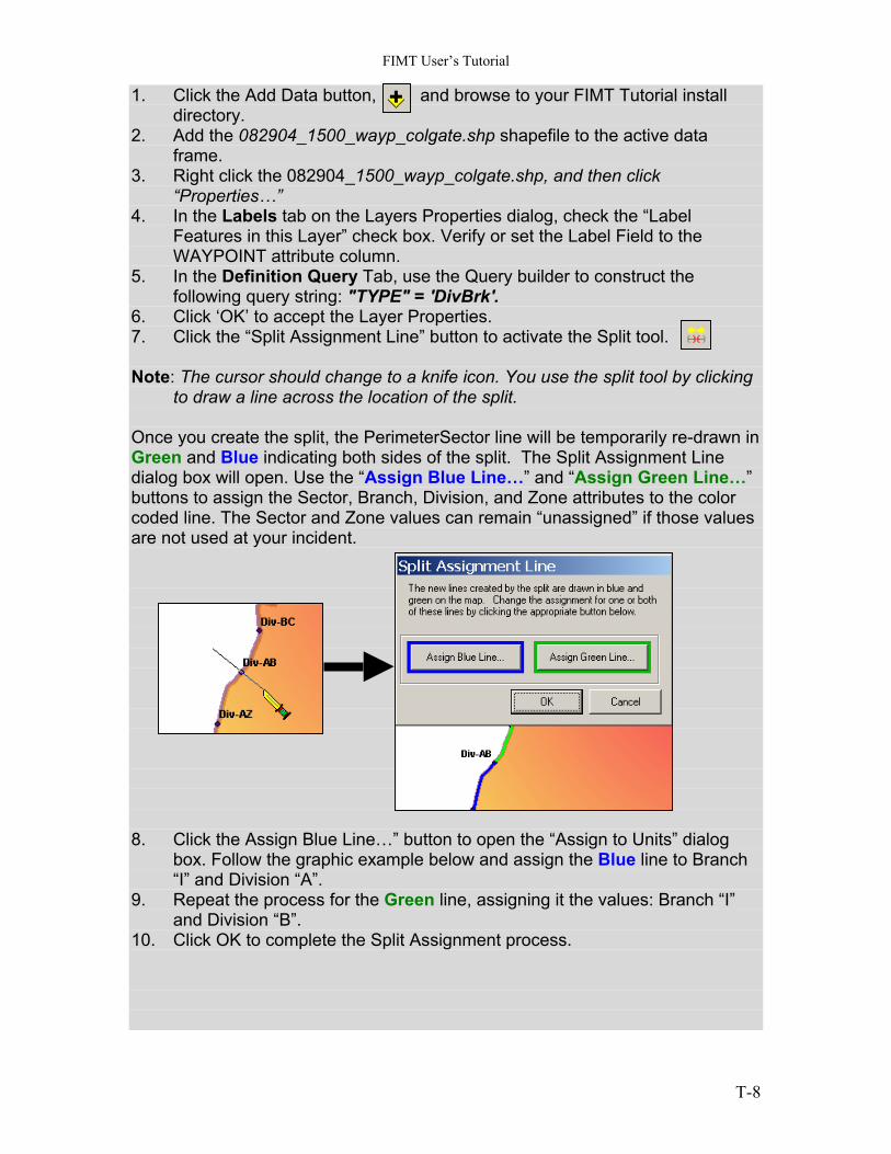
6. Click ‘OK’ to accept the Layer Properties. 7. Click the “Split Assignment Line” button to activate the Split tool. Note: The cursor should change to a knife icon. You use the split tool by clicking
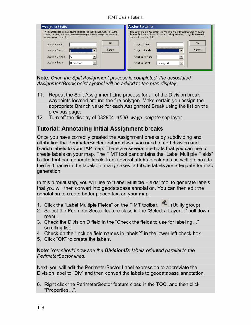
to draw a line across the location of the split. Once you create the split, the PerimeterSector line will be temporarily re-drawn in Green and Blue indicating both sides of the split. The Split Assignment Line dialog box will open. Use the “Assign Blue Line…” and “Assign Green Line…” buttons to assign the Sector, Branch, Division, and Zone attributes to the color coded line. The Sector and Zone values can remain “unassigned” if those values are not used at your incident. 8. Click the Assign Blue Line…” button to open the “Assign to Units” dialog
box. Follow the graphic example below and assign the Blue line to Branch “I” and Division “A”.
9. Repeat the process for the Green line, assigning it the values: Branch “I” and Division “B”.
10. Click OK to complete the Split Assignment process.
T-8
FIMT User’s Tutorial
Note: Once the Split Assignment process is completed, the associated AssignmentBreak point symbol will be added to the map display. 11. Repeat the Split Assignment Line process for all of the Division break
waypoints located around the fire polygon. Make certain you assign the appropriate Branch value for each Assignment Break using the list on the previous page.
12. Turn off the display of 082904_1500_wayp_colgate.shp layer.
Tutorial: Annotating Initial Assignment breaks Once you have correctly created the Assignment breaks by subdividing and attributing the PerimeterSector feature class, you need to add division and branch labels to your IAP map. There are several methods that you can use to create labels on your map. The FIMT tool bar contains the “Label Multiple Fields” button that can generate labels from several attribute columns as well as include the field name in the labels. In many cases, attribute labels are adequate for map generation. In this tutorial step, you will use to “Label Multiple Fields” tool to generate labels that you will then convert into geodatabase annotation. You can then edit the annotation to create better placed text on your map. 1. Click the “Label Multiple Fields” on the FIMT toolbar. (Utility group) 2. Select the PerimeterSector feature class in the “Select a Layer…” pull down
menu. 3. Check the DivisionID field in the “Check the fields to use for labeling…”
scrolling list. 4. Check on the “Include field names in labels?” in the lower left check box. 5. Click “OK” to create the labels. Note: You should now see the DivisionID: labels oriented parallel to the PerimeterSector lines. Next, you will edit the PerimeterSector Label expression to abbreviate the Division label to “Div” and then convert the labels to geodatabase annotation. 6. Right click the PerimeterSector feature class in the TOC, and then click
“Properties…”.
T-9
FIMT User’s Tutorial
7. On the Labels tab, click the “Expression…” button. 8. In the Expression text box, edit the existing expression to contain the
following: "Div" &[DivisionID]. 9. Click the “Verify” button to make sure your expression syntax is correct. 10. Click OK to accept the expression, and then click OK to close the Layer
Properties dialog. 11. Right click the PerimeterSector feature class in the TOC, then click “Convert
Labels to Annotation…” . 12. Check off the “Display overlapping labels in the overflow window” check box. 13. Make sure the “In a Database” radio button is selected in the “Store
Annotation” control panel. 14. Check off the “Feature Linked” check box to create simple annotation that is
not linked to the PerimeterSector feature class. 15. Change the name contained in the Annotation Feature Class box to
“DivisionAnno”. 16. Click Convert on the “Convert Labels to Annotation” dialog to create the
annotation. The DivisionAnno feature class should now be added to your map display. Next, you will orient the Annotation horizontal, and then position the individual text to the outside of the fire polygon. 17. Click the “Edit” tool on the ArcMap Editor toolbar. 18. Use the Edit tool to select ALL the annotation on the map display. The
selected annotation should be highlighted with a blue box. 19. Position the cursor over any of the selected annotations, right click, and then
select “Attributes…” from the context menu. You can also click the “Attributes” button on the Editor toolbar.
20. Select the top most element in the right-hand list of elements on the Attributes
dialog. This element should be the name of the Annotation feature class. 21. On the “Attributes” tab, enter the angle 0 in the Angle textbox, and then press
“Enter” on your keyboard. All of the selected Annotations should now be rotated to a horizontal position. 22. Using the “Edit” tool, select each annotation one at a time and drag it to a
location outside the fire polygon in a position between each assignment break symbol. Note: you can also use the “Select Elements” tool on the ArcMap toolbar to reposition annotation.
Using steps 1-21 above, repeat this process to create annotation for the Branch assignments. Modify the label text expression to read “Branch” in addition to the individual Branch number (i.e. “Branch: IV”). Position these annotations outside the fire polygon between the Branch assignment break symbols.
T-10
FIMT User’s Tutorial
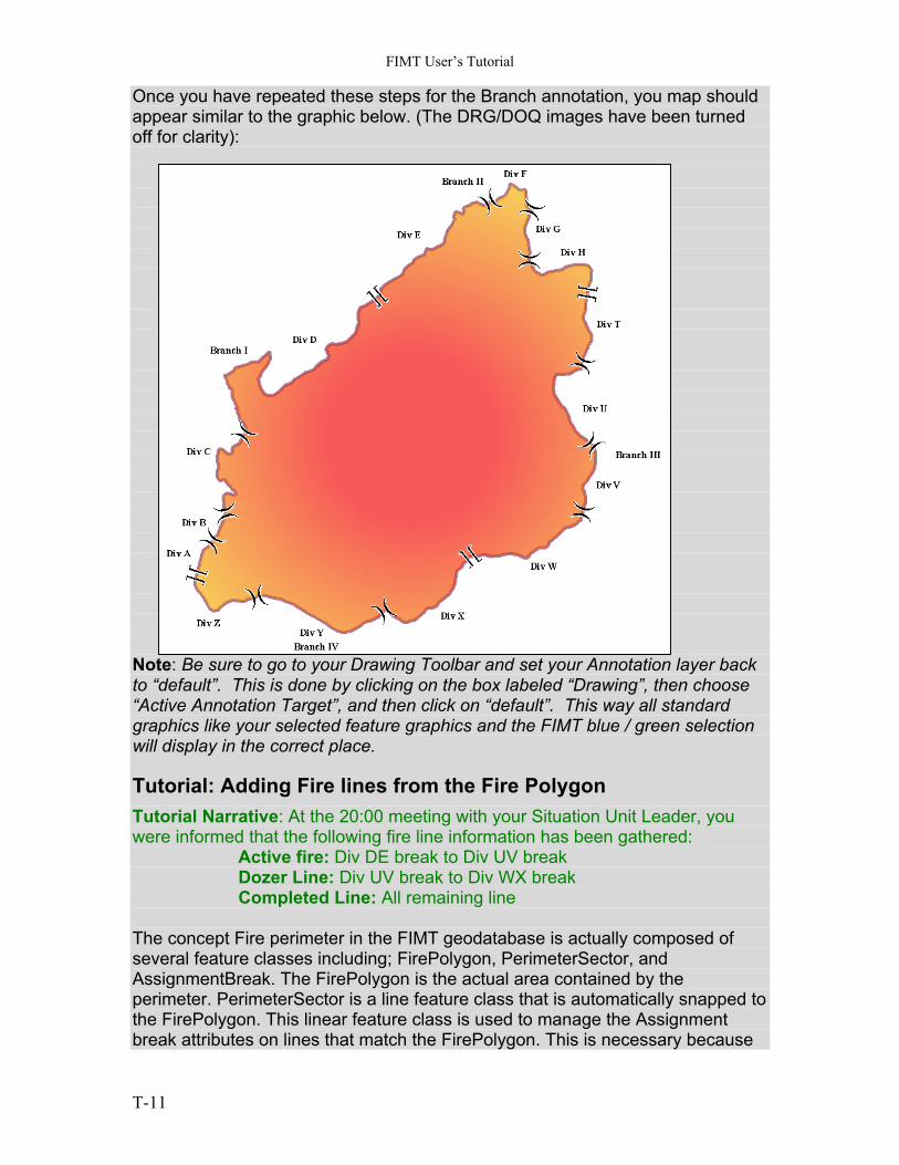
Once you have repeated these steps for the Branch annotation, you map should appear similar to the graphic below. (The DRG/DOQ images have been turned off for clarity): Note: Be sure to go to your Drawing Toolbar and set your Annotation layer back to “default”. This is done by clicking on the box labeled “Drawing”, then choose “Active Annotation Target”, and then click on “default”. This way all standard graphics like your selected feature graphics and the FIMT blue / green selection will display in the correct place.
Tutorial: Adding Fire lines from the Fire Polygon Tutorial Narrative: At the 20:00 meeting with your Situation Unit Leader, you were informed that the following fire line information has been gathered:
Active fire: Div DE break to Div UV break Dozer Line: Div UV break to Div WX break Completed Line: All remaining line The concept Fire perimeter in the FIMT geodatabase is actually composed of several feature classes including; FirePolygon, PerimeterSector, and AssignmentBreak. The FirePolygon is the actual area contained by the perimeter. PerimeterSector is a line feature class that is automatically snapped to the FirePolygon. This linear feature class is used to manage the Assignment break attributes on lines that match the FirePolygon. This is necessary because
T-11
FIMT User’s Tutorial
the geodatabase cannot store linear attributes on a polygon feature class (FirePolygon). AssignmentBreak is a point feature class used to symbolize changes in assignment breaks. You can use the PerimeterSector features to copy these line segments into the FireLine feature class to create fire lines that follow or conform to the FirePolygon. 1. Right click the PerimeterSector feature class, then select “Selection” > “Select
All”. 2. Click the “Copy to FireLines” button on the FIMT Toolbar. (FireLine tools) 3. Click off the PerimeterSector feature class in the TOC. 4. Verify that the FireLine feature class in visible. 5. On the TOC Selection tab, make the FireLine feature class the only
selectable layer. 6. Use the “Select Features” tool to select the line segments from Div DE break
to Div UV break. You should have six (6) lines selected. 7. Click the “Attributes” button to open the “Attributes” dialog. 8. In the left pane of the “Attributes” dialog, click on the top most “FireLine”
group. The right panel should contain a list of Properties (attribute columns) with no visible attribute values.
9. Click to the right of the “FLType” property to activate the FireLine Type domain.
10. Select “Uncontrolled Fire Edge” from the pull down list of domain values. Note: These lines were copied from the PerimeterSector feature class so there are six selected Fire lines of the same type. Note: You should also use the ”Assign to Unit” tool to assign Branch/Division values to the selected fire lines as well as the “Metadata” tool to add metadata about the selected fire lines. You should experiment with these additional buttons to become familiar with their operation. Note: When using the Attribute dialog, you can set the attributes for an entire selected set by selecting the top of the selected set in the left panel. You will not actual see the attribute values in the right panel. They will however be set and visible in the individual records. Next, you will use the FIMT “Change FireLine” tool to set the fire line type to “Completed Dozer line” for the Lines from Div UV break to Div WX break. 11. Select the two lines represented between the breaks described above. 12. Use the Editor > Merge operation to merge the selected lines into a single line
segment. Make certain the FireLine feature class is the only selectable layer. 13. Click the “Change FireLine” tool on the FIMT toolbar. (FireLine tools) Note: The 9.0.3 version of the FIMT tools supports changing multiple selected lines. This was not possible in the older versions of FIMT.
T-12
FIMT User’s Tutorial
14. Select “Completed Dozer Line” from the Pull down list of FireLine types. 15. Click OK to apply the change to the FireLine attributes. 16. Repeat steps 11-15 for the remaining unassigned Firelines. Set the FireLine
type to “Completed Line”.
Tutorial: Adding Fire Points from an existing Source Tutorial Narrative: The 082904_1500_wayp_colgate shapefile contains additional way points that need to be added to your FIMT Tutorial database as a variety of different fire point types. 1. Right click the 082904_1500_wayp_colgate shapefile in the TOC, and then
click “Properties…” . 2. On the “Definition Query” tab, click the “Query Builder…” button. 3. On the Query Builder dialog, click the clear button. 4. Using any method, create a query string as follows: "TYPE" <> 'DivBrk' (This
query will query out all points except the Division Break points you have already used.
5. Click the “Verify” button to make sure your query syntax is correct. Note: Your 082904_1500_wayp_colgate layer should still be labeled with the WayPoint field. If not, set the layer properties to label with this field. 6. Right click the 082904_1500_wayp_colgate layer in the TOC, and then click
Select > Select All. 7. Click the “Copy to FirePoints” button on the FIMT toolbar to copy the selected
points into the FirePoint feature class. (FirePoint tools) 8. Make certain the FirePoint feature class is turned on. Note: Once you copy the selected points into the FirePoint feature class, you should see the new FirePoints displayed as red question marks indicating the FirePoint type is unknown. You must now set the FirePoint type from unknown to the correct fire point type based on the WayPoint label in the source shape file. Using the “Change FirePoint” tool on the FIMT toolbar, you will set the attribute values one at a time. 9. On the TOC Selection TAB, set the FirePoint as the selectable layer. 10. Select one of the FirePoints displaying the Unknown point type. (Red
question mark). 11. Click the “Change FirePoint” tool on the FIMT toolbar. (FirePoint tools) Tutorial Narrative: The Waypoint shapefile contains the following FirePoint types: DP = Drop point, enter the “DP-” and the number in the Name field Staging = Staging Area, enter the name in the Name field ICP = Incident Command Post, enter “ICP” in the Name field Base = Incident Base, enter “Base” in the name field Origin = Fire Origin, set Name field blank
T-13
FIMT User’s Tutorial
12. Repeat steps 10-11 for all of the remaining Unknown fire points. 13. Right-click the 082904_1500_wayp_colgate.shp layer, then click Remove. Note: The “Copy to FirePoint” tool automatically adds the text string “Not Set” in the name field for all copied points. Make sure to set the Name field blank for all fire points that do not have a name. This will prevent the string “Not Set” from displaying in labels using the Name field. Note: The FirePoint feature class is added by default below the other FIMT feature classes in the TOC. You can move this feature class to the top by dragging it in the Display tab of the TOC. 14. Click the “Label Multiple Fields” tool on the FIMT toolbar to label the
FirePoints. Set the layer to FirePoint, and check on the Name field for labeling. Click OK to draw the label.
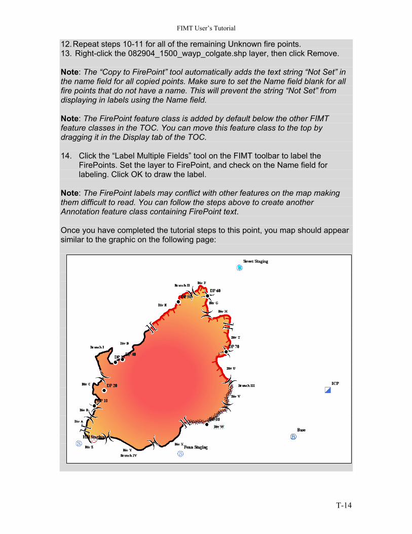
Note: The FirePoint labels may conflict with other features on the map making them difficult to read. You can follow the steps above to create another Annotation feature class containing FirePoint text. Once you have completed the tutorial steps to this point, you map should appear similar to the graphic on the following page:
T-14
FIMT User’s Tutorial
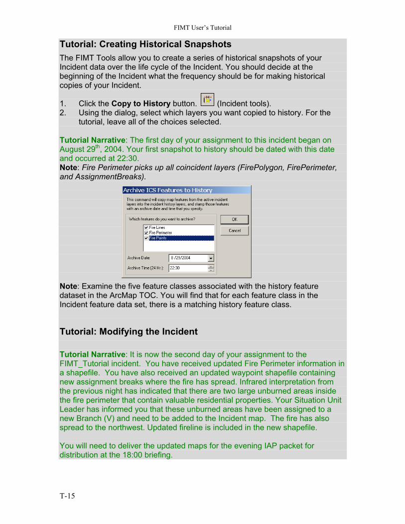
Tutorial: Creating Historical Snapshots The FIMT Tools allow you to create a series of historical snapshots of your Incident data over the life cycle of the Incident. You should decide at the beginning of the Incident what the frequency should be for making historical copies of your Incident. 1. Click the Copy to History button. (Incident tools). 2. Using the dialog, select which layers you want copied to history. For the
tutorial, leave all of the choices selected. Tutorial Narrative: The first day of your assignment to this incident began on August 29th, 2004. Your first snapshot to history should be dated with this date and occurred at 22:30. Note: Fire Perimeter picks up all coincident layers (FirePolygon, FirePerimeter, and AssignmentBreaks). Note: Examine the five feature classes associated with the history feature dataset in the ArcMap TOC. You will find that for each feature class in the Incident feature data set, there is a matching history feature class.
Tutorial: Modifying the Incident Tutorial Narrative: It is now the second day of your assignment to the FIMT_Tutorial incident. You have received updated Fire Perimeter information in a shapefile. You have also received an updated waypoint shapefile containing new assignment breaks where the fire has spread. Infrared interpretation from the previous night has indicated that there are two large unburned areas inside the fire perimeter that contain valuable residential properties. Your Situation Unit Leader has informed you that these unburned areas have been assigned to a new Branch (V) and need to be added to the Incident map. The fire has also spread to the northwest. Updated fireline is included in the new shapefile. You will need to deliver the updated maps for the evening IAP packet for distribution at the 18:00 briefing.
T-15
FIMT User’s Tutorial
Tutorial: Modifying the Fire Perimeter Note: There are several methods that can be used to reshape an existing FirePolygon. This tutorial demonstrates only a few valid methods. It is important to remember the FirePolygon is synchronized with the PerimeterSector feature class and the AssignmentBreak feature class through the FIMT extension. If you encounter behavior using the FIMT extension that indicated these feature classes are no longer synchronizing, you should undo at least last the change and save your edits and map document, exit and then restart ArcMap. 1. Navigate to the Tutorial install directory and add the following shapefiles to
you map document. 083004_1550_update.shp 083004_1500_wayp_colgate 2. Zoom in to an area containing the two perimeter update lines in the NW
area of the FirePolygon. 3. On the Editor toolbar, set the Target Layer to “FirePolygon”, and set the
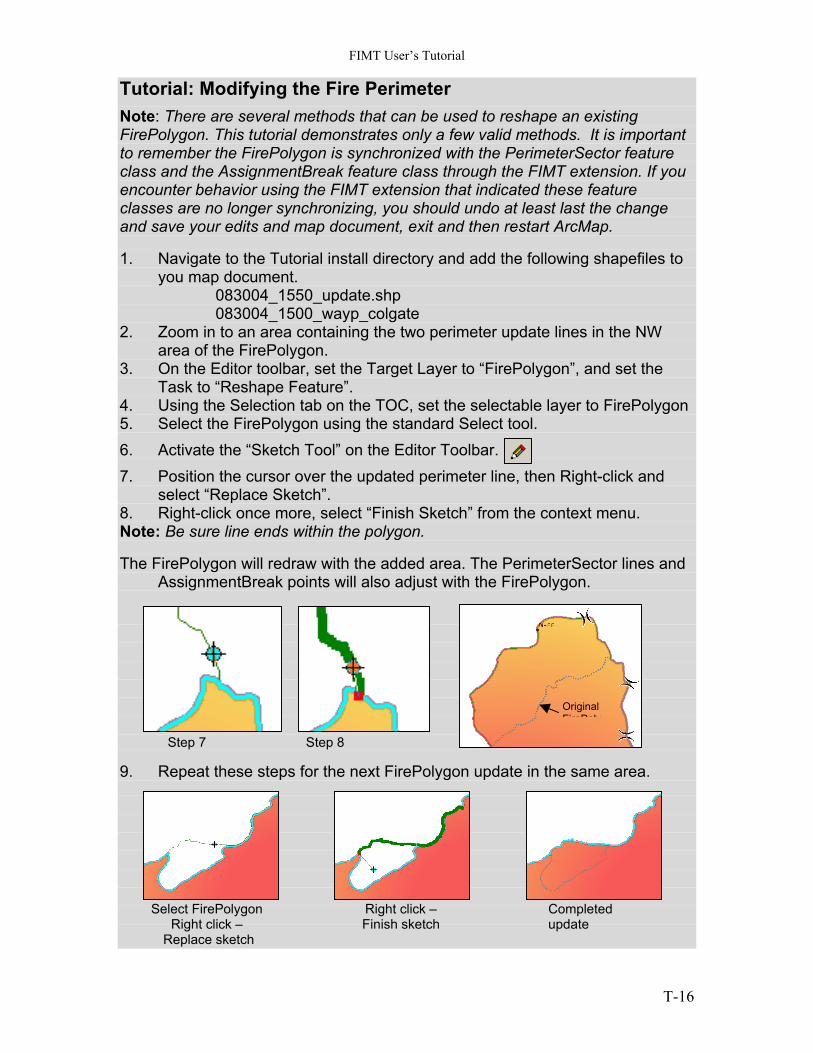
Task to “Reshape Feature”. 4. Using the Selection tab on the TOC, set the selectable layer to FirePolygon 5. Select the FirePolygon using the standard Select tool. 6. Activate the “Sketch Tool” on the Editor Toolbar. 7. Position the cursor over the updated perimeter line, then Right-click and
select “Replace Sketch”. 8. Right-click once more, select “Finish Sketch” from the context menu. Note: Be sure line ends within the polygon. The FirePolygon will redraw with the added area. The PerimeterSector lines and
AssignmentBreak points will also adjust with the FirePolygon.
Original FirePoly
Step 7 Step 8 9. Repeat these steps for the next FireP Select FirePolygon
Right click – Replace sketch
Right cliFinish sk
olygon update in the same area.
ck – etch
Completed update
T-16
FIMT User’s Tutorial
Tutorial: Modifying the Fire Perimeter, Adding Island Polygons Note: The FIMT toolbar contains tools for creating and deleting FirePolygon island exclusions. You should always use the FIMT tools to create these features. Using ArcMap standard edit tasks will result in unpredictable behavior. 1. Zoom to the center of the existing FirePolygon where there are two update
polylines. You will use these lines to create the Island polygons. 2. Click the “Create Island” tool on the FIMT toolbar. (Perimeter tools). Note: The Editor Target is automatically set to FirePolygon and the Edit task is set to “FIMT Create Island”. Do not attempt to create an island polygon using any other combination. 3. Using the Selection tab on the TOC, set the selectable layer to the
FirePolygon, and the 083004_1550_update shapefile. 4. Select both the FirePolygon and one of the 083004_1550_update polylines
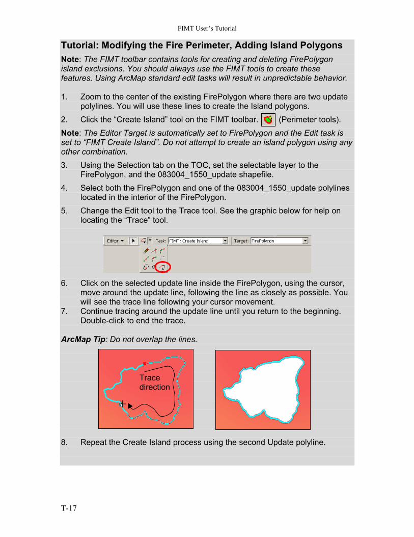
located in the interior of the FirePolygon. 5. Change the Edit tool to the Trace tool. See the graphic below for help on
locating the “Trace” tool. 6. Click on the selected update line inside the FirePolygon, using the cursor,
move around the update line, following the line as closely as possible. You will see the trace line following your cursor movement.
7. Continue tracing around the update line until you return to the beginning. Double-click to end the trace.
ArcMap Tip: Do not overlap the lines.
Trace direction
8. Repeat the Create Island process using the second Update polyline.
T-17
FIMT User’s Tutorial
Tutorial: Modifying the Fire Perimeter, Updating Assignment breaks The update shapefile 083004_1500_wayp_colgate contains updated division break points. Use the skills previous learned to update the Assignment breaks where the FirePolygon has expanded in the northwest direction, and add assignment breaks to the unburned islands where indicated by a new waypoint. Use labels to help you locate and attribute the Branch and Division assignments. All of the Islands are assigned to Branch V.
Tutorial: Generating Fire Line Fire Perimeter Reports The FIMT Tools include the ability to generate reports for fire perimeters and for fire lines. These reports can be copied to the Windows clipboard and pasted into any text editor and they can be pasted into an ArcMap layout for inclusion in a hardcopy map. 1. Click the “Perimeter Report” button . Examine the contents of the
report. 2. Click the Copy button on the Perimeter Report and close the dialog. 3. From the Windows Start menu, click Start > Programs > Accessories >
WordPad. 4. In WordPad, click Edit, and then click Paste. The contents of your report are
now pasted into the WordPad document. Next, you will include a report in your ArcMap layout. 5. Click the “Fire Line Report” Button . Examine the contents of the
report. 6. Click the Copy button on the Fire Line report. 7. In ArcMap, toggle to the map Layout view. 8. Click Edit, and then click Paste. 9. The text from the Fire Line report is now pasted into the map layout. 10. Double click on the pasted text to activate the text property sheet. 11. Modify the properties of the text to best fit the report on the map layout. 12. Save the map document and close ArcMap.
T-18
FIMT User’s Tutorial
Appendix:
Appendix I: Tool Usage
Group 1. Incident Tools
Create Incident
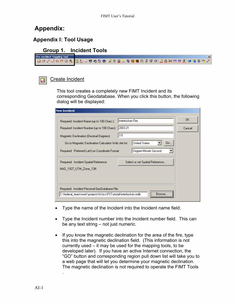
This tool creates a completely new FIMT Incident and its corresponding Geodatabase. When you click this button, the following dialog will be displayed:
• Type the name of the Incident into the Incident name field.
• Type the Incident number into the Incident number field. This can be any text string – not just numeric.
• If you know the magnetic declination for the area of the fire, type
this into the magnetic declination field. (This information is not currently used – it may be used for the mapping tools, to be developed later). If you have an active Internet connection, the “GO” button and corresponding region pull down list will take you to a web page that will let you determine your magnetic declination. The magnetic declination is not required to operate the FIMT Tools .
AI-1
FIMT User’s Tutorial
• Select the coordinate format you would like to use for entering
latitude/longitude coordinates for this project. This will become the default coordinate format, used whenever you are asked to enter lat/long input. You can change this later if you want, or you can override it on the lat/long input dialogs for one-time exceptions.
• Select the spatial reference you want to use for the Incident
database. This is required only because ArcMap needs to know: a) How to store the data you are going to create through the application, b) How to project raw lat/long and GPS coordinates into your Incident database, and c) How to project your Incident data to match other data you may have, or to match the spatial reference of your ArcMap display. To set the spatial reference, click the Set Spatial Reference button. This will bring up the Spatial Reference Properties dialog (the same one as used in ArcCatalog). From here, you can select a standard spatial reference, or define your own. (Note: When in doubt, use the UTM projection for the Incident area).
• Specify the name of your new FIMT database and where it should
be stored using the Browse button next to the geodatabase name field.
• Click OK and the new Incident database will be created for you.
The standard FIMT Incident layers will be created from this database and loaded into your current data frame automatically.
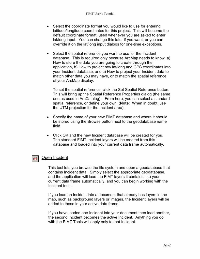
Open Incident
This tool lets you browse the file system and open a geodatabase that contains Incident data. Simply select the appropriate geodatabase, and the application will load the FIMT layers it contains into your current data frame automatically, and you can begin working with the Incident tools. If you load an Incident into a document that already has layers in the map, such as background layers or images, the Incident layers will be added to those in your active data frame. If you have loaded one Incident into your document then load another, the second Incident becomes the active Incident. Anything you do with the FIMT Tools will apply only to that Incident.
AI-2
FIMT User’s Tutorial
If your map document already contains the layers for an Incident, opening the Incident a second time will not create another set of layers. The newly opened Incident will become the active Incident, and anything you do with the FIMT Tools will apply to that Incident. The FIMT Tools will use the existing layers from that Incident.
Switch Incident This tool allows you to switch from one Incident to another when more than one Incident has been loaded into the current ArcMap document. The button is only active when editing is not taking place. You cannot switch to a different Incident with an active edit session taking place. To switch to a different Incident you must save your edits (if appropriate) and then stop editing.
Edit Incident This tool starts an ArcMap Edit session for the active incident. You can verify the active Incident by using the Incident Information button described below. This tool performs the same task as selecting “Editor” > “Start Editing” from the standard ArcMap Editor Tool bar. To stop editing, you must select “Stop Editing” from the Editor menu on the Editor Tool bar.
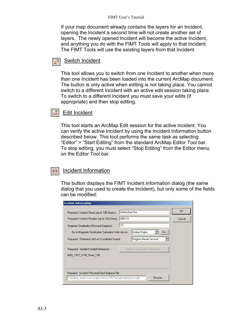
Incident Information This button displays the FIMT Incident information dialog (the same dialog that you used to create the Incident), but only some of the fields can be modified:
AI-3
FIMT User’s Tutorial
You can change the name, the Incident number, the magnetic declination, and the default lat/long coordinate format, but you cannot change the spatial reference or the geodatabase file.
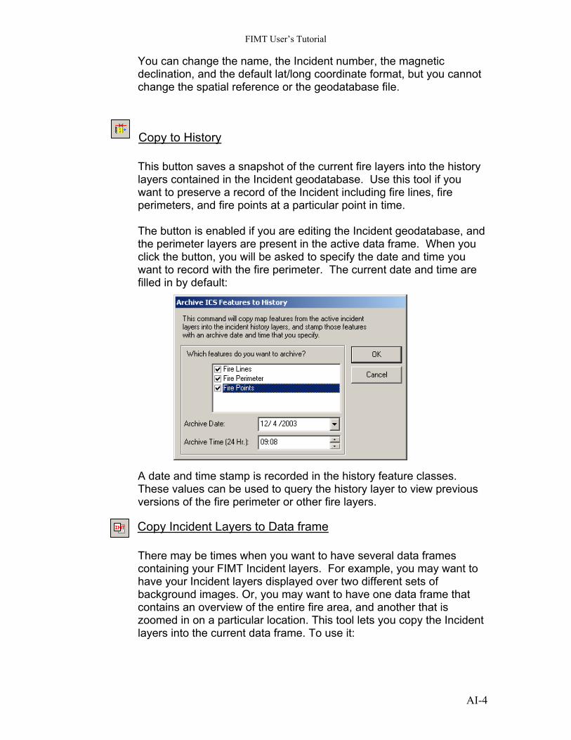
Copy to History This button saves a snapshot of the current fire layers into the history layers contained in the Incident geodatabase. Use this tool if you want to preserve a record of the Incident including fire lines, fire perimeters, and fire points at a particular point in time. The button is enabled if you are editing the Incident geodatabase, and the perimeter layers are present in the active data frame. When you click the button, you will be asked to specify the date and time you want to record with the fire perimeter. The current date and time are filled in by default:
A date and time stamp is recorded in the history feature classes. These values can be used to query the history layer to view previous versions of the fire perimeter or other fire layers.
Copy Incident Layers to Data frame There may be times when you want to have several data frames containing your FIMT Incident layers. For example, you may want to have your Incident layers displayed over two different sets of background images. Or, you may want to have one data frame that contains an overview of the entire fire area, and another that is zoomed in on a particular location. This tool lets you copy the Incident layers into the current data frame. To use it:
AI-4
FIMT User’s Tutorial
Create a new data frame, using the Insert > Data Frame menu option. Or, select an existing data frame and make it active by right clicking on its name in the table of contents, and selecting Activate from the context menu. Click the Copy FIMT Layers to Data Frame button. The Incident layers will be added to your active data frame.
Export to Shape file This tool creates a set of output shapefiles from the active Incident database. The user specifies the output directory where the files will be written. There is no control over the names of the output shape file names. All of the attribute items that belong to a geodatabase domain will be exported with both the domain code and description text as matching attribute columns.
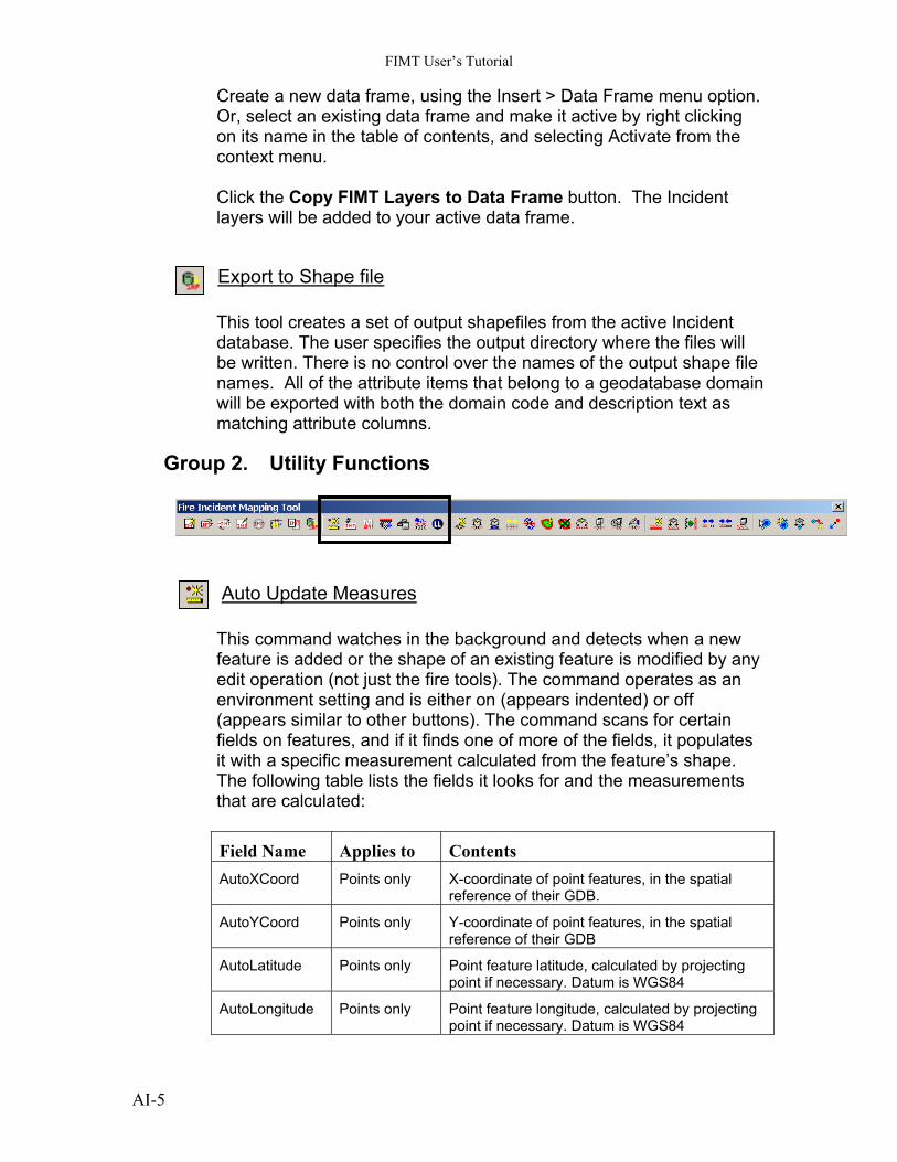
Group 2. Utility Functions
Auto Update Measures This command watches in the background and detects when a new feature is added or the shape of an existing feature is modified by any edit operation (not just the fire tools). The command operates as an environment setting and is either on (appears indented) or off (appears similar to other buttons). The command scans for certain fields on features, and if it finds one of more of the fields, it populates it with a specific measurement calculated from the feature’s shape. The following table lists the fields it looks for and the measurements that are calculated: Field Name Applies to Contents AutoXCoord Points only X-coordinate of point features, in the spatial
reference of their GDB.
AutoYCoord Points only Y-coordinate of point features, in the spatial reference of their GDB
AutoLatitude Points only Point feature latitude, calculated by projecting point if necessary. Datum is WGS84
AutoLongitude Points only Point feature longitude, calculated by projecting point if necessary. Datum is WGS84
AI-5
FIMT User’s Tutorial
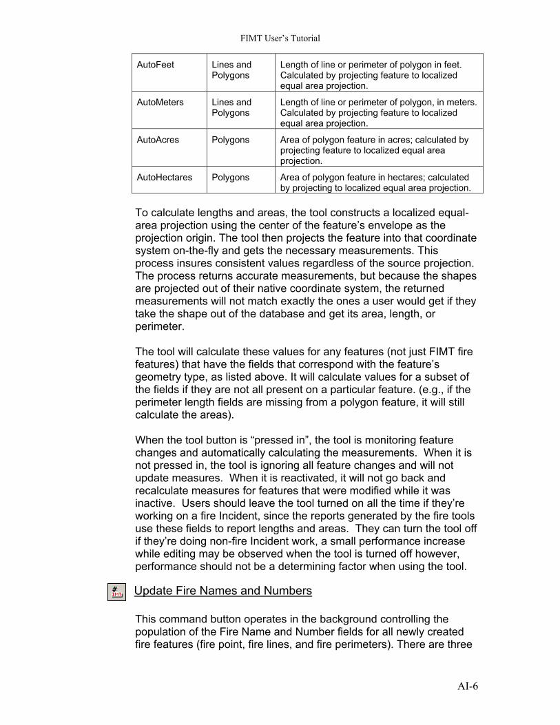
AutoFeet Lines and Polygons
Length of line or perimeter of polygon in feet. Calculated by projecting feature to localized equal area projection.
AutoMeters Lines and Polygons
Length of line or perimeter of polygon, in meters. Calculated by projecting feature to localized equal area projection.
AutoAcres Polygons Area of polygon feature in acres; calculated by projecting feature to localized equal area projection.
AutoHectares Polygons Area of polygon feature in hectares; calculated by projecting to localized equal area projection.
To calculate lengths and areas, the tool constructs a localized equal-area projection using the center of the feature’s envelope as the projection origin. The tool then projects the feature into that coordinate system on-the-fly and gets the necessary measurements. This process insures consistent values regardless of the source projection. The process returns accurate measurements, but because the shapes are projected out of their native coordinate system, the returned measurements will not match exactly the ones a user would get if they take the shape out of the database and get its area, length, or perimeter. The tool will calculate these values for any features (not just FIMT fire features) that have the fields that correspond with the feature’s geometry type, as listed above. It will calculate values for a subset of the fields if they are not all present on a particular feature. (e.g., if the perimeter length fields are missing from a polygon feature, it will still calculate the areas). When the tool button is “pressed in”, the tool is monitoring feature changes and automatically calculating the measurements. When it is not pressed in, the tool is ignoring all feature changes and will not update measures. When it is reactivated, it will not go back and recalculate measures for features that were modified while it was inactive. Users should leave the tool turned on all the time if they’re working on a fire Incident, since the reports generated by the fire tools use these fields to report lengths and areas. They can turn the tool off if they’re doing non-fire Incident work, a small performance increase while editing may be observed when the tool is turned off however, performance should not be a determining factor when using the tool.
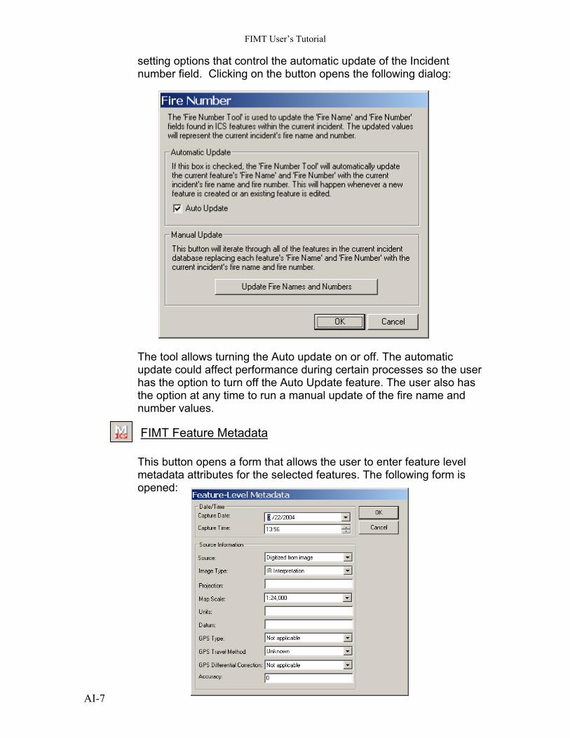
Update Fire Names and Numbers This command button operates in the background controlling the population of the Fire Name and Number fields for all newly created fire features (fire point, fire lines, and fire perimeters). There are three
AI-6
FIMT User’s Tutorial
setting options that control the automatic update of the Incident number field. Clicking on the button opens the following dialog:
The tool allows turning the Auto update on or off. The automatic update could affect performance during certain processes so the user has the option to turn off the Auto Update feature. The user also has the option at any time to run a manual update of the fire name and number values.
FIMT Feature Metadata This button opens a form that allows the user to enter feature level metadata attributes for the selected features. The following form is opened:
AI-7
FIMT User’s Tutorial
All of the attribute fields that contain a list of valid values appear with a pull down list on the form. The remaining fields are free form text field. The user must know their local data standards to input the appropriate values.
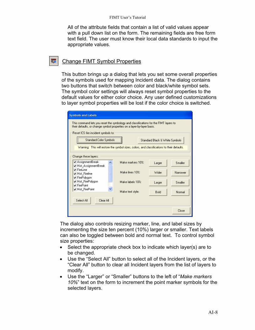
Change FIMT Symbol Properties This button brings up a dialog that lets you set some overall properties of the symbols used for mapping Incident data. The dialog contains two buttons that switch between color and black/white symbol sets. The symbol color settings will always reset symbol properties to the default values for either color choice. Any user defined customizations to layer symbol properties will be lost if the color choice is switched.
The dialog also controls resizing marker, line, and label sizes by incrementing the size ten percent (10%) larger or smaller. Text labels can also be toggled between bold and normal text. To control symbol size properties: • Select the appropriate check box to indicate which layer(s) are to
be changed. • Use the “Select All” button to select all of the Incident layers, or the
“Clear All” button to clear all Incident layers from the list of layers to modify.
• Use the “Larger” or “Smaller” buttons to the left of “Make markers 10%” text on the form to increment the point marker symbols for the selected layers.
AI-8
FIMT User’s Tutorial
• Use the “Larger” or “Smaller” buttons to the left of “Make lines 10%” text on the form to increment the line symbol width for the selected layers.
• Use the “Larger” or “Smaller” buttons to the left of “Make labels 10%” text on the form to increment the size of text labels for the selected layers.
• Use the “Bold” or “Normal” buttons to the left of “Make text style” text on the form to switch text labels between bold and normal text.
• Click “Close” to close the dialog. Note: Changes made using the form are applied immediately and can be undone by applying the opposite operations.
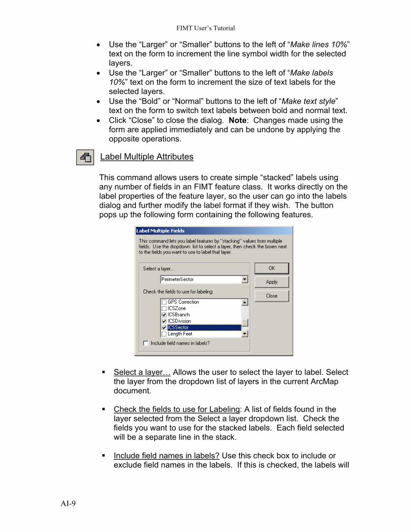
Label Multiple Attributes This command allows users to create simple “stacked” labels using any number of fields in an FIMT feature class. It works directly on the label properties of the feature layer, so the user can go into the labels dialog and further modify the label format if they wish. The button pops up the following form containing the following features. Select a layer… Allows the user to select the layer to label. Select
the layer from the dropdown list of layers in the current ArcMap document.
Check the fields to use for Labeling: A list of fields found in the
layer selected from the Select a layer dropdown list. Check the fields you want to use for the stacked labels. Each field selected will be a separate line in the stack.
Include field names in labels? Use this check box to include or
exclude field names in the labels. If this is checked, the labels will
AI-9
FIMT User’s Tutorial
look like “Fieldname = Value”. If it’s not checked, only the values will be shown.
OK button to keep the settings and closes the form. Use this
when you want to modify just one feature class.
Apply button to create the labels for the selected feature class but leaves the form open so you can set up labels for another feature class.
Cancel button to close the form without applying the current
settings. Any settings you applied with the “Apply” button will still be in effect and will not be undone by the Cancel button.
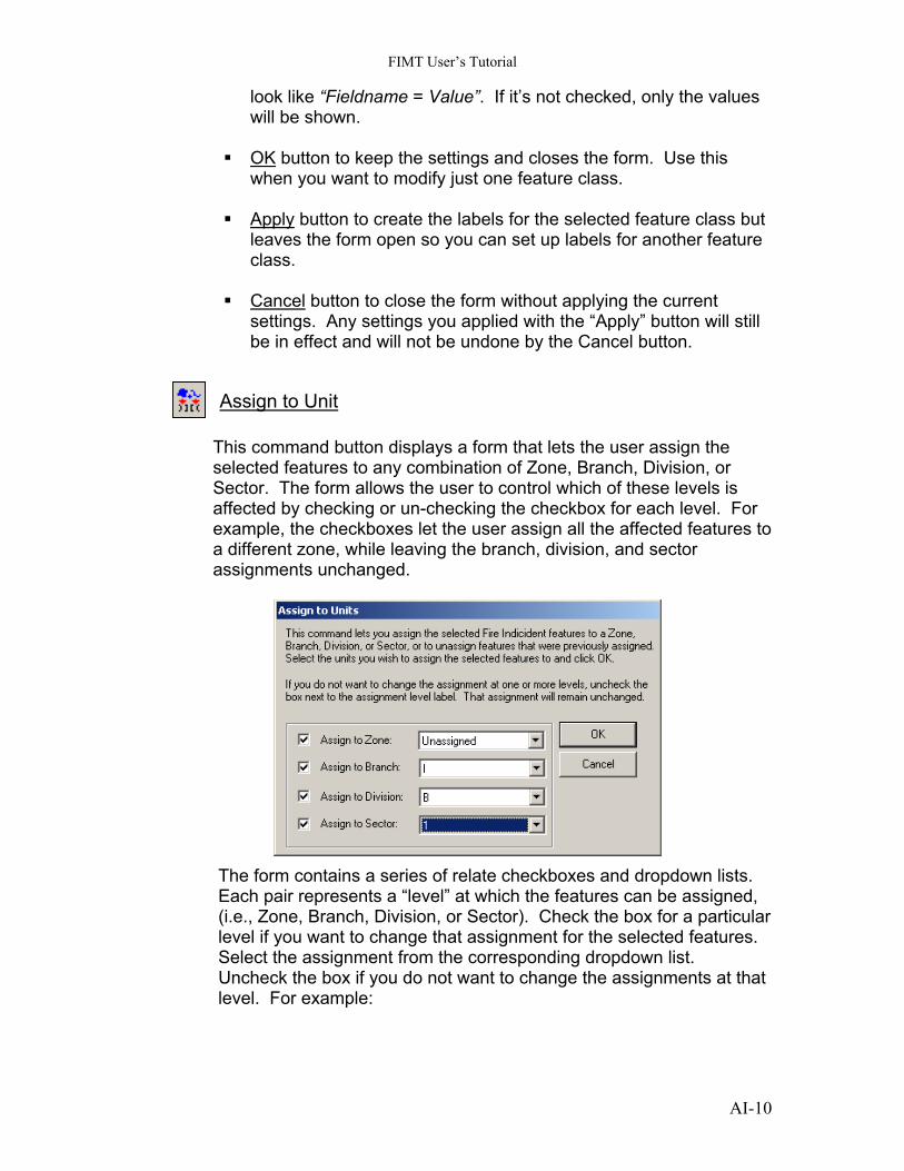
Assign to Unit
This command button displays a form that lets the user assign the selected features to any combination of Zone, Branch, Division, or Sector. The form allows the user to control which of these levels is affected by checking or un-checking the checkbox for each level. For example, the checkboxes let the user assign all the affected features to a different zone, while leaving the branch, division, and sector assignments unchanged. The form contains a series of relate checkboxes and dropdown lists. Each pair represents a “level” at which the features can be assigned, (i.e., Zone, Branch, Division, or Sector). Check the box for a particular level if you want to change that assignment for the selected features. Select the assignment from the corresponding dropdown list. Uncheck the box if you do not want to change the assignments at that level. For example:
AI-10
FIMT User’s Tutorial
To reassign all the features to a particular zone, but keep the lower level assignments the same, check the zone box, uncheck the remaining boxes, and select a zone from the dropdown list. To change just the sector assignment for a feature, uncheck all but the sector box, and select a sector. The feature(s) will remain in the same zone, branch, and division, but will be reassigned to a new sector. Press the OK button to apply the settings. Press the Cancel button to close the form without applying the settings.
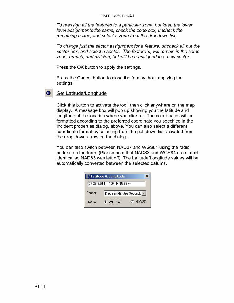
Get Latitude/Longitude Click this button to activate the tool, then click anywhere on the map display. A message box will pop up showing you the latitude and longitude of the location where you clicked. The coordinates will be formatted according to the preferred coordinate you specified in the Incident properties dialog, above. You can also select a different coordinate format by selecting from the pull down list activated from the drop down arrow on the dialog. You can also switch between NAD27 and WGS84 using the radio buttons on the form. (Please note that NAD83 and WGS84 are almost identical so NAD83 was left off). The Latitude/Longitude values will be automatically converted between the selected datums.
AI-11
FIMT User’s Tutorial
Group 3. Perimeter Tools
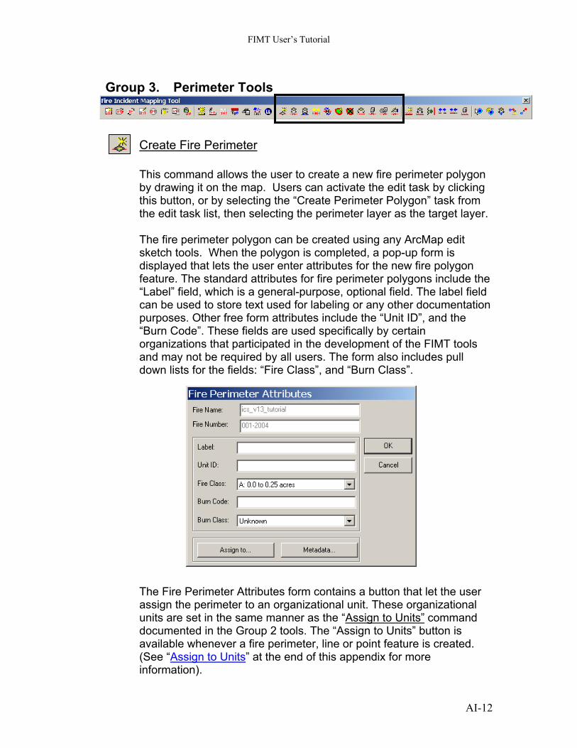
Create Fire Perimeter This command allows the user to create a new fire perimeter polygon by drawing it on the map. Users can activate the edit task by clicking this button, or by selecting the “Create Perimeter Polygon” task from the edit task list, then selecting the perimeter layer as the target layer. The fire perimeter polygon can be created using any ArcMap edit sketch tools. When the polygon is completed, a pop-up form is displayed that lets the user enter attributes for the new fire polygon feature. The standard attributes for fire perimeter polygons include the “Label” field, which is a general-purpose, optional field. The label field can be used to store text used for labeling or any other documentation purposes. Other free form attributes include the “Unit ID”, and the “Burn Code”. These fields are used specifically by certain organizations that participated in the development of the FIMT tools and may not be required by all users. The form also includes pull down lists for the fields: “Fire Class”, and “Burn Class”.
The Fire Perimeter Attributes form contains a button that let the user assign the perimeter to an organizational unit. These organizational units are set in the same manner as the “Assign to Units” command documented in the Group 2 tools. The “Assign to Units” button is available whenever a fire perimeter, line or point feature is created. (See “Assign to Units” at the end of this appendix for more information).
AI-12
FIMT User’s Tutorial
The Fire Perimeter Attributes form contains another button that lets the user enter feature-level metadata describing the source of the fire perimeter polygon feature and the date and time it was collected (See “Feature Level Metadata” at the end of this appendix). Both the unit assignment data and the feature-level metadata are optional as far as the application is concerned.
Every time a fire perimeter feature is created, a corresponding “sector line” feature is also created. The Sector lines are stored in the Incident PerimeterSector feature class. The sector line feature is used to manage the assignment of portions of the perimeter to different operational units. The management of the lines contained in the PerimeterSector feature class is transparent to the user. The user should not perform any direct editing interaction with lines in the PerimeterSector feature class except splitting the lines into two or more pieces. In fact, the FIMT Tools application is designed to prevent the user from changing the geometry of a sector line if it is associated with a perimeter polygon. The application also synchronizes the shape of the sector line with changes to the shape of the perimeter polygon, so it remains coincident in spite of moving, modifying, or reshaping the perimeter polygon.
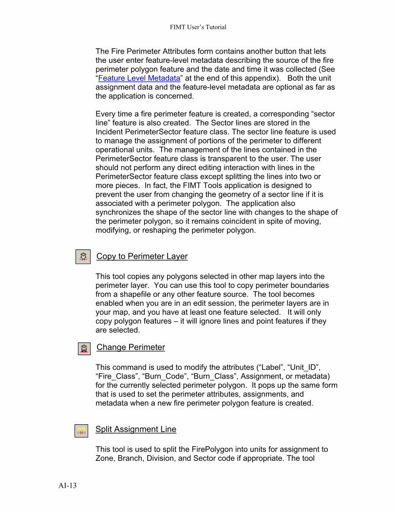
Copy to Perimeter Layer This tool copies any polygons selected in other map layers into the perimeter layer. You can use this tool to copy perimeter boundaries from a shapefile or any other feature source. The tool becomes enabled when you are in an edit session, the perimeter layers are in your map, and you have at least one feature selected. It will only copy polygon features – it will ignore lines and point features if they are selected.
Change Perimeter This command is used to modify the attributes (“Label”, “Unit_ID”, “Fire_Class”, “Burn_Code”, “Burn_Class”, Assignment, or metadata) for the currently selected perimeter polygon. It pops up the same form that is used to set the perimeter attributes, assignments, and metadata when a new fire perimeter polygon feature is created.
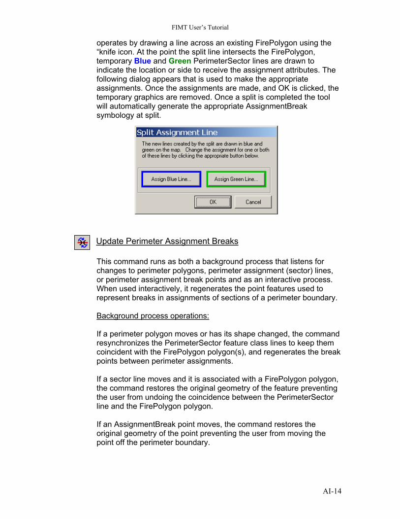
Split Assignment Line This tool is used to split the FirePolygon into units for assignment to Zone, Branch, Division, and Sector code if appropriate. The tool
AI-13
FIMT User’s Tutorial
operates by drawing a line across an existing FirePolygon using the “knife icon. At the point the split line intersects the FirePolygon, temporary Blue and Green PerimeterSector lines are drawn to indicate the location or side to receive the assignment attributes. The following dialog appears that is used to make the appropriate assignments. Once the assignments are made, and OK is clicked, the temporary graphics are removed. Once a split is completed the tool will automatically generate the appropriate AssignmentBreak symbology at split.
Update Perimeter Assignment Breaks This command runs as both a background process that listens for changes to perimeter polygons, perimeter assignment (sector) lines, or perimeter assignment break points and as an interactive process. When used interactively, it regenerates the point features used to represent breaks in assignments of sections of a perimeter boundary. Background process operations: If a perimeter polygon moves or has its shape changed, the command resynchronizes the PerimeterSector feature class lines to keep them coincident with the FirePolygon polygon(s), and regenerates the break points between perimeter assignments. If a sector line moves and it is associated with a FirePolygon polygon, the command restores the original geometry of the feature preventing the user from undoing the coincidence between the PerimeterSector line and the FirePolygon polygon. If an AssignmentBreak point moves, the command restores the original geometry of the point preventing the user from moving the point off the perimeter boundary.
AI-14
FIMT User’s Tutorial
NOTE: Users can create PerimeterSector lines and/or AssignmentBreak points that are not associated with a FirePolygon polygon by simply creating features in these classes. Those features will not be affected by this command. Interactive Process operations: The user may modify the assignments of the PerimeterSector lines associated with a FirePolygon polygon by selecting them and using the “Assign to Unit” command, by editing the attributes directly, or other means in ArcMap. When manual edits are performed, the AssignmentBreak points between unit assignments may no longer be accurate. When the button is clicked, ArcMap will re-evaluate the junctions between all PerimeterSector lines, merge any adjacent lines that have the same assignments breaks, regenerate break points at the new line ends, and set the rotation angle of those points to match the orientation of the lines. Perimeter lines and break points the user has added directly that are not associated with a perimeter polygon are not affected by this command.
Create Island This tool is used to create island or (donut) polygons inside an existing FirePolygon. The tool activates the FIMT Create Island edit task on the FirePolygon target feature class. No other ArcMap editing tools should be used to create island polygons. Due to the complexity of the relationships between FirePolygon, PerimeterSector, and AssignmentBreak feature classes, unpredictable behavior could be encountered. Once the Create Island tool is invoked, any valid ArcMap drawing tool can be used to create the actual geometry of the island. This included using the sketch tool or the trace tool to trace existing features selected in other layers.
Remove Island This tool is used to remove island polygons from an existing FirePolygon. This tool is the only method that should be used to remove or delete island polygons. Do not use any other ArcMap methods. The tool operates by deleting all island geometry that are contained completely inside a temporary polygon drawn by the user. Draw a bounding box around the island you would like to remove.
AI-15
FIMT User’s Tutorial
An error message will be displayed if the polygon is drawn outside the outer boundary of the FirePolygon or if the island polygon intersects the polygon.
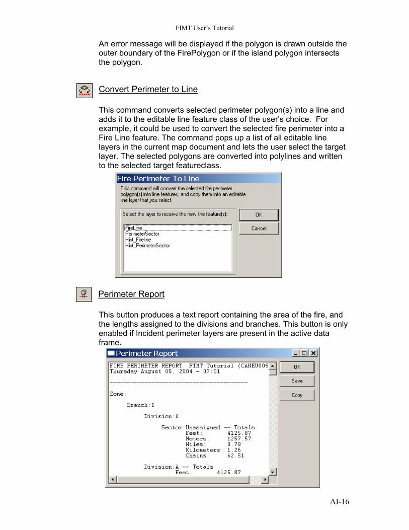
Convert Perimeter to Line This command converts selected perimeter polygon(s) into a line and adds it to the editable line feature class of the user’s choice. For example, it could be used to convert the selected fire perimeter into a Fire Line feature. The command pops up a list of all editable line layers in the current map document and lets the user select the target layer. The selected polygons are converted into polylines and written to the selected target featureclass.
Perimeter Report This button produces a text report containing the area of the fire, and the lengths assigned to the divisions and branches. This button is only enabled if Incident perimeter layers are present in the active data frame.
AI-16
FIMT User’s Tutorial
The Copy button on the Perimeter Report dialog is used to copy the text contents to your Windows clipboard. The text can then be pasted into other applications or pasted into a map layout.
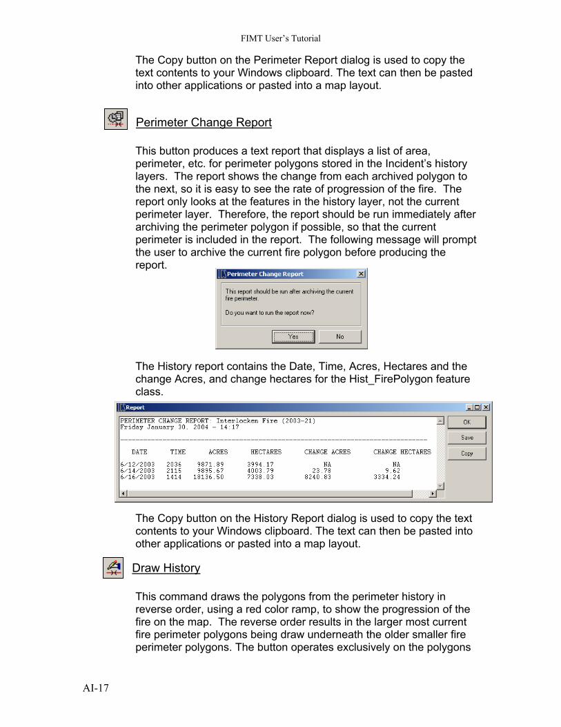
Perimeter Change Report This button produces a text report that displays a list of area, perimeter, etc. for perimeter polygons stored in the Incident’s history layers. The report shows the change from each archived polygon to the next, so it is easy to see the rate of progression of the fire. The report only looks at the features in the history layer, not the current perimeter layer. Therefore, the report should be run immediately after archiving the perimeter polygon if possible, so that the current perimeter is included in the report. The following message will prompt the user to archive the current fire polygon before producing the report.
The History report contains the Date, Time, Acres, Hectares and the change Acres, and change hectares for the Hist_FirePolygon feature class. The Copy button on the History Report dialog is used to copy the text contents to your Windows clipboard. The text can then be pasted into other applications or pasted into a map layout.
Draw History This command draws the polygons from the perimeter history in reverse order, using a red color ramp, to show the progression of the fire on the map. The reverse order results in the larger most current fire perimeter polygons being draw underneath the older smaller fire perimeter polygons. The button operates exclusively on the polygons
AI-17
FIMT User’s Tutorial
from the fire perimeter history layer (Hist_FirePolygon feature class). The “Copy Incident to History” button should be used prior to drawing the history to insure that the most current perimeter is included in the display.
Group 4. Fire Line Tools
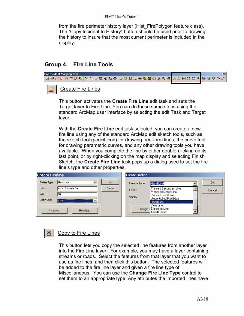
Create Fire Lines This button activates the Create Fire Line edit task and sets the Target layer to Fire Line. You can do these same steps using the standard ArcMap user interface by selecting the edit Task and Target layer. With the Create Fire Line edit task selected, you can create a new fire line using any of the standard ArcMap edit sketch tools, such as the sketch tool (pencil icon) for drawing free-form lines, the curve tool for drawing parametric curves, and any other drawing tools you have available. When you complete the line by either double-clicking on its last point, or by right-clicking on the map display and selecting Finish Sketch, the Create Fire Line task pops up a dialog used to set the fire line’s type and other properties.
Copy to Fire Lines This button lets you copy the selected line features from another layer into the Fire Line layer. For example, you may have a layer containing streams or roads. Select the features from that layer that you want to use as fire lines, and then click this button. The selected features will be added to the fire line layer and given a fire line type of Miscellaneous. You can use the Change Fire Line Type control to set them to an appropriate type. Any attributes the imported lines have
AI-18
FIMT User’s Tutorial
in common with the fire line feature class will also be copied. Lines copied from another incident will retain their type, etc. This control only copies line features. Any selected polygon or point features are ignored.
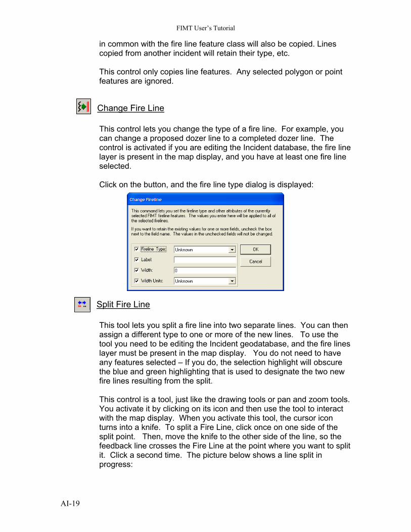
Change Fire Line This control lets you change the type of a fire line. For example, you can change a proposed dozer line to a completed dozer line. The control is activated if you are editing the Incident database, the fire line layer is present in the map display, and you have at least one fire line selected. Click on the button, and the fire line type dialog is displayed:
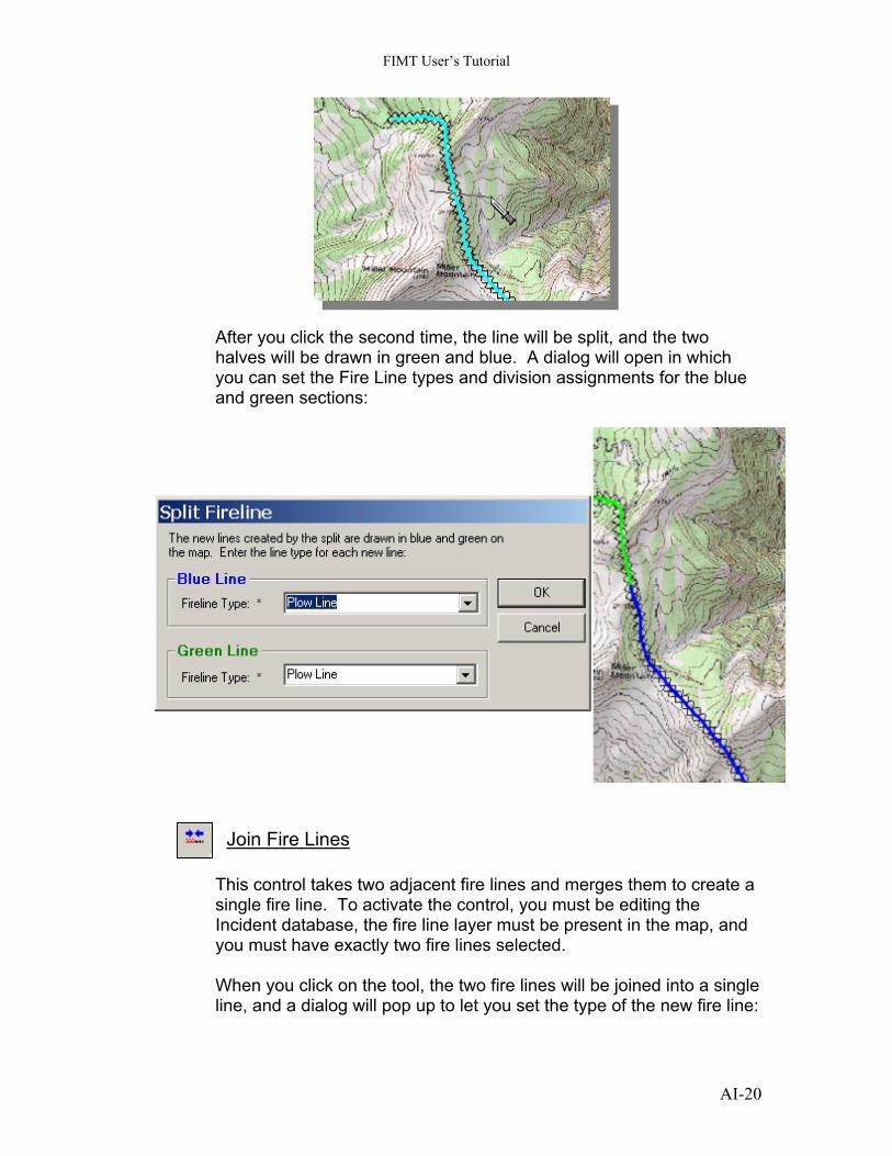
Split Fire Line This tool lets you split a fire line into two separate lines. You can then assign a different type to one or more of the new lines. To use the tool you need to be editing the Incident geodatabase, and the fire lines layer must be present in the map display. You do not need to have any features selected – If you do, the selection highlight will obscure the blue and green highlighting that is used to designate the two new fire lines resulting from the split. This control is a tool, just like the drawing tools or pan and zoom tools. You activate it by clicking on its icon and then use the tool to interact with the map display. When you activate this tool, the cursor icon turns into a knife. To split a Fire Line, click once on one side of the split point. Then, move the knife to the other side of the line, so the feedback line crosses the Fire Line at the point where you want to split it. Click a second time. The picture below shows a line split in progress:
AI-19
FIMT User’s Tutorial
After you click the second time, the line will be split, and the two halves will be drawn in green and blue. A dialog will open in which you can set the Fire Line types and division assignments for the blue and green sections:
Join Fire Lines This control takes two adjacent fire lines and merges them to create a single fire line. To activate the control, you must be editing the Incident database, the fire line layer must be present in the map, and you must have exactly two fire lines selected. When you click on the tool, the two fire lines will be joined into a single line, and a dialog will pop up to let you set the type of the new fire line:
AI-20
FIMT User’s Tutorial
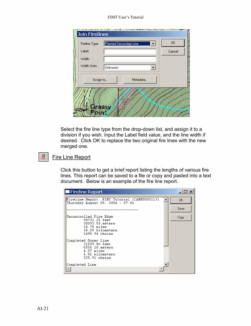
Select the fire line type from the drop-down list, and assign it to a division if you wish. Input the Label field value, and the line width if desired. Click OK to replace the two original fire lines with the new merged one.
Fire Line Report
Click this button to get a brief report listing the lengths of various fire lines. This report can be saved to a file or copy and pasted into a text document. Below is an example of the fire line report.
AI-21
FIMT User’s Tutorial
The Copy button on the Fire Line Report dialog is used to copy the text contents to your Windows clipboard. The text can then be pasted into other applications or pasted into a map layout.
Group 5. Fire Point Tools
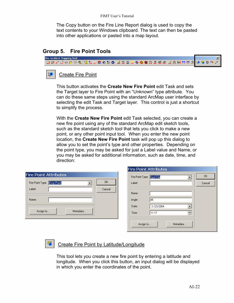
Create Fire Point This button activates the Create New Fire Point edit Task and sets the Target layer to Fire Point with an “Unknown” type attribute. You can do these same steps using the standard ArcMap user interface by selecting the edit Task and Target layer. This control is just a shortcut to simplify the process. With the Create New Fire Point edit Task selected, you can create a new fire point using any of the standard ArcMap edit sketch tools, such as the standard sketch tool that lets you click to make a new point, or any other point input tool. When you enter the new point location, the Create New Fire Point task will pop up this dialog to allow you to set the point’s type and other properties. Depending on the point type, you may be asked for just a Label value and Name, or you may be asked for additional information, such as date, time, and direction:
Create Fire Point by Latitude/Longitude This tool lets you create a new fire point by entering a latitude and longitude. When you click this button, an input dialog will be displayed in which you enter the coordinates of the point.
AI-22
FIMT User’s Tutorial
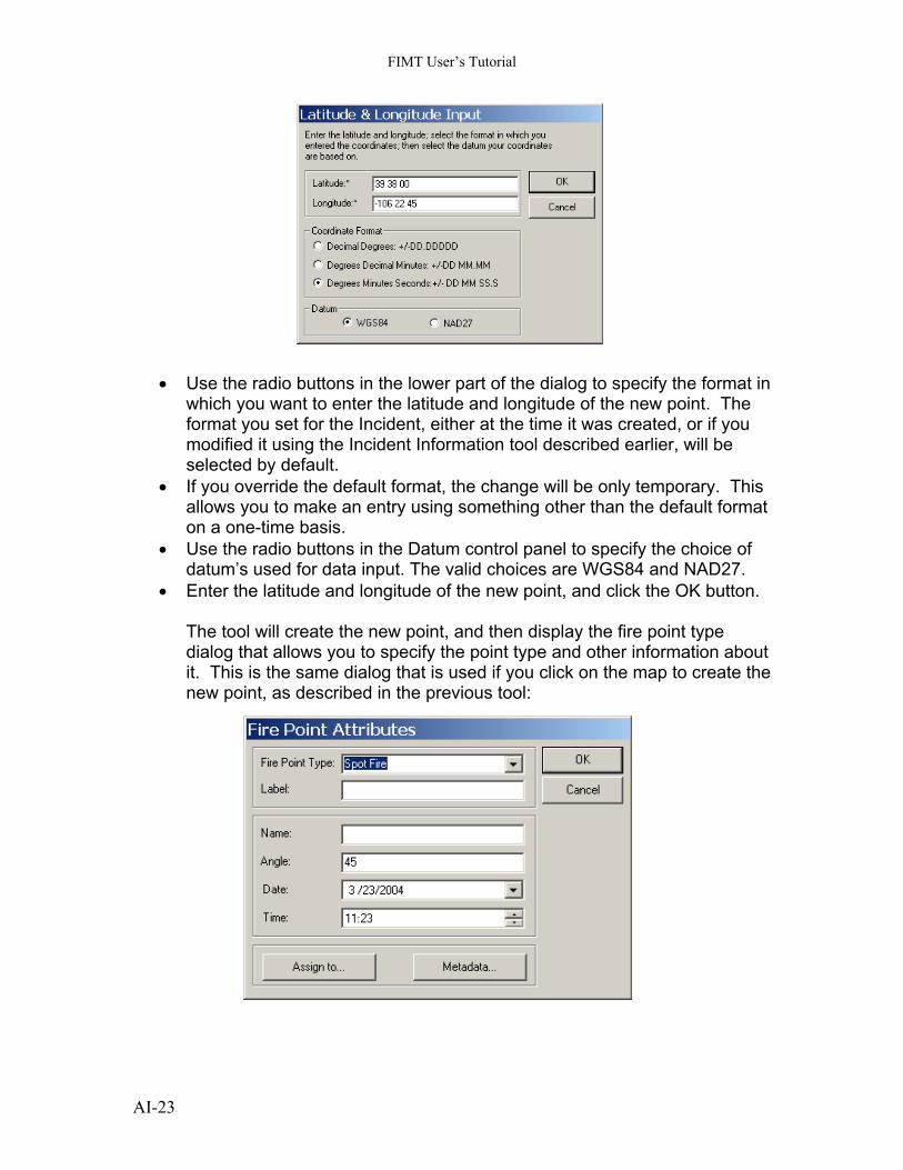
• Use the radio buttons in the lower part of the dialog to specify the format in which you want to enter the latitude and longitude of the new point. The format you set for the Incident, either at the time it was created, or if you modified it using the Incident Information tool described earlier, will be selected by default.
• If you override the default format, the change will be only temporary. This allows you to make an entry using something other than the default format on a one-time basis.
• Use the radio buttons in the Datum control panel to specify the choice of datum’s used for data input. The valid choices are WGS84 and NAD27.
• Enter the latitude and longitude of the new point, and click the OK button.
The tool will create the new point, and then display the fire point type dialog that allows you to specify the point type and other information about it. This is the same dialog that is used if you click on the map to create the new point, as described in the previous tool:
AI-23
FIMT User’s Tutorial
Copy to Fire Points
int
n a fire
that have matching attributes will retain eir original attribute values.
s point features. Any selected polygon or line features are ignored.
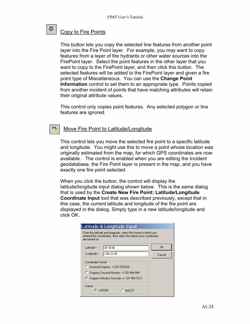
Move Fire Point to Latitude/Longitude
This button lets you copy the selected line features from another polayer into the Fire Point layer. For example, you may want to copy features from a layer of fire hydrants or other water sources into the FirePoint layer. Select the point features in the other layer that youwant to copy to the FirePoint layer, and then click this button. The selected features will be added to the FirePoint layer and givepoint type of Miscellaneous. You can use the Change Point Information control to set them to an appropriate type. Points copied from another incident of pointsth This control only copie
is present in the map, and you have xactly one fire point selected.
og
t in
in the dialog. Simply type in a new latitude/longitude and lick OK.
This control lets you move the selected fire point to a specific latitude and longitude. You might use this to move a point whose location was originally estimated from the map, for which GPS coordinates are nowavailable. The control is enabled when you are editing the Incident geodatabase, the Fire Point layere When you click the button, the control will display the latitude/longitude input dialog shown below. This is the same dialthat is used by the Create New Fire Point: Latitude/Longitude Coordinate Input tool that was described previously, except thathis case, the current latitude and longitude of the fire point are displayed c
AI-24
FIMT User’s Tutorial
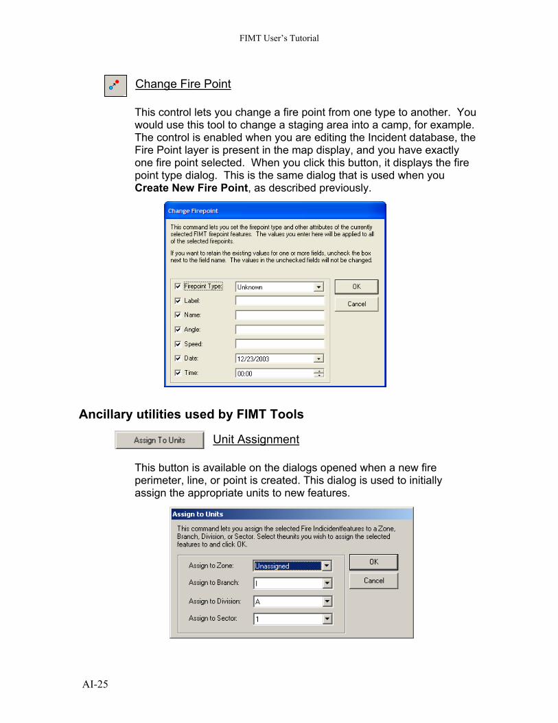
Change Fire Point This control lets you change a fire point from one type to another. Ywould use this tool to change a staging area into a camp, for exampleThe control is enabled when you are editing the Incident database, Fire Point layer is present in the map display, and you have exactly one fire point selected. When you click this button, it display
ou .
the
s the fire oint type dialog. This is the same dialog that is used when you reate New Fire Point, as described previously.
Ancillary utilities used
pC
by FIMT Tools
Unit Assignment This button is available on the dialogs opened when a new fire
erimeter, line, or point is created. This dialog is used to initially ssign the appropriate units to new features.
pa
AI-25
FIMT User’s Tutorial
AI-26
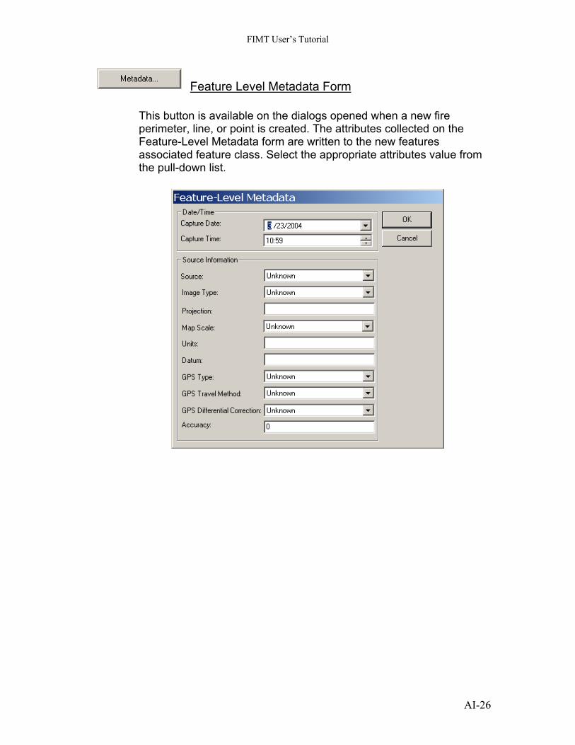
Feature Level Metadata Form
the
class. Select the appropriate attributes value from e pull-down list.
This button is available on the dialogs opened when a new fire perimeter, line, or point is created. The attributes collected onFeature-Level Metadata form are written to the new features associated featureth


![[Arcgis] Riset ArcGIS JS & Flex](https://img.pdfslide.us/doc/110x75/55cf96d7550346d0338e2017/arcgis-riset-arcgis-js-flex.jpg)