Embed Size (px)
Citation preview
OPTICAL WINDOWS
William P. Barnes
Precision Optics Corporation 22 East Broadway
Gardner, Massachusetts 01440-3338
/ ABSTRACT
In the context of this review, an optical window is a solid barrier with a principal function of transmitting some portion of the electromagnetic spectrum between the short wave atmospheric cutoff of 180 nanometer wavelength and the 12 micrometer thermal infrared. ' Uses range from protection of optical instruments against hostile natural environments to containment of exceptional man-made environments for study (e.g., combustion) or for production of special forms of energy (e.g., lasers). Flat, uniform thickness panels are most common. Spherical segments and conical elements have found use. Other curved elements and multiple flat glazings are often used to better conform to the shape of a vehicle or other enclosure.
Application of such barriers requires that we examine the effects, other than the desired unimpeded and
- undistorted transmission, which may be introduced.
1. INTRODUCTION
Perhaps "optical window" doesn't need the above definition. We are surrounded by windows. However, an unabridged dictionary has nine definitions, my (somewhat ancient) Britannica limits itself to the architectural fenestration definition, and Van Nostrand's Scientific Encyclopedia, Sixth Edition, completely ignores the word. Thus, I have taken advantage of this window of opportunity.
The insertion of a solid barrier for protection of an optical system, or isolation of an object or process, may introduce several potential penalties including:
a) reduced transmission resulting from the reflect ion, absorption, and scatter of the window material, b) contrast reduction caused by lack of control of the reflected and scattered energy, c) further increase in scatter or reduction of transmission by environmental effects such as erosion or radiation darkening,
Optornechanical besign / 233
d) addition of wavefront aberrations characteristic of the window shape, the window area in use, and positioning of the associated imaging system, e) further aberrations induced in the window by the mechanical and thermal environments, f) even absent the above, a possible significant restriction of the field of view, and, g) the possibi 1 ity of catastrophic fai lure.
My objective is to provide a review of some such penalties for several window configurations, and mounting methods. No claim is made for completeness. I attempt to provide some calculation procedures which may assist in judging whether a particular effect is important or to determine that finite element or other digital solutions are yielding reasonable results. The specification of units and numerical values is left, for the most part, to the other articles of this volume.
In critical applications the window behavior will require more precise study which then should be included as an integral part of the lens design analyses.
2. WINDOW CONFIGURATIONS
2.1. Flat Panes
The most common window is a single flat sheet of transmitting material. If perfectly flat and perfectly optically homogeneous, it adds no aberrations to subsequent imaging of an object at infinity, but it may limit the field of view. For close objects, a focal shift and other aberrations may be added to subsequent imagery. Accelerations, pressure differentials, other mechanical forces and thermal perturbations will affect both surface flatness and optical homogeneity.
Where the window replaces a shaped and otherwise opaque structure, or to increase the available field of view, multiple flat glazings may be used. These may approximate a curved surface without introducing the aberrations of a curved optical element. It is noted that small aberrations are sometimes tolerated for aesthetic or aerodynamic reasons- when is the last time you saw completely flat automobile windshield glazings?
2.2. Spherical Domes
A near hemisphere is an natural shape for a wide field scanning system such as the acquisition and tracking optics of a self guided missile. It also provides a substantial
234 / Critical Reviews Vol. CR43
mechanical strength advantage in applications subjected to large pressure differentials, such as deep submergence vehicles. Some aspects of these particular applications are considered in more detail in subsequent sections.
2.3. Conformal Shapes
For a supersonic or hypersonic missile, considerations of shock wave aerodynamics may suggest a preference for a true cone rather than a spherical dome as the forward facing element. Cylindrical segments may be recommended for other locations in high speed vehicles. One possibility has been treated in detail by Gearhartl.
3. FLAT WINDOWS
3.1. Reflect ion and Absorption
The presence of a window will affect both the amp1 itude and phase of the useful wavefronts it is designed to transmit. Useful energy may be removed by reflection from the window surfaces, by absorption in the bulk material and at times by mechanisms which can be described only as poorly understood "surface absorption", and by scattering, again as both a bulk and surface phenomenon. A penalty arises less from the loss of energy than from the ultimate disposition of the "lost" energy.
For small values of bulk absorption and at normal incidence, the fraction of incident energy reflected at each surface is given by the usual Fresnel relation for an index of refraction, n, as [(n-l)/(n+1)12. Moderate values of bulk absorption are well characterized by an exponential decay of intensity, I, equal to exp(-Bz) in the thickness direction. Bulk scattering is often included (intentionally or otherwise) in the I3 coefficient. Ignoring multiple reflections, the single pass transmittance of the window, 1/10, then may be calculated as:
For non-normal incidence, the variation of reflectance with incident polarization becomes important at incidence angles of 30 or more. In materials with large values of refractive index and with surfaces not precisely para1 lel , multiple reflect ions may also affect subsequent imagery or instrumentation. Of course, anti-reflection coatings can substantially mitigate all the reflection effects.
Optornechanical Design / 235
3.2. Window Bending Ef fec ts
Consider a thin, nominally flat, window of an initially homogeneous and isotropic material. Transverse forces or temperature gradients through the thickness cause the window to bend. Within the limits of thin plate theory, the bending stresses vary linearly through the thickness and average to zero. For normally incident rays, the possible optical effects resulting from thickness change (via Poisson's ratio) , and of stress induced refractive index change and birefringence are, at least theoretically, zero. Perceptible effects on optical path differences and on distortion in the imagery of sensors following the window may occur for large incidence angles or in wide field imagery when the stress pattern varies rapidly over the plan dimensions of the window. Such cases are respectable challenges for the best current ray-tracing programs, and will not be pursued here.
Bending alone, however, does introduce an optical path difference, even for small deflections, as a result cf the the local slope of the deflected element. For circularly symmetric cases, the OPD was estimated by Sparks and Cottisz, and applied to pressure bending by Sparks and by Klein~. The derivation did not include the effect of refraction at the first surface. If we include the refraction (for a surrounding index of 1.0), and generalize to the case for which the deflection, w, is a function of both plan coordinates, the optical path difference, OPD, may be shown to be:
OPD = [(N-1) h/2~]*[(6w/6x)~ + (6w/6~)~]. N is the window index of refraction and h its thickness, with 6 used here to denote partial differentiation. With this expression as our principal tool, we can explore several cases of bending by transverse loads. and axial temperature gradients.
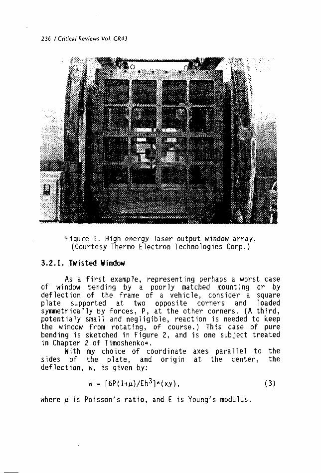
Let us note that windows of precisely circular plan form are quite uncommon. Pressure and vacuum vessel viewports are often circular because gipe flanges are circular. Some lasers use circular output windows, but many, such as the high energy device shown in Figure 1, use other shapes and multiple glazings to resist substantial pressure pulses. Reconnaissance applications, FLIR systems, passenger aircraft and cruise ships all use a variety of elliptical, square, rectangular or trapezoidal plan forms.
236 / Critical Reviews Vol. CR43
Figure 1. High energy laser output window array. (Courtesy Thermo Electron Technologies Corp. )
3.2.1. Twisted Window
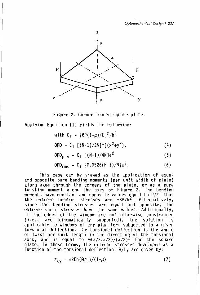
As a first example, representing perhaps a worst case of window bending by a poorly matched mounting or by deflection of the frame of a vehicle, consider a square plate supported at two opposite corners and loaded symmetrically by forces, P, at the other corners. (A third, potentialy small and negligible, reaction is needed to keep the window from rotating, of course.) This case of pure bending is sketched in Figure 2, and is one subject treated in Chapter 2 of Timoshenkoa.
With my choice of coordinate axes parallel to the sides of the plate, and origin at the center, the deflection, w, is given by:
where f i is Poisson's ratio, and E is Young's modulus.
Optomechanical Design / 237
Figure 2. Corner loaded square plate.
Applyi~g Equation (1) yields the following:
2 5 with C1 = [6P(ltp)/E] /h
2 2 OPD = C1 [(N-1)/2N]*[(x ty ) , (4)
This case can be viewed as the application of equal and opposite pure bending moments (per unit width of plate) along axes through the corners of the plate, or as a pure twisting moment along the axes of Figure 2. The bending moments have constant and opposite values qua1 to P/2, thus 9 the extreme bending stresses are +3P/h . Alternatively, since the bending stresses are equal and opposite, the extreme shear stresses have the same values. Additionally, if the edges of the window are not otherwise constrained (i e . , are kinematically supported), the solution is applicable to windows of any plan form subjected to a given torsional deflection. The torsion21 deflection is the angle of twist per unit length in the directio of the torsional axis, and is equal to w(a/2,~1/2)/(a/2)~ for the square plate. In these terms, the extreme stresses developed as a function of the torsional deflection, 0/L, are given by:
238 1 Critical Reviews Vol. CR43
For final emphasis on this case, we note that the optical path difference introduced is (again, small deflections) a purely spherical change in the wavefront, the same effect as a purely spherical deflection.
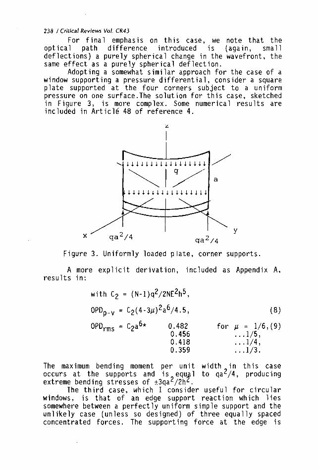
Adopting a somewhat similar approach for the case of a window supporting a pressure differential, consider a square plate supported at the four corners subject to a uniform pressure on one surface.The solution for this case, sketched in Figure 3, is more complex. Some numerical results are included in Art icl6 48 of reference 4.
Figure 3. Uniformly loaded plate, corner supports.
A more explicit derivation, included as Appendix A , results in:
with C2 = ( ~ - 1 ) ~ ~ / 2 N ~ ~ h ~ ,
O P D ~ ~ ~ = c2a6* 0.482 for p = 1/6,(9) 0.456 . . .1/5,
The maximum bending moment per unit width in this case occurs at the supports and is equ 1 to qa2/4, producing ! extreme bending stresses of +3cqa2/2h .
The third case, which I consider useful for circular windows, is that of an edge support reaction which lies somewhere between a perfectly uniform simple support and the unlikely case (unless so designed) of three equally spaced concentrated forces. The supporting force at the edge is
Optornechanical Design / 239
p o s t u l a t e d t o vary as ( l t c o s ( 3 8 ) ) . For a p l a t e o f r a d i u s b, and suppo r t i ng f o r c e o f (qb/2) ( l t c o s ( 3 B ) ) , the d e f l e c t i o n ,w, may be shown t o be:
The a lgebra i s l e s s daun t ing i f one chooses a va lue f o r p , and notes t h a t t h e maximum va lue o f t h e s lope should occur a t t h e edge. For p = 0.3, and r = b, t h e s lope components are:
S w / G r = ( q b 3 / ~ h 3 ) [ 1 .05+0.460 cos(3B) I and,
The OPD i s a maximum a t 8 = 0; f o r p l a t e d iameter D:
Except f o r t h e a d d i t i o n a l N i n t h e denominator, t h i s i s t w i c e t h e r e s u l t shown b y Klein. f o r a u n i f o r m edge suppor t .
As a f o u r t h case, we cons ide r an a x i a l temperature g r a d i e n t which i s un i f o rm over t h e p l a n dimensions o f t h e window. The window d e f l e c t i o n i s a p u r e l y s p h e r i c a l change, and i s independent o f t h e p l a n f o rm as i n t h e f i r s t case above. For a s teady s t a t e hea t f l u x pe r u n i t area, F, through t h e window, a l i n e a r a x i a l temperature dependence, i s developed, and t he OPD may be ob ta ined by s u b s t i t u t i n g :
f o r C1 i n Equat ions 4 , 5, and 6 . Here a i s t h e c o e f f i c i e n t o f therma l expansion, k t h e thermal c o n d u c t i v i t y , and AT t h e temperature d i f f e r e n t i a l across t h e window.
Of ten, f o r unsteady s t a t e cases, t h e thermal s t r a i n may be expressed as a power s e r i e s i n t h e t h i ckness dimension:
Then, n o t i n g t h a t arT = Ccm t h e c a l c u l a t i o n o f t h e cu rva tu re change may be rearrang:!'as:
240 1 Critical Reviews Vol. CR43
1/R = (l/h)Cc,[l-(m-1) (m-2)/((m+l) (m+2))]
and then expanded to:
Thus, unless the,higher terms in the power series are quite large, the deflections and optical path differences may be closely approximated using the total temperature difference alone.
3.3. Lateral Temperature Gradients
It is normally necessary to both support and seal a window at the entire edge, thus providing a heat conduction path. Aerodynamic heating, the absorption of part of a high power transmitted beam, or other radiation to or from the window will develop lateral ten~perature gradients. The circularly symmetric lateral gradient case in which the temperature distribution replicates the intensity distribution in a high power laser is treated by Klein5 in terms of the effect on the Strehl ratio of the focussed beam. The derivation may be put in the form of the following optical path differences for the average over polarization of the incident beam and for the birefringent OPD:
where T is measured as the temperature increase from the center of the window, and T' is the area weighted average temperature increase between the center and the radial position ,r,or:
T' = (2/r2) T r'dr'. I q and qs are the piezooptic constants for, in this case, an i ! otropic material and stresses parallel and perpendicular (senkrecht) to the polarization of the incident beam. Klein treats the "short time approximation" case which neglects the thermal diffusion of the energy absorbed from a high power beam, but is important to assessment of the performance of high power, pulsed laser systems.
Optomechanical Design 1 24 1
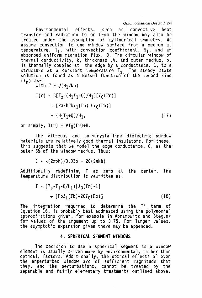
Environmental effects, such as convective heat transfer and radiation to or from the window may also be treated under the assumption of cyl indrical symmetry. We assume convection to one window surface from a medium at temperature, TI, with convection coefficient, H1, and an absorbed uniform radiation flux, Q. The circular window of thermal conductivity, k, thickness ,h, and outer radius, b, is thermally coupled at the edge by a conductance, C, to a structure at a constant temperature Ts The steady state solution is found as a Bessel function 'of the second kind (In) ass:
with r = J(Hl/kh)
or simply, T(r) = AIO(rr)+B.
The vitreous and polycrystall ine dielectric window materials are relatively good thermal insulators. For these, this suggests that we model the edge conductance, C, as the outer 5% of the window radius. Thus:
Additionally redefining T as zero at the center, the temperature distribution is rewritten as:
The integration required to determine the T' term of Equation 16, is probably best addressed using the polynomial approxi~iiat ions given, for example in Abramowi tz and Stegun7 for values of the argument up to 3.75. For larger values, the asymptotic expansion given there m/ay be appended.
4. SPHERICAL SEGMENT WINDOWS
The decision to use a spherical segment as a window element is usually driven more by environmental, rather than optical, factors. Additionally, the optical effects of even the unperturbed window are of sufficient magnitude that they, and the perturbations, cannot be treated by the separable and fairly elementary treatments out 1 ined above.
242 / Critical Reviews Vol. CR43
Analysis of the basic elastic, temperature, and thermal stress effects of the environment is also made more complex by the spherical boundary conditions. For example, in high speed missile domes of near hemispherical configuration, the pressure differential and rate of heat transfer will vary significantly over the surface of the dome.
One application treated in some optical detail in the past is that of underwater viewports. A (two volume and appendix) design report was prepared by the U.S.Navy Ocean Systems Centers and a portion reproduced for an SPIE symposium by Lonesg. The presence of water (index 1.33) reduces the optical effect of the outer surface by a factor of 3 for the acrylic viewports considered. With flat windows, the effect is to make objects appear nearer, the "bent stick" effect. The spherical window is a much stronger negative lens than when air is present on both sides. Its effects on the apparent object distance, distortion and binocular viewing are reported in some detail. A complete underwater imaging system, the E. Leitz Canada "C201 ELCAN Water Contact Lens" is discussed by McNeillo.
Kleinll reviews the design criteria for shallow domes of CVD diamond as might be applied in supersonic or hypersonic missile guidance. (Flat windows for high power lasers are also treated.) Much of the current thrust in development of materials, processes, and application evaluation is reviewed in the SPIE symposia proceedings Window and Dome Technoloqies and Materials,Volume 1112 (1989), and Window and Dome Technoloqies and Materials 11, Volume 1326 (1990).
5 . SURVIVABILITY
5.1. Fracture
From a practical point of view, all of the window materials are brittle. Their failure mode, under constant load, may proceed from the slow growth of cracks (from flaws initially present) to a critical size at which the crack then grows rapidly. For glasses, the location of susceptible flaws is normally at the surface. For polycrystalline materials, such flaws may exist throughout the bulk. Single crystal materials may also be susceptible to cleavage along particular planes, with this form of damage being caused at times by only moderate thermal shock.
The relationship between crack size, crack orientation, and applied macroscopic stress has been the subject of considerable study. A large body of literature exists on this subject, and on the similar slow crack growth behavior of ductile materials under cyclic loading. Scanning
Optornechanical Design 1 243
of a recent issue of "Mechanics", a title citation pub1 icat ion of the American Academy of Mechanics, reveals the following journals devoted to this technology:
Engineering Fracture Mechanics, Fatigue and Fracture of Engineering Materials
and Structures, International Journal of Fatigue, and International Journal of Fracture.
In the same issue, related papers are included in the European Journal of Mechanics A Solids, and the International Journal of Engineering Science.
I can only provide a glimpse of this technology, abstracted from reference 1 2 .
For glasses, the velocity of propagation of a crack has been shown to depend on crack dimension, L, and transverse tensile stress, a, combined in a stress intensity factor, KI, as:
K = aJ(nL). The value of t his factor when catastrophic failure occurs is the critical stress intensity factor, KIc. Crack velocity and KI data for several glasses were reported by Wiederhorn and BOFZ~., and a straight line correlation of the logarithm of crack velocity versus KI reported. Representative values are those for fused silica (Corning 7940):
For these correlations, the time to failure, tf at constant stress may be expressed as:
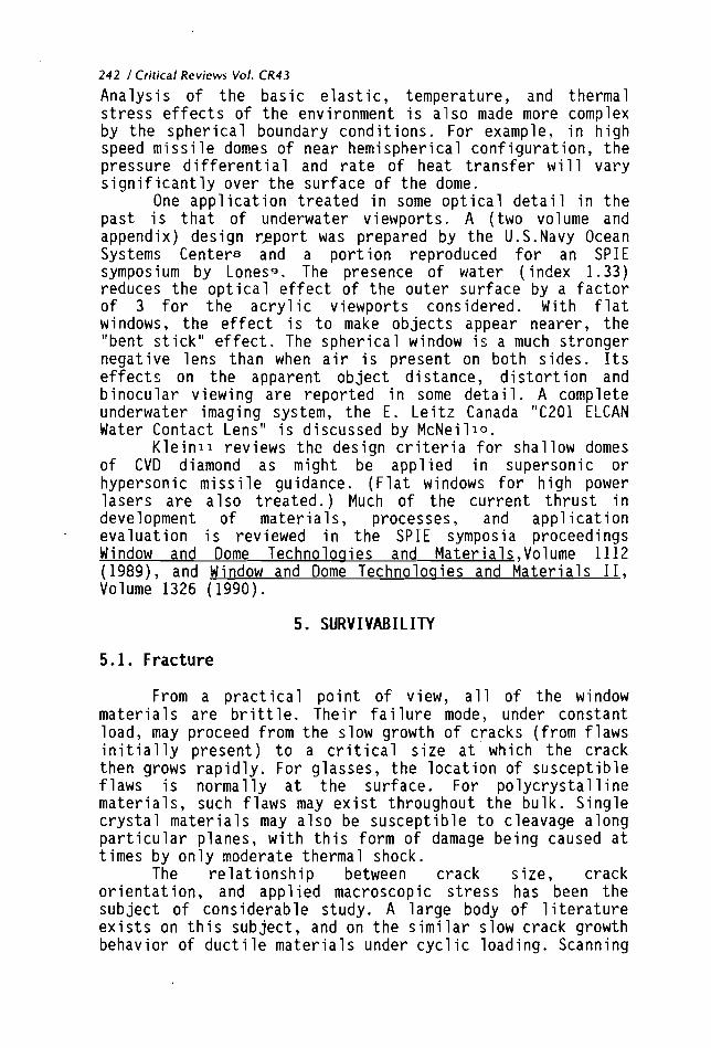
The results of this calculation for fused silica as presented in reference 12 are reproduced in Figure 4.
A more recent communicationl4,' cites a study15 of the effect of residual stress introduced with the initial flaw by indentation. The principal effect appears to be a reduction in the critical flaw size by a factor of four, or reduction in the value of KIc by a factor of two.
These and similar data must be handled with great care. In any practical situation, the presence, size, orientation and spatial distribution of initial flaws will be poorly defined. Additional flaws will be introduced in
244 / Critical Reviews Vol. CR43
handling and exposure. Finally, the applied stress will be constant neither in space nor time.
7,000
. 6,000 \5 .. 0 ", 5,000 -- . -- --
VI u /
Zi 4,000 - - 0.003-in. flaw
d
"7 C
e u 3,000 : w
1 h r 1 day l week 30 90 days 1 yr 3 yr
1,000 I i I I I I I L lo1 10' l o5 lo6 lo7 loR
Figure 4. Time to tailure at constant stress for fused silica.
5.2. Stress Analysis
The stress levels noted in Section 2 for cases of pure - bendirlg do not account for any edge or localized support
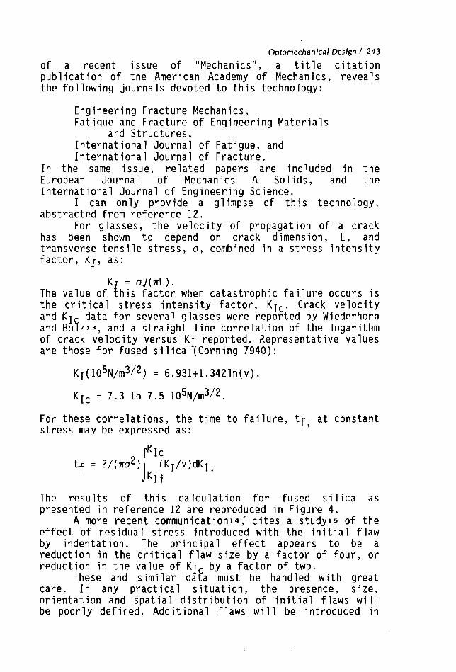
reaction stresses. The same is true for the solutions for spherical domes i n textbooks such as Timoshenko. That recourse to a careful finite element analysis should often be taken is illustrated for a shallow shell by Orringer and Tong16. For the design sketched in Figure 5, (Figure 19b of Ref. 16) constant thickness shell theory indicates that only compressive stresses will exist.
Figure 5. A shallow shell window.
Optomechanical Design 1 245
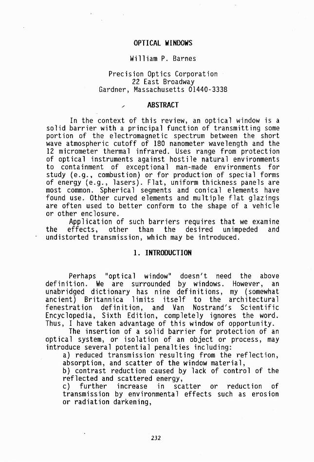
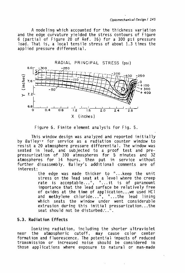
A modeling which accounted for the thickness variation and the edge curvature yielded the stress contours of Figure 6 (partial of Figure 20 of Ref. 16) for a 300 psi pressure load. That is, a local tensile stress of about 1 . 3 times the applied pressure differential.
R A D I A L P R I N C I P A L STRESS (psi )
0 0.4 0.8 1.2 1.6 2 .0 2.4 2.8
X ( inches)
Figure 6. Finite element analysis for Fig. 5.
This window design was analyzed and reported initially by Bailey17 for service as a radiation counter window to resist a 20 atmosphere pressure differential. The window was seated in lead, and subjected to a proof test and pre- pressurization of 100 atmospheres for 5 minutes and 32 atmospheres for 14 hours, then put in service without further disassembly. Bailey's additional comments are of interest:
the edge was made thicker to "...keep the unit stress on the lead seat at a level where the creep rate is acceptable...", "...it is of paramount importance that the lead surface be relatively free of oxides at the time of application ... we used HC1 and methylene chloride...", "...the lead lining which seats the window under went considerable extrusion during this initial pressurization . . . the seat should not be disturbed.'..".
5.3. Radiation Effects
Ionizing radiation, including the shorter ultraviolet near the atmospheric cutoff, may cause color center formation and fluorescence. The potential impacts of reduced transmission or increased noise should be considered in those appl icat ions where exposure to natural or man-made
246 l Critical Reviews Vol. CR43
radiations exceeds that of our everyday environment. Even long term exposure to normal solar radiation may cause darkening- for example, special UV grades of polymethyl methacrylate are available the resist this effect. Cerium doping of optical glasses has also been shown to be effective in improving resistance to radiation darkening. Color centers also may be bleached by subsequent heat treatment 16.
High dose rqies of high energy electrons have been known to result i n electron discharge damage (Lichtenberg f igureslg) . High radiation doses may also induce density, and thus refractiveindex, changeszo.
A useful phenomenological and historical survey of radiation effects in glass is the paper by Sun and Kreidlzl. The effect of cerium on several glasses is detailed by Kreidl and Henslerzz. Pellicori et al.23, provides a collection of transmission loss data for a number of window glasses, filter glasses, crystals, and transmitting fibers in the 400 to 900 nm wavelength region.
5.4. Impact Erosion
In our 1975 Handbooklz, we included a very brief review of the data then available. In part:
"Data on impact erosion by solids (dust erosion) have been presented by Sheldon (Ref.24 here). In these data there is no evidence of an incubation period or a threshold velocity. For brittle materials the volume of material removed (W) given by W = klraVb is in reasonable agreement with experiment. Here r is the radius of the impacting particle and V its velocity. The other parameters, which may dependon the statistics of the flaw distribution in the materi 1 i acted, approach the values a-3, b-2.4, k EO.~/O? where E is Young's modulus and o is related to the failure strength of the materia?."
I have not, at this point, pursued later citations of the Sheldon24 work.
The investigation of water droplet impact at high subsonic and supersonic speeds has continued apace, however. A substantial body of literature exists, and study of the current state of the technology might best begin with the papers of Session 5 of SPIE Proceedings Volume 1326, working backward if necessary. To set the framework, I quote from Adler and Boland25:
"The mechanics of single waterdrop impact is fairly we1 1 understood (Adler, 1979b). The waterdrop contacts the surface and the contact area between
Optornechanical Design 1 247
the drop and the surface expands as the square root of the time. The loading cycle is relatively short: on the order of a tenth of a microsecond. A critical condition is reached where the pressure at the surface is catastrophically released. The magnitude of the pressure and the loading period generate the transient stresses in the target material which are directly responsible for the primary damage produced in the target. The unique feature of the waterdrop impact is the precipitous demise of the drop during the loading cycle."
This proceedings includes complementary papers on coatings for erosion protection and reflectance reduction. Continuing development of diamond-like coatings (and perhaps free standing diamond windows) offers future promise.
6. MATERIALS
In any discussion of materials, one is tempted to generate a nearly all inclusive listing of all conceivably useful materials and their important (and sometimes their obscure) properties. I have easi ly resisted that temptation because such an at once useful and compact tabulation has been accomplished by Wolfez6. A more detailed collection of- optical property data is provided by Weberz7. The AIPze and OSA29 Handbooks are also valuable sources of data. Optical "constant" data for a range of wavelengths well beyond the scope I attempt to cover here may be found in the two volumes edited by palik30y31. Weast32, and other scientific and engineering handbooks are occasionally useful. Manufacturers' data is of particular value when you get into the nitty-gritty of hardware, and is indispensable for setting the final specifications and property certifications needed.
Some comments here on the materials suitable for certain wavelength ranges may be helpful.
6.1. 180 to 400 nanometer wavelengths
The alkali halides have limited value because of their solubility in water. The alkaline Carth halides are much less soluble but subject to cleavage on (111) planes. Some recently developed fluoride based glasses are useful in the upper end of this wavelength range. Synthetic fused silica transmits well throughout, fused natural quartz exhibits reduced transmission below 250 to 220 nanometers.Both sapphire and magnesium fluoride are quite transparent but birefringent.
248 / Critical Reviews Vol. CR43
The principal practical candidate materials for windows (and lenses) are calcium fluoride and synthetic fused silica.
6 .2 . 400 to 2500 nanometer wavelengths
Almost everything labelled an optical material transmits in some part or all of this wavelength range. Ordinary soda-limp window glass cuts out some of the blue and red, and thus looks green when viewed edge-on. A number of optical glasses have been formulated for reduced sensitivity to optical path change with temperature (with zero stress change), i .e. reduced values of [dN/dT+a(N-1)] (see Section 3.3 above). It is worth noting that, although the a of fused silica is small, dN/dT is larger than, for example, BK-7 glass, and the optical path change with temperature cannot be assumed to be small.
Above 550 nanometers, zinc sulfide and zinc selenide "cut-on", and the transparent regions of silicon and germanium begin at about 1+ and 2+ micrometers respectively.
6.2 . 2 .5 to 3 micrometer wavelength
Materials synthesized or processed at high temperatures in the strict absence of water may transmit we11 in this region. Others, such as flame-fusion synthesized fused silica have strong 0-H absorption bands in this region. Special processing, and the electrical fusion of natural quartz can produce transparent silicas, however.
6.3. 3 to 5 micrometer wavelengths
The transparency of the alkaline earth halides and sapphire extends to this region. Calcium aluminate and germanate glasses are also useful here, as is arsenic trisulf ide (rather soft, however). Most of the materials used in the 8 to 12 micrometer region are also transparent here, though some may scatter more than desired. In general, oxide glasses are not recommended at these and longer wavelengths.
6 .4 . 3 to 12 micrometer wavelengths
The transparency of si 1 icon decl ines significantly beyond 5.5+ micrometers, and zinc sulfide has a moderate absorption band near 6 micrometers. The alkal i ha1 ides are transparent throughout and beyond this region (cesium iodide to about 50 micrometers). The calcogenide glasses (GeSeSb
Optomechanical Design / 249
and GeSeAs), thallium bromide/iodide (soft), zinc sulfide, zinc selenide, and germanium may all find application.
Here it is of interest to note the development of a zinc sulf ide/zinc selenide laminated window material33 which takes advantage of the better erosion resistance of zinc sulfide and the better transparency to 12-14 micrometers od zinc selenide. Practical application has been made in the U.S.Air Force LANTIRN (Low Altitude Navigation and Targeting InfraRed system for Night) program. Klein3 treats the flexural stress distribution which develops assuming zero stress as the zinc sulfide is *deposited on a thicker zinc selenide substrate at about 650 Celsius. He also derives an expression for the window transmission in terms of the reflectance of the three interfaces and the material absorption coefficients and thicknesses.
Two additional effects of the laminated construction may be of concern in some applications. First, interfacial shear and normal tensile stresses are developed at window edges by the differential expansion. These may be estimated from a closed form solution published by Suhir.4. Pionke and Wempner35 point out that neither the Suhir solution nor finite element calculations can account for the 1 ikel ihood of a stress singularity right at the edge. They also note, however that this singularity can be avoided by bevelling .
the individual layers away from the interface at the edges (suggested by Professor S.Lukasiewicz, University of Calgary). I'm not sure this discussion is ended.
Secondly, the refractive indices of the materials are different. Thus, if one first prepares a polished flat substrate of zinc selenide, deposits zinc sulfide, cools, and then refinishes the now curved outer surfaces to flat, one is left with a more or less spherical interface and a window with some optical power.
ACKNOWLEDGMENTS
I have attempted to acknowledge some of those who have contributed to my education by citing what I hope are the more useful recent references and other sources of data. I 'm sure there remain many others whose particular contributions are locked in my subconscious. f
250 / Critical Reviews Vol. CR43
7 . APPENDIX A
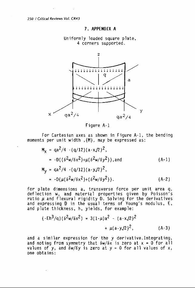
Uniformly loaded square plate, 4 corners supported.
2
For Cartesian axes as shown in Figure A-1, the bending moments per unit width ,(M), may be expressed as:
for plate dimensions a, transverse force per unit area q, deflection w, and material properties given by Poisson's ratio p and flexural rigidity D. Solving for the derivatives and expressing D in the usual terms of Young's modulus, E, and plate thickness, h, yields, for example:
and a simi lar expression for the y derivative. Integrating, and noting from symmetry that 6w/6x is zero at x = 0 for all values of y, and 6w/6y is zero at y = 0 for all values of x, one obtains:
More algebra then provides the following maximum value (at the corners of the plate) for the optical path difference factor:
Even more algebra results in an rms value for this slope factor given by:
Some numerical values for the total optical path difference coefficients are tabulated in the body of the paper.
8. REFERENCES
1. Scott A. Gearhart, "Image degradations of an aerodynamically shaped optical window", Johns Hopkins APL Tech. Digest, 12, 1, 81-85, 1991.
2. M.Sparks and M.Cott is, "Pressure- induced optical distortion in laser windows", J.Appl.Phys., 44, 2, 787-794, Feb. 1973.-
3. Claude A. Klein, "ZnS, ZnSe, and ZnS/ZnSe windows: their impact on FLIR system performance", Opt. Eng. 25, 519- 531, April 1986.
4. S .Tinioshenko, and S.Woinowsky-Krieger, Theory of Plates and Shells, 2nd Edition, McGraw-Hill, 1959.
5. Claude A. Klein, "Optical distortion coefficients of high power laser windows", Opt. Eng. 29, 343-350, April 1990. N
6. W.P.Barnes, "Some effects of the aerospace thermal environment on high-acuity optical systems", APPLIED OPTICS, 5, 5, 701-711, May 1966.
7. M.Abramowitz and I.E.Stegun, Eds., Handbook of Mathematical Functions, AMS 55, National Bureau of Standards, Tenth Print inq, December 1972. -
8. J.D.Stachiw, Acrylic Viewports for Ocean Engineering Apulications, NTIS ADA-070535,-070536,&-070537.

252 l Critical Reviews Vol. CR43
9. Joe J. Lones, "Optical aspects of underwater windows with an overview on mechanical instal lation", Ocean Optics VI, SPIE Vo1.208, 84-123, 1979.
10. Gomer T. McNei1, "Metrical fundamentals of underwater lens system", Opt .Eng. 16, 2, 129-139, Mar./Apr. 1977.
11. Claude A.Klein, "Diamond windows for the infrared: fact and fallacy", Infrared O~tical Desiqn and Fabrication, Rudolf Hartmmn and Warren J.Smith, Eds.,SPIE Volume CR 38, 218-257, 1991.
12. W.P.Barnes, Ed., Reconnaissance and Surveillance Window Design Handbook, AFAL-TR-75-200, October 1975.
13. S.M.Wiederhorn and L.H.Bolz, "Stress corrosion and static fatigue of glass", J.Amer.Ceram.Soc., 53, 543, 1970.
14. R. Nagle, Litton Itek Optical Systems, "Window life test review", Private communication, July 1991.
15. B.L.Symonds, R.F.Cook, and B.R.Lawn, "Dynamic fatigue of brittle materials containing indentation line flaws", J.Matl .Sci . ,l8, 1306-14, 1983.
16. 0.Orringer and P.Tong, "Uses and abuses of the finite element method",SPIE Volume 450, 1983.
17. B.M.Bailey, "Quartz window design for gas- pressurized PMT installation," J.Nuclear Inst.& Methods, 125, 3, 353-355, Apr. 15, 1975.
18. M. J.Treadaway, B.C.Passenheim, and B.D.Kitterer, "Radiation coloring and bleaching of glass", IEEE Transactions on Nuclear Science, NS-23,6,1820-25, December, 1976.
19. G.C.Lichtenberg, Novi. Comment. Gott., 8, 168, 1777.
20. W.Primak, "Dependence of the compaction of vitreous silica on the ionization dose", Nuclear Science and Engineering, 65, 141-196, 1978.
21. Kuan-Han Sun and Norbert J. Kreidl, "Coloration of glass by radiation", in three parts, The Glass Industry, 33,lO- 12, October-November-December, 1952.
22. N.J.Kreid1 and J.R.Hensler, "Gamma radiation insensitive optical glasses", J.Opt. Soc. Am., 47, 1, 73-75, January, 1957.
23. S.F .Pel 1 icori, E. E .Russel 1, and L .A.Watts, "Radiation induced transmission loss in optical materials", APPLIED OPTICS, 18, 15, 2618-21, 1 August,1979.
24. 6.L .Sheldon, "Similarities and differences in the erosion behavior of materials", Trans. ASME, J.Basic Engineering, 92, Ser .D(3), 619-626, Sept. 1970.
25. William F.Adler and Peter L.Boland, "Multiparticle supersonic impact test program", Window and Dome Technoloqies 11, SPIE Volume 1326, 268-279, 1990.
Optomechanical Design 1 253
26. William L.Wolfe, "Optical materials for the infrared", Infrared O D ~ ical Desiqn and Fabricat ion, SPIE Volume CR38, 55-68, 1991.
27. Marvin J.Weber, Ed., Handbook of Laser Science and Technoloqy, Volume IV, Optical Materials: Part 2, CRC Press, Boca Raton, 1986.
28. Dwight E.Gray, Coord. Ed., American Institute of Physics Handbook, McGraw-Hill, 3rd Ed.,1972.
29. Walter G.Driscol1 and William Vaughan, Eds., Handbook of Optics, McGraw-Hill, 1978.
30. Edward D.Palik, Ed., Handbook of Ootical Constants of Solids, Academic Press, 1985.
31. Edward D.Palik, Ed., Handbook of Optical Constants of Solids 11, Academic Press, 1991.
32. Robert C.Weast, Ed., CRC Handbook of Chemistry and Physics, CRC Press, Boca Raton, 61st Ed., 1980.
33. R.Donadio, J.Connolly and J.Pappis, "Sandwich type FLIR windows", AFML-TR-79-4113 (1979).
34. E.Suhir, "Interfacial stresses in bimetal thermostats", J. Appl. Mech.,56, 3, 595-600, 1989.
35. Christopher D.Pionke and Gerald Wempner, "The various approximations of the bimetallic thermostatic strip", J. Appl. Mech., 58, 4, 1015-1020, 1991.