Embed Size (px)
Citation preview

3 4 2
7 9 U
Manuals of British Practicein Water Pollution Control
Unit Processes
SEWAGE SLUDGE I:PRODUCTION, PRELIMINARYTREATMENT AND DIGESTION
The Institute ofWater Pollution ControlLedson House, 53 London Roadf
Maidstone, Kent. ME16 8JH ''"1979 •••••
u r>n

THE INSTITUTE OF WATER POLLUTION CONTROL
MANUALS OF BRITISH PRACTICE IN WATER POLLUTION CONTROL
Sewage Sludge I: Production, Preliminary Treatment and Digestion,
Correction:
Page 82, Appendix 1, Column headed "Dry Matter
In line 2\ delete "2,34"insert " - "

Mesophilic digestion plant and administration block at Ringlcy Fold sewage-treatment works

Manuals of British Practicein Water Pollution Control
Unit Processes
SEWAGE SLUDGE I:
PRODUCTION, PRELIMINARY TREATMENT
AND DIGESTION
The Institute ofWater Pollution Control
1979/ . ' . . • • : • • l i ' - . O

THE INSTITUTE OF WATER POLLUTION CONTROL
President:
G. A. Truesdale, B.Sc, F.I.P.H.E., M.I.W.E.S. (Fellow)
Editorial Sub-Committee:
H. A. Hawkes (Chairman)Isabel M. Lamont (Secretary)M. D. F. Haigh (Co-ordinator and Editor)D. M. BarlowA. M. BruceB. E. ButlerE. I. ClarkC. P. JamesC. E. JonesV. H. LewinN. E. W. SambidgeH. H. Stanbridge (until September 1977)
1979
Price £4-00

P REF ACE
In 1970 the Council of the Institute of Water Pollution Control discussedthe question of the publication of definitive manuals on the subject of BritishPractice in Water Pollution Control and concluded that such publicationswould generally be welcomed.
The Institute's publication An Introduction to Sewage Treatment willcontinue to serve as a general guide to the layman interested in the subject,whilst the manuals will, it is hoped, cover the subject in sufficient depth to becomeaccepted as a reference source both to those already actively engaged in thisparticular field as well as to students seeking authoritative guidance whenpreparing for professional qualifications.
Throughout the manuals of unit processes of waste-water treatment it willbe seen that there is often a variety of equipment available for any particularpurpose, and different modes of operation are described. Wherever possible, anindication is given of circumstances which favour the use of any particulartype of equipment or method of operation which past experience has shown to beadvantageous. The variable nature of sewage and sludge means, however, thatsuch an indication can usually only be given with qualifications.
The preparation of this Manual has included a lot of work on the part of anumber of persons, and the Sub-Committee of the Institute's PublicationsCommittee which has been responsible for its production wish to thank thosemembers of the Council of the Institute who have made comments and sugges-tions for its improvement, and especially do they wish to thank the staff of theWater Research Centre, Stevenage Laboratory.
The initial draft of this manual was first prepared by Mr. H. H. Stanbridge,former editor of the Manuals Sub-Committee; the Sub-Committee wish torecord their appreciation of his efforts in doing so. At the time of his death in1977 the draft was still in an early stage of processing and credit is due toMr. Malcolm D. F. Haigh who took over the duties of co-ordinator and editorat this difficult time.
H. A. Hawkes
Chairman
— 5 —

ACKNOWLEDGMENTS
The Institute wishes to make grateful acknowledgment to the following forpermission to reproduce illustrations:
Mr. G. Ainsworth, Director of Scientific Services, North-West Water Auth-ority (Frontispiece).
Mr. G. T. Calder, Division Director, Southern Division, Yorkshire WaterAuthority (Plates 1 and 5).
Mr. L. H. Thompson, Divisional Manager, Metropolitan Public Health Divi-sion, Thames Water Authority (Plates 6, 7 and 8).
Ames Crosta Babcock Ltd. (Fig. 4 and Plate 1).
Dorr-Oliver Co. Ltd. (Figs. 5 and 8 and Plates 2, 3 and 6).
Jones and Attwood Ltd. (Fig. 9 and Plate 4).
Simon-Hartley Ltd. (Fig. 10 and Plate 5).
— 6

SEWAGE SLUDGE I: PRODUCTION, PRELIMINARYTREATMENT AND DIGESTION
CONTENTS
PREFACE 5
1. SLUDGE PRODUCTION 13
1.1 Introduction 131.2 Sludge production 131.3 Character of sewage sludges 15
1.3.1 Types of sludge 151.3.2 Primary sludge 151.3.3 Secondary sludge 161.3.4 Humus sludge 161.3.5 Surplus activated sludge 161.3.6 Tertiary sludge 161.3.7 Digested sludge 17
1.4 Calculation of sludge quantity (Gravimetric) 171.4.1 Primary sludge 171.4.2 Humus sludge 181.4.3 Surplus activated sludge 19
1.4.3.1 High-rate activated sludge (less than 5h aera-tion) 19
1.4.3.2 Conventional (intermediate-rate) activated sludge(5-16 h aeration) 19
1.4.3.3 Extended-aeration activated sludge (more than20 h aeration) 19
1.4.4 Tertiary sludge 191.4.5 Digested sludge 19
1.5 Calculation of sludge quantity (Volumetric) 191.5.1 Primary sludge 201.5.2 Secondary sludge 201.5.3 Mixed sludge 20
2. PRELIMINARY SLUDGE TREATMENT 21
2.1 Introduction 212.2 Screening 212.3 Sludge thickening/consolidation 21
— 7 —

2.3.1 Purpose 222.3.2 Gravity separation 23
2.3.2.1 Thickening tanks 232.3.2.2 Consolidation tanks 242.3.2.3 Operation and performance of consolidation
and thickening tanks 252.3.3 Gas flotation 26
2.3.3.1 Operation and performance 262.3.3.2 Electrolytic flotation 27
2.3.4 Centrifugation 282.3.4.1 Nozzle bowl or disc-stack centrifuge . . . . 282.3.4.2 Solid bowl, scroll centrifuge 30
3 . AEROBIC DIGESTION OF SEWAGE SLUDGE 33
3.1 Introduction 333.2 Development of process 33
4. ANAEROBIC DIGESTION OF SEWAGE SLUDGE 35
4.1 Introduction 354.2 Microbiology of process 364.3 Biochemistry of process 37
4.3.1 Decomposition of carbohydrates 384.3.2 Decomposition of proteins 384.3.3 Decomposition of fats (lipids) 39
4.4 Preliminary treatment 394.5 Factors affecting anaerobic digestion 40
4.5.1 Composition of raw sludge , 404.5.1.1 Nutrients 404.5.1.2 Secondary sludges 404.5.1.3 Inhibitory substances 40
(i) Heavy metals 41(ii) Halogenated hydrocarbons 41
(iii) Anionic detergents 424.5.2 Method of addition of raw sludge 434.5.3 Mixing and circulation 434.5.4 Temperature 434.5.5 pH value 444.5.6 Solids retention period 44
4.6 Primary digesters 444.6.1 Types 444.6.2 Design criteria 45

4.6.2.1 Digester capacity 454.6.2.2 Organic loading 454.6.2.3 Shape of digester 464.6.2.4 Sludge mixing and circulation 46
(i) Central screw mixing pump 46(ii) Circulating pumps housed in projecting
chambers 48(iii) Internal gas-lift pumps 48
4.6.2.5 Scum removal 494.6.2.6 Grit removal 50
4.6.3 Heating equipment 504.6.3.1 Concentric-tube sludge/hot water heat exchanger 504.6.3.2 Spiral-tube sludge/hot water heat exchanger . . 504.6.3.3 Gas-fired multi-tube heater 51
4.6.4 Covers 514.6.4.1 Fixed covers 514.6.4.2 Floating covers 51
4.6.5 Gasholders 514.6.6 Gas detectors 52
4.6.6.1 Ringrose 524.6.6.2 Spiralarm 534.6.6.3 Combustible gas detectors 534.6.6.4 Automatic gas monitors 53
4.6.7 Monitoring equipment 544.6.8 Pipework 544.6.9 Installations of primary digestion tanks 54
4.7 Secondary digestion (or storage) tanks 544.7.1 Purpose 544.7.2 Design criteria 56
4.7.2.1 Capacity 564.7.2.2 Dimensions 564.7.2.3 Inlets and outlets 564.7.2.4 Scrapers 564.7.2.5 Withdrawal of separated liquor 58
4.7.3 Installations of secondary digestion tanks 584.8 Operation 58
4.8.1 Commissioning procedure 584.8.1.1 Preliminary arrangements 58
(i) Supply of seed sludge 58(ii) Treatment of excess of raw sludge . . . . 58
(iii) Source of heating 584.8.1.2 Methods of commissioning digesters 58
— 9 —

4.8.1.3 Procedure when gasification occurs • 594.8.2 Routine operation 59
4.8.2.1 Frequency of feeding 594.8.2.2 Mixing and circulation 594.8.2.3 Temperature control 604.8.2.4 pH control 604.8.2.5 Withdrawal of sludge 61
4.8.3 Operating difficulties 614.8.3.1 Inhibition of digestion and remedial measures . 61
(i) Heavy metals 62(ii) Halogenated hydrocarbons 63
(iii) Synthetic detergents 634.8.3.2 Stratification 64
(i) Scum formation 64(ii) Grit accumulation 65
4.8.3.3 Foaming 654.8.3.4 Emptying 664.8.3.5 Separation and withdrawal of liquor 66
4.9 Sampling procedures 674.10 Control tests 67
4.10.1 Monitoring of volatile acids and pH value 674.10.2 Monitoring of methane content of sludge gas . . . 684.10.3 Monitoring of toxicity 68
4.11 Maintenance 684.11.1 Lubrication 684.11.2 Covers 69
4.11.2.1 Vacuum and pressure relief assembly . . . 694.11.2.2 Flame traps 694.11.2.3 Level alarm 694.11.2.4 Pipelines 694.11.2.5 Guide rollers and rails 69
4.11.3 Heat exchangers 694.12 Performance '. 69
4.12.1 Reduction of organic matter and dry solids duringdigestion 69
4.12.2 Performance of heated digestion plants 704.12.2.1 Primary digesters 704.12.2.2 Secondary digesters 70
4.13 Digesters at ambient temperature (cold digestion) . . . . 704.13.1 Application 704.13.2 Factors affecting digestion at ambient temperature . 724.13.3 Construction 72
— 10 —

4.13.4 Operation 734.13.5 Performance 74
4.14 Products of anaerobic digestion 744.14.1 Digested sludge 744.14.2 Liquor 74
4.14.2.1 Composition 744.14.2.2 Treatment 75
4.14.3 Sludge gas 754.14.3.1 Composition 754.14.3.2 Calorific value 754.14.3.3 Production 754.14.3.4 Hazards 76
(i) Methane 76(ii) Carbon dioxide 76
(iii) Hydrogen sulphide 764.14.3.5 Precautions 764.14.3.6 Detection 78
5. UTILIZATION OF SLUDGE GAS 79
5.1 Power production 795.1.1 Economics 795.1.2 Dual-fuel engines 80
5.1.2.1 Description 805.1.2.2 Operation 805.1.2.3 Maintenance 805.1.2.4 Performance 81
5.1.3 Other engines running on sludge gas 81Appendix 1. Calculation of Reduction of Organic Matter and Dry
Solids during Digestion 82Appendix 2. Production of Digester Gas (using Buswell's formula) 83
REFERENCES 84
INDEX 88
11 —

PLATES
(Between pages 50 and 51)
1. View of top of Simplex type digester at Aldwarke, Rotherham.2. Primary and secondary digesters at Berry Hill, Bournemouth.
3. Sludge digestion plant incorporating 'limpet' type heat exchangers atDunmurry.
4. Arrangement of 'Burper-mixer' in sludge digester.5. 'Heatamix' units on mesophilic sludge digestion plant at Swinton,
Yorkshire.6. Installation showing gas-fired multi-tube heating units.7. Dual-fuel engines at Hogsmill Valley sewage-treatment works.8. Power house at Croydon's Beddington sewage-treatment works.
FIGURESPage
1. Unit processes and operations employed in treatment, utilizationand disposal of sewage sludge 14
2. Relationship between dry solids content and volume of sludge. . 223. Cross-section of circular sludge consolidation tank 24
4. 'Exploded' view of gas flotation unit 275. 'Exploded' view of nozzle bowl or disc-stack centrifuge 296. Diagrammatic cross-section of solid bowl, scroll centrifuge. . . 307. Primary digestion tank with screw mixing pump and external
heater 478. 'Limpet' type external heat exchanger and sludge circulation unit. 47
9. Arrangement of 'Burper-mixer' sludge circulation plant. . . . 48
10. Principle of'Heatamix'unit 4911. Cross-section of circular'cold'digester 7212. Cross-section of rectangular'cold'digester 73
— 12 —
1. Sludge Production
1.1 Introduction
Sludge is defined1 as being 'a mixture of solids and water produced duringthe treatment of waste water'.
Although the volume of liquid sludge which is produced at a sewage-treatment works usually represents only 1-2 per cent of the total flow ofsewage, its treatment and disposal is generally a major operation accountingfor as much as 50 per cent of the total running costs of the works. The variousstages of treatment to which sludge may be subjected before final disposal,and the alternative forms of disposal, are depicted in Fig. 1. All the stages oftreatment shown are not required in every case and the combination of unitprocesses which are actually employed before disposal will depend upon manyfactors.
The basic objectives of the selection and operation of a sludge treatmentand disposal system are (a) to reduce any potential detrimental effect on theenvironment to an acceptable level, (b) to maximize any beneficial effect, and(c) to achieve these objectives at an acceptable cost. The purpose of sludgetreatment is to render the sludge more amenable to disposal by the variousmethods which are available and to minimize the cost of disposal. Treatmentmay be carried out specifically to achieve one or more of the following aims:
(i) To render the sludge less offensive and reduce any potential hazardto health, e.g. by anaerobic digestion or lime conditioning;
(ii) To convert the sludge to a form which is more suitable for use inagriculture, e.g. by anaerobic digestion;
(iii) To reduce the volume of sludge, hence the cost of transportation tothe disposal site, or to reduce the volume prior to further treatment;
(iv) To change the nature of the sludge so that it is more amenable todewatering (conditioning).
1.2 Sludge Production
At most sewage-treatment works about 60-70 per cent of the suspendedsolids (SS) and 25-40 per cent of the biochemical oxygen demand (BOD) in
— 13 —

14 SLUDGE PRODUCTION
TITLE OFMANUAL
Sewage Sludgo I
Productionpreliminarytreatment
and digestion
Sewage Sludge I
Conditioningand
dewatering
Sewage Sludge III
Utilizationand
disposal
Untreated sludge |
Screening
Primarythickening
Anaerobicdigestion
Aerobicdigestion
Secondarythickening
Elutriation
Chemicalconditioning
Thermalconditioning
Mechanicaldewatering
Dryingbeds
Incineration
Dryinglagoons
Thermal dryingcrushing and grinding
Chemical stabilization
[Composting |
Storage at works |
Transportation from works
Utilization onland
Dumping onland
Dumping atsea
Fig. 1. Unit processes and operations employed in treatment, utilization and disposal ofsewage sludge.

SLUDGE PRODUCTION ' 15
the sewage entering the works are removed by primary sedimentation. Up to80 per cent of the BOD remaining in the sewage after primary sedimentationmay be converted into an equivalent weight of solids during the secondarybiological treatment stage and removed during secondary settlement to form asecondary sludge. Therefore the total quantity of sludge formed at the worksmay comprise a considerable proportion of secondary biological sludge.When a tertiary treatment process is employed, a further quantity of solidsmay be removed and form a sludge which requires disposal.
1.3 Character of Sewage Sludges
1.3.1 Types of sludge
Sludges from conventional sewage-treatment plants originate from primary,secondary and tertiary treatment processes and are known as (i) primarysludge, including storm tank sludge, (ii) secondary sludge, and (iii) tertiarysludge, respectively.
Raw sludge has been defined1 as 'primary sludge or secondary sludge or amixture of the two, prior to modification of its nature by anaerobic digestion,thermal or other treatment'. Digested sludge has been defined1 as 'sludgewhich has been subjected to either aerobic or anaerobic digestion'.
Where primary and secondary sludges are combined the mixture is referredto as mixed sludge or, when settled together in primary sedimentation tanks, aco-settled sludge.
Some small plants which treat sewage without primary treatment produceonly a single sludge.
1.3.2 Primary sludge
Primary sludge normally comprises the major proportion (in terms ofdry solids) of the sludges which are produced by a sewage-treatment works.The actual proportion of solids removed depends to a great extent on thecomposition of the sewage, the efficiency of primary sedimentation, andwhether any aids to sedimentation have been employed, e.g. the addition offlocculating agents.
A typical domestic primary sludge is normally greyish black, has anoffensive odour and contains about 5 per cent dry solids of which 70-80 percent is organic and volatile matter. The organic matter includes fats andgrease, food residues, faeces, paper, and detergents, and the inorganic mattermainly consists of siliceous grit.

16 SLUDGE PRODUCTION
The presence of industrial effluents may have a marked influence on thecharacteristics of the primary sludge, which will depend upon the types ofindustry involved.
1.3.3 Secondary sludge
The biological treatment of sewage results in the production of furtherorganic solid material termed secondary sludge. This is either: (a) humussludge or (b) surplus activated sludge.
1.3.4 Humus sludge
Humus sludge is the product of the settlement of effluents from biologicalfilters. Fresh humus sludge is brown in colour and has a characteristicearthy smell. A typical sludge contains 0-5-2-0 per cent dry solids of which65-75 per cent is organic matter, the dry solid matter comprising biologicalresidues including insects and worms. The rate of production of humus sludgevaries seasonally because of the temperature dependency of the grazing faunain the filters.
On most sewage-treatment works the practice is to return humus sludgeto the primary sedimentation tanks for co-settlement with the primary sludge.
A rotating-disc filter produces a sludge which is similar to humus sludgebut without fly larvae or larger worms.
1.3.5 Surplus activated sludge
In the operation of an activated-sludge plant a proportion of the mixedliquor suspended solids (MLSS) has to be removed from the plant at regularintervals, and this is known as surplus activated sludge. It consists of floccu-lated and synthesized solids and micro-organisms, varies in colour from greyto dark brown, and normally has an earthy smell; the solids are in the form offloes. Depending upon the rate of recycling and other factors surplus acti-vated sludge normally contains less than 1 -0 per cent dry solids of which70-85 per cent is organic matter; if allowed to stand without aeration itnormally becomes black and offensive after a period of about 24 h. As withhumus sludge, surplus activated sludge is frequently returned to the primarysedimentation tanks and co-settled with primary sludge, although recenttrends have been towards separate thickening of surplus activated sludge.
1.3.6 Tertiary sludgeTertiary sludge is derived from a tertiary treatment (or effluent polishing)
process. It comprises that fraction of the secondary sludge which remains in

SLUDGE PRODUCTION 17
the effluent from the secondary settlement tank and is removed in the tertiarytreatment stage. As with secondary sludges this sludge is usually returned tothe primary sedimentation tanks for co-settlement. 'Chemical' sludges, whichare produced during physico-chemical treatment for the removal of nutrientsfrom secondary effluent, may be included in this category.
1.3.7 Digested sludge
There are two types of digested sludge, which are products of anaerobicand aerobic digestion respectively, of which the former is more common.Anaerobically digested sludge is black, is generally considered to be in-offensive and has a characteristic 'tarry' odour, whereas aerobically digestedsludge is usually dark brown in colour with an inoffensive, mildly earthyodour. A comparison of analysis of raw sludge with anaerobically digestedsludge is given in Table 1.
TABLE 1. COMPARISON OF TYPICAL PRIMARY ANDANAEROBICALLY DIGESTED SLUDGES
PH
Alkalinity (mg/l)
Volatile acids (mg/l)
Dry solids (percent)
Petroleum extractable(per cent)
Organic and volatile matter(per cent)
Mineral matter (per cent)
Nitrogen (as N) (percent)
Primarysludge
6-3
1200
2900
SO
20
70
30
4 3
Anaerobicallydigested sludge
7 2
4400
<200
3 0
10
60
40
3 2
1.4 Calculation of Sludge Quantity (Gravimetric)
1.4.1 Primary sludge
The amount of dry solids in primary sludge will depend upon the concen-tration of SS in the incoming sewage, the settleability of those solids, the'efficiency' of the sedimentation tank and whether works' liquors are returnedto the inlet. Primary sludge production is normally calculated from:
(i) Measurement of the quantity of SS in the primary tank inflow andoutflow,

18 SLUDGE PRODUCTION
(ii) The SS loading multiplied by the proportion settling in the primarysedimentation tanks, or
(iii) An assumed per capita SS figure and an assumed percentage reductionof SS in the primary sedimentation tanks. (In the absence of specificdata a design figure of 65 per cent reduction may be used).
The average concentration of SS can be assessed accurately only bytaking continuous or frequent periodic (e.g. hourly) samples over a numberof 24-h periods, taking account of any seasonal variations due to holidaysand weekends, and variations due to intermittent industrial operations.
The SS loading may be determined using the following relationship:-
L =-- Q(SC- Ss) X 3600 x 24 x 10 <•= 0-0864 Q(SC - Ss)
where L = daily SS loading (kg)
Q = average rate of flow of sewage (1/s)
Sc — average cone, of SS (mg/1) in crude sewage
Ss — average cone, of SS (mg/l) in settled sewage
Where analytical data are unavailable, a per capita estimate of domesticsludge production may be made by reference to experience in the areaconcerned, and a generally acceptable figure for the amount of dry suspendedmatter in domestic sewage is 0-06-0-07 kg/hd d. The industrial proportionshould be calculated by the sampling and analysis of industrial effluents andconsultation with factory management to determine any future change insludge production. Any proposed industrial development must also be takeninto account, particularly with regard to the types of processes involved andthe limitations which may be imposed by the receiving authority.
1.4.2 Humus sludge
A difficulty in estimating the sludge yield from biological filters arisesfrom the marked seasonal variation in biological activity and hence sludgeproduction. For example, it has been shown2 that for a low-rate filter treatingdomestic sewage, the rate of humus sludge production in the spring was6 times greater than in the summer months.
The yield also depends upon the type of plant; for example, low-ratefilters produce less humus sludge than high-rate filters. The average sludgeyield from low-rate biological filters in normally 0-25-0-50 kg dry solids perkg BOD removed less the dry mass of SS in the humus tank effluent, whereas

SLUDGE PRODUCTION 19
the average yield from high-rate filters may be as high as 1 -0 kg dry sludgesolids per kg BOD removed.
1.4.3 Surplus activated sludge1.4.3.1 High-rate activated sludge (less than 5 h aeration1). For a typical
high-rate activated-sludge process the total surplus sludge dry solids yield maybe as high as 0-8-1 -0 kg solids per kg BOD applied in the settled sewage, lessthe dry mass of SS in the secondary settlement tank effluent. In the absence ofother data, a reduction of 30 per cent in BOD as a result of primary sedi-mentation may be assumed.
1.4.3.2 Conventional (intermediate-rate) activated sludge (5-16 h aeration1).Typically a surplus sludge dry solids yield would be 0-6 kg dry sludge solidsper kg BOD applied in the settled sewage, less the dry mass of SS in the secon-dary settlement tank effluent.
1.4.3.3 Extended-aeration activated sludge (more than 20 h aeration1).Primary sedimentation is not normally used before extended aeration. Sludgeproduction from this process may be assumed to be about 0-6 kg dry sludgesolids per kg BOD applied in the crude sewage, less the dry mass of SS in thesecondary tank effluent.
1.4.4 Tertiary sludgeWhere tertiary treatment is practised, the dry mass of solids captured by
this process and returned for treatment and disposal should be added to thequantity of humus or surplus activated sludge.
1.4.5 Digested sludgeWhen primary or mixed sludge undergoes anaerobic digestion, the organic
and volatile matter is normally reduced by about 50 per cent with a consequentoverall reduction in the mass of total solids of 35-40 per cent, although thevolume of sludge is virtually unchanged.
1.5 Calculation of Sludge Quantity (Volumetric)
In determining the quantity of sludge, it is convenient to express the sludgesolids content on a weight/volume basis, i.e. assuming that the sludge has aspecific gravity of 1 -0.
_., , ... . , . mass of solid (kg)Thus the percentage solids (w/v) = — r-^r~ X 100
volume of sludge (1)

20 SLUDGE PRODUCTION
1.5.1 Primary sludge
This normally contains 4-8 per cent dry solids, depending upon the charac-ter of the sewage, the period of storage in the primary sedimentation tank,and the method of sludge draw-off.
1.5.2 Secondary sludge
The volume of surplus activated sludge depends upon the method of plantoperation, and its dry solids content is usually within the range 0-5-1-0 percent; lower concentrations are normally associated with abnormalities such asbulking.
Depending upon the actual BOD loading and type of sewage, the rate ofhumus sludge production over a year by a low-rate biological filter may rangefrom 0-25-0-50 kg dry solids/kg BOD removed less the dry mass of SSdischarged in the humus-tank effluent. It has been reported2 that the seasonalrate of humus sludge production varied in the case of one low-rate filterfrom 0-5 kg/kg BOD removed during the spring to as low as 0-08 kg/kg BODremoved during the summer. The overall yearly average rate was 0-22 kg/kgBOD removed.
The rate of production of humus sludge by high-rate filters will dependupon the loading but may be as high as 1 -0 kg/kg BOD removed2.
1.5.3 Mixed sludge
When, as is frequently the case, secondary sludges are returned to the inletof the primary sedimentation tanks the co-settled mixed sludge typicallycontains about 5 per cent dry solids.
2. Preliminary Sludge Treatment
2.1 Introduction
The term 'preliminary' treatment when applied to sewage sludge refers tothe following processes: (a) screening or disintegration to remove coarsesolids, particularly fibrous material, and (b) thickening (or consolidation)1
to reduce the volume of liquid sludge for subsequent treatment or disposal.
2.2 Screening
On arrival at the sewage-treatment works, sewage is usually screened (seeManual ''Preliminary Processes') or comminuted. However, since the screeningof sewage is never completely effective and because shredded rags tend to 'ballup' and cause blockages in sludge pipelines and in treatment equipment, sludgeis also sometimes screened prior to treatment, using screens having about19-mm spacings between the bars. The screens may be cleaned manually ormechanically and the screenings should be disposed of separately. Alternativelyall the sludge should be macerated prior to dewatering.
2.3 Sludge Thickening/Consolidation
The thickening or consolidation of sludge comprises the separation andremoval of liquor in order to reduce the volume of liquid sludge to besubsequently treated. The process is to be distinguished from 'dewatering' or'drying' which removes a much higher proportion of liquor and leaves thesludge in a solid (cake) form.
Thickening is aided by stirring, gas flotation or centrifugation.
It should be appreciated that, for a unit weight of solids, a sludge contain-ing 98 per cent water occupies only half the volume of a sludge containing99 per cent water. Fig. 2. demonstrates the significant relationship of the drysolids content to the volume of sludge.
21

22 PRELIMINARY SLUDGE TREATMENT
2.3.1 PurposeThe provision of a 'thickening' facility has the following potential advan-
tages :
(i) It reduces the volume of sludge requiring subsequent treatmentthereby reducing operational costs,
(ii) It enables sludge to be withdrawn from sedimentation or separatingtanks more frequently so that their performance can be improved,
(iii) It facilitates the blending of sludges and equalization of their rate offlow to the treatment plant.
1 2 3 4 5 6 7
Dry solids (percent)
Fig. 2. Relationship between dry solids content and volume of sludge.
On the other hand, the thickening or consolidation of raw sludge maygive rise to odour nuisance and, since the sludge could become stale, the chem-ical requirement for conditioning may be increased. Also there is a limit to theextent to which sludge should be concentrated, depending upon the subse-quent method of treatment and disposal. The point at which it becomes toothick to flow by gravity or to be pumped varies with the type of sludge, but

PRELIMINARY SLUDGE TREATMENT 23
with primary sludge this point is reached when it contains about 12 percentdry solids.
During consolidation or thickening a liquor is produced which is usuallyreturned to mix with the incoming sewage, and this liquor will impose anadditional load on the sewage-treatment plant.
When sludge enters a continuous-flow tank at the surface the particles ofsolid matter gravitate towards the floor; accordingly the concentration ofsolids in the liquor increases until settlement is hindered by their collisionwith other particles. Eventually, however, they reach a level at which furtherconcentration takes place by compression.
2.3.2 Gravity separation
2.3.2.1 Thickening tanks. Tanks in which continuous-flow thickening takesplace are usually circular with a sludge outlet at either the centre or the peri-phery.
TABLE 2. EFFECT OF 'THICKENING' ON SOLIDS CONCENTRATIONOF SLUDGES PRODUCED IN SEWAGE TREATMENT
Type of sludge
Primary
Mixed primary andactivated
Mixed primaryand humus
Activated
Humus
Anaerobicallydigested
Range of SSconcentration
beforethickening(per cent)
5 - 7
3 - 6
3-5-7
0-3-06
2 - 4
2-5-6-5
Average SSconcentration
beforethickening(per cent)
6
4-5
5-5
0-5
2-5
3-5
Average SSconcentration
afterthickening(per cent)
9
7
8
3
4
5
A rotating thickening device, called a 'picket fence thickener' comprisinga series of picket rods at about 100-mm spacings, extends down into the tankfrom a central, fixed bridge. Although the optimum peripheral speed is1-2 m/min, the drive mechanism may be designed to allow for operationat differing speeds ranging between 0-5 and 3-0 m/min. The sludge is agitatedby the moving picket fence which serves to: (a) release entrained gas bubbles,

24 PRELIMINARY SLUDGE TREATMENT
(b) prevent bridging of the sludge solids, (c) minimize scum formation, and (d)form void channels through which water is displaced upwards.
The effect of thickening of sludges produced in sewage treatment is shownin Table 2, and particulars of installations using thickening tanks are given inTable 3.
TABLE 3. PERFORMANCE OF THICKENING TANKS
Works
Coventry
Manchester
Manchester
Manchester
Oxford
-D
ssio
nY
ear
com
m
c. 1966
c. 1935
1969
a•D.3
H
A
PA
A
A
2Ez
2
1
2
Dia
me
(m)
6-70
1219
30-5
30-5
12-19
Sid
e vi
dept
h
3-20
382
3-82
2-59
£c
sCO
Dep
th(m
)
4-70
8-53
5 18
5-18
______
if:
Com
bca
paci
308
909
3360
3360
846
1 1
Sol
ids
of s
lue
incr
ea(p
er c
0-14 to 1-90
2-1 to 7 83
1-98 to 6-5
30so
lids
nded
Liqu
orS
uspe
(mg/
l)
340
6 700
11 200
mg/
l8
OD
212
4180
7350
(DUC
5"5cc
3
4
4
5
2.3.2.2 Consolidation tanks (Fig. 3). Consolidation tanks are eitherrectangular or circular and supernatant liquor is withdrawn by (a) a floatingarm, (b) a swivel arm, (c) a telescopic weir, or (d) a series of valve-controlledoutlets spaced at regular intervals vertically. It has been suggested that there is
T ~ 1 1 _.. •-• Handrails
\Q 1 Gearbox assemblyLC T [*'~T'~
SludgeInlet —
..-/Decanting ports
Fig. 3. Cross-section of circular sludge consolidation tank.

PRELIMINARY SLUDGE TREATMENT 25
little additional benefit in increasing the depth of the sludge, after consoli-dation, above 1 m; however, a sidewall depth of 3 m allows flexibilityof operation and increases the chance of achieving the optimum consolidationon different types of sludges. The daily sludge production varies widelyaccording to the nature of the sewage and the degree of the consolidationwhich is required. Particulars of installations of consolidation tanks are givenin Table 4.
TABLE 4. PERFORMANCE OF CONSOLIDATION TANKS
Works
Barnsley
Colchester
Coventry
Maple Lodge
Norwich
Walsall
Yea
rco
mm
issi
on
ed
1961
1970
1953
1962
1963
1966
Slu
dg
e
PH
P
PH
PA
PH
PH
Nu
mb
er
2
3
2
2
4
2
Dim
ensi
on
s(m
)
12-19 x 6-10 x 2-08
7 8 square * 2-13,pyramidal bottom
13-71 « 7 62 x 4-27
15-24 square, fourhoppers
7.62 square x 6 55,pyramidal bottom
25-91 x 25-60 x 2-59
Co
mb
ined
cap
acit
y(m
>)
290
620
1335
1227
1727
Set
tlem
ent
per
iod
(h
)
24
24
4
48
So
lids
con
ten
to
f sl
ud
ge
incr
ease
d f
rom
(per
cen
t)
to 4-8
5 0 to 6 5
to 6 7
5-3 to 6-1
to 6 5
Ref
eren
ce
7 , 8
9
3
10
11
12
Sludge: P, primary; A, activated; H, humus.
2.3.2.3 Operation and performance of consolidation and thickening tanks. Itis common practice to operate these tanks as a batch process and to providethree tanks having a combined capacity equal to three days' production ofsludge, operating with one tank filling, a second emptying and a thirdproviding quiescent settlement. However, they can be operated continuouslyand may also serve as storage tanks.
The performance of thickening and consolidation tanks is affected by thetype of sludge and its solids content. A sludge which is affected to a consider-able extent by ageing is unsuitable for concentration, consequently secondarysludges from high-rate treatment processes, e.g. a high-rate activated-sludgeplant, and humus sludge are normally unsuitable. Co-settled primary/acti-vated sludge and digested sludge are less affected by ageing and are thereforemore amenable to consolidation.

26 PRELIMINARY SLUDGE TREATMENT
With some activated-sludge plants the surplus sludge is consolidated byallowing it to accumulate in one or more of the secondary settlement tanks.At Manchester13, for example, when sludge was allowed to accumulate in afinal tank for 5 h its dry solids content increased from 0-8 per cent to 2-0 percent.
2.3.3 Gas flotation
The earliest attempts at sludge thickening by flotation relied on naturalgas evolution14 or gases evolved by the addition of chemicals15 to promotebuoyancy of the sludge solids by the attachment of bubbles. These processeswere not economically viable and were successful only with primary sludgeswhich can normally be thickened adequately by sedimentation. Activatedsludges, however, are difficult to concentrate by gravity alone but flotationthickening due to gas release brought about by denitrification can sometimesbe observed when these sludges are held under quiescent conditions, e.g. insecondary settlement tanks.
Flotation of particles by gas bubble attachment is a proven technique inthe mineral processing industry and it is well established that very smallbubbles give the best results. Owing to the nature of sewage sludges, and inparticular activated sludges to which flotation techniques have chiefly beenapplied, bubble generation for this application is accomplished by methodsproducing a minimum of agitation. Either air is dissolved in water (or effluent)under pressure which is subsequently released, or an electrolytic method isadopted.
Polyelectrolytes are usually added in the dissolved-air process but maynot always be beneficial. Charge neutralization effects which are associatedwith the electrolytic process appear to make polyelectrolyte addition unneces-sary. The first dissolved-air flotation unit in the UK was installed at NewtonAycliffe in 1969 and several similar units are now in operation. Developmentof the electrolytic process has been less rapid and has centred on surplusactivated sludge thickening.
2.3.3.1 Operation and performance. Dissolved-air flotation is carried out bymixing a stream of liquid containing dissolved air under pressure with thesludge and introducing the mixture near the bottom of a flotation tank (Fig. 4).The associated release of pressure generates very small gas bubbles and thegas/sludge mixture rises to the surface of the tank and may be further buoyedup by subsequent release of gas. Thickened sludge is removed continuously orintermittently by the action of a flight scraper, and the liquid underflowmay be returned either to the main treatment plant or to a recycle stream

PRELIMINARY SLUDGE TREATMENT 27
for subsequent saturation with air prior to re-use. Common methods ofdissolving air are (a) injection into the suction side of the water pump, (b) useof an air eductor, (c) a packed column device, or (d) a bubble dispersiongenerator.
2.3.3.2 Electrolytic flotation is achieved by passing the sludge between agrid of inert electrodes (often platinized titanium) across which a DC potentialis applied. Electrolysis takes place which produces very small gas bubbles andin some cases sludge flocculation. The subsequent thickening effect and methodof sludge removal are similar to those for dissolved-air systems.
Fig. 4. 'Exploded' view of gas flotation unit.
The design of both systems is based on a solids loading per unit area offlotation tank per hour. A figure of 10 kg/m2h has been quoted for designpurposes16 but individual sludges may give better or worse solid fluxes. Aproduction of 15-20 kg/m2 h has been achieved in some plants and 11 kg/m2 hwas achieved at Bolton with a feed activated sludge containing 0-5 per centdry solids giving a concentration of 4-5 per cent solids at a polyelectrolyte

28 PRELIMINARY SLUDGE TREATMENT
dose of 0-27 kg active material per tonne sludge solids17. A balance is normallyachieved between the degree of thickening required, acceptable underflowquality, air and polyelectrolyte amounts, and frequency of scraper operation.Gas flotation units are intended to operate without continuous surveillancebut care is needed in setting the operating parameters. Prolonged storage ofsludge can adversely affect thickening and there appears to be a relationshipbetween the degree of thickening which can be achieved by settlement andflotation18.
Flotation of surplus activated sludge in general will produce concentrationsof 4-5 per cent DS from a feed containing 0-5-1 -0 per cent DS. Polyelectrolytedoses of 0-5-2-5 kg/tonne sludge solids are commonly used for dissolved-airflotation, the effect being chiefly to permit an increase of solids flux ratherthan increasing thickening.
Thickening of activated sludge to facilitate subsequent sludge handlingor improve digester efficiency by reducing water input are the principal currentapplications. It has been suggested that flotation could replace primary orsecondary sedimentation but full-scale operating information is not availableat present for this application.
2.3.4 Centrifugation
A centrifuge is a mechanical device which is used for employing centri-fugal force on the particles of sludge in order to increase the rate of separationand hence settling. Lighter particles are discharged with the centrate; theheavy particles pass to a thickening zone of the machine and are then dis-charged either as a cake or a thickened 'slurry'.
Fundamentally there are two types of centrifuge: (a) the nozzle bowl ordisc-stack type which is used for thickening surplus sludge, and (b) the solidbowl scroll type which may be used for thickening either activated sludge ormixed co-settled sludges. Both types of centrifuge are operated continuously,rotating at a speed of 900-3300 rev/min, the speed depending upon the typeof centrifuge and the sludge being treated. For further information on thetheory and practice of centrifugation, see Sewage Sludge II: Conditioning andDewatering.
2.3.4.1 Nozzle bowl or disc-stack centrifuge (Fig. 5). This is a vertical-spindlemachine with a bowl of stainless steel. The bowl contains a stack of conicaldiscs which act in a manner similar to inclined plate separators to enhancethe surface area and therefore the settling of the solid particles. Vertical bowlmachines develop high centrifugal forces (5000-8000 G) within the bowl.

PRELIMINARY SLUDGE TREATMENT 29
Operation and performance. In order to prevent excessive wear and theblockage of nozzles in this type of machine, the sludge needs to be screenedupstream from the centrifuge.
On start-up, the feed sludge enters the centre of the bowl. High-speedrevolution of the centrifuge (3000-3300 rev/min) throws the solid particlesoutwards through the nozzles. The supernatant liquor passes through the'disc stack' where fine suspended solids agglomerate on the underside of the
! Wash
Fig. 5. 'Exploded' view of nozzle bowl or disc-stack centrifuge.
discs and as they increase in size and density are thrown outwards to jointhe thickened sludge passing from the machine. When the machine is opera-tional, adjustment of valve (A) allows a proportion of the thickened sludge tobe recycled and this enhances thickening of the incoming sludge.
Centrifuges of this type are capable of thickening surplus activated sludgewithout the addition of polyelectrolytes. For example, at Knostrop (Leeds)19,

30 PRELIMINARY SLUDGE TREATMENT
extended trials during 1975-6 demonstrated that a sludge containing up to6 per cent dry solids could be achieved at a throughput of 0-80 m3/min givinga solids recovery of 90 per cent. On the basis of these results a permanentplant was installed in 1978 to thicken sludge before disposal to the North Sea.
2.3.4.2 Solid bowl, scroll centrifuge (Fig. 6). These machines are morefully described in Sewage Sludge II: Conditioning and Dewatering.
Pond Screw Housing 'Beach' Sludge feed
\ \ \ \
LiquidsDischarge
Bowl SolidsDischarge
Fig."6. Diagrammatic cross-section of solid bowl, scroll centrifuge.
The solid bowl consists of a horizontally-mounted tapered cylinder, thetapered section forming a 'beach' for the solids, up which they are conveyedby the scroll rotating at a speed slightly higher than that of the bowl.
Operation and performance. Sludge is introduced into the bowl where high-speed revolution separates the solids which collect on the periphery of thebowl from where the conveyor or scroll transports the thickened sludge tothe 'beach' before final discharge from the machine. Operation of this type ofcentrifuge depends upon (a) the nature of the sludge being treated, (b) thetype of polyelectrolyte being added, (c) the centrifugal bowl/screw conveyorspeed differential, and (d) the level of the liquid maintained in the centrifuge.

PRELIMINARY SLUDGE TREATMENT 31
In order to produce a thickened slurry rather than cake, the liquid level ismaintained above the discharge port.
When used without polyelectrolytes, it is possible to thicken a surplusactivated sludge to 6 per cent DS, but at a poor recovery and low throughput;however, the addition of a polyelectrolyte has enabled the throughput to beincreased substantially at a better recovery rate for the same degree of thicken-ing. For example, at Oxford20, before the use of the polyelectrolytes, theaverage 'cake' solids were 4-5 per cent from a feed sludge containing 0-57 percent DS, the solids recovery being 39-8 per cent due to the centrate containing0-36 per cent DS. After the addition of 0-2 per cent Zetag 92 on a dry solidsbasis, the sludge was thickened to 4-9 per cent DS, the centrate containingonly 150 mg/1 SS, throughput also increased and further trials have improvedupon these results.
Centrifuges of this type are also used for thickening surplus activatedsludge at Saddleworth21 where poor settling characteristics of the surplusactivated sludge led to operational difficulties and odour problems. Experi-mental work was carried out on-site with a view to thickening the surplussludge other than by co-settlement with the primary and humus sludges. Thiswork led to the installation of a thickening process utilizing two centrifuges,each designed to treat 6 m3 of surplus activated sludge per hour. The centri-fuges operate continuously and are unattended outside normal dayworkhours. From the experimental work the equipment was designed to processsludges at 1 per cent w/w solids and to produce a 'cake' containing 8-10 percent w/w solids using a Zetag 92 polymer dosage of 3-5 kg/tonne dry solids.Under these conditions it was expected to maintain a SS concentration in thecentrate of less than 1000 mg/1. Typical analyses are given in Table 5.
TABLE 5. TYPICAL RESULTS OF PERFORMANCE OFSADDLEWORTH CENTRIFUGE PLANT"
Feed rate(m'/h)
7
6
6
6
6
7
Feed solids(per cent w/w)
0-90
1 -31
106
1 02
1-16
1-24
Polymer dosage(kg/tonne DS)
5-6
4-9
4-6
4-9
4-2
45
'Cake' solids(per cent w/w)
8-4
10-8
7 5
8-9
7-7
90
Centrate solids(mg/l)
1078
314
499
320
428
814

32 PRELIMINARY SLUDGE TREATMENT
Sludge feed rates up to 8 m3/h have been used and a good cake has been pro-duced; however, there is an indication that the percentage recovery may havedecreased under these circumstances. Occasionally the solids concentration ofthe feed has fallen to 0-7-0-8 per cent w/w. Under these conditions it has notalways been possible to achieve a good 'cake' and on one occasion only a2-3 per cent w/w slurry was produced. Generally the centrifuges have per-formed as was originally predicted.

3. Aerobic Digestion of Sewage Sludge
3.1 Introduction
Aerobic digestion is the process of partial oxidation of sludges, utilizingaerobic micro-organisms supported by aeration. The purpose of aerobicdigestion is to facilitate the disposal of sludge by improving filtrability,reducing solids content, and eliminating odour nuisance. At present the pro-cess has limited application in British practice22.
3.2 Development of Process
Laboratory-scale experiments23 have shown that with surplus activatedsludge there is an initial period of 3 or 4 days during aerobic digestion whenthere is a fairly rapid reduction in the concentration of SS accompanied by animprovement in the filtration properties of the sludge. Prolonged aeration mayfurther reduce the content of SS but the filtrability of the sludge may signifi-cantly deteriorate. Typically the concentration of SS in surplus activatedsludge is reduced by about 30 per cent in approximately 20 days.
Experiments using full-scale digesters have been carried out to investigateaerobic digestion of a mixture of primary and humus sludges. These studies24
showed that the process could be operated without causing smell nuisance andinvolved low capital costs in modifying existing tanks to operate as aerobicdigesters. However, long periods of aeration (about 90 days) were required toachieve 60-65 per cent reduction of the SS content. The digested sludge wasdifficult to dewater on drying beds and gave off rank odours after a few days'storage unless the oxidation of about 70 per cent of the organic solids hadbeen achieved during digestion. On the other hand, the results of other experi-ments using a 14 m3 tank25 demonstrated that surplus activated sludge, whenmechanically aerated for about 11 days and subsequently allowed to quiesce,did not putrefy. To achieve this result with a mixture of primary and surplusactivated sludge, it was necessary to aerate for not less than 20 days. In eachcase the concentration of dry solids was about 2-0 per cent.
The process has a high consumption of electrical energy (about 2000 kWhper tonne of dry solids fed to the digester) and needs to operate with low
— 33 —

34 AEROBIC DIGESTION OF SEWAGE SLUDGE
concentrations of SS (about 1 -5 per cent) to avoid problems from poor mixing (and inadequate aeration. There are difficulties in thickening the digested . /sludge because of its poor settleability. \
Operation of aerobic digestion at temperatures above ambient increases '''•the rate of oxidation of SS but might not be economical. Thermophilic ;jaerobic digestion of sludge using oxygen has been advocated in some circum- 'stances26 particularly when it is necessary to reduce significantly the numbersof any pathogenic micro-organisms, but few data are available to indicatethe costs of such a process. '

4. Anaerobic Digestion of SewageSludge
4.1 Introduction
Interest in the anaerobic digestion of sewage sludge originated in thefinding that when sludge was stored for long periods changes occurred,organic matter was converted into soluble and gaseous products, and theamount of solid matter to be disposed of was reduced. The first step was forthe fresh sludge to pass into separate compartments of the sedimentation tank;this was followed at a later date by the introduction of a two-storey tank(Imhoff tank) in which sedimentation occurred in an upper compartment andthe sludge gravitated into a lower compartment in which anaerobic digestiontook place. Separate digestion was initiated by Watson27 and O'Shaughnessy28
at Birmingham and the process has subsequently developed from an ambienttemperature process to the modern mesophilic system utilizing the gas whichis produced either for heating or for power generation. Normal British practiceis single-stage heated digestion in primary digesters often followed by secon-dary holding tanks which serve as balancing units and may enable some de-watering to be carried out prior to ultimate disposal. It is estimated29 thatabout half the population of England is served by sewage works employinganaerobic digestion.
Digestion of a primary sludge reduces its organic content by 30-50 percent, the reduction of organic matter being due to its conversion into gaseousproducts. The process changes a malodorous sludge into one which is relativelyinoffensive, destroying grease and reducing the number of certain pathogenicorganisms which are present in primary sludges. Chemically there is a markedchange, and a typical comparison with raw sludge is shown in Table 1 (p. 17).
The liquor which is associated with digested sludge contains increasedconcentrations of soluble nitrogenous compounds (especially ammonia) as aresult of the breakdown of organically-bound nitrogen, and the ready availa-bility of these sources of nitrogen to grass and plants makes digested sludgeparticularly suitable for utilization on land.
— 35 —

36 ANAEROBIC DIGESTION OF SEWAGE SLUDGE
The gases which are evolved during digestion are mainly methane and carbondioxide, and on many works the gas is burnt to heat the sludge. On manylarger works the gas is used for power generation, thereby enabling the plantto be independent of external power supplies.
Anaerobic digestion is associated with relatively high capital costs ofproviding the necessary plant and equipment. Where the digested sludge is tobe dewatered mechanically before disposal there will be increased costs forconditioning chemicals and equipment, as digested sludge is less amenableto dewatering than raw sludge.
4.2 Microbiology of Process
In natural ecosystems organic matter, resulting from the waste products ofmetabolism or death of living organisms, is broken down by the activity ofheterotrophic micro-organisms. In the presence of dissolved oxygen the break-down is accomplished by aerobic micro-organisms (mainly bacteria and fungiand some protozoa) to carbon dioxide, water, and simple salts. This process,which is referred to as mineralization, may reduce the concentration of dis-solved oxygen in the water. Many aerobic micro-organisms prefer low con-centrations of dissolved oxygen and are said to be micro-aerophilic and inthe presence of high concentrations of organic matter, e.g. muds and sludges,total depletion of the oxygen occurs. Under such conditions aerobic break-down ceases and is replaced by anaerobic degradation, which finally results inthe production of methane, carbon dioxide, and ammoniacal compounds.Some of the bacteria which bring about aerobic breakdown are also capableof anaerobic degradation and are referred to as facultative anaerobes, whereasother bacteria are active only under anaerobic conditions and are known asobligate anaerobes. These facultative and obligate anaerobic bacteria are bothactive in the sludge digestion process.
In order for the bacteria to degrade the organic matter completely, theorganic molecules must first enter the bacterial cell. The macromoleculeswhich are present in raw sludge are too large to pass through the cellmembranes, hence they must first be broken down by extracellular enzymeswhich hydrolyze:

ANAEROBIC DIGESTION OF SEWAGE SLUDGE 37
(i) Polysaccharides via saccharides to simple sugars;
(ii) Proteins via peptides to amino-acids;
(iii) Fats to glycerol and long-chain fatty acids.
These simpler compounds are then absorbed by specific bacteria for furtherbreakdown. This degradation within the material takes place in two phases:(a) non-methanogenic (mostly acid formation), and (b) methanogenic(methane formation).
Non-methanogenic phase. In this phase the absorbed organic molecules aredegraded by the metabolic activity within the cell mostly to saturated fattyacids, carbon dioxide, hydrogen, and ammonia, together with smallerquantities of alcohols, aldehydes, and ketones. In addition there is an increaseby biosynthesis of bacterial cellular biomass. Because of the problems inanaerobic culture work, determining the relative significance of differentbacteria isolated from digesting sludge presents difficulties. However, a recentreview of the literature suggests that although some facultative bacteria arecapable of the initial hydrolytic phase and of acid formation, they are not (aswas originally thought) the major group in these phases, the obligate anaerobesprobably being largely responsible. Although some species are capable of bothhydrolysis and acid formation, others are only acid producers, much ofthe flora in digesting sludge being concerned with this phase.
Methanogenic phase. In this phase the end-products of the acid formationphase are converted by another group of bacteria, i.e. the methanogenicbacteria, which are strict obligate anaerobes, to methane and carbon dioxide.At this stage also there are further increases in cellular biomass by biosyn-thesis.
4.3 Biochemistry of Process
The major constituents of raw sludge are (a) polysaccharides, (b) proteins,and (c) fats, and the biochemical reactions of the overall breakdown of thesebasic constituents may be represented as follows:

38 ANAEROBIC DIGESTION OF SEWAGE SLUDGE
4.3.1 Decomposition of carbohydrates
Polysaccharidese.g. starch -> Mono- or di—> Glucose > Pyruvic acid(C6H10O5)n saccharides, and similar (CH3-C—COOH)
e.g. hexoses sugars, e.g. ||and QH12O6 Opentoses
Acetic acidC H 3 - C - O H
IIO
and higher volatilefatty acids
Very simplified representations of the breakdown of volatile acids can beshown as follows: CH3COOH -+ CH4 + CO2
acetic acid
4 CH3CH2COOHpropionic acid
2H2O -»• 7CH4 + 5CO2
4.3.2 Decomposition of proteins
During the hydrolysis of proteins to amino-acids many acids are producedwhich are converted by methane-producing bacteria to methane and carbondioxide.
e.g. (a) CH3-CH-COOH + H2O -> CH3COOH -> CH4 + CO2
acetic acid+ H+
NH2
alanine
(b) C3H7O2NS -cysteine
+NH3
+CO2
H2O CH3COOH+ CO2
+ H2S+ NH3
CH4 + CO2 + H2O
If the process is incomplete, certain vile-smelling compounds may be pro-duced, e.g. mercaptans from cysteine, or indole and skatole from the amino-acid, tryptophan.

ANAEROBIC DIGESTION OF SEWAGE SLUDGE 39
4.3.3 Decomposition of fats (lipids)
Fats are first broken down by hydrolysis to glycerol and long-chain fattyacids, the latter being further degraded largely by /J-oxidation to acetic acidand thence to methane and carbon dioxide.
e.g. degradation of palmitic acid by ^-oxidation.
> CH3(CH2)I2CH2CH2COOH
Furtherstages of
^-oxidationproducing
CH3COOHat each stage
- H 2
CH3(CH2)12CH = CH COOH
+ H2O
CH3(CH2)12CHOH -CH2COOH
- H 2
CH3(CH2), 2CO - CH2COOH
+H 2 O
CH3(CH2)10CH2CH2COOH + CH3COOH
methane fermentation
CH4 + CO2
The overall degradation of a long-chain fatty acid can be represented by:
CH3 CH2 LCOOH + nH2O-> - 4- 1 CH4 + - + 1 CO2 + nH2
\ / \2 / \2 /
The breakdown of glycerol can be represented by:
- 4 H 2 O +2H2O4CH2OHCHOHCH2OH >4CH3CH2COOH >7CH4 + 5CO2
4.4 Preliminary Treatment
The preliminary treatment of raw sludges, i.e. screening, thickening orconsolidation, is discussed in Section 2.

40 ANAEROBIC DIGESTION OF SEWAGE SLUDGE
4.5 Factors Affecting Anaerobic Digestion
The anaerobic digestion of sludge is affected by the following:
(a) composition of raw sludge
(b) method of addition of raw sludge
(c) internal mixing and circulation
(d) temperature
(e) pH value of digesting sludge
(f) solids retention period.
4.5.1 Composition of raw sludge
The constituents of a sludge which may affect digestion are (a) nutrients,(b) secondary sludges and (c) inhibitory substances.
4.5.1.1 Nutrients. The bacteria which are responsible for digestion requirecertain nutrients for growth, the most important being nitrogen and phos-phorus. The minimum requirement for nitrogen is about 2-5 per cent of thedry organic matter in the sludge and that for phosphorus is about 0-5 percent30. Sewage sludges invariably have more than adequate concentrations ofnitrogen and phosphorus to meet these requirements.
4.5.1.2 Secondary sludges. Although it is possible to digest surplus activatedsludge or humus sludge on their own, secondary sludges are less amenable todigestion than primary sludge mainly because they contain more water and alower proportion of fermentable matter per unit mass of total organic matter.Experiments31 have shown that the proportion of organic and volatile matterin activated sludge which is destroyed by digestion is about 30 per cent ascompared to about 50 per cent in most primary sludges. The gas yield per unitweight of organic and volatile matter destroyed is about the same as with pri-mary, or mixed primary and secondary sludge32.
4.5.1.3 Inhibitory substances. A large variety of chemicals are inhibitory toanaerobic digestion and if present in the sludge at certain critical concentra-tions may cause either difficulties in maintaining the process or completefailure of digestion.
In practice, there are three main classes of inhibitory material which arelikely to cause problems: (i) heavy metals, (ii) halogenated hydrocarbons, and(iii) anionic detergents.

ANAEROBIC DIGESTION OF SEWAGE SLUDGE 41
(i) Heavy metals. In the WPRL survey29 it was found that heavy metals werethe most common single cause of inhibition of digestion. The concentra-tions of heavy metals in digesting sludge which caused a 20 per centreduction in gas production in laboratory experiments, together withtypical concentrations, are shown in Table 6.
TABLE 6. CONCENTRATIONS OF HEAVY METALS IN DIGESTINGSLUDGE WHICH CAUSE A 20 PER CENT REDUCTION IN GAS
PRODUCTION IN LABORATORY EXPERIMENTS"
Metal
Nickel
Cadmium
Copper
Zinc
Batch digesters:concentration
(mg/kg dry solids)
2000
2200
2700
3400
Typical concentration indigested sludges(mg/kg dry solids)
30-140
7-50
200-800
500-3000
The effect of the presence of a heavy metal depends upon its solubilityand will therefore vary with the pH value of the digesting sludge and theconcentration of sulphide present.
More recent work33 has shown that where a number of different heavymetals are present, as is invariably the case, the inhibitory effect is addi-tive on an equivalent weight basis. Therefore if the concentrations of zinc,nickel, lead, cadmium, and copper in a sludge (mg/1) are (Zn), (Ni), (Pb),(Cd), and (Cu), respectively, the total concentration of metals, K, may beexpressed as a milligram equivalent weight (meq) per kg dry sludge solids,using the following formula:
K _ (Zn)/32-7 + (Np/29-4 + (Pb)/103-6 + (Cd)/56-2 + (Cu)/47-4(meq/kg) ~~ Sludge solids concentration (kg/1)
It has been shown33 that where the sludge value of K is greater than400 meq/kg the probability of digestion remaining unaffected is 50 percent; where the value of K is greater than 800 meq/kg there is a 90 percent probability of digester failure. In order to obtain a 90 per centprobability that digestion will not be affected, the value of K should beless than about 170 meq/kg.
(ii) Halogenated hydrocarbons. Chlorinated hydrocarbons are widely used inindustry and for dry cleaning, and their accidental discharge to the sewerhas resulted in complete failure of digestion at some sewage-treatment

4 2 ANAEROBIC DIGESTION OF SEWAGE SLUDGE
works. Their effect on digestion depends upon a number of factors34 butmainly on the concentration of dry sludge solids (mg/kg). Chloroform isthe most toxic of this class of compounds and it has been shown34-35 thatwhere its concentration in sludge is as low as 10 mg/kg some inhibitionis detectable, with about 20 per cent inhibition occurring at 15 mg/kg.Concentrations of the most common chlorinated hydrocarbons which, ifpresent in digesting sludge, are likely to cause 20 per cent inhibition areshown in Table 7.
TABLE 7. CONCENTRATIONS OF CHLORINATED HYDROCARBONS IN DIGESTINGSLUDGE AT WHICH 20 PER CENT INHIBITION OCCURS (IN EXPERIMENTAL STUDIES")
Chemical
Chloroform
Trichlorethane
1,1,2 trichlorotrifluoroethane
Carbon tetrachloride
Trichloroethylene
Tetrachloroethylene
Concentration(mg/kg dry solids)
15
20
200
200
1800
1800
However, the micro-organisms which are responsible for digestioncan become acclimatized to higher concentrations of halogenated hydro-carbons. Also with chloroform a considerable proportion of that enteringa digester is lost by volatilization3637. An appreciable proportion of anychloroform which is discharged to a sewer is also likely to be lost fromthe sewage by volatilization before reaching the sewage-treatment works.If necessary, stripping of chloroform from sewage or sludge using air canbe carried out, but it is desirable to remove the chloroform by this methodfrom an industrial effluent before discharge to the sewer.
The toxicities given in Table 7 serve as a guide but it must be pointedout that the inhibitory effect of, say, chloroform and anionic detergentsis additive36.
(iii) Anionic detergents. These are the detergents most commonly used inhousehold washing powders and they are invariably present in domesticsewage and also in sludges since they adsorb strongly onto solids.Studies38 have shown that gas production by a digester may be reducedsignificantly when the concentration of anionic detergent (expressed asManoxol OT) in the feed sludge is about 1 -5 per cent on dry sludge solids.

ANAEROBIC DIGESTION OF SEWAGE SLUDGE 4 3
However, acclimatization to this concentration can occur and seriousinhibition is likely only when the concentration reaches 2-0 per cent ondry solids. The presence of anionic detergents at concentrations above1 -5 per cent also greatly reduces the tolerance of the process to temporaryoverloading or other adverse conditions. With regard to toxicity toanaerobic digestion, it has been shown35 that there is no significant differ-ence between 'hard' and 'soft' anionic detergents, and neither type isdestroyed by the process; consequently the concentration of detergent ondry sludge solids is increased by digestion.
If inhibition is caused by anionic detergents it can be reasonablyquickly remedied by chemical neutralization of about half the anionicmaterial with certain cationic materials. Stearine amine39 is generallyused and recovery may be hastened by adjusting the pH value of thedigester contents to about 7-0.
The inhibitory effect of non-ionic and cationic detergents, both ofwhich may be present in sludges, is normally very slight even at highconcentrations38.
4.5.2 Method of addition of raw sludge
Ideally, raw sludge should be fed continuously into a digester either from aprimary sedimentation tank or, preferably, after consolidation or thickening.However, in practice this is not feasible, therefore sludge should be added tothe digester as frequently as possible, thereby avoiding large fluctuations ingas production.
4.5.3 Mixing and circulation
The purposes of mixing and circulation are (a) to promote intimate contactof raw and digesting sludges, (b) to maintain a uniform temperature andsolids mixture throughout the digester, (c) to discourage scum layer formationand grit settlement, and (d) to facilitate the release of gas from sludge in thelower regions of the digester. Inadequate mixing and circulation of the con-tents of a digester can lead to the withdrawal of incompletely digested sludgeand stratification within the digester.
4.5.4 Temperature
A uniform and sufficiently high temperature is essential for satisfactoryoperation. Three forms of digestion are distinguished according to the rangeof temperatures which is employed: (i) cold digestion at temperatures lessthan 20°C, (ii) mesophilic digestion within the range 20-40°C, and (iii)thermophilic digestion within the range 4O-5O°C.

44 ANAEROBIC DIGESTION OF SEWAGE SLUDGE
Digestion at ambient temperatures (cold digestion) is practised at manysmall works. However, since the process is slow at temperatures below 20°Cthe mesophilic range is normally employed and the preferred operating rangeis 3O-35°C. Thermophilic digestion is not practised in the UK.
When a heated digester is operating near its maximum loading a prolongeddecrease in temperature will affect its performance. Normal weekly variationsof a few degrees do not cause any adverse effects but on some plants it isnormal to ensure that the temperature is near the top of the preferred rangebefore the onset of winter.
4.5.5 pH value
A pH value of 7-0-7-5 is usually required to encourage the methanpgenicphase.
The activity of the non-methanogenic bacteria, by producing acids,tends to reduce the pH value. However, in a well-functioning digester anequilibrium is maintained by the buffering action of the bicarbonate alkalinityresulting from the degradation of protein.
If the digesting sludge becomes acidic, it may be necessary to adjustthe pH value to within the above range by addition of alkali (see para. 4.8.2.4).This, however, is a palliative measure and unless the cause, e.g. overloading ortoxicity, is remedied, acid conditions are likely to be re-established.
4.5.6 Solids retention period
The average period during which solids are retained in a digester is acrucial factor with regard to performance. If the average retention periodis less than about 12 days there is a substantial danger that the slow-growingmethanogenic bacteria will be washed out and the process will fail completely.In practice, much longer retention periods (i.e. 25-30 days) are usually pro-
. vided for in design; this retention period allows for some build-up of grit onthe base of the digester to occur without approaching the minimum retentionperiod too closely. Even when a full retention period is provided for a sludgeof normal solids content, any significant increase in the water content of thesludge could reduce the retention period to such an extent that the processwould be in danger of failing.
4.6 Primary Digesters
4.6.1 Types
Primary digesters are usually covered for the collection of gas. Heating andmixing of the digester contents are normally achieved using one of the follow-

ANAEROBIC DIGESTION OF SEWAGE SLUDGE 45
ing techniques: (i) central screw mixing pump and external heat exchanger;(ii) circulating pumps and exchangers housed in projecting chambers;(iii) external circulating pump and heat exchanger, e.g. in adjacent heaterhouse, (iv) internal gas-lift pumps and external heating units, and (v) internalgas recirculation and heating units.
4.6.2. Design criteria
4.6.2.1 Digester capacity. The basic requirement is to provide sufficientdigester capacity to ensure an adequate retention period for the sludge. Itis normal practice, based on long experience, to design for about 25 daysaverage retention period although some designers prefer to allow closer to 30days to provide a greater safety margin in the event of inadequate mixing inthe digester or a considerable variation in daily sludge loadings. In theory atleast, retention periods as low as 7-10 days are adequate for satisfactoryprimary digestion but such short retention periods in full-scale digesterswould leave very low safety margins in the event of operational difficulties.However, with improvements in mixing and heating systems, it might beexpected that designers will reduce retention periods nearer to 20 days.
Where digesters are being designed before a works is actually built, orwhere there is no information available about the volume of raw sludge pro-duced at an existing works, the required capacity of digester can be calculatedon the basis of the population served. Where industrial effluents are discharged,of course, the population equivalent (based on sludge) must be used. Thenormal assumption is that 1-81 of raw sludge containing 4-5 per cent drysolids will be produced daily per head of population. Therefore to allow for aretention period of 25 days, the total capacity of a digester would be:
1-8 x 25 x N ,I O O O — m
where N is the equivalent population to be served by the digester.
4.6.2.2 Organic loading. The organic loading on the digester which isusually expressed as kg organic and volatile matter/m3, is not an appropriatedesign parameter for sewage sludge digesters although it is not uncommon tosee it quoted in the literature as the main basis for design. With a retentionperiod of 25 days and a typical sludge feed of 4-5 per cent total solids contain-ing 82 per cent organic and volatile matter, the organic loading on the digesterwould be 1 -5 kg/m3 day. This is the "design" organic loading which is oftenquoted in the literature. However, the danger with the use of organic loadingas a design parameter comes in the case of very thin sludges where, in order to

46 ANAEROBIC DIGESTION OF SEWAGE SLUDGE
achieve the above organic loading, a retention period much lower than therequired retention period would have to be employed.
The WPRL survey29 showed that the organic loading range was from 0-27to 2-76 kg volatile matter/m3 day (Table 8). This demonstrates that organicloading is a singularly inappropriate design parameter for sewage sludgedigesters.
TABLE 8. LOADINGS OF HEATED SLUDGE DIGESTION INSTALLATIONS
Number of installations
23
46
22
8
5
Loading(kg volatile matter/m' d)
0-27-0-77
s 0-77-1 -27
1 -27-1 -76
1-76-2-26
226-276
The overall weighted mean loading was 1 55 kg/m1 d.
4.6.2.3 Shape of digester. Most digesters are circular in plan with a maxi-mum diameter of 25 m. Designers now recognize that there is a minimumdepth, the ratio of the depth of the side wall to diameter being generallywithin the range 1:3 to 1:2; on small installations the ratio tends towards 1:1.Normally, the base of the tank is conical having a floor angle between 12° and30°, and a draw-off pipe should be provided to allow heavier settled particlesto be withdrawn. Withdrawal of the heavier material can be expedited if thedraw-off is connected to a positive-displacement pump with facilities for back-flushing into the tank. It is good practice to build an inspection access intothe base of the side wall to simplify entry when the digester is emptied formaintenance.
4.6.2.4 Sludge mixing and circulation. There are three basic methods ofmixing and circulation:
(i) Central screw mixing pump (Fig. 7). The Simplex system, which can beused with a fixed or floating cover (Plate 1), consists of a screw pumplocated in the top of a vertical uptake tube. The contents of the tank arecirculated by drawing up sludge from a low level and spraying it over thesurface, thereby ensuring that scum build-up is controlled; at predeter-mined intervals the pump is reversed for a short period to improve

ANAEROBIC DIGESTION OF SEWAGE SLUDGE
Gas collecting cover Screw pump Sludge level
47
Fig. 7. Primary digestion tank with screw mixing pump and external heater.
Raw sludge feed pipe
Hot water flowand return pipesto heat exchanger
Heatexchanger
Well ofchamber
Sludgerecirculationreturn port
MotorCirculating pump
Scum duct
Sludge penstock
Scum penstock
•—Digester wall
Pump compartmentdrain
Fig. 8. 'Limpet' type external heat exchanger and sludge circulation unit.

48 ANAEROBIC DIGESTION OF SEWAGE SLUDGE
mixing and to prevent blockages. In addition to the mixing system,sludge is drawn off above the base of the digester and is returned to thesurface after passing through a heat-exchanger unit; this action improvesthe circulation of the sludge within the digester.
(ii) Circulating pumps housed in projecting chambers (Fig. 8, also Plates 2 and3). In this system the sludge is normally withdrawn from the digester byan axial-flow pump in the external 'limpet' and is re-introduced to thedigester at a lower point through a tangential inlet. A heat-exchangerunit surrounds the down-take pipe. Any scum-forming material can eitherbe withdrawn and recirculated or removed from the system through adrain in the circulating compartment.
(iii) Internal gas-lift pumps. There are two proprietary systems employingthis method: in one, i.e. the Burper-mixer' (Plate 4), large pulses of gasare discharged at the base of the uptake tube and the upsurge which iscreated by the gas 'bubble' ascending the uptake tube (Fig. 9) distributeslarge volumes of digesting sludge over the surface.
Gas
Updraft tube
-Hot Water Jacket
Directionof Flowof Gas
Fig. 9. Arrangement of 'Burper-mixer' sludge circulation plant.

ANAEROBIC DIGESTION OF SEWAGE SLUDGE 49
Gas recirculation is also encountered in the 'Heatamix' unit (Fig. 10and Plate 5) which both heats and circulates the contents of the digestiontank. It consists of a hot water jacketed uptake tube through whichdigesting sludge is continuously lifted and discharged over the surface.For small tanks a single, centrally-mounted unit is sufficient. Larger tankunits are either mounted individually at the centre or commonly employfour symmetrically-arranged externally-mounted units.
4.6.2.5 Scum removal. Whatever type of mixing system is installed, it isinevitable that some scum will form on the surface of the digesting sludge.Scum build-up is undesirable as it reduces capacity and also inhibits the
Tank sludge outlet
Gas inlet
Circulatingwater inlet
.Circulatingwater outlet
.Raw sludgeinlet
y/twTank sludge inlet
Fig. 10. Principle of 'Heatamix' unit.

50 ANAEROBIC DIGESTION OF SEWAGE SLUDGE
release of gas. By the provision of a high-level outlet in the tank, fitted witha scum duct (or trumpet), scum can be removed when the level of the sludgeis raised.
4.6.2.6 Grit removal. Some grit will settle out at the base of the digester andthis has to be removed before the build-up becomes so excessive that itdecreases the digester capacity and makes removal extremely difficult. Gritdraw-off pipes should be connected to the base of the digester, and gritremoval can be carried out if these can be connected to a ram pump havingthe facility for 'back-flushing'.
4.6.3 Heating equipment
Heat-exchange units can be incorporated either within the sludge circula-ting system or as a separate circuit. Whatever method is employed, heating isprovided from a boiler which burns either the methane gas or an alternativefuel. Flame traps are essential on the pipework in order to prevent boilerblow-back, and it should be borne in mind that flame traps should preferablybe made of stainless steel since copper tends to corrode.
In order to reduce heat losses, the digester and pipework should be insul-ated; if losses are too high, additional sources of heat may be required toensure that the temperature of digestion is maintained. A common method ofinsulating a digester is to build it partially below ground level and use theexcavated material to form banks around the tank, or alternatively, useinsulated cladding. However, insulating with damp earth, or where there ishydraulic continuity with groundwater, could cause greater losses thanwithout such 'insulation'.
A heat exchanger used in conjunction with a sludge digestion plant maybe: (a) a concentric tube sludge/hot water heater, (b) a spiral tube sludge/hotwater heater, or (c) a gas-fired multi-tube heater.
4.6.3.1 Concentric-tube sludge/hot water heat exchanger. This, the simplestform of heater, consists of two co-axial tubes with the sludge flowing throughthe inner tube and hot water through the outer tube in opposite directions.Experience has shown that the inner tube must be at least 100 mm diameter,which reduces the likelihood of blockages but gives less efficient heatexchange.
4.6.3.2 Spiral-tube sludge/hot water heat exchanger. The Rosenblad heatexchanger has narrow spiral passages, the casing being circular with flat sides.An advantage of this type of heater is that, with the sludge flowing in a curved

Plate 1. View of top of Simplex type digester at Aldwarke, Rotherham

Plate 2. Primary and secondary digesters at Berry Hill, Bournemouth.

Plate 3. Sludge digestion plant incorporating 'limpet' type heat exchangers at Dunmurry.

Plate 4. Arrangement of 'Burper-mixer' in sludge digester.

Plate S. 'Heatamix' units on mcsophilic sludge digestion plant at Swinton, Yorkshire.

Plate 6. Installation showing gas-tired multi-tube heating units.

Plate 7. Dual-fuel engines at Hogsmill Valley sewage-treatment works.

Plate 8. Power house at Croydon's Bcddington sewage-treatment works.

ANAEROBIC DIGESTION OF SEWAGE SLUDGE 51
path, turbulence is increased which facilitates mixing and results in an in-creased rate of heat transfer.
4.6.3.3 Gas-fired multi-tube heater. (Plate 6.) In this unit the sludge flowsthrough a helical tubular coil mounted in a hot-water jacketed cylindricalbody. Heat is supplied to the unit via a series of horizontal tubes eachcontaining a burner, thereby indirectly heating the sludge.
4.6.4 Covers
Covers may be either fixed or floating, but whatever type is used adequateprecautions must be taken to prevent the ingress of air into the gas spacewhich would produce an explosive mixture.
4.6.4.1 Fixed covers. With a fixed cover the space between the surface ofthe sludge and the underside of the cover must be connected to a separatefloating gas holder so that gas can move freely both ways between the coverand the holder. Unless this freedom of movement is provided a vacuum wouldbe caused when sludge is removed from the digester.
4.6.4.2 Floating covers. Floating covers normally act as their own gasholders and rise and fall according to the volume of enclosed gas and sludge.As with other gas holders, the cover is equipped with guide rails; in circulardigesters it assumes a spiral motion as it rises and falls.
The skirt of a floating cover may be up to 4 m deep, with sludge betweenthe skirt and the tank wall forming a seal through which gas escapes only ifthe cover rises above the level at which an alarm is actuated. Whatever type ofcover is provided, it should be fitted with: (a) several airtight manholes toprovide an access and ventilation facility when emptying the digester, (b)several windows, with scrapers on the underside through which the digestingsludge may be inspected to check on gas evolution and scum build-up, (c) avacuum and pressure-relief valve, protected by flame traps, to prevent damagebeing caused by a vacuum which could cause collapse of the cover or byexcess pressure, (d) connexions to enable the gas to be sampled for analysis.Additionally, floating covers are fitted with limit switches to warn if the cover isat either the maximum or minimum permitted level.
4.6.5 Gas holdersA separate gas holder, which is used in conjunction with a fixed cover,
is normally built to store gas and to balance supply and demand. Where dual-fuel engines are installed and the production of power is reasonably uniform

52 ANAEROBIC DIGESTION OF SEWAGE SLUDGE
throughout a period of 24 h, a storage capacity of 4-6 h is sufficient; however,with some digesters and where dual-fuel engines operate on a widelyfluctuating power load a storage capacity of at least 10 h must be provided.Separate gas holders are more subject to corrosion than floating covers; thismay be minimized by maintaining a layer of oil on the surface of the water-seal which will prevent the transfer of oxygen from the atmosphere into theexposed area of the water. It is also advisable to provide means for theprevention of freezing of water-sealed gas holders in cold weather13.
4.6.6 Gas detectors
In control rooms, operating galleries or heater rooms it is recommendedthat the concentration of methane in the air should be monitored continuous-ly, with an alarm operating if this reaches dangerous proportions (see para.4.14.3.4). Gas detection devices include the following types:
4.6.6.1 Ringrose. The Ringrose detector is designed to carry out atmos-pheric tests for combustible and explosive gases such as methane, and asphyxi-ating gases such as carbon dioxide. In addition to these duties the lamp givesa separate indication of which group of gases is present. The presence of H2Sis indicated by the blackening of lead acetate paper, and the instrumentincorporates two detector heads: one for combustible and explosive gases(containing a heated filament in a porous wall chamber) and one for asphyxi-ating gases (containing soda lime crystals). Any resulting reduction of pressureacts on a diaphragm which closes the contacts of an electrical circuit and showsa red warning light. The power is supplied by a 2-volt accumulator, and theconcentrations of various gases at which a signal is given are shown in Table 9.
TABLE 9. RINGROSE DETECTOR LAMP: DANGER SIGNALS
Gas or vapour
Methane
Hydrogen
Domestic gas
Benzol
Petrol vapour
Explosive limits
Lower limit(per cent)
50
4 1
53
1-5
1-7
Upper limit(per cent)
150
750
31-0
8 0
60
Per com at whichsignal is given
10
0-75
0-75
10
10
N.B. The presence of more than 2-5 per cent CO, causes the atmosphere to become asphyxiating, and theRingrose detector signals danger at 1 5 per cent CO,.

ANAEROBIC DIGESTION OF SEWAGE SLUDGE 53
4.6.6.2 Spiralarm. This detector, which is a development of the originalDavy lamp used in coal mines, automatically indicates the presence of com-bustible or explosive gases. When these gases are present the continuouslyburning flame increases in height causing a bi-metallic strip assembly to un-wind and carry a striker pin to an electrical contact. A red warning lampreceives energy from a 2-5-volt battery, and when the concentration of O2 inthe atmosphere (20-8 per cent) falls to 17 per cent or less the flame isextinguished.
4.6.6.3 Combustible gas detectors. These are battery-powered instrumentsbased upon the Wheatstone Bridge principle which, when the atmosphere tobe sampled is drawn through a filament chamber, registers the concentrationof explosive gas.
4.6.6.4 Automatic gas monitors (AGMs)40. These monitors automaticallysample the atmosphere every few minutes and give an early warning of anypotentially dangerous build-up of gases well below the lowest possibledangerous level. The principle of operation of these monitors can be illustratedby the Neotronics monitor as an example:
(a) OTOX 80 hydrogen sulphide detection. Brown coloured lead sulphide isformed on white lead acetate impregnated paper at a rate which is relatedto the concentration of hydrogen sulphide present. This simple reactionis used within the OTOX 80 to initiate an alarm at a pre-set colour densityof stain.
(b) Oxygen deficiency function of OTOX 80 monitor. An electro-chemicalsensor is used within the OTOX 80. This takes the form of a battery-likecell with its cathode exposed to the atmosphere through a fine capillary.Oxygen molecules are converted to hydroxyl ions on the surface of thecathode and cause a change of voltage between the anode and cathode,which is proportional to the per cent by volume of oxygen in the atmos-phere.
An alarm level, which is set at 17-5 per cent oxygen, is actuated within60 sec for a step change from normal air (21 per cent) to 17-5 per cent; thelower the oxygen level the faster the rate of response of the OTOX 80monitor.
(c) Hot catalytic sensing used in the AGM monitor for flammable gas detection.Nearly all gases which will burn in air are detected in automatic gasmonitors. A hot bead incorporating a palladium catalyst (known as apellistor) is exposed in a flame chamber to the atmosphere. Any flammable

54 ANAEROBIC DIGESTION OF SEWAGE SLUDGE
gas will burn on the surface of the bead and cause an increase in tempera-ature which is proportional to the concentration of gas. The resistance ofthe pellistor will therefore increase with increasing gas concentrations,this resistance change being sensed using a conventional WheatstoneBridge circuit.
Use of digital logic in gas monitors. All the signals which are generated bythe opto-electronic, electro-chemical and pellistor bridge outputs can betreated digitally by the use of computer type logic. The use of such logiceliminates circuit drift functions which, in other types of electrical instru-mentation, result in serious changes of performance. A further advantageimparted by digital logic is the ability to ensure that any component ortransducer failure will provide an automatic alarm indication, thereby makingthe instrument failsafe.
4.6.7 Monitoring equipmentIn some part of the installation, either in the boiler house, the pumphouse
or the operating gallery, it is usual to install equipment for (a) indicating/recording temperature of digestion, preferably at different depths; (b) indica-ting/recording rate flow and temperature of water and sludge before and afterthe heat-exchange unit; (c) recording volume of gas used and vented toatmosphere; (d) recording the quality of gas. The latter can be either a methanemonitor or a calorific value monitor.
4.6.8 PipeworkIt is essential that all pipes and valves are labelled and colour-coded to
prevent mishaps from wrong valves being opened. Some of the pipes can becolour-coded as per BS. 1710:1971 but a system has to be devised for the re-maining pipes.
4.6.9. Installations of primary digestion tanksTable 10 gives particulars of some installations of primary digestion tanks
in the UK.
4.7 Secondary Digestion (or Storage) Tanks .
Although generally known as secondary sludge digestion tanks these arenormally used for sludge storage purposes.
4.7.1 PurposeThe purpose of secondary digesters is: (a) to act in a balancing and storage
capacity, regularly receiving sludge from the primary digesters and supplying

TABLE 10. INSTALLATIONS OF PRIMARY DIGESTION TANKS
Works
AylesburyBarnsleyBracknell
Coventry
HatfieldLeicester (Wanlip)London (Beckton)
London (Crossness)London (Deephams)
London (Hogsmill Valley)London (Mogden)
London (Riverside)Maple LodgeNottingham(Stoke Bardolph)Ringley FoldRotherham (Aldwarke)
Rye MeadsStrongford
Co
mm
issi
on
ed
1963-741961
—
195319641967
196519591966
19641964
19571935-66
196819511954\1972/
19651961195719381951
Po
pu
latio
n
Ise
rved
( *
10
1)
60
7560
385
15
300
2279
1533683
201
1319
339
—
460
252
97
160
285
Sew
age
flo
w(t
cmd
)
1 5 0
18-216 7
100
4-5
102
1009-5
594-5206-559-2
519-3
9 9 3
—
165 0
68 2
24-2—
7 7 0
Slu
dg
e
PH
PH
PH
PAHPAHPH
PA
PAPA
PA
PA
PAH
PA
PA
PA
PA
PA
PA
PA
PAHPAH
Nu
mb
er
3
234424
161616
12
4
20
4
3
6
3
22
11
Dia
met
er (
m)
113/17 016-712-2
18-318-3
9-1
22924-424-4
24-421-3
18-221-3
19 823-1
19 8
19-816 820-725-925-9
Dep
th o
f si
de
wa
ll (
m)
6-4/8-58-1
6-5
110110
8-4
8-498
1007-2
1 0 9
9-7
1 0 0
17-69-1
15-2
13-711-9—7-97-9
Dep
th a
t cen
tre
(m)
or
flo
or
slope
2O°/3O°3 5
9 8
30°11-230°27°
9°30°13-530°2 2 9
30°
17°9-4
331°
30°16-6
—
828 2
Mix
ing
CD
AB
AD
BBB
D
BB
AB
AD
AB
EBC
E
BC
C
C
—
EE
Hea
tin
g
ExternalExternalExternal
ExternalExternalExternalHeatamix
ExternalExternalExternalExternalExternalInternalExternalExternalInternal
External
External
External—
InternalInternal
Slu
dg
e sc
rap
er
No
No
No
NoNoNo
NoNoNo
No
No
No
NoNoNo
Yes
No
No
NoYes
YesYes
Co
ver
FixedFloatingFloatingFloatingFloating
FloatingFixedFloating \Floating/FloatingFloating
FloatingFixed ~lFloating/FloatingFloating
Floating
FixedFloatingFloatingFloatingFloating
Co
mb
ined
cap
acit
y (t
cm)
3-4
4-1
2-5
8-168
1 0
19-1
146 0
61 854-511-5
79-7
20-412-4
32-3
15-15-9
6 8
4-314-3/
Eq
uiv
alen
t to
(m'/p
ers
on
)
0 0 6
0 0 5
0 0 4
—
0 0 6
0 0 5
0 0 6
0 0 4
0 0 8
0 0 6
0 0 6
0 0 6
0 0 3
0 0 7
0 0 6
0 0 6
0 0 4
005
Ref
eren
ce
41
42
42
434445
46
47
47
47
47
47
47
48
49
50
5152
53
>z
sDO
p
o11
m
Scaam
Sludge: P. primary: A. activated; H, humus.Mixing: A, tangential inlet; B, external circulation through heat exchangers; C, screw pump; D, gas recirculation; E, internal mechanism.

56 ANAEROBIC DIGESTION OF SEWAGE SLUDGE
sludge to the dewatering units or disposal sites, (b) to enable the sludge tocool, and (c) to enable liquor to separate from the solids so that this can bewithdrawn and disposed of separately. Function (a) is particularly valuablewhere dewatering either varies seasonally or is affected by the weather.
4.7.2 Design criteria4.7.2.1 Capacity. In the past the usual practice was to provide secondary
tanks with a capacity equal to 50-65 per cent of that of the primary digesters,i.e. a retention period of 15-20 days. Current practice is to make the secondarydigesters equal in capacity to that of the primary units, and where earth-bankedlagoons are provided the retention period is often more than 30 days.
When the capacity is based upon the population served, with domesticsewage the volume per person is usually within the range 0-03-0-04 m3/hd.
4.7.2.2 Dimensions. When warm sludge is discharged into a secondarydigester containing sludge at a lower temperature it tends to rise to the surface,where the cooling effect is at a maximum. As the sludge cools or is displacedby another discharge of warm sludge convection currents are set up in a deeptank and these, together with the continued evolution of gas, hinder settlementof the sludge particles and prevent separation of a solids-free liquor.
Since the cooling of the sludge mostly takes place at the surface and withseparation of liquor being more readily accomplished in relatively shallowtanks, secondary digesters should have a maximum depth of 3-5 m.
Secondary digesters are either circular with vertical sides and a conicallower portion, or rectangular. With circular tanks the diameter is restrictedbecause of the need to be able to withdraw separated liquor, usually at onepoint on the periphery, and the maximum should be limited to 30 m.
4.7.2.3 Inlets and outlets. Sludge from the primary tanks is usually dis-charged into the secondary tanks near the surface at either a point or pointson the periphery opposite the separated liquor draw-offs or at the centre ofthe tank, sludge being withdrawn through an outlet at the centre of the conicalfloor.
4.7.2.4 Scrapers. In some cases each tank has a relatively flat floor and isequipped with a two- or three-armed echelon-bladed scraping mechanismwhich is used for sweeping the sludge to the central outlet. For example,at Manchester54 tanks 30 m dia. with a side wall depth of 4 m and a totaldepth of 5-5 m are equipped with picket-fence thickeners/scrapers.

TABLE 11. INSTALLATIONS OF
Works
BarnsleyBracknellCoventryHatfield
Leicester (Wanlip)
London (Beckton) *
London (Crossness) t
London (Deephams) *
London (Hogsmill Valley) •
London (Mogden) *
London (Riverside) t
Maple LodgeNottingham (Stoke Bardolph)
Ringley FoldRye MeadsStrongford
Co
mm
issi
on
ed
1961_
1953-641967
1965
1959
1964
1963-64
1957
1935-36
196819511954
196519571936
1942
Nu
mb
er
22
—2
4b
4
12d
6b
3
10
8a—2
4
8
2
SECONDARY DIGESTION TANKS. GAS HOLDERS
SECONDARY TANKS
Dia
met
er o
rd
imen
sio
ns
(m)
12-212-2
21-3 x9-7
85 3 x39-6
2 4 4
36-8
91 x 60
228
30-5
228—
198
Dep
th o
f si
dew
all
(m
)
6-75-5
Dep
th a
t ce
ntr
e(m
) o
r fl
oo
r sl
op
e
6-7
8 0To lagoons
3 0
-
1 0 9
10-7
4 0
6 9
9-3
3-6c—
15-2
2°
37
-
—
4-5
26°
5°
——
33i°
Pumped to Rhodes30-4
18 0 "11-9
Earth
9-142
emban
—4-2
ted
Co
mb
ined
cap
acit
y (t
cm)
1-62-1
1-2
61-4
19-3
86 5
136-3
10-5
70-9
12-3—9-2
Farm26-6
7-3
90E
qu
ival
ent
to(m
'/pers
on
)
0 02004
0 08
0-17
001
006
0-20
005
005
003—
002
007
Corslud
GASHOLDERS
Nu
mb
er
—
—
2
-
—
-
—
-
1—11
—
verte<jo stotanks
Co
mb
ined
cap
acit
y (t
cm)
—
—
2-8
-
—
-
—
-
0-5—4 5
1-4
—
torage
AND DUAL-FUEL ENGINES
DUAL-FUEL ENGINES
Nu
mb
er
3—5
—
5
{t12
4 j4
i »66
—
33
Co
mb
ined
kW
492—
2 235
—
3 000
3 2807 643
10 1641 9383 6241 9381 3322 6106 0353 6002 820—
1 577984
Dri
vin
g
Alternators—
Alternators
-
Alternators
Blowers \gasAlternators /turbinesAlternatorsBlowersGeneratorsPumps
AlternatorsGeneratorsBlowersAlternatorsAlternators
—
Alternators
Compressor-Alternators
Ref
eren
ce
424344
45
46
47
4747
4747
47
4849
5052
53
zm7>OCO
OO
o
35o
Im
r™
O
am
a, cooling tanks between primary tanks and dewetering tanks, b. earth banks—sides covered with concrete stabs,c, evetage depth, d, based on population of 200 000. 'thickening tank* only, fholding tanks only.

58 ANAEROBIC DIGESTION OF SEWAGE SLUDGE
4.7.2.5 Withdrawal of separated liquor. Liquor may separate to form eithera layer on the surface of the sludge or layers within the sludge mass. Facilitiesfor withdrawing separated liquor usually include: (a) an overflow weir forremoving liquor separating at the surface by displacement, (b) pivoted surfacewithdrawal ("floating") arms, and (c) a series of pipes set at regular verticalintervals in the wall of the tank and normally offset so that the valve spindlesare side by side, the pipes discharging into a chamber with a connexion to apump well from which the liquor is returned to the sewage flow for treatment.The valves are operated until a layer of liquor is found, when this can bewithdrawn. In some instances these pipes project into the tanks to avoidwithdrawing sludge from the contour of the tank.
4.7.3 Installations of secondary digestion tanks
Table 11 gives particulars of installations of secondary digestion tanks inthe UK.
4.8 Operation
4.8.1 Commissioning procedure
4.8.1.1 Preliminary arrangements. Before starting up a heated digestionplant the following requirements should preferably be available:
(i) Supply of seed sludge. Normally it is preferable to obtain a supply ofseed sludge from another digester on the same works or from anotherworks, and the ratio of seed sludge to raw sludge is 1:10 to 1:5. However,if this is not possible a supply of seed sludge can be prepared by storingraw sludge for several months.
(ii) Treatment of excess of raw sludge. During the commissioning period theplant will need to operate on a reduced loading, therefore some othermethod must be available for dealing with any excess sludge.
(iii) Source of heating. Digestion will be established much more quickly ifit is possible to heat the sludge during the commissioning period. A sourceof heat other than sludge gas, e.g. propane gas or an industrial spaceheater, will be necessary or waste heat from engines may be available ifthese are running temporarily on fuel oil.
4.8.1.2 Methods of commissioning digesters. Two basic methods are usedfor starting up digesters: (a) gradually filling the digesters with raw sludgetogether with a supply of seed sludge, and (b) filling the digester with sewageor test water and gradually replacing it with seed sludge and raw sludge.

ANAEROBIC DIGESTION OF SEWAGE SLUDGE 59
Method (a) is normally used in the UK but has the disadvantage that in manycases it is not possible to commence circulation of the sludge or heating of ituntil the tank has filled, depending upon the tank design; using this method ittakes at least two months before digestion becomes fully established.Method (b) has the advantage that it is possible to start circulating andheating the contents immediately but it also has the serious disadvantage thatthe seed sludge is greatly diluted and may therefore not be effective ininoculating the raw sludge with the appropriate organisms, with a consequentgreater possibility of odour nuisance occurring. Raw sludge, with itsrelatively high solids content, tends to settle on entering the tank, and toremedy this it is necessary to circulate the contents from the lower to theupper portion of the tank.
Useful sources of information on the commissioning of digestion plantsare to be found in the literature5556.
4.8.1.3 Procedure when gasification occurs. With either method of startingdigestion, once gasification has become vigourous, manholes on the cover aresealed and all the gas cocks are closed. Under skilled supervision gas under thecover is then purged, i.e. vented to atmosphere several times, its compositionbeing tested with an Orsat or other apparatus each time to ensure the absenceof oxygen. Three or four such purgings are usually sufficient. As soon astesting shows that the gas contains no oxygen the main to the gas-firedheaters is purged and the heater is put into service.
4.8.2 Routine operation4.8.2.1 Frequency of feeding. In order to ensure uniform gas production
and temperature control, it is preferable to feed the digester at frequentintervals. In the WPRL survey29 it was found with 139 works using primarydigesters that the frequency of feeding varied as follows:
Number of works Frequency of feeding
16 Less than one per day68 Once per day
27 Twice daily14 Three times per day14 More than three times per day
4.8.2.2 Mixing and circulation. When digesting sludge is circulatedexternally through a heat exchanger, operation is usually continuous, mixingbeing supplemented by the evolution of gas which is usually at a maximumtwo or three hours after the addition of raw sludge.

60 ANAEROBIC DIGESTION OF SEWAGE SLUDGE
When a screw pump, 'Burper-mixer', or 'Heatamix' unit is used, operationmay be continuous or controlled automatically by a time switch. At someworks, for example, the screw pump is operated in the normal way for 10-15min every hour and in reverse for about 5 min in every hour.
4.8.2.3 Temperature control. The WPRL survey29 revealed the followingoperating temperatures at 130 installations:
Number of works10 .
26
61
17
16
Operating temperatures ( C)26-28
28-30
30-32
32-34
34 - 36
A decrease in temperature of the digesting sludge, especially during thewinter months, may be the consequence of inadequate heating capacity. Lessobvious causes of persistent low temperatures are scaling of heat-exchangersurfaces and an increased requirement by a sludge having a low solids con-tent. Regular observation and recording of the temperature of the digestingsludge to provide a warning of incipient troubles is essential.
The temperature of the digester contents may be raised by (a) increasingthe heat input, (b) reducing the water content of the feed sludge so that thevolume to be heated is reduced, (c) descaling the heat-exchanger surfaces, or(d) reducing heat losses from the whole digestion unit.
4.8.2.4 pH control. If digestion is proceeding satisfactorily, pH control isunnecessary since the natural buffering capacity of digested sludge (based onbicarbonate and ammonium ions) usually maintains the pH close to the opti-mum of 7-0. However, if inhibition of the methanogenic bacteria, or overload-ing, causes an excessive accumulation of volatile acids, the buffering capacitymay be exceeded and the pH can rapidly decrease to 6-0, bringing about aconsequent failure of the process. Any continuous downward trend in pH is awarning sign and calls for attention.
Another situation in which a controlled increase of pH by addition ofalkali may be appropriate is when the sludge contains an inhibitory concen-tration of heavy metals in solution. By increasing the pH to about 8-0 themetal ions are precipitated and thereby rendered non-inhibitory. In mostcases, however, the addition of sulphide to precipitate the heavy metal ions assulphides is the favoured remedy57.

ANAEROBIC DIGESTION OF SEWAGE SLUDGE 61
Lime may be used to increase the pH of digester contents to about 6-5 butit is not suitable for attaining higher pH values since at a pH in excess of7-0 lime reacts with CO2 to form calcium carbonate which in turn may resultin serious scale formation58. Furthermore, removal of CO2 from the gas phaseabove the sludge, and the consequent reduction in gas pressure, could causethe collapse of the roof.
In order to increase the pH of digesting sludge above 6-5-7-0, the con-trolled addition of sodium (or potassium) bicarbonate or sodium (or potas-sium) carbonate is most convenient. Sodium hydroxide is another possibilitybut must only be used with great care because the hydroxide will also reactwith the CO2 and effectively remove it from solution. In some cases, ammonia(or its salts) has been added to increase the pH value of digesting sludge but itsuse also requires special expertise and it is not widely favoured. The toxicityof ammonia, or ammonium ions, also represents a potential risk to the pro-cess through inhibition.
The toxicity of potassium and sodium ions must also be considered iflarge amounts of their alkaline salts are added to neutralize sludge58. Sodiumions may cause partial inhibition at concentrations in the range 3500-5500 mg/1 and severe inhibition at concentrations above 8000 mg/1. Therespective concentrations for potassium ions are 2500-4500 mg/1 and 12 000mg/1. Calcium ions are also inhibitory but, as indicated previously, are notlikely to be present in solution in significant concentrations at pH values above7-0.
4.8.2.5 Withdrawal of sludge. If sludge is withdrawn from the base of thetank, the dry solids content of the sludge is higher and there is less likelihoodof grit accumulating than when withdrawn from near the surface, but if toogreat a proportion is withdrawn from the base the solids content of the sludgein the body of the tank is gradually reduced. It has been found59 that digestionfailures attributed to depletion of solids occur when the concentration ofsolids in the upper portion of a tank decreases to 1 -5 per cent.
The frequency with which the sludge is withdrawn from the base of thetank varies at different works: at some plants withdrawal takes place onceper week whilst at others a portion is withdrawn each day, reverting todisplacement when the space made by bottom withdrawal has filled.
4.8.3 Operating difficulties
4.8.3.1 Inhibition of digestion and remedial measures. In the survey conduc-ted by the WPRL29 returns were received from 142 works with heated

62 ANAEROBIC DIGESTION OF SEWAGE SLUDGE
digesters, serving populations ranging from 2200 to 3-0 million. An analysisof the causes of 91 cases of difficulty at 63 sewage-treatment works is asfollows:
Number of cases
Anionic detergents . . . . 5
Industrial waste waters:
Toxic metals . . . . . 11
Chemical wastes . . . . 17Pharmaceutical . . . . 2 —
30
Inadequate design or operation:Stratification and loss of solids . . 12
Overloading . . . . . 12
Temperature control . . . . 15
Operational problems . . . 15Mechanical breakdown . . . 2 —
56
Total 91
(i) Heavy metals. Where inhibition by heavy metal ions is occurring, thebasic remedy is to precipitate the metals as their insoluble compounds.This may be achieved either by increasing the pH to above 7-5 toprecipitate the metals as carbonates or by the addition of a sulphidecompound (or a compound which will be reduced to the sulphide in thedigester) to precipitate the metals as insoluble sulphides. Both pro-cedures may be applied together. It has been shown60 that thesusceptibility of the sludge to inhibition by heavy metals is inverselyrelated to the concentration of sulphide ions present (usually expressedas the pS value). The pS may be determined by the use of a sulphide ionelectrode and is a useful method of assessing whether or not remedialaction against heavy metal ion toxicity is necessary.
The practical procedure is to add a suitable alkali, such as sodiumcarbonate or bicarbonate, to the sludge to increase the pH to about7-5. Sodium sulphide may then be added to the sludge (ensuringthat the pH is above 7-5) accompanied by adequate mixing to ensureuniform dispersion. The final concentration of sulphide in the digestingsludge should not exceed 100 mg/1 otherwise the sulphide itself may have

ANAEROBIC DIGESTION OF SEWAGE SLUDGE 63
a toxic effect. As an alternative to a soluble sulphide a sulphate, such assodium sulphate, can be used since the sulphate will be reduced tosulphide in the reducing conditions of the digester. If sodium sulphide isused, it must be handled with great care and with strict control sinceunder acid conditions it liberates hydrogen sulphide.
Where inhibition by metals is due to a single slug of toxic sludge itmay only be necessary to dilute the sludge with a non-toxic sludgebefore it is fed to the digester.
Reported cases29 of inhibition of works' digesters by zinc show that inone case failure was caused by a concentration of zinc in the digestingsludge of 1-6 per cent on dry solids, and in the other case by aconcentration of 3 -0 per cent on dry solids. By partial replacement of thedigester contents with non-toxic raw sludge and adjustment of the pHvalue with caustic soda digestion was re-established and was reported toproceed normally when the zinc concentration decreased to 0-7 per centon dry solids.
(ii) Halogenated hydrocarbons. When inhibition by halogenated hydro-carbons occurs, immediate action must be taken to try and prevent anyfurther discharge of the compound to the sewer. Once in the sewer, theonly practicable remedy is to remove the volatile compounds by air-stripping (using diffused air) of the sewage or of the sludge61. Apermanently-installed air-stripping plant to remove chloroform fromsludge has been successfully operated at one works in the UK62. In thiscase, it had proved impracticable to prevent small quantities of chloro-form entering the sewer in an industrial effluent and air-stripping of thesludge at the works was considered to be the best remedy. Over a periodof several months, the average concentration of chloroform in thesludge, before stripping, was 15-4 mg/kg. After air-stripping for a periodof 6 h, the average concentration was reduced to 3-09 mg/kg, which iswell below the inhibitory level, and full-scale digestion of the sludgeproved possible.
(iii) Synthetic detergents. The normal remedy is to add stearine amine todigesting sludge in an amount which is sufficient to neutralize andprecipitate about half the anionic surface-active material. If the pH ofthe digesting sludge is low, adjustment to pH 7-0 may effect animprovement without stearine amine but this would apply only when theconcentration of anionic detergent is just above the inhibitory level.
Stearine amine is prepared from tallow and consists of a mixture ofstearylamine and palmitylamine. It is insoluble in water and is normally
64 ANAEROBIC DIGESTION OF SEWAGE SLUDGE
used as the acetate which, although only slightly more soluble than theamine, may be more readily dispersed. Stearine amine, which is toxic todigestion and should therefore not be applied in excess, may be addedto ethylene oxide to produce water-soluble ethoxylated forms. Theseare more effective, though also more costly, than the amine acetate forthe neutralization of detergents.
4.8.3.2 Stratification. In a primary digestion tank there is a tendency forthe sludge to separate into layers, i.e. (a) a layer of scum at the surface,(b) under this, a layer occupying possibly more than 80 per cent of the tankcapacity which consists of digesting sludge, then (c) a layer of thick sludgecontaining heavier solids and grit.
Mixing should ensure that the digesting sludge in layer (b) is of uniformconsistency since where mixing is inadequate there will be a tendency forliquor to separate and form a further layer on top of the digesting sludge.Mixing is assisted by the evolution of gas but this becomes progressively lessfrom top to bottom. As digestion proceeds, gasification decreases and thesolids settle to form layer (c), settlement by the solids losing their gelatinouscharacter.
(i) Scum formation. Scum is composed of fats, oils, grease, and soapstogether with hair, plastics, and sludge particles, all of which rise to thesurface of the digesting sludge.
When scum is allowed to accumulate it (a) reduces the effectivecapacity of the digester and therefore the retention period, (b) interfereswith mixing and circulation of the tank contents, (c) can affect the move-ment of a floating gas-holder, and (d) can restrict the evolution of gas.
The tendency for scum to accumulate may be reduced by removing asmuch scum-forming material as possible before the sludge enters thedigestion tank; for instance, on a large works the scum can be removedcompletely from the primary sedimentation tanks and the sludge itselfshould preferably be screened. Oil and grease should be prevented fromentering the public sewer by effective industrial effluent control.
In some digestion plant installations any build-up of scum can be re-moved by raising the level of the contents of the digester and allowing thescum layer to pass through specially-designed removal devices. In otherdesigns it is possible to discharge digesting sludge into the surface layer ina tangential direction and at a high velocity to create a swirling motionand thereby disperse any scum. For example, at the Modgen works63 pro-vision was made for discharging raw sludge at four points into the surface

ANAEROBIC DIGESTION OF SEWAGE SLUDGE 65
layer of the digesting sludge, and on a few installations spray nozzleshave been incorporated64.
In tanks which are equipped with screw mixing pumps and gasrecirculation units, withdrawal of sludge from the lower part of the tankand ejecting it at the surface helps to prevent a build-up of scum.Alternatively, with the screw pump the direction of rotation may bereversed, thereby carrying down any scum into the body of the tank.
(ii) Grit accumulation. In order to reduce the accumulation of grit in adigester, every effort should be made to remove as much heavy inorganicmatter as possible from the sewage, although a large proportion of thegrit which accumulates in digestion tanks is a fine silt which settles slowlybut consolidates to form a dense mass.
The rate of accumulation is reduced if sludge, containing grit, iswithdrawn at regular intervals from the base of the tank.
Grit will accumulate to such an extent that it must be removed atintervals and a side entrance at the base of the side wall should be pro-vided, otherwise the grit will have to be removed through a manhole in thecover. Such work is time-consuming, difficult, and can be hazardous, andrequires a complete shutdown of the unit. Submersible electrically-drivenpumps have been found to be very useful when emptying some digestiontanks; however, high-pressure jetting machines are often needed forcleaning blockages due to grit.
4.8.3.3 Foaming. Foaming of digesting sludge can be a troublesome prob-lem, since in severe cases the foam may enter gas-outlet pipes or even overflowfrom the digester causing a considerable mess and inconvenience. Foaming ismost common during start-up, but at other times it may be caused by a suddenvigorous activity in the sludge. The basic causes are various and not well-defined but among the explanations which have been proposed are (a) inade-quate mixing, (b) a fairly rapid increase in the temperature of the sludge,e.g. in the late spring after the digester has been operating at a reducedtemperature for the winter period, (c) overloading with raw sludge, and (d) ahigher than normal concentration of surfactant. At one works65 in which thefeed sludge contained surplus activated sludge, foaming coincided withfoaming on the aeration tanks.
When foaming occurs it may be necessary temporarily to lower the level ofsludge in the digester and to reduce the rate of feeding of raw sludge untilthe activity subsides. Removal of scum may be advantageous and, if possible,

66 ANAEROBIC DIGESTION OF SEWAGE SLUDGE
an increase in the degree of mixing may be beneficial. If the pH is low (i.e.below 6-5) it may be advantageous to add alkali to increase the pH to 6-8-7-2 since foaming seems to be most severe under slightly acidic conditions.
4.8.3.4 Emptying. There are potential hazards in the emptying of a digester,and proper procedures must be followed. The legal requirements concerningthe safety of the operator at the workplace are contained mainly in s.2 of theHealth and Safety at Work Act 1974, s.63 of the Factories Act 1961, and vari-ous codes and regulations made thereunder. Water authorities are nowissuing written safety procedures and insisting that a 'permit to work' isobtained before any maintenance or repair work is carried out in suchpotentially hazardous areas of plant.
During the emptying of a digester the following minimum safety equipmentis essential: gas detection equipment, intrinsically safe lighting, spark-prooftools, rescue and life lines, suitable warning and no-smoking notices and bar-riers, breathing apparatus, safety hats and protective clothing.
Before a digester is emptied, feeding with raw sludge must be discontinuedand the unit should be allowed to stand until gas evolution has fallen to anegligible rate. Under skilled supervision, the gas holder should be purgedwith an inert gas, e.g. nitrogen, before any sludge is removed.
During the removal of digested sludge, residues may be disturbed and maystill produce gas; tests must therefore be made at frequent intervals forexplosive conditions, gas detectors and monitors being continuously used.Methane is lighter than air and natural ventilation is often sufficient to removethe small amount of gas which is given off, but at some works it is practice todilute the residue with effluent to reduce gas production. Strict safety pre-cautions must be taken.
4.8.3.5 Separation and withdrawal of liquor. If digestion is incomplete whenthe sludge leaves the primary digestion tank, it continues in the secondarydigesters and gas bubbles buoy up particles of sludge, making it impossibleto draw off a good quality liquor. On the other hand, if digestion is complete,liquor separates readily in the secondary tanks after the sludge has cooled,hence the value of rapid cooling and higher efficiency of secondary digesterswith a low depth to surface area ratio.
Sometimes the liquor separates to form a surface layer and at other timesit forms bands which may be located by withdrawing samples at differentlevels from special draw-offs until the best-quality liquor has been located.

ANAEROBIC DIGESTION OF SEWAGE SLUDGE 67
Liquor may be withdrawn each day but sludge is usually discharged at longerintervals to suit the requirements of the treatment and disposal system.
On many plants, particularly where digested sludge is tankered away,further thickening of the sludge is essential; this is achieved by using conven-tional secondary tanks, lagoons, or modified drying beds.
4.9 Sampling Procedures
There are three basic types of sample, i.e. (a) instantaneous, (b) continuous,and (c) discrete samples for preparing a composite sample. In the process ofsludge digestion it is normally only necessary to take an instantaneous samplebecause the contents of the digester are being circulated continuously and thesample should be representative.
In some installations, special pipes with valves have been built into thetank at various depths. Usually, however, samples have to be withdrawn eitherthrough a suitable port on the cover or from the displaced digested sludge asit leaves the digester.
A sampler which is used by the WRC66 incorporates a 25-mm alloy pipein 2-m sections having suitable screwed connexions which are assembled asthe device is lowered into the digester for sampling purposes. A valve andflexible pipe connect the alloy pipe to a 10-1 sample bottle, and sludgeis withdrawn by applying a reduced pressure to the pipe using an electric orhand-operated pump.
When sampling digester gas it is essential to ensure that all the samplingequipment and pipelines have been adequately purged.
All personnel who are required to take samples of sludges should be trainedin techniques and procedures which are designed to minimize or eliminateassociated risks67.
4.10 Control Tests
4.10.1 Monitoring of volatile acids and pH value
If digestion is proceeding satisfactorily, the pH value of the digesting sludgenormally ranges from 7-0 to 7-2, alkalinities (as CaCO3) from 4000 to 5000mg/1, and concentrations of volatile acids (as acetic acid) less than 200 mg/1.

68 ANAEROBIC DIGESTION OF SEWAGE SLUDGE
Regular determinations of the concentration of volatile acids together withrecords of gas production and CO2 content of the gas indicate when a diges-tion plant is becoming overloaded or is suffering from inhibition of digestion.The calorific value of the gas can also be used to indicate this effect, and arecording gas calorimeter in the gas line will provide a continuous record.
The value of determining the concentration of volatile acids in the digestingsludge is in the trend which they reveal, a sudden increase in the concentrationof volatile acids of 200-300 mg/1 being a cause for concern.
Determination of volatile acids by gas chromatography is especiallybeneficial by identification of the various volatile acids; a shift to highervolatile acids, e.g. acetic to butyric, is also a sign of instability.
4.10.2 Monitoring of methane content of sludge gasMonitoring of the methane content, e.g. using gas chromatographic
equipment68, or an infra-red gas analyzer, provides an early warning thatdigestion is being adversely affected.
4.10.3 Monitoring of toxicityWhere digestion is liable to inhibition due to the presence at irregular
intervals of toxic substances in the feed sludge, the batch digestion test may beused to warn of their presence before the concentration in the digesting sludgebuilds up to a dangerous level. This valuable test consists of adding 1 part ofthe raw sludge to 3 parts of a satisfactorily digesting sludge and measuring theamount of gas which is produced in 24 h at 35°C; 20 per cent less than thatproduced by a control indicates that the sludge is unsuitable for digestion. Ifthe raw sludge is either being temporarily stored or thickened the test indi-cates whether that particular batch is suitable for digestion. If it is being feddirectly into the plant the result of the test becomes available too late to pre-vent the particular batch from being discharged into the digestion tanks, butsince it is diluted on entry with about 30 times its volume of digesting sludge itis unlikely that it will cause inhibition. A more sensitive test was used by theformer Water Pollution Research Laboratory69.
Incipient heavy metal inhibition may be detected by regular monitoring ofthe sulphide ion concentration in the raw or digesting sludge using a sulphide-selective electrode57.
4.11 Maintenance4.11.1 Lubrication
Mechanical equipment should be lubricated in accordance with the manu-facturer's instructions.

ANAEROBIC DIGESTION OF SEWAGE SLUDGE 69
4.11.2 Covers
4.11.2.1 Vacuum and pressure-relief assembly. Owing to the large area of thecover, a small variation in gas pressure causes a substantial variation in theupward force on it so that valve seats need to be inspected frequently andcleaned if necessary. On some plants where steel valve plates have tended tostick and the seating corrodes, the fitting of polythene plates and rings hasrestored the sensitivity of the valves and has made them gas-tight.
4.11.2.2 Flame traps. Flame traps, which are installed to prevent 'flash-back' from the boiler to the gasholder, tend gradually to become blocked bycondensate and particulate matter and therefore need to be checked forcleanliness regularly or replaced at frequent intervals.
4.11.2.3 Level alarm. This should be lubricated and tested at intervals toensure that the alarm will operate if the floating cover falls to a dangerouslylow level.
4.11.2.4 Pipelines. When sludge gas leaves the digester it is saturated withwater, therefore condensation occurs in pipelines conveying the gas when thetemperature is lowered. The pipe should slope to a condensate trap whichneeds to be drained at frequent intervals.
4.11.2.5 Guide rollers and rails. Sludge which gradually becomes packed inthe grooves of the guide rails should be removed when necessary to preventexcessive load on the carriages.
4.11.3 Heat exchangers
At several installations using spiral-tube sludge/hot water heat exchangers,difficulty has been experienced with fibrous material collecting on barswhich separate the sludge circuit from the water circuit and cause blockages,necessitating removal of the debris at regular intervals. Difficulty has alsobeen encountered with the formation of scale in water circuits, especially atplaces where the water supply is hard. This scale is composed mainly ofcalcium salts and can be removed using inhibited acids.
4.12 Performance
4.12.1 Reduction of organic matter and dry solids during digestion
The reduction of organic matter can be calculated from first principlesprovided that the concentrations of the dry matter and organic matter areknown before and after digestion.

70 ANAEROBIC DIGESTION OF SEWAGE SLUDGE
Alternatively, the calculation can be carried out using the formula70:
% Reduction in organic matter =
( % Ash in raw sludge x % Organic matter in digested sludge \1 : X 100
% Organic matter in raw sludge X % Ash in digested sludge /
A method of calculation of the reduction of dry matter during digestion isalso given in Appendix 1.
4.12.2 Performance of heated digestion plants
4.12.2.1 Primary digesters. Details of the performance of heated digestionplants in the UK are given in Table 12.
4.12.2.2 Secondary digesters. The dry solids content of digested sludgewithdrawn from secondary tanks at different works varies widely (Table 12),depending on many factors, including: (a) the solids content of the feed sludge,(b) the degree of digestion achieved in the primary tanks, (c) the surface area/depth ratio of the secondary tanks, (d) the efficiency of the decanting arrange-ment for supernatant liquor, and (e) the storage period.
The WPRL29 showed that on 61 sludge digestion plants serving a popu-lation of 13 million dewatering achieved in the secondary tanks was asfollows:
Number of works
25
18
18
Percentage supernatantliquor removed
0-20
2(M0
40-70
4.13 Digestion at Ambient Temperature (Cold Digestion)
4.13.1 Application
Anaerobic digestion was originally carried out in open lagoons or tanksbut when it was discovered that the process would proceed more quickly atmesophilic temperatures, enclosed tanks and ancillary equipment were incor-porated.
Cold digestion at ambient temperatures was common at smaller workswhere there was a wide variety of design and construction practice and the

Works
Aylesbury
Barnsley
Bathgate (RegionalLothian Council)
Bournemouth (Berry Hill)
Bournemouth (Kinson)
Bracknell
Coventry
Derby
Leicester (Wanlip)
London (Crossness)
London (Kew)
London (Hogsmill Valley)
London (Mogden)
Norwich
Rotherham (Aldwarke)
TABLE 12.
Feed sludge
Drysolids
(per cent)
4 4
4-9
5 1
3-6
5 9
5 0
4-5
5 2
3 7
3-7
3-4
3 5
4 0
6-1
5-3
Volatilematter
(per cent)
72 1
7 5 8
71-2
7 7 0
77-4
7 6 5
7 6 0
65-1
7 9 9
76-5
75-4
7 8 6
7 8 7
74-7
7 5 0
PERFORMANCE OF
Digested sludge
Drysolids
(per cent)
3 0
3-4
6 0 *
2-3
275-3+
2-6
2-5
3 9
3 2
2-3
2 4
1-8
2-4
—
3-4
Volatilematter
(per cent)
61-1
5 7 0
52-5
6 6 5
66060-5f
6 2 0
6 3 0
5 5 3
6 6 0
6 5 0
63-6
69-8
66 8
—
6 5 0
HEATED SLUDGE DIGESTION PLANTS
Retentionperiod(days)
22
31
37
—
35
30
19
22
22
19
15
28
23
44
28
Loading(kg
volatilematter/m" day)
1 5
1-2
0-5
—
—
1-3
1 0
-
1-3
1-7
1-6
0-9
1-4
1 0
0 9
Capacity(m'/hd)
0 0 6
—
0 0 6
0 0 5
0 0 4
0 0 4
0 0 4
0 0 4
0 0 6
0 0 4
0 0 4
0 0 6
0 0 6
0 0 5
0 0 6
Loss
Drymatter
(per cent)
32-5
29-3
31-2
33-5
4 8 0
35-1
21-9
35-1
41 0
29-4
48-6
4 0 0
—
45-7
Volatilematter
(per cent)
39-2
43-5
4 0 8
40-6
43-3
5 0 0
4 6 2
33-7
44-6
4 3 0
42-9
37-1
45-9
—
6 0 9
Gasproduction
(m'/kg vola-tile matterdestroyed)
0-85
—
1 0 5
—
—
—
0-83
079
1-15
1-18
0-78
1-13
1 0 4
0;62
V 1 3
Ref.
41
42
71
72
72
43
46
73
47
47
47
47
47
74
51
ImSOO5o
o
o
>om
IOorn
'After consolidationfFrom secondary digesters
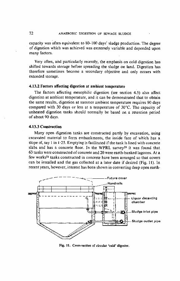
72 ANAEROBIC DIGESTION OF SEWAGE SLUDGE
capacity was often equivalent to 80-100 days' sludge production. The degreeof digestion which was achieved was extremely variable and depended uponmany factors.
Very often, and particularly recently, the emphasis on cold digestion hasshifted towards storage before spreading the sludge on land. Digestion hastherefore sometimes become a secondary objective and only occurs withextended storage.
4.13.2 Factors affecting digestion at ambient temperature
The factors affecting mesophilic digestion (see section 4.5) also affectdigestion at ambient temperature, and it can be demonstrated that to obtainthe same results, digestion at summer ambient temperature requires 90 dayscompared with 30 days or less at a temperature of 30 °C. The capacity ofunheated digestion tanks should normally be based on a retention periodof about 90 days.
4.13.3 Construction
Many open digestion tanks are constructed partly by excavation, usingexcavated material to form embankments, the inside face of which has aslope of, say 1 in 1 -25. Emptying is facilitated if the tank is lined with concreteslabs and has a concrete floor. In the WPRL survey29 it was found that63 tanks were constructed of concrete and 20 were earth-banked lagoons. At afew works51 tanks constructed in concrete have been arranged so that coverscan be installed and the gas collected at a later date if desired (Fig. 11). Inrecent years, however, interest has been shown in converting deep open earth-
Future cover
Handrails
Liquor decantingchamber
Sludge inlet pipe
— Sludge outlet pipe
Fig. 11. Cross-section of circular 'cold' digester.

ANAEROBIC DIGESTION OF SEWAGE SLUDGE 73
banked lagoons to heated digestion plants wherein the formation of a thickcrust limits losses of heat, and the installation of an oil-fired boiler can becarried out at minimal cost. Under good management control this systemworks satisfactorily; however, it must be recognized that the weed growth onthe thick crust formation hides the inherent dangers.
With rectangular tanks (Fig. 12) there is often an inlet at one end and anoutlet at the other end but with this arrangement there are likely to be deadpatches in the corners and short-circuiting is therefore experienced. Onearrangement75 which was found to be very efficient with an earth tankmeasuring 55 m x 42 m and 3 m deep was to have a submerged feed pipe ineach of three corners, discharging 0-9 m above floor level, with the outlet inthe fourth corner. An inlet discharging above sludge level can be used forbreaking up the scum.
Sludge inlet (preferably at least two)-Handrails
Sludge outlet
Fig. 12. Cross-section of rectangular 'cold' digester.
Over the last few years where the disposal of liquid sludge has beenpractised more commonly, outlet sumps have sometimes been provided forease of removal into tankers.
4.13.4 Operation
Mixing and circulation, which are usually very inefficient in rectangulartanks, are carried out by withdrawing sludge through the outlet and returningit to the inlet. Mixing is improved by having more than one outlet and inlet,and if possible should be carried out as a daily routine. Recirculation ofdigesting sludge should preferably proceed whilst raw sludge is being intro-duced.
When digestion is carried out in a single tank of large capacity, liquorwhich separates is difficult to locate and reach so that, although facilities

74 ANAEROBIC DIGESTION OF SEWAGE SLUDGE
for its withdrawal may be provided, much of the liquor is removed with thesludge. Periodically it may be desirable to remove any excessive build-up ofscum (or crust) using a drag line.
4.13.5 Performance
Reference to the literature76'77'78-79 shows that there is a shortage ofconsistent operational data available on the performace of 'cold' digesters.
4.14 Products of Anaerobic Digestion
The products of anaerobic digestion are (a) digested sludge, (b) liquor,and (c) gas.
4.14.1 Digested sludge
Digested sludge has a faint, relatively inoffensive tarry odour, and driesto an inert friable condition; a typical analysis is given in Table 1. In liquidform it is especially suitable for application to agricultural land, and a fulldiscussion of the subject is available elsewhere80.
4.14.2 Liquor
4.14.2.1 Composition. The results of analysis of liquors from four heateddigestion plants are given in Table 13. There was a wide variation in theconcentration of SS, with the solids being very finely divided and virtuallyunsettleable. Comparing the results of the filtered samples with those of the
TABLE 13. RESULTS OF ANALYSIS OF LIQUORS FROM FOUR LARGE SLUDGE DIGESTIONPLANTS
{Results in mg/l)
Suspended solids
PV
BOO
COD
Organic carbon
Ammonia (as N)
Total solids
Anionic detergent (as Manoxol OT)
Unfiltered
Range
295-1115
140-200
373-515
1500-1760
444-590
734-1000
1885-2265
22-33
Average
785
170
450
1650
525
820
2050
28
Filtered
Range
80-120
120-205
500-750
197-260
-
1070-1590
10-24
Average
95
150
610
225
—
1270
14

ANAEROBIC DIGESTION OF SEWAGE SLUDGE 75
unfiltered samples, it is evident that the SS are responsible for a considerableproportion of the BOD which is exerted by the liquors.
4.14.2.2 Treatment. The liquor is usually returned to the works' inlet, at acontrolled rate, to be treated in admixture with the incoming sewage. Separatetreatment of liquors has been shown to be difficult.
Because nitrogenous organic compounds are decomposed during digestionsome of the nitrogen passes into solution and therefore into the returnedliquor, thereby imposing an additional nitrogen loading on the treatmentplant.
4.14.3 Sludge gas
4.14.3.1 Composition. Sludge gas, which is saturated with water vapour,contains 65-70 per cent methane and 30-35 per cent carbon dioxide by volumedepending upon the organic matter which is being degraded (see Appendix 2).It also contains traces of unsaturated hydrocarbons with very small but widelyvarying concentrations of hydrogen sulphide. For example, at Birmingham81
this was considered to be due to varying amounts of iron in industrial wastewaters which were present in the sludge, the concentration of H2S beinginversely proportional to the iron content.
4.14.3.2 Calorific value. For gases which produce water on combustionthere are two calorific values, i.e. the net calorific value for combustion inwhich the water formed remains in the vapour phase, and the gross calorificvalue for combustion in which the water formed is condensed.
With sludge gas, heat is obtained almost exclusively from the combustionof methane. Calorific values are therefore calculated from the methanecontent82:
Net value = (334 x M) kJ/m3 (saturated with water)
Gross value = (370 X M) kJ/m3 (saturated with water)
(Both at 15-5°Cand 1 bar)
where M = percentage of methane.
The gross calorific value of sludge gas is normally 24 000-26 000 kJ/m3,the net calorific value being about 10 per cent less than this range.
4.14.3.3 Production. The composition and quantity of gas produced byanaerobic digestion depends upon the composition of the organic matterundergoing digestion. In theory the proportions of methane and carbon
76 ANAEROBIC DIGESTION OF SEWAGE SLUDGE
dioxide which are produced can be determined using Buswell's formula (seeAppendix 2).
Total gas production from the digestion of raw sewage sludge is typicallyabout 1-0 m3/kg organic and volatile matter destroyed. For a mixed primaryand secondary sludge, derived from a sewage which is predominantly ofdomestic origin, this is equivalent to about 0-5 m3/kg organic and volatilematter, or about 0-375 m3/kg total dry solids, added to the digester. In termsof contributing population, gas production is typically about 0-03 m3/hd d.Reports in the literature indicate that gas production may vary from 0-5-1 -2 m3/kg organic and volatile matter destroyed, or 0-3-0-7 m3/kg organic andvolatile matter added. Some of the large apparent variation can undoubtedlybe attributed to inaccuracies in determining the weight of organic and volatilematter added to or removed from the digester and to inaccuracies in measuringgas production. Leaks in and around digester roofs are also not uncommonand may account for apparently low gas production in relation to organic andvolatile matter destroyed.
4.14.3.4 Hazards. Hazards can arise from the methane, carbon dioxide, andhydrogen sulphide in sludge gas, the characteristics of which are given inTable 14.
(i) Methane. When methane leaks into the atmosphere a potentially flamma-ble mixture occurs when the concentration ranges from 5 per cent to 15per cent; below this concentration the flame is not self-propagating. It hasbeen suggested82 that any concentration of methane exceeding 1 -25 percent (25 per cent of the lower explosive limit) should be regarded asdangerous.
Methane is not a poisonous gas but in admixture with air may reducethe oxygen content of the mixture to such a level that asphyxiation occurs.
(ii) Carbon dioxide. The maximum safe concentration of carbon dioxide is 2-3 per cent in air; above this it is an asphyxiant.
(iii) Hydrogen sulphide. A concentration of 1-0 per cent (1500 mg/m3) ofhydrogen sulphide paralyses the sense of smell and causes instantunconsciousness. The physiological effects at different concentrations areshown in Table 14.
4.14.3.5 Precautions. The precautions which are necessary when workingin or around sludge digestion plants should be made known to all operators,

TABLE 14. CHARACTERISTICS AND PHYSIOLOGICAL EFFECTS OF GASES ENCOUNTERED IN SLUDGE DIGESTION PLANTS
Gas
CH4
CO,
H,S
Common properties
Colourless, odourless, flammableand forms explosive mixture withair
Colourless, odourless, non-flammable
Colourless, smells of rotten eggs.Flammable (may travel consider-able distance to a source of ignitionand flash back)
Specificgravity
or vapourdensity
(air =1)
0-55
1-53
1-19
Toxicology
Non-toxic but can have narcotic effectsin high concentrations in absence ofoxygen
Deprives tissues of oxygen by interferingwith oxygen-carrying capacity of oxy-haemoglobin
A simple asphyxiant Symptoms resultingonly when high concentrations arereached are headache, dizziness, drowsi-ness, tinnitus (ringing in ears). Removalfrom exposure results in rapid recovery
An irritant and asphyxiant, concentra-tions of 20-150 ppm cause eye irritation.Higher concentrations affect nervoussystem. A 30-minute exposure to500 ppm results in headache, dizziness,diarrhoea dysuria. A 30-minute exposureof 800-1000 ppm may be fatal. Itsasphyxiant action is due to paralysis ofrespiratory centre
Thresholdlimitvalue(TLV)(ppm)
—
5000
10
Maximum safe60 min exposure
(per cent byvolume in air)
Probably no limit,provided concen-tration of O, issufficient to sup-port life
4 0 - 6 0
002-003
Explosive range(per cent by
volume in air)
Lowerlimit
5 0
4-3
Upperlimit
1 5 0
4 6 0
>
m73OCOO
om
35
3ornv>r

78 ANAEROBIC DIGESTION OF SEWAGE SLUDGE
and appropriate "No Smoking" and "No Naked Lights" notices should bedisplayed prominently.
The recommended procedures8384 must be strictly adhered to for startingup or venting closed digesters and for preventing fires in the vicinity of diges-tion plants.
Formal training of all personnel with safety procedures for gas testingand use of resuscitation equipment is essential (see para. 4.8.3.4).
Operators should be provided with portable detectors for use beforeentering a potentially hazardous situation and detectors should be carried ontheir person which will give warning in sufficient time for an escape to be made.
4.14.3.6 Detection (see also section 4.6.6). Hazardous working conditionscan result from (a) a flammable atmosphere, (b) poisonous gases, or (c) oxygendeficiency. Each location will- have its own peculiarities and these must beknown to the operators and suitable equipment provided. Buildings which areassociated with digestion plants should be provided with gas detectors whichsound alarms if the atmosphere becomes potentially dangerous.
The technology of detection equipment is changing appreciably and modernequipment has advantages over that which was used only 5 years ago. Severaltypes should be examined before purchase and manufacturers are glad tosupply information about explosive and threshold limits. In addition, theliterature should be consulted81 •82'83-84-85>86.

5. Utilization of Sludge Gas
Sludge gas is normally used for heating the contents of a digester; however,surplus gas is quite commonly used for space heating on the treatment worksand for power production. It is also interesting to note that sludge gas hasbeen used for (a) incineration of screenings, (b) sludge drying, and (c) in anemergency for vehicle propulsion.
5.1 Power Production
At some large sewage-treatment works, including the major London plants,Birmingham (Minworth), and Manchester (Davyhulme), sludge gas is used forpower production, the waste heat from the engines being used for heating thesludge. Power which is derived from the engines may be used for generatingelectricity or for driving air compressors or pumps.
5.1.1 Economics
When comparing the cost of power generation from sludge gas with that ofpurchasing mains electricity many factors have to be taken into consideration.Although sludge gas may be free, costs of utilizing it for power productioninclude operating costs, loan charges and depreciation. Operating costs in-clude fuel oil for ignition, lubricating oil, stores and water, wages for shiftoperatives, and repairs and maintenance. Usually the power station housesother machinery such as compressors, pumps and sludge heating equipment.
When assessing the cost of mains electricity, to the price quoted may haveto be added a fixed standing charge, a maximum demand charge, and a chargebased on the price of coal. Also there may be transformer and transmissionlosses after the incoming meter. Other factors to be taken into considerationinclude the added reliability of having a works which is self-sufficient in power,especially with the possibility of either power failure or industrial action.Normally the capital and operating costs of the digestion plant are disre-garded.
There is usually a size of works at which the utilization of sludge gasfor power production becomes worthy of consideration. Expert opinion on
— 79 —

80 UTILIZATION OF SLUDGE GAS
this subject is often at variance and factors such as oil prices, labour, andinterest rates affect the economics.
5.1.2 Dual-fuel engines (Plates 7 and 8)
When sludge gas was first used for power production the conventional gasengine with a low compression ratio and spark ignition was used. About 1940,however, a gas engine was converted into a dual-fuel engine, with the gas beingfired in a high compression machine by a small charge of fuel oil mixed withthe gas, or fuel oil alone could be used if gas was unavailable. Dual-fuel enginesnormally produce a higher efficiency, exhaust temperatures are lower andmaintenance is reduced; they are easier to start and give smoother runningthan spark ignition gas engines. Table 11 gives particulars of some dual-fuelengine installations in the UK.
5.1.2.1 Description. A dual-fuel engine is basically a mechanical-injectiondiesel engine, with gas-mixing apparatus applied to its air intake system sothat, instead of inducing air only, a combustible mixture of air and gas isinduced and this mixture, after undergoing full compression in the workingcylinder, is fired by a small igniting charge of diesel fuel. This charge istimed and injected by the ordinary diesel fuel injection pump and sprayervalve into a gaseous mixture. The calorific value of the quantity of fuel oilinjection amounts to only 5-10 per cent of the total heat supplied at fullload87. If the gas supply fails an engine can be changed over from operating asa dual-fuel engine to diesel engine operation, and arrangements may be madefor this to be done automatically if required.
An engine should give its most economical output at three-quarters load,this being the average of its full load rating87, and when nearing the time for ageneral overhaul it should still be capable of coping with the load.
5.1.2.2 Operation. The operation of a dual-fuel engine will have beendescribed in the manufacturer's handbook and will not be discussed here.Suffice it to say that tripping out of an engine may be caused by: (a) the spindleof the needle valve in a fuel-injection nozzle 'shellacing', (b) mechanicalfailure of the gas-control gear, governors, etc., when changing from gas tooil, (c) load variations when testing an engine after overall, or (d) when theengine is direct coupled to an alternator, a voltage regulator needing servicing.
5.1.2.3 Maintenance. Dual-fuel engines need regular maintenance, basedusually on running hours. The frequency depends on the size and speed of theengine and it is important that servicing is carried out in accordance with themanufacturer's instructions.

UTILIZATION OF SLUDGE GAS 81
5.1.2.4 Performance. Efficiencies of dual-fuel engines range from 30-36 percent on full load or from 22-30 per cent under actual operating conditions.
Allowing for starting-up periods and test runs, gas consumption rangesfrom 0-45 to 0-55 m3/kWh, the consumption being higher with a varying load.
5.1.3 Other engines running on sludge gas
Supercharged dual-fuel engines are in operation at the Mogden works,Croydon's Beddington works, and Southampton's Millbrook works. AtLondon's Beckton works 10 gas turbines are in operation, 5 of which aredirectly coupled to blowers for the activated-sludge plant. The turbines haveadvantages in that they run on sludge gas without the use of fuel oil for igni-tion, they are lighter and therefore the foundations may be cheaper, and theyoccupy a smaller space than dual-fuel engines; however, they are less efficient.
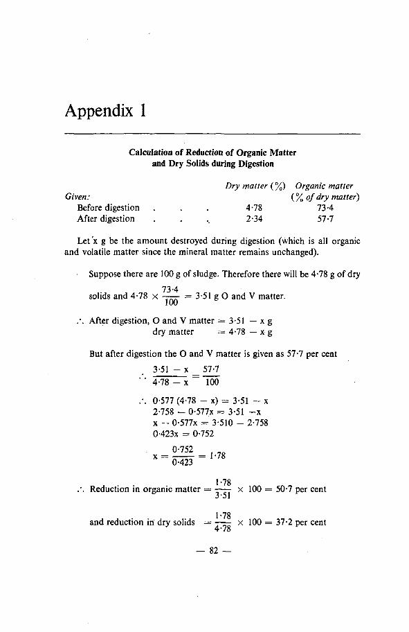
Appendix 1
Calculation of Reduction of Organic Matterand Dry Solids during Digestion
Dry matter (%) Organic matterGiven: {%°f dry matter)
Before digestion . . . 4-78 73-4After digestion . . .. 2-34 57-7
Let 'x g be the amount destroyed during digestion (which is all organicand volatile matter since the mineral matter remains unchanged).
Suppose there are 100 g of sludge. Therefore there will be 4-78 g of dry
73-4solids and 4-78 x —— = 3-51 g O and V matter.
.-. After digestion, O and V matter = 3-51 — x gdry matter = 4-78 — x g
But after digestion the O and V matter is given as 57-7 per cent
3-51 - x 57-7" ' 4-78 - x ~ 100
.-. 0-577 (4-78 - x) = 3-51 - x2-758 - 0-577x = 3-51 - xx - 0-577x = 3-510 - 2-7580-423x = 0-752
X - 0423 ~ l U
1-78.*. Reduction in organic matter = ——- x 100 = 50-7 per cent
1*78and reduction in dry solids = —— x 100 = 37-2 per cent
4*78
— 82 —

Appendix 2
Production of Digester Gas
The composition and quantity of digester gas which is produced by completedegradation depends upon the organic matter which is being broken downand, in theory, may be determined using Buswell's formula88:
If this formula is applied to the main classes of degradable organic matterthe values30 which are obtained are shown in Table 15.
TABLE 15. COMPOSITION AND VOLUME OF GAS FROM COMPLETE ANAEROBICDIGESTION OF DIFFERENT CLASSES OF ORGANIC MATTER
Material
Carbohydrate
Lipid
Protein
Composition*(per cent by weight)
CO,
73
52
73
CH,
27
48
27
Volume from 1 kg dry matter
Digester gas (m')
0-75
1-44
098
Methane (m1)
0-37
104
049
'Neglecting the very small amounts of other gases formed.
— 83 —

References
1. INSTITUTE OF WATER POLLUTION CONTROL. Glossary of Terms used in Water PollutionControl. Manuals of British Practice in Water Pollution Control, 1975.
2. BRUCE A. M., and BOON, A. G. Aspects of high-rate biological treatment of domesticand industrial waste waters. Wat.Pollut.Control, 70, 1971, (5), 487.
3. LEE, H. V., and DUCKWORTH, R. M. Aspects of power generation and sludge treatmentat Coventry. Wat.Pollut.Control, 73, 1974, (5), 469.
4. KENT, C. G. Extensions of the Manchester Corporation sewage works at Davyhulme.J.Proc.Inst.Sew.Purif, 1935, (1), 7.
5. MORRIS, A. T., COPELAND, C. E., and LEWIN, V. H. City of Oxford: Extension tosewage-treatment works. Wat.Pollut.Control, 69, 1970, (3), 249.
6. WATER RESEARCH CENTRE. Gravity Thickening of Biological Sludges. Tech. Report TR39,Feb. 1977.
7. CHRISTIAN, J. A. Reconstruction at Lundwood, Barnsley. J.Proc.Inst.Sew.Purif, 1962,(4), 342.
8. HAIGH, M. D. F. Sewage treatment at Barnsley 1961-71: A decade of set-backs andprogress. Wat.Pollut.Control, 72, 1973, (4), 373.
9. SURIYADASA, R. Redevelopment of Haven sewage-treatment works, Colchester.Wat.Pollut.Control, 72, 1973, (6), 693.
10. KERSHAW, M. A., and WOOD, R. Sludge treatment and disposal at Maple Lodge.J.Proc.Inst.Sew.Purif, 1966, (1), 75.
11. COTTON, P. City of Norwich sewage works. Wat.Pollut.Control, 67, 1968, (4), 454.
12. EDMONDSON, B. R. In discussion. Wat.Pollut.Control, 68, 1969, (2), 164.
13. BROWN, P., and THOMAS, A. Some experiences in the consolidation of surplus activatedsludge. Wat.Pollut.Control, 68, 1969, (2), 203.
14. LABOON, J. F. Experimental studies on the concentration of raw sludge. Sewage ind.Wastes, 24, 1952, 423.
15. RUDOLFS, W. Concentration of activated sludge by compaction and flotation. SewageWks.J.,lS, 1943,642.
16. AMES CROSTA BABCOCK. Komline-Sanderson Dissolved Air Flotation. Publication 102.
17. CLARK, E. I. Personal communication.
18. WATER RESEARCH CENTRE. Settling of Activated Sludge. Tech. Report TR 11, May 1975.
19. HIRST, G. Personal communication.
20. BUTLER, B. Personal communication.
— 84 —

21. GIIXETT, P. M. Personal communication.
22. Operation Manual: Sludge Handling and Conditioning. EPA 430/9-78-002, 1978.
23. WATER POLLUTION RESEARCH LABORATORY. The Aerobic Digestion of Sewage Sludge.WPRRep. No. 1271, 1972.
24. THAMES WATER AUTHORITY. Kidlington Aerobic Digestion Experiment. Final report ofsteering committee. July, 1976.
25. MCNICHOLAS, J. Personal communication.
26. WALKER, D. G., and MURDOCH, I. Thermophilic oxidative digestion of sludge usingoxygen. Preliminary report of the Ponthir pilot plant treatment. Welsh National WaterDevelopment Authority. January 1976.
27. WATSON, J. D. Sludge digestion. Proc.Ass.Mgrs Sewage Disp.Wks, 1923, 117.
28. O'SHAUGNESSY, F. R. Destructive anaerobic fermentation. Sewage Wks. J. 1931, 3, 86.
29. SWANWICK, J. D., SHURBEN, D. G., and JACKSON, S. A survey of the performance ofsewage sludge digesters in Great Britain. Wat.Pollut.Control, 68, 1969, (6), 639.
30. DEPARTMENT OF THE ENVIRONMENT. Anaerobic treatment processes and methaneproduction. Notes on Water Pollution. No. 64, March 1974.
31. STANBRIDGE, H. H. The consolidation and digestion of activated sludge. J.Proc.Inst.Sew.Purlf., 1966, (5), 492.
32. CHAPMAN, W. H. Some experiences on sludge digestion. J.Proc.Inst. Sew. Purif, 1965,(5), 485.
33. MOSEY, F. E. Assessment of the maximum concentration of heavy metals in crudesewage which will not inhibit the anaerobic digestion of sludge. Wat.Pollut.Control,75, 1976, (1), 10.
34. SWANWICK, J. D., and FOULKES, M. Inhibition of anaerobic digestion of sewage sludgeby chlorinated hydrocarbons. Wat.Pollut.Control, 70, 1971, (1), 58.
35. DEPARTMENT OF THE ENVIRONMENT. Inhibition in the anaerobic digestion process forsewage sludge. Notes on Water Pollution. No. 53, June 1971.
36. BARRETT, K. A. An investigation into the effects of chlorinated solvents on sludgedigestion. Wat.Pollut.Control, 71, 1972, (3), 389.
37. STICKLEY, D. P. The effect of chloroform in sewage on the production of gas from lab-oratory digesters. Wat.Pollut.Control, 69, 1970, (1), 55.
38. BRUCE, A. M., SWANWICK, J. D., and OWNSWORTH, R. A. Synthetic detergents andsludge digestion: Some recent observations. Wat.Pollut.Control, 65, 1966, (5), 427.
39. SWANWICK, J. D. and SHURBEN, D. G. Effective chemical treatment for inhibition ofanaerobic sewage digestion due to anionic detergents. Wat.Pollut.Control, 68,1969, (2),190.
40. NEOTRONICS LTD. Protection by Detection. 1975.
41. JONES, C. E. Personal communication.
42. SWANWICK, K. H. Personal communication.
— 85 —

43. JONES, C. E. Personal communication.
44. PEARCE, M. H. Personal communication.
45. JONES, C. E. Personal communication.
46. ROBERTS, S. D. Personal communication.
47. THOMPSON, L. H. Personal communication.
48. BROWN, W. F. The Maple Lodge sewage purification works of the Colne ValleySewerage Board. J.Proc.lnst.Sew.Purif., 1950, (3), 316.
49. FEARN, R. J. Personal communication.
50. RITCHIE, I. B. Personal communication.
51. HAIGH, M. D. F. Personal communication.
52. Middle Lee Regional Drainage Scheme. J.Proc.lnst.Sew.Purif., 1956, (4), 369.
53. ROCK, W. C. Personal communication.
54. CLARK, E. I. Personal communication.
55. The starting up of digesters: a symposium. J.Proc.lnst.Sew.Purif., 1964. (4), 303.
56. SAMBIDGE, N. E. W. Commissioning of a primary heated digester. Wat.Pollut.Control,71, 1972, (1), 105.
57. MOSEY, F. E., SWANWICK, J. D., and HUGHES, Deborah A. Factors affecting the availa-bility of heavy metals to inhibit anaerobic digestion. Wat.Pollut.Control, 70, 1971,(6), 668.
58. MOSEY, F. E. Anaerobic biological treatment. In Symposium on Treatment of Wastesfrom the Food and Drink Industry. Institute of Water Pollution Control, University ofNewcastle-upon-Tyne, 1974.
59. OLIVER, W. E. Sewage works of the Borough of Sutton and Cheam: Operationalexperiences. J.Proc.lnst.Sew.Purif, 1963, (5), 434.
60. MOSEY, F. E., and HUGHES, Deborah A. The toxicity of heavy metal ions to anaerobicdigestion. Wat.Pollut.Control, 74, 1975, (1), 18.
61. SWANWICK, J. D., and FOULKES, M. Inhibition of anaerobic digestion of sewage sludgeby chlorinated hydrocarbons. Wat.Pollut.Control, 70, 1971, (1), 58.
62. LUMB, C , BROWN, D., and BOTTOMLEY, M. K. V. A chloroform problem at GreatWarford and its solution. Wat.Pollut.Control, 76, 1977, (4), 459.
63. TOWNEND, C; B. Reflections on twenty-five years in Middlesex. J.Proc.lnst.Sew.Purif,1962, (1), 19.
64. JACKSON, H. The sludge digestion plant of the Gravesend sewage disposal works.J.Proc.lnst.Sew.Purif, 1934, (2), 76.
65. STANBRIDGE, H. H. Operation and performance of the Hogsmill Valley sewage treatmentworks of the Greater London Council, 1958-1966. Wat.Pollut.Control, 67,1968, (1), 21.
66. DEPARTMENT OF THE ENVIRONMENT/NATIONAL WATER COUNCIL. The Sampling andInitial Preparation of Sewage and Waterworks' Sludges, Soils, Sediments and PlantMaterials Prior to Analysis. H.M.S.O., London, 1977.
— 86 —

67. NATIONAL JOINT HEALTH AND SAFETY COMMITTEE FOR THE WATER SERVICE. WaterIndustry Health and Safety at Work. Advisory Broadsheet 3-10.
68. WATER RESEARCH CENTRE. Chromatographic Analysis of Digester Gas. TR85, July 1978.
69. MINISTRY OF TECHNOLOGY. Water Pollution Research 1966. H.M.S.O., London, p. 109.
70. KLEECK, L. W. Van. Operation of sludge drying and sludge gas utilization units.Sewage Wks.J., 17, 1945, 1240.
71. PETTIGREW, F. Personal communication.
72. CASSIDY, J. E. Personal communication.
73. GREENE, G. Operation of the extended sewage works at Derby. J.Proc.Inst.Sew.Purif,1963, (3), 245.
74. COTTON, P. Personal communication.
75. STANBRIDGE, J. Maidenhead sewage works. J.Proc.Inst.Sew.Purif, 1964, (2), 175.
76. WINSOR, C. E. Some problems of sludge digestion at small sewage purification works.J.Proc.InstSew.Purif, 1965, (1), 93.
77. HOYLE, W. H. Sewage disposal at Exeter. J.Proc.Inst.Sew.Purif, 1936, (1), 8.
78. WARD, A. R. Sludge disposal at Stockport. J.Proc.Inst.Sew.Purif, 1935, (1), 204.
79. THORNHILL, S. Chesterfield sewage works. J.Proc.Inst.Sew.Purif, 1949, (3), 344.
80. INSTITUTE OF WATER POLLUTION CONTROL. Unit Processes. Sewage Sludge III:Utilization and Disposal. Manuals of British Practice in Water Pollution Control, 1977.
81. JENKINS, S. H. In discussion. J.Proc.Inst.Sew.Purif, 1964, (1), 44.
82. BURGESS, S. G., and WOOD, L. B. The properties and detection of sludge gas. J.Proc.Inst.Sew.Purif, 1964, (1), 24.
83. INSTITUTION OF CIVIL ENGINEERS AND MINISTRY OF HOUSING AND LOCAL GOVERNMENT.Safety in Sewers and at Sewage Works. 1969.
84. NATIONAL JOINT HEALTH AND SAFETY COMMITTEE FOR THE WATER SERVICE. WaterIndustry Health and Safety at Work. Advisory Broadsheet 7-6.
85. WOOD, L. B., and FOSSEY, P. The r61e of the scientist in safety measures at sewage works.Wat.Pollut.Control, 66, 1967, (4), 386.
86. Gow, W. F., and NEILLY, W. M. Health and Safety at Work with special reference toSafety in Sewers. Chart.mun.Engr, 105, Feb, 1978, 39.
87. POWNALL, E. R. Application of diesel and dual-fuel engines for sewage works duties.J.Proc.Inst.Sew.Purif, 1953, (2), 111.
88. BUSWELL, A. M., and MUELLER, H. F. Indust.Engng.Chem., 44, 1952, 550.
87 —

INDEX
A d d i t i o n o f r a w s ludge . . 4 3A e r o b i c digestion . . . 33Anae rob i c digest ion . . . 35A n i o n i c detergents . . . 4 2 , 6 3A u t o m a t i c gas m o n i t o r s . . 53
Biochemist ry of d iges t ion p r o c e s s . 37'Burper -mixer ' . . . . 48
C a r b o h y d r a t e s , decompos i t i on of . 38C a r b o n dioxide . . 76Cen t ra l screw mixing p u m p . . 46Centr i fugat ion . . . . 28Centrifuge, disc-stack
(or nozzle bowl) . . . 28Centrifuge, solid bowl , scroll . 30Cha rac t e r of sewage s ludges . 15Charac ter i s t ics of gases . . 77Circula t ion a n d mixing . . 43Combus t i b l e gas de t ec to r . . 53Commiss ion ing of digester . . 58C o m p o s i t i o n of r aw s ludge . . 40Conso l ida t ion t a n k s . . . 2 4 , 25Covers , fixed . . . . 51Cove r s , floating . . . . 51
D e c o m p o s i t i o n of c a r b o h y d r a t e s . 38Decompos i t i on of fats . . 39D e c o m p o s i t i o n of p ro te ins . . 38Detec t ion 78Dete rgen t s , an ion ic . . . 42Digesters , p r imary . . . 44 , 54Digesters , s econdary . . . 54Digesters secondary , des ign cri teria 56Diges ters s econda ry , o p e r a t i o n of. 58Diges ters secondary , pe r fo rmance of 70Diges t ion , ae rob ic . . . 33Diges t ion , anae rob i c . . . 35Digest ion a t amb ien t t e m p e r a t u r e . 70Digest ion a t amb ien t t e m p e r a t u r e ,
cons t ruc t ion . . . . 72Digesters a t amb ien t t e m p e r a t u r e ,
ope ra t ion of . . 73Diges ters a t a m b i e n t t e m p e r a t u r e ,
pe r fo rmance of . . . 74Diges t ion , b iochemis t ry of . . 37Diges t ion , microb io logy of . . 36Dig i ta l logic . . . . 54Disc-stock centrifuge . . . 28Dual-fuel engines . . . 80Dual-fuel engines , m a i n t e n a n c e of 80Dual-fuel engines , o p e r a t i o n of . 80Dual-fuel engines , p e r f o r m a n c e of 81
Economics of power p r o d u c t i o n . 79Electrolyt ic flotation . . . 27E m p t y i n g 66
F a c t o r s affecting a n a e r o b i cdigest ion . . . . 4 0 , 7 2
F a t s , decompos i t i on of . . 39F l a m e t r aps . . . . 69F lo ta t ion , electrolytic . . . 27F l o t a t i o n , gas . . . . 26F o a m i n g . . . . . 65Frequency of feeding . . . 59
G a s de tec tors . . . . 52, 53Gas-fired mul t i - tube heater . . 51G a s flotation . . . . 26G a s ho lders . . . . 51G a s mon i to r s , a u t o m a t i c . . 53Grav i ty sepa ra t ion . . . 23Gr i t a ccumula t i on . . . 65G u i d e rollers a n d rails . . 69
Halogena ted h y d r o c a r b o n s . . 4 1 , 63H a z a r d s 76Hea t e x c h a n g e r s . . . . 69He a vy meta ls . . . . 4 1 , 62H y d r o g e n su lphide . . . 76
Inh ib i to ry subs tances . . . 40Inh ib i t ion of digest ion . . 61In te rna l gas-lift p u m p s . . 48
Level a l a r m . . . . 69Limpet type hea t exchanger . 47Liquor , compos i t ion of . 7 4Liquor , t r e a tmen t of . . . 75Liquor , w i thdrawa l of separa ted . 58Lubr ica t ion . . . . 68
M a i n t e n a n c e . . . . 68Meta l s , heavy . . . . 41M e t h a n e . . . . . 76M e t h a n o g e n i c digest ion . . 37Microbio logy of digest ion . . 36Mixing a n d c i rcula t ion . . 43M o n i t o r i n g . . . . 67, 68M o n i t o r i n g equ ipmen t . . 54
N o n - m e t h a n o g e n i c digest ion . 37Nozz l e bowl centr i fuge . . 28Nu t r i en t s 40
Organ i c m a t t e r in s ludge . . 83O T O X 53
p H con t ro l . . . . 60p H va lue 44, 67Physiological effects of gases . 77Pipelines . . . . . 69P ipework 54Power p r o d u c t i o n . . . 79Precau t ions . . . . 76Pr imary digesters . . . 44 , 70Pr imary digesters , commiss ion ing
of 58P r i m a r y digesters , design cri teria . 45
— 88 —

Primary digesters, operation . 58Primary digesters, organic loading 45Primary digesters, performance of. 69, 71Primary digesters, shape of . . 46Primary digesters, sludge mixing
and circulation . . . 46Primary digesters, types . . 44Production of sludge . . . 13Products of anaerobic digestion . 74Proteins, decomposition of . 38
Raw sludge, addition of . 4 3Raw sludge, composition of . 40Reduction of dry solids . . 69, 82Reduction of organic matter . 69, 82Remedial measures . . . 61Ringrose gas detector . . . 52Rotating fence thickener . . 23
Sampling procedures .Scum formationSecondary digesters .Secondary digesters, design criteriaSecondary digesters, operation of.Secondary digesters, performance ofSeparation of liquor .Sludge gas, calorific value ofSludge gas, composition ofSludge gas, production ofSludge production
co-settleddigested (defn)humus .mixed .mixing and circulation
676454565571667575831315
15, 17, 19. 16, 18
20. 43 , 59
75,
p H value . . . . 44preliminary t rea tment . . 39
Sludge pr imary . . . 15, 17, 20raw (defn) . . . . 15screening . . . . 21secondary . . . 16, 2 0 , 4 0surplus activated . . . 1 6 , 1 9temperature . . . . 43tertiary 16, 19thickening/consolidat ion . . 21types of 15quanti ty/calculat ion of . . 17, 19withdrawal . . . . 61
Secondary digesters . . . 54Solid bowl, scroll centrifuge . 30Solids retention period . . 44Spiralarm gas detector . . 53Stratification . . . . 64Suspended solids loading . . 18Synthetics detergents . . . 63
Tempera tu re control . . . 60Thickening, effect of . . . 23Thickening tanks . . 23 , 24, 25Toxicity, moni tor ing of . 6 8
Unit process employed . . 14Utilization of sludge gas . . 79
Vacuum a n d pressure relief assembly 69Volatile acids, moni tor ing of . 67
Withdrawal of l iquor . . . 66Withdrawal of sludge . . . 61
89 —

MANUALS OF BRITISH PRACTICE INWATER POLLUTION CONTROL
Previous Manuals:
Glossary of Terms used in Water Pollution ControlDefinitions of terms used in connexion with sewerage, sewage treatment, the
treatment of industrial waste waters, and in pollution prevention and control.Includes definitions of engineering, financial, legal and scientific terms used in thisconnexion, terms associated with computerization, design, electrical equipment,instrumentation, laboratory control, management, process control techniques,safety equipment, telemetry, and work study. Short descriptions of industrialprocesses producing waste water are included, together with definitions of termsused in industry and in connexion with industrial waste control. Containspronunciations of difficult terms (especially biological terms) and ends with a listof acronyms. Where processes are known by several different names, preferredterms are given which it is hoped will be used in future throughout the waterindustry. An authoritative reference book, recommended for use by everyoneengaged in the water industry and especially by students. Price £3'50 (£2-50 tomembers, including subscribers); library edition £6 (£4 to members).
Preliminary ProcessesContains sections on screening and disintegration, grit removal, and
proportionment and treatment of storm sewage. It includes 25 line diagrams andphotographs and is complete with an index. Price £1 -50 (£1 to members).
Primary sedimentationContains sections on sedimentation, horizontal-flow tanks, radial-flow tanks,
upward-flow tanks, operation and maintenance of primary sedimentation tanks,pattern of flow in primary sedimentation tanks, special-purpose sedimentationtanks, aids to sedimentation, products of primary sedimentation, and septictanks. Contains 41 line diagrams and photographs, together with an index.Price £2-50 (£1 -75 to members).
Tertiary Treatment and Advanced Waste Water TreatmentTertiary treatment processes described include removal of solids by pro-
longed settlement, irrigation over grassland, microstraining, slow sand filters,rapid downward-flow sand filters, upward-flow sand filters, and upward-flowclarifiers. Under advanced treatment, methods are described for removal ofnitrogen compounds, phosphate, residual organic matter, and inorganic salts.These include chemical coagulation, activated carbon treatment, ozone treatment,ultrafiltration and reverse osmosis, electrodialysis, distillation and freezing, andion exchange. Contains 27 line diagrams and photographs and is complete withindex. Price £2-25 (£1-50 to members).
Sewage Sludge III: Utilization and DisposalContains sections on soil fertility, constituents of sewage sludges, heavy
metals, nutrients and micro-nutrients, pathogenic organisms, application ofsludge, disposal of liquid sludge to land, disposal of semi-dried sludge to land,dumping of sludge at sea and incineration. It includes 10 line diagrams, 12 platesand is complete with an index. Price £3-50 (£3 to members) including postageand packing.
Copies obtainable from the Institute's offices, Ledson House, 53 LondonRoad, Maidstone, Kent ME16 8JH, cash with order.
PRINTED IN ENGLAND BY EDWARDS THE PRINTERS LTD., COVENTRY