Embed Size (px)
Citation preview

IN THE UNITED STATES PATENT AND TRADEMARK OFFICE
In re Patent of: James E. Jervis U.S. Patent No.: 6,306,141 Issue Date: October 23, 2001 Serial No.: 08/483,291 Filing Date: June 7, 1995 Title: MEDICAL DEVICES INCORPORATING SIM ALLOY
ELEMENTS
Submitted via Electronic Filing Mail Stop PATENT BOARD Patent Trial and Appeal Board Commissioner for Patents P.O. Box 1450 Alexandria, VA 22313-1450
PETITION FOR INTER PARTES REVIEW OF U.S. PATENT NUMBER 6,306,141 UNDER 35 U.S.C. §§ 311-319
Edwards Lifesciences Corporation (“Edwards” or “Petitioner”) hereby
requests Inter Partes Review (“IPR”) of Claims 1-22 in U.S. Patent Number
6,306,141 (“the ’141 Patent”) (Exhibit 1001). A detailed statement supporting the
petition follows.
The requisite fee accompanies this request. If any additional fee is necessary,
the Director is authorized to charge Deposit Account No. 50-5226. This document,
together with all exhibits referenced herein, has been served on the patent owner at
the addresses of record for the ’141 Patent as reflected in the accompanying
Certificate of Service.
Petition for Inter Partes Review of U.S. Patent No. 6,306,141 Filed January 17, 2014
i
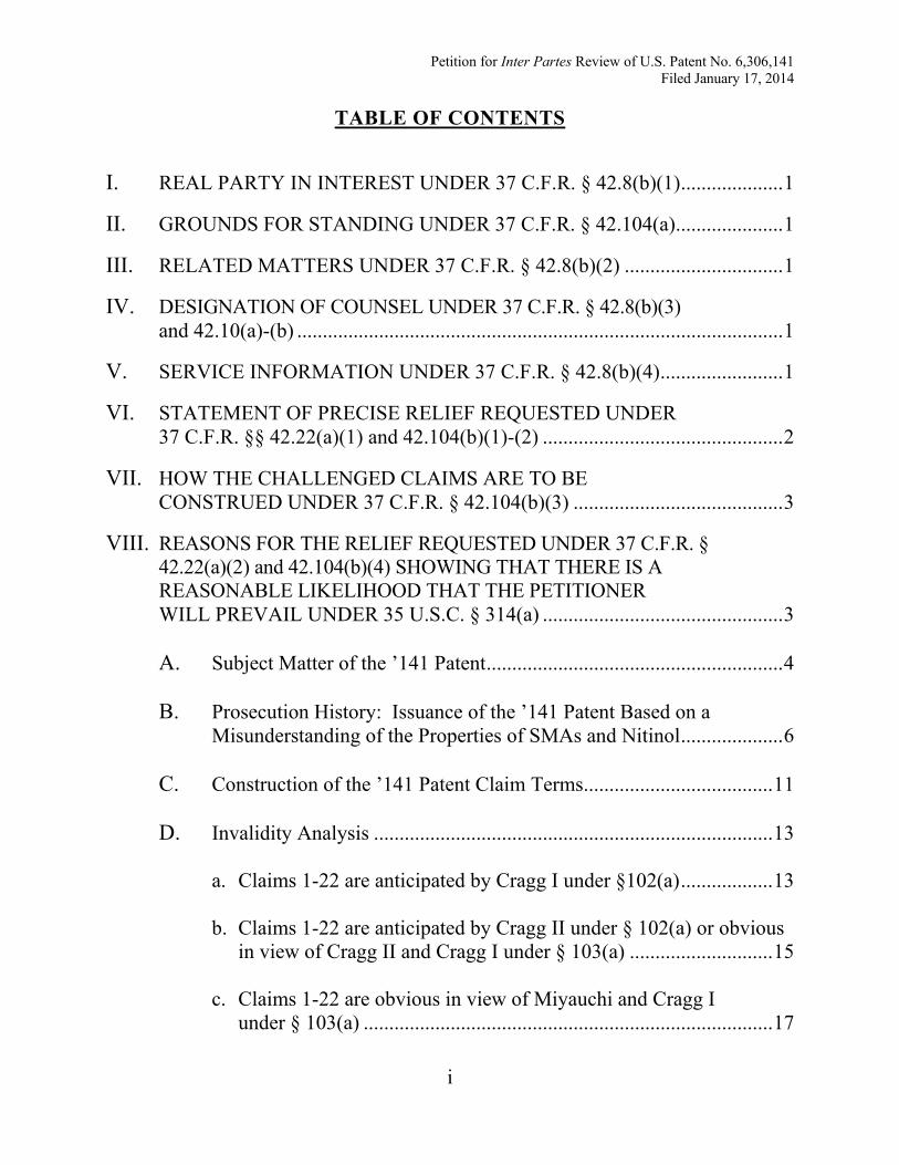
I. REAL PARTY IN INTEREST UNDER 37 C.F.R. § 42.8(b)(1) .................... 1
TABLE OF CONTENTS
II. GROUNDS FOR STANDING UNDER 37 C.F.R. § 42.104(a) ..................... 1
III. RELATED MATTERS UNDER 37 C.F.R. § 42.8(b)(2) ............................... 1
IV. DESIGNATION OF COUNSEL UNDER 37 C.F.R. § 42.8(b)(3) and 42.10(a)-(b) ............................................................................................... 1
V. SERVICE INFORMATION UNDER 37 C.F.R. § 42.8(b)(4) ........................ 1
VI. STATEMENT OF PRECISE RELIEF REQUESTED UNDER 37 C.F.R. §§ 42.22(a)(1) and 42.104(b)(1)-(2) ............................................... 2
VII. HOW THE CHALLENGED CLAIMS ARE TO BE CONSTRUED UNDER 37 C.F.R. § 42.104(b)(3) ......................................... 3
VIII. REASONS FOR THE RELIEF REQUESTED UNDER 37 C.F.R. § 42.22(a)(2) and 42.104(b)(4) SHOWING THAT THERE IS A REASONABLE LIKELIHOOD THAT THE PETITIONER WILL PREVAIL UNDER 35 U.S.C. § 314(a) ............................................... 3 A. Subject Matter of the ’141 Patent .......................................................... 4 B. Prosecution History: Issuance of the ’141 Patent Based on a Misunderstanding of the Properties of SMAs and Nitinol .................... 6 C. Construction of the ’141 Patent Claim Terms..................................... 11 D. Invalidity Analysis .............................................................................. 13
a. Claims 1-22 are anticipated by Cragg I under §102(a) .................. 13
b. Claims 1-22 are anticipated by Cragg II under § 102(a) or obvious in view of Cragg II and Cragg I under § 103(a) ............................ 15
c. Claims 1-22 are obvious in view of Miyauchi and Cragg I under § 103(a) ................................................................................ 17
Petition for Inter Partes Review of U.S. Patent No. 6,306,141 Filed January 17, 2014
ii
d. Claims 1-22 are obvious in view of the’212 Patent and Cragg I under § 103(a) ................................................................................ 19
e. Claim chart supporting invalidity grounds 1 through 4 ................. 21
f. Claims 1-22 are invalid for obviousness-type double patenting in view of the Jervis ’378 Patent ........................................................ 50
IX. CONCLUSION .................................................................................................. 60
Petition for Inter Partes Review of U.S. Patent No. 6,306,141 Filed January 17, 2014
iii
1001 U.S. Patent No. 6,306,141 to Jervis
EXHIBIT LIST
1002 Declaration of Ming H. Wu, Ph.D.
1003 Curriculum Vitae of Ming H. Wu, Ph.D.
1004 A. Cragg et al., Nonsurgical Placement of Arterial Endoprostheses: A New Technique Using Nitinol Wire, Radiology, 147: 261-263 (April 1983)
1005 A. Cragg et al., A New Percutaneous Vena Cava Filter, American Journal of Roentgenology, 141: pp. 601-604 (September 1983)
1006 Certified Translation of Japanese Patent Publication No. S58-46923 to Miyauchi et al. (filed Sept. 12, 1981; disclosed Mar. 18, 1983)
1007 U.S. Patent No. 3,620,212 to Fannon et al. (Granted Nov. 16, 1971)
1008 H. Ling et al., Phase Transitions and Shape Memory in NiTi, Metallurgical Transactions A, 11A: 77-79 (1980)
1009 U.S. Patent No. 4,503,569 to Dotter (Filed Mar. 3, 1983; Granted Mar. 12, 1985)
1010 L. Delaey et al., Thermoelasticity, Pseudoelasticity and the Memory Effects Associated with Martensitic Transformations. Part 1: Structural and Microstructural Changes Associated with the Transformations, Journal of Materials Science, 9: 1521-1535 (1974)
1011 R.V. Krishnan et al., Thermoplasticity, Pseudoelastiticy and the Memory Effects Associated with Martensitic Transformations. Part 2: The Macroscopic Mechanical Behavior, Journal of Materials Science, 9: 1536-1544 (1974)
1012 K. Otsuka et al., Pseudoelastiticy, Metals Forum, 4(3): 142-152 (1981)
Petition for Inter Partes Review of U.S. Patent No. 6,306,141 Filed January 17, 2014
iv
1013 J.R. Patel et al., Criterion for the Action of Applied Stress in the Martensitic Transformation, Acta Metallurgica, 1: 531-538 (1953)
1014 L.M. Schetky, Shape Memory Alloys, Scientific American, 241(5): 74-82 (1979)
1015 K. Otsuka et al., Stress and Strain Induced Martensitic Transformations, Proceedings of the Int’l Conference on Martensitic Transformations: ICOMAT 1979, 607-618 (Jun 1979)
1016 February 26, 2001 BPAI Decision (Excerpt from the ’141 Patent Prosecution History)
1017 March 18, 1998 Applicant Remarks to Office Action (Excerpt from
the ’141 Patent Prosecution History) 1018 April 2, 1997 Applicant Remarks to Office Action (Excerpt from
the ’141 Patent Prosecution History) 1019 March 18, 1998 Declaration of Dr. Lee Middleman (Excerpt from
the ’141 Patent Prosecution History) 1020 U.S. Patent No. 5,597,378 to Jervis 1021 T.L. Lopes et al., Fatigue Performance of Nitinol Tubing with Af of
25ºC, Proceedings of the International Conference on Shape Memory and Superelastic Technologies, 311-320 (2003)
1022 M. Wu et al., What is the Big Deal About the Af Temperature?,
Proceedings of the International Conference on Shape Memory and Superelastic Technologies, 143-154 (May 2006)
1023 D.B. Chernov et al., The Multiplicity of Structural Transitions in
Alloys Based on TiNi, Soviet Physics Doklady, 24(8): 664-666 (Aug. 1979)
1024 Original Japanese Patent Publication No. S58-46923 to Miyauchi et al. (filed Sep. 12, 1981; disclosed Mar. 18, 1983)
1025 Complete Prosecution History of the ’141 Patent
Petition for Inter Partes Review of U.S. Patent No. 6,306,141 Filed January 17, 2014
v
1026 Certified Transcript of Deposition of Dr. Lee Middleman, taken December 10-11, 2008
1027 G.B. Kauffman et al., The Story of Nitinol: The Serendipitous Discovery of the Memory Metal and Its Applications, The Chemical Educator, 2(2): 1-21 (1996)
1028 T.W. Duerig et al., Ti-Ni Shape Memory Alloys, Materials Properties Handbook: Titanium Alloys, 1035-48 (1994)
1029 M. Simon et al., A Vena Cava Filter Using Thermal Shape Memory Alloy, Radiology, 125: 89-94 (1977)
1030 U.S. Patent No. 4,425,908 to Simon (Filed Oct. 22, 1981; Granted Jan. 17, 1984)
1031 U.S. Patent No. 4,512,338 to Balko et al. (Filed Jan. 25, 1983; Granted Apr. 23, 1985)
1032 F.E. Wang et al., The Irreversible Critical Range in the NiTi Transition, Journal of Applied Physics, 39(5): 2166-2175 (April 1968)
1033 Complete Prosecution History of U.S. Patent No. 5,597,378
Petition for Inter Partes Review of U.S. Patent No. 6,306,141 Filed January 17, 2014
1
I.
The Petitioner is EDWARDS LIFESCIENCES CORPORATION.
REAL PARTY IN INTEREST UNDER 37 C.F.R. 42.8(b)(1)
II.
Petitioner certifies that the ‘141 Patent is available for IPR and that
Petitioner is not barred or estopped from requesting an IPR challenging the patent
claims on the grounds identified herein.
GROUNDS FOR STANDING UNDER 37 C.F.R. 42.104(a)
III.
Petitioner is not aware of any current judicial or administrative matters that
would affect, or be affected by, a decision in this proceeding.
RELATED MATTERS UNDER 37 C.F.R. 42.8(b)(2)
IV.
Lead counsel for the Petitioner is David S. Moreland of Meunier Carlin &
Curfman, LLC, USPTO Reg. No. 60,134. Backup counsel for the Petitioner is
Gregory J. Carlin of Meunier Carlin & Curfman, LLC, USPTO Reg. No. 45,607.
Pursuant to 37 C.F.R § 42.10(b), a Power of Attorney accompanies this petition.
DESIGNATION OF COUNSEL UNDER 37 C.F.R. 42.8(b)(3) and 42.10(a)-(b)
V.
Petitioner’s lead counsel may be reached by phone at (678) 869-7749, by
email at
SERVICE INFORMATION UNDER 37 C.F.R. 42.8(b)(4)
David S. Moreland
, and by facsimile at (404) 645-7707.
Petitioner may be served as follows:
MEUNIER CARLIN & CURFMAN, LLC 817 W. Peachtree Street NW, Suite 500 Atlanta, GA 30308
Petition for Inter Partes Review of U.S. Patent No. 6,306,141 Filed January 17, 2014
2
VI.
For the reasons presented herein, Petitioner seeks the following relief:
STATEMENT OF PRECISE RELIEF REQUESTED UNDER 37 C.F.R. §§ 42.22(a)(1) and 42.104(b)(1)-(2)
(Ground #1) Invalidation of Claims 1-22 of the ‘141 Patent (“the ’141
Patent Claims”) under 35 U.S.C. § 102(a) as being anticipated by Cragg et al.,
Nonsurgical Placement of Arterial Endoprostheses: A New Technique Using
Nitinol Wire, 147 Radiology No. 1, 261-263 (April 1983) (“Cragg I,” Exhibit
1004);
(Ground #2) Invalidation of Claims 1-22 of the ’141 Patent under 35 U.S.C.
§ 102(a) as being anticipated by Cragg et al., A New Percutaneous Vena Cava
Filter, 141:601-604 (September 1983) (“Cragg II,” Exhibit 1005) or, alternatively,
under 35 U.S.C. § 103(a) as being obvious in view of Cragg I and Cragg II.
(Ground #3) Invalidation of Claims 1-22 of the ‘141 Patent under 35 U.S.C.
§ 103(a) as being obvious in view of Japanese Patent Publication No. S58-46923 to
Miyauchi et al. (“Miyauchi,” Japanese publication at Exhibit 1024, and certified
English translation at Exhibit 1006) in view of Cragg I.
(Ground #4) Invalidation of Claims 1-22 of the ‘141 Patent under 35 U.S.C.
§ 103(a) as being obvious in view of U.S. Patent No. 3,620,212 to Fannon (“the
’212 Patent,” Exhibit 1007) in view of Cragg I.
(Ground #5) Invalidation of Claims 1-22 of the ’141 Patent under the
doctrine of obviousness-type double patenting over the claims of U.S. Patent No.
Petition for Inter Partes Review of U.S. Patent No. 6,306,141 Filed January 17, 2014
3
5,597,378 to Jervis (“the ’378 Patent,” Exhibit 1007), filed October 2, 1992;
issued on January 28, 1997; and expired on May 4, 2004.
VII.
The ’141 Patent Claims should be accorded their “broadest reasonable
construction” in light of the specification of the ‘141 Patent. 37 C.F.R. § 42.100(b).
HOW THE CHALLENGED CLAIMS ARE TO BE CONSTRUED UNDER 37 C.F.R. § 42.104(b)(3)
VIII.
The ’141 Patent Claims are invalid in light of several prior art references and
in view of an expired patent to the same inventor covering the same subject matter.
As will be explored, the ‘141 Patent claims issued because the PTAB was provided
incorrect information regarding the material properties of shape-memory alloys, in
particular Nitinol, through a declaration of an “expert” in stress induced martensite
submitted by the Applicant Medtronic during the prosecution of the ’141 Patent.
This declarant has since admitted that he is not and never was an expert in the
relevant subject matter. But for this declaration, the ’141 Patent would not have
issued. When viewed under a clear lens, the ’141 Patent is even more undeniably
invalid in view of the prior art.
REASONS FOR THE RELIEF REQUESTED UNDER 37 C.F.R. § 42.22(a)(2) and 42.104(b)(4) SHOWING THAT THERE IS A REASONABLE LIKELIHOOD THAT THE PETITIONER WILL PREVAIL UNDER 35 U.S.C. § 314(a)
Further, the ‘141 Patent claims priority to U.S. Appl. No. 06/541,852 (“852
Application”), filed October 13, 1983. As a result of terminal disclaimers based on
Petition for Inter Partes Review of U.S. Patent No. 6,306,141 Filed January 17, 2014
4
obviousness-type double patenting rejections, the other patents issuing from the
’852 Application all expired on May 4, 2004. The ‘141 Patent, however, was
improperly granted without requiring a surrender of the patent term past this date.
As such, the ’141 Patent now exists as an improper extension of the patent
monopoly and is invalid on those grounds too.
A. Subject Matter of the ‘141 Patent
The ’141 Patent Claims are generally directed to a medical device that
includes (i) a shape memory alloy (SMA) element capable of displaying stress-
induced martensite (SIM) at body temperature, and (ii) a placement device for
delivery of the SMA element into a mammal (see ‘141 Patent (Exhibit 1001) at
2:59 to 3:4 and 10:59 to 14:23). SMAs display a “martensitic” phase and an
“austenitic” phase. Just as water can transform between various phases (e.g., vapor,
liquid, ice), SMAs can reversibly transform between their austenitic and
martensitic phases/states.
The transformation between these phases can occur as a result of a change in
temperature or stress. For example, just like when H2O is in its liquid phase (water)
and is sufficiently cooled, it transforms to its solid state (ice). When a SMA is in
its austenite phase and it is sufficiently cooled, it transforms to its martensite
phase. This transformation as a result of temperature is referred to as “thermally
induced martensite” or “TIM.” Likewise, the application of sufficient stress to a
Petition for Inter Partes Review of U.S. Patent No. 6,306,141 Filed January 17, 2014
5
SMA when in its austenite phase will transform the SMA to its martensite phase.
This transformation as a result of stress is referred to as “stress induced
martensite” or “SIM” (see ‘141 Patent at 1:52-53). Importantly, every SMA that
exhibits TIM also exhibits SIM. That is, these martensitic transformations are
equivalent and inherent material properties of the SMA. This fact was never
disclosed by the Applicant. To the contrary, the Board of Patent Appeals and
Interferences (“the Board”) was misled into concluding that not all SMAs that
exhibit TIM exhibit SIM (i.e., that additional processing is required to exhibit
SIM) (see generally Exhibit 1019). Moreover, the Board allowed the ’141 Patent
Claims based on this incorrect belief (see generally Exhibit 1016).
SMAs have a “shape memory” property that enables them to memorize their
austenitic shape. That memory can be exhibited in several ways: thermal shape
memory, pseudoelasticity, and mechanical shape memory. Thermal shape memory
refers to when one sufficiently cools an SMA containing austenite to form
thermally induced martensite, deforms the martensite, and then heats the alloy so
that it reverts from thermally induced martensite back to its undeformed austenitic
state (’141 Patent at 2:23-28). Pseudoelasticity refers to the conversion of austenite
to martensite, but where the martensite is formed by the application of stress
(rather than by significant cooling), and the release of stress allows the austenite
phase to be restored (’141 Patent at 1:52—2:1). Mechanical shape memory is
Petition for Inter Partes Review of U.S. Patent No. 6,306,141 Filed January 17, 2014
6
similar to pseudoelasticity, in that martensite is formed by the application of stress,
but the stress-induced martensite is stable until the austenite transformation start
temperature (As) of the SMA is reached (see id.).
Each of the shape memory properties described above may exist as natural
material properties of Nitinol. Nitinol is a well-known SMA formed of nickel and
titanium, and was frequently used in self-expanding medical devices in the late
1970’s and early 1980’s. Nitinol is disclosed in all of the prior art references
discussed herein (and is discussed in detail in the ’141 Patent (see ‘141 Patent at
9:14 to 10:7)).
An understanding of the material properties of Nitinol and its transformation
temperatures is important in assessing the validity of the ’141 Patent Claims. To
assist the Board in that regard, Petitioners have submitted the declaration of Dr.
Ming H. Wu (“Expert Report” or “ER,” Exhibit 1002). Dr. Wu has extensive
knowledge of SMAs, including over 30 years of experience in the use of SMAs in
medical devices. Dr. Wu specifically addresses the material properties of Nitinol,
the prior art disclosing the use of Nitinol in medical devices, and the relevance of
these disclosures to the ’141 Patent Claims.
B. Prosecution History: Issuance of the ’141 Patent Based on a Misunderstanding of the Properties of SMAs and Nitinol
The ‘141 Patent characterizes its alleged improvement as a medical device
using “the substitution of an alloy element which displays stress-induced martensite
Petition for Inter Partes Review of U.S. Patent No. 6,306,141 Filed January 17, 2014
7
at body temperature” in place of using thermally induced martensite to achieve
the same result (see ’141 Patent at 3:1-4 (emphasis added)). Thus, the basic
premise of the ’141 Patent (in its own terms) is to substitute one well-known SMA
material property, stress induced martensite (SIM), for another well-known and
equivalent material property, thermally induced martensite (TIM) (see ’141 Patent
at 1:52-59 (admitting that SMAs that exhibit SIM were well known in the art)).
Indeed, the Applicant recognized the alleged invention’s lack of novelty, conceding
it was only a “basic improvement” that “uses stress-induced martensite material in
place of conventional [thermally induced] shape memory alloy material” (Remarks
to Office Action (Exhibit 1017) at 3).
Under KSR Int’l Co. v. Teleflex, Inc., 550 U.S. 398 (2007) and its progeny,
substitution of a known material element to obtain a predictable result fails the
threshold for patentability.1
1 The ’141 Patent was granted on October 23, 2001, thus before the Supreme
Court’s April 30, 2007 KSR decision.
See, e.g., Unigene Labs., Inc. v. Apotex, Inc., 655 F.3d
1352, 1361 (Fed. Cir. 2011) (“[D]esign need and market pressure may dictate a
commonsensical path using a finite number of identified predictable solutions to
one of ordinary skill….”); see also In re Chevalier, 500 Fed. Appx. 932, 935 (Fed.
Cir. 2013) (ruling that “recognized equivalents performing the same function”
rendered claims obvious based on KSR’s recognition that “when a patent claims a
Petition for Inter Partes Review of U.S. Patent No. 6,306,141 Filed January 17, 2014
8
structure already known in the prior art that is altered by the mere substitution of
one element for another known in the field, the combination must do more than
yield a predictable result.”) (citing KSR, 550 U.S. at 416).
Moreover, as explained by Dr. Wu, no substitution was required. The ‘141
Patent incorrectly suggests that the known shape memory elements in medical
devices only exhibited thermally induced martensite (TIM) (’141 Patent at 1:26—
2:54, 9:14—10:7). However, the prior art expressly recognized and relied upon the
SMA material property of stress induced martensite (SIM) and its conversion back
to austenite (see, e.g., ER §VII). In other words, the prior art disclosed the use of
SIM (rather than TIM) to obtain the desired shape memory property in self-
expanding medical devices. The ’141 Patent Claims are invalid in view of such
prior art.
In prosecuting the ’141 Patent, the Applicant Medtronic argued that all
Nitinol SMAs that exhibit thermally induced martensite (TIM) do not exhibit stress
induced martensite (SIM). More particularly, the Examiner issued a Final Office
Action rejecting the ’141 Patent Claims as obvious (Final OA, Sept. 15, 1997
(Exhibit 1025) at 2-3). Medtronic appealed and submitted a declaration by Dr. Lee
Middleman, whom Medtronic represented as “an expert in the field of stress-
induced martensite (SIM) alloy elements” (141 History, Appeal Brief, Jun. 18,
1998 (Exhibit 1025) at 18). Dr. Middleman stated:
Petition for Inter Partes Review of U.S. Patent No. 6,306,141 Filed January 17, 2014
9
Although nitinol can exhibit properties of an SIM material, it
can do so only if it undergoes a treatment process to make it
exhibit the properties of an SIM material.
This process requires
an extensive, time consuming, and expensive procedure. Where
is the suggestion in Balko or any of the other references to use
nitinol exhibiting SIM behavior rather than less expensive
conventional Nitinol? There is no such suggestion....
(Middleman Decl. (Exhibit 1019) at 4 (emphasis added)).
The Board in turn reversed the Examiner’s decisions, relying inter alia on
Dr. Middleman’s declaration:
As shown by Kirk-Othmer and the Middleman declaration,
nitinol does not exhibit SIM properties unless it receives
additional treatment,
of which there is no suggestion in Balko.
We therefore conclude that the examiner has not made out a
prima facie case that the SMAs disclosed by Balko would
inherently display SIM properties.
(Id. at Decision on Appeal, Feb. 26, 2001, p. 6 (emphasis added).)
While the Board understandably accepted Dr. Middleman’s representations
in the ex parte process (because Medtronic represented that Middleman was an
expert in SIM with knowledge of Nitinol processing), the reality is that Dr.
Middleman was not then and is not now an expert in SIM or Nitinol. Indeed,
during the course of subsequent litigation regarding the ’141 Patent, Dr.
Middleman admitted that he is not an expert in either (see Middleman Deposition
Petition for Inter Partes Review of U.S. Patent No. 6,306,141 Filed January 17, 2014
10
(Exhibit 1028) at pp. 29, 34, 100, 146-148, 229 (testifying that he “was definitely
not an expert in Nitinol” and was “absolutely not” an expert in “stress-induced
martensite”)).
In contrast, Dr. Wu (an actual expert in SMAs), explains that all SMAs
including Nitinol that can exhibit thermally induced martensite (TIM) can also
exhibit stress induced martensite (SIM) (ER §§IV-VII). This follows fundamental
thermodynamic principles, and no special treatment is required for a Nitinol alloy
that exhibits TIM to also exhibit SIM (ER §§IV-VII). The requirement for “an
additional treatment” process that is “extensive, time-consuming and expensive,”
as set forth in the Middleman declaration is quite simply incorrect (see ER VI).
All of the prior art references relied on herein use a Nitinol alloy element in
a self-expanding medical device. In considering them, it is important to keep in
mind the following fundamental material properties of SMAs:
• Shape memory alloys that are capable of exhibiting TIM are also capable
of exhibiting SIM (see, e.g., ER §IV).
• All Nitinol SMAs exhibit SIM between their Mf and Md temperatures
(see, e.g., ER §IV). (The Mf temperature is the temperature at which the
SMA is fully martensitic based solely on the temperature; the Md
temperature is the temperature above which martensite will no longer
form under stress (see id.)).
Petition for Inter Partes Review of U.S. Patent No. 6,306,141 Filed January 17, 2014
11
• All Nitinol SMAs exhibit pseudoelasticity between As and Md
temperatures (see, e.g., ER §IV). (The As temperature is the temperature
at which martensite begins to revert back to austenite—whether formed
through stress or temperature (see id.)).
• All Nitinol SMAs are thus indisputably pseudoelastic shape memory
alloys (see, e.g., ER §§IV-VIII).
Dr. Wu, an acknowledged expert in SMA’s, states the scientific bases for
these fundamental properties in his declaration attached as Exhibit 1002.
C. Construction of the ’141 Patent Claim Terms The claims are construed as a person of ordinary skill in the art would
understand them and are to be given their broadest reasonable construction. For
example, Claim 1 recites that “the alloy is selected so that the transformation can
occur without any change in temperature of the placement device or the memory
alloy element.” The “transformation” in the claim is the transformation of the
medical device from stress-induced martensite (SIM) to austenite. The time of
transformation (as dictated by the claims) is when the medical device is released
from the placement device inside the mammal. Thus, to one of ordinary skill in the
art, the SMA selected must merely be capable of transforming (note use of phrase
“can occur”) from SIM to austenite when placed in the body “without any change
Petition for Inter Partes Review of U.S. Patent No. 6,306,141 Filed January 17, 2014
12
in temperature of the … memory alloy element” (ER §VIII).2
Other claim terms and limitations should similarly be given their broadest
reasonable construction. For example, consistent with this approach, the patent
teaches a broad definition of “catheters” to include “cannulas” (see ’141 Patent at
5:60-62 (“both [terms] being included hereinafter in the word “catheter”)).
This limitation is met
when an alloy is selected that has an As temperature below body temperature (id.).
With such an As temperature, the memory alloy device self-expands when released
in the body without requiring a change in temperature, which is exactly what is
disclosed in the prior art (ER §§VII-VIII).
2 Non-limiting language as it relates to the “change in temperature” limitation is
similarly used throughout the independent claims: Claim 11 (“without any change
in temperature … being required”); Claim 15 (“selected so that the transformation
can occur without any change in temperature”); Claim 16 (“can occur without a
change in temperature”); Claim 18 (“selected so the transformation can occur
without any change in temperature”). Such limitations similarly require only that
the selected SMA be capable of transforming from SIM to austenite when released
in the body without a change in temperature, not that the SMA actually transform
without a change in temperature (even though the prior art does disclose such a
transformation without a change in temperature) (ER §§VII-VIII).
Petition for Inter Partes Review of U.S. Patent No. 6,306,141 Filed January 17, 2014
13
D. Invalidity Analysis
a. Claims 1-22 are anticipated by Cragg I under § 102(a)
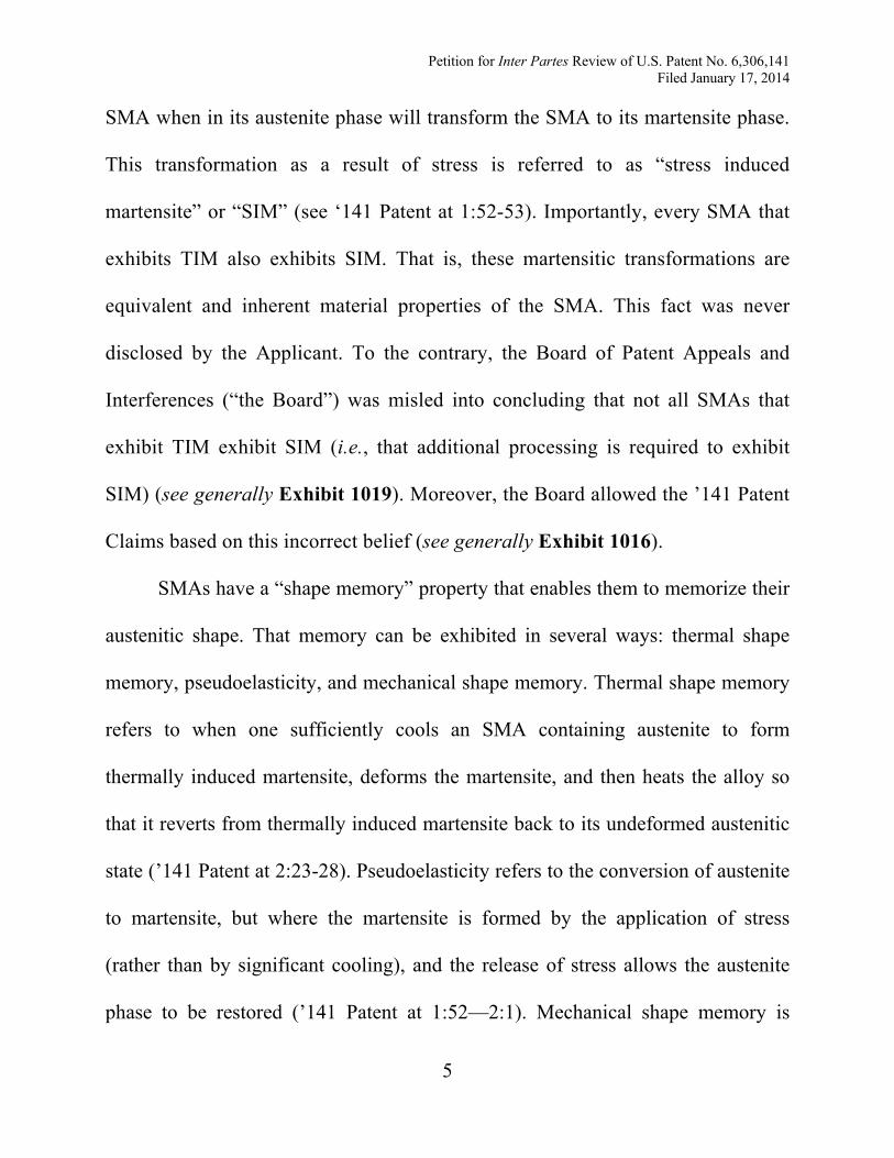
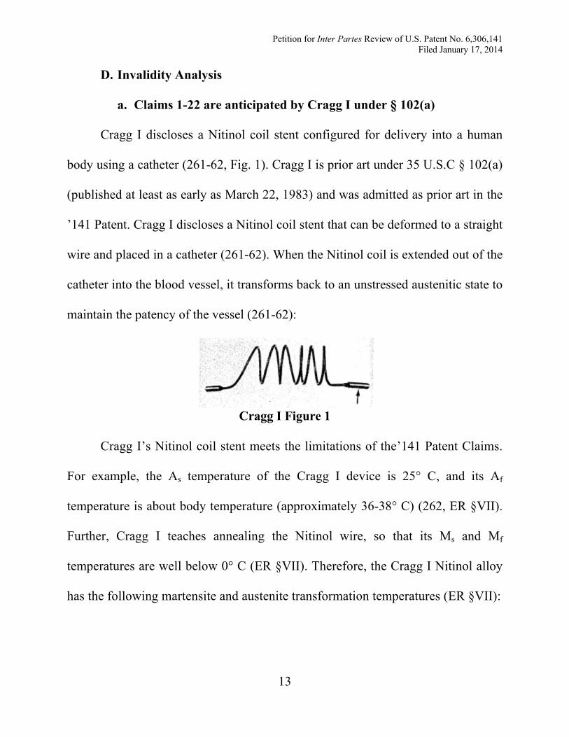
Cragg I discloses a Nitinol coil stent configured for delivery into a human
body using a catheter (261-62, Fig. 1). Cragg I is prior art under 35 U.S.C § 102(a)
(published at least as early as March 22, 1983) and was admitted as prior art in the
’141 Patent. Cragg I discloses a Nitinol coil stent that can be deformed to a straight
wire and placed in a catheter (261-62). When the Nitinol coil is extended out of the
catheter into the blood vessel, it transforms back to an unstressed austenitic state to
maintain the patency of the vessel (261-62):
Cragg I Figure 1
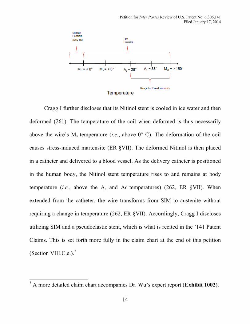
Cragg I’s Nitinol coil stent meets the limitations of the’141 Patent Claims.
For example, the As temperature of the Cragg I device is 25° C, and its Af
temperature is about body temperature (approximately 36-38° C) (262, ER §VII).
Further, Cragg I teaches annealing the Nitinol wire, so that its Ms and Mf
temperatures are well below 0° C (ER §VII). Therefore, the Cragg I Nitinol alloy
has the following martensite and austenite transformation temperatures (ER §VII):
Petition for Inter Partes Review of U.S. Patent No. 6,306,141 Filed January 17, 2014
14
Cragg I further discloses that its Nitinol stent is cooled in ice water and then
deformed (261). The temperature of the coil when deformed is thus necessarily
above the wire’s Ms temperature (i.e., above 0° C). The deformation of the coil
causes stress-induced martensite (ER §VII). The deformed Nitinol is then placed
in a catheter and delivered to a blood vessel. As the delivery catheter is positioned
in the human body, the Nitinol stent temperature rises to and remains at body
temperature (i.e., above the As and Af temperatures) (262, ER §VII). When
extended from the catheter, the wire transforms from SIM to austenite without
requiring a change in temperature (262, ER §VII). Accordingly, Cragg I discloses
utilizing SIM and a pseudoelastic stent, which is what is recited in the ’141 Patent
Claims. This is set forth more fully in the claim chart at the end of this petition
(Section VIII.C.e.).3
3 A more detailed claim chart accompanies Dr. Wu’s expert report (Exhibit 1002).
Petition for Inter Partes Review of U.S. Patent No. 6,306,141 Filed January 17, 2014
15
b. Claims 1-22 are anticipated by Cragg II under § 102(a) or rendered obvious in view of Cragg II and Cragg I under § 103(a)
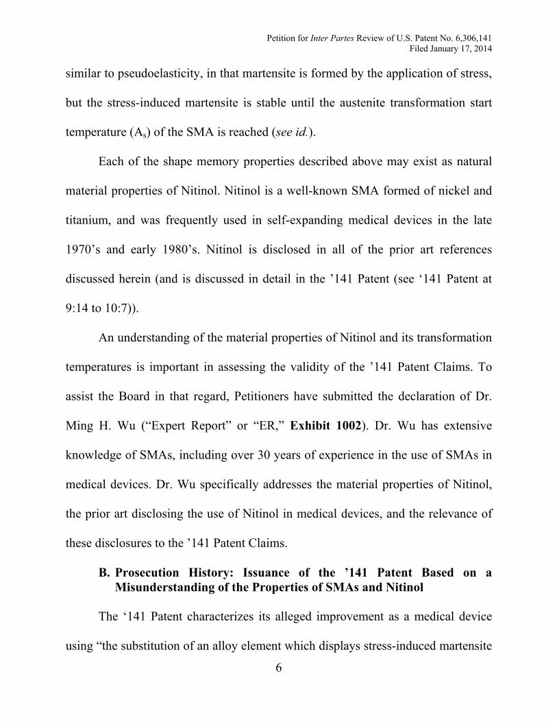
Cragg II, which was not before the Patent Office during the examination of
the ’141 Patent, is prior art under 35 U.S.C § 102(a) (published at least as early as
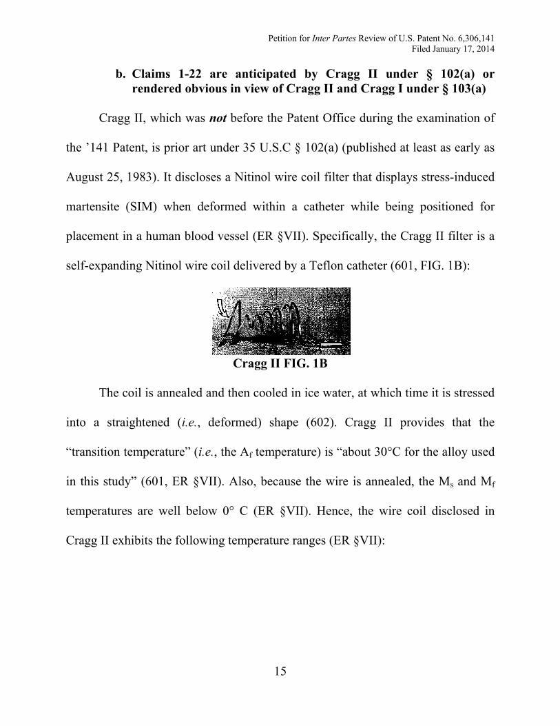
August 25, 1983). It discloses a Nitinol wire coil filter that displays stress-induced
martensite (SIM) when deformed within a catheter while being positioned for
placement in a human blood vessel (ER §VII). Specifically, the Cragg II filter is a
self-expanding Nitinol wire coil delivered by a Teflon catheter (601, FIG. 1B):
Cragg II FIG. 1B
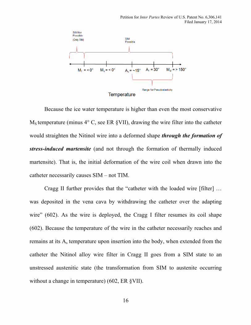
The coil is annealed and then cooled in ice water, at which time it is stressed
into a straightened (i.e., deformed) shape (602). Cragg II provides that the
“transition temperature” (i.e., the Af temperature) is “about 30°C for the alloy used
in this study” (601, ER §VII). Also, because the wire is annealed, the Ms and Mf
temperatures are well below 0° C (ER §VII). Hence, the wire coil disclosed in
Cragg II exhibits the following temperature ranges (ER §VII):
Petition for Inter Partes Review of U.S. Patent No. 6,306,141 Filed January 17, 2014
16
Because the ice water temperature is higher than even the most conservative
MS temperature (minus 4° C, see ER §VII), drawing the wire filter into the catheter
would straighten the Nitinol wire into a deformed shape through the formation of
stress-induced martensite (and not through the formation of thermally induced
martensite). That is, the initial deformation of the wire coil when drawn into the
catheter necessarily causes SIM – not TIM.
Cragg II further provides that the “catheter with the loaded wire [filter] …
was deposited in the vena cava by withdrawing the catheter over the adapting
wire” (602). As the wire is deployed, the Cragg I filter resumes its coil shape
(602). Because the temperature of the wire in the catheter necessarily reaches and
remains at its As temperature upon insertion into the body, when extended from the
catheter the Nitinol alloy wire filter in Cragg II goes from a SIM state to an
unstressed austenitic state (the transformation from SIM to austenite occurring
without a change in temperature) (602, ER §VII).
Petition for Inter Partes Review of U.S. Patent No. 6,306,141 Filed January 17, 2014
17
Further, Cragg II discloses using the pseudoelastic properties of the Nitinol
alloy when repositioning the wire filter. As stated, “[i]f the position of the filter
was not optimal, it could be withdrawn into the catheter and positioned again ….
In two animals, the original placement of the filters was not optimal. These filters
were withdrawn into the catheter and successfully repositioned” (602). This
repositioning thus also discloses that the catheter stresses the Nitinol wire filter
into a deformed shape at body temperature, causing the SMA to transform from
austenite to SIM (ER §VII). Then, when the filter is re-delivered into the body, the
filter is at body temperature and above its As and Af temperatures. This again
Cragg II discloses using a coil wire filter that has a similar configuration to
that of a coil stent. To any extent that Cragg I may not disclose a stent, it would
have been obvious to combine the teachings of Cragg I with the coil wire filter for
the reasons detailed in Dr. Wu’s declaration (e.g., common sense of one ordinary
skill in the art, commercial promise of utilizing Nitinol in medical applications,
promising trial results using Nitinol in stents) (see ER §§VII-VIII).
causes the Nitinol alloy to transform from SIM to unstressed austenite without a
change in temperature. Accordingly, Cragg II contains multiple disclosures
utilizing SIM and a pseudoelastic SMA that meets the limitations of the ’141
Patent Claims (see claim chart below, Section VIII.C.e.).
c. Claims 1-22 are obvious in view of Miyauchi and Cragg I under § 103(a)
Petition for Inter Partes Review of U.S. Patent No. 6,306,141 Filed January 17, 2014
18
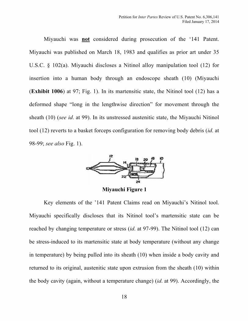
Miyauchi was not
considered during prosecution of the ‘141 Patent.
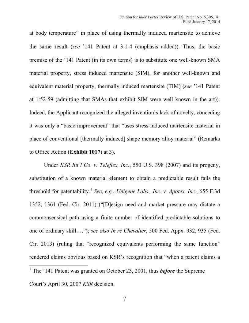
Miyauchi was published on March 18, 1983 and qualifies as prior art under 35
U.S.C. § 102(a). Miyauchi discloses a Nitinol alloy manipulation tool (12) for
insertion into a human body through an endoscope sheath (10) (Miyauchi
(Exhibit 1006) at 97; Fig. 1). In its martensitic state, the Nitinol tool (12) has a
deformed shape “long in the lengthwise direction” for movement through the
sheath (10) (see id. at 99). In its unstressed austenitic state, the Miyauchi Nitinol
tool (12) reverts to a basket forceps configuration for removing body debris (id. at
98-99; see also Fig. 1).
Miyauchi Figure 1
Key elements of the ’141 Patent Claims read on Miyauchi’s Nitinol tool.
Miyauchi specifically discloses that its Nitinol tool’s martensitic state can be
reached by changing temperature or stress (id. at 97-99). The Nitinol tool (12) can
be stress-induced to its martensitic state at body temperature (without any change
in temperature) by being pulled into its sheath (10) when inside a body cavity and
returned to its original, austenitic state upon extrusion from the sheath (10) within
the body cavity (again, without a temperature change) (id. at 99). Accordingly, the
Petition for Inter Partes Review of U.S. Patent No. 6,306,141 Filed January 17, 2014
19
Nitinol tool is pseudoelastic and capable of exhibiting a transformation from SIM
to austenite at body temperature without a change in temperature (ER §§IV-VIII).
Both Miyauchi and Cragg I relate to self-expanding medical devices
deploying shape memory alloy elements used in body cavities. A person of
ordinary skill would have found it obvious to utilize the teachings of Miyauchi for
the placement of a coil stent disclosed in Cragg I as detailed in Dr. Wu’s
declaration (see ER §§VII-VIII). A claim chart follows identifying where each of
the ’141 Patent Claims are disclosed in Miyauchi and Cragg I (Section VIII.C.e.).
d. Claims 1-22 are obvious in view of the ’212 Patent and Cragg I under § 103(a)
The ’212 Patent, granted over twelve years before the priority date for the
’141 Patent, qualifies as prior art under 35 U.S.C. § 102(b). It discloses a self-
expanding contraceptive device made from Nitinol alloy (see, e.g., ’212 Patent
(Exhibit 1007) at Abstract and 2:54-59). The ’212 Patent discloses use of shape
memory alloy elements having Af and As temperatures near or below body
temperature; specifically, the ’212 Patent states that “[t]he devices will reform
when they reach a temperature around body temperature” and “begin reforming at
around 70° F” (’212 Patent at 3:16-21). This means that Af = 37° C (98° F) and As
= 21° C (70° F) (ER §VII). Because the patent discloses that the SMA is annealed
at a high temperature to achieve these As and Af temperatures, it is certain that the
Petition for Inter Partes Review of U.S. Patent No. 6,306,141 Filed January 17, 2014
20
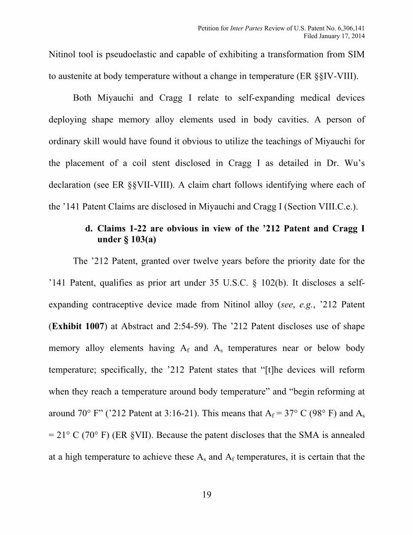
Ms and Mf temperatures are well below 0° C (ER §VII). The temperature
properties of the Nitinol alloy disclosed in the ’212 Patent are as follows:
The ’212 Patent discloses stressing the pseudoelastic SMA device and
constraining it within a cannula (’212 Patent at 2:54—3:15; ER §VII). Further, the
’212 Patent teaches that, because the As temperature is low (i.e., 21° C or 70° F),
the device could be either kept below this temperature or constrained prior to entry
into the body through the cannula (’212 Patent at 3:16-29). Accordingly, the ’212
Patent teaches that above As the Nitinol device will be constrained and will not
expand (ER §VII). Because the device’s As temperature is necessarily reached
upon insertion into the body while in the cannula, the self-expanding medical
device displays stress-induced martensite at body temperature (SIM) (ER §VII). It
then transforms from SIM to its austenite shape without a temperature change (id.).
Both the ’212 Patent and Cragg I relate to self-expanding medical devices
deploying shape memory alloy elements used in body cavities. A person of
Petition for Inter Partes Review of U.S. Patent No. 6,306,141 Filed January 17, 2014
21
ordinary skill would have found it obvious to utilize the teachings of the ’212
Patent for the placement of a coil stent in view of Cragg I (see ER §§VII-VIII). A
claim chart identifying where the ’141 Patent Claims are disclosed in the ’212
Patent and Cragg I follows (Section VIII.C.e.).
e. Claim chart supporting invalidity grounds 1 through 4
’141 Patent Cragg I (Ex. 1004), Cragg II (Ex. 1005), Miyauchi (Ex. 1006), and ’212 Patent (Ex. 1007)
1. A medical device for insertion into a mammalian body, the device comprising:
Cragg I discloses a wire coil stent for insertion into a human body (261). Cragg II discloses a coil filter for insertion into a human body (602). Miyauchi discloses a “manipulation tool” for insertion into a human body (99). The ’212 patent discloses a contraceptive device for insertion into a human body (Abstract).
(a) a hollow placement device;
Cragg I discloses a hollow catheter for placing the coil stent (261). Cragg II discloses a catheter for placing the filter (602). Miyauchi discloses a hollow endoscope for placing the manipulation tool (98). The ’212 patent discloses a hollow cannula (i.e., catheter) for restraining the deformed contraceptive device (3:2-8).
(b) a memory allow element formed at least partly from pseudoelastic shape memory alloy,
The coil stent in Cragg I is made from Nitinol, a pseudoelastic shape memory alloy (261; ER §§VII-VIII). The coil filter in Cragg II is made from Nitinol, a pseudoelastic shape memory alloy (601; ER §§VII-VIII). The manipulation tool in Miyauchi is made from a SMA
Petition for Inter Partes Review of U.S. Patent No. 6,306,141 Filed January 17, 2014
22
that has “so-called ‘pseudoelasticity’ or ‘superelasticity’” (99; ER §§VII-VIII). The ’212 patent discloses a Nitinol pseudoelastic shape memory alloy with an As below body temperature (2:54-59; §§VII-VIII).
the alloy displaying reversible stress-induced martensite at about body temperature such that it has a stress-induced martensitic state and an austenitic state,
At about body temperature (~37° C), the Nitinol disclosed in Cragg I displays a SIM state and an austenitic state (261 (“At or near body temperature the wire transforms into its original shape”); ER §§VII-VIII). The presence of friction in the catheter when inserted into the body confirms this (262; ER §§VII-VIII). At about body temperature, the Nitinol filter in Cragg II has a SIM state and an austenitic state (602; ER §§VII-VIII). When inserted into the body, the Nitinol filter approaches body temperature, which is above As and Af temperatures (ER §§VII-VIII). This causes the filter to display SIM while constrained by the catheter (ER §§VII-VIII). Further, Cragg II discloses that “[i]f the position of the filter [is] not optimal, it [can] be withdrawn into the catheter and positioned again” (602). Doing so causes the filter to again display reversible SIM and austenite at about body temperature (602; ER §§VII-VIII). Miyauchi discloses that “a [pseudoelastic] shape-memory alloy” that “returns to the shape of the usable state, and after a calculus … is captured within a body cavity … is removed [] from the forceps insertion hole … in the direction opposite to the insertion” (99). This removal causes the alloy to be compressed within the endoscope and change from an austenitic state to a SIM state at about body temperature (99; ER §§VII-VIII). The ’212 patent discloses that “[t]he devices will reform when they reach a temperature around body temperature” (3:16-21). Thus, the contraceptive device displays a SIM state and an austenitic state at about body temperature (3:16-29; ER §§VII-VIII). When inserted, the Nitinol device approaches body temperature and displays
Petition for Inter Partes Review of U.S. Patent No. 6,306,141 Filed January 17, 2014
23
reversible SIM while constrained in the cannula (i.e., catheter) (3:16-29; ER §§VII-VIII).
the memory alloy element having (i) a deformed shape when the alloy is in its stress-induced martensitic state and (ii) a different unstressed shape when the alloy is in its austenitic state; and
In Cragg I, the stent is deformed and drawn into a catheter, where it is stressed in a relatively straightened, linear shape (262). When deployed within the body, the Nitinol resumes its unstressed shape (i.e., the stent shown in FIG. 1) (262). The catheter prevents the stent from resuming its original shape, thus keeping it in a SIM state while constrained within the catheter (see 262 (“We also used a … catheter to reduce friction of the partially transformed coil in the catheter.”); ER §§VII-VIII). Cragg II discloses that the filter is straight when in its stress-induced martensitic state and coiled when in its unstressed austenitic state (602; ER §§VII-VIII). Miyauchi discloses that the manipulation tool has a “usable shape” when in its unstressed austenitic state and is deformed into a deformed shape when removed “from the forceps insertion hole … of the endoscope operation portion” (SIM state) (99; ER §§VII-VIII). The ’212 patent discloses that the contraceptive device has a “compact fold configuration” when in its SIM state and a “free shape” or “original shape” when in its unstressed austenitic state (3:2-11; ER §§VII-VIII).
(c) a guide wire; Cragg I discloses that the Nitinol coil is “fastened to a threaded guiding wire” (261). Cragg II discloses that “the filter was … quickly advanced by pushing on the delivery wire” (602). The endoscope disclosed in Miyauchi functions in the same capacity as a guide wire. Based on the teachings of Cragg I, it would have been obvious to modify Miyauchi to place a stent using a guide wire (ER §§VII-VIII). The ’212 patent discloses placing the device in the body through the use of a cannula (1:17-19), which the ’141 Patent views the same as a catheter (see Exhibit 1001 at
Petition for Inter Partes Review of U.S. Patent No. 6,306,141 Filed January 17, 2014
24
5:61-62 (equating devices). Alternatively, it would have been obvious to modify the ’212 Patent to place a stent using a guide wire in view of Cragg I (ER §§VII-VIII).
the memory alloy element being within the hollow placement device,
The Nitinol coil stent in Cragg I is drawn within the hollow catheter for placement (261). The coil filter in Cragg II is within the hollow catheter for placement (601-02). The manipulation tool in Miyauchi is within the hollow endoscope (99 (“[A]t the end … is provided a forceps hole 14 … through which is passed a manipulation tool 12”). The contraceptive device in the ’212 patent is within the hollow cannula (3:2-8).
and the placement device being guidable by the guide wire,
Cragg I discloses that the Nitinol coil is “fastened to a threaded guiding wire to allow accurate placement after being deposited in the aorta” (261). Cragg II discloses that the filter and catheter are “quickly advanced by pushing on the delivery wire” (602). Because Miyauchi discloses the use of an endoscope to position the manipulation tool, it would have been obvious in view of Cragg I to use a guide wire (ER §§VII-VIII). Because the ’212 patent discloses placing the device in the body through the use of a cannula, it would have been obvious in view of the teaching of Cragg I to utilize a guide wire in place of the cannula (ER §§VII-VIII).
the hollow placement device stressing the memory alloy element at a temperature greater than the As of the alloy so that the memory alloy element is in its
The As in Cragg I is 25°C (262, ER §§VII-VIII). When the stent is inserted into the body, the Nitinol stent rises above As, causing the catheter to stress the stent (262; ER §§VII-VIII). The catheter retains the stent in its deformed shape (262 (“We also used a … catheter to reduce friction of the partially transformed coil”); ER §§VII-VIII). The As in Cragg II is ~15° C (601-02; ER §§VII-VIII). When the filter is inserted into the body, the Nitinol filter rises above As, causing the catheter to stress the filter (ER
Petition for Inter Partes Review of U.S. Patent No. 6,306,141 Filed January 17, 2014
25
deformed shape, §§VII-VIII). This stress retains the stent in its deformed shape (602; ER §§VII-VIII). Additionally, the catheter stresses the filter above As when the filter is repositioned by being withdrawn into the catheter (602; ER §§VII-VIII). The As in Miyauchi is ~22° C (99; ER §§VII-VIII). When the manipulation tool is within the endoscope in the body it is at about body temperature, which is above As (99; ER §§VII-VIII). Thus, the stress at a temperature above As causes the tool to deform through SIM (99; ER §§VII-VIII). The ’212 patent discloses that the As of the contraceptive device is 21° C (3:21-25; ER §§VII-VIII). Because of this, the hollow the cannula “retard[s] the reforming of the device [] to its free shape when the device is inserted into the uterus” (3:2-8). The cannula stresses the device and keeps it in a deformed shape at a temperature above As (ER §§VII-VIII).
wherein the memory alloy element can be extended from the hollow placement device by the guide wire at a temperature greater than the As of the alloy to transform at least a portion of the alloy from its stress-induced martensitic state so that the memory alloy element transforms from its deformed shape to its unstressed shape,
Cragg I’s Nitinol stent is “fastened to a threaded guiding wire to allow accurate placement after being deposited in the aorta” (261). As noted, the As is below body temperature. “As the coil is extruded from the catheter … it reverts to its ‘memorized’ shape,” that is, it transforms from its deformed shape to its unstressed shape (262; ER §§VII-VIII). Because As is below body temperature in Cragg II, once the Nitinol is released from the catheter, it “rapidly resume[s] its original filter shape” (602; ER §§VII-VIII). This transforms at least a portion of the alloy from SIM to austenite (ER §§VII-VIII). Similarly, Cragg II discloses that the filter is extended from the catheter above As and also transforms from its deformed, stress-induced martensitic shape to its unstressed austenitic shape after repositioning (602; ER §§VII-VIII). Miyauchi discloses that the reverse transformation range (i.e., the As and Af temperatures) can be between 30-50° C
Petition for Inter Partes Review of U.S. Patent No. 6,306,141 Filed January 17, 2014
26
(99; ER §§VII-VIII). Miyauchi discloses deploying the SMA device from the endoscope (i.e., hollow placement device) at a temperature that is greater than the As temperature of the tool (99; ER §§VII-VIII). Doing so causes a transformation from SIM to austenite while above the As of the manipulation tool (99; ER §§VII-VIII). It would have been obvious in view of Cragg I to utilize a guide wire to deploy a stent (ER §§VII-VIII). The ’212 patent discloses that the As of the contraceptive device is well below body temperature (3:21-25; ER §§VII-VIII). When extended from the cannula (catheter) at body temperature, the device transforms from SIM to austenite (hence transforming from its deformed shape to its unstressed shape) (ER §§VII-VIII). It would have been obvious in view of Cragg I to utilize a guide wire to deploy a stent (ER §§VII-VIII).
and wherein the alloy is selected so that the transformation can occur without any change in temperature of the placement device or the memory alloy element.
The As in Cragg I is 25°C and the Af is “at or near body temperature” (261-62, ER §§VII-VIII). The Nitinol coil in Cragg I thus does not require any change in the temperature of the catheter or the Nitinol stent in order for the stent to transform from SIM to austenite when inside the body (ER §§VII-VIII). Cragg II discloses that the temperature in the body is above the Nitinol filter’s As temperature (602; ER §§VII-VIII). The filter thus transforms from a deformed, stressed shape to an unstressed shape without requiring any change in temperature when it is released from the catheter (ER §§VII-VIII). Miyauchi discloses that its shape memory alloy does not require any change in temperature for the material to exhibit a pseudoelastic effect (99; ER §§VII-VIII). Because the As temperature in Miyauchi is below body temperature, the manipulation tool exhibits pseudoelasticity at body temperature, allowing it to repeatedly transform from SIM to austenite without requiring any change in temperature (99-100; ER §§VII-VIII).
Petition for Inter Partes Review of U.S. Patent No. 6,306,141 Filed January 17, 2014
27
The ’212 patent discloses that the As is below body temperature (3:21-25). As such, the SMA device transforms in the body from a deformed SIM state to an austenitic, unstressed state that occurs without requiring any change in temperature of the device (3:21-25; ER §§VII-VIII).
2. The device of claim 1, wherein the memory alloy element is a stent.
Cragg I discloses that the wire coil graft “could be used as [a] stent[] to maintain vessel patency” (262). Cragg II discloses a Nitinol wire coil graft, which can be used as a stent to maintain vessel patency (or it would have been obvious to do so in view of Cragg I) (601; ER VII). Miyauchi shows a SMA device (manipulator 12) having a coiled structure similar to the stent of Cragg I in FIGS. 3(A)-3(C). It would have would have been obvious to alter Miyauchi to deploy a coil stent in view of Cragg I (ER §§VII-VIII). As already noted, it would have would have been obvious to modify the ’212 patent to deploy a coil stent using a catheter and guide wire in view of Cragg I and other knowledge in the art (ER §§VII-VIII).
3. The device of claim 2, including a guide wire for endarterial placement of a stent graft.
Cragg I discloses that its Nitinol coil is “fastened to a threaded guiding wire to allow accurate placement” (261). The wire coil filter in Cragg II is endarterially placed by a guide wire (602 “[A] delivery wire was screwed to the filter …. The filter was deposited in the vena cava by withdrawing the catheter over the adapting wire”)). As previously noted, it would have been obvious to one of ordinary skill in the art to modify the teachings disclosed in Miyauchi and the ’212 patent to deploy a self-expanding stent through the use of a catheter and guide wire (ER §§VII-VIII).
4. The invention of claim 1 wherein the
The Teflon catheter (i.e., placement device) in Cragg I does not exhibit a state change (262, ER §§VII-VIII).
Petition for Inter Partes Review of U.S. Patent No. 6,306,141 Filed January 17, 2014
28
transformation occurs without any change in the state of the placement device.
The Teflon catheter in Cragg II does not exhibit a state change (602, ER §§VII-VIII). The endoscope in Miyauchi does not exhibit a state change (99; ER §§VII-VIII). The cannula in the ’212 patent does not exhibit a state change (1:17-19; ER §§VII-VIII).
5. The device of claim 1, wherein the hollow placement device is a catheter.
Cragg I discloses that the hollow placement device is a “10-F Teflon catheter” (261). Cragg II provides that “[t]he catheter with the loaded nitinol wire was inserted … and passed … to the desired level in the inferior vena cava” (602). As previously noted, it would have been obvious to one of ordinary skill in the art to modify the teachings disclosed in Miyauchi to deploy a self-expanding stent through the use of a hollow catheter and guide wire (ER VII). The ’212 patent discloses that the hollow placement device is a catheter (3:2-10). The’141 Patent equates a cannula to a catheter (Exhibit 1001 at 5:61-62).
6. A medical device which comprises:
Cragg I, Cragg II, Miyauchi and the ’212 patent each disclose a medical device for insertion into a human body (see Claim 1).
(a) a stent for endarterial placement within a human body so that the stent is substantially at human body temperature,
Cragg I discloses a wire coil stent for endarterial placement substantially at human body temperature (262 (“Loosely wound coils could be used as stents to maintain vessel patency”)). Cragg II discloses a wire coil filter for endarterial placement substantially at human body temperature (601-02). The wire coil can be used as a stent for endarterial placement (or it would have been obvious to do so in view of Cragg I) (601; ER §§VII-VIII). It would have been obvious to adapt the uses of shape-memory alloys as disclosed in Miyauchi and the ’212
Petition for Inter Partes Review of U.S. Patent No. 6,306,141 Filed January 17, 2014
29
patent to endarterially place a stent within a human body in view of Cragg I (ER §§VII-VIII).
the stent comprising a shape memory alloy which displays stress-induced martensite behavior at body temperature; and
At about body temperature (~37° C), the Nitinol disclosed in Cragg I displays a SIM state and an austenitic state (261 (“At or near body temperature the wire transforms into its original shape”), ER §§VII-VIII). The presence of friction in the catheter when inserted into the body confirms this (262; ER §§VII-VIII). At about body temperature, the Nitinol filter in Cragg II has a SIM state and an austenitic state (602; ER §§VII-VIII). When inserted, the Nitinol filter approaches body temperature, which is above As and Af temperatures (ER §§VII-VIII). This causes the filter to display SIM at about body temperature while constrained by the catheter (ER VII). Further, Cragg II discloses that “[i]f the position of the filter [is] not optimal, it [can] be withdrawn into the catheter and positioned again” (602). Doing so causes the filter to again display reversible SIM and austenite at about body temperature (602; ER §§VII-VIII). Miyauchi discloses that “a [pseudoelastic] shape-memory alloy” that “returns to the shape of the usable state, and after a calculus … is captured within a body cavity … is removed [] from the forceps insertion hole … in the direction opposite to the insertion” (99). This removal causes the alloy to be compressed within the endoscope and change from an austenitic state to a SIM state at about body temperature (99; ER §§VII-VIII). The ’212 patent discloses that “[t]he devices will reform when they reach a temperature around body temperature” (3:16-21). The contraceptive device displays a SIM state and an austenitic state at about body temperature (3:16-29; ER §§VII-VIII). When inserted, the device approaches body temperature and displays reversible SIM while constrained by the cannula (3:16-29; ER §§VII-VIII).
(b) a restraint holding the stent in a deformed
The As in Cragg I is 25°C (262, ER §§VII-VIII). When the stent is inserted into the body, the Nitinol stent rises above As, causing the catheter to stress the stent and retain
Petition for Inter Partes Review of U.S. Patent No. 6,306,141 Filed January 17, 2014
30
configuration at a temperature less than the body temperature of the human for endarterial positioning of the stent within the body in its deformed configuration,
the stent in its SIM state (262, ER §§VII-VIII). The catheter retains the stent in this deformed shape above As (262; ER §§VII-VIII). The catheter also holds the stent in this deformed configuration at a temperature that is less than body temperature for a time as it is being endarterially positioned (261, ER §§VII-VIII). The As in Cragg II is ~15° C (601-02; ER §§VII-VIII). When the filter is inserted into the body, the Nitinol filter rises above As, causing the catheter to stress the filter and the filter to retain its SIM state (ER §§VII-VIII). This stress retains the filter in its deformed shape less than body temperature for a period of time while it is endarterially positioned (602; ER §§VII-VIII). The As in Miyauchi is ~22° C (99; ER §§VII-VIII). Miyauchi discloses that, “[i]f the reverse transformation temperature is low, the manipulation tool 12 is cooled in advance, and during use it is immediately inserted into the tube-shaped path” (99). For the period of time from when the tool reaches its As temperature and up to body temperature, the restraints holds the device in a deformed configuration below body temperature while the tool is positioned (99; ER §§VII-VIII). The ’212 patent teaches that because “the device will begin reforming around 70° F [21° C],” it is “important to keep the device always below 70° F before insertion into a uterus, or alternatively to keep the device in a container which will hold the deformed shape” (3:21-25). This discloses that the device is deformed while its temperature is below body temperature (ER §§VII-VIII). As noted, it would have been obvious to adapt the uses of shape-memory alloys as disclosed in Miyauchi and the ’212 patent to endarterially place a stent in view of Cragg I (ER §§VII-VIII).
the deformation occurring through the formation of
Because the Nitinol coil wire in Cragg I is annealed, it has a Ms temperature well below 0° C (261, ER §§VII-VIII). The deformation is thus due to SIM (261, ER §§VII-VIII).
Petition for Inter Partes Review of U.S. Patent No. 6,306,141 Filed January 17, 2014
31
stress-induced martensite;
The filter in Cragg II has a Ms temperature well below 0° C (ER §§VII-VIII). The deformation is thus due to SIM (601; ER §§VII-VIII). Further, the stress of the catheter causes SIM when the Nitinol stent is repositioned within the body (601-02; ER §§VII-VIII). Because As is below body temperature and Ms is below 0° C, the deformation in Miyauchi is through the formation of SIM (99; ER §§VII-VIII; see also Claim 1). Because As is below body temperature and Ms below 0° C, the deformation in the ’212 Patent is through the formation of SIM (3:21-25; ER §§VII-VIII; see also Claim 1).
wherein the stent is sufficiently deformed that when the stent is at human body temperature removal of the restraint from the stent, without change in temperature of the device, releases at least a portion of the stent from its deformed configuration.
Cragg I discloses that, when deployed from the catheter, the Nitinol transforms from its deformed to its unstressed configuration (261; ER §§VII-VIII). Because the Nitinol wire is released at body temperature, it undergoes this transformation without change in temperature of the device (261; ER §§VII-VIII). Cragg II discloses that the temperature in the body is above the Nitinol filter’s As temperature (602; ER §§VII-VIII). The filter thus transforms from a deformed, stressed shape to an unstressed shape without any change in temperature when it is released at body temperature from the catheter (ER §§VII-VIII). Miyauchi discloses that its SMA does not require any change in temperature for the material to exhibit a pseudoelastic effect (99; ER §§VII-VIII). Because the As temperature in Miyauchi is below body temperature, the manipulation tool transforms from a deformed shape to a usable shape when released within the body without change in temperature (99-100; ER §§VII-VIII). The ’212 patent discloses that the As is below body temperature (3:21-25). As such, the alloy transforms from a deformed SIM state to an austenitic, unstressed shape
Petition for Inter Partes Review of U.S. Patent No. 6,306,141 Filed January 17, 2014
32
above As that occurs without change in temperature when released at body temperature (3:21-25; ER §§VII-VIII).
7. A device as claimed in claim 6, in which the restraint is hollow, and the stent is positioned at least partially within the restraint.
The catheter (i.e., restraint) in Cragg I is hollow and the wire coil is positioned within the catheter (261). The catheter (i.e., restraint) in Cragg II is hollow and the wire coil is positioned within the catheter (601). The endoscope (i.e., restraint) in Miyauchi is hollow and the self-expanding medical device is positioned within the endoscope (99). It would have been obvious to use a stent in view of Cragg I (ER §§VII-VIII). The cannula (i.e., restraint) in the ’212 patent is hollow and the self-expanding medical device is positioned within the cannula (3:16-29). It would have been obvious to use a stent in view of Cragg I (ER §§VII-VIII).
8. A device as claimed in claim 6 or 7, in which the restraint is a catheter.
The restraint in Cragg I is a catheter (261). The restraint in Cragg II is a catheter (601). It would have been obvious to utilize a catheter in Miyauchi in view of Cragg I (ER VII). The cannula in the ’212 patent is the same as a catheter (Exhibit 1001 at 5:61-62).
9. A device as claimed in 6 or 7, in which the stent has a transverse dimension and a longitudinal dimension, and wherein the stent is deformed by its transverse dimension being reduced, and wherein the restraint prevents the
The Nitinol wire coil in Cragg I has a transverse dimension (diameter of coil) and longitudinal dimension (length) (261, FIG. 1). While within the catheter, the stent’s transverse dimension is reduced by deformation (262; ER §§VII-VIII). The catheter prevents transverse expansion of the stent) (262; ER §§VII-VIII). The Nitinol wire coil in Cragg II has a transverse dimension (diameter of coil) and longitudinal dimension (length) (602, FIG. 1B). While within the catheter, the wire coil is deformed by its transverse dimension being reduced and constrained therein (602; ER §§VII-VIII). Miyauchi discloses a coil-like medical device with a
Petition for Inter Partes Review of U.S. Patent No. 6,306,141 Filed January 17, 2014
33
transverse expansion of the stent.
transverse dimension (diameter of coil) and longitudinal dimension (99, FIGS 3(A)-3(C)). The coil is deformed by its transverse dimension and prevented from expanding as shown in FIG. 4 (99; ER §§VII-VIII). As already noted, it would have been obvious to use a stent. The medical device disclosed in the ’212 patent has a transverse (across) dimension and a longitudinal (length) dimension as shown in FIG. 7. When deformed (see FIG. 8), the transverse dimension is reduced and prevented from expanding by the cannula. As already noted, it would have been obvious to use a stent in view of Cragg I.
10. The device of claim 6, wherein the shape memory alloy element is sufficiently deformed that removal of the restraint from the shape memory alloy releases at least a portion of the shape memory alloy element from its deformed configuration without change in state of the restraint.
The Teflon catheter in Cragg I does not exhibit a state change (262; ER §§VII-VIII). The Teflon catheter in Cragg II does not exhibit a state change (602, ER §§VII-VIII). The endoscope in Miyauchi does not exhibit a state change (99; ER §§VII-VIII). The cannula in the ’212 patent does not exhibit a state change (1:17-19; ER §§VII-VIII).
11. A medical device suitable for placement within a mammalian body for treatment of the mammalian body, the device comprising:
Cragg I, Cragg II, Miyauchi and the ’212 patent each disclose a medical device for insertion into and treatment of a human body (see Claim 1).
(a) a stent formed at least partly from a pseudoelastic shape-
The coil stent in Cragg I is made from Nitinol, a pseudoelastic shape memory alloy (261, ER §§VII-VIII).
Petition for Inter Partes Review of U.S. Patent No. 6,306,141 Filed January 17, 2014
34
memory alloy, The coil filter in Cragg II is made from Nitinol, a pseudoelastic shape memory alloy (601; ER §§VII-VIII). The manipulation tool in Miyauchi is made from a SMA that exhibits “‘pseudoelasticity’ or ‘superelasticity’” (99; ER §§VII-VIII). It would have been obvious to utilize a stent in view of Cragg I (ER §§VII-VIII). The ’212 patent discloses a Nitinol pseudoelastic SMA with an As below body temperature (2:54-59; ER §§VII-VIII). It would have been obvious to utilize a stent in view of Cragg I (ER §§VII-VIII).
the alloy having a reversible stress-induced martensitic state and an austenitic state,
The Nitinol disclosed in Cragg I displays a SIM state and an austenitic state above As (261; ER §§VII-VIII; see Claims 1 and 6). The Nitinol filter in Cragg II displays a SIM state and an austenitic state above As (602; ER §§VII-VIII; see Claims 1 and 6). Miyauchi discloses a pseudoelastic SMA that exhibits SIM and austenitic states above As temperature (99; ER §§VII-VIII; see Claims 1 and 6). The ’212 patent discloses a pseudoelastic SMA that exhibits stress-induced martensitic and austenitic states above As (3:16-21; ER §§VII-VIII; see Claims 1 and 6).
the memory alloy element having (i) a deformed shape when the alloy is in its stress-induced martensitic state and (ii) a different, unstressed shape; and
In Cragg I, the stent is deformed and drawn into a catheter, where it is stressed in a relatively straightened shape (262). When removed, the Nitinol takes the shape of a coil stent (262, FIG. 1). The catheter keeps the stent in a deformed SIM state (262; ER §§VII-VIII; see also Claim 1). Cragg II discloses that the filter is straight when in its SIM state and coiled when in its unstressed austenitic state (602; ER §§VII-VIII). Miyauchi discloses that the manipulation tool has a “usable shape” when in its unstressed state and has a
Petition for Inter Partes Review of U.S. Patent No. 6,306,141 Filed January 17, 2014
35
deformed SIM shape, e.g., when removed “from the … insertion hole” (99; ER §§VII-VIII). The ’212 patent discloses that the contraceptive device has a “compact fold configuration” when in its SIM state and a “free shape” or “original shape” when in its unstressed austenitic state (3:2-11; ER §§VII-VIII).
(b) restraining means engaging and stressing the stent at a temperature less than the body temperature of the mammal and greater than the As of the alloy for positioning the stent within the mammalian body while the stent is in its deformed shape;
The As in Cragg I is 25°C (262, ER §§VII-VIII). When the stent is inserted into the body, the Nitinol stent rises above As, causing the catheter to stress the stent and retain SIM (262, ER §§VII-VIII). Thus, the temperature of the stent while restrained in the catheter is above As but less than body temperature for a time as it is positioned within the body (262, ER §§VII-VIII; see Claim 6). The As in Cragg II is ~15° C (601-02; ER §§VII-VIII). When the filter is inserted into the body, the Nitinol filter rises above As, causing the catheter to stress the filter and retain SIM (602; ER §§VII-VIII). Thus, the temperature of the filter while restrained is above As but less than body temperature for a time as it is positioned within the body (602; ER §§VII-VIII; see Claim 6). The As in Miyauchi is ~22° C (99; ER §§VII-VIII). For the period of time from when the tool reaches its As temperature and prior to reaching body temperature, the restraint will hold the device in a deformed configuration below body temperature while the tool is positioned within the body (99; ER VII; see Claim 6). The ’212 patent discloses that the self-expanding medical device will be in its deformed configuration for a time while its temperature is below body temperature but above its As temperature when being positioned in the body (ER §§VII-VIII; see Claim 6).
wherein the alloy is selected so that removal of the restraining means from the stent at a
The As temperature of the Nitinol wire in Cragg I is below body temperature. “As the coil is extruded from the catheter … it reverts to its ‘memorized’ shape” (i.e., it transforms from its relatively straight shape to its coil shape) (262; ER §§VII-VIII; see Claim 1).
Petition for Inter Partes Review of U.S. Patent No. 6,306,141 Filed January 17, 2014
36
temperature greater than the As of the alloy when the device is placed within the mammalian body, transforms at least a portion of the alloy from its stressed-induced martensitic state so that the stent transforms from its deformed relatively straightened shape towards its unstressed relatively coiled shape,
Because As is below body temperature in Cragg II, once the Nitinol is released from the catheter, it “rapidly resume[s] its original filter shape” (602; ER §§VII-VIII). This transforms at least a portion of the alloy from SIM to austenite (ER §§VII-VIII). Cragg II also discloses that the filter transforms from its SIM shape to its unstressed austenitic shape after repositioning (602; ER §§VII-VIII; see Claim 1). Miyauchi discloses deploying the SMA device from the endoscope at a temperature that is greater than the As temperature of the tool (99; ER §§VII-VIII). Doing so causes a transformation from SIM to austenite (99; ER §§VII-VIII; see Claim 1). The ’212 patent discloses that the As of the device is below body temperature (3:21-25; ER §§VII-VIII). When extended from the cannula at body temperature, the device transforms from SIM to austenite (ER §§VII-VIII).
without any change in temperature of the restraining means or the stent being required for the transformation of the alloy.
The Nitinol in Cragg I does not require any change in the temperature of the catheter or the stent in order for the stent to transform from SIM to austenite when released inside the body (261-62; ER §§VII-VIII; see Claim 1). The Nitinol coil in Cragg II does not require any change in temperature of the catheter or the stent in order for the stent to transform from SIM to austenite when released inside the body (601-02; ER §§VII-VIII; see Claim 1). Miyauchi discloses that its SMA does not require any change in temperature for the material to change from SIM to austenite in the body (99; ER §§VII-VIII; see Claim 1). The ’212 patent discloses an SMA that does not require a change in temperature to transform from a deformed SIM state to an austenitic shape inside the body (3:21-25; ER §§VII-VIII; see Claim 1).
12. The device of claim 11, wherein
The Teflon catheter in Cragg I does not exhibit a state change (262; ER §§VII-VIII).
Petition for Inter Partes Review of U.S. Patent No. 6,306,141 Filed January 17, 2014
37
the transformation of the alloy occurs without any change in the state of the restraining means.
The Teflon catheter in Cragg II does not exhibit a state change (602, ER §§VII-VIII). The endoscope in Miyauchi does not exhibit a state change (99; ER §§VII-VIII). The cannula in the ’212 patent does not exhibit a state change (1:17-19; ER §§VII-VIII).
13. The device of claim 11 wherein the restraining means is a catheter.
The restraining means in Cragg I is a catheter (261). The restraining means in Cragg II is a catheter (601). It would have been obvious to utilize a catheter in Miyauchi in view of Cragg I (ER §§VII-VIII). The cannula in the ’212 patent is the same as a catheter (Exhibit 1001 at 5:61-62).
14. The device of claim 13 wherein the stent is within the catheter.
The catheter in Cragg I is hollow and the wire coil is positioned within the catheter (261). The catheter in Cragg II is hollow and the wire coil is positioned within the catheter (601). The endoscope in Miyauchi is hollow and the device is positioned therein. It would have been obvious to use a stent in view of Cragg I (ER §§VII-VIII). The cannula in the ’212 patent is hollow and the device is positioned therein (3:16-29). It would have been obvious to utilize a stent in view of Cragg I (ER §§VII-VIII).
15. A medical device for treatment of a mammalian body, the device comprising:
Cragg I, Cragg II, Miyauchi and the ’212 patent each disclose a medical device for insertion into and treatment of a human body (see Claim 1).
(a) a memory alloy stent formed at least partly from a pseudoelastic shape-
The coil stent in Cragg I is made from Nitinol, a pseudoelastic SMA (261, ER §§VII-VIII). The coil filter in Cragg II is made from Nitinol, a
Petition for Inter Partes Review of U.S. Patent No. 6,306,141 Filed January 17, 2014
38
memory alloy, pseudoelastic SMA (601; ER §§VII-VIII). The manipulation tool in Miyauchi is made from a SMA that exhibits “‘pseudoelasticity’ or ‘superelasticity’” (99; ER §§VII-VIII). As previously noted, it would have been obvious to utilize a stent in view of Cragg I. The ’212 patent discloses a pseudoelastic SMA with an As below body temperature (2:54-59; ER §§VII-VIII). As already noted, it would have been obvious to utilize a stent using the teachings of the ’212 Patent in view of Cragg I.
the alloy displaying reversible stress-induced martensite at about the mammalian body temperature such that it has a stress-induced martensitic state and an austenitic state,
At body temperature (above As), the Nitinol stent in Cragg I displays SIM and austenitic states (261; ER §§VII-VIII; see Claims 1 and 6). At body temperature (above As), the Nitinol filter in Cragg II displays SIM and austenitic states (602; ER §§VII-VIII; see Claims 1 and 6). Miyauchi discloses a SMA that exhibits SIM and austenitic states at about body temperature (which is above As) (99; ER §§VII-VIII; see Claims 1 and 6). The ’212 patent discloses a SMA that exhibits SIM and austenitic states at about body temperature (above As) (3:16-21; ER §§VII-VIII; see Claims 1 and 6).
the memory alloy stent having (i) a deformed relatively straightened shape when the alloy is in its stress-induced martensitic state and (ii) a different unstressed relatively coiled shape;
In Cragg I, the stent is deformed and drawn into a catheter, where it is stressed in a relatively straightened shape (262). When removed from the catheter, the Nitinol takes the shape of a coil stent (262, FIG. 1). The catheter keeps the stent in a SIM state while the Nitinol is constrained within the catheter (262; ER §§VII-VIII; see Claim 1). Cragg II discloses that the filter is straight when constrained in the catheter in its SIM state and coiled when in its unstressed austenitic state (602; ER §§VII-VIII). Miyauchi discloses that the manipulation tool has a
Petition for Inter Partes Review of U.S. Patent No. 6,306,141 Filed January 17, 2014
39
“usable shape” when in its unstressed state and has a deformed SIM shape, e.g., when removed “from the … insertion hole” (99; ER §§VII-VIII). The ’212 patent discloses that the contraceptive device has a “compact fold configuration” when in its SIM state and a “free shape” or “original shape” when in its unstressed austenitic state (3:2-11; ER §§VII-VIII).
(b) a hollow restraining member with the memory alloy stent being within the restraining member,
Cragg I discloses a catheter (i.e., restraining member) with the stent being placed therein (261). The catheter in Cragg II is hollow and the wire coil is positioned therein (601). The endoscope in Miyauchi is hollow and the device is positioned therein (99). It would have been obvious to utilize a stent in view of Cragg I (ER §§VII-VIII). The cannula in the ’212 Patent is hollow and the device is positioned therein (3:16-29). It would have been obvious to utilize a stent in view of Cragg I (ER §§VII-VIII).
the restraining member engaging and stressing the memory alloy stent at a temperature less than the body temperature of the mammal and greater than the As of the alloy for positioning the memory alloy stent within the human body while the memory alloy coil stent is in its deformed relatively straightened shape;
The As in Cragg I is 25°C (262, ER §§VII-VIII). When the stent is inserted into the body, the Nitinol stent rises above As, causing the catheter to stress the stent and retain SIM (262, ER §§VII-VIII). Thus, the temperature of the stent while restrained in the catheter is above As but less than body temperature for a time as it is positioned within the body (262, ER §§VII-VIII; see Claims 6 and 11). The As in Cragg II is ~15° C (601-02; ER §§VII-VIII). When the filter is inserted into the body, the Nitinol filter rises above As, causing the catheter to stress the filter and retain SIM (602; ER §§VII-VIII). Thus, the temperature of the filter while restrained is above As but less than body temperature for a time as it is positioned within the body (602; ER §§VII-VIII; see Claims 6 and 11). The As in Miyauchi is ~22° C (99; ER §§VII-VIII). For the period of time from when the tool reaches its As temperature and prior to reaching body temperature, the
Petition for Inter Partes Review of U.S. Patent No. 6,306,141 Filed January 17, 2014
40
restraint will hold the device in a deformed configuration below body temperature while the tool is positioned within the body (99; ER VII; see Claims 6 and 11). The ’212 patent discloses that the self-expanding medical device will be in its deformed configuration for a time while its temperature is below body temperature but above its As temperature when being positioned in the body (ER §§VII-VIII; see Claims 6 and 11).
wherein the restraining member and the memory alloy stent are movable relative to each other to transform at least a portion of the alloy from its stress-induced martensitic state at a temperature greater than the As of the alloy so that the memory alloy element transforms from its deformed shape towards its unstressed relatively coiled shape,
The As temperature of the Nitinol wire in Cragg I is below body temperature. “As the coil is extruded from the catheter … it reverts to its ‘memorized’ shape” (i.e., it transforms from its relatively straight shape to its coil shape) (262; ER §§VII-VIII; see Claim 1). Because As is below body temperature in Cragg II, once the stent is released from the catheter, it “rapidly resume[s] its original filter shape” (602; ER §§VII-VIII). This transforms at least a portion of the alloy from SIM to austenite (ER §§VII-VIII). Similarly, Cragg II discloses that the filter transforms from its deformed, SIM shape to its unstressed austenitic shape after repositioning (602; ER §§VII-VIII; see Claim 1). Miyauchi discloses deploying the SMA device from the endoscope at a temperature greater than the As temperature of the device (99; ER §§VII-VIII). Doing so causes a transformation from SIM to austenite (99; ER §§VII-VIII; see Claim 1). The ’212 patent discloses that the As of the contraceptive device is well below body temperature (3:21-25; ER §§VII-VIII). Thus, when extended from the cannula, the device transforms from SIM to austenite (ER §§VII-VIII).
and wherein the alloy is selected so that the transformation can occur without any change in
The SMA selected in Cragg I can change from SIM to austenite when released in the body without change in temperature (261-62; ER §§VII-VIII; see Claim 1). The SMA selected in Cragg II can transform from SIM to austenite when released in the body without change in
Petition for Inter Partes Review of U.S. Patent No. 6,306,141 Filed January 17, 2014
41
temperature of the restraining member of the memory alloy element.
temperature (601-02; ER §§VII-VIII; see Claim 1). The SMA selected in Miyauchi can transform from SIM to austenite when released in the body without change in temperature (99; ER §§VII-VIII; see Claim 1). The SMA selected in the ’212 patent can transform from SIM to austenite when released in the body without change in temperature (3:21-25; ER §§VII-VIII; see Claim 1).
16. A medical device suitable for placement within a mammalian body for treatment of the mammalian body,
Cragg I, Cragg II, Miyauchi and the ’212 patent each disclose a medical device for insertion into and treatment of a human body (see Claim 1).
the device comprising (i) a restraint, and (ii) a coil stent formed at least partly from a pseudoelastic shape-memory alloy,
Cragg I discloses a catheter with a deformed Nitinol coil being placed therein (261). The Nitinol coil is a pseudoelastic SMA (261; ER §§VII-VIII). Cragg II discloses a catheter with a deformed Nitinol coil being placed therein (601). The filter in Cragg II is made from Nitinol, a pseudoelastic SMA (601; ER §§VII-VIII). The manipulation tool in Miyauchi is constrained within an endoscope and made from a SMA that exhibits “‘pseudoelasticity’” (99; ER §§VII-VIII). As discussed, it would have been obvious to use a stent in view of Cragg I. The ’212 patent discloses a Nitinol pseudoelastic SMA with an As below body temperature constrained within a cannula (2:54-59; ER §§VII-VIII). As discussed, it would have been obvious to utilize a stent in view of Cragg I.
the alloy displaying reversible stress-induced martensite by being above its As and above its Ms and below its Md at about body
The catheter in Cragg I holds the wire coil in a deformed configuration (262; ER §§VII-VIII). The As temperature for the Nitinol is below body temperature, the Ms temperature is less than 0° C, and the Md temperature is approximately 150° C (ER §§VII-VIII). At body temperature, the SMA displays reversible SIM by being above its Ms and As and below its Md temperature (ER
Petition for Inter Partes Review of U.S. Patent No. 6,306,141 Filed January 17, 2014
42
temperature; §§VII-VIII). The catheter in Cragg II holds the wire coil in a deformed configuration (601-02; ER §§VII-VIII). The As temperature is below body temperature, the Ms temperature is less than 0° C, and the Md temperature is ~150° C (ER §§VII-VIII). At body temperature, the alloy displays reversible SIM by being above its Ms and As and below its Md temperature (ER §§VII-VIII). Miyauchi discloses stressing the manipulation tool above the As temperature of the SMA during insertion into the body (99; ER §§VII-VIII). The Ms temperature is below body temperature, and the Md temperature is above body temperature (ER §§VII-VIII). Thus, the SMA displays reversible SIM at about body temperature (ER §§VII-VIII). In the ’212 patent, the temperature of the device exceeds the As of the device upon insertion into the body (3:2-8; ER §§VII-VIII). Body temperature is above Ms and below Md for the SMA disclosed in the ’212 patent, thus providing for reversible SIM at about body temperature (ER §§VII-VIII).
such that it has a stress-induced martensitic state and an austenitic state,
Above its As temperature, the Nitinol in Cragg I displays a SIM state and an austenitic state (261; ER §§VII-VIII; see Claim 1). Above its As temperature, the Nitinol in Cragg II displays a SIM state and an austenitic state (602; ER §§VII-VIII; see Claim 1). Miyauchi discloses a pseudoelastic SMA that exhibits SIM and austenitic states above its As temperature (99; ER §§VII-VIII; see Claim 1). The ’212 patent discloses a pseudoelastic SMA that exhibits SIM and austenitic states above its As temperature (3:16-21; ER §§VII-VIII; see Claim 1).
the element having In Cragg I, the stent is deformed and drawn into a catheter,
Petition for Inter Partes Review of U.S. Patent No. 6,306,141 Filed January 17, 2014
43
(i) a relatively straightened shape when the alloy is in its stress-induced martensitic state and (ii) a different relatively coiled shape;
where it is stressed in a relatively straightened shape (262). When removed from the catheter, the Nitinol takes the shape of a coil stent (262, FIG. 1). The catheter keeps it in a SIM state while the Nitinol is constrained within the catheter (262; ER §§VII-VIII; see Claim 1). Cragg II discloses that the filter is relatively straight when in its SIM state and coiled when in its unstressed austenitic state (602; ER §§VII-VIII). Miyauchi discloses that the manipulation tool has a “usable shape” of a coil when in its austenitic state and a linear, relatively straight shape when deformed by SIM in the endoscope (99, FIG. 3; ER §§VII-VIII). The ’212 patent discloses that the contraceptive device has a “compact fold configuration” when in its SIM state and a “free shape” or “original shape” when in its unstressed austenitic state (3:2-11; ER §§VII-VIII).
wherein the restraint is (i) stressing the coil stent at a temperature less than the body temperature of the mammal for placement of the coil stent in its relatively straightened shape in the mammalian body and
The As in Cragg I is 25°C (262, ER §§VII-VIII). When the stent is inserted into the body, the Nitinol stent rises above As, causing the catheter to stress the stent and retain SIM (262, ER §§VII-VIII). Thus, the temperature of the stent while restrained in the catheter is above As but less than body temperature for a time as it is positioned (262, ER §§VII-VIII; see Claims 6, 11, and 15). The As in Cragg II is ~15° C (601-02; ER §§VII-VIII). When the filter is inserted into the body, the Nitinol filter rises above As, causing the catheter to stress the filter and retain SIM (602; ER §§VII-VIII). Thus, the temperature of the filter while restrained is above As but less than body temperature for a time as it is positioned within the body (602; ER §§VII-VIII; see Claims 6, 11, and 15). The As in Miyauchi is ~22° C (99; ER §§VII-VIII). For the period of time from when the tool reaches its As temperature and prior to reaching body temperature, the restraint will hold the device in a deformed configuration below body temperature while the tool is positioned within
Petition for Inter Partes Review of U.S. Patent No. 6,306,141 Filed January 17, 2014
44
the body (99; ER VII; see Claims 6, 11, and 15). The ’212 patent discloses that the self-expanding medical device will be in its deformed configuration for a time while its temperature is below body temperature but above its As temperature when being positioned in the body (ER §§VII-VIII; see Claims 6, 11, and 15).
(ii) is capable of being at least partially removed from the coil stent while the coil stent is within the body at the body temperature and the coil stent is therefore at an operating temperature greater than the As and Ms and below the Md of the alloy,
The As temperature of the wire in Cragg I is below body temperature. “As the coil is extruded from the catheter … it reverts to its ‘memorized’ shape” (i.e., it transforms from its relatively straight shape to its coil shape) (262; ER §§VII-VIII). This operating temperature at release (i.e., body temperature) is greater than the As and Ms temperatures and below the Md temperature (ER §§VII-VIII; see Claims 1 and 6). Because As is below body temperature in Cragg II, once the filter is released from the catheter, it “rapidly resume[s] its original filter shape” (602; ER §§VII-VIII). This operating temperature at release (i.e., body temperature) is greater than the As and Ms temperatures and below the Md temperature (ER §§VII-VIII; see Claims 1 and 6). Miyauchi discloses deploying the SMA at body temperature (99; ER §§VII-VIII). This operating temperature for the transformation (i.e., body temperature) is greater than the As and Ms temperatures and below the Md temperature (ER §§VII-VIII; see Claims 1 and 6). The ’212 patent discloses deploying the SMA at body temperature (3:21-25; ER VII). This operating temperature for the transformation (i.e., body temperature) is greater than the As and Ms temperatures and below the Md temperature (ER §§VII-VIII; see Claims 1 and 6).
such removal of the restraint causing at least a portion of the of the alloy to transform from its
The As temperature of the Nitinol wire in Cragg I is below body temperature. “As the coil is extruded from the catheter … it reverts to its ‘memorized’ shape” (i.e., it transforms from its relatively straight shape to its coil shape) (262; ER §§VII-VIII; see Claim 1).
Petition for Inter Partes Review of U.S. Patent No. 6,306,141 Filed January 17, 2014
45
stress-induced martensitic state to its austenitic state so that the coil stent spontaneously transforms from its relatively straightened shape towards its relatively coiled shape,
Because As is below body temperature in Cragg II, once the stent is released from the catheter, it “rapidly resume[s] its original filter shape” (602; ER §§VII-VIII). This transforms at least a portion of the alloy from SIM to austenite (ER §§VII-VIII). Similarly, Cragg II discloses that the filter transforms from its deformed, SIM shape to its unstressed austenitic shape after repositioning (602; ER §§VII-VIII; see Claim 1). Miyauchi discloses deploying the SMA device from the endoscope at a temperature greater than the As temperature of the device (99; ER §§VII-VIII). Doing so causes a transformation from SIM to austenite (99; ER §§VII-VIII; see Claim 1). The ’212 patent discloses that the As of the contraceptive device is well below body temperature (3:21-25; ER §§VII-VIII). Thus, when extended from the cannula, the device transforms from SIM to austenite (ER §§VII-VIII).
and such transformation can occur without a change in temperature of the restraint or of the coil stent from the operating temperature.
The SMA selected in Cragg I can change from SIM to austenite when released at body temperature (the operating temperature) without change in temperature (261-62; ER §§VII-VIII; see Claim 1). The SMA selected in Cragg II can transform from SIM to austenite when released at body temperature (the operating temperature) without change in temperature (601-02; ER §§VII-VIII; see Claim 1). The SMA selected in Miyauchi can transform from SIM to austenite when released at body temperature (the operating temperature) without change in temperature (99; ER §§VII-VIII; see Claim 1). The SMA selected in the ’212 patent can transform from SIM to austenite when released at body temperature (the operating temperature) without change in temperature (3:21-25; ER §§VII-VIII; see Claim 1).
17. The device of Cragg I, Cragg II, Miyauchi and the ’212 patent each
Petition for Inter Partes Review of U.S. Patent No. 6,306,141 Filed January 17, 2014
46
claim 1, 11, 15, or 16, wherein the mammalian body is a human body.
disclose a medical device for insertion into and treatment of a human body (see Claim 1).
18. A medical device comprising:
Cragg I, Cragg II, Miyauchi and the ’212 patent each disclose a medical device for insertion into and treatment of a human body (see Claim 1).
(a) a wire stent formed at least partly from a pseudoelastic shape memory alloy,
The coil stent in Cragg I is made from Nitinol, a pseudoelastic SMA (261, ER §§VII-VIII). The coil filter in Cragg II is made from Nitinol, a pseudoelastic SMA (601; ER §§VII-VIII). The manipulation tool in Miyauchi is made from a SMA that has “‘pseudoelasticity’” (99; ER §§VII-VIII). As previously discussed, it would have been obvious to utilize a stent in view of Cragg I. The ’212 patent discloses a Nitinol pseudoelastic SMA with an As below body temperature (2:54-59). As previously discussed, it would have been obvious to use a stent in view of Cragg I.
the alloy displaying reversible stress-induced martensite at about human body temperature
At body temperature (above As), the Nitinol stent in Cragg I displays SIM and austenitic states (261; ER §§VII-VIII; see Claims 1 and 6). At body temperature (above As), the Nitinol filter in Cragg II displays SIM and austenitic states (602; ER §§VII-VIII; see Claims 1 and 6). Miyauchi discloses a SMA that exhibits SIM and austenitic states at about body temperature (which is above As) (99; ER §§VII-VIII; see Claims 1 and 6). The ’212 patent discloses a SMA that exhibits SIM and austenitic states at about body temperature (above As) (3:16-21; ER §§VII-VIII; see Claims 1 and 6).
such as it has a deformed shape when the alloy is in
In Cragg I, the stent is deformed and drawn into a catheter, where it is stressed in a relatively straightened shape (262). When removed from the catheter, the Nitinol
Petition for Inter Partes Review of U.S. Patent No. 6,306,141 Filed January 17, 2014
47
its stress-induced martensitic state and a different unstressed shape when the alloy is in its austenitic state; and
takes the shape of a coil stent (262, FIG. 1). The catheter keeps the stent in a SIM state while the Nitinol is constrained within the catheter (262; ER §§VII-VIII; see Claim 1). Cragg II discloses that the filter is straight when constrained in the catheter in its SIM state and coiled when in its unstressed austenitic state (602; ER §§VII-VIII). Miyauchi discloses that the manipulation tool has a “usable shape” when in its unstressed state and has a deformed SIM shape, e.g., when removed “from the … insertion hole” (99; ER §§VII-VIII). The ’212 patent discloses that the contraceptive device has a “compact fold configuration” when in its SIM state and a “free shape” or “original shape” when in its unstressed austenitic state (3:2-11; ER §§VII-VIII).
(b) a restraint stressing the wire stent at a temperature greater than the As of the alloy so that the wire stent is in its deformed shape,
The As in Cragg I is 25°C (262, ER §§VII-VIII). When the stent is inserted, the Nitinol stent rises above As, causing the catheter to stress the stent (262, ER §§VII-VIII). The catheter retains the stent in its deformed shape (262; ER §§VII-VIII). The As in Cragg II is ~15° C (601-02; ER §§VII-VIII). When the filter is inserted, the Nitinol filter rises above As, causing the catheter to stress the filter and retain its deformed shape (602; ER VII). Additionally, the catheter stresses the filter above As when the filter is repositioned by being pulled into the catheter (602; ER §§VII-VIII). The As in Miyauchi is ~22° C (99; ER §§VII-VIII). When the manipulation tool is within the endoscope, and the temperature is above As, the stress by the endoscope on the manipulation tool causes the tool to be deformed through SIM (99; ER §§VII-VIII). The ’212 patent discloses that the As of the contraceptive device is 21° C (3:21-25; ER §§VII-VIII). Thus, the
Petition for Inter Partes Review of U.S. Patent No. 6,306,141 Filed January 17, 2014
48
cannula stresses the device and keeps it in a deformed shape during insertion in the body (3:2-8; ER §§VII-VIII).
wherein the stent can be disengaged from the restraint upon placement in a human so that the stent transforms from its deformed shape to its unstressed shape, and
The As temperature of the wire in Cragg I is below body temperature. “As the coil is extruded from the catheter,” it transforms from its relatively straight shape to its coil shape) (262; ER §§VII-VIII; see Claim 1). Because As is below body temperature in Cragg II, when s released from the catheter, the filter transforms at least a portion of the alloy from SIM to austenite, “rapidly resum[ing] its original filter shape” (602; ER §§VII-VIII). Similarly, Cragg II discloses that the filter transforms from its deformed SIM shape to its unstressed austenitic shape during repositioning (602; ER VII; see Claim 1). Miyauchi discloses deploying the SMA device from the endoscope at a temperature that is greater than the As temperature of the device (99; ER §§VII-VIII). Doing so causes a transformation from deformed SIM to unstressed austenite (99; ER §§VII-VIII; see Claim 1). The ’212 patent discloses that the As of the contraceptive device is well below body temperature (3:21-25; ER §§VII-VIII). When extended from the cannula, the device transforms from SIM to austenite (ER §§VII-VIII; see Claim 1).
wherein the alloy is selected so that the transformation can occur without any change in temperature of the restraint or the wire stent.
The SMA selected in Cragg I can change from SIM to austenite when released at body temperature (the operating temperature) without change in temperature (261-62; ER §§VII-VIII; see Claim 1). The SMA selected in Cragg II can transform from SIM to austenite when released at body temperature (the operating temperature) without change in temperature (601-02; ER §§VII-VIII; see Claim 1). The SMA selected in Miyauchi can transform from SIM to austenite when released at body temperature (the operating temperature) without change in temperature (99; ER §§VII-VIII; see Claim 1).
Petition for Inter Partes Review of U.S. Patent No. 6,306,141 Filed January 17, 2014
49
The SMA selected in the ’212 patent can transform from SIM to austenite when released at body temperature (the operating temperature) without change in temperature (3:21-25; ER §§VII-VIII; see Claim 1).
19. The device of claim 6, 11, 15, 16 or 18, including a guide wire for endarterial placement of the stent.
Cragg I discloses that its Nitinol coil is “fastened to a threaded guiding wire to allow accurate placement” (261). The wire coil filter in Cragg II is endarterially placed by a guide wire (602). With regard to Miyauchi and the ’212 patent, as previously noted, it would have been obvious to deploy a self-expanding stent through the use of a catheter and guide wire (ER §§VII-VIII).
20. The device of claim 15, 16, or 18, wherein the transformation of the alloy occurs without any change in state of the restraint.
The Teflon catheter in Cragg I does not exhibit a state change (262; ER §§VII-VIII). The Teflon catheter in Cragg II does not exhibit a state change (602, ER §§VII-VIII). The endoscope in Miyauchi does not exhibit a state change (99; ER §§VII-VIII). The cannula in the ’212 patent does not exhibit a state change (1:17-19; ER §§VII-VIII).
21. The device of claim 1, 15, 16, or 18, wherein the restraint is a catheter.
As noted, the restraint in Cragg I and Cragg II is a hollow catheter. It would have been obvious to use a catheter in Miyauchi in view of Cragg I (ER §§VII-VIII). The cannula in the ’212 Patent is the same as a catheter (Exhibit 1001 at 5:61-62).
22. The device of claim 1, 11, 15, or 18 wherein the stent is a coil stent.
Cragg I discloses using the Nitinol coil wire as a coil stent (262). Cragg II discloses a Nitinol wire coil graft, which can be used as a coil stent to maintain vessel patency (or it would have been obvious to do so in view of Cragg I) (601; ER
Petition for Inter Partes Review of U.S. Patent No. 6,306,141 Filed January 17, 2014
50
§§VII-VIII). Miyauchi discloses a SMA device having a coiled structure similar to the stent of Cragg I in FIGS. 3(A)-3(C). As noted, it would have would have been obvious to alter Miyauchi to deploy a coil stent in view Cragg I (ER §§VII-VIII). As noted, it would have would have been obvious to modify the ’212 patent to deploy a coil stent in view of Cragg I (ER §§VII-VIII).
f. Claims 1-22 are invalid for obviousness-type double patenting in
view of the Jervis ’378 Patent
The Petitioner also requests invalidation of the ’141 Patent Claims for
obviousness-type double patenting in view of the Jervis ’378 patent. The ’378
patent expired on May 19, 2004 by operation of a terminal disclaimer (’378
History (Exhibit 1033), Terminal Disclaimer dated March 14, 1995). The ‘141
Patent issued on October 23, 2001. The nominal term of the ‘141 Patent extends
for seventeen years from issuance (i.e., to October 23, 2018) and has been
extended under 35 U.S.C. §156 for an additional 1,270 days (i.e., until April 15,
2022) (’141 History (Exhibit 1025), Patent Term Extension Certificate, July 5,
2011). The ‘141 Patent and the ’378 patent are commonly assigned to Medtronic,
Inc. and both patents have the same sole inventor. Because the IPR Claims are
obvious variants of claims in the’378 patent, and because the ’141 Patent is not
subject to safe harbor under 35 U.S.C. §121, an extension of the ‘141 Patent term
beyond May 19, 2004 is improper.
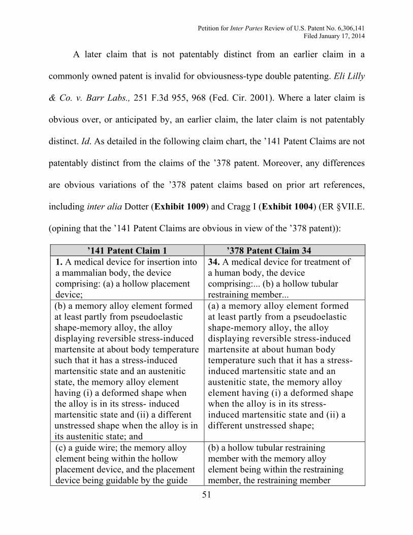
Petition for Inter Partes Review of U.S. Patent No. 6,306,141 Filed January 17, 2014
51
A later claim that is not patentably distinct from an earlier claim in a
commonly owned patent is invalid for obviousness-type double patenting. Eli Lilly
& Co. v. Barr Labs., 251 F.3d 955, 968 (Fed. Cir. 2001). Where a later claim is
obvious over, or anticipated by, an earlier claim, the later claim is not patentably
distinct. Id. As detailed in the following claim chart, the ’141 Patent Claims are not
patentably distinct from the claims of the ’378 patent. Moreover, any differences
are obvious variations of the ’378 patent claims based on prior art references,
including inter alia Dotter (Exhibit 1009) and Cragg I (Exhibit 1004) (ER §VII.E.
(opining that the ’141 Patent Claims are obvious in view of the ’378 patent)):
’141 Patent Claim 1 ’378 Patent Claim 34 1. A medical device for insertion into a mammalian body, the device comprising: (a) a hollow placement device;
34. A medical device for treatment of a human body, the device comprising:... (b) a hollow tubular restraining member...
(b) a memory alloy element formed at least partly from pseudoelastic shape-memory alloy, the alloy displaying reversible stress-induced martensite at about body temperature such that it has a stress-induced martensitic state and an austenitic state, the memory alloy element having (i) a deformed shape when the alloy is in its stress- induced martensitic state and (ii) a different unstressed shape when the alloy is in its austenitic state; and
(a) a memory alloy element formed at least partly from a pseudoelastic shape-memory alloy, the alloy displaying reversible stress-induced martensite at about human body temperature such that it has a stress-induced martensitic state and an austenitic state, the memory alloy element having (i) a deformed shape when the alloy is in its stress-induced martensitic state and (ii) a different unstressed shape;
(c) a guide wire; the memory alloy element being within the hollow placement device, and the placement device being guidable by the guide
(b) a hollow tubular restraining member with the memory alloy element being within the restraining member, the restraining member
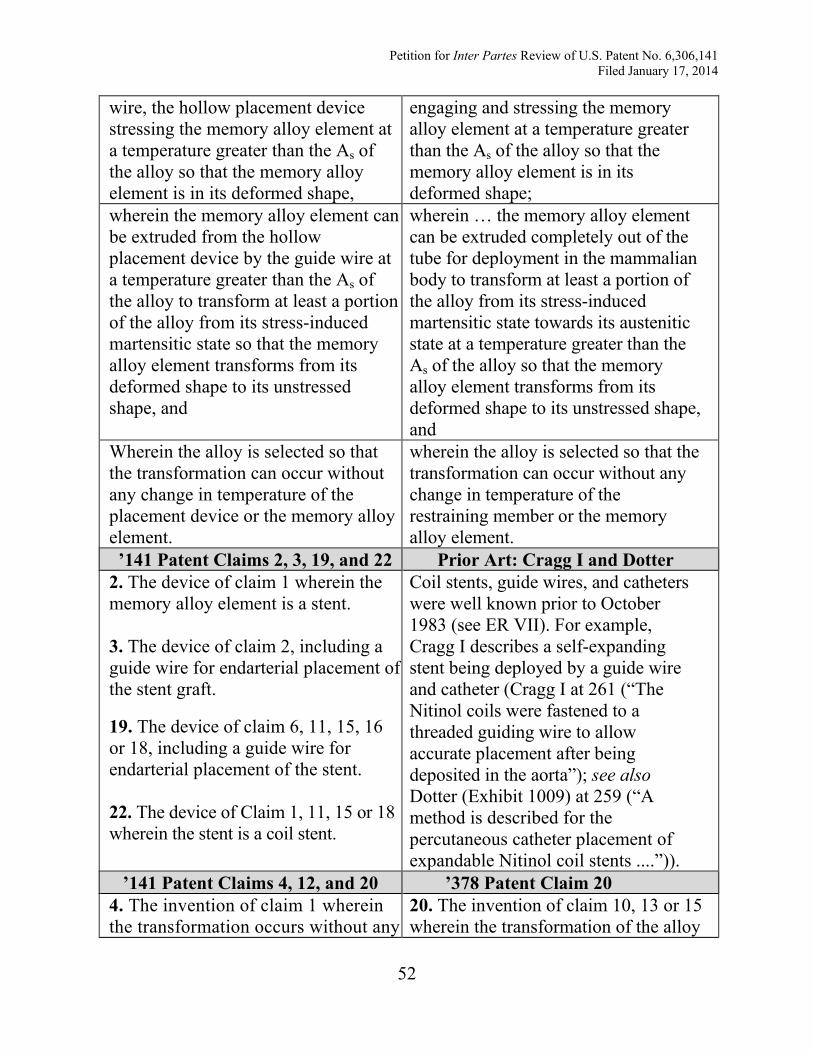
Petition for Inter Partes Review of U.S. Patent No. 6,306,141 Filed January 17, 2014
52
wire, the hollow placement device stressing the memory alloy element at a temperature greater than the As of the alloy so that the memory alloy element is in its deformed shape,
engaging and stressing the memory alloy element at a temperature greater than the As of the alloy so that the memory alloy element is in its deformed shape;
wherein the memory alloy element can be extruded from the hollow placement device by the guide wire at a temperature greater than the As of the alloy to transform at least a portion of the alloy from its stress-induced martensitic state so that the memory alloy element transforms from its deformed shape to its unstressed shape, and
wherein … the memory alloy element can be extruded completely out of the tube for deployment in the mammalian body to transform at least a portion of the alloy from its stress-induced martensitic state towards its austenitic state at a temperature greater than the As of the alloy so that the memory alloy element transforms from its deformed shape to its unstressed shape, and
Wherein the alloy is selected so that the transformation can occur without any change in temperature of the placement device or the memory alloy element.
wherein the alloy is selected so that the transformation can occur without any change in temperature of the restraining member or the memory alloy element.
’141 Patent Claims 2, 3, 19, and 22 Prior Art: Cragg I and Dotter 2. The device of claim 1 wherein the memory alloy element is a stent. 3. The device of claim 2, including a guide wire for endarterial placement of the stent graft.
19. The device of claim 6, 11, 15, 16 or 18, including a guide wire for endarterial placement of the stent. 22. The device of Claim 1, 11, 15 or 18 wherein the stent is a coil stent.
Coil stents, guide wires, and catheters were well known prior to October 1983 (see ER VII). For example, Cragg I describes a self-expanding stent being deployed by a guide wire and catheter (Cragg I at 261 (“The Nitinol coils were fastened to a threaded guiding wire to allow accurate placement after being deposited in the aorta”); see also Dotter (Exhibit 1009) at 259 (“A method is described for the percutaneous catheter placement of expandable Nitinol coil stents ....”)).
’141 Patent Claims 4, 12, and 20 ’378 Patent Claim 20 4. The invention of claim 1 wherein the transformation occurs without any
20. The invention of claim 10, 13 or 15 wherein the transformation of the alloy
Petition for Inter Partes Review of U.S. Patent No. 6,306,141 Filed January 17, 2014
53
change in the state of the placement device. 12. The device of claim 11, wherein the transformation of the alloy occurs without any change in the state of the restraining means.
20. The device of claim 15, 16, or 18, wherein the transformation of the alloy occurs without any change in state of the restraint.
occurs without any change in the state of the restraining member.
‘141 Patent Claims 5, 8, 13, and 21 ’378 Patent Claim 3 5. The device of claim 1, wherein the hollow placement device is a catheter. 8. A device as claimed in claim 6 or 7, in which the restraint is a catheter.
13. The device of claim 11 wherein the restraining means is a catheter.
21. The device of claim 1, 15, 16, or 18, wherein the restraint is a catheter.
3. A device as claimed in claim 2, in which the restraint is a catheter.
‘141 Patent Claim 6 ’378 Patent Claim 1 6. A medical device which comprises: (a) a stent for endarterial placement within a human body so that the stent is substantially at human body temperature, the stent comprising a shape memory alloy which displays stress-induced martensite behavior at body temperature; and
1. A medical device which comprises:
(a) an element for use within a human body or in such proximity to a human body that the device is substantially at human body temperature, the element comprising a shape memory alloy which displays a stress-induced martensite behavior at body temperature; and
(b) a restraint holding the stent in a deformed configuration at a temperature less than the body temperature of the human for
(b) a restraint holding the shape memory alloy element in a deformed configuration at a temperature less than the body
Petition for Inter Partes Review of U.S. Patent No. 6,306,141 Filed January 17, 2014
54
endarterial positioning of the stent within the human body in its deformed configuration, the deformation occurring through the formation of stress-induced martensite;
temperature of the human for positioning the shape memory alloy element within or in proximity to the human body in its deformed configuration, the deformation occurring through the formation of stress-induced martensite;
wherein the stent is sufficiently deformed that when the stent is at human body temperature removal of the restraint from the stent, without change in temperature of the device, releases at least a portion of the stent from its deformed configuration.
wherein the shape memory alloy element is sufficiently deformed that when the shape memory alloy element is at human body temperature removal of the restraint from the shape memory alloy element, without change in temperature of the device, releases at least a portion of the shape memory alloy element from its deformed configuration.
‘141 Patent Claims 7 and 14 ’378 Patent Claim 2 7. A device as claimed in 6, in which the restraint is hollow, and the stent is positioned at least partially within the restraint. 14. The device of claim 13 wherein the stent is within the catheter.
2. A device as claimed in claim 1, in which the restraint is hollow, and the shape memory alloy element is positioned at least partially within the restraint.
‘141 Patent Claim 9 ’378 Patent Claim 7 9. A device as claimed in claim 6 or 7, in which the stent has a transverse dimension and a longitudinal dimension, and wherein the stent is deformed by its transverse dimension being reduced, and wherein the restraint prevents transverse expansion of the stent.
7. A device as claimed in claim 2, in which the shape memory alloy element has a transverse dimension and a longitudinal dimension, and wherein the shape memory alloy element is deformed by its transverse dimension being reduced, and wherein the restraint prevents transverse expansion of the element.
‘141 Patent Claim 10 ’378 Patent Claim 8 10. The device of claim 6, wherein the shape memory alloy element is
8. The device of claim 1, wherein the shape memory alloy element is
Petition for Inter Partes Review of U.S. Patent No. 6,306,141 Filed January 17, 2014
55
sufficiently deformed that removal of the restraint from the shape memory alloy releases at least a portion of the shape alloy element from its deformed configuration without change in state of the restraint.
sufficiently deformed that removal of the restraint from the shape memory alloy releases at least a portion of the shape memory alloy element from its deformed configuration without change in state of the restraint.
‘141 Patent Claim 11 ’378 Patent Claim 10 11. A medical device suitable for placement within a mammalian body for treatment of the mammalian body, the device comprising: (a) a stent formed at least partly from a pseudoelastic shape-memory alloy, the alloy having a reversible stress-induced martensitic state and an austenitic state,
10. A medical device for treatment of a mammalian body, the device comprising: (a) a memory alloy element formed at least partly from a pseudoelastic shape memory alloy, the alloy displaying reversible stress-induced martensite at about body temperature such that it has a stress-induced martensitic state and an austenitic state,
the memory alloy element having (i) a deformed shape when the alloy is in its stress-induced martensitic state and (ii) a different, unstressed shape; and
the memory alloy element having (i) a deformed shape when the alloy is in its stress-induced martensitic shape and (ii) a different unstressed shape; and
(b) restraining means engaging and stressing the stent at a temperature less than the body temperature of the mammal and greater than the As of the alloy for positioning the stent within the mammalian body while the stent is in its deformed shape;
(b) a hollow restraining member with the memory alloy element being within the restraining member, the restraining member engaging and stressing the memory alloy element at a temperature less than the body temperature of the human and greater than the As of the alloy for positioning the memory alloy element within or in proximity to the mammalian body while the memory alloy element is in its deformed shape;
wherein the alloy is selected so that removal of the restraining means from the stent at a temperature greater than the As of the alloy when
wherein the restraining member and the memory alloy element are movable relative to each other to transform at least a portion of the
Petition for Inter Partes Review of U.S. Patent No. 6,306,141 Filed January 17, 2014
56
the device is placed within the mammalian body, transforms at least a portion of the alloy from its stressed-induced martensitic state so that the stent transforms from its deformed relatively straightened shape towards its unstressed relatively coiled shape, without any change in temperature of the restraining means or the stent being required for the transformation of the alloy.
alloy from its stress-induced martensitic state at a temperature greater than the As of the alloy so that the memory alloy element transforms from its deformed shape toward its unstressed shape, and wherein the alloy is selected so that the transformation can occur without any change in temperature of the restraining member or the memory alloy element.
‘141 Patent Claim 15 ’378 Patent Claim 10 15. A medical device for treatment of a mammalian body, the device comprising: (a) a memory alloy stent formed at least partly from a pseudoelastic shape-memory alloy, the alloy displaying reversible stress-induced martensite at about the mammalian body temperature such that it has a stress-induced martensitic state and an austenitic state,
10. A medical device for treatment of a mammalian body, the device comprising: (a) a memory alloy element formed at least partly from a pseudoelastic shape memory alloy, the alloy displaying reversible stress-induced martensite at about body temperature such that it has a stress-induced martensitic state and an austenitic state,
the memory alloy stent having (i) a deformed relatively straightened shape when the alloy is in its stress-induced martensitic state and (ii) a different unstressed relatively coiled shape;
the memory alloy element having (i) a deformed shape when the alloy is in its stress-induced martensitic shape and (ii) a different unstressed shape; and
(b) a hollow restraining member with the memory alloy stent being within the restraining member, the restraining member engaging and stressing the memory alloy stent at a temperature less than the body temperature of the mammal and greater than the As of the alloy for positioning the memory alloy stent
(b) a hollow restraining member with the memory alloy element being within the restraining member, the restraining member engaging and stressing the memory alloy element at a temperature less than the body temperature of the human and greater than the As of the alloy for positioning the memory alloy element within or in
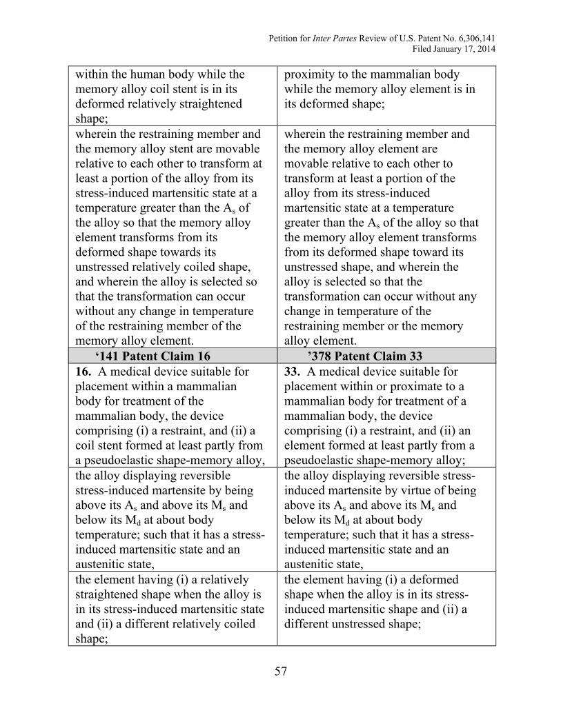
Petition for Inter Partes Review of U.S. Patent No. 6,306,141 Filed January 17, 2014
57
within the human body while the memory alloy coil stent is in its deformed relatively straightened shape;
proximity to the mammalian body while the memory alloy element is in its deformed shape;
wherein the restraining member and the memory alloy stent are movable relative to each other to transform at least a portion of the alloy from its stress-induced martensitic state at a temperature greater than the As of the alloy so that the memory alloy element transforms from its deformed shape towards its unstressed relatively coiled shape, and wherein the alloy is selected so that the transformation can occur without any change in temperature of the restraining member of the memory alloy element.
wherein the restraining member and the memory alloy element are movable relative to each other to transform at least a portion of the alloy from its stress-induced martensitic state at a temperature greater than the As of the alloy so that the memory alloy element transforms from its deformed shape toward its unstressed shape, and wherein the alloy is selected so that the transformation can occur without any change in temperature of the restraining member or the memory alloy element.
‘141 Patent Claim 16 ’378 Patent Claim 33 16. A medical device suitable for placement within a mammalian body for treatment of the mammalian body, the device comprising (i) a restraint, and (ii) a coil stent formed at least partly from a pseudoelastic shape-memory alloy,
33. A medical device suitable for placement within or proximate to a mammalian body for treatment of a mammalian body, the device comprising (i) a restraint, and (ii) an element formed at least partly from a pseudoelastic shape-memory alloy;
the alloy displaying reversible stress-induced martensite by being above its As and above its Ms and below its Md at about body temperature; such that it has a stress-induced martensitic state and an austenitic state,
the alloy displaying reversible stress-induced martensite by virtue of being above its As and above its Ms and below its Md at about body temperature; such that it has a stress-induced martensitic state and an austenitic state,
the element having (i) a relatively straightened shape when the alloy is in its stress-induced martensitic state and (ii) a different relatively coiled shape;
the element having (i) a deformed shape when the alloy is in its stress-induced martensitic shape and (ii) a different unstressed shape;
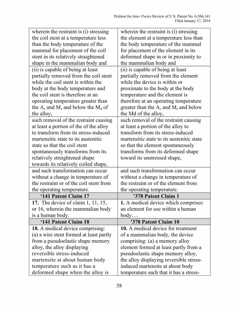
Petition for Inter Partes Review of U.S. Patent No. 6,306,141 Filed January 17, 2014
58
wherein the restraint is (i) stressing the coil stent at a temperature less than the body temperature of the mammal for placement of the coil stent in its relatively straightened shape in the mammalian body and
wherein the restraint is (i) stressing the element at a temperature less than the body temperature of the mammal for placement of the element in its deformed shape in or in proximity to the mammalian body and
(ii) is capable of being at least partially removed from the coil stent while the coil stent is within the body at the body temperature and the coil stent is therefore at an operating temperature greater than the As and Ms and below the Md of the alloy,
(ii) is capable of being at least partially removed from the element while the device is within or proximate to the body at the body temperature and the element is therefore at an operating temperature greater than the As and Ms and below the Md of the alloy,
such removal of the restraint causing at least a portion of the of the alloy to transform from its stress-induced martensitic state to its austenitic state so that the coil stent spontaneously transforms from its relatively straightened shape towards its relatively coiled shape,
such removal of the restraint causing at least a portion of the alloy to transform from its stress-induced martensitic state to its austenitic state so that the element spontaneously transforms from its deformed shape toward its unstressed shape,
and such transformation can occur without a change in temperature of the restraint or of the coil stent from the operating temperature.
and such transformation can occur without a change in temperature of the restraint or of the element from the operating temperature.
‘141 Patent Claim 17 ’378 Patent Claim 1 17. The device of claim 1, 11, 15, or 16, wherein the mammalian body is a human body.
1. A medical device which comprises: an element for use within a human body….
‘141 Patent Claim 18 ’378 Patent Claim 10 18. A medical device comprising: (a) a wire stent formed at least partly from a pseudoelastic shape memory alloy, the alloy displaying reversible stress-induced martensite at about human body temperature such as it has a deformed shape when the alloy is
10. A medical device for treatment of a mammalian body, the device comprising: (a) a memory alloy element formed at least partly from a pseudoelastic shape memory alloy, the alloy displaying reversible stress-induced martensite at about body temperature such that it has a stress-
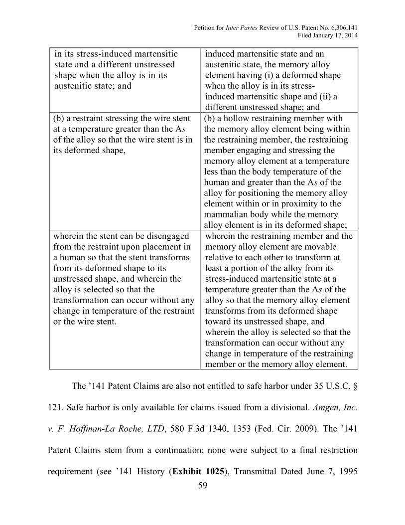
Petition for Inter Partes Review of U.S. Patent No. 6,306,141 Filed January 17, 2014
59
in its stress-induced martensitic state and a different unstressed shape when the alloy is in its austenitic state; and
induced martensitic state and an austenitic state, the memory alloy element having (i) a deformed shape when the alloy is in its stress-induced martensitic shape and (ii) a different unstressed shape; and
(b) a restraint stressing the wire stent at a temperature greater than the As of the alloy so that the wire stent is in its deformed shape,
(b) a hollow restraining member with the memory alloy element being within the restraining member, the restraining member engaging and stressing the memory alloy element at a temperature less than the body temperature of the human and greater than the As of the alloy for positioning the memory alloy element within or in proximity to the mammalian body while the memory alloy element is in its deformed shape;
wherein the stent can be disengaged from the restraint upon placement in a human so that the stent transforms from its deformed shape to its unstressed shape, and wherein the alloy is selected so that the transformation can occur without any change in temperature of the restraint or the wire stent.
wherein the restraining member and the memory alloy element are movable relative to each other to transform at least a portion of the alloy from its stress-induced martensitic state at a temperature greater than the As of the alloy so that the memory alloy element transforms from its deformed shape toward its unstressed shape, and wherein the alloy is selected so that the transformation can occur without any change in temperature of the restraining member or the memory alloy element.
The ’141 Patent Claims are also not entitled to safe harbor under 35 U.S.C. §
121. Safe harbor is only available for claims issued from a divisional. Amgen, Inc.
v. F. Hoffman-La Roche, LTD, 580 F.3d 1340, 1353 (Fed. Cir. 2009). The ’141
Patent Claims stem from a continuation; none were subject to a final restriction
requirement (see ’141 History (Exhibit 1025), Transmittal Dated June 7, 1995