Embed Size (px)
Citation preview
1
In-the-Spectacle-Lens Telescopic Device
Eli Pelia, Fernando Vargas-Martína, b
aSchepens Eye Research Institute, Harvard Medical School,
20 Staniford St., Boston MA 02114; phone: +1 6179122597
fax: +1 6179120112, [email protected].
bDepartamento de Física, Universidad de Murcia, Edificio C, Campus de Espinardo, Murcia,
30100 Spain 30100; phone & fax: +34 968398317, [email protected]
ABSTRACT
Spectacle-mounted telescopic systems are prescribed for individuals with visual impairments.
Bioptic telescopes are typically mounted toward the top of the spectacle lens (or above the
frame) with the telescope eyepiece positioned above the wearer’s pupil. This allows the wearer
to use up and down head tilt movements to quickly alternate between the unmagnified wide view
(through the carrier lens) and the magnified narrow field-of-view (available through the
eyepiece). Rejection of this visual aid has been attributed mainly to its appearance and to the
limited field-of-view through the smaller Galilean designs. We designed a wide-field Keplerian
telescope that is built completely within the spectacle lens. The design uses embedded mirrors
inside the carrier lens for optical pathway folding and conventional lenses or curved mirrors for
magnification power. The short height of the ocular, its position, and a small tilt of the ocular
mirror enable the wearer to simultaneously view the magnified field above the unmagnified view
of the uninterrupted horizontal field. These features improve the cosmetics and utility of the
device. The in-the-lens design will allow the telescope to be mass-produced as a commodity
ophthalmic lens blank that can be surfaced to include the wearer’s spectacle prescription.
Keywords: Visual multiplexing, bioptic telescope, optical visual aid, low vision, macular
degeneration, vision rehabilitation, driving aids.
2
1. Background
Magnification is useful for individuals who suffer from loss of resolution or contrast sensitivity,
due to defects in the optics of the eye or retina. Damage to the fovea (the central part of the
retina) is common in age related macular degeneration (AMD) and many other diseases. This
impairment dramatically affects an individual’s ability to read, recognize faces and perform other
fine discrimination tasks. As the population ages, the number of people affected by this and other
eye diseases causing similar impairments, is expected to grow rapidly.
It is possible to provide sufficient magnification for reading and other tasks performed
within arm’s length using a range of devices, including: high power reading glasses, hand- and
stand-optical magnifiers (using standard lenses, combined standard and binary optics 1), fiber
optics tapers 2, and electronic magnifiers that use a camera and a display 3. A variety of
telescopic devices are used for magnification of distant objects including hand-held, head-
mounted, and spectacle-mounted telescopes in both Galilean and Keplerian designs 4. For
intermediate distances, telescopic devices with manual and electronic auto-focus 5 mechanisms
have been implemented.
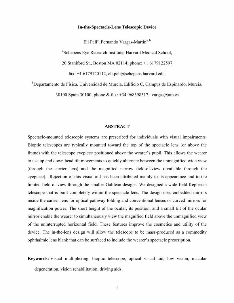
The most successful telescopic devices to assist individuals with low vision (vision
impairment) are bioptic telescopes. Bioptic telescopes are mounted through the spectacle lens
(the carrier lens). The telescope’s eyepiece (ocular lens) is usually positioned above the pupil of
the wearer. The telescope is tilted up by about 10 degrees (Figure 1). This allows the wearer to
look under the telescope eyepiece using their unaided vision through the carrier lens most of the
time. When the wearer notes an object of interest through the carrier lens that is not resolvable, a
slight head tilt can bring the object into view through the telescope providing the needed
magnification. This mode of operation (providing magnification on demand) has been termed
temporal multiplexing 6.
Bioptic telescopes are permitted as driving visual aids for people with low vision in 36
states in the USA 7. When driving (a relatively demanding task), wearers report looking through
the telescope only about 5% of the time 8. In other tasks the telescope may be used even less
frequently.
a b
Figure 1: A monocular Keplerian bioptic telescope. a) Most of the time the
wearer views through the carrier lens without any effect of the telescope. b)
With a slight downward tilt of the head the telescope is brought into the line of
sight enabling a magnified view of the object of interest. The telescope shown
is the 3× Mini focusable Keplerian bioptic manufactured by Ocutech, Inc.
(Chapel Hill, NC)
Through the first part of the 20th century many patents were filed disclosing bioptic
telescopes for the treatment of low vision in the USA and Europe 9-11. However, the devices were
made popular and effective through the efforts of William Feinbloom who was the first to
promote them as a driving aid 12.
Early bioptics were fixed-focus Galilean designs that facilitated small and light weight
devices. The emphasis on small, compact designs resulted in narrow fields of view (FOV; e.g.,
about 9° in a 3× telescope13 14 ) and generally provided relatively dim images. Eventually
Keplerian-based bioptic telescopes were developed that provided brighter images and wider
FOV (e.g., 13º in a 3× telescope13). The Keplerian telescopes were larger and heavier due to the
inherently longer optical path and the need for image-erecting components.
3
4
Although bioptic telescopes can be effectively used in a variety of settings 15, many
visually impaired people reject them 16. The obvious and unsightly appearance of these devices
has been identified as one major reason for the reluctance of people with vision impairments to
use them. Also, the position of the bioptic telescope in the carrier lens causes it to interfere with
eye contact that is crucial for social interactions. Various approaches were taken in attempts to
improve the cosmetic appearance of bioptic telescopes including the use of very small Galilean
telescopes 13, small mostly behind-the-spectacle-lens Keplerian telescopes17, 18, and horizontal
telescopes folded above the spectacle lenses 19. While each of these devices attempts to address
the cosmetic issues hindering the bioptic telescope, they remain obtrusive and many patients who
could benefit from their use continue to reject them. In addition, attempts at miniaturization 20, 21
invariably result in optical compromises including reductions in FOV or image brightness, or
both.
A somewhat less noticeable telescope can be created by combining a high negative power
contact lens 22 or surgically implanted intra-ocular lens (IOL) 23 with a high positive power
spectacle lens. Such telescopes have limited magnification, though 3× is possible. While they
may have a slightly wider FOV than spectacle-mounted telescopes, they severely restrict eye
scanning ability by stabilizing the image on the retina 24, 25. Because the system’s nodal point is
close to the eye’s center of rotation, eye movements do not result in retinal image movements 26.
Therefore, all scanning of the image has to be carried out using head movements. Additionally,
the high power spectacle lens magnifies and distorts the wearer’s eyes and thus interferes with
social eye contact. Patients rejected the cosmetics of the contact lens-spectacle system due to the
unsightly appearance of the high power spectacle lens 27. Furthermore, we believe that the image
stabilization and the full-time field restriction imposed by these systems (when used binocularly,
as they were designed) may also have contributed to the rejection of these devices. A bifocal
intraocular implantable lens (IOL) was developed to be used either with a high power spectacle
lens for magnification, or without it for a non-magnified view 28. Despite reported success in the
5
optical performance of these devices, the large size and poor cosmetics of the doublet spectacle
lens that was used is believed to be the reason for the rejection of such systems by wearers,
despite success in optical performance reported 28. Here too the retinal image stabilization
prevented eye scanning. Using a small high power inset lens in a normal looking carrier lens in
combination with the bifocal IOL 29 might overcome both the cosmetics and image-scanning
limitations of this approach. A fully implanted intra-ocular telescope is now available which
offers normal-looking spectacles and eyes, but requires a surgical procedure 30, 31. The telescope
is implanted in one eye leaving the second eye to provide a wide field of vision for mobility
tasks. In comparison with spectacle-mounted telescopes, the intra-ocular telescope provides
dimmer retinal images, and may interfere with ocular examination and treatment. This miniature
telescope also has a limited FOV, though not as limited as comparable spectacle-mounted
bioptics, and it permits natural eye scanning 25. The implantable devices have a fixed level of
magnification preventing a change in power that may be desirable with progression of the vision
impairment.
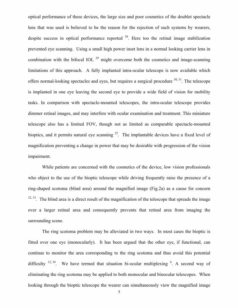
While patients are concerned with the cosmetics of the device, low vision professionals
who object to the use of the bioptic telescope while driving frequently raise the presence of a
ring-shaped scotoma (blind area) around the magnified image (Fig.2a) as a cause for concern
32, 33. The blind area is a direct result of the magnification of the telescope that spreads the image
over a larger retinal area and consequently prevents that retinal area from imaging the
surrounding scene.
The ring scotoma problem may be alleviated in two ways. In most cases the bioptic is
fitted over one eye (monocularly). It has been argued that the other eye, if functional, can
continue to monitor the area corresponding to the ring scotoma and thus avoid this potential
difficulty 12, 34. We have termed that situation bi-ocular multiplexing 6. A second way of
eliminating the ring scotoma may be applied to both monocular and binocular telescopes. When
looking through the bioptic telescope the wearer can simultaneously view the magnified image
of an object together with the unmagnified image of the rest of the scene except for the ring
scotoma (Fig. 2a). With a small FOV, a telescope that is misaligned with the eye’s optical axis
can present a magnified image of an object immediately above the view of the same object
through the carrier lens (Fig. 2b). This method of dealing with the ring scotoma of the bioptic
telescope was termed ‘Simulvision’ and was described with the introduction of the bi-level
telemicroscopic apparatus (BITA) micro Galilean bioptic telescope 35. Simulvision is an
example of spatial multiplexing by shifting 6.
6
a b
Figure 2: A simulated view of a road sign viewed through a 3× telescope. a)
The view through a conventional bioptic. The magnified image on the retina
blocks the view of much of the intersection creating a ring scotoma (blind
area). b) The rectangular field-of-view through the in-the-lens telescope.
The magnified image is shifted up blocking part of the view of the overhead
pedestrian bridge but leaves the intersection in full view. Note the non-
magnified view of the road sign seen under the magnified view. The white
line surrounding the magnified image is only added to make the illustration
clearer.
7
In this manuscript we describe a low vision bioptic telescope that overcomes many of the
limitations of previous designs by building the telescope into the spectacle lens 36. This in-the-
lens design can provide a relatively wide FOV, high magnification, and bright image while also
improving the cosmetics such that the device does not appear too different from other eyewear.
We also show that the new design lends itself to spatial multiplexing by shifting, allowing a wide
(unmagnified) FOV, and to increased light efficiency.
2. Optical Designs
The principal novelty of the in-the-lens telescope is that the optical elements composing a
terrestrial telescope are embedded within the carrier spectacle lens. This requires that the optical
path is folded so that it is mostly orthogonal to the visual axis of the spectacles, and light is
transmitted through the carrier lens body. We describe a series of designs and implementations
below.
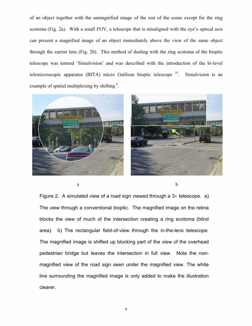
2.1. Periscopic Galilean with laminated lenses
The basic Galilean telescope folded into the lens is shown schematically in Fig.3. A
plane carrier lens of thickness t is shown in a view from above as a rectangle. A positive lens
serving as the objective and a negative lens of higher power serving as the ocular are shown
laminated to the carrier lens. A pair of plane mirrors serves as a periscope to move the image
from the objective to the ocular across the carrier lens.
8
M1 M2
t
c b a
Figure 3: a) A basic schematic design of the in-the-lens telescope with a spectacle
lens of thickness, t, seen from above. For the Galilean design a positive objective
lens and a negative ocular lens are laminated to the carrier lens. Two mirrors serve
to periscopically pass the image from the objective to the ocular. b) An illustration of
the in-the-lens when the wearer looks though the carrier lens. c) The same lens
following a head tilt that brings the telescope in front of the pupil. Note the thin and tall
shape of the telescopic mirrors due to the limitation imposed by the carrier lens
thickness on the width of the mirrors.
The most important design parameter for a bioptic telescope is the magnification. Bioptic
telescopes range in magnification from 1.5× to 8×, with 3× to 4× used most commonly. The
angular magnification M of an afocal Galilean telescope, as shown in Fig. 3, is determined by the
ratio of the object focal length of the objective lens fob (negative in this case) to the image focal
length of the ocular lens f'oc (also negative since the ocular is divergent):
oc
ob
ffM′
= . (1)
In the case of a Galilean telescope M is positive, meaning the final image is erect (not inverted).
The afocal condition is achieved when the distance between objective and ocular lenses,
called tube length L, is equal to the difference of the focal lengths of both lenses. In this
embedded design, light travels through the carrier lens of refractive index n. Under the thin-lens
approximation, it is generally derived as:
( ) ococobocob fMnfnnfffL ′−=′+−=−′= 1 . (2)
Attending to the sign of focal lengths in the case of the Galilean telescope, it results as:
( ) ocfMnL ′−= 1 . (3)
The second most important parameter for a bioptic telescope is the field-of-view (FOV).
Either the objective or the ocular may serve as the limiting aperture in a Galilean telescope. The
FOV, on the retina of the wearer, is determined by either the angle spanned at the pupil by the
ocular lens or the angle spanned by the image of the objective as seen through the ocular; the
smaller of these two angles is the FOV. In the design of the Galilean telescope shown in Fig. 3a,
the carrier lens thickness limits the periscopic mirrors’ width but not their height. Since we
would like to keep the carrier lens as thin as practical for cosmetic and weight considerations,
the field of such a telescope is likely to be taller than it is wide (Fig. 3b). This is less than
optimal as the width of the FOV is considered more important for bioptics than the height. In
addition, the exit pupil, the image of the objective formed by the ocular, is smaller than the
objective itself, since the lateral magnification is 1/M.
The second factor affecting the FOV is the distance between the field-limiting aperture
and the eye’s pupil. Since the device is meant to be embedded in a spectacle lens, the distance
from the last optical surface to the eye should be as similar as possible to that of conventional
spectacle ophthalmic lenses. This vertex distance is usually 12 to 14mm 37. In the case of the
Galilean design the exit pupil of the telescope lies within the telescope. Generally, the exit pupil
acts as a field-limiting aperture and, since the eye can never be placed in the same plane, it limits
9
the FOV and also causes vignetting by reducing the light reaching the pupil from eccentric
objects.
2.2. Keplerian design with laminated lenses
A Keplerian configuration for a bioptic telescope has a number of advantages over the
Galilean design, as described below. The main disadvantages of a Keplerian bioptic telescope are
the larger dimension of the device (for the same magnification and objective lens power) and the
need for an optical erecting element that adds weight and other complications. However, both
limitations are easily overcome with the proposed in-the-lens design. Fig. 4 shows side and front
view schematic illustrations of a Keplerian in-the-lens telescope. The spectacle carrier lens
(dotted line rectangle) has a thickness t. The ocular and objective lenses are laminated to the
carrier lens surfaces. Arrows show the direction light travels across the 4 embedded erecting
mirrors arranged in a configuration similar to the reflections obtained in Abbé's version of the
Porro prisms 38 (also called 2nd kind Porro prisms). Following a head tilt to align the telescope
with the eye, the ocular and M4 are placed in front of the wearer’s eye (as shown in Fig 4b). At
other times the wearer can view through the carrier lens, under mirror M4, benefiting from an
unimpeded FOV.
The same computations (Eq. 1 and 2) apply to a Keplerian telescope with the only
difference being the sign of the ocular focal length (positive), resulting in the tube length being
equal to the sum of the focal lengths of both lenses
( ) ococob fMnffL ′+=−′= 1 . (4)
Thus, a longer optical path is required for a Keplerian design. This additional length is
not difficult to achieve as the Keplerian design needs erecting mirrors which naturally increases
the optical path through the carrier lens.
The orientation of the objective and ocular mirrors (M1 and M2) in the Keplerian design
is such that their height is limited by the carrier lens thickness but not their width (horizontal
10
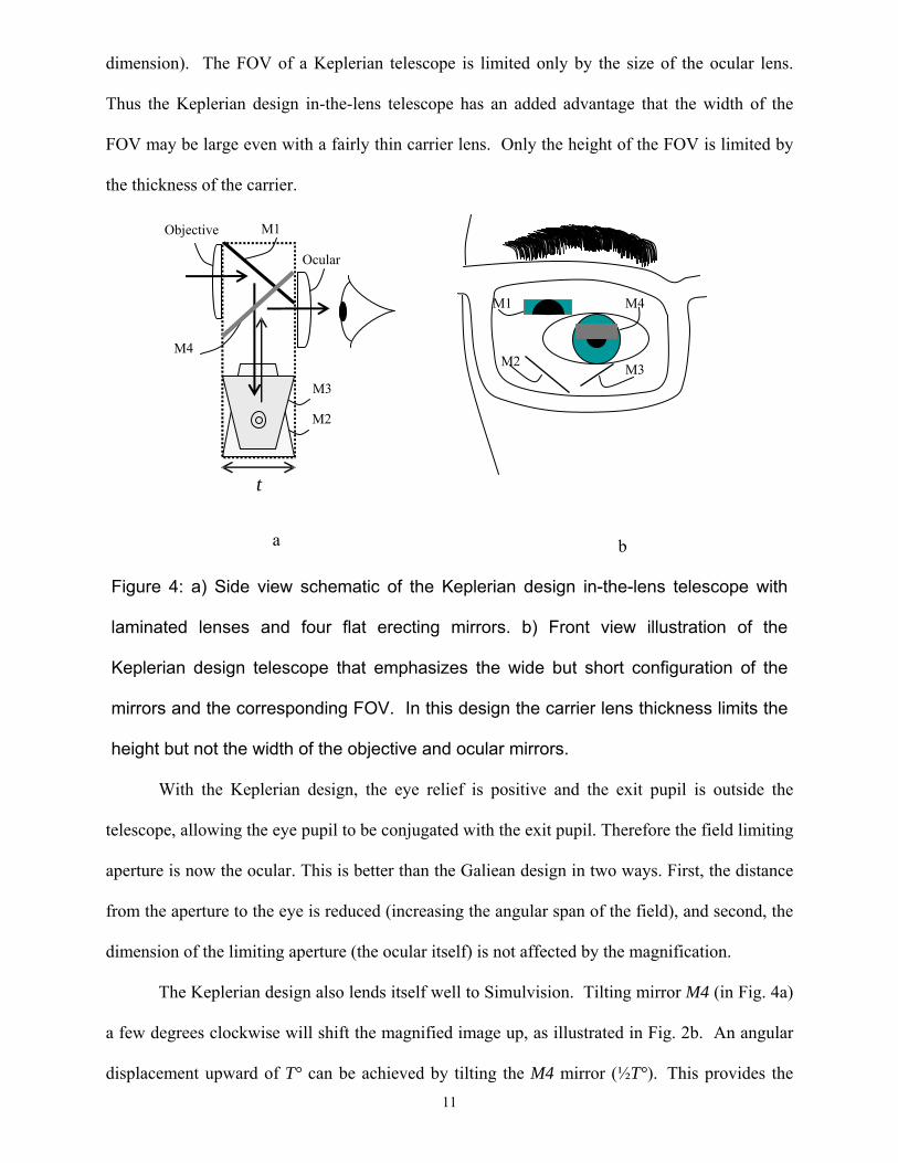
dimension). The FOV of a Keplerian telescope is limited only by the size of the ocular lens.
Thus the Keplerian design in-the-lens telescope has an added advantage that the width of the
FOV may be large even with a fairly thin carrier lens. Only the height of the FOV is limited by
the thickness of the carrier.
11
a
M1
M2 M3
M4
M1
M4
M3
M2
t
Objective
Ocular
b
Figure 4: a) Side view schematic of the Keplerian design in-the-lens telescope with
laminated lenses and four flat erecting mirrors. b) Front view illustration of the
Keplerian design telescope that emphasizes the wide but short configuration of the
mirrors and the corresponding FOV. In this design the carrier lens thickness limits the
height but not the width of the objective and ocular mirrors.
With the Keplerian design, the eye relief is positive and the exit pupil is outside the
telescope, allowing the eye pupil to be conjugated with the exit pupil. Therefore the field limiting
aperture is now the ocular. This is better than the Galiean design in two ways. First, the distance
from the aperture to the eye is reduced (increasing the angular span of the field), and second, the
dimension of the limiting aperture (the ocular itself) is not affected by the magnification.
The Keplerian design also lends itself well to Simulvision. Tilting mirror M4 (in Fig. 4a)
a few degrees clockwise will shift the magnified image up, as illustrated in Fig. 2b. An angular
displacement upward of T° can be achieved by tilting the M4 mirror (½T°). This provides the
12
wearer an unobstructed, non-magnified view of the environment through the carrier lens at the
same time as a magnified image (through the telescope) that is translated vertically, enabling an
open, wide horizontal FOV including that of objects seen through the telescope. The magnified
image could be shifted in other directions, but shifting the magnified image above the
unmagnified view is preferable because the magnified image occupies an area of the visual field
that is less likely to include obstacles or other mobility relevant objects. The in-the-lens telescope
design facilitates Simulvision, in part, because there is no opaque frame or mounting structure to
block the unmagnified view.
The optical elements that act as objective and ocular lenses can be conventional meniscus
lenses attached to the carrier lens as shown in Figs. 3 and 4. However, those lenses could be
replaced with curved mirrors, Fresnel lenses, diffractive lenses, or holographic elements. These
other elements have a durability advantage as they can be embedded within the carrier lens.
Curved mirrors also offer several other important benefits: mirrors are free of chromatic
aberration; they yield more optical power with the same curvature when compared with plano-
convex lenses (thus reducing the dimension requirements for the carrier lens); and the distance
between mirrors needed to create an afocal optical system does not depend on the refractive
index of the carrier lens, but only on their focal lengths.
2.3. Keplerian prototype with laminated lenses
In a first prototype we implemented the generic design described in section 2.2 (shown in
Fig. 4). The lower image erecting mirrors were made by cutting an ophthalmic lens blank and
the periscopic mirrors were created using small prisms. All mirroring was achieved in this design
through total internal reflection, as shown in Fig. 5.
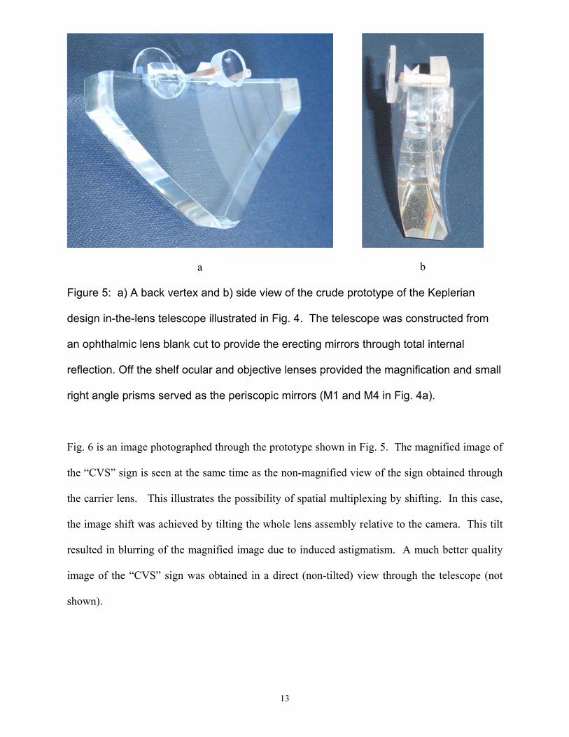
b a
Figure 5: a) A back vertex and b) side view of the crude prototype of the Keplerian
design in-the-lens telescope illustrated in Fig. 4. The telescope was constructed from
an ophthalmic lens blank cut to provide the erecting mirrors through total internal
reflection. Off the shelf ocular and objective lenses provided the magnification and small
right angle prisms served as the periscopic mirrors (M1 and M4 in Fig. 4a).
Fig. 6 is an image photographed through the prototype shown in Fig. 5. The magnified image of
the “CVS” sign is seen at the same time as the non-magnified view of the sign obtained through
the carrier lens. This illustrates the possibility of spatial multiplexing by shifting. In this case,
the image shift was achieved by tilting the whole lens assembly relative to the camera. This tilt
resulted in blurring of the magnified image due to induced astigmatism. A much better quality
image of the “CVS” sign was obtained in a direct (non-tilted) view through the telescope (not
shown).
13
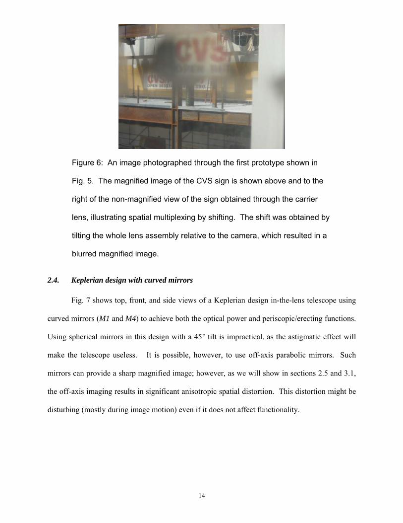
Figure 6: An image photographed through the first prototype shown in
Fig. 5. The magnified image of the CVS sign is shown above and to the
right of the non-magnified view of the sign obtained through the carrier
lens, illustrating spatial multiplexing by shifting. The shift was obtained by
tilting the whole lens assembly relative to the camera, which resulted in a
blurred magnified image.
2.4. Keplerian design with curved mirrors
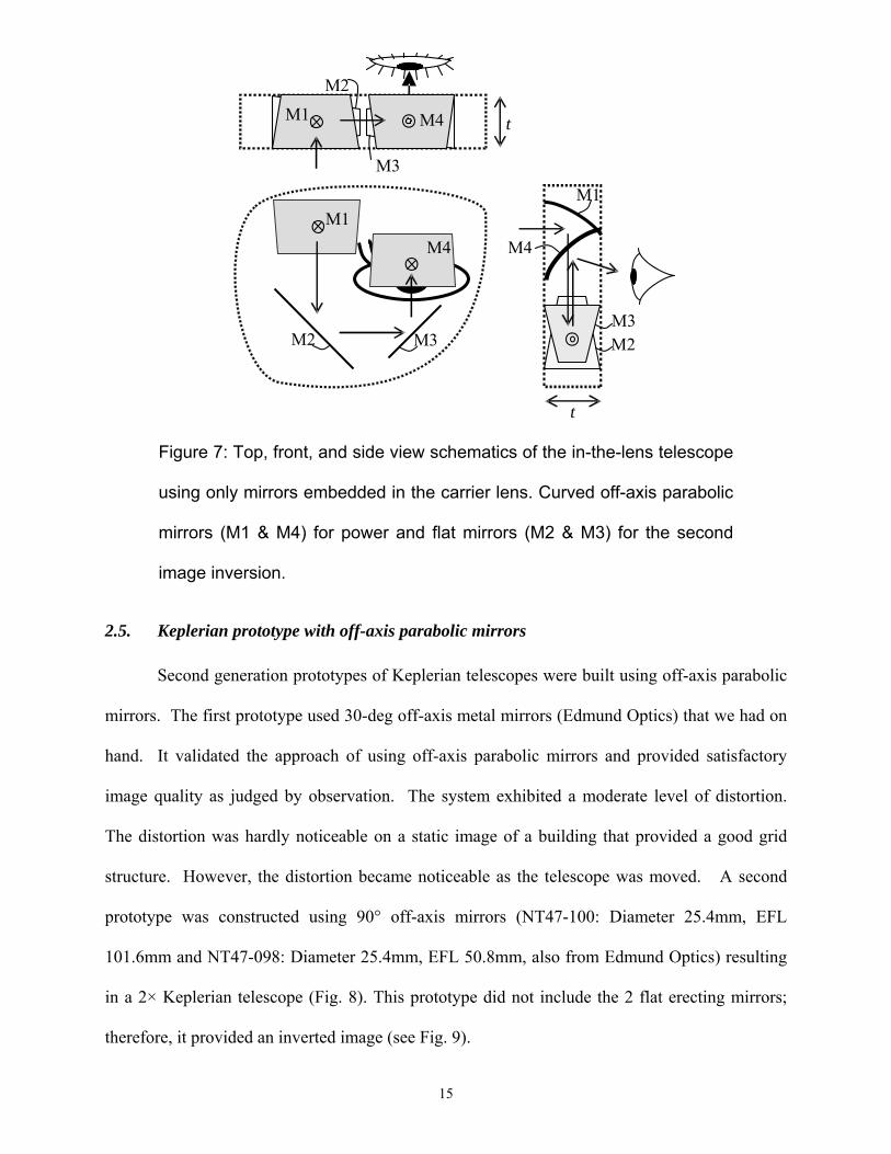
Fig. 7 shows top, front, and side views of a Keplerian design in-the-lens telescope using
curved mirrors (M1 and M4) to achieve both the optical power and periscopic/erecting functions.
Using spherical mirrors in this design with a 45° tilt is impractical, as the astigmatic effect will
make the telescope useless. It is possible, however, to use off-axis parabolic mirrors. Such
mirrors can provide a sharp magnified image; however, as we will show in sections 2.5 and 3.1,
the off-axis imaging results in significant anisotropic spatial distortion. This distortion might be
disturbing (mostly during image motion) even if it does not affect functionality.
14
M1
M4
M3 M2 M2 M3
M1
M4M1
M2
M3
t
M4
t
Figure 7: Top, front, and side view schematics of the in-the-lens telescope
using only mirrors embedded in the carrier lens. Curved off-axis parabolic
mirrors (M1 & M4) for power and flat mirrors (M2 & M3) for the second
image inversion.
2.5. Keplerian prototype with off-axis parabolic mirrors
Second generation prototypes of Keplerian telescopes were built using off-axis parabolic
mirrors. The first prototype used 30-deg off-axis metal mirrors (Edmund Optics) that we had on
hand. It validated the approach of using off-axis parabolic mirrors and provided satisfactory
image quality as judged by observation. The system exhibited a moderate level of distortion.
The distortion was hardly noticeable on a static image of a building that provided a good grid
structure. However, the distortion became noticeable as the telescope was moved. A second
prototype was constructed using 90° off-axis mirrors (NT47-100: Diameter 25.4mm, EFL
101.6mm and NT47-098: Diameter 25.4mm, EFL 50.8mm, also from Edmund Optics) resulting
in a 2× Keplerian telescope (Fig. 8). This prototype did not include the 2 flat erecting mirrors;
therefore, it provided an inverted image (see Fig. 9).
15
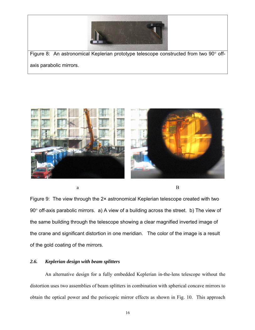
Figure 8: An astronomical Keplerian prototype telescope constructed from two 90° off-
axis parabolic mirrors.
a B
Figure 9: The view through the 2× astronomical Keplerian telescope created with two
90° off-axis parabolic mirrors. a) A view of a building across the street. b) The view of
the same building through the telescope showing a clear magnified inverted image of
the crane and significant distortion in one meridian. The color of the image is a result
of the gold coating of the mirrors.
2.6. Keplerian design with beam splitters
An alternative design for a fully embedded Keplerian in-the-lens telescope without the
distortion uses two assemblies of beam splitters in combination with spherical concave mirrors to
obtain the optical power and the periscopic mirror effects as shown in Fig. 10. This approach
16
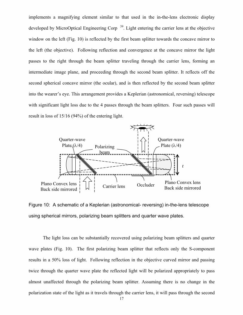
implements a magnifying element similar to that used in the in-the-lens electronic display
developed by MicroOptical Engineering Corp 39. Light entering the carrier lens at the objective
window on the left (Fig. 10) is reflected by the first beam splitter towards the concave mirror to
the left (the objective). Following reflection and convergence at the concave mirror the light
passes to the right through the beam splitter traveling through the carrier lens, forming an
intermediate image plane, and proceeding through the second beam splitter. It reflects off the
second spherical concave mirror (the ocular), and is then reflected by the second beam splitter
into the wearer’s eye. This arrangement provides a Keplerian (astronomical, reversing) telescope
with significant light loss due to the 4 passes through the beam splitters. Four such passes will
result in loss of 15/16 (94%) of the entering light.
Plano Convex lens Back side mirrored
Quarter-wave Plate (λ/4) Polarizing
beam
Carrier lens
Quarter-wave Plate (λ/4)
Plano Convex lens Back side mirrored
Occluder
t
Figure 10: A schematic of a Keplerian (astronomical- reversing) in-the-lens telescope
using spherical mirrors, polarizing beam splitters and quarter wave plates.
The light loss can be substantially recovered using polarizing beam splitters and quarter
wave plates (Fig. 10). The first polarizing beam splitter that reflects only the S-component
results in a 50% loss of light. Following reflection in the objective curved mirror and passing
twice through the quarter wave plate the reflected light will be polarized appropriately to pass
almost unaffected through the polarizing beam splitter. Assuming there is no change in the
polarization state of the light as it travels through the carrier lens, it will pass through the second 17
18
polarizing beam splitter with minimal loss. Because of two passes through the quarter wave
plate associated with the second mirror, the light will then be reflected at the second beam
splitter. Thus the total light loss can be limited to 50% in an ideal situation. In practice, both
reflection and transmission factors can be only about 80% efficient for the selected polarization
state. After two reflections and two transmissions through the beam splitters, a total loss of light
would be about 80% from natural light (0.5 × 0.8 4). Because the eye’s sensitivity is logarithmic,
80% loss of brightness should not significantly impact the functionality of the telescope. The
light loss can be compensated for, in part, by increasing the width of the objective lens providing
more light collection, as discussed below.
An additional advantage of the beam splitter design is that the semitransparent beam
splitter is less visible than a regular mirror, which improves the cosmetic appearance of the
device. However, this advantage holds only for the objective; the ocular beam splitter requires
an opaque backing to improve the contrast of the image for the wearer. The reduced visibility of
the objective means that it can be made larger and brought closer to the ocular, as it will not
block the view through the carrier lens. Using a semi-transparent mirror also removes the
constraint that the objective mirror be placed farther from the line of sight of the wearer, thus
allowing the carrier lens to be made smaller. A smaller carrier lens reduces system weight, and is
also currently more fashionable. The ability to see through the objective area also allows for a
wider objective, which can in part compensate for the light loss at the first beam splitter.
The opaque occluder for the ocular beam splitter can be achieved by providing a polarizer
across the whole front of the lens. The polarizer will turn opaque for the ocular lens but will
remain transparent for the objective lens. The light attenuation through the polarizer across the
whole carrier lens may provide a glare control which will increase both the visual comfort of the
wearer and the relative brightness of the view through the telescope (as compared to the view
through the carrier lens).
19
A challenge to the beam-splitter based approach, however, is that any birefringence in the
carrier lens material can rotate the polarization of the light. The rotated light will then be
partially reflected, rather than transmitted, in the first pass through the second beam splitter and
will reduce the light efficiency of the system. Thus the carrier lens has to be as free as possible
from birefringence effects.
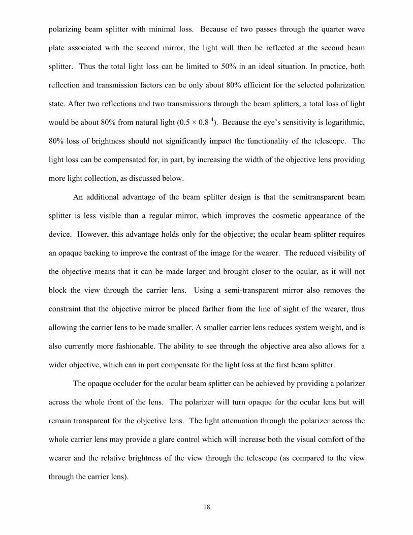
To convert the astronomical Keplerian telescope design using beam splitters (Fig. 10) to a
terrestrial setup requires an erecting system. Fig. 11 illustrates one such terrestrial design
constructed by rotating the two assemblies around axes perpendicular to the carrier lens
ultimately placing the spherical mirrors above the beam splitters. This design, similar to the
basic Keplerian design (Fig. 4), uses the beam splitters as part of the image erecting system.
Importantly, this design preserves the property that the width of the fields and the size of the
objective are not limited by the thickness of the carrier lens.
M3 M2
M2 M3
d
λ/4 M4
BS2 λ/4
M4
BSOccluder
λ/4 BS1
M1
λ/4
BS1
M1
Figure 11: Front and side views of the Keplerian (terrestrial-erecting) in-the-lens
telescope design using polarizing beam splitters and spherical mirrors. Quarter
wave plates (λ/4) are inserted between the beam splitters and the mirrors. Half of
the light is lost at the first reflection in the beam splitter but ideally the quarter wave
plate assures that the light reflected from the mirror is polarized to pass unaffected
through the beam splitter. This light polarization causes no light to be lost through
both passes in the second beam splitter. The occluder in front of the ocular beam
splitter is required to block the see-through view and increase the contrast of the
magnified image. The ocular and objective are shown at different vertical positions
on the carrier only to facilitate the side view illustration; they can be placed at the
same height if needed.
2.7. Keplerian prototype with polarizing beam splitters
The third prototype implemented the totally embedded design with polarizing beam splitters
(Fig. 12). It included as objective elements the magnifier from the MicroOptical see-through
head-mounted display EyeGlass (after removing the display) 39. This element included a
broadband polarizing beam splitter, a quarter wave plate (centered in the visible spectrum) and
the spherical mirror. All the elements were embedded in an 8mm thick carrier lens. For the
20
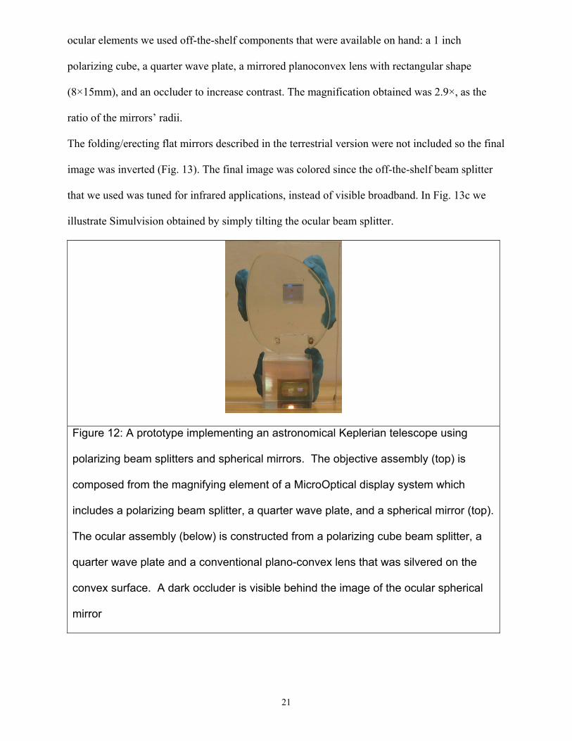
ocular elements we used off-the-shelf components that were available on hand: a 1 inch
polarizing cube, a quarter wave plate, a mirrored planoconvex lens with rectangular shape
(8×15mm), and an occluder to increase contrast. The magnification obtained was 2.9×, as the
ratio of the mirrors’ radii.
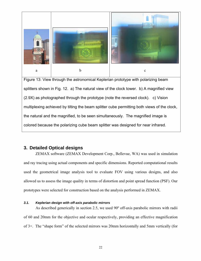
The folding/erecting flat mirrors described in the terrestrial version were not included so the final
image was inverted (Fig. 13). The final image was colored since the off-the-shelf beam splitter
that we used was tuned for infrared applications, instead of visible broadband. In Fig. 13c we
illustrate Simulvision obtained by simply tilting the ocular beam splitter.
21
Figure 12: A prototype implementing an astronomical Keplerian telescope using
polarizing beam splitters and spherical mirrors. The objective assembly (top) is
composed from the magnifying element of a MicroOptical display system which
includes a polarizing beam splitter, a quarter wave plate, and a spherical mirror (top).
The ocular assembly (below) is constructed from a polarizing cube beam splitter, a
quarter wave plate and a conventional plano-convex lens that was silvered on the
convex surface. A dark occluder is visible behind the image of the ocular spherical
mirror
c
a b
Figure 13: View through the astronomical Keplerian prototype with polarizing beam
splitters shown in Fig. 12. a) The natural view of the clock tower. b) A magnified view
(2.9X) as photographed through the prototype (note the reversed clock). c) Vision
multiplexing achieved by tilting the beam splitter cube permitting both views of the clock,
the natural and the magnified, to be seen simultaneously. The magnified image is
colored because the polarizing cube beam splitter was designed for near infrared.
3. Detailed Optical designs ZEMAX software (ZEMAX Development Corp., Bellevue, WA) was used in simulation
and ray tracing using actual components and specific dimensions. Reported computational results
used the geometrical image analysis tool to evaluate FOV using various designs, and also
allowed us to assess the image quality in terms of distortion and point spread function (PSF). Our
prototypes were selected for construction based on the analysis performed in ZEMAX.
3.1. Keplerian design with off-axis parabolic mirrors As described generically in section 2.5, we used 90º off-axis parabolic mirrors with radii
of 60 and 20mm for the objective and ocular respectively, providing an effective magnification
of 3×. The “shape form” of the selected mirrors was 20mm horizontally and 5mm vertically (for
22
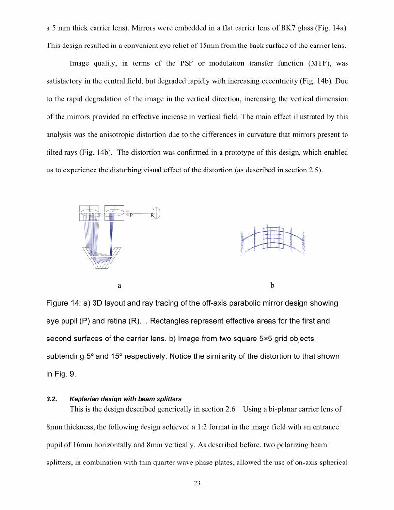
a 5 mm thick carrier lens). Mirrors were embedded in a flat carrier lens of BK7 glass (Fig. 14a).
This design resulted in a convenient eye relief of 15mm from the back surface of the carrier lens.
Image quality, in terms of the PSF or modulation transfer function (MTF), was
satisfactory in the central field, but degraded rapidly with increasing eccentricity (Fig. 14b). Due
to the rapid degradation of the image in the vertical direction, increasing the vertical dimension
of the mirrors provided no effective increase in vertical field. The main effect illustrated by this
analysis was the anisotropic distortion due to the differences in curvature that mirrors present to
tilted rays (Fig. 14b). The distortion was confirmed in a prototype of this design, which enabled
us to experience the disturbing visual effect of the distortion (as described in section 2.5).
R P
a b
Figure 14: a) 3D layout and ray tracing of the off-axis parabolic mirror design showing
eye pupil (P) and retina (R). . Rectangles represent effective areas for the first and
second surfaces of the carrier lens. b) Image from two square 5×5 grid objects,
subtending 5º and 15º respectively. Notice the similarity of the distortion to that shown
in Fig. 9.
3.2. Keplerian design with beam splitters This is the design described generically in section 2.6. Using a bi-planar carrier lens of
8mm thickness, the following design achieved a 1:2 format in the image field with an entrance
pupil of 16mm horizontally and 8mm vertically. As described before, two polarizing beam
splitters, in combination with thin quarter wave phase plates, allowed the use of on-axis spherical
23
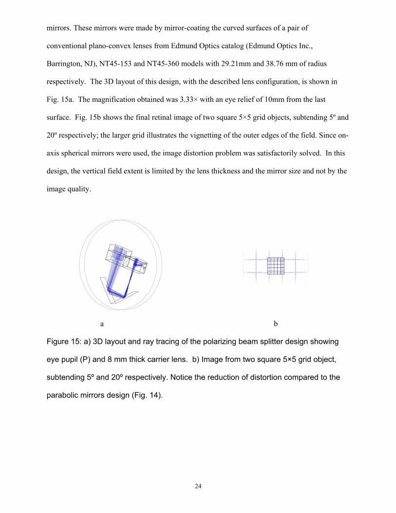
mirrors. These mirrors were made by mirror-coating the curved surfaces of a pair of
conventional plano-convex lenses from Edmund Optics catalog (Edmund Optics Inc.,
Barrington, NJ), NT45-153 and NT45-360 models with 29.21mm and 38.76 mm of radius
respectively. The 3D layout of this design, with the described lens configuration, is shown in
Fig. 15a. The magnification obtained was 3.33× with an eye relief of 10mm from the last
surface. Fig. 15b shows the final retinal image of two square 5×5 grid objects, subtending 5º and
20º respectively; the larger grid illustrates the vignetting of the outer edges of the field. Since on-
axis spherical mirrors were used, the image distortion problem was satisfactorily solved. In this
design, the vertical field extent is limited by the lens thickness and the mirror size and not by the
image quality.
24
P
b a
Figure 15: a) 3D layout and ray tracing of the polarizing beam splitter design showing
eye pupil (P) and 8 mm thick carrier lens. b) Image from two square 5×5 grid object,
subtending 5º and 20º respectively. Notice the reduction of distortion compared to the
parabolic mirrors design (Fig. 14).
25
4. Additional considerations
4.1. Field-of-view
The ocular lens (mirror) of the in-the-lens telescope is likely to be rectangular in shape. In
the horizontal dimension, the only limitations on the lens size are: the dimension of the lens
itself, the spectacle frame, and the value chosen for the telescope length, L. The vertical extent of
the lenses, however, is limited by the carrier lens thickness t. The embedded ocular mirror (M4 in
Fig. 7) would be the field stop, and we can approximate the restriction to its vertical size as being
less than or equal to t. A reasonable range of carrier lens thickness would be 5 to 10mm. For
example, a thickness of 10mm with a 10mm eye relief allows a vertical visual field up to 53° in
the image space (on the retina), which translates to approximately 18° in object space, 50%
wider than most current bioptic telescopes. The horizontal FOV (which is less restricted) may be
as much as twice as wide as the vertical dimension. The horizontal extent of the FOV is usually
considered more important for navigation and reading, so even thinner carrier lenses would be
acceptable.
4.2. Light economy
The dimensions chosen for the carrier lens (e.g. thickness) limit the dimensions of the
objective lens (mirror), which in turn also determine the size of the exit pupil. The exit pupil size
is important in determining the light efficiency of the telescope. When the exit pupil completely
covers the eye’s pupil the light efficiency is maximal at 100%. As stated above, the carrier lens
thickness limits the vertical extent of the objective and thus, the exit pupil. However, the
horizontal extent can be much larger and is not constrained by the thickness, resulting in a wide
rectangular shaped objective. The exit pupil, the image of the objective aperture through the
ocular, will also have the dimensions of the objective divided by the magnification. For
example, an entrance pupil of 16×8mm (carrier lens 8mm thick), with a magnification of 3.3×,
yields an exit pupil of 4.8×2.4mm. These dimensions may limit the amount of light entering the
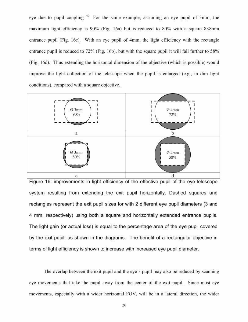
eye due to pupil coupling 40. For the same example, assuming an eye pupil of 3mm, the
maximum light efficiency is 90% (Fig. 16a) but is reduced to 80% with a square 8×8mm
entrance pupil (Fig. 16c). With an eye pupil of 4mm, the light efficiency with the rectangle
entrance pupil is reduced to 72% (Fig. 16b), but with the square pupil it will fall further to 58%
(Fig. 16d). Thus extending the horizontal dimension of the objective (which is possible) would
improve the light collection of the telescope when the pupil is enlarged (e.g., in dim light
conditions), compared with a square objective.
26
Ø 4mm
72%
Ø 3mm 90%
a b
c d
Ø 4mm
58%
Ø 3mm
80%
Figure 16: improvements in light efficiency of the effective pupil of the eye-telescope
system resulting from extending the exit pupil horizontally. Dashed squares and
rectangles represent the exit pupil sizes for with 2 different eye pupil diameters (3 and
4 mm, respectively) using both a square and horizontally extended entrance pupils.
The light gain (or actual loss) is equal to the percentage area of the eye pupil covered
by the exit pupil, as shown in the diagrams. The benefit of a rectangular objective in
terms of light efficiency is shown to increase with increased eye pupil diameter.
The overlap between the exit pupil and the eye’s pupil may also be reduced by scanning
eye movements that take the pupil away from the center of the exit pupil. Since most eye
movements, especially with a wider horizontal FOV, will be in a lateral direction, the wider
horizontal extent of the exit pupil will protect the light efficiency during such eye scanning.
Thus a wider objective is desirable, even if the wider FOV is not necessary.
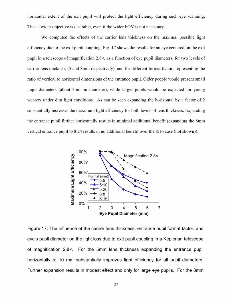
We computed the effects of the carrier lens thickness on the maximal possible light
efficiency due to the exit pupil coupling. Fig. 17 shows the results for an eye centered on the exit
pupil in a telescope of magnification 2.8×, as a function of eye pupil diameters, for two levels of
carrier lens thickness (5 and 8mm respectively), and for different format factors representing the
ratio of vertical to horizontal dimensions of the entrance pupil. Older people would present small
pupil diameters (about 3mm in diameter), while larger pupils would be expected for young
wearers under dim light conditions. As can be seen expanding the horizontal by a factor of 2
substantially increases the maximum light efficiency for both levels of lens thickness. Expanding
the entrance pupil further horizontally results in minimal additional benefit (expanding the 8mm
vertical entrance pupil to 8:24 results in no additional benefit over the 8:16 case (not shown)).
Magnification 2.8×
0%
20%
40%
60%
80%
100%
1 2 3 4 5 6 7Eye Pupil Diameter (mm)
Max
imum
Lig
ht E
ffici
ency
5:55:105:208:88:16
Format (mm)
Figure 17: The influence of the carrier lens thickness, entrance pupil format factor, and
eye’s pupil diameter on the light loss due to exit pupil coupling in a Keplerian telescope
of magnification 2.8×. For the 5mm lens thickness expanding the entrance pupil
horizontally to 10 mm substantially improves light efficiency for all pupil diameters.
Further expansion results in modest effect and only for large eye pupils. For the 8mm
27
28
lens doubling the horizontal dimension is beneficial for all sub optimal pupil sizes but
further increase of horizontal dimension is of little value (not shown)
4.3. Refractive Correction
As eyewear, the in-the-lens telescope must provide refractive correction for the wearer
both through the telescope and through the carrier lens. All our diagrams have illustrated the
carrier lens as a flat lens on both sides and thus could be used only by individuals without any
refractive error (emmetropes). A refractive correcting lens could be laminated to the back
surface of the lens or be ground into that surface. Such a correction will apply equally to the
telescope and the carrier. A standard ophthalmic lens blank is usually provided as a meniscus
lens with a front convex surface (base curve). The positive front base curve is needed for better
cosmetics and for improved optical performance 41. The refractive correction is typically applied
using widely available equipment to grind the back surface of the semi-finished lens blank. The
same approach can be easily applied to the in-the-lens telescope. The lens blank for this
telescope may be developed with a fairly flat base curve. The telescope optical tube length needs
to be slightly modified from the afocal configuration to result in a vergence at the second beam
splitter which is identical to that created by the base curve at the back surface. With such a
blank, the back surface may be ground to the wearer’s prescription on the back surface using
standard ophthalmic lab techniques and equipment. The correction applied to the carrier lens
will result in an appropriate correction for the telescope as well. This would make such a lens
easily dispensable in every ophthalmic shop. Tilts generated in the objective and the ocular due
to the prismatic effect of the carrier lens (Percival’s Rule) can be compensated by centering the
curved surfaces on each beam splitter, if needed. Alternately, the prismatic effect may be used to
support vision multiplexing.
29
A side effect of using a curved carrier lens is that the magnification is slightly reduced
compared with the plano-parallel carrier lens equivalent, using the same curved mirrors. The
reason for such an effect can be easily described as an increase of the objective lens power and a
reduction of the ocular power due to the curved carrier surfaces. Thus, the magnification as the
ratio of both refractive powers is reduced. To quantify the effect, we simulated the same model
described in Fig. 15 embedded in three plano carrier lenses with base curve surfaces of 0, +1, and
+3 diopters, resulting in angular magnifications of 3.3×, 3.2×, and 3.0×, respectively.
5. Discussion
We have described a novel design for bioptic telescopes. We have proposed and tested a
family of possible designs for Galilean and Keplerian bioptic telescopes using either laminated
lenses, embedded curved mirrors, or polarizing converging beam splitters. We have analyzed
these designs through computer simulations and prototyped the designs to demonstrate the
feasibility of such devices. These analyses provide insight into constraints on magnification,
image quality, FOV, distortion, and their utility in vision multiplexing.
Bioptic telescopes are the most efficient visual aid available for distance vision, yet they
are commonly rejected by people with low vision due to their appearance. Our approach
addresses this limitation while maintaining visual performance similar to or better than current
bioptic telescopes. Although the in-the-lens telescope is not cosmetically invisible, its
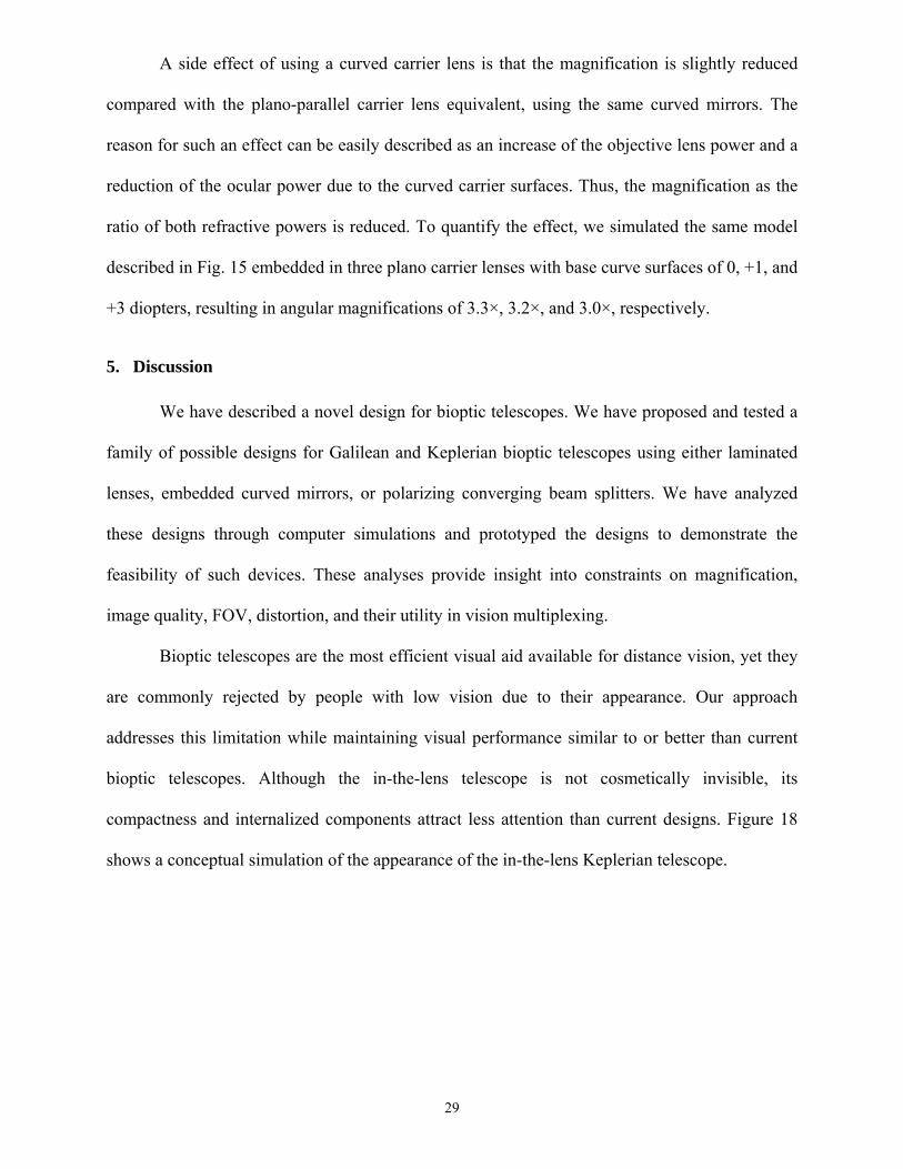
compactness and internalized components attract less attention than current designs. Figure 18
shows a conceptual simulation of the appearance of the in-the-lens Keplerian telescope.
Figure 18: Simulation of the expected
appearance of the in-the-lens telescope.
The proposed in-the-lens telescope can be used to simultaneously view the magnified
image and the unmagnified image of the same area. This vision multiplexing feature improves
wearer orientation and navigation. The wearer can easily locate an object or determine the
relative position of the object. The spectacle lens can include the wearer’s correcting
prescription. We believe that these features will make this device very desirable and that the
ability to incorporate the wearer’s prescription using standard ophthalmic procedures will control
the cost of the device and will support its wide distribution.
ACNOWLEDGMENTS
Supported in part by NIH grants EY 12890 and EY05957. F. Vargas-Martín received a travel
grant from Fundación Séneca, (Murcia, Spain). We thank Morey Waltuck for help with the
construction of the Keplerian design with laminated lenses and, Gang Luo for help with the
construction of the off-axis parabolic mirrors prototype.
REFERENCES
1. G.R. Watson, J. Maino and W. De L'aune, "Comparison of low-vision reading with spectacle-mounted magnifiers," Journal of Rehabilitation Research and Development, 42/4, 459-470 (2005).
2. E. Peli and W.P. Siegmund, "Fiber optic reading magnifier for the visually impaired," Journal of the Optical Society of America A, 12/10, 2274-2285 (1995).
30
31
3. R. Lund and G.R. Watson, The CCTV Book: Habilitation and Rehabiliation with Closed Circuit Television Systems. The CCTV Book, LUVReading Series (Synsforum ans., Froland, Norway, 1997)
4. C. Dickinson, Low Vision: Principles and Practice (Butterworth, Oxford, 1998) 5. H.A. Greene, R. Beadles and J. Pekar, "Challenges in applying auto-focus technology to
low vision telescopes," Optometry & Vision Science, 69/1, 25-31 (1992). 6. E. Peli, "Vision multiplexing: an engineering approach to vision rehabilitation device
development," Optometry and Vision Science, 78/5, 304-315 (2001). 7. E. Peli and D. Peli, Driving With Confidence: A Practical Guide to Driving With Low
Vision (World Scientific, Singapore, 2002) 8. A.R. Bowers, D.H. Apfelbaum and E. Peli, "Bioptic telescopes meet the needs of drivers
with moderate visual acuity loss," Investigative Ophthalmology & Vision Science, 46/1, 66-74 (2005).
9. A. Simon, "Fernbrille," Germany patent 302387 (1917). 10. B.Q. Jones, "Goggles," USA patent 1,610,553 (October 31, 1924, 1924). 11. J. Bartschat, "Brillenartige Haltevorrichtung fur Doppelfernrohne," Germany patent 863
423 (1953). 12. W. Feinbloom, "Driving with bioptic telescopic spectacles," American Journal of
Optometry & Physiological Optics, 54(1), 35-42 (1977). 13. T. Harkins and J.H. Maino, "The BITA telescope: a first impression," Journal of the
American Optometric Association, 62/1, 28-31 (1991). 14. A. Nguyen, A.-T. Nguyen, R.P. Hemenger and D.R. Williams, "Resolution, field of view,
and retinal illuminance of miniaturized bioptic telescopes and their clinical significance," Journal of Vision Rehabilitation, 7, 5-9 (1993).
15. J.P. Szlyk, W. Seiple, D.J. Laderman, R. Kelsch, J. Stelmack and T. McMahon, "Measuring the effectiveness of bioptic telescopes for persons with central vision loss," Journal of Rehabilitation Research and Development, 37/1, 101-108 (2000).
16. H.A. Greene and J. Pekar, "Bioptic telescope utilization survey," Journal of Vision Rehabilitation, 1/3, 39-48 (1987).
17. R.T. Jose, L.A. Spitzberg and C.L. Kuether, "A behind the lens reversed (BTLR) telescope," Journal of Vision Rehabilitation, 3, 37-46 (1989).
18. L. Spitzberg, R.T. Jose and C.L. Kuether, "Behind the lens telescope: A new concept in bioptics," Optometry and Vision Science, 66, 616-620 (1989).
19. H.A. Greene, J. Pekar, R. Brilliant, P.B. Freeman, H.T. Lewis, R. Siwoff, C. Paton, D.J. Madden and R. Westlund, "The Ocutech Vision Enhancing System (VES): Utilization and Preference Study," Journal of the American Optometric Association, 62/1, 19-27 (1991).
20. D.R. Williams, "The bi-level telemicroscopic apparatus--(BITA)," Problems in Optometry, 3/3, 495-503 (1991).
21. W.F. Hoeft, "The microspiral galilean telescope," Problems in Optometry, 3, 490-494 (1991).
22. W.M. Ludlam, "Clinical experience with the contact lens telescope," Am. J. Optom., 37/7, 363-372 (1960).
23. T.R. Willis and V. Portney, "Preliminary evaluation of the Koziol-Peyman teledioptric system for age-related macular degeneration," European Journal of Implant and Refractive Surgery, 1, 271-276 (1989).
24. I.L. Bailey, "Critical view of an ocular telephoto system," The CLAO Journal, 13/4, 217-221 (1987).
25. E. Peli, "The optical functional advantages of an intraocular low-vision telescope," Optometry and Vision Science, 79/4, 225-233. (2002).
32
26. D. Rushton and N. Cox, "A new optical treatment for oscillopsia," Journal of Neurology, Neurosurgery & Psychiatry, 50/4, 411-415 (1987).
27. L. Moore, "The contact lens for subnormal visual acuity," British Journal of Physiological Optics, 21, 203-204 (1964).
28. J.E. Koziol, G.A. Peyman, R. Cionni, J.S. Chou, V. Portney, R. Sun and D. Trentacost, "Evaluation and implantation of a teledioptric lens system for cataract and age-related macular degeneration," Ophthalmic Surgery, 25/10, 675-684 (1994).
29. E. Peli, "Double bifocal telescopic IOL-spectacle device for low vision use," United States patent application 60/ 310,664 (2001).
30. E. Peli, I. Lipshitz and G. Dotan, "Implantable miniaturized telescope (IMT) for low vision." in C. Stuen, et al., Eds. Vision Rehabilitation: Assessment, Intervention and Outcomes, 200-203 (Swets & Zeitlinger, Lisse, 2000)
31. H.L. Hudson, S.S. Lane, J.S. Heier, R.D. Stulting, L. Singerman, P.R. Lichter, P. Sternberg and D.F. Chang, "Implantable miniature telescope for the treatment of visual acuity loss resulting from end-stage age-related macular degeneration: 1-year results," Ophthalmology, 113/11, 1987-2001 (2006).
32. G. Fonda, "Approach magnification is safer than bioptic telescopic spectacles for operating a motor vehicle," Transactions Pennsylvania Academy of Ophthalmology and Otolaryngology, 35/2, 137-40 (1982).
33. G. Fonda, "Bioptic telescopic spectacle is a hazard for operating a motor vehicle," Arch Ophthalmol, 101, 1907-1908 (1983).
34. O. Lippmann, A.L. Corn and M.C. Lewis, "Bioptic telescopic spectacles and driving performance: A study in Texas," Journal of Visual Impairment & Blindness, 82/5, 182-187 (1988).
35. BITA, Bita Reference Manual (Edwards Optical Corporation, 1989) 36. E. Peli and F. Vargas-Martin, "Bioptic telescope system embedded into a spectacle lens,"
United States patent 6,775,060 (August 10, 2004, 2004). 37. J. Schwiegerling, Field guide to visual and ophthalmic optics. 1st ed. SPIE Field Guides
(SPIE-The International Society for Optical Engineering (SPIE Press), Bellingham, WA, 2004)
38. W.B. Wolfe, "Nondispersive Prisms", in v.S.E. Bass M, Williams DR, Wolfe WI, eds, Ed. The Handbook of Optics, 4.1-29 (McGraw Hill, New York, 1994)
39. M.B. Spitzer, P.M. Zavracky, J. Crawford, P. Aquilino and G. Hunter, "Eyewear platforms for miniature displays," in Digest of Technical Papers SID 01, (Society for Information Display, 2001), pp. 258-261.
40. G. Smith and D.A. Atchison, "Instrument exit pupil size (Part VI., Section 36.4.2)", in The Eye and Visual Optics Instruments, 706-708 (Cambridge University Press, Cambridge United Kingdon, 1997)
41. D.A. Atchison, "Spectacle lens design: a review," Applied Optics, 31/19, 3579-3585 (1992).