Embed Size (px)
Citation preview
Wear 245 (2000) 190–195
In situ imaging of shearing contacts inthe surface forces apparatus
Yuval Golana, Carlos Drummondb, Jacob Israelachvilib, Reshef Tenneca Department of Materials Engineering, Ben Gurion University, Beer Sheva 84105, Israel
b Department of Chemical Engineering, and Materials Department,University of California, Santa Barbara, CA 93106, USA
c Department of Materials and Interfaces, The Weizmann Institute of Science, Rehovot 76100, Israel
Received 25 November 1999
Abstract
Multiple beam interferometry (MBI) can be used in the surface forces apparatus forin situ topographical imaging in real-time of thecontact between two shearing surfaces at ultrahigh resolution in the normal direction at the same time as friction forces are measured.Simultaneous measurements were made of the friction forces between two shearing mica surfaces separated by WS2 (inorganic) fullerene,and non-fullerene WS2 nanoparticle additives in tetradecane. The results were correlated with the very different transfer layers formed ineach case, as visualized byin situMBI andex situatomic force microscopy. © 2000 Elsevier Science S.A. All rights reserved.
Keywords:Multiple beam interferometry; Surface force apparatus; Atomic force microscopy; Nanoparticles; Inorganic fullerenes
1. Introduction
Key phenomena in modern tribology remain relativelypoorly understood. The development of techniques thatcan probe shearing contacts in real-time can contributeto our understanding of tribological processes. Therefore,there has been considerable effort in recent years in cou-pling friction experiments with a variety of in situ probes.Techniques such as Auger and X-ray photoelectron spec-troscopy [1,2] and scanning electron microscopy [3] werecoupled with tribometers operating in ultrahigh vacuum. Vi-brational spectroscopy [4–7], optical imaging [8,9], X-rayfluoroscopy [10], X-ray diffraction [11,12] Kelvin probe[13] and electrical contact resistance [14] were coupledwith friction experiments in ambient conditions.
Multiple beam interferometry (MBI) is regularly usedin the surface force apparatus (SFA) for measuring filmthickness to±0.1 nm, and refractive index to±0.01–0.001[15]. More recent theoretical and experimental progresshas extended the use of MBI for rough [16–18], asymmet-ric [19,20], anisotropic [21] and absorbing [21–24] media.Heuberger and coworkers showed using computer simula-tions how MBI can be utilized to obtain topographic infor-
E-mail addresses:[email protected] (Y. Golan),[email protected] (J. Israelachvili),[email protected] (R. Tenne).
mation in the SFA [25]. Application of MBI for studyingthe topography of confined films was previously shown fora wide variety of applications including liquid crystals [26],polymers [27] and food [28,29].
Layered MX2 metal chalcogenides based on hexagonal(2H) lattices, such as MoS2 and WS2, are known to be ef-fective solid lubricants. Covalent bonds hold the metal andsulfur atoms in planar, hexagonal structured S–M–S lay-ers, which are subsequently joined by weak van der Waalsforces and stacked along thec direction. Thec-lattice unitincludes two planar layers in alternating orientations [30]and, in the case of WS2, corresponds to 1.236 nm [31]. Inrecent years, it has been shown that under suitable condi-tions, various metal chalcogenides can transform into nested,spherical hollow-cage structures [32–34]. Due to their re-semblance to carbon fullerenes, these structures are knownas inorganic fullerenes (IF).
In the present work, we demonstrate the use of MBI forin situ imaging of nested WS2 IF nanoparticle additiveswhich are confined and sheared between two mica surfaces.Friction-induced material transfer from the IF to the surfaceswas found to play a major role in the tribological behaviorof this system [35]. We then used in situ MBI imaging andex situ atomic force microscopy (AFM) imaging to comparethe transfer layers generated with IF-WS2 additives andnon-fullerene, 20 nm 2H-WS2 additives under the sameexperimental conditions.
0043-1648/00/$ – see front matter © 2000 Elsevier Science S.A. All rights reserved.PII: S0043-1648(00)00478-6
Y. Golan et al. / Wear 245 (2000) 190–195 191
2. Experimental
2.1. Materials and chemicals
Ruby muscovite mica (S&J Trading, NY, grade 2) wascleaved and glued onto curved silica discs using moltenEpon 1004 bisphenol epoxy resin (Shell Chemical Co., TX).Tetradecane (Aldrich, 99+%) was filtered using pre-rinsedAcrodisc 0.2mm PTFE filters (Gelman Sciences, MI). An-alytical grade hexadecane and acetone (Fischer) and 200proof, dehydrated ethanol (Quantum Chemical Co., IL) wereused without further purification. The synthesis of IF-WS2was detailed previously [36,37]. Detailed description of thesynthesis of 20 nm WS2 colloids will be published elsewhere[38].
2.2. Characterization by SFA and AFM
Experiments were carried out using an SFA-3 surfaceforces apparatus configured for friction experiments. Aschematic of the setup is shown in Fig. 1, illustrating the uti-lization of MBI in situ during friction experiments. In prin-ciple, two mica sheets of equal thickness are back-coatedwith semi-reflective silver layers and glued onto curved,polished silica discs that are mounted in a cross-cylindergeometry. The two silver layers form an optical cavity inwhich constructive interference of white light generatesa series of fringes of equal chromatic order, or FECO(see below). The emerging light is collected with a mi-croscope objective and guided into a spectrometer wherethe beam is dispersed; the resulting FECO are recordedwith a silicon intensified tube (SIT) video camera. Alterna-tively, a magnified top-view of the contact is obtained byadding an eyepiece in the viewing port above the objectivelens.
The upper and lower surfaces are mounted on a frictionsensing device equipped with semiconductor strain gauges[39,40] and a piezoelectric bimorph slider [41], respectively,as shown in Fig. 1. For clarity, the back-silvered mica sur-faces are shown separated from the silica discs and their sizeis largely exaggerated.
AFM imaging was carried out using a Digital Instru-ments Dimension-3000 AFM operating in tapping mode.Following the friction experiments, the surfaces were rinsedwith repeated cycles ofn-hexane, acetone and ethanol in or-der to remove the lubricant and the WS2 additive particles,dried with a stream of dry nitrogen gas, and imaged withoutremoval from the SFA discs.
2.3. FECO interferometry
When light passes through two back-slivered mica sur-faces of equal thickness which are in contact, constructiveinterference gives rise to FECO which appear at discretewavelengthsλ0
n (n = 1, 2, 3, . . . ). Upon separation of the
Fig. 1. Functional scheme of the SFA-3 configured for friction experi-ments. The mica sheets are mounted in a crossed-cylinder geometry andtheir back surfaces are coated with semi-reflective silver layers to al-low for multiple beam interference. The upper and lower surfaces aremounted on cylindrically curved silica discs which are attached to thefriction sensing device and the piezoelectric bimorph slider, respectively.For clarity, the mica sheets are shown separated from the silica discs andtheir size is largely exaggerated.
surfaces by a distanceD along thez-direction (Fig. 1), theFECO shift to longer wavelengthsλD
n given by
tan
(2πµD
λDn
)
= 2µ̄ sin[π(1−λ0n/λ
Dn )/(1−λ0
n/λ0n−1)]
(1 + µ̄2) cos[π(1−λ0n/λ
Dn )/(1−λ0
n/λ0n−1)] ± (µ̄2 − 1)
(1)
where ‘+’ refers to odd order fringes (n odd) and ‘−’ refersto even order fringes (n even),µ̄ = µmica/µ, whereµmicais the refractive index of mica atλD
n , andm is the refractiveindex of the medium between the two mica surfaces atλD
n .For separations ofD < 30 nm, Eq. (1) simplifies into twoapproximate equations [15]:
D = nFn(λDn − λ0
n)
2µmicafor n odd (2)
192 Y. Golan et al. / Wear 245 (2000) 190–195
and
D = nFn(λDn − λ0
n)µmica
2µ2for n even (3)
where
Fn = λ0n−1
(λ0n−1 − λ0
n)
Note that in this separation range, the position (wavelength)of the even FECO depends upon the refractive index of themediumµ, while the position of the odd FECO is insensitiveto µ.
3. Results and discussion
3.1. Characterization of trapped particles during sliding
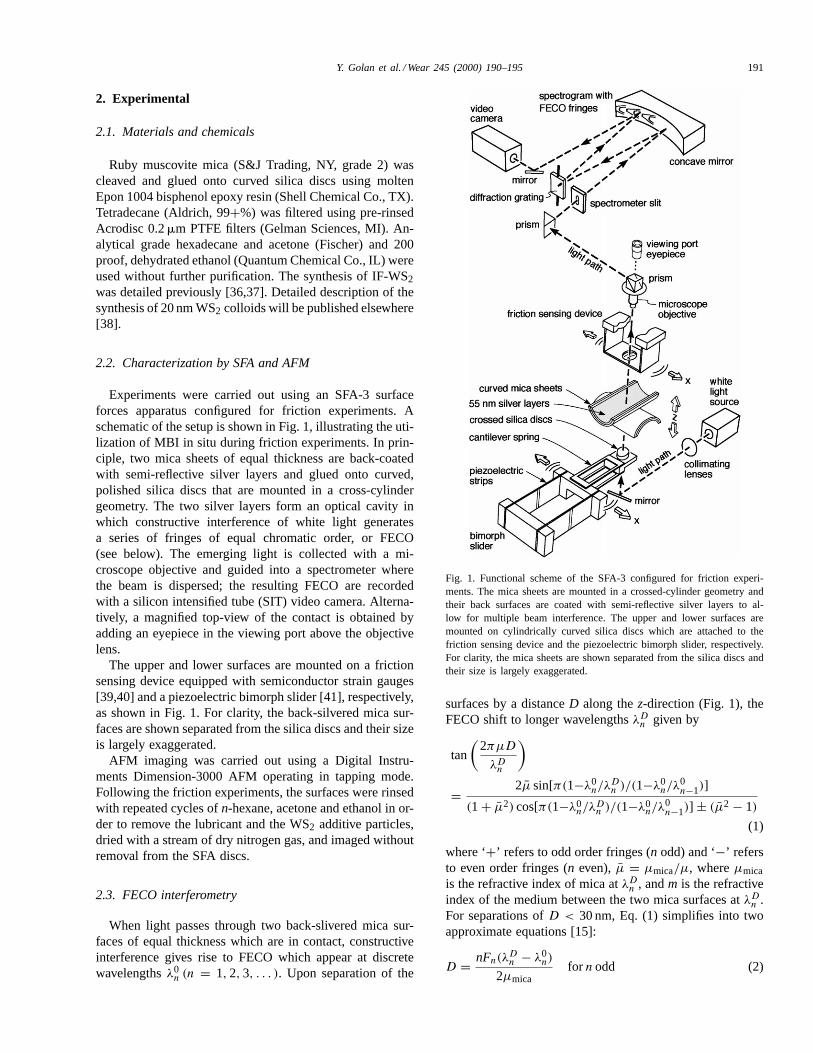
The shape profile of the FECO generated in the SFA isgreatly affected by local deformations of the silvered micasheets, which are mounted on semi-compliant glue layerswith an overall compression modulus of ca. 4× 10¹⁰ Pa. Asformulated above, refractive index variations will also giverise to features in the even FECO, and will affect the oddfringes at separations greater than 30 nm. A schematic il-lustration of the relationship between the morphology of across-section of the contact and the resulting FECO profileis shown in Fig. 2. The FECO profile showing the uniformflattening of two clean mica surfaces in adhesive contact isshown in Fig. 2a. Confinement of, e.g. rounded particles be-tween the surfaces would result in distinct features, as shownin Fig. 2b. Friction induced material transfer, or tribochem-ical formation of transfer layers that are deposited on thesurfaces, could then be detected in real-time using this tech-nique, as shown in Fig. 2c. A real-time video image of theflattened FECO profile obtained with bare mica surfaces in
Fig. 2. Schematic showing the relationship between the morphology ofthe contact and the subsequent shape profile of the fringes of equalchromatic order (FECO) seen in the SFA. (a) Clean mica surfaces inflattened contact (D = 0); (b) same, with about two trapped layers ofIF-WS2 (D ≈ 60 nm); (c) same, with transfer layers formed during afriction experiment with 2H-WS2 platelets in tetradecane (D ≈ 80 nm).
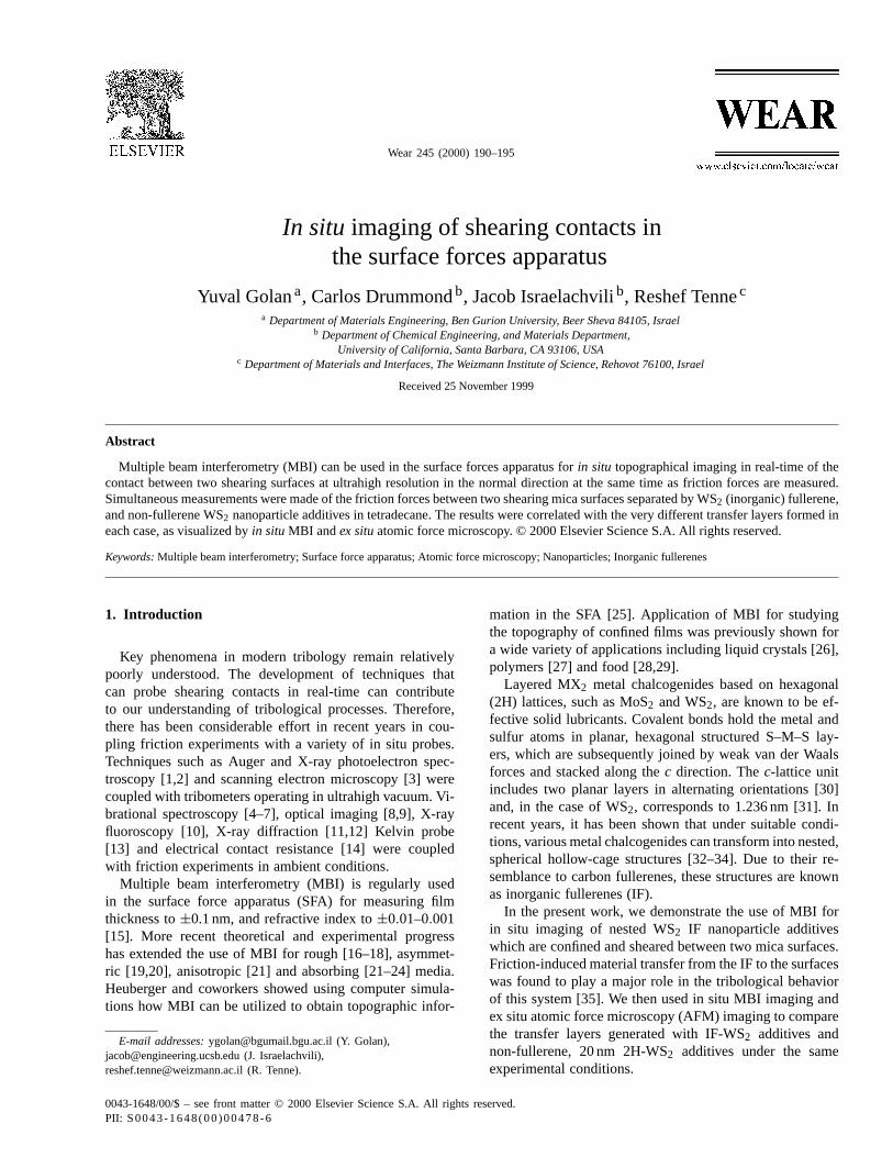
Fig. 3. Fringes of equal chromatic order (FECO) as observed in situ duringfriction experiments with (a) clean mica surfaces in flattened contact(D = 0), and (b) two layers of IF-WS2.
contact is shown in Fig. 3a. The concave fringe shown inthe center of the image is a so-called ‘odd fringe’ (n odd inEqs. (1)–(3)), while the convex fringes on either side of theodd fringe are ‘even fringes’ (n even). Thez-axis in Fig. 3represents the wavelength, which is proportional to the sep-arationD along thez-direction. Thex-axis represents lateraldisplacement along a cross-section through the contact; theflattened parts of the fringes correspond to a contact diam-eter of ca. 40mm. The vertical bright lines in the image areHg reference lines that are used for calibrating thez-axis interms of absolute wavelength. Note that the birefringence ofmica gives rise to some broadening of the fringe width inall the MBI patterns shown in this work.
Recent calculations have shown [42,43] that the lateraldeformations of the mica sheets arising from small normaldeformations allow the detection of local features that aremuch smaller than the theoretical lateral resolution limit(which is of the order of the wavelength of visible light).This can allow the detection of, e.g. 20–30 nm IF-WS2 par-ticles confined between the surfaces (Fig. 3b). Moreover,real-time MBI imaging of the contact along the shear direc-tion when the lower surface is sliding at a known, constantvelocity (cf. Figs. 1 and 2b) can provide quantitative infor-mation on the motion of the trapped particles. By measuringthe velocity of a particular feature on the fringe profile alongthe shear direction (at known magnification) and comparingthis to the drive velocity, it is possible to determine whether
Y. Golan et al. / Wear 245 (2000) 190–195 193
rolling or slipping is occurring and at which surface. Hence,MBI imaging can be used to distinguish between (1) a fea-ture attached to the upper surface that is shearing againstthe lower surface (the feature will appear static), (2) a fea-ture attached to the lower surface and shearing against theupper surface (which will appear to be moving at the drivevelocity), and (3) a feature which is rolling symmetricallybetween the two surfaces (which will appear to be mov-ing at half the drive velocity). Analysis of the IF-WS2 datashowed type (1) and type (2) behavior, with no evidence for‘rolling friction’ which was previously speculated to occurwith spherical nanoparticles.
3.2. Characterization of transfer films
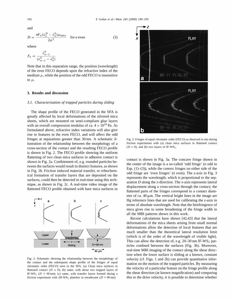
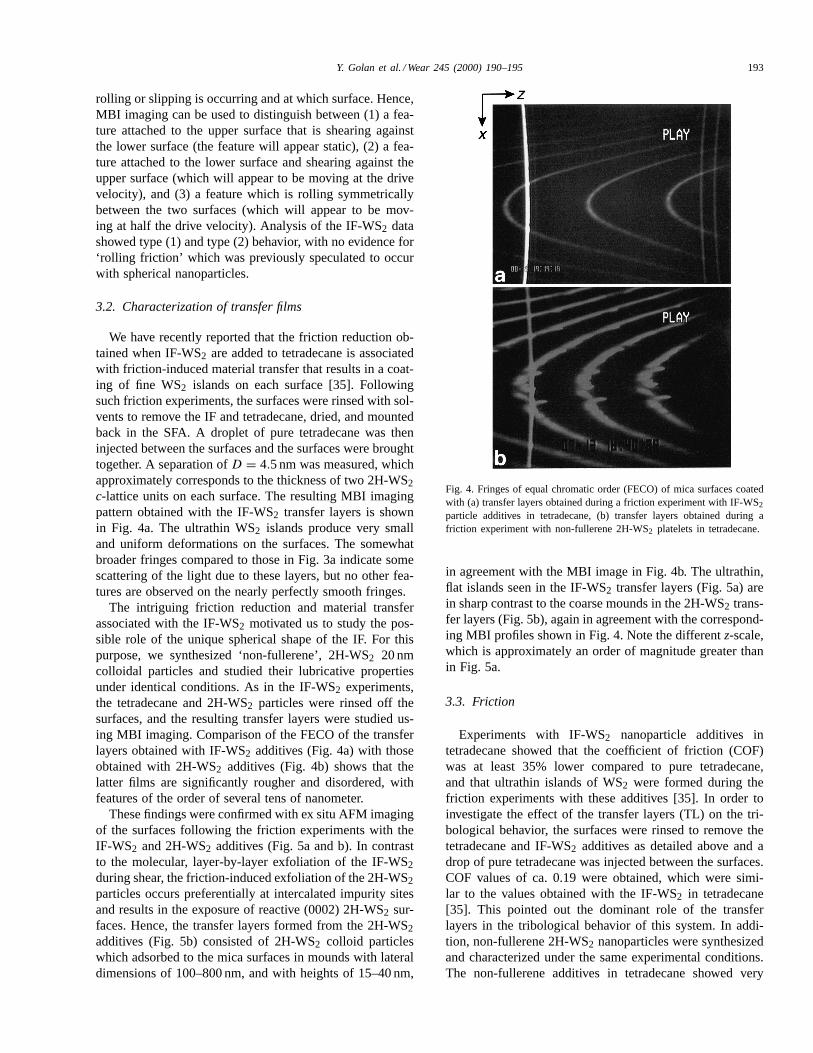
We have recently reported that the friction reduction ob-tained when IF-WS2 are added to tetradecane is associatedwith friction-induced material transfer that results in a coat-ing of fine WS2 islands on each surface [35]. Followingsuch friction experiments, the surfaces were rinsed with sol-vents to remove the IF and tetradecane, dried, and mountedback in the SFA. A droplet of pure tetradecane was theninjected between the surfaces and the surfaces were broughttogether. A separation ofD = 4.5 nm was measured, whichapproximately corresponds to the thickness of two 2H-WS2c-lattice units on each surface. The resulting MBI imagingpattern obtained with the IF-WS2 transfer layers is shownin Fig. 4a. The ultrathin WS2 islands produce very smalland uniform deformations on the surfaces. The somewhatbroader fringes compared to those in Fig. 3a indicate somescattering of the light due to these layers, but no other fea-tures are observed on the nearly perfectly smooth fringes.
The intriguing friction reduction and material transferassociated with the IF-WS2 motivated us to study the pos-sible role of the unique spherical shape of the IF. For thispurpose, we synthesized ‘non-fullerene’, 2H-WS2 20 nmcolloidal particles and studied their lubricative propertiesunder identical conditions. As in the IF-WS2 experiments,the tetradecane and 2H-WS2 particles were rinsed off thesurfaces, and the resulting transfer layers were studied us-ing MBI imaging. Comparison of the FECO of the transferlayers obtained with IF-WS2 additives (Fig. 4a) with thoseobtained with 2H-WS2 additives (Fig. 4b) shows that thelatter films are significantly rougher and disordered, withfeatures of the order of several tens of nanometer.
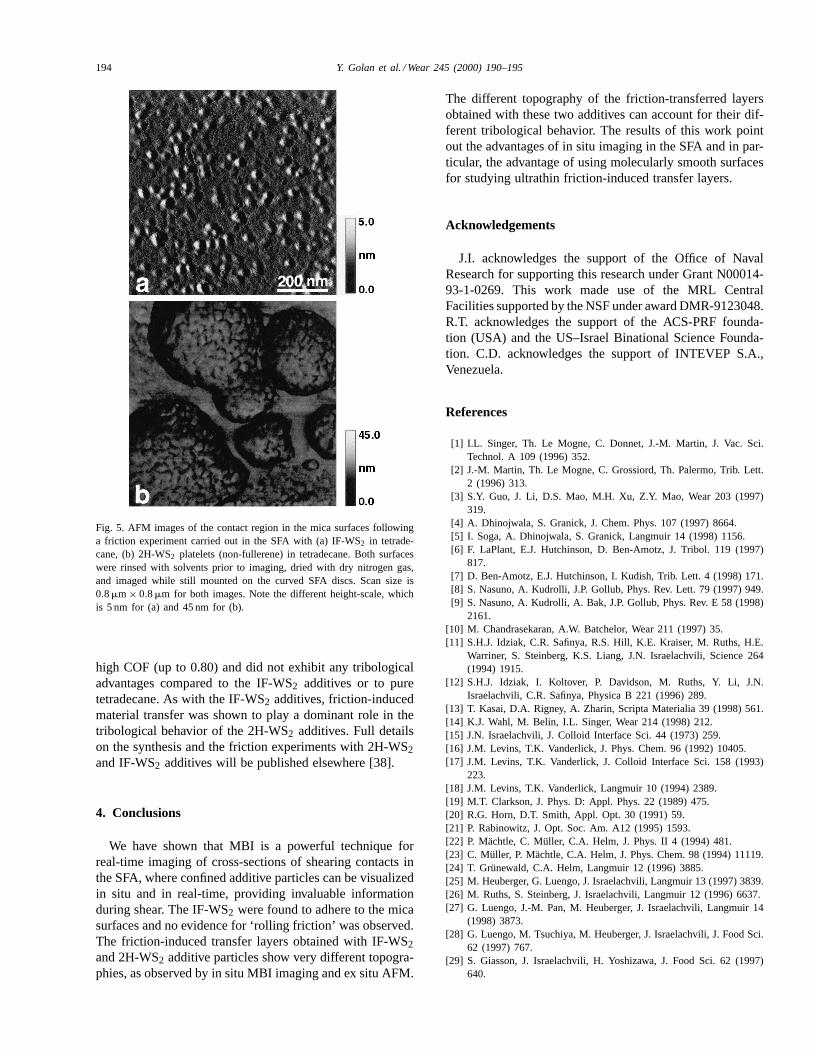
These findings were confirmed with ex situ AFM imagingof the surfaces following the friction experiments with theIF-WS2 and 2H-WS2 additives (Fig. 5a and b). In contrastto the molecular, layer-by-layer exfoliation of the IF-WS2during shear, the friction-induced exfoliation of the 2H-WS2particles occurs preferentially at intercalated impurity sitesand results in the exposure of reactive (0002) 2H-WS2 sur-faces. Hence, the transfer layers formed from the 2H-WS2additives (Fig. 5b) consisted of 2H-WS2 colloid particleswhich adsorbed to the mica surfaces in mounds with lateraldimensions of 100–800 nm, and with heights of 15–40 nm,
Fig. 4. Fringes of equal chromatic order (FECO) of mica surfaces coatedwith (a) transfer layers obtained during a friction experiment with IF-WS2
particle additives in tetradecane, (b) transfer layers obtained during afriction experiment with non-fullerene 2H-WS2 platelets in tetradecane.
in agreement with the MBI image in Fig. 4b. The ultrathin,flat islands seen in the IF-WS2 transfer layers (Fig. 5a) arein sharp contrast to the coarse mounds in the 2H-WS2 trans-fer layers (Fig. 5b), again in agreement with the correspond-ing MBI profiles shown in Fig. 4. Note the differentz-scale,which is approximately an order of magnitude greater thanin Fig. 5a.
3.3. Friction
Experiments with IF-WS2 nanoparticle additives intetradecane showed that the coefficient of friction (COF)was at least 35% lower compared to pure tetradecane,and that ultrathin islands of WS2 were formed during thefriction experiments with these additives [35]. In order toinvestigate the effect of the transfer layers (TL) on the tri-bological behavior, the surfaces were rinsed to remove thetetradecane and IF-WS2 additives as detailed above and adrop of pure tetradecane was injected between the surfaces.COF values of ca. 0.19 were obtained, which were simi-lar to the values obtained with the IF-WS2 in tetradecane[35]. This pointed out the dominant role of the transferlayers in the tribological behavior of this system. In addi-tion, non-fullerene 2H-WS2 nanoparticles were synthesizedand characterized under the same experimental conditions.The non-fullerene additives in tetradecane showed very
194 Y. Golan et al. / Wear 245 (2000) 190–195
Fig. 5. AFM images of the contact region in the mica surfaces followinga friction experiment carried out in the SFA with (a) IF-WS2 in tetrade-cane, (b) 2H-WS2 platelets (non-fullerene) in tetradecane. Both surfaceswere rinsed with solvents prior to imaging, dried with dry nitrogen gas,and imaged while still mounted on the curved SFA discs. Scan size is0.8mm × 0.8mm for both images. Note the different height-scale, whichis 5 nm for (a) and 45 nm for (b).
high COF (up to 0.80) and did not exhibit any tribologicaladvantages compared to the IF-WS2 additives or to puretetradecane. As with the IF-WS2 additives, friction-inducedmaterial transfer was shown to play a dominant role in thetribological behavior of the 2H-WS2 additives. Full detailson the synthesis and the friction experiments with 2H-WS2and IF-WS2 additives will be published elsewhere [38].
4. Conclusions
We have shown that MBI is a powerful technique forreal-time imaging of cross-sections of shearing contacts inthe SFA, where confined additive particles can be visualizedin situ and in real-time, providing invaluable informationduring shear. The IF-WS2 were found to adhere to the micasurfaces and no evidence for ‘rolling friction’ was observed.The friction-induced transfer layers obtained with IF-WS2and 2H-WS2 additive particles show very different topogra-phies, as observed by in situ MBI imaging and ex situ AFM.
The different topography of the friction-transferred layersobtained with these two additives can account for their dif-ferent tribological behavior. The results of this work pointout the advantages of in situ imaging in the SFA and in par-ticular, the advantage of using molecularly smooth surfacesfor studying ultrathin friction-induced transfer layers.
Acknowledgements
J.I. acknowledges the support of the Office of NavalResearch for supporting this research under Grant N00014-93-1-0269. This work made use of the MRL CentralFacilities supported by the NSF under award DMR-9123048.R.T. acknowledges the support of the ACS-PRF founda-tion (USA) and the US–Israel Binational Science Founda-tion. C.D. acknowledges the support of INTEVEP S.A.,Venezuela.
References
[1] I.L. Singer, Th. Le Mogne, C. Donnet, J.-M. Martin, J. Vac. Sci.Technol. A 109 (1996) 352.
[2] J.-M. Martin, Th. Le Mogne, C. Grossiord, Th. Palermo, Trib. Lett.2 (1996) 313.
[3] S.Y. Guo, J. Li, D.S. Mao, M.H. Xu, Z.Y. Mao, Wear 203 (1997)319.
[4] A. Dhinojwala, S. Granick, J. Chem. Phys. 107 (1997) 8664.[5] I. Soga, A. Dhinojwala, S. Granick, Langmuir 14 (1998) 1156.[6] F. LaPlant, E.J. Hutchinson, D. Ben-Amotz, J. Tribol. 119 (1997)
817.[7] D. Ben-Amotz, E.J. Hutchinson, I. Kudish, Trib. Lett. 4 (1998) 171.[8] S. Nasuno, A. Kudrolli, J.P. Gollub, Phys. Rev. Lett. 79 (1997) 949.[9] S. Nasuno, A. Kudrolli, A. Bak, J.P. Gollub, Phys. Rev. E 58 (1998)
2161.[10] M. Chandrasekaran, A.W. Batchelor, Wear 211 (1997) 35.[11] S.H.J. Idziak, C.R. Safinya, R.S. Hill, K.E. Kraiser, M. Ruths, H.E.
Warriner, S. Steinberg, K.S. Liang, J.N. Israelachvili, Science 264(1994) 1915.
[12] S.H.J. Idziak, I. Koltover, P. Davidson, M. Ruths, Y. Li, J.N.Israelachvili, C.R. Safinya, Physica B 221 (1996) 289.
[13] T. Kasai, D.A. Rigney, A. Zharin, Scripta Materialia 39 (1998) 561.[14] K.J. Wahl, M. Belin, I.L. Singer, Wear 214 (1998) 212.[15] J.N. Israelachvili, J. Colloid Interface Sci. 44 (1973) 259.[16] J.M. Levins, T.K. Vanderlick, J. Phys. Chem. 96 (1992) 10405.[17] J.M. Levins, T.K. Vanderlick, J. Colloid Interface Sci. 158 (1993)
223.[18] J.M. Levins, T.K. Vanderlick, Langmuir 10 (1994) 2389.[19] M.T. Clarkson, J. Phys. D: Appl. Phys. 22 (1989) 475.[20] R.G. Horn, D.T. Smith, Appl. Opt. 30 (1991) 59.[21] P. Rabinowitz, J. Opt. Soc. Am. A12 (1995) 1593.[22] P. Mächtle, C. Müller, C.A. Helm, J. Phys. II 4 (1994) 481.[23] C. Müller, P. Mächtle, C.A. Helm, J. Phys. Chem. 98 (1994) 11119.[24] T. Grünewald, C.A. Helm, Langmuir 12 (1996) 3885.[25] M. Heuberger, G. Luengo, J. Israelachvili, Langmuir 13 (1997) 3839.[26] M. Ruths, S. Steinberg, J. Israelachvili, Langmuir 12 (1996) 6637.[27] G. Luengo, J.-M. Pan, M. Heuberger, J. Israelachvili, Langmuir 14
(1998) 3873.[28] G. Luengo, M. Tsuchiya, M. Heuberger, J. Israelachvili, J. Food Sci.
62 (1997) 767.[29] S. Giasson, J. Israelachvili, H. Yoshizawa, J. Food Sci. 62 (1997)
640.
Y. Golan et al. / Wear 245 (2000) 190–195 195
[30] R.W.G. Wyckoff, Crystal Structures, 2nd Edition, Vol. 1, IntersciencePublishers, New York,1963, pp. 280–282.
[31] Powder Diffraction File (Inorganic Volume) No. 8-237 (tungstensulfide), JCPDS — International Center for Diffraction Data.
[32] R. Tenne, L. Margulis, M. Genut, G. Hodes, Nature 360 (1992) 444.[33] R. Tenne, Adv. Mater. 7 (1995) 965.[34] L. Rapoport, Y. Bilik, M. Homyonfer, S.R. Cohen, R. Tenne, Nature
387 (1997) 791.[35] Y. Golan, C. Drummond, M. Homyonfer, Y. Feldman, R. Tenne, J.
Israelachvili, Adv. Mater. 11 (1999) 934.[36] Y. Feldman, E. Waserman, D.J. Srolovitz, R. Tenne, Science 267
(1995) 222.
[37] Y. Feldman, G.L. Frey, M. Homyonfer, V. Lyakhovitskaya, L.Margulis, H. Cohen, G. Hodes, J.L. Hutchison, R. Tenne, J. Am.Chem. Soc. 117 (1996) 5362.
[38] C. Drummond et al., in preparation.[39] A.M. Homola, J. Israelachvili, M.L. Gee, P.M. McGuiggan, J. Tribol.
111 (1989) 675.[40] B. Bhushan, J. Israelachvili, U. Landman, Nature 374 (1995) 607.[41] G. Luengo, F.-J. Schmitt, R. Hill, J. Israelachvili, Macromolecules
30 (1997) 2482.[42] K. Johnson, personal communication.[43] R. Stengl, K. Mitani, V. Lehmann, U. Gösele, in: Proceedings of
IEEE SOS/SOI Technology Conference, 1989, p. 123.