Embed Size (px)
Citation preview
In-Sight® 7000 SeriesVision SystemInstallationManual


Legal NoticesThe software described in this document is furnished under license, and may be used or copied only in accordance withthe terms of such license and with the inclusion of the copyright notice shown on this page. Neither the software, thisdocument, nor any copies thereof may be provided to, or otherwise made available to, anyone other than the licensee.Title to, and ownership of, this software remains with Cognex Corporation or its licensor. Cognex Corporation assumesno responsibility for the use or reliability of its software on equipment that is not supplied by Cognex Corporation.Cognex Corporation makes no warranties, either express or implied, regarding the described software, itsmerchantability, non-infringement or its fitness for any particular purpose.
The information in this document is subject to change without notice and should not be construed as a commitment byCognex Corporation. Cognex Corporation is not responsible for any errors that may be present in either this document orthe associated software.
Companies, names, and data used in examples herein are fictitious unless otherwise noted. No part of this documentmay be reproduced or transmitted in any form or by any means, electronic or mechanical, for any purpose, nortransferred to any other media or language without the written permission of Cognex Corporation.
Cognex P/N 597-0138-01 Rev. C
Copyright © 2011 - 2013 Cognex Corporation. All Rights Reserved.
Portions of the hardware and software provided by Cognex may be covered by one or more of the U.S. and foreignpatents listed below as well as pending U.S. and foreign patents. Such pending U.S. and foreign patents issued after thedate of this document are listed on the Cognex web site at: http://www.cognex.com/patents.
5481712, 5742037, 5751853, 5845007, 5909504, 5943441, 5949905, 5960125, 5978080, 5978081, 6005978,6137893, 6141033, 6154567, 6215915, 6301396, 6327393, 6381375, 6408109, 6457032, 6490600, 6563324,6658145, 6690842, 6771808, 6804416, 6836567, 6850646, 6856698, 6859907, 6920241, 6941026, 6959112,6963338, 6975764, 6985625, 6993192, 7006712, 7016539, 7043081, 7058225, 7065262, 7069499, 7088862,7107519, 7164796, 7175090, 7181066, 7251366, 7720315, JP 3927239
Cognex, In-Sight, EasyBuilder, VisionView, DataMan and DVT are registered trademarks of Cognex Corporation.
The Cognex logo, SmartLink, EdgeCount, FeatureCount, and ObjectLocate are trademarks of Cognex Corporation.
Windows is a registered trademark or trademark of Microsoft Corporation in the United States and other countries. Otherproduct and company trademarks identified herein are the trademarks of their respective owners.
i

ii
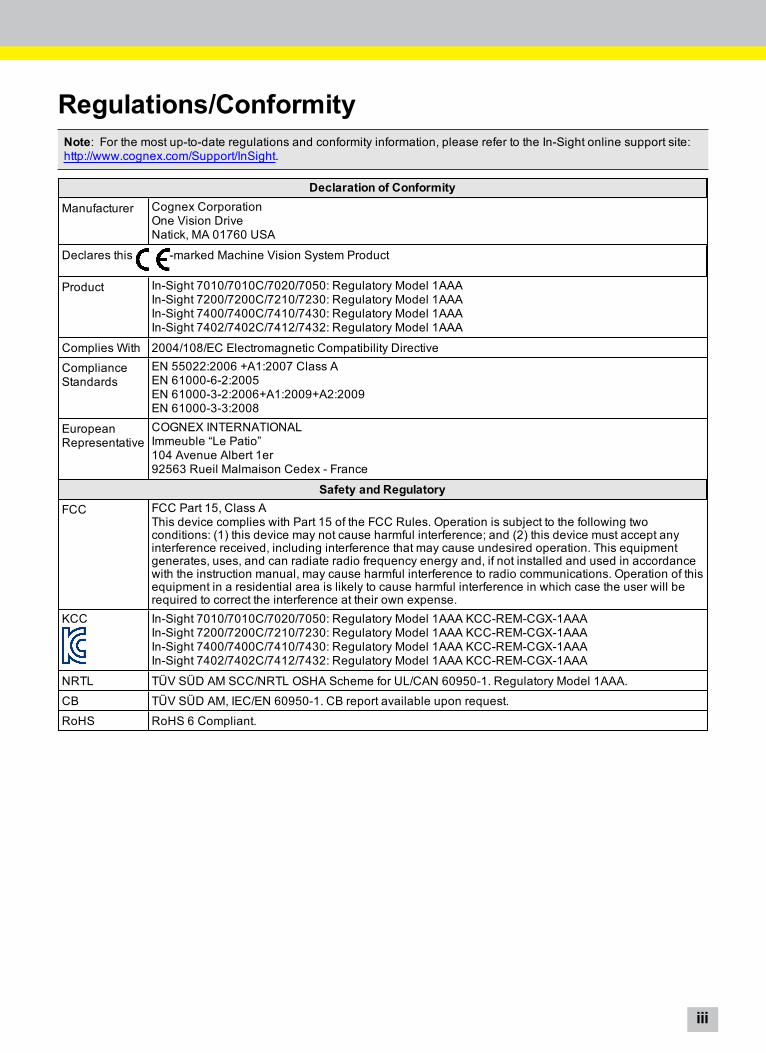
Regulations/ConformityNote: For the most up-to-date regulations and conformity information, please refer to the In-Sight online support site:http://www.cognex.com/Support/InSight.
Declaration of ConformityManufacturer Cognex Corporation
One Vision DriveNatick, MA 01760 USA
Declares this -marked Machine Vision System Product
Product In-Sight 7010/7010C/7020/7050: Regulatory Model 1AAAIn-Sight 7200/7200C/7210/7230: Regulatory Model 1AAAIn-Sight 7400/7400C/7410/7430: Regulatory Model 1AAAIn-Sight 7402/7402C/7412/7432: Regulatory Model 1AAA
Complies With 2004/108/EC Electromagnetic Compatibility Directive
ComplianceStandards
EN 55022:2006 +A1:2007 Class AEN 61000-6-2:2005EN 61000-3-2:2006+A1:2009+A2:2009EN 61000-3-3:2008
EuropeanRepresentative
COGNEX INTERNATIONALImmeuble “Le Patio”104 Avenue Albert 1er92563 Rueil Malmaison Cedex - France
Safety and RegulatoryFCC FCC Part 15, Class A
This device complies with Part 15 of the FCC Rules. Operation is subject to the following twoconditions: (1) this device may not cause harmful interference; and (2) this device must accept anyinterference received, including interference that may cause undesired operation. This equipmentgenerates, uses, and can radiate radio frequency energy and, if not installed and used in accordancewith the instruction manual, may cause harmful interference to radio communications. Operation of thisequipment in a residential area is likely to cause harmful interference in which case the user will berequired to correct the interference at their own expense.
KCC In-Sight 7010/7010C/7020/7050: Regulatory Model 1AAA KCC-REM-CGX-1AAAIn-Sight 7200/7200C/7210/7230: Regulatory Model 1AAA KCC-REM-CGX-1AAAIn-Sight 7400/7400C/7410/7430: Regulatory Model 1AAA KCC-REM-CGX-1AAAIn-Sight 7402/7402C/7412/7432: Regulatory Model 1AAA KCC-REM-CGX-1AAA
NRTL TÜV SÜD AM SCC/NRTL OSHA Scheme for UL/CAN 60950-1. Regulatory Model 1AAA.
CB TÜV SÜD AM, IEC/EN 60950-1. CB report available upon request.
RoHS RoHS 6 Compliant.
iii

iv
PrecautionsObserve these precautions when installing the vision system to reduce the risk of injury or equipment damage:
l The In-Sight vision system is intended to be supplied by a UL or NRTL listed power supply with a 24VDC outputrated for at least 2A continuous and a maximum short circuit current rating of less than 8A and a maximum powerrating of less than 100VA and marked Class 2 or Limited Power Source (LPS). Any other voltage creates a risk offire or shock and can damage the components. Applicable national and local wiring standards and rules must befollowed.
l According to IEC 62471, the white ring light is in Risk Group 1; it is not recommended to stare directly into theillumination LEDs when the vision system is receiving power. According to IEC 62471, the blue ring light is inRisk Group 2; CAUTION – Possibly hazardous optical radiation emitted from this product. Do not stare atoperating light. May be harmful to the eyes. The green ring light, the red ring light and the Infrared (IR) ring lightare Exempt Group products, therefore no precautions are required.
l Do not install In-Sight vision systems where they are directly exposed to environmental hazards such asexcessive heat, dust, moisture, humidity, impact, vibration, corrosive substances, flammable substances, or staticelectricity.
l To reduce the risk of damage or malfunction due to over-voltage, line noise, electrostatic discharge (ESD), powersurges, or other irregularities in the power supply, route all cables and wires away from high-voltage powersources.
l Do not expose the image sensor to laser light; image sensors can be damaged by direct, or reflected, laser light.If your application requires the use of laser light that may strike the image sensor, a lens filter at thecorresponding laser's wavelength is recommended. Contact your local integrator or application engineer forsuggestions.
l The In-Sight vision system does not contain user-serviceable parts. Do not make electrical or mechanicalmodifications to In-Sight vision system components. Unauthorized modifications may void your warranty.
l Changes or modifications not expressly approved by the party responsible for regulatory compliance could voidthe user’s authority to operate the equipment.
l Service loops should be included with all cable connections.
l Cable shielding can be degraded or cables can be damaged or wear out more quickly if a bend radius or serviceloop is tighter than 10X the cable diameter.
l Class A Equipment (broadcasting and communication equipment for office work): Seller and user shall benotified that this equipment is suitable for electromagnetic equipment for office work (Class A) and can be usedoutside the home.
l This device should be used in accordance with the instructions in this manual.
v

vi
Table of ContentsLegal Notices iRegulations/Conformity iiiPrecautions vIntroduction 1Support 1Standard Components 1Cables 2Ethernet Cable 2Light Cable 2Power and I/O Breakout Cable 2
Installation 3Connectors and Indicators 3Install the Lens (C-Mount Lens Configuration) 5Mount the Vision System 6Working Distance and Field of View 7Connect the Light Cable (Optional) 9Connect the Ethernet Cable 9Connect the Power and I/O Breakout Cable 10
Specifications 11Vision System Specifications 11I/O Specifications 13Acquisition Trigger Input 13General-Purpose Inputs 14High-SpeedOutputs 16RS-232 Receive and Transmit 18RS-232 Connector Configuration 18Light Connector 19Ethernet Cable Specifications 20Light Cable Specifications 21Power and I/O Breakout Cable Specifications 22
Vision System Dimensions 23
Appendix A - Cleaning/Maintenance 27Clean the Vision System Housing 27Clean the Vision System Image SensorWindow (C-Mount Lens Configuration) 27
Appendix B - Connect the I/O Module 29
vii

viii
IntroductionThe In-Sight® vision system is a compact, network-ready, stand-alone machine vision system used for automatedinspection, measurement, identification and robot guidance applications on the factory floor. All models can be easilyconfigured remotely over a network using an intuitive user interface.
SupportMany information resources are available to assist you in using the vision system:
l In-Sight® Explorer Help, an online HTML Help file provided with In-Sight Explorer software.
l In-Sight computer-based tutorials provided on CD-ROM with selected In-Sight starter accessories kits.
l The In-Sight online support site: http://www.cognex.com/Support/InSight.
Standard ComponentsThe vision system is shipped with the components listed below.
Table 1-1: Standard Components
Component M12 Lens Configuration C-Mount Lens ConfigurationVision System X X
Lens X
Lens Cover Kit (includes lens cover and O-Ring) X X
LED Ring Light X
Mounting Kit X
Table 1-2: Standard Components Descriptions
Component DescriptionVision System Provides vision processing, job storage, serial and Ethernet connectivity and discrete
I/O.
Lens Provides image formation. The vision system is shipped with the lens pre-installedwith the M12 lens configuration.
Note: If you purchased a vision system with the pre-installed M12 lens, the lens canbe replaced with other M12 lenses. The Cognex Lens Tool accessory (LNS-M12-TOOLKIT) must be used to replace the M12 lens. Please contact your Cognex salesrepresentative for more information.
Lens Cover Kit (includes lenscover and O-Ring)
Provides environmental protection for the lens.
LED Ring Light Provides internal lighting. The vision system is shipped with an internal LED ring lightpre-installed with the M12 lens configuration.
Mounting Kit Includes a mounting bracket and M3 screws (quantity 4) for mounting the visionsystem and securing it to a mounting surface.
1
CablesNote: Cables are sold separately.
CAUTION: All cable connectors are “keyed” to fit the connectors on the vision system; do not force the connections ordamage may occur.
Ethernet CableThe Ethernet cable is used to connect the vision system to other network devices. The pin-outs for the cable are listed inthe Ethernet Cable Specifications on page 20. This cable is available in the lengths and styles listed below.
Table 1-3: Ethernet Cables
Length Standard Part # 45-Degree Key Right-Angle Part # 135-Degree Key Right Angle Part #0.6 m CCB-84901-1001-00 N/A N/A2 m CCB-84901-1002-02 CCB-84901-6005-02 CCB-84901-7005-025 m CCB-84901-1003-05 CCB-84901-6001-05 CCB-84901-7001-0510 m CCB-84901-1004-10 CCB-84901-6002-10 CCB-84901-7002-1015 m CCB-84901-1005-15 CCB-84901-6003-15 CCB-84901-7003-1530 m CCB-84901-1006-30 CCB-84901-6004-30 CCB-84901-7004-30
Light CableThe Light cable is used to connect the vision system to an external lighting device, providing power and strobe control.The pin-outs for the cable are listed in the Light Cable Specifications on page 21. This cable is available in the lengthslisted below.
Table 1-4: Light Cables
Length Standard Part #0.5 m CCB-M12LTF-001 m CCB-M12LTF-012 m CCB-M12LTF-025 m CCB-M12LTF-05
Power and I/O Breakout CableThe Power and I/O Breakout cable provides connections to an external power supply, the acquisition trigger input,general-purpose inputs, high-speed outputs, and RS-232 serial communications. The pin-outs for the cable are listed inthe Power and I/O Breakout Cable Specifications on page 22. This cable is available in the styles listed below.
Table 1-5: Power and I/O Breakout Cables
Length Standard Part # Right-Angle Part #5 m CCB-PWRIO-05 CCB-PWRIO-05R
2
InstallationThis section describes the connection of the vision system to its standard and optional components. For a complete list ofoptions and accessories, contact your Cognex sales representative.
Note:l Cables are sold separately.
l If any of the standard components appear to be missing or damaged, immediately contact your CognexAuthorized Service Provider (ASP) or Cognex Technical Support.
CAUTION: All cable connectors are “keyed” to fit the connectors on the vision system; do not force the connections ordamage may occur.
Connectors and IndicatorsTable 2-1: Vision System Connectors
Connector FunctionENET Connector Connects the vision system to a network. The ENET connector provides the Ethernet
connection to external network devices. For more information, refer to the Ethernet CableSpecifications on page 20.
LIGHT Connector Connects the vision system to an external lighting device. For more information, refer to theLight Cable Specifications on page 21.
PWR Connector Connects the Power and I/O Breakout cable, which provides connections to an externalpower supply, the acquisition trigger input, general-purpose inputs, high-speed outputs, andRS-232 serial communications. For more information, refer to the Power and I/O BreakoutCable Specifications on page 22.
3
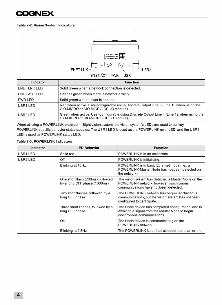
Table 2-2: Vision System Indicators
Indicator FunctionENET LNK LED Solid green when a network connection is detected.
ENET ACT LED Flashes green when there is network activity.
PWR LED Solid green when power is applied.
USR1 LED Red when active. User-configurable using Discrete Output Line 5 (Line 13 when using theCIO-MICRO or CIO-MICRO-CC I/O module).
USR2 LED Green when active. User-configurable using Discrete Output Line 4 (Line 12 when using theCIO-MICRO or CIO-MICRO-CC I/O module).
When utilizing a POWERLINK-enabled In-Sight vision system, the vision system's LEDs are used to conveyPOWERLINK-specific behavior status updates. The USR1 LED is used as the POWERLINK error LED, and the USR2LED is used as POWERLINK status LED.
Table 2-3: POWERLINK Indicators
Indicator LED Behavior FunctionUSR1 LED Solid red POWERLINK is in an error state.
USR2 LED Off POWERLINK is initializing.
Blinking at 10Hz POWERLINK is in basic Ethernet mode (i.e., aPOWERLINK Master Node has not been detected onthe network).
One short flash (200ms), followedby a long OFF phase (1000ms)
The vision system has detected a Master Node on thePOWERLINK network, however, isochronouscommunications have not been detected.
Two short flashes, followed by along OFF phase
The POWERLINK network has begun isochronouscommunications, but the vision system has not beenconfigured to participate.
Three short flashes, followed by along OFF phase
The Node device has completed configuration, and isawaiting a signal from the Master Node to beginisochronous communications.
On The Node device is communicating on thePOWERLINK network.
Blinking at 2.5Hz The POWERLINK Node has stopped due to an error.
4
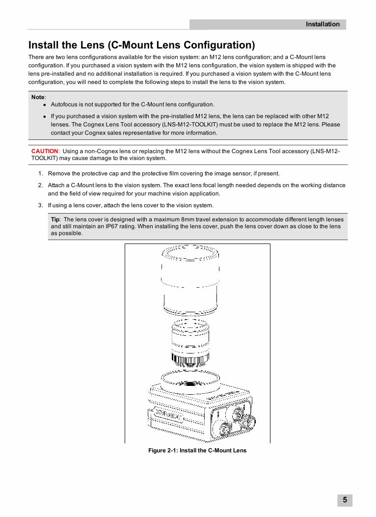
Install the Lens (C-Mount Lens Configuration)There are two lens configurations available for the vision system: an M12 lens configuration; and a C-Mount lensconfiguration. If you purchased a vision system with the M12 lens configuration, the vision system is shipped with thelens pre-installed and no additional installation is required. If you purchased a vision system with the C-Mount lensconfiguration, you will need to complete the following steps to install the lens to the vision system.
Note:l Autofocus is not supported for the C-Mount lens configuration.
l If you purchased a vision system with the pre-installed M12 lens, the lens can be replaced with other M12lenses. The Cognex Lens Tool accessory (LNS-M12-TOOLKIT) must be used to replace the M12 lens. Pleasecontact your Cognex sales representative for more information.
CAUTION: Using a non-Cognex lens or replacing the M12 lens without the Cognex Lens Tool accessory (LNS-M12-TOOLKIT) may cause damage to the vision system.
1. Remove the protective cap and the protective film covering the image sensor, if present.
2. Attach a C-Mount lens to the vision system. The exact lens focal length needed depends on the working distanceand the field of view required for your machine vision application.
3. If using a lens cover, attach the lens cover to the vision system.
Tip: The lens cover is designed with a maximum 8mm travel extension to accommodate different length lensesand still maintain an IP67 rating. When installing the lens cover, push the lens cover down as close to the lensas possible.
Figure 2-1: Install the C-Mount Lens
Installation
5
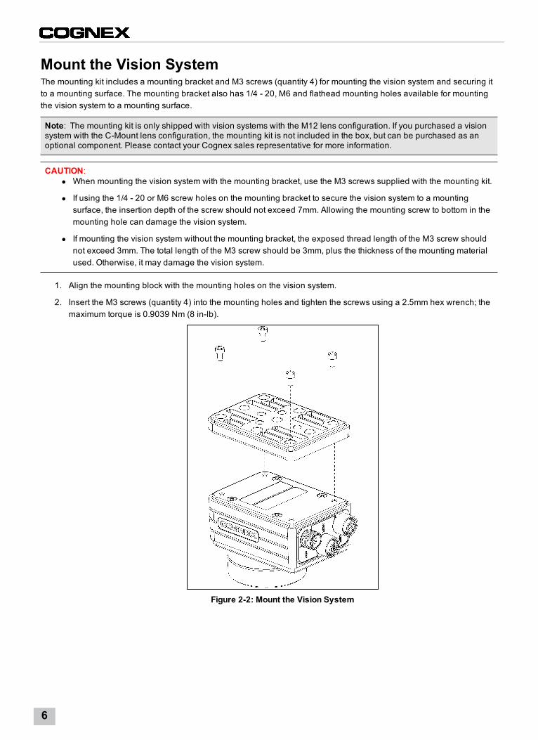
Mount the Vision SystemThe mounting kit includes a mounting bracket and M3 screws (quantity 4) for mounting the vision system and securing itto a mounting surface. The mounting bracket also has 1/4 - 20, M6 and flathead mounting holes available for mountingthe vision system to a mounting surface.
Note: The mounting kit is only shipped with vision systems with the M12 lens configuration. If you purchased a visionsystem with the C-Mount lens configuration, the mounting kit is not included in the box, but can be purchased as anoptional component. Please contact your Cognex sales representative for more information.
CAUTION:l When mounting the vision system with the mounting bracket, use the M3 screws supplied with the mounting kit.
l If using the 1/4 - 20 or M6 screw holes on the mounting bracket to secure the vision system to a mountingsurface, the insertion depth of the screw should not exceed 7mm. Allowing the mounting screw to bottom in themounting hole can damage the vision system.
l If mounting the vision system without the mounting bracket, the exposed thread length of the M3 screw shouldnot exceed 3mm. The total length of the M3 screw should be 3mm, plus the thickness of the mounting materialused. Otherwise, it may damage the vision system.
1. Align the mounting block with the mounting holes on the vision system.
2. Insert the M3 screws (quantity 4) into the mounting holes and tighten the screws using a 2.5mm hex wrench; themaximum torque is 0.9039 Nm (8 in-lb).
Figure 2-2: Mount the Vision System
6
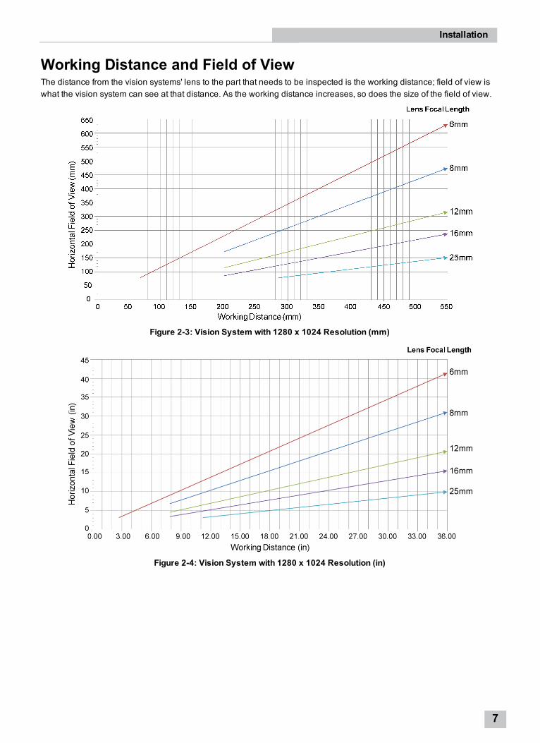
Working Distance and Field of ViewThe distance from the vision systems' lens to the part that needs to be inspected is the working distance; field of view iswhat the vision system can see at that distance. As the working distance increases, so does the size of the field of view.
Figure 2-3: Vision System with 1280 x 1024 Resolution (mm)
Figure 2-4: Vision System with 1280 x 1024 Resolution (in)
Installation
7
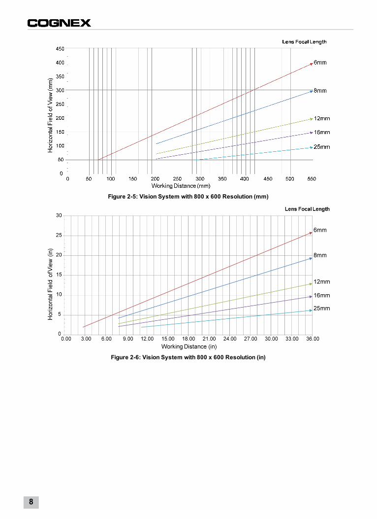
Figure 2-5: Vision System with 800 x 600 Resolution (mm)
Figure 2-6: Vision System with 800 x 600 Resolution (in)
8
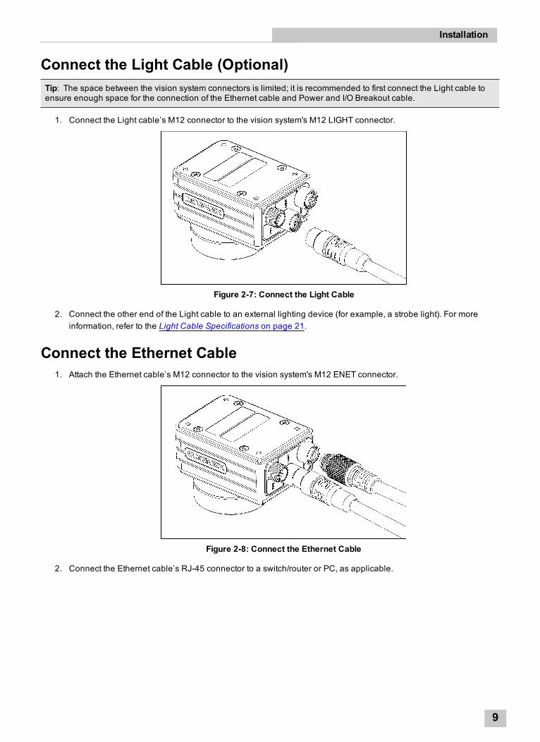
Connect the Light Cable (Optional)Tip: The space between the vision system connectors is limited; it is recommended to first connect the Light cable toensure enough space for the connection of the Ethernet cable and Power and I/O Breakout cable.
1. Connect the Light cable’s M12 connector to the vision system's M12 LIGHT connector.
Figure 2-7: Connect the Light Cable
2. Connect the other end of the Light cable to an external lighting device (for example, a strobe light). For moreinformation, refer to the Light Cable Specifications on page 21.
Connect the Ethernet Cable1. Attach the Ethernet cable’s M12 connector to the vision system's M12 ENET connector.
Figure 2-8: Connect the Ethernet Cable
2. Connect the Ethernet cable’s RJ-45 connector to a switch/router or PC, as applicable.
Installation
9
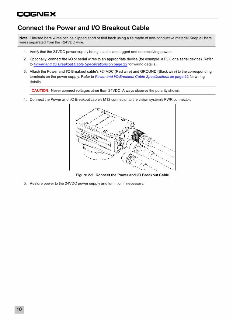
Connect the Power and I/O Breakout CableNote: Unused bare wires can be clipped short or tied back using a tie made of non-conductive material.Keep all barewires separated from the +24VDC wire.
1. Verify that the 24VDC power supply being used is unplugged and not receiving power.
2. Optionally, connect the I/O or serial wires to an appropriate device (for example, a PLC or a serial device). Referto Power and I/O Breakout Cable Specifications on page 22 for wiring details.
3. Attach the Power and I/O Breakout cable's +24VDC (Red wire) and GROUND (Black wire) to the correspondingterminals on the power supply. Refer to Power and I/O Breakout Cable Specifications on page 22 for wiringdetails.
CAUTION: Never connect voltages other than 24VDC. Always observe the polarity shown.
4. Connect the Power and I/O Breakout cable's M12 connector to the vision system's PWR connector.
Figure 2-9: Connect the Power and I/O Breakout Cable
5. Restore power to the 24VDC power supply and turn it on if necessary.
10
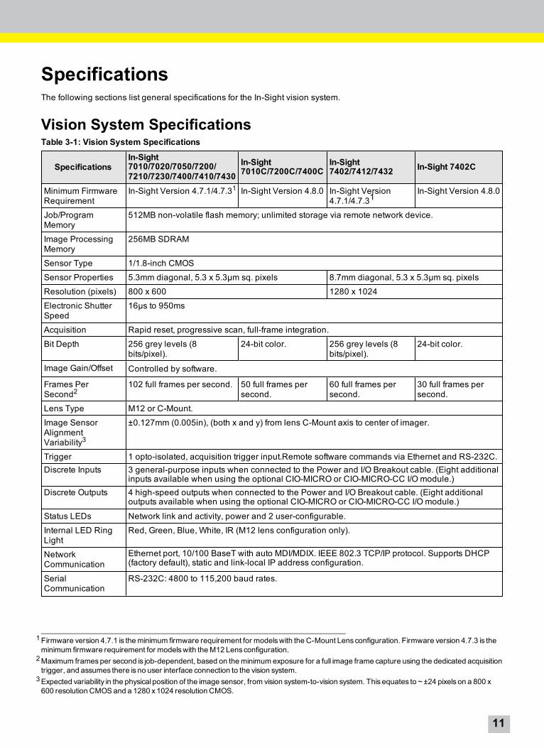
SpecificationsThe following sections list general specifications for the In-Sight vision system.
Vision System SpecificationsTable 3-1: Vision System Specifications
SpecificationsIn-Sight7010/7020/7050/7200/7210/7230/7400/7410/7430
In-Sight7010C/7200C/7400C
In-Sight7402/7412/7432 In-Sight 7402C
Minimum FirmwareRequirement
In-Sight Version 4.7.1/4.7.31 In-Sight Version 4.8.0 In-Sight Version4.7.1/4.7.31
In-Sight Version 4.8.0
Job/ProgramMemory
512MB non-volatile flash memory; unlimited storage via remote network device.
Image ProcessingMemory
256MB SDRAM
Sensor Type 1/1.8-inch CMOS
Sensor Properties 5.3mm diagonal, 5.3 x 5.3µm sq. pixels 8.7mm diagonal, 5.3 x 5.3µm sq. pixels
Resolution (pixels) 800 x 600 1280 x 1024
Electronic ShutterSpeed
16µs to 950ms
Acquisition Rapid reset, progressive scan, full-frame integration.
Bit Depth 256 grey levels (8bits/pixel).
24-bit color. 256 grey levels (8bits/pixel).
24-bit color.
Image Gain/Offset Controlled by software.
Frames PerSecond2
102 full frames per second. 50 full frames persecond.
60 full frames persecond.
30 full frames persecond.
Lens Type M12 or C-Mount.
Image SensorAlignmentVariability3
±0.127mm (0.005in), (both x and y) from lens C-Mount axis to center of imager.
Trigger 1 opto-isolated, acquisition trigger input.Remote software commands via Ethernet and RS-232C.Discrete Inputs 3 general-purpose inputs when connected to the Power and I/O Breakout cable. (Eight additional
inputs available when using the optional CIO-MICRO or CIO-MICRO-CC I/O module.)Discrete Outputs 4 high-speed outputs when connected to the Power and I/O Breakout cable. (Eight additional
outputs available when using the optional CIO-MICRO or CIO-MICRO-CC I/O module.)
Status LEDs Network link and activity, power and 2 user-configurable.
Internal LED RingLight
Red, Green, Blue, White, IR (M12 lens configuration only).
NetworkCommunication
Ethernet port, 10/100 BaseT with auto MDI/MDIX. IEEE 802.3 TCP/IP protocol. Supports DHCP(factory default), static and link-local IP address configuration.
SerialCommunication
RS-232C: 4800 to 115,200 baud rates.
1Firmware version 4.7.1 is theminimum firmware requirement for modelswith the C-Mount Lens configuration. Firmware version 4.7.3 is theminimum firmware requirement for modelswith theM12 Lens configuration.
2Maximum framesper second is job-dependent, based on theminimum exposure for a full image frame capture using the dedicated acquisitiontrigger, and assumes there is no user interface connection to the vision system.
3Expected variability in the physical position of the image sensor, from vision system-to-vision system. This equates to ~ ±24 pixels on a 800 x600 resolution CMOSand a 1280 x1024 resolution CMOS.
11
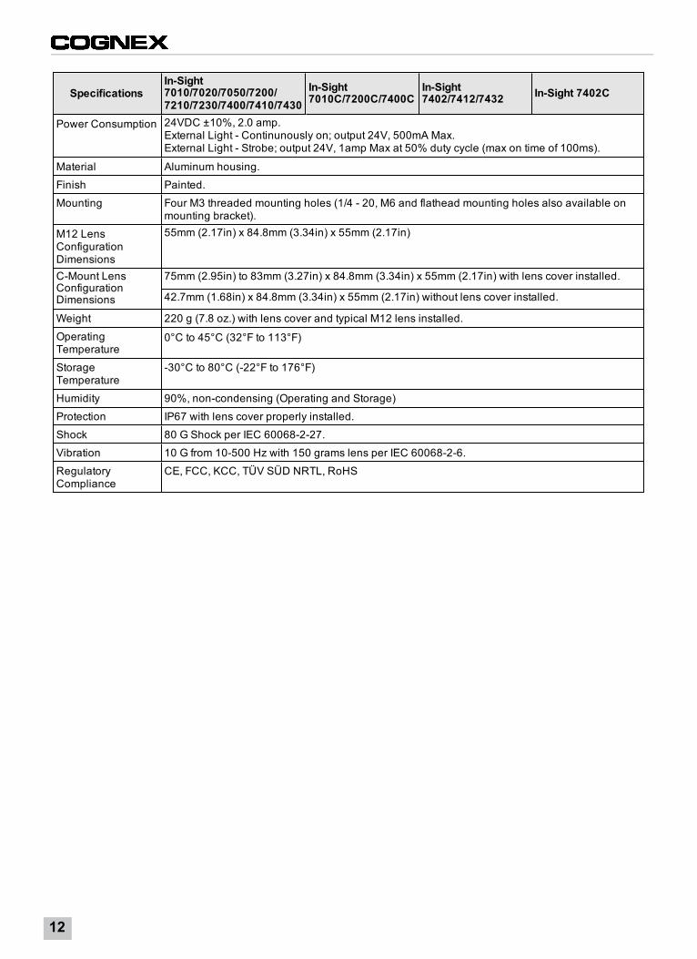
SpecificationsIn-Sight7010/7020/7050/7200/7210/7230/7400/7410/7430
In-Sight7010C/7200C/7400C
In-Sight7402/7412/7432 In-Sight 7402C
Power Consumption 24VDC ±10%, 2.0 amp.External Light - Continunously on; output 24V, 500mA Max.External Light - Strobe; output 24V, 1amp Max at 50% duty cycle (max on time of 100ms).
Material Aluminum housing.
Finish Painted.
Mounting Four M3 threaded mounting holes (1/4 - 20, M6 and flathead mounting holes also available onmounting bracket).
M12 LensConfigurationDimensions
55mm (2.17in) x 84.8mm (3.34in) x 55mm (2.17in)
C-Mount LensConfigurationDimensions
75mm (2.95in) to 83mm (3.27in) x 84.8mm (3.34in) x 55mm (2.17in) with lens cover installed.
42.7mm (1.68in) x 84.8mm (3.34in) x 55mm (2.17in) without lens cover installed.
Weight 220 g (7.8 oz.) with lens cover and typical M12 lens installed.
OperatingTemperature
0°C to 45°C (32°F to 113°F)
StorageTemperature
-30°C to 80°C (-22°F to 176°F)
Humidity 90%, non-condensing (Operating and Storage)
Protection IP67 with lens cover properly installed.
Shock 80 G Shock per IEC 60068-2-27.
Vibration 10 G from 10-500 Hz with 150 grams lens per IEC 60068-2-6.
RegulatoryCompliance
CE, FCC, KCC, TÜV SÜD NRTL, RoHS
12
I/O SpecificationsCable and connector specifications and connection examples for acquisition trigger input, general-purpose inputs, high-speed outputs, RS-232 receive and transmit, and light connectors are provided in the following sections.
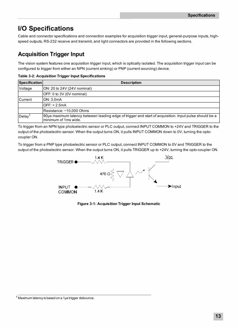
Acquisition Trigger InputThe vision system features one acquisition trigger input, which is optically isolated. The acquisition trigger input can beconfigured to trigger from either an NPN (current sinking) or PNP (current sourcing) device.
Table 3-2: Acquisition Trigger Input Specifications
Specification DescriptionVoltage ON: 20 to 24V (24V nominal)
OFF: 0 to 3V (0V nominal)Current ON: 3.0mA
OFF: < 2.5mAResistance: ~10,000 Ohms
Delay1 90µs maximum latency between leading edge of trigger and start of acquisition. Input pulse should be aminimum of 1ms wide.
To trigger from an NPN type photoelectric sensor or PLC output, connect INPUT COMMON to +24V and TRIGGER to theoutput of the photoelectric sensor. When the output turns ON, it pulls INPUT COMMON down to 0V, turning the opto-coupler ON.
To trigger from a PNP type photoelectric sensor or PLC output, connect INPUT COMMON to 0V and TRIGGER to theoutput of the photoelectric sensor. When the output turns ON, it pulls TRIGGER up to +24V, turning the opto-coupler ON.
Figure 3-1: Acquisition Trigger Input Schematic
1Maximum latency is based on a 1µs trigger debounce.
Specifications
13
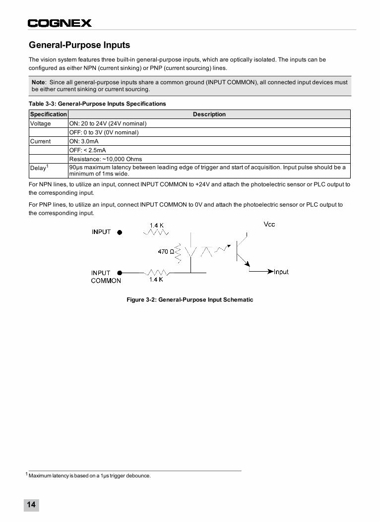
General-Purpose InputsThe vision system features three built-in general-purpose inputs, which are optically isolated. The inputs can beconfigured as either NPN (current sinking) or PNP (current sourcing) lines.
Note: Since all general-purpose inputs share a common ground (INPUT COMMON), all connected input devices mustbe either current sinking or current sourcing.
Table 3-3: General-Purpose Inputs Specifications
Specification DescriptionVoltage ON: 20 to 24V (24V nominal)
OFF: 0 to 3V (0V nominal)Current ON: 3.0mA
OFF: < 2.5mAResistance: ~10,000 Ohms
Delay1 90µs maximum latency between leading edge of trigger and start of acquisition. Input pulse should be aminimum of 1ms wide.
For NPN lines, to utilize an input, connect INPUT COMMON to +24V and attach the photoelectric sensor or PLC output tothe corresponding input.
For PNP lines, to utilize an input, connect INPUT COMMON to 0V and attach the photoelectric sensor or PLC output tothe corresponding input.
Figure 3-2: General-Purpose Input Schematic
1Maximum latency is based on a 1µs trigger debounce.
14
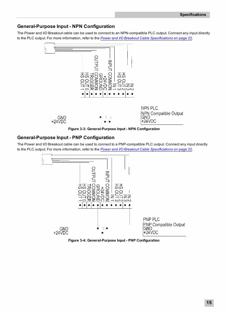
General-Purpose Input - NPN ConfigurationThe Power and I/O Breakout cable can be used to connect to an NPN-compatible PLC output. Connect any input directlyto the PLC output. For more information, refer to the Power and I/O Breakout Cable Specifications on page 22.
Figure 3-3: General-Purpose Input - NPN Configuration
General-Purpose Input - PNP ConfigurationThe Power and I/O Breakout cable can be used to connect to a PNP-compatible PLC output. Connect any input directlyto the PLC output. For more information, refer to the Power and I/O Breakout Cable Specifications on page 22.
Figure 3-4: General-Purpose Input - PNP Configuration
Specifications
15
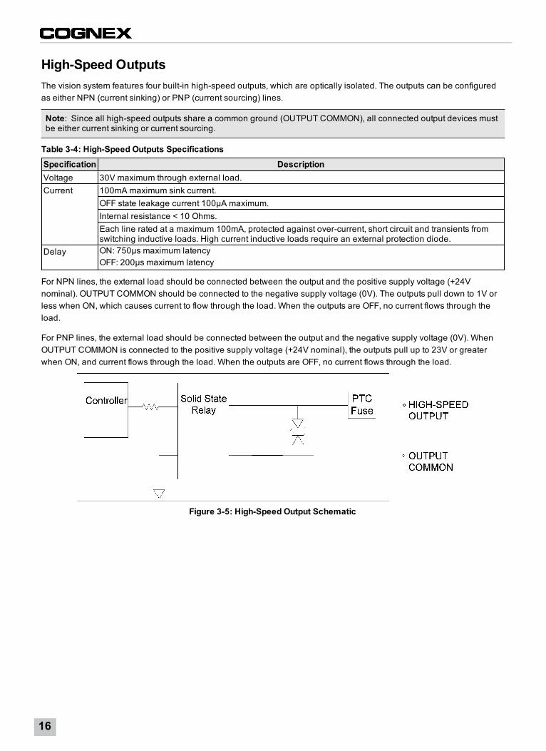
High-Speed OutputsThe vision system features four built-in high-speed outputs, which are optically isolated. The outputs can be configuredas either NPN (current sinking) or PNP (current sourcing) lines.
Note: Since all high-speed outputs share a common ground (OUTPUT COMMON), all connected output devices mustbe either current sinking or current sourcing.
Table 3-4: High-Speed Outputs Specifications
Specification DescriptionVoltage 30V maximum through external load.Current 100mA maximum sink current.
OFF state leakage current 100µA maximum.Internal resistance < 10 Ohms.Each line rated at a maximum 100mA, protected against over-current, short circuit and transients fromswitching inductive loads. High current inductive loads require an external protection diode.
Delay ON: 750µs maximum latencyOFF: 200µs maximum latency
For NPN lines, the external load should be connected between the output and the positive supply voltage (+24Vnominal). OUTPUT COMMON should be connected to the negative supply voltage (0V). The outputs pull down to 1V orless when ON, which causes current to flow through the load. When the outputs are OFF, no current flows through theload.
For PNP lines, the external load should be connected between the output and the negative supply voltage (0V). WhenOUTPUT COMMON is connected to the positive supply voltage (+24V nominal), the outputs pull up to 23V or greaterwhen ON, and current flows through the load. When the outputs are OFF, no current flows through the load.
Figure 3-5: High-Speed Output Schematic
16
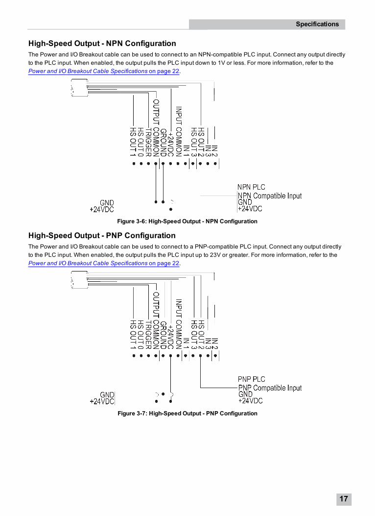
High-Speed Output - NPN ConfigurationThe Power and I/O Breakout cable can be used to connect to an NPN-compatible PLC input. Connect any output directlyto the PLC input. When enabled, the output pulls the PLC input down to 1V or less. For more information, refer to thePower and I/O Breakout Cable Specifications on page 22.
Figure 3-6: High-Speed Output - NPN Configuration
High-Speed Output - PNP ConfigurationThe Power and I/O Breakout cable can be used to connect to a PNP-compatible PLC input. Connect any output directlyto the PLC input. When enabled, the output pulls the PLC input up to 23V or greater. For more information, refer to thePower and I/O Breakout Cable Specifications on page 22.
Figure 3-7: High-Speed Output - PNP Configuration
Specifications
17
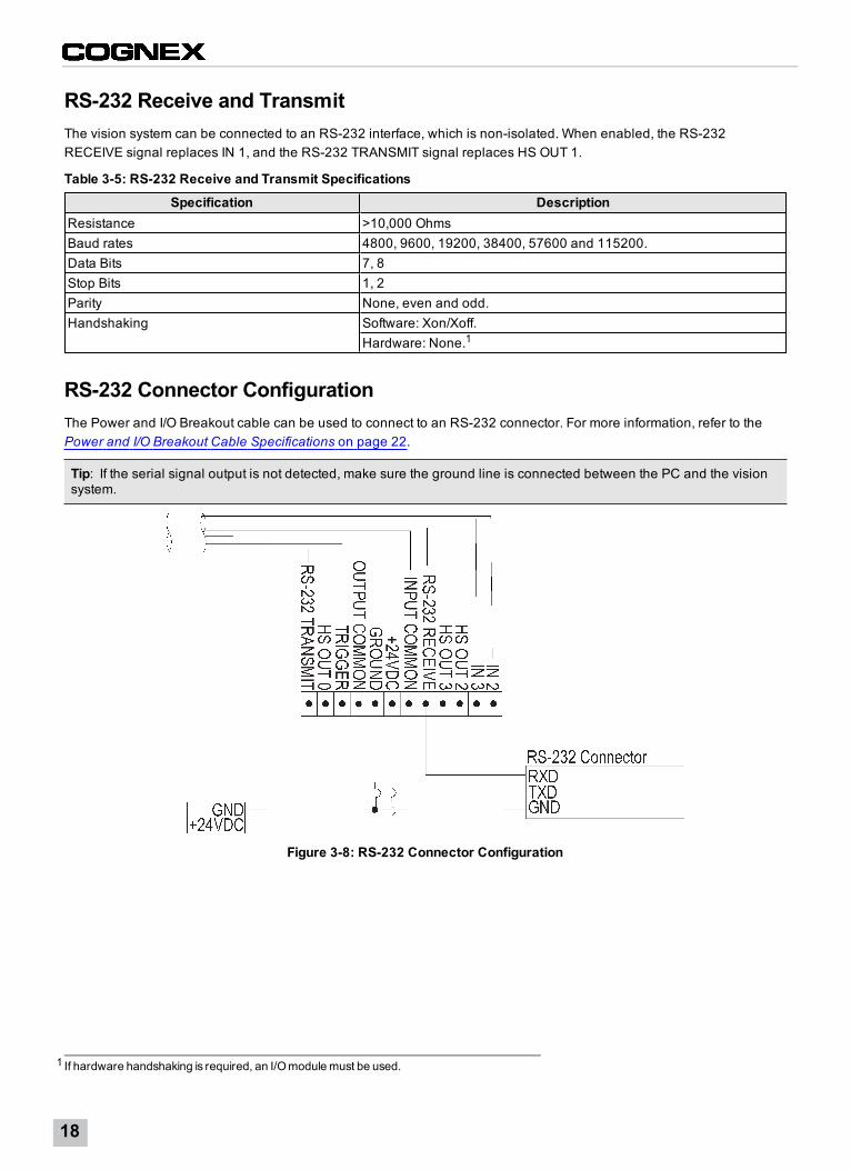
RS-232 Receive and TransmitThe vision system can be connected to an RS-232 interface, which is non-isolated. When enabled, the RS-232RECEIVE signal replaces IN 1, and the RS-232 TRANSMIT signal replaces HS OUT 1.
Table 3-5: RS-232 Receive and Transmit Specifications
Specification DescriptionResistance >10,000 OhmsBaud rates 4800, 9600, 19200, 38400, 57600 and 115200.Data Bits 7, 8Stop Bits 1, 2Parity None, even and odd.Handshaking Software: Xon/Xoff.
Hardware: None.1
RS-232 Connector ConfigurationThe Power and I/O Breakout cable can be used to connect to an RS-232 connector. For more information, refer to thePower and I/O Breakout Cable Specifications on page 22.
Tip: If the serial signal output is not detected, make sure the ground line is connected between the PC and the visionsystem.
Figure 3-8: RS-232 Connector Configuration
1 If hardware handshaking is required, an I/Omodulemust be used.
18
Light ConnectorThe vision system's light connector can be configured to support either continuous illumination mode or strobedillumination mode.
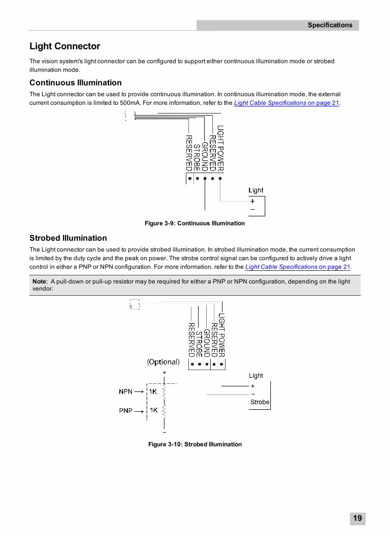
Continuous IlluminationThe Light connector can be used to provide continuous illumination. In continuous illumination mode, the externalcurrent consumption is limited to 500mA. For more information, refer to the Light Cable Specifications on page 21.
Figure 3-9: Continuous Illumination
Strobed IlluminationThe Light connector can be used to provide strobed illumination. In strobed illumination mode, the current consumptionis limited by the duty cycle and the peak on power. The strobe control signal can be configured to actively drive a lightcontrol in either a PNP or NPN configuration. For more information, refer to the Light Cable Specifications on page 21.
Note: A pull-down or pull-up resistor may be required for either a PNP or NPN configuration, depending on the lightvendor.
Figure 3-10: Strobed Illumination
Specifications
19
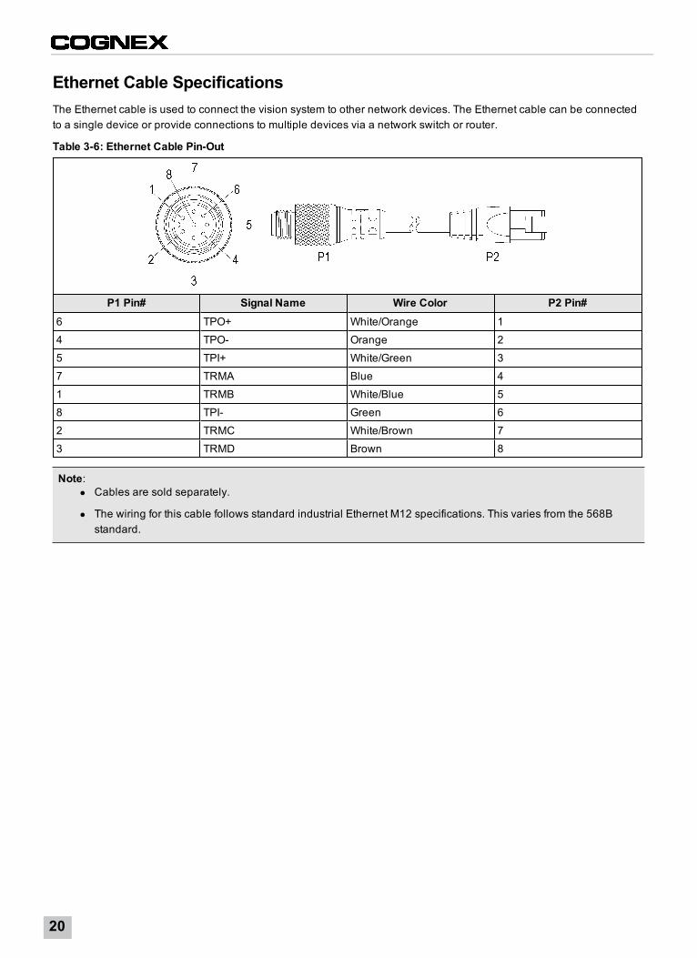
Ethernet Cable SpecificationsThe Ethernet cable is used to connect the vision system to other network devices. The Ethernet cable can be connectedto a single device or provide connections to multiple devices via a network switch or router.
Table 3-6: Ethernet Cable Pin-Out
P1 Pin# Signal Name Wire Color P2 Pin#6 TPO+ White/Orange 1
4 TPO- Orange 2
5 TPI+ White/Green 3
7 TRMA Blue 4
1 TRMB White/Blue 5
8 TPI- Green 6
2 TRMC White/Brown 7
3 TRMD Brown 8
Note:l Cables are sold separately.
l The wiring for this cable follows standard industrial Ethernet M12 specifications. This varies from the 568Bstandard.
20
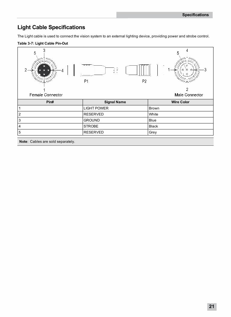
Light Cable SpecificationsThe Light cable is used to connect the vision system to an external lighting device, providing power and strobe control.
Table 3-7: Light Cable Pin-Out
Pin# Signal Name Wire Color1 LIGHT POWER Brown
2 RESERVED White
3 GROUND Blue
4 STROBE Black
5 RESERVED Grey
Note: Cables are sold separately.
Specifications
21
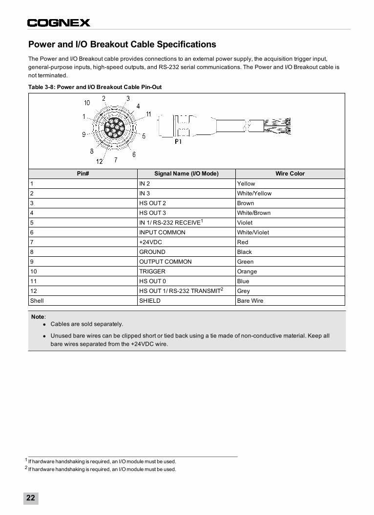
Power and I/O Breakout Cable SpecificationsThe Power and I/O Breakout cable provides connections to an external power supply, the acquisition trigger input,general-purpose inputs, high-speed outputs, and RS-232 serial communications. The Power and I/O Breakout cable isnot terminated.
Table 3-8: Power and I/O Breakout Cable Pin-Out
Pin# Signal Name (I/O Mode) Wire Color1 IN 2 Yellow
2 IN 3 White/Yellow
3 HS OUT 2 Brown
4 HS OUT 3 White/Brown
5 IN 1/ RS-232 RECEIVE1 Violet
6 INPUT COMMON White/Violet
7 +24VDC Red
8 GROUND Black
9 OUTPUT COMMON Green
10 TRIGGER Orange
11 HS OUT 0 Blue
12 HS OUT 1/ RS-232 TRANSMIT2 Grey
Shell SHIELD Bare Wire
Note:l Cables are sold separately.
l Unused bare wires can be clipped short or tied back using a tie made of non-conductive material. Keep allbare wires separated from the +24VDC wire.
1 If hardware handshaking is required, an I/Omodulemust be used.2 If hardware handshaking is required, an I/Omodulemust be used.
22
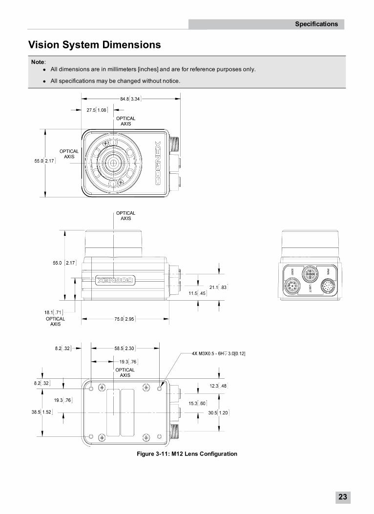
Vision System DimensionsNote:
l All dimensions are in millimeters [inches] and are for reference purposes only.
l All specifications may be changed without notice.
Figure 3-11: M12 Lens Configuration
Specifications
23
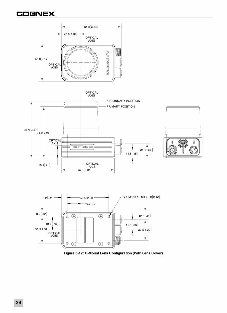
Figure 3-12: C-Mount Lens Configuration (With Lens Cover)
24
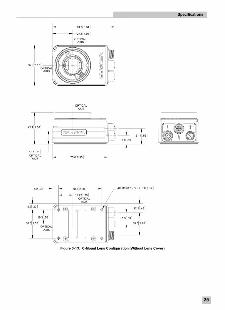
Figure 3-13: C-Mount Lens Configuration (Without Lens Cover)
Specifications
25

26
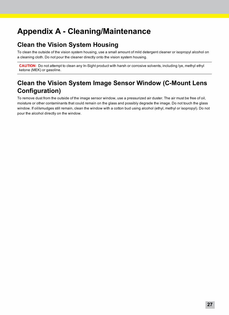
Appendix A - Cleaning/MaintenanceClean the Vision System HousingTo clean the outside of the vision system housing, use a small amount of mild detergent cleaner or isopropyl alcohol ona cleaning cloth. Do not pour the cleaner directly onto the vision system housing.
CAUTION: Do not attempt to clean any In-Sight product with harsh or corrosive solvents, including lye, methyl ethylketone (MEK) or gasoline.
Clean the Vision System Image Sensor Window (C-Mount LensConfiguration)To remove dust from the outside of the image sensor window, use a pressurized air duster. The air must be free of oil,moisture or other contaminants that could remain on the glass and possibly degrade the image. Do not touch the glasswindow. If oil/smudges still remain, clean the window with a cotton bud using alcohol (ethyl, methyl or isopropyl). Do notpour the alcohol directly on the window.
27

28
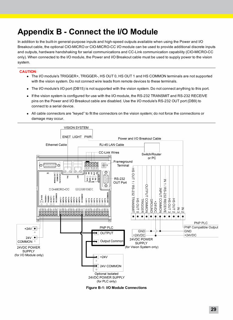
Appendix B - Connect the I/O ModuleIn addition to the built-in general-purpose inputs and high-speed outputs available when using the Power and I/OBreakout cable, the optional CIO-MICRO or CIO-MICRO-CC I/O module can be used to provide additional discrete inputsand outputs, hardware handshaking for serial communications and CC-Link communication capability (CIO-MICRO-CConly). When connected to the I/O module, the Power and I/O Breakout cable must be used to supply power to the visionsystem.
CAUTION:l The I/O module's TRIGGER+, TRIGGER-, HS OUT 0, HS OUT 1 and HS COMMON terminals are not supported
with the vision system. Do not connect wire leads from remote devices to these terminals.
l The I/O module's I/O port (DB15) is not supported with the vision system. Do not connect anything to this port.
l If the vision system is configured for use with the I/O module, the RS-232 TRANSMIT and RS-232 RECEIVEpins on the Power and I/O Breakout cable are disabled. Use the I/O module's RS-232 OUT port (DB9) toconnect to a serial device.
l All cable connectors are “keyed” to fit the connectors on the vision system; do not force the connections ordamage may occur.
Figure B-1: I/O Module Connections
29
Tip: The power supplies for the vision system and I/O module can be combined into a single power supply, providedthe single power supply meets the capacity requirements of the two devices.
1. Connect the I/O Module's power wires.
Note: Never connect the I/O module to a power source other than 24VDC. Any other voltage creates a risk offire or shock and can damage the hardware. Do not connect the 24VDC power source to any terminals otherthan the 24VDC + and – power connectors.
a. Verify that the I/O module's 24VDC power supply is unplugged and not receiving power.
b. Use a screwdriver to loosen the I/O module's power terminals (labeled 24VDC + and –).
c. Insert the 24VDC + and – wires (16 - 22 AWG, solid or stranded wire) from the power supply into the24VDC + and – terminals on the I/O module.
d. Tighten the screw terminals with the screwdriver to secure the wire leads in the terminal block; themaximum torque is 0.1921 Nm (1.7 in-lb).
2. Connect a frame ground wire to the I/O module’s Frame Ground terminal. Connect the other end of the frameground wire to frame ground.
CAUTION: The shield ground connections of the RS-232 port, LAN port, PoE port, I/O port and Frame Groundterminal are internally connected. The system grounding is designed to be at a zero ground potential; this zeroground potential extends through the cable and to peripheral equipment (e.g. a vision system, PLC, etc.). Toensure safe operating conditions, it is strongly recommended that all ground connections are checked toensure that a zero ground potential is met.
3. Connect the I/O module's I/O wires.
Note: The I/O module supports both NPN (current sinking) and PNP (current sourcing) devices. For examplesof NPN configurations, refer to the In-Sight® CIO-MICRO and CIO-MICRO-CC I/O Modules Installation Manual.
a. Determine how I/O devices will be connected to the I/O module’s input and output terminals.
b. Use a screwdriver to loosen the appropriate screw terminals.
c. Insert the input and output wires (16 - 22 AWG, solid or stranded wire) to the input and output terminals.Connect the other end of the input and output wires to the applicable I/O device.
d. Tighten the screw terminals with the screwdriver to secure the wire leads in the terminal block; themaximum torque is 0.1921 Nm (1.7 in-lb).
4. Optionally, connect the I/O module to a CC-Link device.
Note: The CC-Link terminals are only available on the CIO-MICRO-CC I/O module.
a. Determine how CC-Link devices will be connected to the I/O module’s CC-Link terminals. Refer to the In-Sight® CIO-MICRO and CIO-MICRO-CC I/O Modules Installation Manual for CC-Link network wiringexamples.
b. Use a screwdriver to loosen the appropriate screw terminals.
c. Insert the CC-Link wires (using a CC-Link specified cable) to the CC-Link terminals and the other end ofthe cables to the applicable CC-Link devices.
d. To reduce emissions, attach a Steward 28A0640-0A2 ferrite around the CC-Link wire bundle, as close tothe connector as possible.
30
Note: The CC-Link network is daisy-chained and requires a terminal resistor for the first and lastdevices in the chain. Make certain that your connections are correct. Refer to the CC-Link website formore information and specification details.
e. Tighten the screw terminals with the screwdriver to secure the wire leads in the terminal block; themaximum torque is 0.1921 Nm (1.7 in-lb).
5. Optionally, connect the I/O module to a serial device.a. Plug an RS-232 serial cable (DB9 connector) into the I/O module’s RS-232 OUT port.
b. Tighten the connector screws to secure it to the I/O module.
c. Connect the other end of the RS-232 serial cable to the serial device.
6. Connect to an Ethernet network.a. Plug a LAN cable (RJ-45 connector) into the I/O module’s LAN port.
b. Connect the other end of the LAN cable to a switch/router or PC, as applicable.
7. Connect the vision system's Ethernet cable.a. Plug the Ethernet cable’s keyed M12 connector into the vision system’s ENET connector.
b. Plug the Ethernet cable’s RJ-45 connector into the I/O module’s PoE port.
CAUTION: The I/O module’s PoE port provides Ethernet connectivity to the vision system. Connectingthird-party devices to the I/O module's PoE port could damage the I/O module.
8. Connect the vision system's Power and I/O Breakout cable.
Note: Unused bare wires can be clipped short or tied back using a tie made of non-conductive material.Keepall bare wires separated from the +24VDC wire.
a. Verify that the vision system's 24VDC power supply is unplugged and not receiving power.
b. Optionally connect the I/O wires to an appropriate device (for example, a PLC). Refer to Power and I/OBreakout Cable Specifications on page 22 for wiring details.
c. Attach the Power and I/O Breakout cable's +24VDC (Red wire) and GROUND (Black wire) to thecorresponding terminals on the power supply. Refer to Power and I/O Breakout Cable Specifications onpage 22 for wiring details.
CAUTION: Never connect voltages other than 24VDC. Always observe the polarity shown.
d. Connect the Power and I/O Breakout cable's M12 connector to the vision system's PWR connector.
e. Restore power to the vision system’s 24VDC power supply and turn it on if necessary.
9. Restore power to the I/O module’s 24VDC power supply and turn it on if necessary.
Appendix B - Connect the I/O Module
31

32


P/N 597-0138-01 Rev. CPrinted in the USA