Embed Size (px)
Citation preview
In-Sight® 5000 SeriesVision SystemReference Guide
02/21/2017Version: 5.4.0.6

Legal NoticesThe software described in this document is furnished under license, and may be used or copied only in accordance withthe terms of such license and with the inclusion of the copyright notice shown on this page. Neither the software, thisdocument, nor any copies thereof may be provided to, or otherwise made available to, anyone other than the licensee.Title to, and ownership of, this software remains with Cognex Corporation or its licensor. Cognex Corporation assumesno responsibility for the use or reliability of its software on equipment that is not supplied by Cognex Corporation.Cognex Corporation makes no warranties, either express or implied, regarding the described software, itsmerchantability, non-infringement or its fitness for any particular purpose.
The information in this document is subject to change without notice and should not be construed as a commitment byCognex Corporation. Cognex Corporation is not responsible for any errors that may be present in either this document orthe associated software.
Companies, names, and data used in examples herein are fictitious unless otherwise noted. No part of this documentmay be reproduced or transmitted in any form or by any means, electronic or mechanical, for any purpose, nortransferred to any other media or language without the written permission of Cognex Corporation.
Copyright © 2003 - 2016. Cognex Corporation. All Rights Reserved.
Portions of the hardware and software provided by Cognex may be covered by one or more U.S. and foreign patents, aswell as pending U.S. and foreign patents listed on the Cognex web site at: http://www.cognex.com/patents.
The following are registered trademarks of Cognex Corporation:
Cognex, 2DMAX, Advantage, AlignPlus, Assemblyplus, Check it with Checker, Checker, Cognex Vision for Industry,Cognex VSOC, CVL, DataMan, DisplayInspect, DVT, EasyBuilder, Hotbars, IDMax, In-Sight, Laser Killer, MVS-8000,OmniView, PatFind, PatFlex, PatInspect, PatMax, PatQuick, SensorView, SmartView, SmartAdvisor, SmartLearn,UltraLight, Vision Solutions, VisionPro, VisionView
The following are trademarks of Cognex Corporation:
The Cognex logo, 1DMax, 3D-Locate, 3DMax, BGAII, CheckPoint, Cognex VSoC, CVC-1000, FFD, iLearn, In-Sight(design insignia with cross-hairs), In-Sight 2000, InspectEdge, Inspection Designer, MVS, NotchMax, OCRMax,PatMax RedLine, ProofRead, SmartSync, ProfilePlus, SmartDisplay, SmartSystem, SMD4, VisiFlex, Xpand
Other product and company trademarks identified herein are the trademarks of their respective owners.
2
Legal Notices
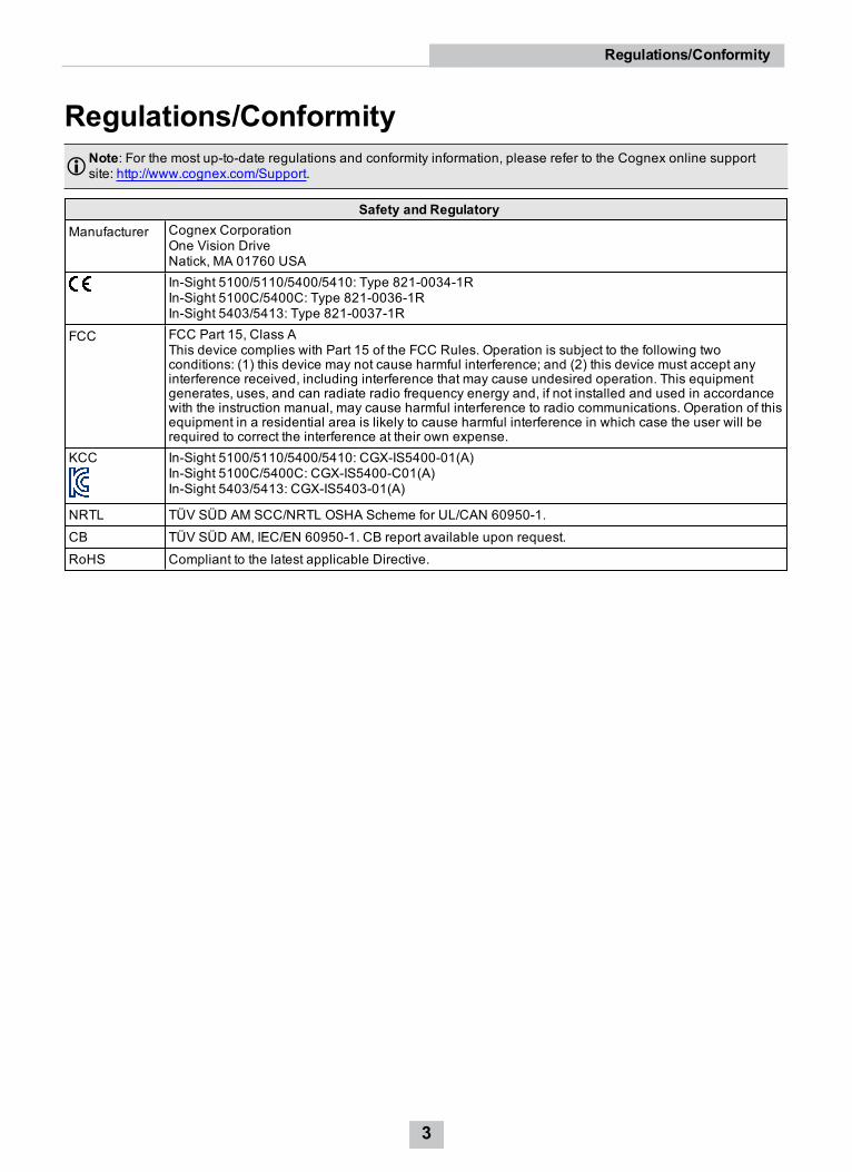
Regulations/ConformityNote: For the most up-to-date regulations and conformity information, please refer to the Cognex online supportsite: http://www.cognex.com/Support.
Safety and RegulatoryManufacturer Cognex Corporation
One Vision DriveNatick, MA 01760 USAIn-Sight 5100/5110/5400/5410: Type 821-0034-1RIn-Sight 5100C/5400C: Type 821-0036-1RIn-Sight 5403/5413: Type 821-0037-1R
FCC FCC Part 15, Class AThis device complies with Part 15 of the FCC Rules. Operation is subject to the following twoconditions: (1) this device may not cause harmful interference; and (2) this device must accept anyinterference received, including interference that may cause undesired operation. This equipmentgenerates, uses, and can radiate radio frequency energy and, if not installed and used in accordancewith the instruction manual, may cause harmful interference to radio communications. Operation of thisequipment in a residential area is likely to cause harmful interference in which case the user will berequired to correct the interference at their own expense.
KCC In-Sight 5100/5110/5400/5410: CGX-IS5400-01(A)In-Sight 5100C/5400C: CGX-IS5400-C01(A)In-Sight 5403/5413: CGX-IS5403-01(A)
NRTL TÜV SÜD AM SCC/NRTL OSHA Scheme for UL/CAN 60950-1.
CB TÜV SÜD AM, IEC/EN 60950-1. CB report available upon request.
RoHS Compliant to the latest applicable Directive.
3
Regulations/Conformity
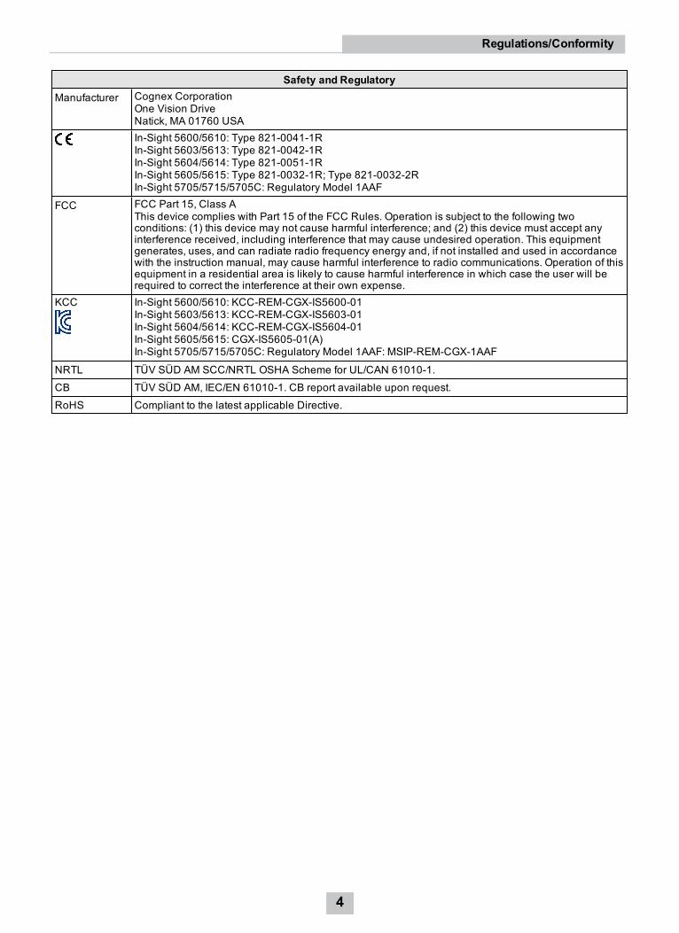
Safety and RegulatoryManufacturer Cognex Corporation
One Vision DriveNatick, MA 01760 USAIn-Sight 5600/5610: Type 821-0041-1RIn-Sight 5603/5613: Type 821-0042-1RIn-Sight 5604/5614: Type 821-0051-1RIn-Sight 5605/5615: Type 821-0032-1R; Type 821-0032-2RIn-Sight 5705/5715/5705C: Regulatory Model 1AAF
FCC FCC Part 15, Class AThis device complies with Part 15 of the FCC Rules. Operation is subject to the following twoconditions: (1) this device may not cause harmful interference; and (2) this device must accept anyinterference received, including interference that may cause undesired operation. This equipmentgenerates, uses, and can radiate radio frequency energy and, if not installed and used in accordancewith the instruction manual, may cause harmful interference to radio communications. Operation of thisequipment in a residential area is likely to cause harmful interference in which case the user will berequired to correct the interference at their own expense.
KCC In-Sight 5600/5610: KCC-REM-CGX-IS5600-01In-Sight 5603/5613: KCC-REM-CGX-IS5603-01In-Sight 5604/5614: KCC-REM-CGX-IS5604-01In-Sight 5605/5615: CGX-IS5605-01(A)In-Sight 5705/5715/5705C: Regulatory Model 1AAF: MSIP-REM-CGX-1AAF
NRTL TÜV SÜD AM SCC/NRTL OSHA Scheme for UL/CAN 61010-1.
CB TÜV SÜD AM, IEC/EN 61010-1. CB report available upon request.
RoHS Compliant to the latest applicable Directive.
4
Regulations/Conformity
PrecautionsObserve these precautions when installing the Cognex product, to reduce the risk of injury or equipment damage:
l In-Sight 5000 series vision systems are intended to be supplied by a UL or NRTL listed power supply with a24VDC output rated for at least 600 mA continuous and a maximum short circuit current rating of less than 8A anda maximum power rating of less than 100VA and marked Class 2 or Limited Power Source (LPS). Any othervoltage creates a risk of fire or shock and can damage the components. Applicable national and local wiringstandards and rules must be followed.
l Do not install Cognex products where they are directly exposed to environmental hazards such as excessiveheat, dust, moisture, humidity, impact, vibration, corrosive substances, flammable substances, or static electricity.
l To reduce the risk of damage or malfunction due to over-voltage, line noise, electrostatic discharge (ESD), powersurges, or other irregularities in the power supply, route all cables and wires away from high-voltage powersources.
l The housing of the vision system is internally connected to the system ground wire (pin 8 of the Breakout cable).Therefore, if the mounting surface of the vision system is at a non-zero ground potential, it is stronglyrecommended that the vision system be mounted on an isolated or non-conductive mount.
l Do not expose the image sensor to laser light; image sensors can be damaged by direct, or reflected, laser light.If your application requires the use of laser light that may strike the image sensor, a lens filter at thecorresponding laser's wavelength is recommended. Contact your local integrator or application engineer forsuggestions.
l The In-Sight vision system does not contain user-serviceable parts. Do not make electrical or mechanicalmodifications to In-Sight vision system components. Unauthorized modifications may void your warranty.
l Changes or modifications not expressly approved by the party responsible for regulatory compliance could voidthe user’s authority to operate the equipment.
l Service loops should be included with all cable connections.
l Cable shielding can be degraded or cables can be damaged or wear out more quickly if a service loop or bendradius is tighter than 10X the cable diameter. The bend radius must begin at least six inches from the connector.
l Class A Equipment (broadcasting and communication equipment for office work): Seller and user shall benotified that this equipment is suitable for electromagnetic equipment for office work (Class A) and can be usedoutside the home.
l This device should be used in accordance with the instructions in this manual.
5
Precautions
Table of ContentsLegal Notices 2Regulations/Conformity 3Precautions 5Table of Contents 6Introduction 7Support 7Standard Components 7Accessories 8Cables 8I/OModules 10
Installation 12Connectors and Indicators 12Install the Lens 13Connect the Ethernet Cable 13Connect the Breakout Cable 14
Specifications 155100, 5100C, 5400C, 5403 and 5400 Vision System Specifications 155603, 5600 and 5605 Vision System Specifications 175604 Line Scan Vision System Specifications 195705 and 5705C Vision System Specifications 21I/O Specifications 23Acquisition Trigger Input 23Encoder Inputs (In-Sight 5604Only) 24High-SpeedOutputs 255100 and 5400 Series Vision System Ethernet Cable Specifications 275600 and 5700 Series Vision System Ethernet Cable Specifications 28Breakout Cable Specifications 29I/OModule Cable Specifications 30
Dimensional Drawings 315100, 5100C, 5400, 5400C and 5403 Vision System (With Lens Cover) 315100, 5100C, 5400, 5400C and 5403 Vision System (Without Lens Cover) 325600 and 5603 Vision System (With Lens Cover) 335600 and 5603 Vision System (Without Lens Cover) 345604, 5605, 5705, and 5705C Vision System (With Lens Cover) 355604, 5605, 5705, and 5705C Vision System (Without Lens Cover) 36
Cleaning/Maintenance 37Clean the Vision System Housing 37Clean the Vision System Image SensorWindow 37Clean the Vision System Lens Cover 37
6
Table of Contents
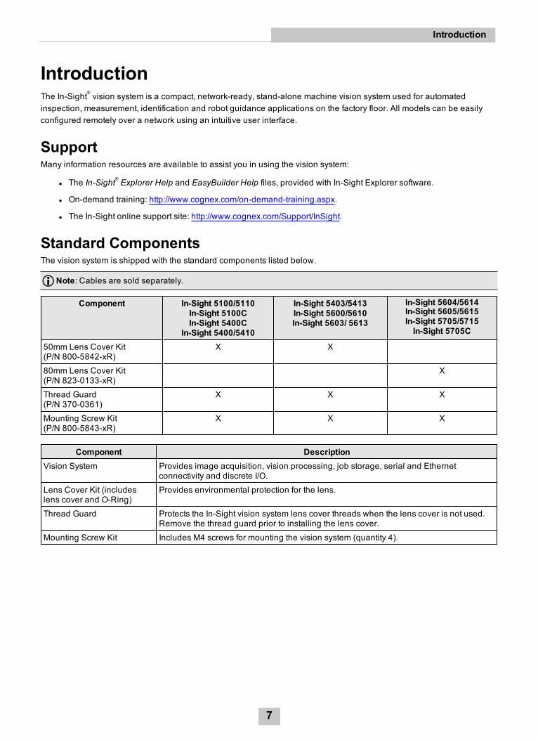
IntroductionThe In-Sight® vision system is a compact, network-ready, stand-alone machine vision system used for automatedinspection, measurement, identification and robot guidance applications on the factory floor. All models can be easilyconfigured remotely over a network using an intuitive user interface.
SupportMany information resources are available to assist you in using the vision system:
l The In-Sight® Explorer Help and EasyBuilder Help files, provided with In-Sight Explorer software.
l On-demand training: http://www.cognex.com/on-demand-training.aspx.
l The In-Sight online support site: http://www.cognex.com/Support/InSight.
Standard ComponentsThe vision system is shipped with the standard components listed below.
Note: Cables are sold separately.
Component In-Sight 5100/5110In-Sight 5100CIn-Sight 5400C
In-Sight 5400/5410
In-Sight 5403/5413In-Sight 5600/5610In-Sight 5603/ 5613
In-Sight 5604/5614In-Sight 5605/5615In-Sight 5705/5715In-Sight 5705C
50mm Lens Cover Kit(P/N 800-5842-xR)
X X
80mm Lens Cover Kit(P/N 823-0133-xR)
X
Thread Guard(P/N 370-0361)
X X X
Mounting Screw Kit(P/N 800-5843-xR)
X X X
Component DescriptionVision System Provides image acquisition, vision processing, job storage, serial and Ethernet
connectivity and discrete I/O.
Lens Cover Kit (includeslens cover and O-Ring)
Provides environmental protection for the lens.
Thread Guard Protects the In-Sight vision system lens cover threads when the lens cover is not used.Remove the thread guard prior to installing the lens cover.
Mounting Screw Kit Includes M4 screws for mounting the vision system (quantity 4).
7
Introduction
AccessoriesThe following components can be purchased separately. For a complete list of options and accessories, contact yourlocal Cognex sales representative.
CablesNote: Cables are sold separately.
CAUTION: All cable connectors are “keyed” to fit the connectors on the vision system; do not force the connectionsor damage may occur.
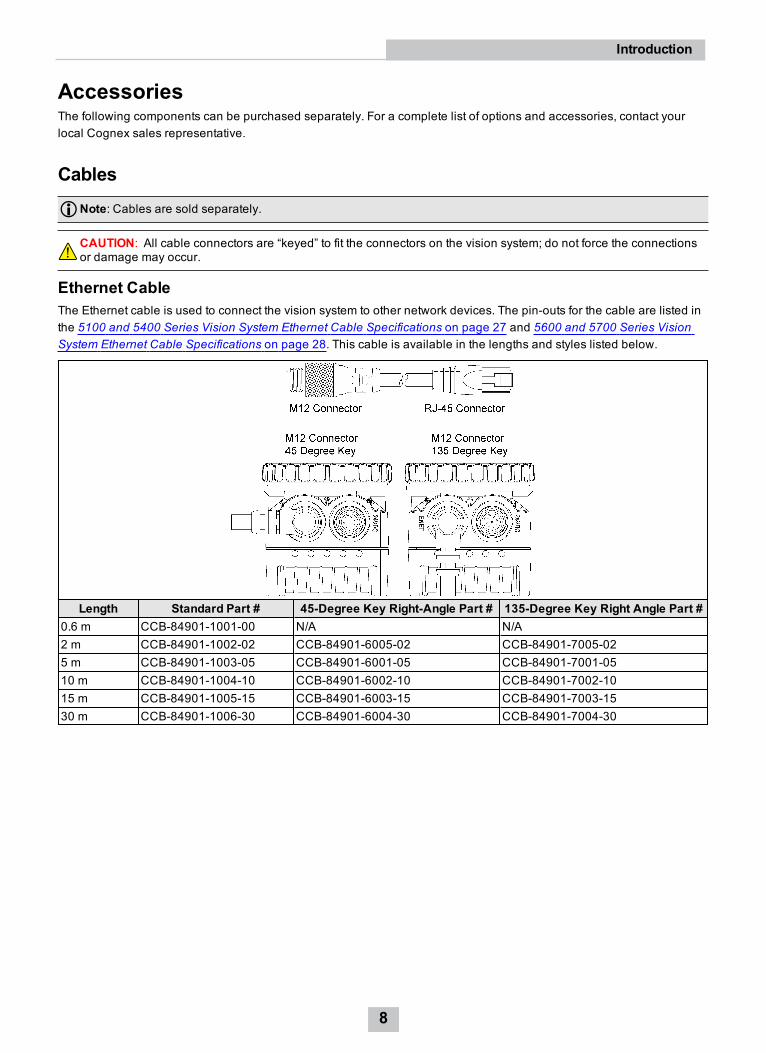
Ethernet CableThe Ethernet cable is used to connect the vision system to other network devices. The pin-outs for the cable are listed inthe 5100 and 5400 Series Vision System Ethernet Cable Specifications on page 27 and 5600 and 5700 Series VisionSystem Ethernet Cable Specifications on page 28. This cable is available in the lengths and styles listed below.
Length Standard Part # 45-Degree Key Right-Angle Part # 135-Degree Key Right Angle Part #0.6 m CCB-84901-1001-00 N/A N/A2 m CCB-84901-1002-02 CCB-84901-6005-02 CCB-84901-7005-025 m CCB-84901-1003-05 CCB-84901-6001-05 CCB-84901-7001-0510 m CCB-84901-1004-10 CCB-84901-6002-10 CCB-84901-7002-1015 m CCB-84901-1005-15 CCB-84901-6003-15 CCB-84901-7003-1530 m CCB-84901-1006-30 CCB-84901-6004-30 CCB-84901-7004-30
8
Introduction
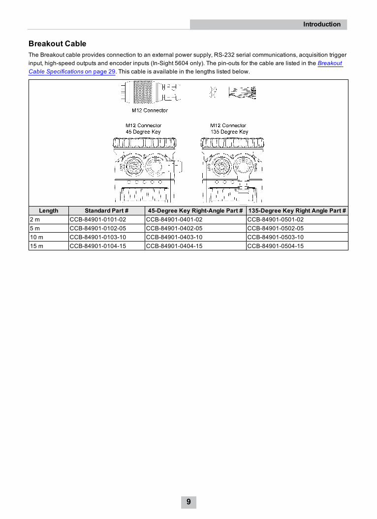
Breakout CableThe Breakout cable provides connection to an external power supply, RS-232 serial communications, acquisition triggerinput, high-speed outputs and encoder inputs (In-Sight 5604 only). The pin-outs for the cable are listed in the BreakoutCable Specifications on page 29. This cable is available in the lengths listed below.
Length Standard Part # 45-Degree Key Right-Angle Part # 135-Degree Key Right Angle Part #2 m CCB-84901-0101-02 CCB-84901-0401-02 CCB-84901-0501-025 m CCB-84901-0102-05 CCB-84901-0402-05 CCB-84901-0502-0510 m CCB-84901-0103-10 CCB-84901-0403-10 CCB-84901-0503-1015 m CCB-84901-0104-15 CCB-84901-0404-15 CCB-84901-0504-15
9
Introduction
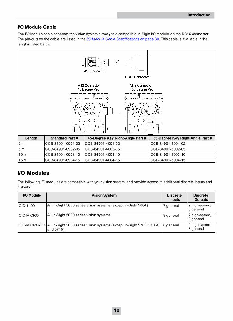
I/O Module CableThe I/O Module cable connects the vision system directly to a compatible In-Sight I/O module via the DB15 connector.The pin-outs for the cable are listed in the I/O Module Cable Specifications on page 30. This cable is available in thelengths listed below.
Length Standard Part # 45-Degree Key Right-Angle Part # 35-Degree Key Right-Angle Part #2 m CCB-84901-0901-02 CCB-84901-4001-02 CCB-84901-5001-025 m CCB-84901-0902-05 CCB-84901-4002-05 CCB-84901-5002-0510 m CCB-84901-0903-10 CCB-84901-4003-10 CCB-84901-5003-1015 m CCB-84901-0904-15 CCB-84901-4004-15 CCB-84901-5004-15
I/O ModulesThe following I/O modules are compatible with your vision system, and provide access to additional discrete inputs andoutputs.
I/O Module Vision System DiscreteInputs
DiscreteOutputs
CIO-1400 All In-Sight 5000 series vision systems (except In-Sight 5604) 7 general 2 high-speed,6 general
CIO-MICRO All In-Sight 5000 series vision systems 8 general 2 high-speed,8 general
CIO-MICRO-CC All In-Sight 5000 series vision systems (except In-Sight 5705, 5705Cand 5715)
8 general 2 high-speed,8 general
10
Introduction
Note:l The CIO-MICRO I/O module only supports In-Sight 5700 series vision systems with firmware version 5.3.0and higher.
l The CIO-MICRO and CIO-MICRO-CC I/O modules do not support 1000 BaseT pass-through operation. If1000 BaseT operation is required when using the In-Sight 5600 series or In-Sight 5700 series visionsystem, you must connect a LAN cable from a Gigabit Ethernet switch to the I/O module’s LAN port andconnect the vision system’s Ethernet cable to the Gigabit Ethernet switch.
l The CIO-MICRO & CIO-MICRO-CC I/O modules support In-Sight 5100 series and 5400 series visionsystems with 128MB non-volatile flash memory or higher and support all In-Sight 5600 series visionsystems.
l The CIO-MICRO-CC I/O module also adds CC-link networking capability. Refer to the In-Sight® CIO-MICROand CIO-MICRO-CC I/O Module Installation Manual for detailed connection information.
11
Introduction

InstallationThis section describes the connection of the vision system to its standard components and accessories. For a completelist of options and accessories, contact your Cognex sales representative.
Note:l Cables are sold separately.
l If any of the standard components appear to be missing or damaged, immediately contact your CognexAuthorized Service Provider (ASP) or Cognex Technical Support.
CAUTION: All cable connectors are “keyed” to fit the connectors on the vision system; do not force the connectionsor damage may occur.
Connectors and Indicators
Connector/Indicator Function24VDC Connector Connects the Breakout cable, which provides connections to an external power
supply, the acquisition trigger input, high-speed outputs and RS-232 serialcommunications. For more information, refer to Breakout Cable Specifications onpage 29. Alternately, this connector is used to attach the I/O Module cable to anoptional In-Sight I/O module, which adds general-purpose discrete I/O and lightcontrol functionality. For more information, refer to the I/O Module CableSpecifications on page 30.
User 1 LED Green when active. User-configurable within the In-Sight Explorer Discrete OutputSettings dialog, using Discrete Output Line 4 (Line 10 for all I/O modules, exceptthe CIO-1400, which uses Line 9).
User 0 LED Red when active. User-configurable within the In-Sight Explorer Discrete OutputSettings dialog, using Discrete Output Line 5 (Line 11 for all I/O modules, exceptthe CIO-1400, which uses Line 10).
Power LED Green when power is applied.
Network Traffic LED Flashes green while transmitting and receiving data.
Network Status LED Green when a network connection is detected.
ENET Connector Connects the vision system to a network. The ENET connector provides theEthernet connection to external network devices. For more information, refer to the5100 and 5400 Series Vision System Ethernet Cable Specifications on page 27and 5600 and 5700 Series Vision System Ethernet Cable Specifications onpage 28.
12
Installation
Note:l For the In-Sight 5100 and 5400 series, when the vision system is powered up, User 0 LED and User 1 LEDboth momentarily turn on. Then, User 0 LED turns off and User 1 LED stays on. Next, User 0 LED turns onand User 1 LED turns off. Finally, both LEDs momentarily turn on and then turn off.
l For the In-Sight 5600 series and In-Sight 5700 series, when the vision system is powered up, User 0 LEDand User 1 LED both momentarily turn on. Then, User 1 LED turns off and User 0 LED stays on. Next, User1 LED turns on and User 0 LED turns off. Finally, both LEDs momentarily turn on and then turn off.
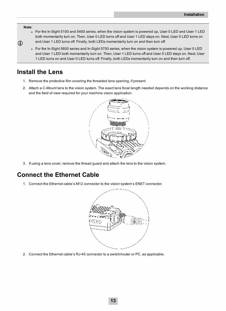
Install the Lens1. Remove the protective film covering the threaded lens opening, if present.
2. Attach a C-Mount lens to the vision system. The exact lens focal length needed depends on the working distanceand the field of view required for your machine vision application.
3. If using a lens cover, remove the thread guard and attach the lens to the vision system.
Connect the Ethernet Cable1. Connect the Ethernet cable’s M12 connector to the vision system’s ENET connector.
2. Connect the Ethernet cable’s RJ-45 connector to a switch/router or PC, as applicable.
13
Installation
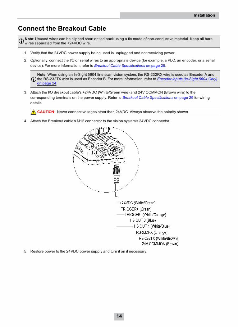
Connect the Breakout CableNote: Unused wires can be clipped short or tied back using a tie made of non-conductive material. Keep all barewires separated from the +24VDC wire.
1. Verify that the 24VDC power supply being used is unplugged and not receiving power.
2. Optionally, connect the I/O or serial wires to an appropriate device (for example, a PLC, an encoder, or a serialdevice). For more information, refer to Breakout Cable Specifications on page 29.
Note: When using an In-Sight 5604 line scan vision system, the RS-232RX wire is used as Encoder A andthe RS-232TX wire is used as Encoder B. For more information, refer to Encoder Inputs (In-Sight 5604 Only)on page 24.
3. Attach the I/O Breakout cable's +24VDC (White/Green wire) and 24V COMMON (Brown wire) to thecorresponding terminals on the power supply. Refer to Breakout Cable Specifications on page 29 for wiringdetails.
CAUTION: Never connect voltages other than 24VDC. Always observe the polarity shown.
4. Attach the Breakout cable's M12 connector to the vision system's 24VDC connector.
5. Restore power to the 24VDC power supply and turn it on if necessary.
14
Installation
SpecificationsThe following sections list general specifications for the In-Sight 5000 series vision systems.
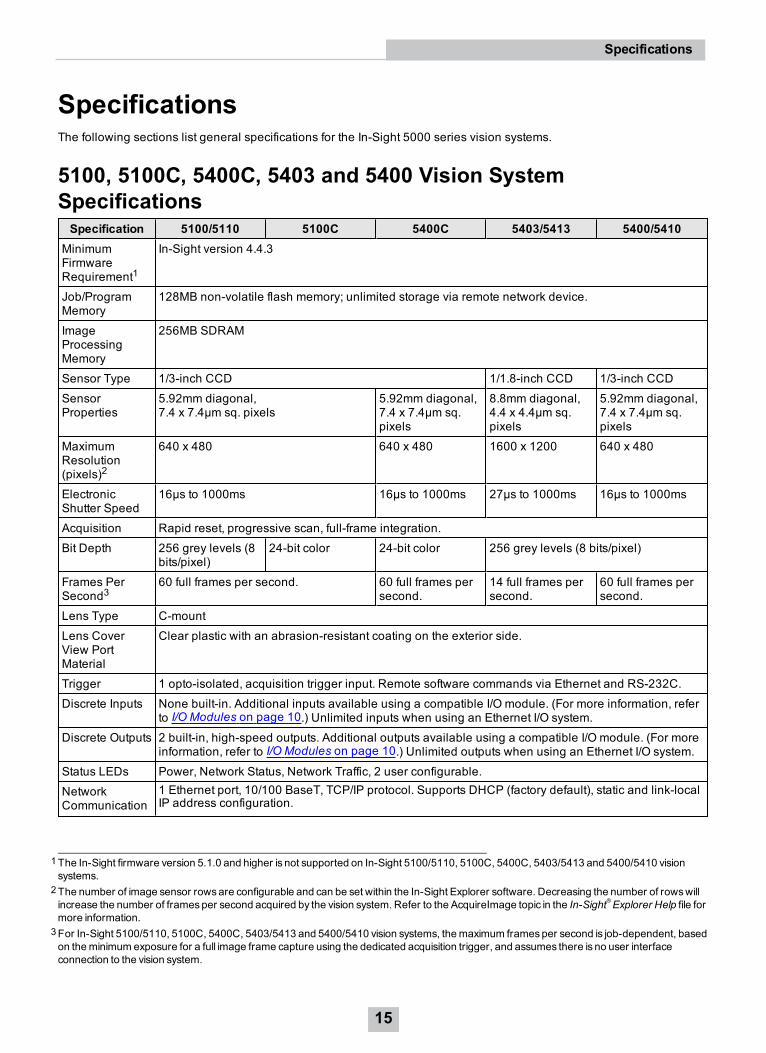
5100, 5100C, 5400C, 5403 and 5400 Vision SystemSpecificationsSpecification 5100/5110 5100C 5400C 5403/5413 5400/5410
MinimumFirmwareRequirement1
In-Sight version 4.4.3
Job/ProgramMemory
128MB non-volatile flash memory; unlimited storage via remote network device.
ImageProcessingMemory
256MB SDRAM
Sensor Type 1/3-inch CCD 1/1.8-inch CCD 1/3-inch CCD
SensorProperties
5.92mm diagonal,7.4 x 7.4µm sq. pixels
5.92mm diagonal,7.4 x 7.4µm sq.pixels
8.8mm diagonal,4.4 x 4.4µm sq.pixels
5.92mm diagonal,7.4 x 7.4µm sq.pixels
MaximumResolution(pixels)2
640 x 480 640 x 480 1600 x 1200 640 x 480
ElectronicShutter Speed
16µs to 1000ms 16µs to 1000ms 27µs to 1000ms 16µs to 1000ms
Acquisition Rapid reset, progressive scan, full-frame integration.
Bit Depth 256 grey levels (8bits/pixel)
24-bit color 24-bit color 256 grey levels (8 bits/pixel)
Frames PerSecond3
60 full frames per second. 60 full frames persecond.
14 full frames persecond.
60 full frames persecond.
Lens Type C-mount
Lens CoverView PortMaterial
Clear plastic with an abrasion-resistant coating on the exterior side.
Trigger 1 opto-isolated, acquisition trigger input. Remote software commands via Ethernet and RS-232C.
Discrete Inputs None built-in. Additional inputs available using a compatible I/O module. (For more information, referto I/O Modules on page 10.) Unlimited inputs when using an Ethernet I/O system.
Discrete Outputs 2 built-in, high-speed outputs. Additional outputs available using a compatible I/O module. (For moreinformation, refer to I/O Modules on page 10.) Unlimited outputs when using an Ethernet I/O system.
Status LEDs Power, Network Status, Network Traffic, 2 user configurable.
NetworkCommunication
1 Ethernet port, 10/100 BaseT, TCP/IP protocol. Supports DHCP (factory default), static and link-localIP address configuration.
1The In-Sight firmware version 5.1.0 and higher is not supported on In-Sight 5100/5110, 5100C, 5400C, 5403/5413 and 5400/5410 visionsystems.
2The number of image sensor rowsare configurable and can be set within the In-Sight Explorer software. Decreasing the number of rowswillincrease the number of framesper second acquired by the vision system. Refer to the AcquireImage topic in the In-Sight®Explorer Help file formore information.
3For In-Sight 5100/5110, 5100C, 5400C, 5403/5413 and 5400/5410 vision systems, themaximum framesper second is job-dependent, basedon theminimum exposure for a full image frame capture using the dedicated acquisition trigger, and assumes there is no user interfaceconnection to the vision system.
15
Specifications
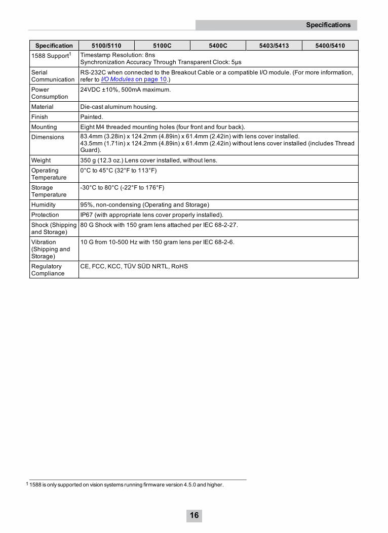
Specification 5100/5110 5100C 5400C 5403/5413 5400/54101588 Support1 Timestamp Resolution: 8ns
Synchronization Accuracy Through Transparent Clock: 5µs
SerialCommunication
RS-232C when connected to the Breakout Cable or a compatible I/O module. (For more information,refer to I/O Modules on page 10.)
PowerConsumption
24VDC ±10%, 500mA maximum.
Material Die-cast aluminum housing.
Finish Painted.
Mounting Eight M4 threaded mounting holes (four front and four back).
Dimensions 83.4mm (3.28in) x 124.2mm (4.89in) x 61.4mm (2.42in) with lens cover installed.43.5mm (1.71in) x 124.2mm (4.89in) x 61.4mm (2.42in) without lens cover installed (includes ThreadGuard).
Weight 350 g (12.3 oz.) Lens cover installed, without lens.
OperatingTemperature
0°C to 45°C (32°F to 113°F)
StorageTemperature
-30°C to 80°C (-22°F to 176°F)
Humidity 95%, non-condensing (Operating and Storage)
Protection IP67 (with appropriate lens cover properly installed).
Shock (Shippingand Storage)
80 G Shock with 150 gram lens attached per IEC 68-2-27.
Vibration(Shipping andStorage)
10 G from 10-500 Hz with 150 gram lens per IEC 68-2-6.
RegulatoryCompliance
CE, FCC, KCC, TÜV SÜD NRTL, RoHS
11588 is only supported on vision systems running firmware version 4.5.0 and higher.
16
Specifications
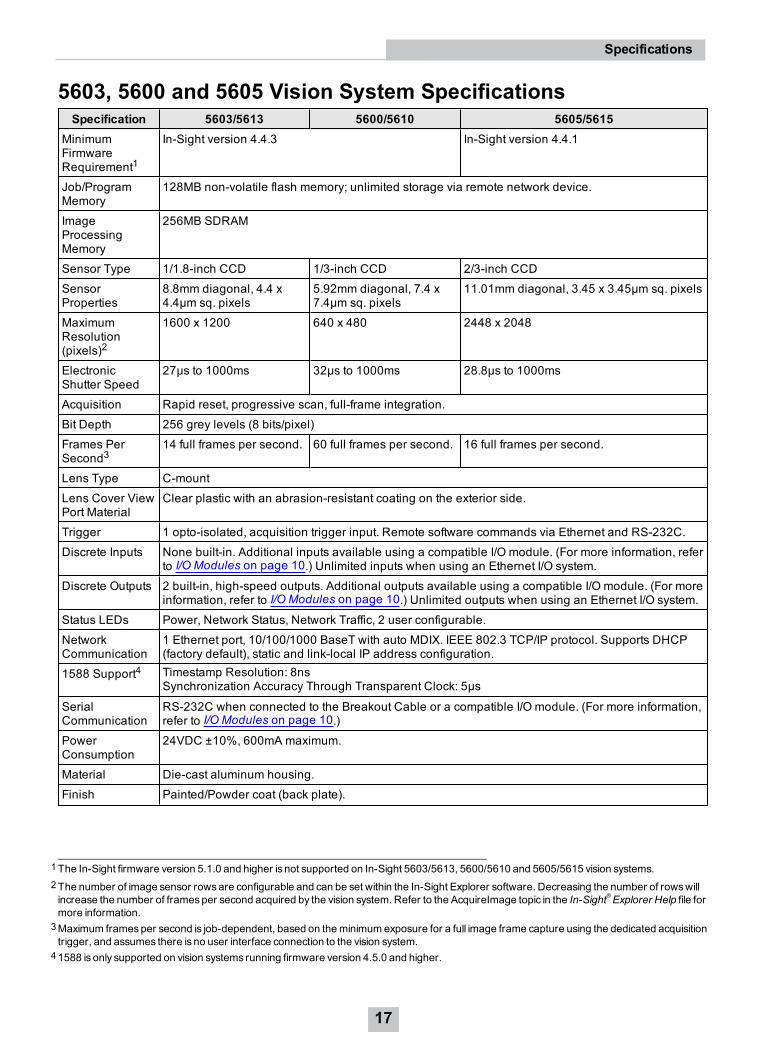
5603, 5600 and 5605 Vision System SpecificationsSpecification 5603/5613 5600/5610 5605/5615
MinimumFirmwareRequirement1
In-Sight version 4.4.3 In-Sight version 4.4.1
Job/ProgramMemory
128MB non-volatile flash memory; unlimited storage via remote network device.
ImageProcessingMemory
256MB SDRAM
Sensor Type 1/1.8-inch CCD 1/3-inch CCD 2/3-inch CCD
SensorProperties
8.8mm diagonal, 4.4 x4.4µm sq. pixels
5.92mm diagonal, 7.4 x7.4µm sq. pixels
11.01mm diagonal, 3.45 x 3.45µm sq. pixels
MaximumResolution(pixels)2
1600 x 1200 640 x 480 2448 x 2048
ElectronicShutter Speed
27µs to 1000ms 32µs to 1000ms 28.8µs to 1000ms
Acquisition Rapid reset, progressive scan, full-frame integration.
Bit Depth 256 grey levels (8 bits/pixel)
Frames PerSecond3
14 full frames per second. 60 full frames per second. 16 full frames per second.
Lens Type C-mount
Lens Cover ViewPort Material
Clear plastic with an abrasion-resistant coating on the exterior side.
Trigger 1 opto-isolated, acquisition trigger input. Remote software commands via Ethernet and RS-232C.
Discrete Inputs None built-in. Additional inputs available using a compatible I/O module. (For more information, referto I/O Modules on page 10.) Unlimited inputs when using an Ethernet I/O system.
Discrete Outputs 2 built-in, high-speed outputs. Additional outputs available using a compatible I/O module. (For moreinformation, refer to I/O Modules on page 10.) Unlimited outputs when using an Ethernet I/O system.
Status LEDs Power, Network Status, Network Traffic, 2 user configurable.
NetworkCommunication
1 Ethernet port, 10/100/1000 BaseT with auto MDIX. IEEE 802.3 TCP/IP protocol. Supports DHCP(factory default), static and link-local IP address configuration.
1588 Support4 Timestamp Resolution: 8nsSynchronization Accuracy Through Transparent Clock: 5µs
SerialCommunication
RS-232C when connected to the Breakout Cable or a compatible I/O module. (For more information,refer to I/O Modules on page 10.)
PowerConsumption
24VDC ±10%, 600mA maximum.
Material Die-cast aluminum housing.
Finish Painted/Powder coat (back plate).
1The In-Sight firmware version 5.1.0 and higher is not supported on In-Sight 5603/5613, 5600/5610 and 5605/5615 vision systems.2The number of image sensor rowsare configurable and can be set within the In-Sight Explorer software. Decreasing the number of rowswillincrease the number of framesper second acquired by the vision system. Refer to the AcquireImage topic in the In-Sight®Explorer Help file formore information.
3Maximum framesper second is job-dependent, based on theminimum exposure for a full image frame capture using the dedicated acquisitiontrigger, and assumes there is no user interface connection to the vision system.
41588 is only supported on vision systems running firmware version 4.5.0 and higher.
17
Specifications
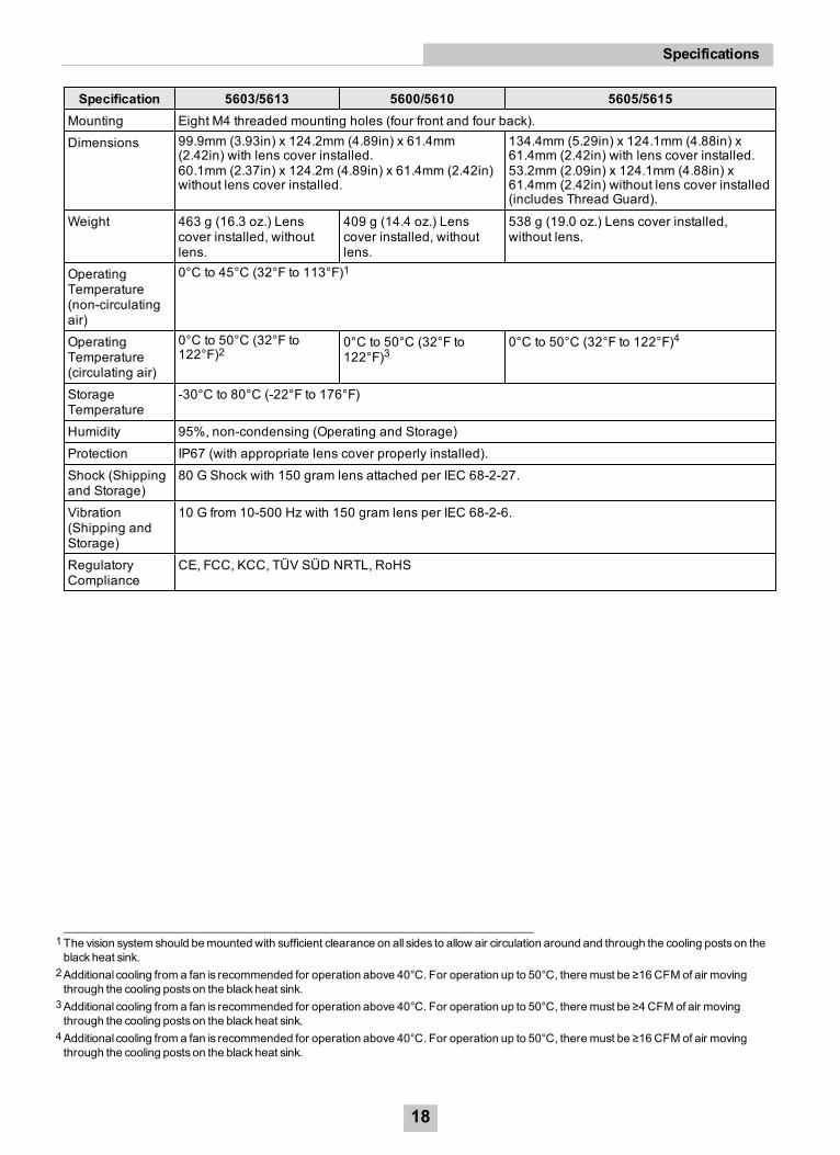
Specification 5603/5613 5600/5610 5605/5615Mounting Eight M4 threaded mounting holes (four front and four back).
Dimensions 99.9mm (3.93in) x 124.2mm (4.89in) x 61.4mm(2.42in) with lens cover installed.60.1mm (2.37in) x 124.2m (4.89in) x 61.4mm (2.42in)without lens cover installed.
134.4mm (5.29in) x 124.1mm (4.88in) x61.4mm (2.42in) with lens cover installed.53.2mm (2.09in) x 124.1mm (4.88in) x61.4mm (2.42in) without lens cover installed(includes Thread Guard).
Weight 463 g (16.3 oz.) Lenscover installed, withoutlens.
409 g (14.4 oz.) Lenscover installed, withoutlens.
538 g (19.0 oz.) Lens cover installed,without lens.
OperatingTemperature(non-circulatingair)
0°C to 45°C (32°F to 113°F)1
OperatingTemperature(circulating air)
0°C to 50°C (32°F to122°F)2
0°C to 50°C (32°F to122°F)3
0°C to 50°C (32°F to 122°F)4
StorageTemperature
-30°C to 80°C (-22°F to 176°F)
Humidity 95%, non-condensing (Operating and Storage)
Protection IP67 (with appropriate lens cover properly installed).
Shock (Shippingand Storage)
80 G Shock with 150 gram lens attached per IEC 68-2-27.
Vibration(Shipping andStorage)
10 G from 10-500 Hz with 150 gram lens per IEC 68-2-6.
RegulatoryCompliance
CE, FCC, KCC, TÜV SÜD NRTL, RoHS
1The vision system should bemounted with sufficient clearance on all sides to allow air circulation around and through the cooling posts on theblackheat sink.
2Additional cooling from a fan is recommended for operation above 40°C. For operation up to 50°C, theremust be ≥16 CFM of air movingthrough the cooling posts on the blackheat sink.
3Additional cooling from a fan is recommended for operation above 40°C. For operation up to 50°C, theremust be ≥4 CFM of air movingthrough the cooling posts on the blackheat sink.
4Additional cooling from a fan is recommended for operation above 40°C. For operation up to 50°C, theremust be ≥16 CFM of air movingthrough the cooling posts on the blackheat sink.
18
Specifications
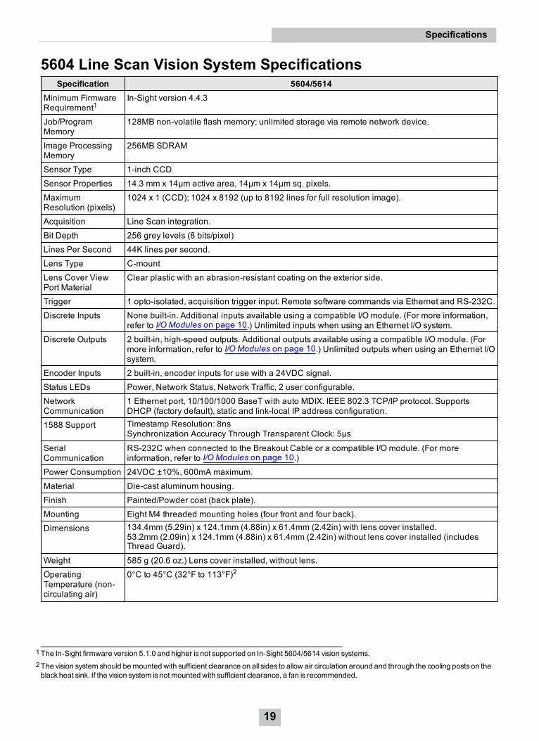
5604 Line Scan Vision System SpecificationsSpecification 5604/5614
Minimum FirmwareRequirement1
In-Sight version 4.4.3
Job/ProgramMemory
128MB non-volatile flash memory; unlimited storage via remote network device.
Image ProcessingMemory
256MB SDRAM
Sensor Type 1-inch CCD
Sensor Properties 14.3 mm x 14µm active area, 14µm x 14µm sq. pixels.
MaximumResolution (pixels)
1024 x 1 (CCD); 1024 x 8192 (up to 8192 lines for full resolution image).
Acquisition Line Scan integration.
Bit Depth 256 grey levels (8 bits/pixel)
Lines Per Second 44K lines per second.
Lens Type C-mount
Lens Cover ViewPort Material
Clear plastic with an abrasion-resistant coating on the exterior side.
Trigger 1 opto-isolated, acquisition trigger input. Remote software commands via Ethernet and RS-232C.
Discrete Inputs None built-in. Additional inputs available using a compatible I/O module. (For more information,refer to I/O Modules on page 10.) Unlimited inputs when using an Ethernet I/O system.
Discrete Outputs 2 built-in, high-speed outputs. Additional outputs available using a compatible I/O module. (Formore information, refer to I/O Modules on page 10.) Unlimited outputs when using an Ethernet I/Osystem.
Encoder Inputs 2 built-in, encoder inputs for use with a 24VDC signal.
Status LEDs Power, Network Status, Network Traffic, 2 user configurable.
NetworkCommunication
1 Ethernet port, 10/100/1000 BaseT with auto MDIX. IEEE 802.3 TCP/IP protocol. SupportsDHCP (factory default), static and link-local IP address configuration.
1588 Support Timestamp Resolution: 8nsSynchronization Accuracy Through Transparent Clock: 5µs
SerialCommunication
RS-232C when connected to the Breakout Cable or a compatible I/O module. (For moreinformation, refer to I/O Modules on page 10.)
Power Consumption 24VDC ±10%, 600mA maximum.
Material Die-cast aluminum housing.
Finish Painted/Powder coat (back plate).
Mounting Eight M4 threaded mounting holes (four front and four back).
Dimensions 134.4mm (5.29in) x 124.1mm (4.88in) x 61.4mm (2.42in) with lens cover installed.53.2mm (2.09in) x 124.1mm (4.88in) x 61.4mm (2.42in) without lens cover installed (includesThread Guard).
Weight 585 g (20.6 oz.) Lens cover installed, without lens.
OperatingTemperature (non-circulating air)
0°C to 45°C (32°F to 113°F)2
1The In-Sight firmware version 5.1.0 and higher is not supported on In-Sight 5604/5614 vision systems.2The vision system should bemounted with sufficient clearance on all sides to allow air circulation around and through the cooling posts on theblackheat sink. If the vision system is not mounted with sufficient clearance, a fan is recommended.
19
Specifications
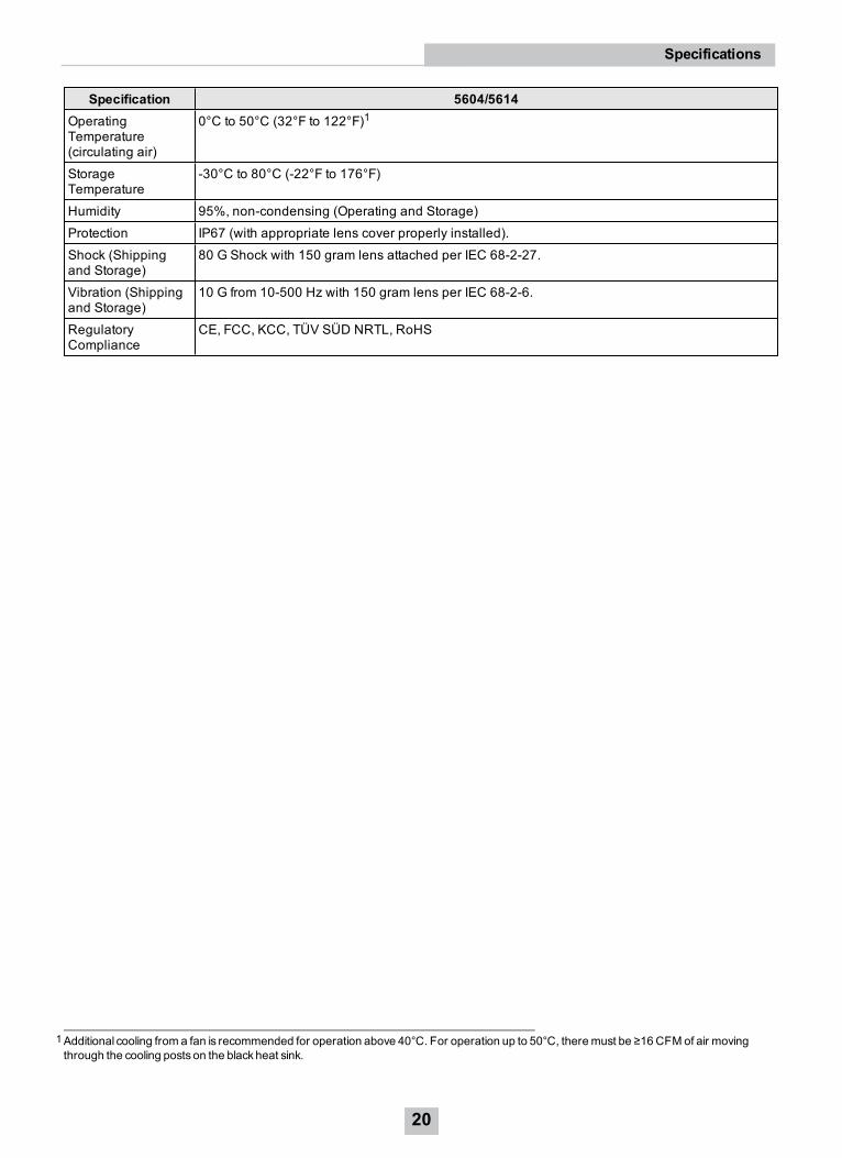
Specification 5604/5614OperatingTemperature(circulating air)
0°C to 50°C (32°F to 122°F)1
StorageTemperature
-30°C to 80°C (-22°F to 176°F)
Humidity 95%, non-condensing (Operating and Storage)
Protection IP67 (with appropriate lens cover properly installed).
Shock (Shippingand Storage)
80 G Shock with 150 gram lens attached per IEC 68-2-27.
Vibration (Shippingand Storage)
10 G from 10-500 Hz with 150 gram lens per IEC 68-2-6.
RegulatoryCompliance
CE, FCC, KCC, TÜV SÜD NRTL, RoHS
1Additional cooling from a fan is recommended for operation above 40°C. For operation up to 50°C, theremust be ≥16 CFM of air movingthrough the cooling posts on the blackheat sink.
20
Specifications
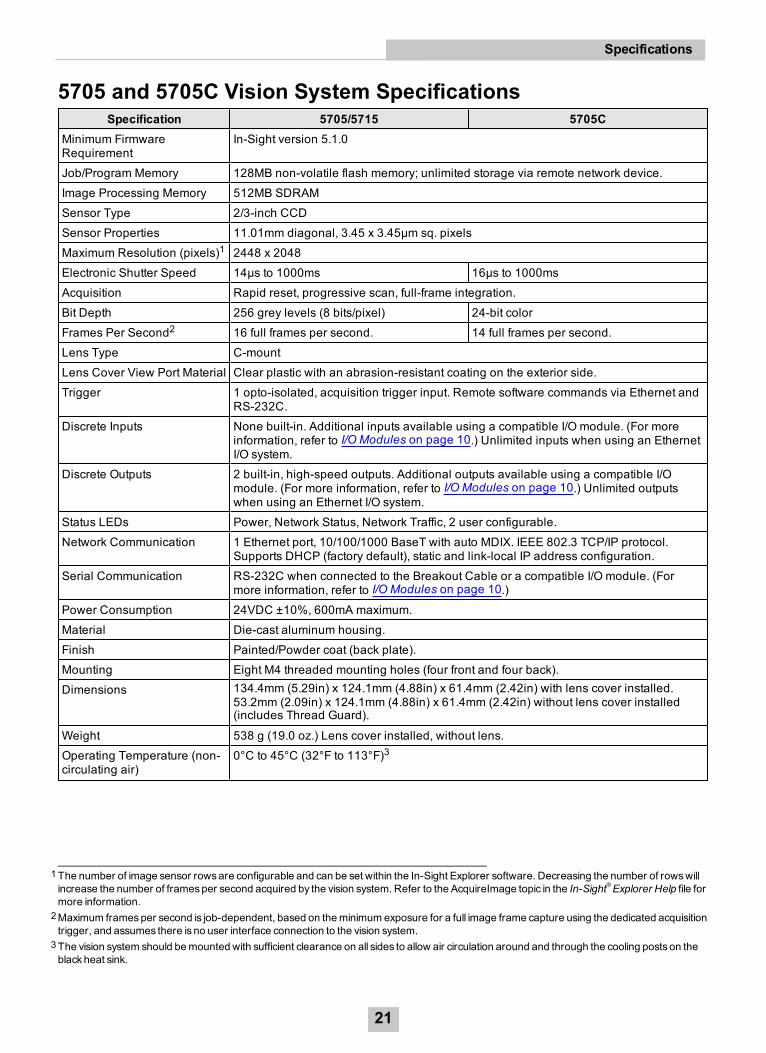
5705 and 5705C Vision System SpecificationsSpecification 5705/5715 5705C
Minimum FirmwareRequirement
In-Sight version 5.1.0
Job/Program Memory 128MB non-volatile flash memory; unlimited storage via remote network device.
Image Processing Memory 512MB SDRAM
Sensor Type 2/3-inch CCD
Sensor Properties 11.01mm diagonal, 3.45 x 3.45µm sq. pixels
Maximum Resolution (pixels)1 2448 x 2048
Electronic Shutter Speed 14µs to 1000ms 16µs to 1000ms
Acquisition Rapid reset, progressive scan, full-frame integration.
Bit Depth 256 grey levels (8 bits/pixel) 24-bit color
Frames Per Second2 16 full frames per second. 14 full frames per second.
Lens Type C-mount
Lens Cover View Port Material Clear plastic with an abrasion-resistant coating on the exterior side.
Trigger 1 opto-isolated, acquisition trigger input. Remote software commands via Ethernet andRS-232C.
Discrete Inputs None built-in. Additional inputs available using a compatible I/O module. (For moreinformation, refer to I/O Modules on page 10.) Unlimited inputs when using an EthernetI/O system.
Discrete Outputs 2 built-in, high-speed outputs. Additional outputs available using a compatible I/Omodule. (For more information, refer to I/O Modules on page 10.) Unlimited outputswhen using an Ethernet I/O system.
Status LEDs Power, Network Status, Network Traffic, 2 user configurable.
Network Communication 1 Ethernet port, 10/100/1000 BaseT with auto MDIX. IEEE 802.3 TCP/IP protocol.Supports DHCP (factory default), static and link-local IP address configuration.
Serial Communication RS-232C when connected to the Breakout Cable or a compatible I/O module. (Formore information, refer to I/O Modules on page 10.)
Power Consumption 24VDC ±10%, 600mA maximum.
Material Die-cast aluminum housing.
Finish Painted/Powder coat (back plate).
Mounting Eight M4 threaded mounting holes (four front and four back).
Dimensions 134.4mm (5.29in) x 124.1mm (4.88in) x 61.4mm (2.42in) with lens cover installed.53.2mm (2.09in) x 124.1mm (4.88in) x 61.4mm (2.42in) without lens cover installed(includes Thread Guard).
Weight 538 g (19.0 oz.) Lens cover installed, without lens.
Operating Temperature (non-circulating air)
0°C to 45°C (32°F to 113°F)3
1The number of image sensor rowsare configurable and can be set within the In-Sight Explorer software. Decreasing the number of rowswillincrease the number of framesper second acquired by the vision system. Refer to the AcquireImage topic in the In-Sight®Explorer Help file formore information.
2Maximum framesper second is job-dependent, based on theminimum exposure for a full image frame capture using the dedicated acquisitiontrigger, and assumes there is no user interface connection to the vision system.
3The vision system should bemounted with sufficient clearance on all sides to allow air circulation around and through the cooling posts on theblackheat sink.
21
Specifications
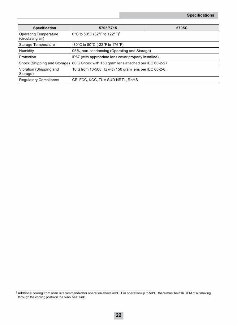
Specification 5705/5715 5705COperating Temperature(circulating air)
0°C to 50°C (32°F to 122°F)1
Storage Temperature -30°C to 80°C (-22°F to 176°F)
Humidity 95%, non-condensing (Operating and Storage)
Protection IP67 (with appropriate lens cover properly installed).
Shock (Shipping and Storage) 80 G Shock with 150 gram lens attached per IEC 68-2-27.
Vibration (Shipping andStorage)
10 G from 10-500 Hz with 150 gram lens per IEC 68-2-6.
Regulatory Compliance CE, FCC, KCC, TÜV SÜD NRTL, RoHS
1Additional cooling from a fan is recommended for operation above 40°C. For operation up to 50°C, theremust be ≥16 CFM of air movingthrough the cooling posts on the blackheat sink.
22
Specifications
I/O SpecificationsCable and connector specifications and connection examples for the acquisition trigger input, encoder inputs (In-Sight5604 only) and the high-speed outputs are provided in the following sections.
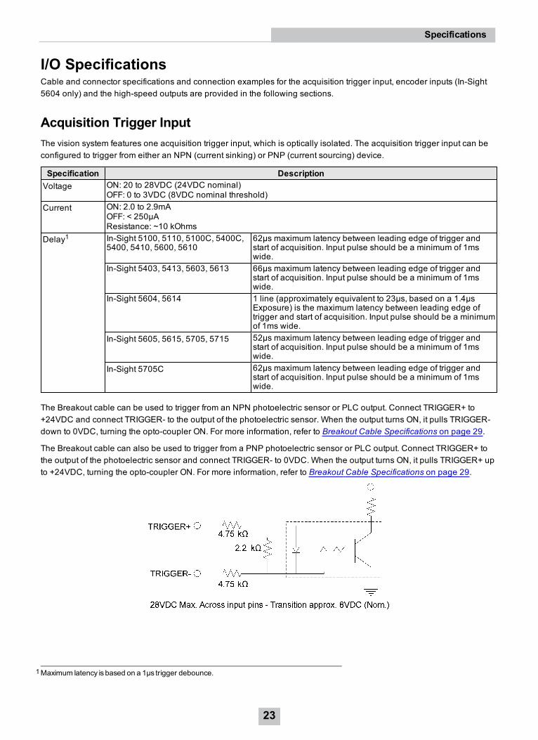
Acquisition Trigger InputThe vision system features one acquisition trigger input, which is optically isolated. The acquisition trigger input can beconfigured to trigger from either an NPN (current sinking) or PNP (current sourcing) device.
Specification DescriptionVoltage ON: 20 to 28VDC (24VDC nominal)
OFF: 0 to 3VDC (8VDC nominal threshold)Current ON: 2.0 to 2.9mA
OFF: < 250µAResistance: ~10 kOhms
Delay1 In-Sight 5100, 5110, 5100C, 5400C,5400, 5410, 5600, 5610
62µs maximum latency between leading edge of trigger andstart of acquisition. Input pulse should be a minimum of 1mswide.
In-Sight 5403, 5413, 5603, 5613 66µs maximum latency between leading edge of trigger andstart of acquisition. Input pulse should be a minimum of 1mswide.
In-Sight 5604, 5614 1 line (approximately equivalent to 23µs, based on a 1.4µsExposure) is the maximum latency between leading edge oftrigger and start of acquisition. Input pulse should be a minimumof 1ms wide.
In-Sight 5605, 5615, 5705, 5715 52µs maximum latency between leading edge of trigger andstart of acquisition. Input pulse should be a minimum of 1mswide.
In-Sight 5705C 62µs maximum latency between leading edge of trigger andstart of acquisition. Input pulse should be a minimum of 1mswide.
The Breakout cable can be used to trigger from an NPN photoelectric sensor or PLC output. Connect TRIGGER+ to+24VDC and connect TRIGGER- to the output of the photoelectric sensor. When the output turns ON, it pulls TRIGGER-down to 0VDC, turning the opto-coupler ON. For more information, refer to Breakout Cable Specifications on page 29.
The Breakout cable can also be used to trigger from a PNP photoelectric sensor or PLC output. Connect TRIGGER+ tothe output of the photoelectric sensor and connect TRIGGER- to 0VDC. When the output turns ON, it pulls TRIGGER+ upto +24VDC, turning the opto-coupler ON. For more information, refer to Breakout Cable Specifications on page 29.
1Maximum latency is based on a 1µs trigger debounce.
23
Specifications
Note: When using the vision system with the Breakout cable, the polarity of the TRIGGER+ and TRIGGER- pins isnot critical. However, when using an optional I/O module, the polarity of the TRIGGER+ and TRIGGER- pins shouldbe observed.
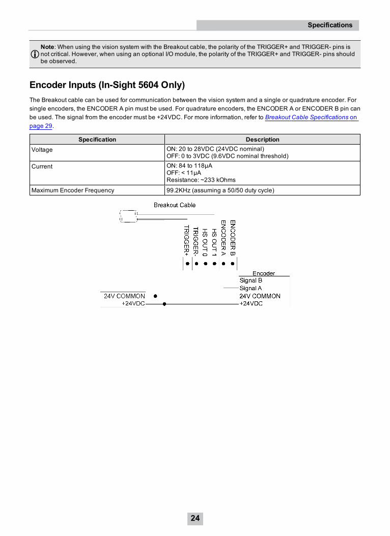
Encoder Inputs (In-Sight 5604 Only)The Breakout cable can be used for communication between the vision system and a single or quadrature encoder. Forsingle encoders, the ENCODER A pin must be used. For quadrature encoders, the ENCODER A or ENCODER B pin canbe used. The signal from the encoder must be +24VDC. For more information, refer to Breakout Cable Specifications onpage 29.
Specification DescriptionVoltage ON: 20 to 28VDC (24VDC nominal)
OFF: 0 to 3VDC (9.6VDC nominal threshold)
Current ON: 84 to 118µAOFF: < 11µAResistance: ~233 kOhms
Maximum Encoder Frequency 99.2KHz (assuming a 50/50 duty cycle)
24
Specifications
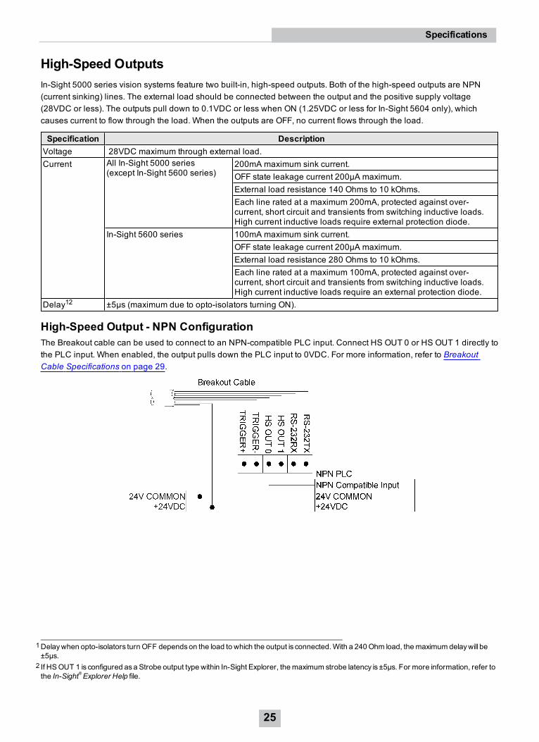
High-Speed OutputsIn-Sight 5000 series vision systems feature two built-in, high-speed outputs. Both of the high-speed outputs are NPN(current sinking) lines. The external load should be connected between the output and the positive supply voltage(28VDC or less). The outputs pull down to 0.1VDC or less when ON (1.25VDC or less for In-Sight 5604 only), whichcauses current to flow through the load. When the outputs are OFF, no current flows through the load.
Specification DescriptionVoltage 28VDC maximum through external load.Current All In-Sight 5000 series
(except In-Sight 5600 series)200mA maximum sink current.OFF state leakage current 200µA maximum.External load resistance 140 Ohms to 10 kOhms.Each line rated at a maximum 200mA, protected against over-current, short circuit and transients from switching inductive loads.High current inductive loads require external protection diode.
In-Sight 5600 series 100mA maximum sink current.OFF state leakage current 200µA maximum.External load resistance 280 Ohms to 10 kOhms.Each line rated at a maximum 100mA, protected against over-current, short circuit and transients from switching inductive loads.High current inductive loads require an external protection diode.
Delay12 ±5µs (maximum due to opto-isolators turning ON).
High-Speed Output - NPN ConfigurationThe Breakout cable can be used to connect to an NPN-compatible PLC input. Connect HS OUT 0 or HS OUT 1 directly tothe PLC input. When enabled, the output pulls down the PLC input to 0VDC. For more information, refer to BreakoutCable Specifications on page 29.
1Delaywhen opto-isolators turn OFF dependson the load to which the output is connected.With a 240Ohm load, themaximum delaywill be±5µs.
2 If HSOUT 1 is configured asa Strobe output type within In-Sight Explorer, themaximum strobe latency is ±5µs. For more information, refer tothe In-Sight®Explorer Help file.
25
Specifications
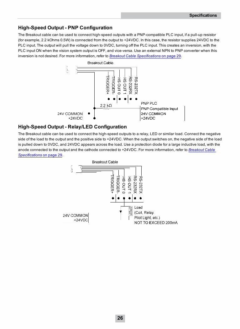
High-Speed Output - PNP ConfigurationThe Breakout cable can be used to connect high-speed outputs with a PNP-compatible PLC input, if a pull-up resistor(for example, 2.2 kOhms 0.5W) is connected from the output to +24VDC. In this case, the resistor supplies 24VDC to thePLC input. The output will pull the voltage down to 0VDC, turning off the PLC input. This creates an inversion, with thePLC input ON when the vision system output is OFF, and vice-versa. Use an external NPN to PNP converter when thisinversion is not desired. For more information, refer to Breakout Cable Specifications on page 29.
High-Speed Output - Relay/LED ConfigurationThe Breakout cable can be used to connect the high-speed outputs to a relay, LED or similar load. Connect the negativeside of the load to the output and the positive side to +24VDC. When the output switches on, the negative side of the loadis pulled down to 0VDC, and 24VDC appears across the load. Use a protection diode for a large inductive load, with theanode connected to the output and the cathode connected to +24VDC. For more information, refer to Breakout CableSpecifications on page 29.
26
Specifications
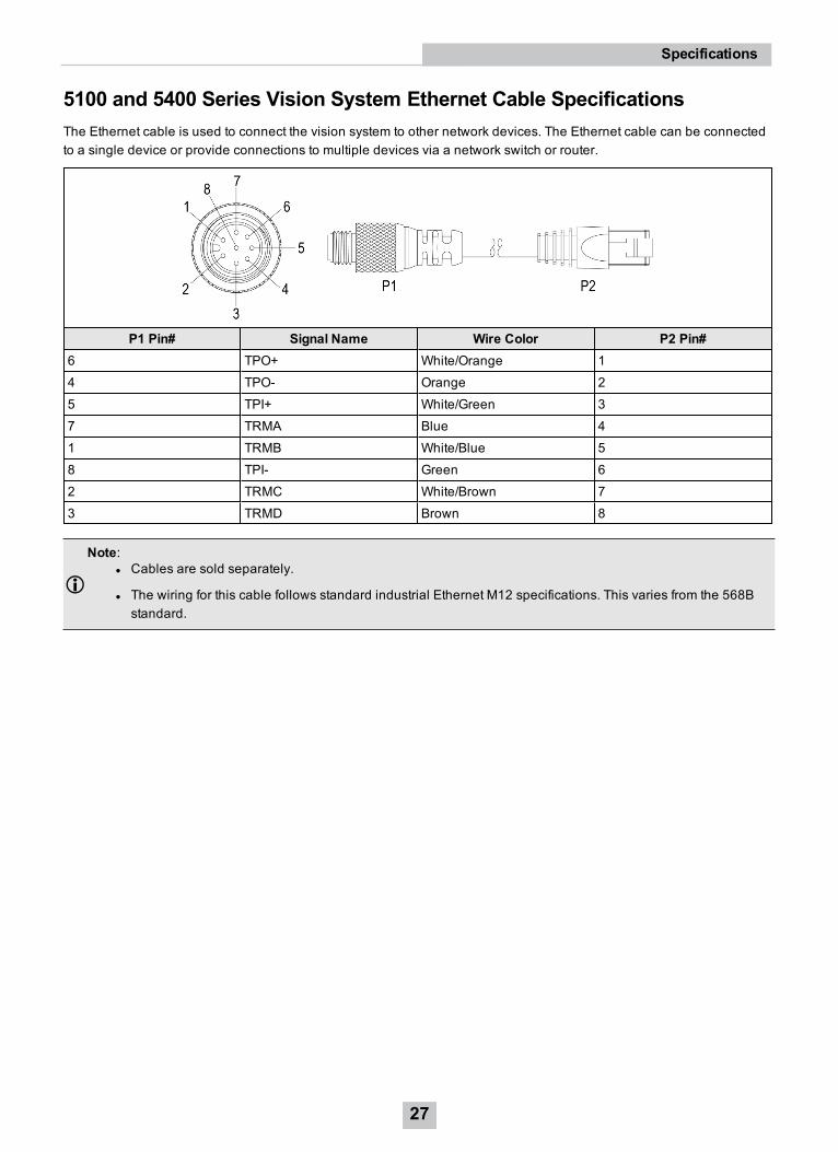
5100 and 5400 Series Vision System Ethernet Cable SpecificationsThe Ethernet cable is used to connect the vision system to other network devices. The Ethernet cable can be connectedto a single device or provide connections to multiple devices via a network switch or router.
P1 Pin# Signal Name Wire Color P2 Pin#6 TPO+ White/Orange 1
4 TPO- Orange 2
5 TPI+ White/Green 3
7 TRMA Blue 4
1 TRMB White/Blue 5
8 TPI- Green 6
2 TRMC White/Brown 7
3 TRMD Brown 8
Note:l Cables are sold separately.
l The wiring for this cable follows standard industrial Ethernet M12 specifications. This varies from the 568Bstandard.
27
Specifications
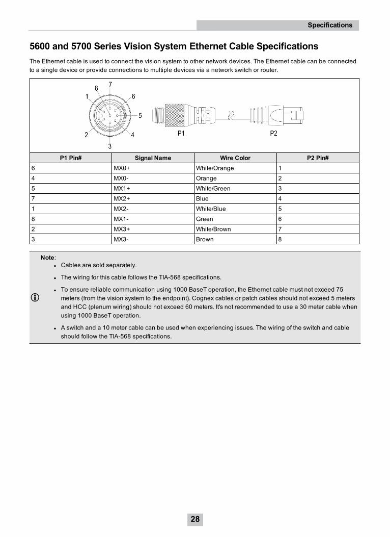
5600 and 5700 Series Vision System Ethernet Cable SpecificationsThe Ethernet cable is used to connect the vision system to other network devices. The Ethernet cable can be connectedto a single device or provide connections to multiple devices via a network switch or router.
P1 Pin# Signal Name Wire Color P2 Pin#6 MX0+ White/Orange 1
4 MX0- Orange 2
5 MX1+ White/Green 3
7 MX2+ Blue 4
1 MX2- White/Blue 5
8 MX1- Green 6
2 MX3+ White/Brown 7
3 MX3- Brown 8
Note:l Cables are sold separately.
l The wiring for this cable follows the TIA-568 specifications.
l To ensure reliable communication using 1000 BaseT operation, the Ethernet cable must not exceed 75meters (from the vision system to the endpoint). Cognex cables or patch cables should not exceed 5 metersand HCC (plenum wiring) should not exceed 60 meters. It's not recommended to use a 30 meter cable whenusing 1000 BaseT operation.
l A switch and a 10 meter cable can be used when experiencing issues. The wiring of the switch and cableshould follow the TIA-568 specifications.
28
Specifications
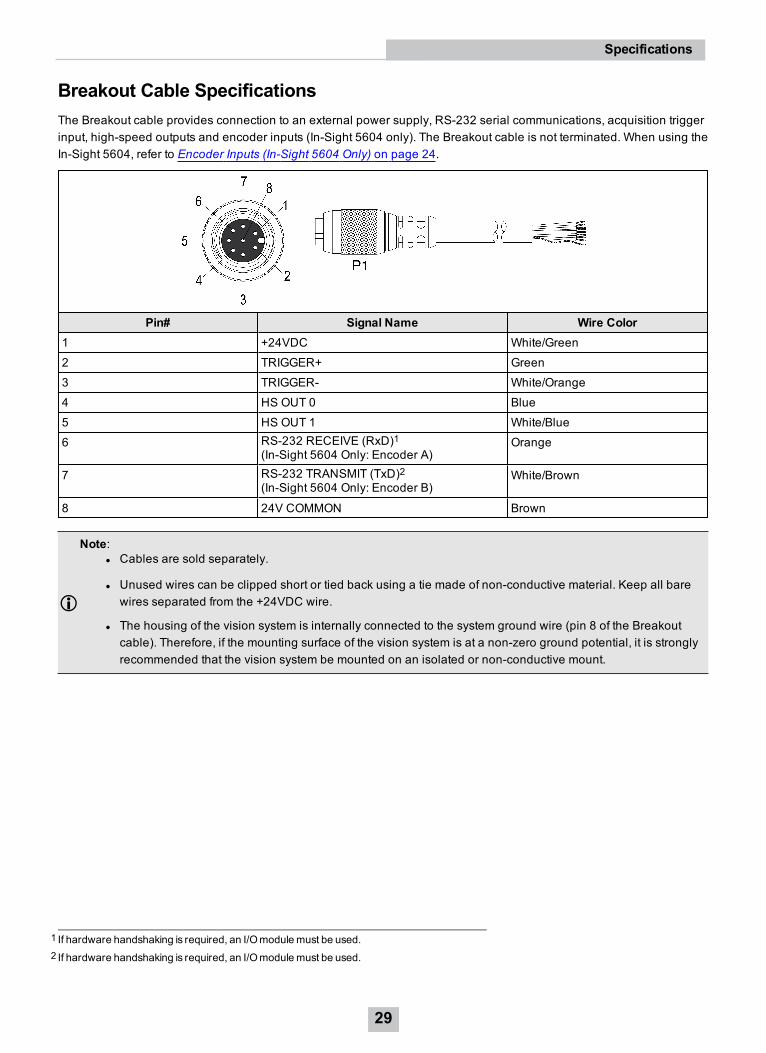
Breakout Cable SpecificationsThe Breakout cable provides connection to an external power supply, RS-232 serial communications, acquisition triggerinput, high-speed outputs and encoder inputs (In-Sight 5604 only). The Breakout cable is not terminated. When using theIn-Sight 5604, refer to Encoder Inputs (In-Sight 5604 Only) on page 24.
Pin# Signal Name Wire Color1 +24VDC White/Green
2 TRIGGER+ Green
3 TRIGGER- White/Orange
4 HS OUT 0 Blue
5 HS OUT 1 White/Blue
6 RS-232 RECEIVE (RxD)1(In-Sight 5604 Only: Encoder A)
Orange
7 RS-232 TRANSMIT (TxD)2(In-Sight 5604 Only: Encoder B)
White/Brown
8 24V COMMON Brown
Note:l Cables are sold separately.
l Unused wires can be clipped short or tied back using a tie made of non-conductive material. Keep all barewires separated from the +24VDC wire.
l The housing of the vision system is internally connected to the system ground wire (pin 8 of the Breakoutcable). Therefore, if the mounting surface of the vision system is at a non-zero ground potential, it is stronglyrecommended that the vision system be mounted on an isolated or non-conductive mount.
1 If hardware handshaking is required, an I/Omodulemust be used.2 If hardware handshaking is required, an I/Omodulemust be used.
29
Specifications
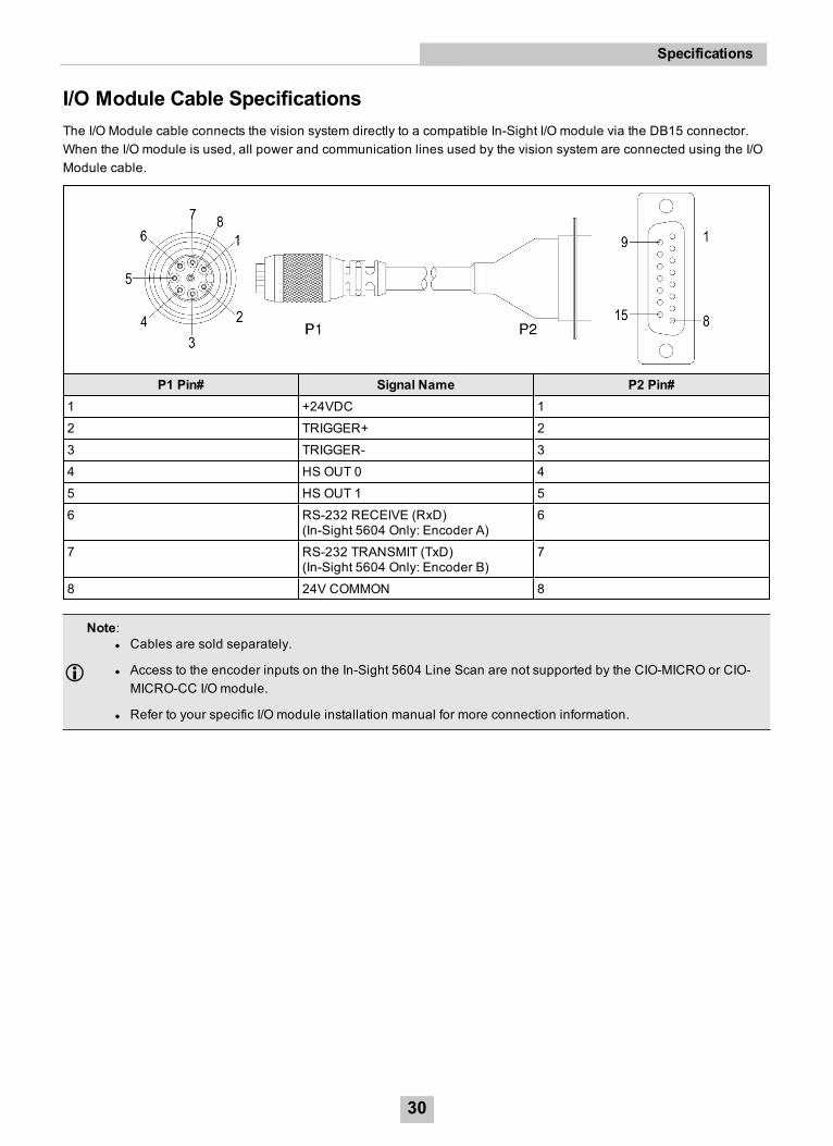
I/O Module Cable SpecificationsThe I/O Module cable connects the vision system directly to a compatible In-Sight I/O module via the DB15 connector.When the I/O module is used, all power and communication lines used by the vision system are connected using the I/OModule cable.
P1 Pin# Signal Name P2 Pin#1 +24VDC 1
2 TRIGGER+ 2
3 TRIGGER- 3
4 HS OUT 0 4
5 HS OUT 1 5
6 RS-232 RECEIVE (RxD)(In-Sight 5604 Only: Encoder A)
6
7 RS-232 TRANSMIT (TxD)(In-Sight 5604 Only: Encoder B)
7
8 24V COMMON 8
Note:l Cables are sold separately.
l Access to the encoder inputs on the In-Sight 5604 Line Scan are not supported by the CIO-MICRO or CIO-MICRO-CC I/O module.
l Refer to your specific I/O module installation manual for more connection information.
30
Specifications
Dimensional Drawings
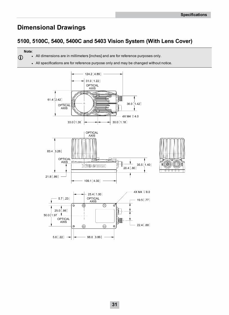
5100, 5100C, 5400, 5400C and 5403 Vision System (With Lens Cover)Note:
l All dimensions are in millimeters [inches] and are for reference purposes only.
l All specifications are for reference purpose only and may be changed without notice.
31
Specifications
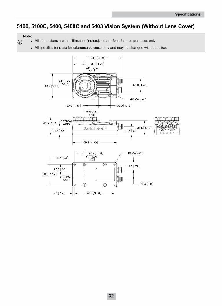
5100, 5100C, 5400, 5400C and 5403 Vision System (Without Lens Cover)Note:
l All dimensions are in millimeters [inches] and are for reference purposes only.
l All specifications are for reference purpose only and may be changed without notice.
32
Specifications
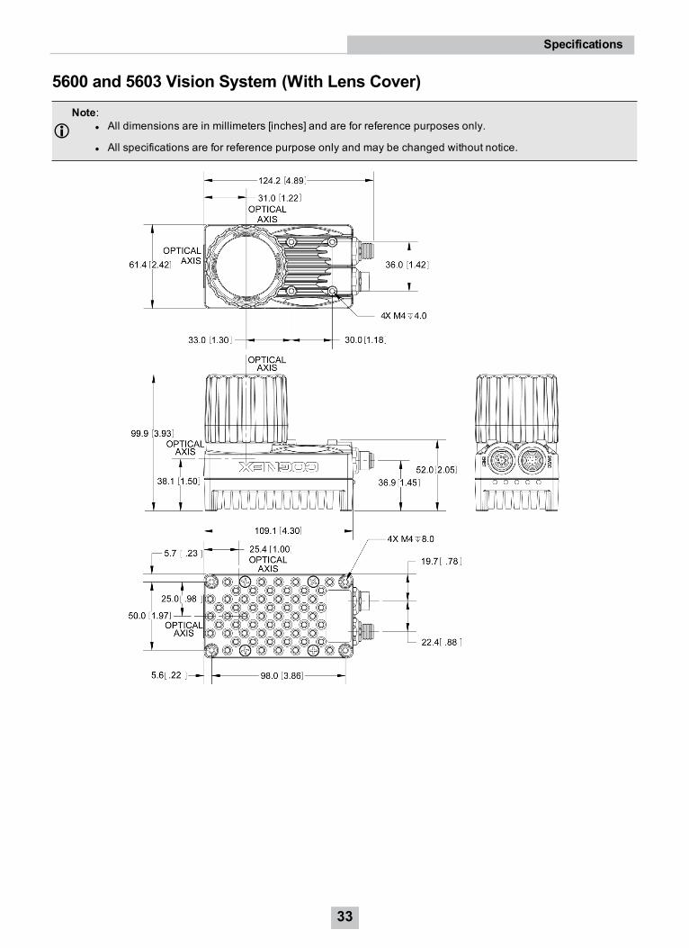
5600 and 5603 Vision System (With Lens Cover)Note:
l All dimensions are in millimeters [inches] and are for reference purposes only.
l All specifications are for reference purpose only and may be changed without notice.
33
Specifications
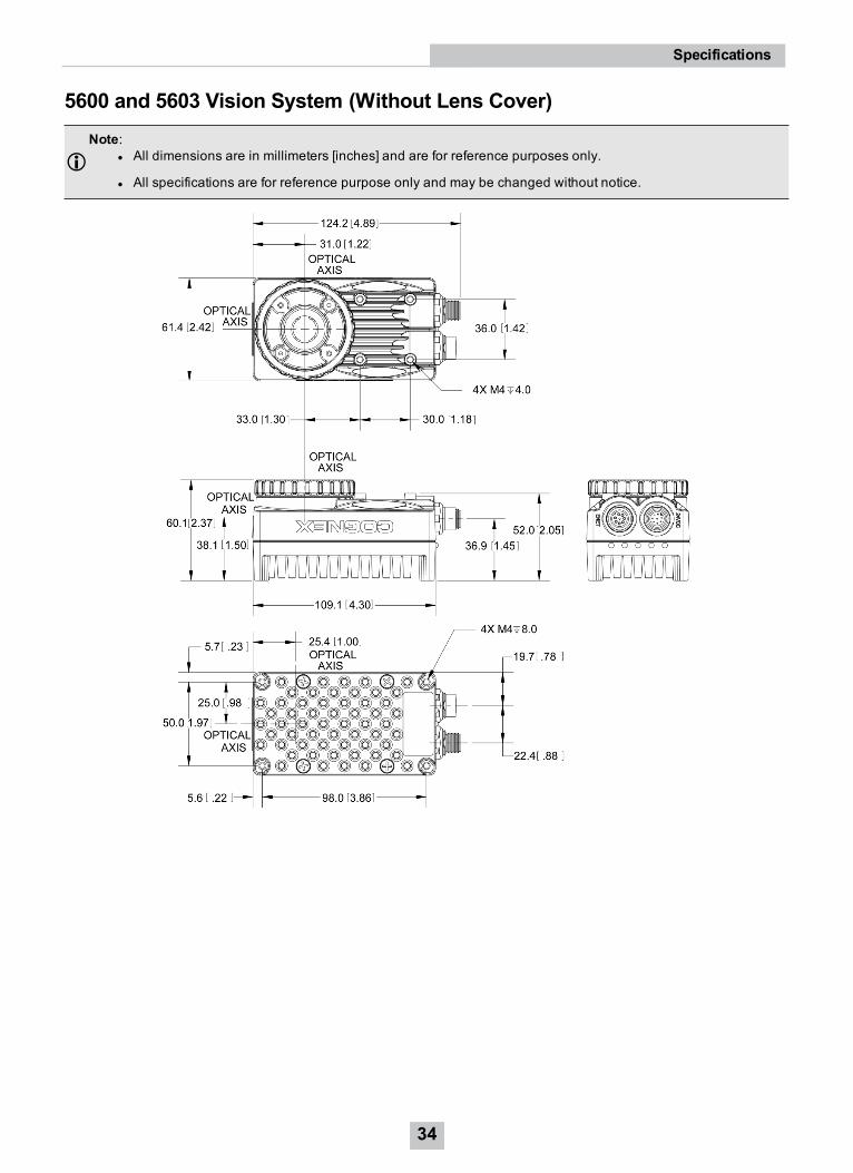
5600 and 5603 Vision System (Without Lens Cover)Note:
l All dimensions are in millimeters [inches] and are for reference purposes only.
l All specifications are for reference purpose only and may be changed without notice.
34
Specifications
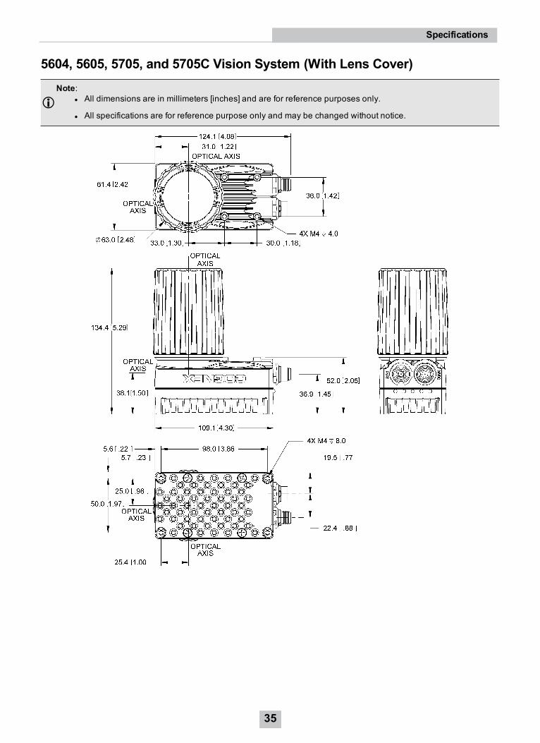
5604, 5605, 5705, and 5705C Vision System (With Lens Cover)Note:
l All dimensions are in millimeters [inches] and are for reference purposes only.
l All specifications are for reference purpose only and may be changed without notice.
35
Specifications
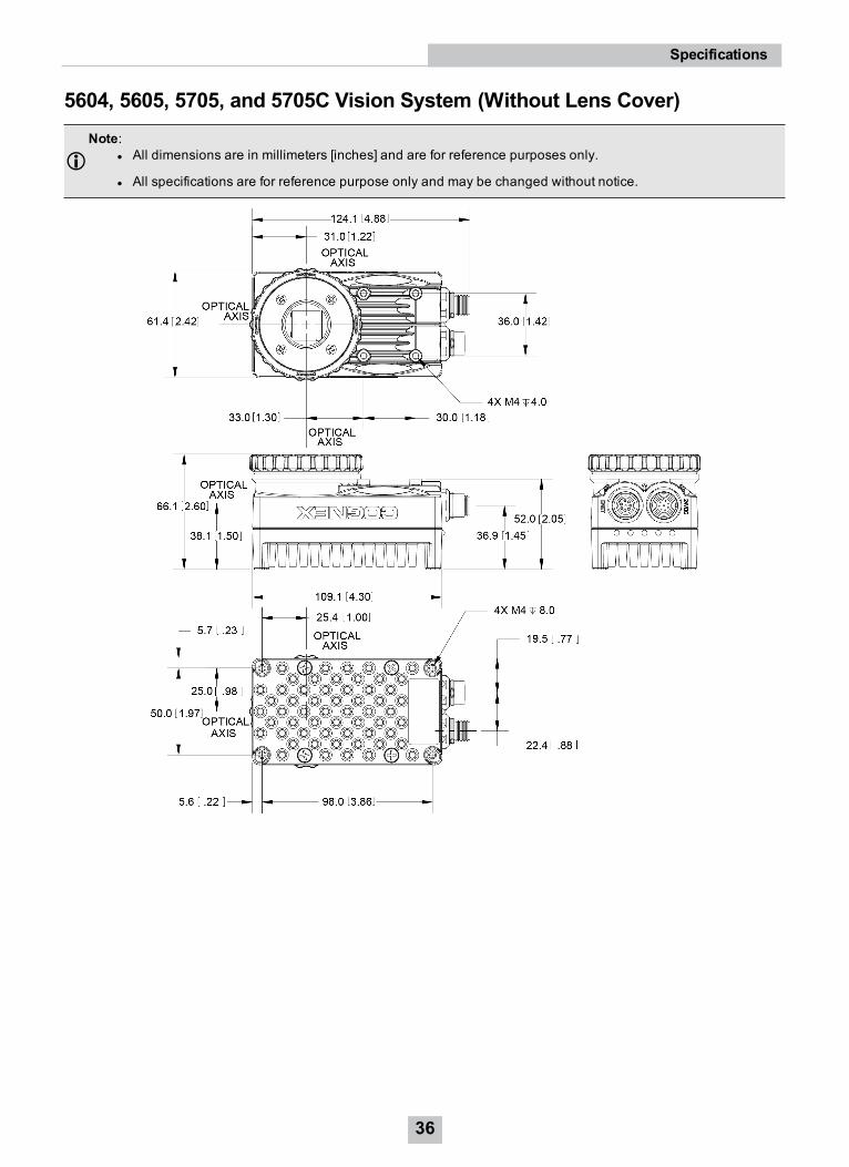
5604, 5605, 5705, and 5705C Vision System (Without Lens Cover)Note:
l All dimensions are in millimeters [inches] and are for reference purposes only.
l All specifications are for reference purpose only and may be changed without notice.
36
Specifications
Cleaning/MaintenanceClean the Vision System HousingTo clean the outside of the vision system housing, use a small amount of mild detergent cleaner or isopropyl alcohol ona cleaning cloth. Do not pour the cleaner directly onto the vision system housing.
CAUTION: Do not attempt to clean any In-Sight product with harsh or corrosive solvents, including lye, methyl ethylketone (MEK) or gasoline.
Clean the Vision System Image Sensor WindowTo remove dust from the outside of the image sensor window, use a pressurized air duster. The air must be free of oil,moisture or other contaminants that could remain on the glass and possibly degrade the image. Do not touch the glasswindow. If oil/smudges still remain, clean the window with a cotton bud using alcohol (ethyl, methyl or isopropyl). Do notpour the alcohol directly on the window.
Clean the Vision System Lens CoverTo remove dust from the lens cover, use a pressurized air duster. The air must be free of oil, moisture or othercontaminants that could remain on the lens cover. To clean the plastic window of the lens cover, use a small amount ofisopropyl alcohol on a cleaning cloth. Do not scratch the plastic window. Do not pour the alcohol directly on the plasticwindow.
37
Cleaning/Maintenance