Embed Size (px)
Citation preview
In-Sight® 5000 SeriesVision SystemInstallation Manual

In-Sight® 5000 Series Vision System Installation Manual
Legal NoticesThe software described in this document is furnished under license, and may be used or copied only in accordance with the terms of such license and with the inclusion of the copyright notice shown on this page. Neither the software, this document, nor any copies thereof may be provided to, or otherwise made available to, anyone other than the licensee. Title to, and ownership of, this software remains with Cognex Corporation or its licensor. Cognex Corporation assumes no responsibility for the use or reliability of its software on equipment that is not supplied by Cognex Corporation. Cognex Corporation makes no warranties, either express or implied, regarding the described software, its merchantability, non-infringement or its fitness for any particular purpose.
The information in this document is subject to change without notice and should not be construed as a commitment by Cognex Corporation. Cognex Corporation is not responsible for any errors that may be present in either this document or the associated software.
Companies, names, and data used in examples herein are fictitious unless otherwise noted. No part of this document may be reproduced or transmitted in any form or by any means, electronic or mechanical, for any purpose, nor transferred to any other media or language without the written permission of Cognex Corporation.
Cognex P/N 597-0027-06
Copyright © 2003-2009 Cognex Corporation. All Rights Reserved.
Portions of the hardware and software provided by Cognex may be covered by one or more of the U.S. and foreign patents listed below as well as pending U.S. and foreign patents. Such pending U.S. and foreign patents issued after the date of this document are listed on Cognex web site at http://www.cognex.com/patents. 5481712, 5742037, 5751853, 5845007, 5909504, 5943441, 5949905, 5960125, 5978080, 5978081, 6005978, 6137893, 6141033, 6154567, 6215915, 6236769, 6282328, 6301396, 6327393, 6381375, 6408109, 6457032, 6490600, 6563324, 6658145, 6690842, 6771808, 6804416, 6836567, 6850646, 6856698, 6859907, 6920241, 6941026, 6959112, 6963338, 6975764, 6985625, 6993192, 7006712, 7016539, 7043081, 7058225, 7065262, 7069499, 7088862, 7107519, 7164796, 7175090, 7181066, 7251366, JP 3927239
Cognex, In-Sight, VisionView and DVT are registered trademarks of Cognex Corporation.
The Cognex logo, SmartLink, EdgeCount, FeatureCount, and ObjectLocate are trademarks of Cognex Corporation.
Other product and company trademarks identified herein are the trademarks of their respective owners.
i

Legal Notices
ii

In-Sight® 5000 Series Vision System Installation Manual
Regulations/ConformityNote:
For the most up-to-date regulations and conformity information, please refer to the In-Sight online support site: http://www.cognexsensors.com/In-Sight
Declaration of ConformityManufacturer: Cognex Corporation
One Vision DriveNatick, MA 01760 USA
Declares this -marked Machine Vision System Product
Product Number: In-Sight 5100/5110: P/N 800-5870-1RIn-Sight 5100C: P/N 800-5837-4RIn-Sight 5400/5410: P/N 800-5855-1R In-Sight 5400S/5410S: P/N 800-5855-3RIn-Sight 5400C: P/N 800-5837-4RIn-Sight 5400CS: P/N 800-5837-6RIn-Sight 5401/5411: P/N 800-5838-4R
Complies With: 89/336/EEC Electromagnetic Compatibility DirectiveCompliance Standards EN 55011:1998 + A1:1999 + A2:2002 Class A
EN 61000-3-2:2000 + A2:2005EN 61000-3-3:1995 + A1:2001EN 61000-6-2:2001
European Representative: COGNEX INTERNATIONALImmeuble “Le Patio”104 Avenue Albert 1er92563 Rueil Malmaison Cedex - France
Safety and Regulatory
LISTED
UL and CUL Certification marks are present on products.
FCC FCC Part 15, Class A This device complies with Part 15 of the FCC Rules. Operation is subject to the following two conditions: (1) this device may not cause harmful interference; and (2) this device must accept any interference received, including interference that may cause undesired operation.
This equipment generates, uses, and can radiate radio frequency energy and, if not installed and used in accordance with the instruction manual, may cause harmfulinterference to radio communications. Operation of this equipment in a residential area is likely to cause harmful interference in which case the user will be required to correct the interference at their own expense.
RoHS RoHS 6 Compliant.
iii

Regulations/Conformity
Declaration of ConformityManufacturer: Cognex Corporation
One Vision DriveNatick, MA 01760 USA
Declares this -marked Machine Vision System Product
Product Number: In-Sight 5400R/5410R: P/N 800-5829-1RComplies With: 89/336/EEC Electromagnetic Compatibility DirectiveCompliance Standards EN 61000-6-4:2001 Class A
EN 61000-3-2:2000 + A2:2005EN 61000-3-3:1995 + A1:2001EN 61000-6-2:2001
European Representative: COGNEX INTERNATIONALImmeuble “Le Patio”104 Avenue Albert 1er92563 Rueil Malmaison Cedex - France
Safety and Regulatory
LISTED
UL and CUL Certification marks are present on products.
FCC FCC Part 15, Class AThis device complies with Part 15 of the FCC Rules. Operation is subject to the following two conditions: (1) This device may not cause harmful interference, and (2) this device must accept any interference received, including interference that may cause undesired operation.
This equipment generates, uses, and can radiate radio frequency energy and, if not installed and used in accordance with the instruction manual, may cause harmful interfer-ence to radio communications. Operation of this equipment in a residential area is likely to cause harmful interference in which case the user will be required to correct the interfer-ence at their own expense.
RoHS RoHS 6 Compliant.
iv

In-Sight® 5000 Series Vision System Installation Manual
Declaration of ConformityManufacturer: Cognex Corporation
One Vision DriveNatick, MA 01760 USA
Declares this -marked Machine Vision System Product
Product Number: In-Sight 5403/5413: P/N 800-5830-4RIn-Sight 5403S: P/N 800-5830-6R
Complies With: 89/336/EEC Electromagnetic Compatibility DirectiveCompliance Standards EN 61000-6-3:2001 + A11:2004 Class B
EN 61000-3-2:2000 + A2:2005EN 61000-3-3:1995 + A1:2001EN 61000-6-2:2001
European Representative: COGNEX INTERNATIONALImmeuble “Le Patio”104 Avenue Albert 1er92563 Rueil Malmaison Cedex - France
Safety and Regulatory
LISTED
UL and CUL Certification marks are present on products.
FCC FCC Part 15, Class BThis device complies with Part 15 of the FCC Rules. Operation is subject to the following two conditions: (1) This device may not cause harmful interference, and (2) this device must accept any interference received, including interference that may cause undesired operation.
RoHS RoHS 6 Compliant.
v

Regulations/Conformity
Declaration of ConformityManufacturer: Cognex Corporation
One Vision DriveNatick, MA 01760 USA
Declares this -marked Machine Vision System Product
Product Number/Product Type:
In-Sight 5600: P/N 800-5871-1RIn-Sight 5603: P/N 800-5873-1RIn-Sight 5604: P/N 800-5874-1R
Complies With: 89/336/EEC Electromagnetic Compatibility DirectiveCompliance StandardsClass A1
EN 61000-6-4:2001 Class AEN 61000-3-2:2000 + A2:2005EN 61000-3-3:1995 + A1:2001 +A2:2005EN 61000-6-2:2005
Compliance StandardsClass B2
EN 61000-6-3:2001 +A11:2004 Class BEN 55022:1988 +A1:2000 +A2:2003 Class BEN 61000-3-2:2000 + A2:2005EN 61000-3-3:1995 + A1:2001 +A2:2005EN 61000-6-2:2005
European Representative: COGNEX INTERNATIONALImmeuble “Le Patio”104 Avenue Albert 1er92563 Rueil Malmaison Cedex - France
Safety and Regulatory
LISTED
UL and CUL Certification marks are present on products.
FCCClass A1
FCC Part 15, Class A This device complies with Part 15 of the FCC Rules. Operation is subject to the following two conditions: (1) This device may not cause harmful interference, and (2) this device must accept any interference received, including interference that may cause undesired operation.
This equipment generates, uses, and can radiate radio frequency energy and, if not installed and used in accordance with the instruction manual, may cause harmful interference to radio communications. Operation of this equipment in a residential area is likely to cause harmful interference in which case the user will be required to correct the interference at their own expense.
FCCClass B2
FCC Part 15, Class BThis device complies with Part 15 of the FCC Rules. Operation is subject to the following two conditions: (1) This device may not cause harmful interference, and (2) this device must accept any interference received, including interference that may cause undesired operation.
RoHS RoHS 6 Compliant.
1. Using Cognex Power Supply ACC-24I or equivalent Class A power supply. 2. Using Cognex Power Supply PS-Kit-1 or equivalent Class B power supply.
vi

In-Sight® 5000 Series Vision System Installation Manual
PrecautionsObserve these precautions when installing In-Sight 5000 series vision systems to reduce the risk of injury or equipment damage:
• In-Sight 5000 series vision systems are intended to be supplied by a Listed, Direct Plug-In Power Unit with a minimum output rated 24VDC, 600mA and marked Class 2, Limited Power Source (LPS). Any other voltage creates a risk of fire or shock and can damage the In-Sight components.
• Do not install In-Sight 5000 series vision systems where they are directly exposed to environmental hazards such as excessive heat, dust, moisture, humidity, impact, vibration, corrosive substances, flammable substances, or static electricity.
• To reduce the risk of damage or malfunction due to over-voltage, line noise, electrostatic discharge (ESD), power surges, or other irregularities in the power supply, route all cables and wires away from high-voltage power sources.
• The housing of the vision system is internally connected to the system ground wire (pin 8 of the Breakout cable). Therefore, if the mounting surface of the vision system is at a non-zero ground potential, it is strongly recommended that the vision system be mounted on an isolated or non-conductive mount.
• Do not expose the CCD to laser light; CCDs can be damaged by direct, or reflected, laser light. If your application requires the use of laser light that may strike the CCD, a lens filter at the corresponding laser's wavelength is recommended. Contact your local integrator or application engineer for suggestions.
• Do not open the In-Sight 5000 series vision system or remote head camera. These devices do not contain user-serviceable parts.
• Do not make electrical or mechanical modifications to In-Sight components. Unauthorized modifications may violate your warranty.
• Changes or modifications not expressly approved by the party responsible for regulatory compliance could void the user’s authority to operate the equipment.
• Cable shielding can be degraded or cables can be damaged or wear out more quickly if a bend radius or service loop is tighter than 10X the cable diameter.
• Service loops should be included with all cable connections.
vii

Precautions
viii

In-Sight® 5000 Series Vision System Installation Manual
Table of Contents1 Introduction
1.1 In-Sight 5000 Series Vision Systems Overview ............................................................... 11.2 In-Sight Support ............................................................................................................... 11.3 In-Sight 5000 Series Standard Components.................................................................... 21.4 I/O Module Compatibility .................................................................................................. 41.5 In-Sight 5000 Series Configurations ................................................................................ 4
1.5.1 Standalone Network.............................................................................................. 51.5.2 Configurations Using Switches/Routers................................................................ 61.5.3 Adding an In-Sight Network to the Factory Network ............................................. 7
2 Installing the Vision System2.1 Connecting the In-Sight 5000 Series Vision System........................................................ 92.2 Connecting the In-Sight 5000 Series Components ........................................................ 10
2.2.1 Install the Lens .................................................................................................... 102.2.2 Attach the Remote Head Camera cable ............................................................. 132.2.3 Connecting the Network and Breakout Cables ................................................... 14
3 Specifications3.1 General Specifications ................................................................................................... 17
3.1.1 In-Sight Standard Vision System Specifications ................................................ 183.1.2 In-Sight Stainless Steel Vision System Specifications ........................................ 203.1.3 In-Sight Remote Head Vision System Specifications.......................................... 223.1.4 In-Sight 5603 and 5600 Vision System Specifications........................................ 243.1.5 In-Sight 5604 Line Scan Vision System Specifications....................................... 26
3.2 I/O Specifications ........................................................................................................... 283.2.1 Acquisition Trigger Input ..................................................................................... 283.2.2 Encoder Inputs (In-Sight 5604 only).................................................................... 293.2.3 High-Speed Outputs............................................................................................ 303.2.4 24VDC Breakout Cable....................................................................................... 323.2.5 I/O Module Cable ................................................................................................ 333.2.6 Ethernet Cable .................................................................................................... 343.2.7 Camera Cable ..................................................................................................... 35
3.3 In-Sight Dimensional Drawings ...................................................................................... 363.3.1 5100, 5100C, 5400, 5401, 5400C and 5403 Vision System Dimensions ........... 363.3.2 5403S, 5400CS and 5400S Vision System Dimensions..................................... 383.3.3 5400R Vision System Dimensions ...................................................................... 403.3.4 Remote Head Camera Dimensions .................................................................... 413.3.5 Remote Head Camera Enclosure Dimensions ................................................... 423.3.6 Remote Head Camera Mount Dimensions ......................................................... 433.3.7 5600 and 5603 Vision System Dimensions......................................................... 443.3.8 5604 Vision System Dimensions......................................................................... 46
ix
Table of Contents
Appendix AA.1 Installing the Remote Head Camera ..............................................................................47
Appendix BB.1 Cleaning/Maintenance.................................................................................................... 49
B.1.1 Cleaning the Vision System.................................................................................49B.1.2 Cleaning the CCD Window..................................................................................49
x
1 Introduction
In This Section1.1 In-Sight 5000 Series Vision Systems Overview........................ 11.2 In-Sight Support ........................................................................ 11.3 In-Sight 5000 Series Standard Components............................. 21.4 I/O Module Compatibility........................................................... 4
1.1 In-Sight 5000 Series Vision Systems OverviewIn-Sight® 5000 series vision systems are compact, network-ready machine vision systems for automated inspection, measurement, identification, alignment and robot guidance applications on the factory floor. For a list of all available vision systems, refer to Table 1-1 on page 2.
All models are configured remotely over a network using an intuitive interface. This interface also allows remote monitoring of the vision system's operation during runtime. These vision systems may also be controlled remotely from custom, user-defined applications using In-Sight Native Mode commands to change settings and retrieve results.
This manual describes how to install In-Sight 5000 series vision systems. When referring to the In-Sight 5000 series vision systems, the term “standard vision system” refers to all vision systems except for the stainless steel, remote head and 5600 series vision systems.
1.2 In-Sight SupportMany information resources are available to assist you in using the In-Sight 5000 series vision systems and their spreadsheet interface:
• In-Sight®Explorer Help, an online HTML Help file installed with the In-Sight Explorer software.
• In-Sight computer-based tutorials provided on CD-ROM with selected In-Sight starter accessories kits.
• The In-Sight online support: http://www.cognexsensors.com/In-Sight
1

Introduction
1.3 In-Sight 5000 Series Standard ComponentsIn-Sight 5000 series vision systems are shipped with the components listed in Table 1-1; component descriptions are given in Table 1-2.
Table 1-1: In-Sight 5000 Series Vision System Standard Components
Vision System 50mm Lens Cover Kit(P/N 800-5842-x)
IP68 Lens Cover Kit(P/N 800-5892-x)
Thread Guard(P/N 370-0361)
Remote Head Camera(P/N 800-5808-x)
In-Sight 5100 In-Sight 5110P/N 800-5870-1R
X X
In-Sight 5400In-Sight 5410P/N 800-5855-1R
X X
In-Sight 5400S In-Sight 5410SP/N 800-5855-3R
X X
In-Sight 5400RIn-Sight 5410R P/N 800-5829-1R
X
In-Sight 5100C In-Sight 5400C P/N 800-5837-4R
X X
In-Sight 5400CSP/N 800-5837-6R X X
In-Sight 5401In-Sight 5411P/N 800-5838-4R
X X
In-Sight 5403In-Sight 5413P/N 800-5830-4R
X X
In-Sight 5403S P/N 800-5830-6R X X
In-Sight 5600 In-Sight 5610 P/N 800-5871-1R
X X
In-Sight 5603 In-Sight 5613 P/N 800-5873-1R
X X
In-Sight 5604 P/N 800-5874-1R
Note: • Cables are sold separately.
2

In-Sight® 5000 Series Vision System Installation Manual
Table 1-1: In-Sight 5000 Series Vision System Standard Components (Cont.)
Vision SystemRemote Head Accessory
Kit (P/N 800-5813-x)DIN Rail Mounting
Bracket (P/N 800-9007-x)Lens Cleaning Kit(P/N 195-0519R)
Mounting Screw Kit(P/N 800-5843-x)
In-Sight 5100 In-Sight 5110P/N 800-5870-1R
X X
In-Sight 5400In-Sight 5410P/N 800-5855-1R
X X
In-Sight 5400S In-Sight 5410SP/N 800-5855-3R
X X
In-Sight 5400RIn-Sight 5410RP/N 800-5829-1R
X X X X
In-Sight 5100C In-Sight 5400CP/N 800-5837-4R
X X
In-Sight 5400CSP/N 800-5837-6R X X
In-Sight 5401In-Sight 5411P/N 800-5838-4R
X X
In-Sight 5403In-Sight 5413P/N 800-5830-4R
X X
In-Sight 5403S P/N 800-5830-6R X X
In-Sight 5600 In-Sight 5610 P/N 800-5871-1R
X X
In-Sight 5603 In-Sight 5613 P/N 800-5873-1R
X X
In-Sight 5604 P/N 800-5874-1R X X
3
Introduction
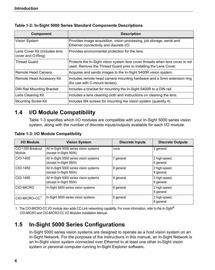
1.4 I/O Module CompatibilityTable 1-3 specifies which I/O modules are compatible with your In-Sight 5000 series vision system, along with the number of discrete inputs/outputs available for each I/O module.
Table 1-3: I/O Module Compatibility
I/O Module Vision System Discrete Inputs Discrete Outputs
1. The CIO-MICRO-CC I/O module also adds CC-Link networking capability. For more information, refer to the In-Sight®
CIO-MICRO and CIO-MICRO-CC I/O Modules Installation Manual.
1.5 In-Sight 5000 Series ConfigurationsIn-Sight 5000 series vision systems are designed to operate as a host vision system on an In-Sight Network. For the purposes of the instructions in this manual, an In-Sight Network is an In-Sight vision system connected over Ethernet to at least one other In-Sight vision system or personal computer running In-Sight Explorer software.
Table 1-2: In-Sight 5000 Series Standard Components Descriptions
Component Description
Vision System Provides image acquisition, vision processing, job storage, serial and Ethernet connectivity and discrete I/O.
Lens Cover Kit (includes lens cover and O-Ring)
Provides environmental protection for the lens.
Thread Guard Protects the In-Sight vision system lens cover threads when lens cover is not used. Remove the Thread Guard prior to installing the Lens Cover.
Remote Head Camera Acquires and sends images to the In-Sight 5400R vision system.
Remote Head Accessory Kit Includes remote head camera mounting hardware and a 5mm extension ring (for use with C-mount lenses).
DIN Rail Mounting Bracket Includes a bracket for mounting the In-Sight 5400R to a DIN rail.
Lens Cleaning Kit Includes a lens cleaning cloth and instructions on cleaning the lens.
Mounting Screw Kit Includes M4 screws for mounting the vision system (quantity 4).
CIO-1350 Breakout Module
All In-Sight 5000 series vision systems (except In-Sight 5604)
none 2 general
CIO-1400 All In-Sight 5000 series vision systems (except In-Sight 5604)
7 general 2 high-speed, 6 general
CIO-1450 All In-Sight 5000 series vision systems (except In-Sight 5604)
8 general 2 high-speed, 8 general
CIO-1460 All In-Sight 5000 series vision systems (except In-Sight 5604)
8 general 2 high-speed, 8 general
CIO-MICRO In-Sight 5600 series vision systems 8 general 2 high-speed, 8 general
CIO-MICRO-CC1 In-Sight 5600 series vision systems 8 general 2 high-speed, 8 general
4
In-Sight® 5000 Series Vision System Installation Manual
These configurations may require additional components, such as an Ethernet switch. Many optional components may be purchased directly from Cognex. A complete catalog of In-Sight products and accessories is available on the Cognex web site at: http://www.cognex.com.
These vision systems may be used in several possible network configurations. For each configuration, the vision system is managed using “jobs” in the In-Sight Explorer software, which also provides a remote display for that vision system. The jobs that can be stored are limited to the amount of local storage available on the vision system. Jobs that exceed this limit, and all image files, can be stored on the local PC.
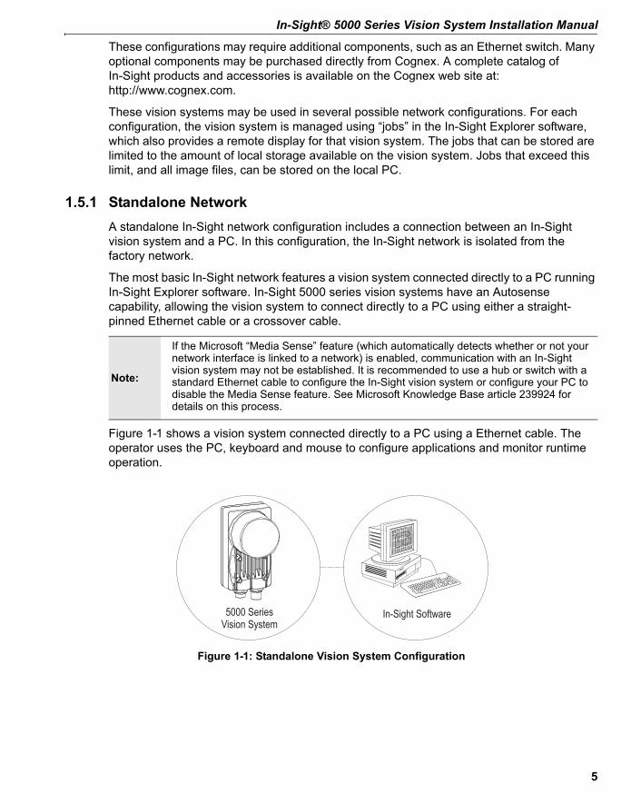
Figure 1-1: Standalone Vision System Configuration
1.5.1 Standalone NetworkA standalone In-Sight network configuration includes a connection between an In-Sight vision system and a PC. In this configuration, the In-Sight network is isolated from the factory network.
The most basic In-Sight network features a vision system connected directly to a PC running In-Sight Explorer software. In-Sight 5000 series vision systems have an Autosense capability, allowing the vision system to connect directly to a PC using either a straight-pinned Ethernet cable or a crossover cable.
Figure 1-1 shows a vision system connected directly to a PC using a Ethernet cable. The operator uses the PC, keyboard and mouse to configure applications and monitor runtime operation.
In-Sight Software5000 SeriesVision System
Note:
If the Microsoft “Media Sense” feature (which automatically detects whether or not your network interface is linked to a network) is enabled, communication with an In-Sight vision system may not be established. It is recommended to use a hub or switch with a standard Ethernet cable to configure the In-Sight vision system or configure your PC to disable the Media Sense feature. See Microsoft Knowledge Base article 239924 for details on this process.
5
Introduction
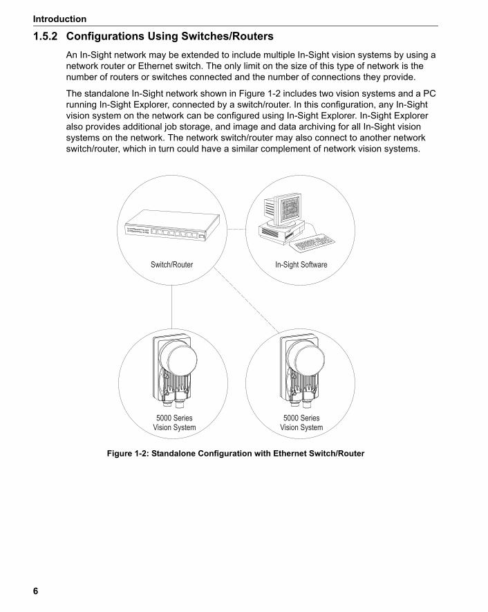
Figure 1-2: Standalone Configuration with Ethernet Switch/Router
1.5.2 Configurations Using Switches/RoutersAn In-Sight network may be extended to include multiple In-Sight vision systems by using a network router or Ethernet switch. The only limit on the size of this type of network is the number of routers or switches connected and the number of connections they provide.
The standalone In-Sight network shown in Figure 1-2 includes two vision systems and a PC running In-Sight Explorer, connected by a switch/router. In this configuration, any In-Sight vision system on the network can be configured using In-Sight Explorer. In-Sight Explorer also provides additional job storage, and image and data archiving for all In-Sight vision systems on the network. The network switch/router may also connect to another network switch/router, which in turn could have a similar complement of network vision systems.
5000 SeriesVision System
Switch/Router In-Sight Software
5000 SeriesVision System
6

In-Sight® 5000 Series Vision System Installation Manual
Figure 1-3: Factory Floor Network Installation
1.5.3 Adding an In-Sight Network to the Factory NetworkMultiple In-Sight Networks may be connected to the larger, factory network, combining to create an In-Sight network of virtually unlimited size. Connecting an In-Sight network to the factory network allows real-time production data to be accessed remotely from any PC workstation with network access. For networks that cover large physical areas, a PC running In-Sight Explorer located on each In-Sight network provides local job configuration and image display for all In-Sight vision systems.
As in the example in Figure 1-2, the In-Sight network shown in Figure 1-3 includes a vision system and a PC running In-Sight Explorer, connected to the same network switch/router. However, the switch/router for the In-Sight network is now connected to the factory network through another switch/router, which in turn may host connections to additional In-Sight networks.
Switch/Router
In-Sight Software
5000 SeriesVision System
In-Sight Software
Switch/Router
7

Introduction
8
2 Installing the Vision System
In This Section...2.1 Connecting the In-Sight 5000 Series Vision System ................ 92.2 Connecting the In-Sight 5000 Series Components................. 10
2.1 Connecting the In-Sight 5000 Series Vision SystemThis section describes the connection of the In-Sight 5000 series vision system to its standard and optional components. For a complete list of options and accessories, contact your local Cognex sales representative.
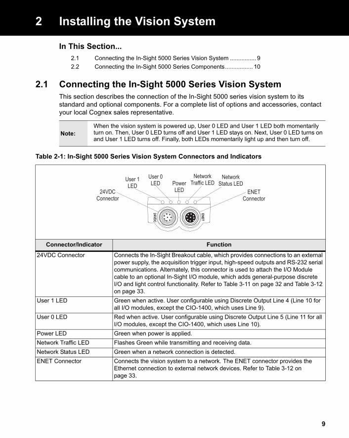
Table 2-1: In-Sight 5000 Series Vision System Connectors and Indicators
ENET
24VDCENET
Connector
NetworkStatus LED
NetworkTraffic LEDPower
LED
User 0LEDUser 1
LED24VDC
Connector
Connector/Indicator Function
24VDC Connector Connects the In-Sight Breakout cable, which provides connections to an external power supply, the acquisition trigger input, high-speed outputs and RS-232 serial communications. Alternately, this connector is used to attach the I/O Module cable to an optional In-Sight I/O module, which adds general-purpose discrete I/O and light control functionality. Refer to Table 3-11 on page 32 and Table 3-12 on page 33.
User 1 LED Green when active. User configurable using Discrete Output Line 4 (Line 10 for all I/O modules, except the CIO-1400, which uses Line 9).
User 0 LED Red when active. User configurable using Discrete Output Line 5 (Line 11 for all I/O modules, except the CIO-1400, which uses Line 10).
Power LED Green when power is applied.Network Traffic LED Flashes Green while transmitting and receiving data.Network Status LED Green when a network connection is detected.ENET Connector Connects the vision system to a network. The ENET connector provides the
Ethernet connection to external network devices. Refer to Table 3-12 on page 33.
Note:When the vision system is powered up, User 0 LED and User 1 LED both momentarily turn on. Then, User 0 LED turns off and User 1 LED stays on. Next, User 0 LED turns on and User 1 LED turns off. Finally, both LEDs momentarily light up and then turn off.
9

Installing the Vision System
2.2 Connecting the In-Sight 5000 Series Components
Figure 2-1: Install the Lens
2.2.1 Install the LensInstalling a lens allows you to see the vision system acquire live video images. The exact lens focal length needed depends on the working distance and the field of view required for your machine vision application.
In-Sight 5000 Series Vision System (except In-Sight 5604 and 5400R):
ENET
24VDC
1. After removing the protective lens cap, attach a C-Mount lens to the vision system (Figure 2-1).
10
In-Sight® 5000 Series Vision System Installation Manual
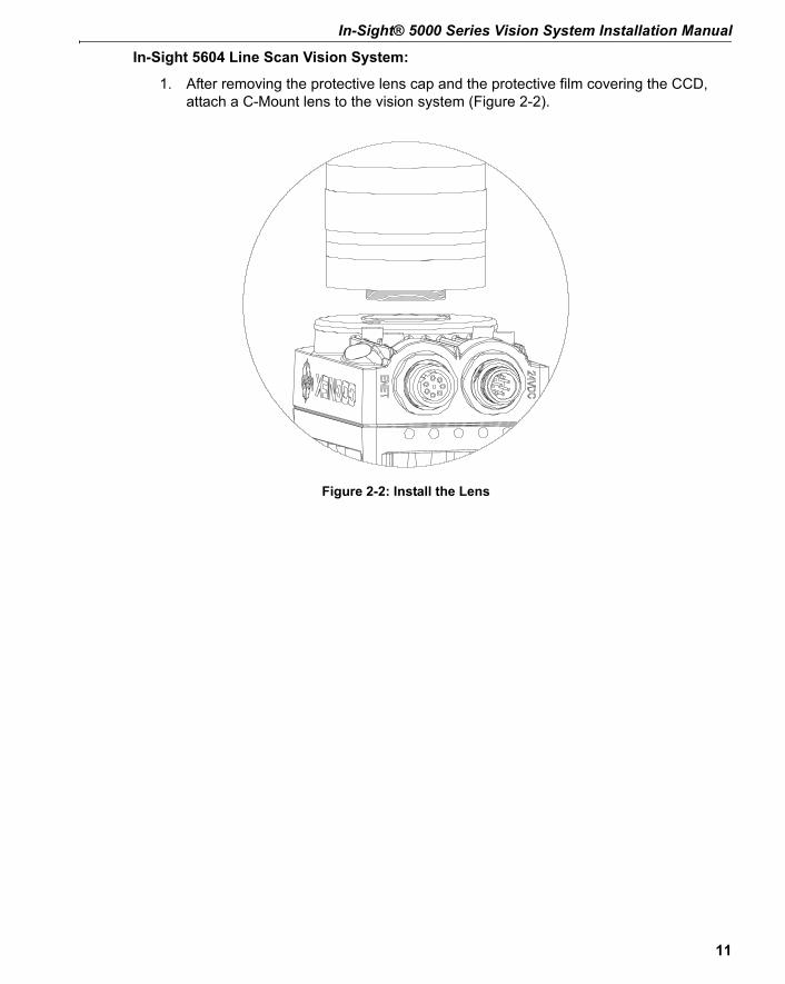
Figure 2-2: Install the Lens
In-Sight 5604 Line Scan Vision System:
1. After removing the protective lens cap and the protective film covering the CCD, attach a C-Mount lens to the vision system (Figure 2-2).
11

Installing the Vision System
Figure 2-3: Install the Lens
In-Sight 5400R Remote Head Vision System:
1. Attach a CS-Mount or C-Mount (with 5mm extension ring) lens to the remote head camera (Figure 2-3).
12

In-Sight® 5000 Series Vision System Installation Manual
Figure 2-4: CAM0 Connection
2.2.2 Attach the Remote Head Camera cable1. Attach the Camera cable’s female M12 connector to the remote head camera's
male M12 connector.2. Attach the Camera cable’s male M12 connector to the vision system's CAM0
connector (Figure 2-4).
Notes:• Cables are sold separately.
• Refer to Appendix A for instructions on mounting the remote head camera.
!Caution:
• Remove power from the vision system before connecting or disconnecting the remote head camera. “Hot plugging” the remote head camera can damage the In-Sight vision system and/or remote head camera.
• The cable connectors are “keyed” to fit the connectors on the vision system; do not force the connection or damage may occur.
13
Installing the Vision System
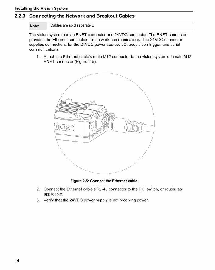
Figure 2-5: Connect the Ethernet cable
2.2.3 Connecting the Network and Breakout Cables
The vision system has an ENET connector and 24VDC connector. The ENET connector provides the Ethernet connection for network communications. The 24VDC connector supplies connections for the 24VDC power source, I/O, acquisition trigger, and serial communications.
1. Attach the Ethernet cable’s male M12 connector to the vision system's female M12 ENET connector (Figure 2-5).
2. Connect the Ethernet cable’s RJ-45 connector to the PC, switch, or router, as applicable.
3. Verify that the 24VDC power supply is not receiving power.
Note: Cables are sold separately.
14
In-Sight® 5000 Series Vision System Installation Manual
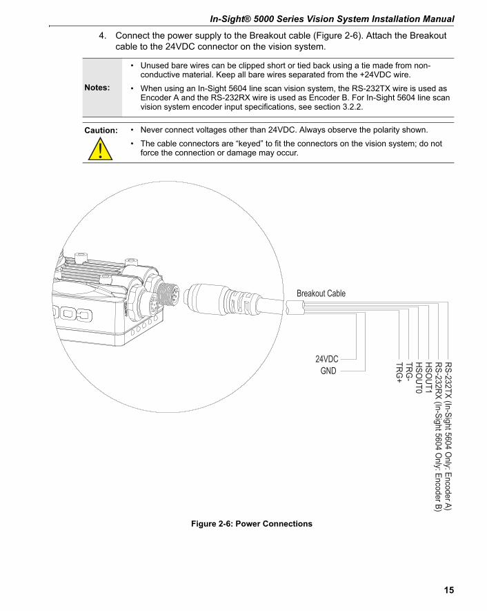
Figure 2-6: Power Connections
4. Connect the power supply to the Breakout cable (Figure 2-6). Attach the Breakout cable to the 24VDC connector on the vision system.
Notes:
• Unused bare wires can be clipped short or tied back using a tie made from non-conductive material. Keep all bare wires separated from the +24VDC wire.
• When using an In-Sight 5604 line scan vision system, the RS-232TX wire is used as Encoder A and the RS-232RX wire is used as Encoder B. For In-Sight 5604 line scan vision system encoder input specifications, see section 3.2.2.
!Caution: • Never connect voltages other than 24VDC. Always observe the polarity shown.
• The cable connectors are “keyed” to fit the connectors on the vision system; do not force the connection or damage may occur.
RS-232TX (In-Sight 5604 Only: Encoder A)
RS-232RX (In-Sight 5604 Only: Encoder B)
HSOUT1
HSOUT0
TRG-
TRG+
24VDC
Breakout Cable
GND
15

Installing the Vision System
16
3 Specifications
In This Section…3.1 General Specifications ............................................................173.2 I/O Specifications ....................................................................283.3 In-Sight Dimensional Drawings............................................... 36
3.1 General SpecificationsThe following sections list general specifications for the In-Sight 5000 series vision systems.
Note:
The In-Sight 5000 series includes vision systems that support ID tools only (ID Readers). ID Readers can be identified by the In-Sight 5000 series model number. An In-Sight 5000 series model number with a “1” in the third digit (e.g. 5110) is an ID Reader. An ID Reader has the same hardware as the corresponding general purpose vision system.
17
Specifications
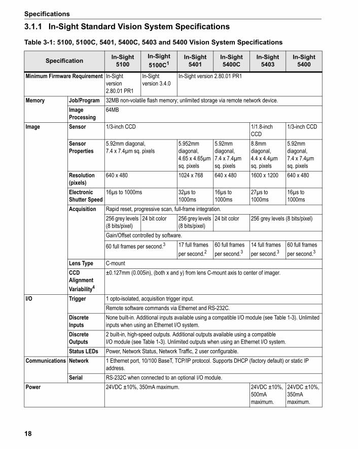
3.1.1 In-Sight Standard Vision System Specifications
Table 3-1: 5100, 5100C, 5401, 5400C, 5403 and 5400 Vision System Specifications
Specification In-Sight 5100
In-Sight 5100C1
In-Sight 5401
In-Sight 5400C
In-Sight 5403
In-Sight 5400
Minimum Firmware Requirement In-Sight version 2.80.01 PR1
In-Sight version 3.4.0
In-Sight version 2.80.01 PR1
Memory Job/Program 32MB non-volatile flash memory; unlimited storage via remote network device.Image Processing
64MB
Image Sensor 1/3-inch CCD 1/1.8-inch CCD
1/3-inch CCD
Sensor Properties
5.92mm diagonal, 7.4 x 7.4µm sq. pixels
5.952mm diagonal, 4.65 x 4.65µm sq. pixels
5.92mm diagonal, 7.4 x 7.4µm sq. pixels
8.8mmdiagonal, 4.4 x 4.4µm sq. pixels
5.92mm diagonal, 7.4 x 7.4µm sq. pixels
Resolution (pixels)
640 x 480 1024 x 768 640 x 480 1600 x 1200 640 x 480
Electronic Shutter Speed
16µs to 1000ms 32µs to 1000ms
16µs to 1000ms
27µs to 1000ms
16µs to 1000ms
Acquisition Rapid reset, progressive scan, full-frame integration.256 grey levels (8 bits/pixel)
24 bit color 256 grey levels (8 bits/pixel)
24 bit color 256 grey levels (8 bits/pixel)
Gain/Offset controlled by software.
60 full frames per second.3 17 full frames per second.2
60 full frames per second.3
14 full frames per second.3
60 full frames per second.3
Lens Type C-mountCCD Alignment Variability4
±0.127mm (0.005in), (both x and y) from lens C-mount axis to center of imager.
I/O Trigger 1 opto-isolated, acquisition trigger input.Remote software commands via Ethernet and RS-232C.
Discrete Inputs
None built-in. Additional inputs available using a compatible I/O module (see Table 1-3). Unlimited inputs when using an Ethernet I/O system.
Discrete Outputs
2 built-in, high-speed outputs. Additional outputs available using a compatible I/O module (see Table 1-3). Unlimited outputs when using an Ethernet I/O system.
Status LEDs Power, Network Status, Network Traffic, 2 user configurable.Communications Network 1 Ethernet port, 10/100 BaseT, TCP/IP protocol. Supports DHCP (factory default) or static IP
address.Serial RS-232C when connected to an optional I/O module.
Power 24VDC ±10%, 350mA maximum. 24VDC ±10%, 500mA maximum.
24VDC ±10%, 350mA maximum.
18
In-Sight® 5000 Series Vision System Installation Manual
1. In-Sight 5100C vision systems with P/N 800-5837-1 are compatible with firmware version 2.65.00 and higher. In-Sight 5100C vision systems with P/N 800-5837-4 are compatible with firmware version 3.4.0 and higher. To locate the Part Number, refer to the Part Number label on the back of your vision system.
2. Maximum frames per second are job dependent and based on an 8ms exposure and a full image frame capture.3. Maximum frames per second are job dependent and based on the minimum exposure for a full image frame capture.4. Expected variability in the physical position of the CCD, from vision system-to-vision system. This equates to
~ ±17 pixels on a 640 x 480 resolution CCD and ~ ±29 pixels on a 1600 x 1200 resolution CCD.
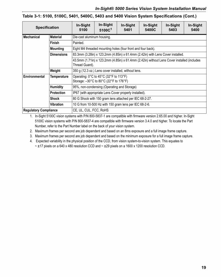
Mechanical Material Die-cast aluminum housing.Finish Painted.Mounting Eight M4 threaded mounting holes (four front and four back).Dimensions 83.3mm (3.28in) x 123.2mm (4.85in) x 61.4mm (2.42in) with Lens Cover installed.
43.5mm (1.71in) x 123.2mm (4.85in) x 61.4mm (2.42in) without Lens Cover installed (includes Thread Guard).
Weight 350 g (12.3 oz.) Lens cover installed, without lens.Environmental Temperature Operating: 0°C to 45°C (32°F to 113°F)
Storage: –30°C to 80°C (22°F to 176°F)Humidity 95%, non-condensing (Operating and Storage)Protection IP67 (with appropriate Lens Cover properly installed).Shock 80 G Shock with 150 gram lens attached per IEC 68-2-27.Vibration 10 G from 10-500 Hz with 150 gram lens per IEC 68-2-6.
Regulatory Compliance CE, UL, CUL, FCC, RoHS
Table 3-1: 5100, 5100C, 5401, 5400C, 5403 and 5400 Vision System Specifications (Cont.)
Specification In-Sight 5100
In-Sight 5100C1
In-Sight 5401
In-Sight 5400C
In-Sight 5403
In-Sight 5400
19
Specifications
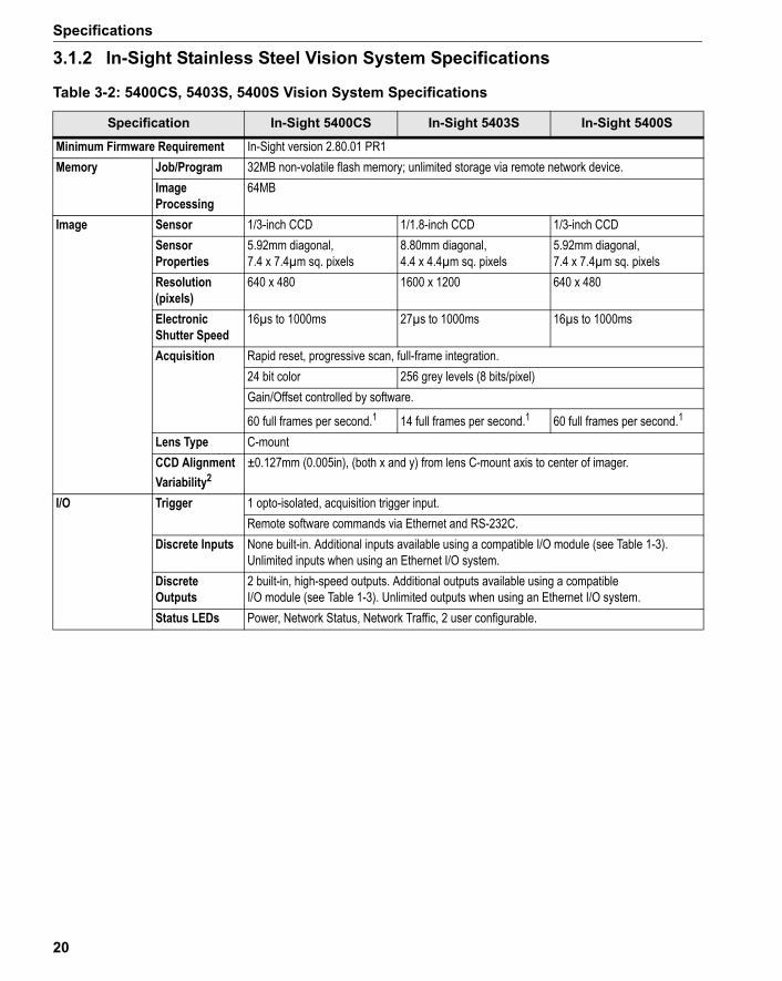
3.1.2 In-Sight Stainless Steel Vision System Specifications
Table 3-2: 5400CS, 5403S, 5400S Vision System Specifications
Specification In-Sight 5400CS In-Sight 5403S In-Sight 5400S
Minimum Firmware Requirement In-Sight version 2.80.01 PR1Memory Job/Program 32MB non-volatile flash memory; unlimited storage via remote network device.
Image Processing
64MB
Image Sensor 1/3-inch CCD 1/1.8-inch CCD 1/3-inch CCDSensor Properties
5.92mm diagonal, 7.4 x 7.4µm sq. pixels
8.80mm diagonal, 4.4 x 4.4µm sq. pixels
5.92mm diagonal, 7.4 x 7.4µm sq. pixels
Resolution (pixels)
640 x 480 1600 x 1200 640 x 480
Electronic Shutter Speed
16µs to 1000ms 27µs to 1000ms 16µs to 1000ms
Acquisition Rapid reset, progressive scan, full-frame integration.24 bit color 256 grey levels (8 bits/pixel)Gain/Offset controlled by software.
60 full frames per second.1 14 full frames per second.1 60 full frames per second.1
Lens Type C-mount CCD Alignment Variability2
±0.127mm (0.005in), (both x and y) from lens C-mount axis to center of imager.
I/O Trigger 1 opto-isolated, acquisition trigger input.Remote software commands via Ethernet and RS-232C.
Discrete Inputs None built-in. Additional inputs available using a compatible I/O module (see Table 1-3). Unlimited inputs when using an Ethernet I/O system.
Discrete Outputs
2 built-in, high-speed outputs. Additional outputs available using a compatible I/O module (see Table 1-3). Unlimited outputs when using an Ethernet I/O system.
Status LEDs Power, Network Status, Network Traffic, 2 user configurable.
20

In-Sight® 5000 Series Vision System Installation Manual
1. Maximum frames per second are job dependent and based on the minimum exposure for a full image frame capture.2. Expected variability in the physical position of the CCD, from vision system-to-vision system. This equates to ~ ±17 pixels on
a 640 x 480 resolution CCD and ~ ±29 pixels on a 1600 x 1200 resolution CCD.
Communications Network 1 Ethernet port, 10/100 BaseT, TCP/IP protocol. Supports DHCP (factory default) or static IP address.
Serial RS-232C when connected to an optional I/O module.Power 24VDC ±10%, 350mA
maximum.24VDC ±10%, 500mA maximum.
24VDC ±10%, 350mA maximum.
Mechanical Material ASTM 316L Stainless Steel.Finish Electropolish Passivated.Mounting Four M4 threaded mounting holes on back of vision system.Dimensions 90.6mm (3.57in) x 124.0mm (4.88in) x 61.4mm (2.42in) with Lens Cover installed.
43.5mm (1.71in) x 124.0mm (4.88in) x 61.4mm (2.42in) without Lens Cover installed.Weight 907 g (32.0 oz.) Lens cover installed, without lens.
Environmental Temperature Operating: 0°C to 45°C (32°F to 113°F)Storage: –30°C to 80°C (22°F to 176°F)
Humidity 95%, non-condensing (Operating and Storage)Protection IP68 (with appropriate Lens Cover properly installed).Shock 80 G Shock with 150 gram lens attached per IEC 68-2-27.Vibration 10 G from 10-500 Hz with 150 gram lens per IEC 68-2-6.
Regulatory Compliance CE, UL, CUL, FCC, RoHS
Table 3-2: 5400CS, 5403S, 5400S Vision System Specifications (Cont.)
Specification In-Sight 5400CS In-Sight 5403S In-Sight 5400S
21

Specifications
3.1.3 In-Sight Remote Head Vision System Specifications
Table 3-3: 5400R Vision System Specifications
Specification In-Sight 5400R
Minimum Firmware Requirement In-Sight version 3.2.0Memory Job/Program 32MB non-volatile flash memory; unlimited storage via remote network device.
Image Processing
64MB
I/O Trigger 1 opto-isolated, acquisition trigger input.Remote software commands via Ethernet and RS-232C.
Discrete Inputs None built-in. Additional inputs available using a compatible I/O module (see Table 1-3). Unlimited inputs when using an Ethernet I/O system.
Discrete Outputs 2 built-in, high-speed outputs. Additional outputs available using a compatible I/O module (see Table 1-3). Unlimited outputs when using an Ethernet I/O system.
Status LEDs Power, Network Status, Network Traffic, 2 user configurable.Communications Network 1 Ethernet port, 10/100 BaseT, TCP/IP protocol. Supports DHCP (factory default)
or static IP address.Serial RS-232C when connected to an optional I/O module.
Power 24VDC ±10%, 250mA maximum.Mechanical Material Die-cast aluminum housing.
Finish Painted.Mounting Four M4 threaded mounting holes on back of vision system.Dimensions 34.0mm (1.34in) x 136.0mm (5.35in) x 61.4mm (2.42in)Weight 295g (10.4 oz.)
Environmental Temperature Operating: 0°C to 55°C (32°F to 131°F)Storage: –30°C to 80°C (22°F to 176°F)
Humidity 95%, non-condensing (Operating and Storage)Protection IP67Shock 80 G shock per IEC 68-2-27.Vibration 10 G from 10-500 Hz per IEC 68-2-6.
Regulatory Compliance CE, UL, CUL, FCC, RoHS
1. Maximum frames per second is job dependent and based on an 8ms exposure and a full image frame capture.2. Expected variability in the physical position of the CCD, from vision system-to-vision system. This equates to ~ ±17 pixels
on a 640 x 480 resolution CCD.
22

In-Sight® 5000 Series Vision System Installation Manual
Table 3-4: Remote Head Camera Specifications
Specification Remote Head Camera
Image Sensor 1/3-inch CCDSensor Properties 5.92mm diagonal, 7.4 x 7.4µm sq. pixels.Resolution (pixels) 640 x 480Electronic Shutter Speed 25µs to 1000ms (except value selected must be in increments of 50µs i.e.,
25µs, 75µs, 125µs, etc.).Acquisition Rapid reset, progressive scan (supports partial scan), full-frame integration.
256 grey levels (8 bits/pixel).Gain controlled by software.
31 full frames per second.1
Lens Type CS-mount and C-mount (with 5mm extension, included).
CCD Alignment Variability2 ±0.254mm (0.01in), (both x and y) from lens C-mount axis to center of imager.
Mechanical Material/Finish Anodized, aluminum housing.Mounting Three M3 threaded holes.Dimensions 32.0mm (1.26in) diameter, 50.6mm (1.99in) length Weight 68 g (2.4 oz.) without lens
Environmental Temperature Operating: 0°C to 45°C (32°F to 113°F)Storage: –30°C to 80°C (22°F to 176°F)
Humidity 95% non-condensing (Operating and Storage).Protection For environments where protection is required, use the optional protective
Remote Head Camera Enclosure, Cognex P/N 800-5783-1.Shock 80 G Shock with 150 g or lighter lens per IEC 68-2-27. Remote head properly
mounted using Cognex mounting bracket with vibration dampener tube.Vibration 10 G from 10-500Hz Vibration per IEC 68-2-6 with 150 g or lighter lens attached.
Remote head properly mounted using Cognex mounting bracket with vibration damper tube.
Regulatory Compliance CE, UL, CUL, FCC, RoHS
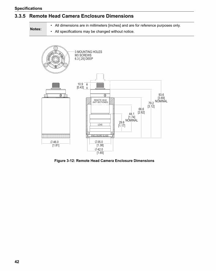
Table 3-5: Remote Head Camera Enclosure Specifications
Specification Remote Head Camera Enclosure
Mechanical Material/Finish Anodized aluminum housing with glass window.Stainless steel housing with polycarbonate window (optional).
Mounting Three M3 threaded holes.Dimensions Without remote head camera: 66.6mm (2.62in) high x 46.0mm (1.81in) diameter.
Nominal height with remote head camera: 79.2mm (3.12 in) to 93.6mm (3.69 in).Weight 136.1 g (4.8 oz.), without remote head camera.Protection IP67
23
Specifications
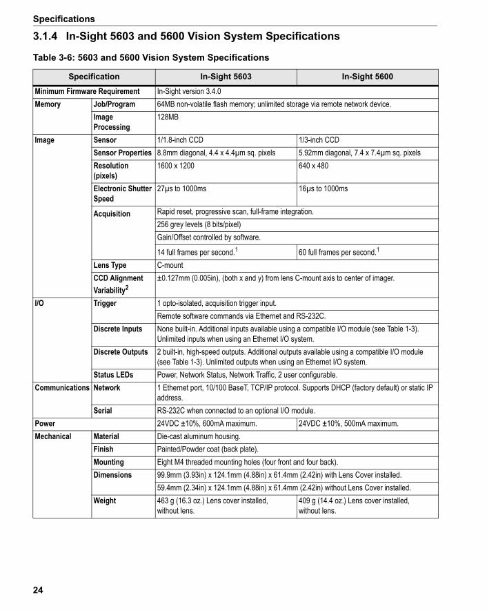
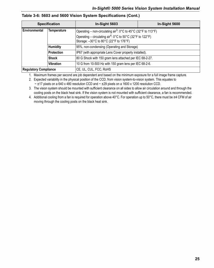
3.1.4 In-Sight 5603 and 5600 Vision System Specifications
Table 3-6: 5603 and 5600 Vision System Specifications
Specification In-Sight 5603 In-Sight 5600
Minimum Firmware Requirement In-Sight version 3.4.0Memory Job/Program 64MB non-volatile flash memory; unlimited storage via remote network device.
Image Processing
128MB
Image Sensor 1/1.8-inch CCD 1/3-inch CCDSensor Properties 8.8mm diagonal, 4.4 x 4.4µm sq. pixels 5.92mm diagonal, 7.4 x 7.4µm sq. pixelsResolution (pixels)
1600 x 1200 640 x 480
Electronic Shutter Speed
27µs to 1000ms 16µs to 1000ms
Acquisition Rapid reset, progressive scan, full-frame integration.256 grey levels (8 bits/pixel)Gain/Offset controlled by software.
14 full frames per second.1 60 full frames per second.1
Lens Type C-mountCCD Alignment Variability2
±0.127mm (0.005in), (both x and y) from lens C-mount axis to center of imager.
I/O Trigger 1 opto-isolated, acquisition trigger input.Remote software commands via Ethernet and RS-232C.
Discrete Inputs None built-in. Additional inputs available using a compatible I/O module (see Table 1-3). Unlimited inputs when using an Ethernet I/O system.
Discrete Outputs 2 built-in, high-speed outputs. Additional outputs available using a compatible I/O module (see Table 1-3). Unlimited outputs when using an Ethernet I/O system.
Status LEDs Power, Network Status, Network Traffic, 2 user configurable.Communications Network 1 Ethernet port, 10/100 BaseT, TCP/IP protocol. Supports DHCP (factory default) or static IP
address.Serial RS-232C when connected to an optional I/O module.
Power 24VDC ±10%, 600mA maximum. 24VDC ±10%, 500mA maximum.Mechanical Material Die-cast aluminum housing.
Finish Painted/Powder coat (back plate).Mounting Eight M4 threaded mounting holes (four front and four back).Dimensions 99.9mm (3.93in) x 124.1mm (4.88in) x 61.4mm (2.42in) with Lens Cover installed.
59.4mm (2.34in) x 124.1mm (4.88in) x 61.4mm (2.42in) without Lens Cover installed.Weight 463 g (16.3 oz.) Lens cover installed,
without lens.409 g (14.4 oz.) Lens cover installed, without lens.
24
In-Sight® 5000 Series Vision System Installation Manual
1. Maximum frames per second are job dependent and based on the minimum exposure for a full image frame capture.2. Expected variability in the physical position of the CCD, from vision system-to-vision system. This equates to
~ ±17 pixels on a 640 x 480 resolution CCD and ~ ±29 pixels on a 1600 x 1200 resolution CCD.3. The vision system should be mounted with sufficient clearance on all sides to allow air circulation around and through the
cooling posts on the black heat sink. If the vision system is not mounted with sufficient clearance, a fan is recommended.4. Additional cooling from a fan is required for operation above 40°C. For operation up to 50°C, there must be ≥4 CFM of air
moving through the cooling posts on the black heat sink.
Environmental Temperature Operating – non-circulating air3: 0°C to 45°C (32°F to 113°F) Operating – circulating air4: 0°C to 50°C (32°F to 122°F)Storage: –30°C to 80°C (22°F to 176°F)
Humidity 95%, non-condensing (Operating and Storage)Protection IP67 (with appropriate Lens Cover properly installed).Shock 80 G Shock with 150 gram lens attached per IEC 68-2-27.Vibration 10 G from 10-500 Hz with 150 gram lens per IEC 68-2-6.
Regulatory Compliance CE, UL, CUL, FCC, RoHS
Table 3-6: 5603 and 5600 Vision System Specifications (Cont.)
Specification In-Sight 5603 In-Sight 5600
25

Specifications
3.1.5 In-Sight 5604 Line Scan Vision System Specifications
Table 3-7: 5604 Vision System Specifications
Specification In-Sight 5604
Minimum Firmware Requirement In-Sight version 4.3.0Memory Job/Program 64MB non-volatile flash memory; unlimited storage via remote network device.
Image Processing
128MB
Image Sensor 1-inch CCDSensor Properties 14.3 mm x 14µm active area, 14µm x 14µm sq. pixels.Resolution (pixels)
1024 x 1 (CCD); 1024 x 2048 (up to 2048 lines for full resolution image).
Acquisition Line Scan integration.256 grey levels (8 bits/pixel).Gain/Offset controlled by software.
44K lines per second.1
Lens Type C-mountCCD Alignment Variability2
±0.127mm (0.005in), (both x and y) from lens C-mount axis to center of imager.
I/O Trigger 1 opto-isolated, acquisition trigger input.Remote software commands via Ethernet and RS-232C.
Discrete Inputs None built-in. Additional inputs available using a compatible I/O module (see Table 1-3). Unlimited inputs when using an Ethernet I/O system.
Discrete Outputs 2 built-in, high-speed outputs. Additional outputs available using a compatible I/O module (see Table 1-3). Unlimited outputs when using an Ethernet I/O system.
Encoder Inputs 2 built-in, encoder inputs for use with a 24V signal.Status LEDs Power, Network Status, Network Traffic, 2 user configurable.
Communications Network 1 Ethernet port, 10/100 BaseT, TCP/IP protocol. Supports DHCP (factory default) or static IP address.
Serial RS-232C when connected to an optional CIO-MICRO OR CIO-MICRO-CC I/O module.Power 24VDC ±10%, 350mA maximum.Mechanical Material Die-cast aluminum housing.
Finish Painted/Powder coat (back plate).Mounting Eight M4 threaded mounting holes (four front and four back).Dimensions 53.2mm (1.50in) x 124.1mm (4.88in) x 61.4mm (2.42in)Weight 454 g (16 oz.) protective lens cap installed, without lens.
Environmental Temperature Operating – non-circulating air3: 0°C to 45°C (32°F to 113°F) Operating – circulating air4: 0°C to 50°C (32°F to 122°F)Storage: –30°C to 80°C (22°F to 176°F)
Humidity 95%, non-condensing (Operating and Storage)Protection For environments where protection is required, use an optional protective enclosure.Shock 80 G Shock with 150 gram lens attached per IEC 68-2-27.Vibration 10 G from 10-500 Hz with 150 gram lens per IEC 68-2-6.
26

In-Sight® 5000 Series Vision System Installation Manual
1. Maximum lines per second are based on the minimum exposure.2. Expected variability in the physical position of the CCD, from vision system-to-vision system. This equates to
~ ±8 pixels on a 2024 x 1 resolution CCD.3. The vision system should be mounted with sufficient clearance on all sides to allow air circulation around and through the
cooling posts on the black heat sink. If the vision system is not mounted with sufficient clearance, a fan is recommended.4. Additional cooling from a fan is required for operation above 40°C. For operation up to 50°C, there must be ≥4 CFM of air
moving through the cooling posts on the black heat sink.
Regulatory Compliance CE, UL, CUL, FCC, RoHS
Table 3-7: 5604 Vision System Specifications (Cont.)
Specification In-Sight 5604
27
Specifications
3.2 I/O SpecificationsCable and connector specifications and connection examples for the Acquisition Trigger input, encoder inputs (In-Sight 5604 only) and the high-speed outputs are provided in the following sections.
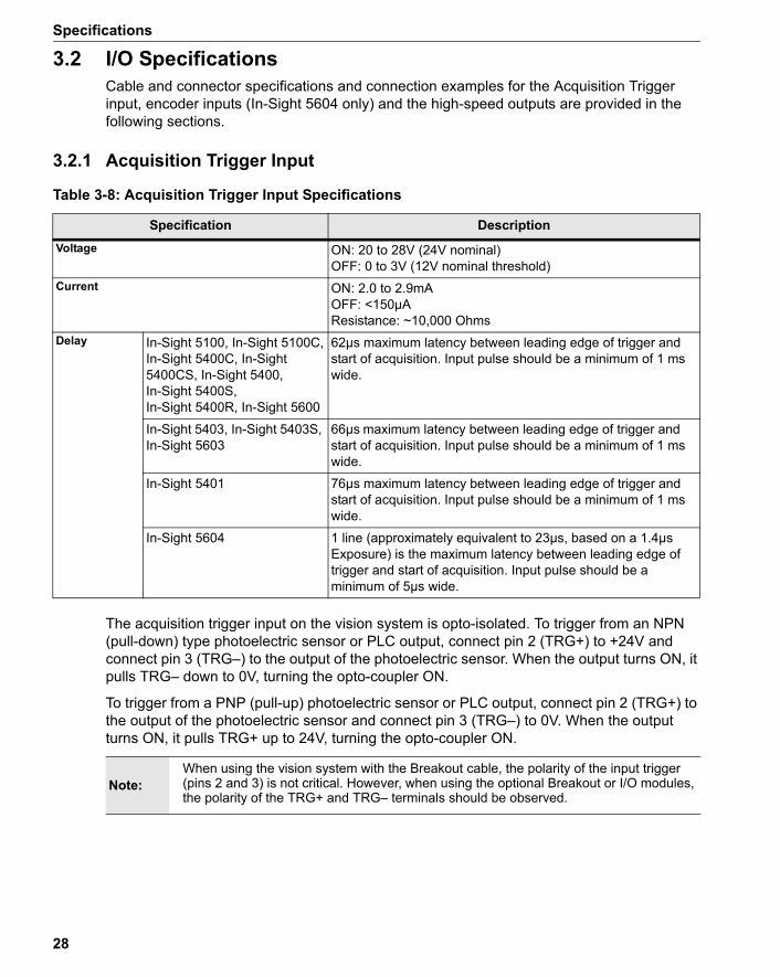
3.2.1 Acquisition Trigger Input
Table 3-8: Acquisition Trigger Input Specifications
Specification DescriptionVoltage ON: 20 to 28V (24V nominal)
OFF: 0 to 3V (12V nominal threshold)Current ON: 2.0 to 2.9mA
OFF: <150µAResistance: ~10,000 Ohms
Delay In-Sight 5100, In-Sight 5100C,In-Sight 5400C, In-Sight 5400CS, In-Sight 5400, In-Sight 5400S, In-Sight 5400R, In-Sight 5600
62µs maximum latency between leading edge of trigger and start of acquisition. Input pulse should be a minimum of 1 ms wide.
In-Sight 5403, In-Sight 5403S, In-Sight 5603
66µs maximum latency between leading edge of trigger and start of acquisition. Input pulse should be a minimum of 1 ms wide.
In-Sight 5401 76µs maximum latency between leading edge of trigger and start of acquisition. Input pulse should be a minimum of 1 ms wide.
In-Sight 5604 1 line (approximately equivalent to 23µs, based on a 1.4µs Exposure) is the maximum latency between leading edge of trigger and start of acquisition. Input pulse should be a minimum of 5µs wide.
The acquisition trigger input on the vision system is opto-isolated. To trigger from an NPN (pull-down) type photoelectric sensor or PLC output, connect pin 2 (TRG+) to +24V and connect pin 3 (TRG–) to the output of the photoelectric sensor. When the output turns ON, it pulls TRG– down to 0V, turning the opto-coupler ON.
To trigger from a PNP (pull-up) photoelectric sensor or PLC output, connect pin 2 (TRG+) to the output of the photoelectric sensor and connect pin 3 (TRG–) to 0V. When the output turns ON, it pulls TRG+ up to 24V, turning the opto-coupler ON.
Note:When using the vision system with the Breakout cable, the polarity of the input trigger (pins 2 and 3) is not critical. However, when using the optional Breakout or I/O modules, the polarity of the TRG+ and TRG– terminals should be observed.
28

In-Sight® 5000 Series Vision System Installation Manual
Figure 3-1: Acquisition Trigger Input Schematic
Figure 3-2: Connect the Encoder
Table 3-9: Encoder Input Specifications (In-Sight 5604 only)
Specification Description
TRG+
TRG-
4.7K
4.7K
2.2K
28V Max. Across input pins - Transition approx. 12V (Min).
3.2.2 Encoder Inputs (In-Sight 5604 only)Pins 6 and 7 of the Breakout cable (see Table 3-11 on page 32 for cable pin-outs) can be used for communication between the In-Sight 5604 line scan vision system and a single or quadrature encoder. The signal from the encoder must be 24V (other input specifications are listed in Table 3-9)
.
Encoder AEncoder B
HSOUT1HSOUT0
TRG-TRG+
GND24VDC
GND24VDC
Breakout Cable
Power Supply Signal AEncoder
Signal B
Voltage ON: 20 to 28V (24V nominal)OFF: 0 to 3V (9.6V nominal threshold)
Current ON: 84 to 118µAOFF: <11µAResistance: ~233,000 Ohms
29

Specifications
3.2.3 High-Speed OutputsIn-Sight 5000 series vision systems feature two built-in, high-speed outputs.
Table 3-10: High-Speed Output Specifications
Specification Description
Both of the high-speed outputs are NPN (pull-down) lines. The external load should be connected between the output and the positive supply voltage (<28V). The outputs pull down to <0.1V when ON (<1.25V for In-Sight 5604 only), which causes current to flow through the load. When the outputs are OFF, no current flows through the load.
Figure 3-3: High-Speed Output Connection Example 1
Example 1To connect the high-speed outputs to a relay, LED or similar load, connect the negative side of the load to the output and the positive side to +24V. When the output switches on, the negative side of the load is pulled down to 0V, and 24V appears across the load. Use a protection diode for a large inductive load, with the anode connected to the output and the cathode connected to +24V.
RS-232TXRS-232RX
HSOUT1HSOUT0
TRG-TRG+
GND24VDC
Load(Coil, Relay,Pilot Light, etc.)NOT TO EXCEED 200mA
Breakout Cable
Power Supply
Voltage 28V maximum through external load.Current All In-Sight 5000 series
(except In-Sight 5600 series)
200mA maximum sink current.OFF state leakage current 200µA maximum.External load resistance 140 Ohms to 10K Ohms.Each line rated at a maximum 200mA, protected against over-current, short circuit and transients from switching inductive loads. High current inductive loads require external protection diode.
In-Sight 5600 series 100mA maximum sink current.OFF state leakage current 200µA maximum.External load resistance 280 Ohms to 10K Ohms.Each line rated at a maximum 100mA, protected against over-current, short circuit and transients from switching inductive loads. High current inductive loads require external protection diode.
30

In-Sight® 5000 Series Vision System Installation Manual
Figure 3-4: High-Speed Output Connection Example 2
Figure 3-5: High-Speed Output Connection Example 3
Example 2To connect to an NPN-compatible PLC input, connect Output 0 or Output 1 directly to the PLC input. When enabled, the output pulls down the PLC input to 0V.
RS-232TXRS-232RX
HSOUT1HSOUT0
TRG-TRG+
GND24VDC
GND24VDC
Breakout Cable
Power Supply NPN Compatible InputNPN PLC
Example 3High-Speed outputs can also be used with a PNP-compatible PLC input if a pull-up resistor (for example, 2.2k 0.5W) is connected from the output to +24V. In this case, the resistor supplies 24V to the PLC input. The output will pull the voltage down to 0V, turning off the PLC input. This creates an inversion, with the PLC input ON when the In-Sight output is OFF, and vice-versa. Use an external NPN to PNP converter when this inversion is not desired.
2.2K
RS-232TXRS-232RX
HSOUT1HSOUT0
TRG-TRG+
GND24VDC 24VDC
GND
Breakout Cable
Power Supply PNP PLCPNP Compatible Input
31
Specifications
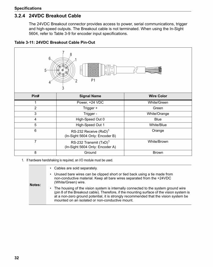
3.2.4 24VDC Breakout CableThe 24VDC Breakout connector provides access to power, serial communications, trigger and high-speed outputs. The Breakout cable is not terminated. When using the In-Sight 5604, refer to Table 3-9 for encoder input specifications.
Table 3-11: 24VDC Breakout Cable Pin-Out
P1
1
23
4
5
67 8
Pin# Signal Name Wire Color
1 Power, +24 VDC White/Green2 Trigger + Green3 Trigger - White/Orange4 High-Speed Out 0 Blue5 High-Speed Out 1 White/Blue6 RS-232 Receive (RxD)1
(In-Sight 5604 Only: Encoder B)Orange
7 RS-232 Transmit (TxD)1(In-Sight 5604 Only: Encoder A)
White/Brown
8 Ground Brown
1. If hardware handshaking is required, an I/O module must be used.
Notes:
• Cables are sold separately.
• Unused bare wires can be clipped short or tied back using a tie made from non-conductive material. Keep all bare wires separated from the +24VDC (White/Green) wire.
• The housing of the vision system is internally connected to the system ground wire (pin 8 of the Breakout cable). Therefore, if the mounting surface of the vision system is at a non-zero ground potential, it is strongly recommended that the vision system be mounted on an isolated or non-conductive mount.
32

In-Sight® 5000 Series Vision System Installation Manual
3.2.5 I/O Module CableThe I/O Module cable is used with the optional I/O module and 1350 Breakout Module (Table 1-3 specifies which I/O modules are compatible with your In-Sight 5000 series vision system). The I/O Module cable connects the vision system directly to the applicable I/O module via the DB15 connector. When the I/O module or 1350 Breakout Module is used, all power and communication lines used by the vision system are connected using the I/O Module cable.
Table 3-12: I/O Module Cable Pin-Out
11
23
4
5
67 8
9
815P1 P2
P1 Pin# Signal Name P2 Pin#
1 Power, +24 VDC 12 Trigger + 23 Trigger - 34 High-Speed Out 0 45 High-Speed Out 1 56 RS-232 Receive (RxD)
(In-Sight 5604 Only: Encoder B)6
7 RS-232 Transmit (TxD)(In-Sight 5604 Only: Encoder A)
7
8 Ground 8
Notes:• Cables are sold separately.
• Refer to your specific I/O module installation manual for more connection information.
33
Specifications
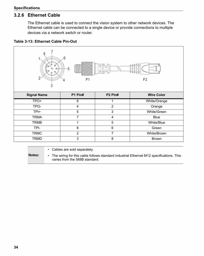
3.2.6 Ethernet CableThe Ethernet cable is used to connect the vision system to other network devices. The Ethernet cable can be connected to a single device or provide connections to multiple devices via a network switch or router.
Table 3-13: Ethernet Cable Pin-Out
P2
1
2
34
5
678
P1
Signal Name P1 Pin# P2 Pin# Wire Color
TPO+ 6 1 White/OrangeTPO- 4 2 OrangeTPI+ 5 3 White/Green
TRMA 7 4 BlueTRMB 1 5 White/BlueTPI- 8 6 Green
TRMC 2 7 White/BrownTRMD 3 8 Brown
Notes:• Cables are sold separately.
• The wiring for this cable follows standard industrial Ethernet M12 specifications. This varies from the 568B standard.
34

In-Sight® 5000 Series Vision System Installation Manual
3.2.7 Camera Cable
The Camera cable connects the remote head camera to the 5400R vision system. The Camera cable provides power and communications to the camera.
Table 3-14: Camera Cable Pin-out
1
23
4
5
67 8
P2P1
1
2
34
5
678
P1 Pin# Signal Name P2 Pin#
1 CTRL+ 12 CTRL- 23 DAT+ 34 +17V 45 -10V 56 DAT- 67 +6V 78 GND 8
Note: Cables are sold separately.
35

Specifications
3.3 In-Sight Dimensional Drawings
Figure 3-6: Standard Vision System Dimensions (With Lens Cover)
3.3.1 5100, 5100C, 5400, 5401, 5400C and 5403 Vision System Dimensions
1.22
21.8 .8620.4 .80
19.5
1.0025.4
25.0
.77
.98
22.4 .88
4.29109.1
83.3 3.28
35.5 1.40
OPTICALAXIS
OPTICALAXIS
OPTICALAXIS
AXISOPTICAL
AXISOPTICAL
OPTICALAXIS
50.0 1.97
.225.6
.235.7
98.0 3.86
4X M4 8.0
61.4 2.42
33.0 1.30
1.4236.0
4.85123.2
31.0
30.0 1.18
4X M4 4.0
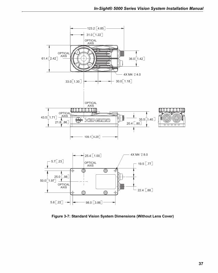
Notes:• All dimensions are in millimeters [inches] and are for reference purposes only.
• All specifications may be changed without notice.
36
In-Sight® 5000 Series Vision System Installation Manual
Figure 3-7: Standard Vision System Dimensions (Without Lens Cover)
AXISOPTICAL
21.8 .86 20.4 .80
25.0 .98
25.4 1.00
19.5 .77
22.4 .88
OPTICALAXIS
109.1 4.29
43.5 1.71 35.5 1.40
AXISOPTICAL
OPTICALAXIS
5.6
.23
1.9750.0
.22
5.7
98.0 3.86
4X M4 8.0
OPTICALAXIS
OPTICALAXIS
31.0 1.22
33.0 1.30 30.0 1.18
4.85123.2
2.4261.4 36.0 1.42
4X M4 4.0
37

Specifications
Figure 3-8: Stainless Steel Vision System Dimensions (With Lens Cover)
3.3.2 5403S, 5400CS and 5400S Vision System Dimensions
19.5
1.0025.4
25.0
.77
.98
22.4 .88
21.8 .86
20.4 .80
OPTICALAXIS
OPTICALAXIS
1.97
.23
5.6 .22
50.0
5.7
98.0 3.86
4X M4 8.0
OPTICALAXIS
OPTICALAXIS
4.29109.0
90.6 3.57
OPTICALAXIS
1.2231.0
61.4 2.42
124.0 4.88
OPTICALAXIS
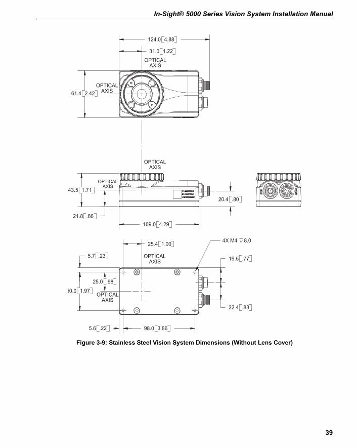
Notes:• All dimensions are in millimeters [inches] and are for reference purposes only.
• All specifications may be changed without notice.
38
In-Sight® 5000 Series Vision System Installation Manual
Figure 3-9: Stainless Steel Vision System Dimensions (Without Lens Cover)
1.0025.4
22.4 .88
19.5
25.0
.77
.98
21.8 .86
20.4 .80
OPTICALAXIS
OPTICALAXIS
1.97
.23
5.6 .22
50.0
5.7
98.0 3.86
4X M4 8.0
OPTICALAXIS
OPTICALAXIS
4.29109.0
43.5 1.71
OPTICALAXIS
1.2231.0
61.4 2.42
124.0 4.88
OPTICALAXIS
39

Specifications
Figure 3-10: 5400R Vision System Dimensions
3.3.3 5400R Vision System Dimensions
136.0[5.35]
109.0[4.29]
61.4[2.42]
34.0[1.34]
20.1[.79]
20.6[.81]
17.5[.69]
4 x M4 7.9 [.31]
98.0[3.86]
50.0[1.97]
5.5 [.22] TYPICAL
ALL SIDES
22.4[.88]
Notes:• All dimensions are in millimeters [inches] and are for reference purposes only.
• All specifications may be changed without notice.
40
In-Sight® 5000 Series Vision System Installation Manual
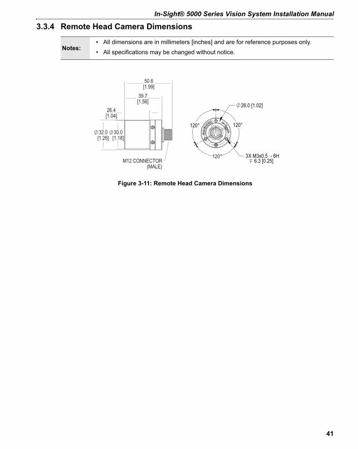
Figure 3-11: Remote Head Camera Dimensions
3.3.4 Remote Head Camera Dimensions
6.3 [0.25]3X M3x0.5 - 6H
50.6[1.99]
39.7[1.56]
26.4[1.04]
30.0[1.18]
32.0[1.26]
M12 CONNECTOR(MALE)
26.0 [1.02]
120°
120°
120°
Notes:• All dimensions are in millimeters [inches] and are for reference purposes only.
• All specifications may be changed without notice.
41
Specifications
Figure 3-12: Remote Head Camera Enclosure Dimensions
3.3.5 Remote Head Camera Enclosure Dimensions
46.0[1.81]
3 MOUNTING HOLESM3 SCREWS6.3 [.25] DEEP
10.9[0.43]
93.6[3.69]
NOMINAL79.2[3.12]
66.6[2.62]44.1
[1.74]NOMINAL29.6
[1.17]
REMOTE HEAD(NOT SECTIONED)
LENS
ENCLOSURE GLASS
35.0[1.38]42.0
[1.65]
Notes:• All dimensions are in millimeters [inches] and are for reference purposes only.
• All specifications may be changed without notice.
42

In-Sight® 5000 Series Vision System Installation Manual
Figure 3-13: Remote Head Camera Mount Dimensions
3.3.6 Remote Head Camera Mount Dimensions
The remote head mounting bracket dimensions are illustrated below. Refer to Appendix A for installation instructions.
50.8[2.00]
34.5[1.36]
27.4[1.08]
23.3[.92]
27.4[1.08]
M3 THRU3 HOLES
40.6[1.60]
4.8[.19]
17.3[.68]10.0
[.39]
21.3 [.84]16.2 [.64]
8.1 [.32]
10.0[.39]
Ø.25 THRU
¼-20 THREADEDTHRU
M6 THRU2 HOLES
41.2[1.62]
19 [.75]
17.3[.68]
MOUNTING BRACKET
35.0[1.38]
MOUNTING BRACKET WITH REMOTE HEAD AND VIBRATION DAMPENER
31.5[1.24]
Notes:• All dimensions are in millimeters [inches] and are for reference purposes only.
• All specifications may be changed without notice.
43

Specifications
Figure 3-14: 5600 and 5603 Vision System Dimensions (With Lens Cover)
3.3.7 5600 and 5603 Vision System Dimensions
OPTICAL
1.50
25.0 .98
25.4 1.00
OPTICALAXIS
OPTICALAXIS
4.30109.1
52.0 2.05
99.9 3.93
36.9 1.45
OPTICALAXIS
3.8698.0
5.719.5 .77
1.97
.23
50.0
.225.6
22.4 .88
4X M4 8.0
OPTICALAXIS
AXIS
OPTICALAXIS
30.0 1.18
4X M4 4.0
31.0 1.22
61.4 2.42
4.88124.1
1.3033.0
36.0 1.42
38.1
Notes:• All dimensions are in millimeters [inches] and are for reference purposes only.
• All specifications may be changed without notice.
44

In-Sight® 5000 Series Vision System Installation Manual
Figure 3-15: 5600 and 5603 Vision System Dimensions (Without Lens Cover)
25.0 .98
25.4 1.00
OPTICALAXIS
OPTICALAXIS
3.8698.0
5.719.5 .77
1.97
.23
50.0
.225.6
22.4 .88
4X M4 8.0
OPTICALAXIS
1.2231.0
2.4261.4
124.1 4.88
33.0 1.30
4X M4 4.0
30.0 1.18
OPTICALAXIS
59.4 2.34
OPTICALAXIS
1.50
OPTICALAXIS
4.30109.1
52.0 2.05
36.9 1.4538.1
36.0 1.42
45
Specifications
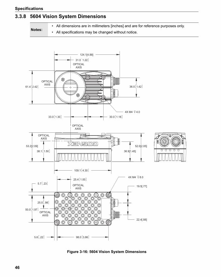
Figure 3-16: 5604 Vision System Dimensions
3.3.8 5604 Vision System Dimensions
25.4 1.00
38.1 1.50
OPTICALAXIS
OPTICALAXIS
AXISOPTICAL
OPTICALAXIS
3.8698.0
50.0
19.5[.77]
1.97
.23
22.4[.88]
5.6 .22
5.7
25.0 .98
4X M4 8.0
36.0
124.1[4.88]
30.0 1.18
1.422.4261.4
33.0 1.30
31.0 1.22
4X M4 4.0
OPTICALAXIS
OPTICALAXIS
53.2[2.09]
36.9[1.45]
109.1 4.30
52.0[2.05]
Notes:• All dimensions are in millimeters [inches] and are for reference purposes only.
• All specifications may be changed without notice.
46
Appendix A
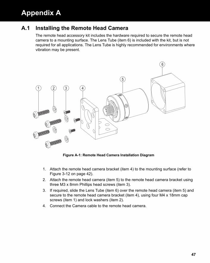
Figure A-1: Remote Head Camera Installation Diagram
A.1 Installing the Remote Head CameraThe remote head accessory kit includes the hardware required to secure the remote head camera to a mounting surface. The Lens Tube (item 6) is included with the kit, but is not required for all applications. The Lens Tube is highly recommended for environments where vibration may be present.
1 2 3 4
5
6
1. Attach the remote head camera bracket (item 4) to the mounting surface (refer to Figure 3-12 on page 42).
2. Attach the remote head camera (item 5) to the remote head camera bracket using three M3 x 8mm Phillips head screws (item 3).
3. If required, slide the Lens Tube (item 6) over the remote head camera (item 5) and secure to the remote head camera bracket (item 4), using four M4 x 18mm cap screws (item 1) and lock washers (item 2).
4. Connect the Camera cable to the remote head camera.
47

Appendix A - Installing the Remote Head Camera
48
Appendix B
B.1 Cleaning/Maintenance
B.1.1 Cleaning the Vision SystemTo clean the outside of the vision system, use a small amount of mild detergent cleaner or isopropyl alcohol on a cleaning cloth. Do not pour the cleaner directly onto the vision system.
B.1.2 Cleaning the CCD WindowTo remove dust from the outside of the CCD window, use a pressurized air duster. The air must be free of oil, moisture or other contaminants that could remain on the glass and possibly degrade the image. Do not touch the glass window. If oil/smudges still remain, clean the window with a cotton bud using alcohol (ethyl, methyl or isopropyl). Do not pour the alcohol directly on the window.
Note:Do not attempt to clean In-Sight products with harsh or corrosive solvents, including Lye, methyl ethyl ketone (MEK) or gasoline.
49

Appendix B - Cleaning/Maintenance
50


P/N 597-0027-06Printed in the USA